LITTLE DAVID - Loveshaw · 2016-04-23 · little david tape cartridge manual .cac60 /.cac61 the...
26
LITTLE DAVID TAPE CARTRIDGE MANUAL .CAC60 /.CAC61 THE LOVESHAW CORPORATION LOVESHAW - EUROPE 2206 EASTON TURNPIKE, BOX 83 UNIT 9, BRUNEL GATE SOUTH CANAAN, PA 18459 W. PORTWAY INDUSTRIAL ESTATE ANDOVER, HAMPSHIRE SP103SL TEL: (570) 937-4921 ENGLAND FAX: (570) 937-4370 44-264-3575-11
Transcript of LITTLE DAVID - Loveshaw · 2016-04-23 · little david tape cartridge manual .cac60 /.cac61 the...

LITTLE DAVID TAPE CARTRIDGE MANUAL
.CAC60 /.CAC61
THE LOVESHAW CORPORATION LOVESHAW - EUROPE 2206 EASTON TURNPIKE, BOX 83 UNIT 9, BRUNEL GATE SOUTH CANAAN, PA 18459 W. PORTWAY INDUSTRIAL ESTATE ANDOVER, HAMPSHIRE SP103SL TEL: (570) 937-4921 ENGLAND FAX: (570) 937-4370 44-264-3575-11

1
Part and Instruction Manual
Loveshaw Pressure Sensitive Tape Cartridge
CAC60 – 2” wide tape
CAC61 – 3” wide tape
This is a combined manual for the CAC60 – 2” wide tape and the CAC61 – 3” wide tape. Take care when ordering parts. Make sure it is for the correct width cartridge.
For stainless steel cartridge parts add the suffix “SS” to the part numbers depicted in the assembly drawings.

2
Theory of Operation:
Pressure sensitive tape is applied to the corrugated box as it passes by the cartridge. The box will contact the front arm roller which has pressure sensitive tape adhesive side facing outward towards the oncoming box. The front leading side of the box will contact the front roller arm and the tape will adhere to the box. As the box continues to move forward the front roller arm and knife arm will be rotated into the frame of the cartridge. The amount of force exerted on the box as tape is being applied is adjustable by changing the position of the main spring. The front arm initial application force can be set to accommodate the strength of the box as well as the sturdiness of the contents in the box.
As the front arm application roller transitions from the leading panel of the box to the top major flaps a separate wipe down spring is engaged. The sole purpose of this spring is to add speed to the rear wipe roller actuation to insure the rear tape tab is completely wiped to the rear trailing panel of the box. At this time the knife arm is retracted into the cartridge and the knife blade guard is fully retracted uncovering the blade. As the knife arm rotated into the cartridge the knife activation spring extends, generating cut force.
As the box proceeds pass the cartridge the front arm roller will no longer contact the major flaps of the box, but the rear wipe roller will still contact the major flaps. Eventually as the box travels the knife arm will completely stop contacting the major flaps of the box. This will allow the knife arm to travel back towards its home position allowing the knife blade to puncture and cut through the tape. As the box continues move the rear wipe arm roller will no longer contact the major flaps of the box. This will allow the wipe arm roller to spring out of the cartridge and contact the rear tab length of tape and press against the trailing panel of the box. The rear wipe arm roller booster spring starts the wipe and the main cartridge spring finishes the wipe sequence.
The box travelling pass the cartridge is the vehicle which pulls the tape through the cartridge. The cartridge is design to run most pressure sensitive tapes with no required adjustments. However in some cases it may be necessary to adjust tape tensions. The cartridge will operate at speeds up to 150 feet/minute.

3
Important Safety Notices:
Before installing operating or servicing the tape cartridges read carefully and understand the following precautions:
• Never service the tape cartridges when installed in an operating machine.
• Use lock out / tag out protocols before installing or removing cartridges from machinery.
• Do not bypass or remove safety guard on knife blade.
• Observe caution when near tape cartridge knife. The knife
blade is protected by a locking cover which is held closed by the link bar.
• Never make any adjustments to the tape cartridges when
installed in an operating machine.

4
Tape Threading:
The first step is to place the tape roll, on the cartridge exspandable tape core. Rotate the tape tension arm clockwise until it locks in place in its fully open position. (refer to figure 3) The tape core diameter is adjustable by turning the adjustor nut. Turning the adjustor nut c.w. the core diameter increases and turning it c.c.w. the tape core diameter decreases. Decrease the tape core enough in order to place the tape roll on the core. Now turn the adjustor nut clockwise until the tape roll is snuggly held. (refer to figure1)
Tape roll must be placed on tape core with adhesive side of tape facing to the right. Refer to figure 2and 3 for proper orientation.
Continue threading the tape over the upper and lower white tension arm rollers. Threading arrows are installed throughout the tape path of the cartridge to aid in threading. The back of the tape, the non adhesive side rides against the front of the rollers. It is important to insure that the tape tension arm is not bent; since this will cause the tape not to track properly through the cartridge. Refer to figure 3.
Adjustor nut
Figure 1 Figure 2
Adhesive side

5
The tape is then threaded around the knurled tape tension roller. The adhesive side of the tape contacts the knurled roller. Refer to figure 4.
Figure 3
Tension arm upper roller
Tension arm
Tension arm lower roller
Arm lock release
Knurled tension roller
Figure 4
6
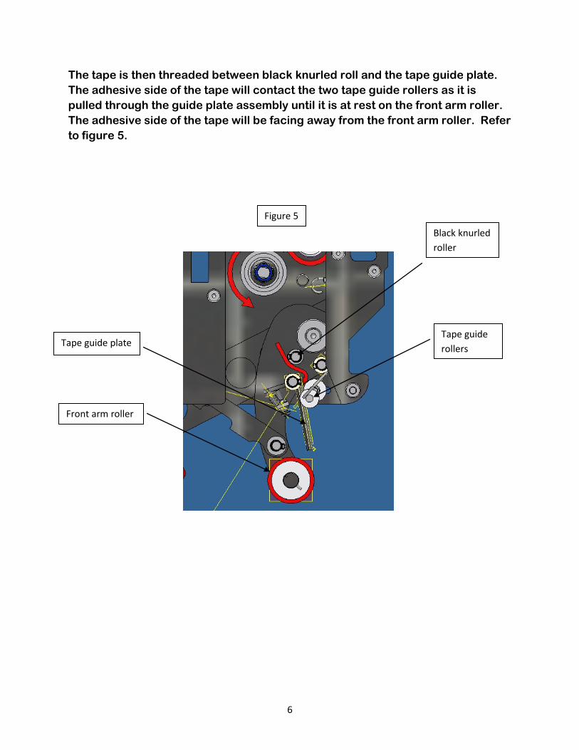
The tape is then threaded between black knurled roll and the tape guide plate. The adhesive side of the tape will contact the two tape guide rollers as it is pulled through the guide plate assembly until it is at rest on the front arm roller. The adhesive side of the tape will be facing away from the front arm roller. Refer to figure 5.
Figure 5
Black knurled roller
Front arm roller
Tape guide plate Tape guide rollers

7
Adjustments:
• Aligning tape : Aligning tape side to side with in the cartridge frame is done by changing the position of the tape core. This is done by first loosening the tape core locking screw with a 3mm hex key. Turn the tape core locking screw counter clockwise allowing for the desired amount of adjustment to be made. Now turn the tape core height adjusting nut until the desired result is obtained. By turning the tape core height adjusting nut clockwise the tape core height position will decrease moving the tape closer to the mill stand side of the cartridge. By turning the tape core height adjusting nut counter clockwise the tape core height position will increase. This will make the tape track further away from the mill stand. After each adjustment always tighten the tape core locking screw. Failure to do so will allow the tape core position to change as tape is being pulled of f the tape roll. Refer to figure 6
Figure 6
Tape core height locking screw
Tape core height adjusting nut
Tape core friction drag adjustor ring

8
• Setting tape core drag: The tape core drag setting is factory set to not allow a full roll of tape to free wheel as tape is being pulled off it. The tape tension arm assembly automatically adjusts for the proper amount of tape tension to be applied as the tape roll diminishes in diameter as tape is applied. The drag setting may need to be adjusted if the tape cartridge is being operated at high speed or if the tape adhesive is causing the roll to over rotate as the tape it is being pulled of the roll. Refer to figure 6.
• Setting the knurled tension roller:
The knurled tension roller is factory set to its minimum resistance setting. This setting works for all standard tape applications. The tension roller setting may need to be adjusted if a thick mill tape is being used. By increasing the tension it aids in cutting the tape. Refer to figure7.
• Setting main spring tension:
Setting the main spring tension is done by moving the end of the spring to a different preset position. The main spring tension is factory set to a mid position. The spring is set from lightest to stoutest dependant on the strength of the corrugated box and the fill of the contents. Void filled,
Figure 7
Tension roller adjustor nut

9
weak corrugated boxes would be set to the lightest setting while strong corrugated box with overfill would process better with the main spring set stronger. The main spring only effects the application and wipe rollers. Refer to figure 8.
• Setting booster spring compression
The booster spring aids in rear tab wipe. The booster spring preloads the wipe roller arm so when the trailing edge of the box releases the wipe roller the arm can travel out a higher rate of speed and contact the rear tab and secure it to the back panel of the box. The booster adjuster is
Figure 8
Main spring tension adjustment
Strongest setting
Weakest setting
Main spring Booster spring
Booster adjustment

10
factory set to lightly engage when the front roller arm is completely retracted. The booster setting is adjusted stronger when the cartridge is operated at higher application speeds. Refer to figure 8.
• Setting the rear tab cut adjustor:
The rear tab cut adjustor is factory set to operate at 60 to 80ft/min belt speed. If the cartridge is operating at higher speeds the adjustor would need to move in order to shorten the rear tab length. The adjustor only alters the rear tab length. The front tab length is fixed and cannot be adjusted. Refer to figure 9.
• Front arm stopper adjustment:
The front arm stop adjustment is factory set to insure that the front arm roller stays in contact with major flaps of the box. This allows for a tight tape seal across the horizontal length of the box. The adjustor does not
Figure 9
Tab adjustor
Increase
Decrease

11
need to be adjusted for normal applications. In some cases it may be necessary to adjust the stop depending on the type of machine that the cartridge is being used in. If the cartridge is placed in a machine and the tape is not being applied to the major flaps with enough pressure an adjustment will be necessary. This will be evident by inspecting the box as it exits the machine. Normal symptoms include the tape bridging across the major flaps, or the tape bunching up on the major flaps after the tape was cut. Refer to figure 10.
Figure 10
Jam nut
Front arm stopper

12
Maintenance:
• Application / Wipe roller replacement:
Roller replacement is a tool less procedure. Simply push down on retaining pin and slide roller off the shaft. Install new roller in opposite fashion. Take caution to install replacement roller with undercut facing toward arm away from retaining pin. Refer to figure 11.
• Knife blade replacement:
Knife blade replacement is a tool less procedure. Simply push down on release bar and pull knife blade out. Fold back the knife guard by first
Figure 11
Retaining pin
13
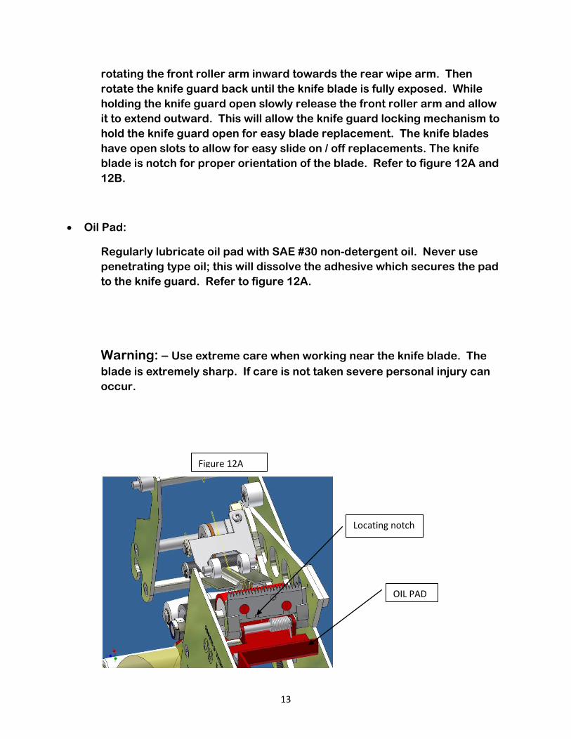
rotating the front roller arm inward towards the rear wipe arm. Then rotate the knife guard back until the knife blade is fully exposed. While holding the knife guard open slowly release the front roller arm and allow it to extend outward. This will allow the knife guard locking mechanism to hold the knife guard open for easy blade replacement. The knife blades have open slots to allow for easy slide on / off replacements. The knife blade is notch for proper orientation of the blade. Refer to figure 12A and 12B.
• Oil Pad:
Regularly lubricate oil pad with SAE #30 non-detergent oil. Never use penetrating type oil; this will dissolve the adhesive which secures the pad to the knife guard. Refer to figure 12A.
Warning: – Use extreme care when working near the knife blade. The blade is extremely sharp. If care is not taken severe personal injury can occur.
Figure 12A
Locating notch
OIL PAD

14
Knife guard is shown open in both figures.
Figure 12B
Blade release bar
15
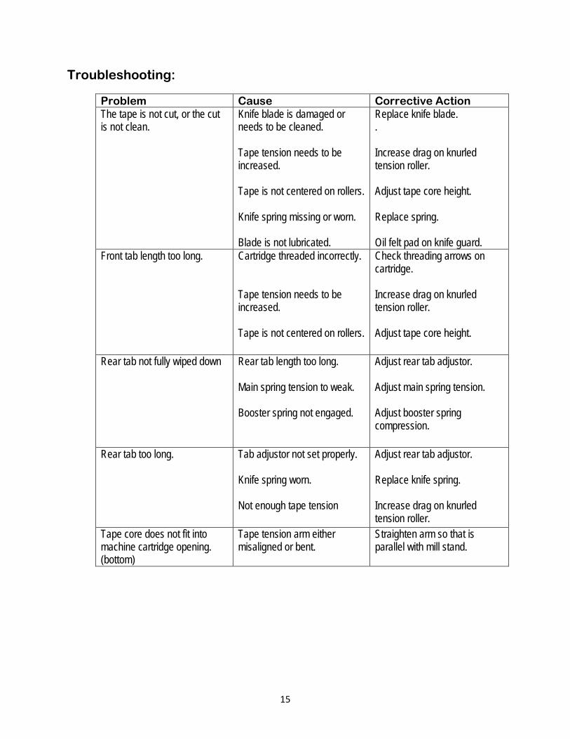
Troubleshooting:
Problem Cause Corrective Action The tape is not cut, or the cut is not clean.
Knife blade is damaged or needs to be cleaned. Tape tension needs to be increased. Tape is not centered on rollers. Knife spring missing or worn. Blade is not lubricated.
Replace knife blade. . Increase drag on knurled tension roller. Adjust tape core height. Replace spring. Oil felt pad on knife guard.
Front tab length too long. Cartridge threaded incorrectly. Tape tension needs to be increased. Tape is not centered on rollers.
Check threading arrows on cartridge. Increase drag on knurled tension roller. Adjust tape core height.
Rear tab not fully wiped down Rear tab length too long. Main spring tension to weak. Booster spring not engaged.
Adjust rear tab adjustor. Adjust main spring tension. Adjust booster spring compression.
Rear tab too long. Tab adjustor not set properly. Knife spring worn. Not enough tape tension
Adjust rear tab adjustor. Replace knife spring.
Increase drag on knurled tension roller.
Tape core does not fit into machine cartridge opening. (bottom)
Tape tension arm either misaligned or bent.
Straighten arm so that is parallel with mill stand.

1
1
2
2
3
3
4
4
A A
B B
C C
D D
TITLE
DWG NO SCALE
DRAWN
CHECKED
APPROVED
LOVESHAW an CompanyRT. 296, SOUTH CANAAN, PA.
ITW
MATERIAL
TOLERANCES UNLESS OTHERWISE NOTED:
INCH
METRIC
.X
.XX
.XXX
= .050= .015
= .005+
-++
---
.X
.XX
.XXX
= 1.0mm= .3mm
= .1mm
++
+
--
-
FRACTIONS 1/64+-
ANGLES 1/2~+-
-
MACH.FINISH
125
CAD FILE
PLOT DATE
DRAWN DATE
DO NOT SCALE PRINT
MAT'L
C.R.S.
ST. ST.
STD
PART #
STAINLESS : NO FINISH
THIS DRAWING AND SUBJECT MATTER THEREON IS THE EXCLUSIVE PROPERTY OF LOVESHAW-ITW AND IS TO BE TREATED BY YOU AS CONFIDENTIAL PRPRIETARYINFORMATION. THIS DRAWING OR SUBJECT MATTER THEROF SHALL NOT BEREPRODUCED OTHER THAN FOR YOUR OWN USE OR TO BE DISCLOSED TO OTHERWITHOUT THE EXPRESSED WRITTEN CONSENT OF LOVESHAW-ITW AND WILL BERETURNED TO LOVESHAW-ITW UPON REQUEST.
.CAC60 / .CAC61 SERIES OVERVIEW
OVERVIEW-CAC60-61
AMYR
11/14/2008
11/14/2008
.CAC60 / .CAC61 SERIES
Parts ListDESCRIPTIONPART NUMBERQTYITEM
FRONT ROLLER ARM ASSEMBLY.FRACAC6011REAR ROLLER ARM ASSEMBLY.RRACAC6012KNIFE ASSEMBLY.KAACAC6013TAPE CORE ASSEMBLY 2".TCA214TENSION ARM ASSEMBLY.TAACAC6015MILLSTAND DECALSL-0030162" BASE ASSEMBLY.CAC60 SERIES17TENSION ROLLER ASSEMBLY.TRA6018
Parts ListDESCRIPTIONPART NUMBERQTYITEM
FRONT ROLLER ARM ASSEMBLY.FRACAC6111REAR ROLLER ARM ASSEMBLY.RRACAC6112KNIFE ASSEMBLY.KAACAC6113TAPE CORE ASSEMBLY 3".TCA314TENSION ARM ASSEMBLY.TAACAC6115MILLSTAND DECALSL-0030163" BASE ASSEMBLY.CAC61 SERIES17TENSION ROLLER ASSEMBLY.TRA6118
REVISION HISTORYREV DESCRIPTION DATE BY
A RELEASED 11/14/2008 AMYR
1
2
3
4
8
5
6
7 PARTS FOR .CAC60 2" CARTRIDGE
PARTS FOR .CAC61 3" CARTRIDGE

1
1
2
2
3
3
4
4
A A
B B
C C
D D
TITLE
DWG NO SCALE
DRAWN
CHECKED
APPROVED
LOVESHAW an CompanyRT. 296, SOUTH CANAAN, PA.
ITW
MATERIAL
TOLERANCES UNLESS OTHERWISE NOTED:
INCH
METRIC
.X
.XX
.XXX
= .050= .015
= .005+
-++
---
.X
.XX
.XXX
= 1.0mm= .3mm
= .1mm
++
+
--
-
FRACTIONS 1/64+-
ANGLES 1/2+-
-
MACH.FINISH
125
CAD FILE
PLOT DATE
DRAWN DATE
DO NOT SCALE PRINT
MAT'L
C.R.S.
ST. ST.
STD
PART #
STAINLESS : NO FINISH
THIS DRAWING AND SUBJECT MATTER THEREON IS THE EXCLUSIVE PROPERTY OF LOVESHAW-ITW AND IS TO BE TREATED BY YOU AS CONFIDENTIAL PRPRIETARYINFORMATION. THIS DRAWING OR SUBJECT MATTER THEROF SHALL NOT BEREPRODUCED OTHER THAN FOR YOUR OWN USE OR TO BE DISCLOSED TO OTHERWITHOUT THE EXPRESSED WRITTEN CONSENT OF LOVESHAW-ITW AND WILL BERETURNED TO LOVESHAW-ITW UPON REQUEST.
BASE ASSEMBLY 2" / 3"
BASE ASSEMBLY
AMYR
6/26/2008
4/6/2009
.CAC60 / .CAC61 SERIES
CARTRIDGE PARTS LIST DESCRIPTIONPART NUMBERQTYITEM
MAIN FRAMECAC60-0000-611PIVOT SHAFTCAC60-0016-322SHAFT CAPCAC60-0017-323SPRING STUDCAC60-0033-314STOPPER FRONT ARMCAC50-050-325SIDE FRAME MEDIUMCAC60-0039-616TIE SHAFTCAC60-0040-377SIDE FRAME SMALLCAC60-0041-518MILLSTANDCAC60-0031-419SHAFT MILLSTANDCAC60-0058-3110SPRING SHAFTCAC60-0060-3111SPACERCAC50-0059-3112RUBBER BUMPERSPH-1371113STOP MOUNTCAC60-0071-3114FL. HD. CAP SCREW M5 X 0.8 X 12 LG.FFHMF012P102415FL. HD. CAP SCREW M6 X 1.0 X 16 LG.FFHMG016P10416HEX JAM NUT M5 FHJNMFP317FL. HD. CAP SCREW M5 X 16 LG.FFHMF016P10118LOCK WASHER M5FLWMFP219HEX NUT M5 FHFNMFP220FL. HD. CAP SCREW M5 X 0.8 X 8 LG.FFHMF008P10221MAIN SPRING CARTRIDGESPR-1062122
CARTRIDGE PARTS LIST DESCRIPTIONPART NUMBERQTYITEM
MAIN FRAMECAC60-0000-611PIVOT SHAFTCAC60-0016-322SHAFT CAPCAC60-0017-323SPRING STUDCAC60-0033-314STOP FRONT ARMCAC50-050-325SIDE FRAME MEDIUMCAC60-0039-616TIE SHAFTCAC60-0040/3-377SIDE FRAME SMALLCAC60-0041-518MILLSTANDCAC60-0031-419SHAFT MILLSTANDCAC60-0058/3-3110SPRING SHAFTCAC60-0060/3-3111SPACERCAC60-0059-3112RUBBER BUMPERSPH-1371113STOP MOUNTCAC60-0071-3114FL. HD. CAP SCREW M5 X 0.8 X 12 LG.FFHMF012P102415FL. HD. CAP SCREW M6 X 1.0 X 16 LG.FFHMG016P10416HEX JAM NUT M5 FHJNMFP317FL. HD. CAP SCREW M5 X 16 LG.FFHMF016P10118LOCK WASHER M5FLWMFP219HEX NUT M5FHFNMFP220FL. HD. CAP SCREW M5 X 0.8 X 8 LG.FFHMF008P10221MAIN SPRING CARTRIDGEPSC501101-4122
REVISION HISTORYREV DESCRIPTION DATE BY
A RELEASED 6/26/2008 AMYRB M.C.R. #08-010 11/20/2008 AMYRC M.C.R. #09-003 2/17/2009 AMYR
PARTS FOR .CAC60 2" CARTRIDGE
PARTS FOR .CAC61 3" CARTRIDGE
15
7
610
3
2
2019
11
7
8
16
3
7
17
5
12
2
17
18
16
13
14
9
17
122
24
21
4
15

1
1
2
2
3
3
4
4
A A
B B
C C
D D
TITLE
DWG NO SCALE
DRAWN
CHECKED
APPROVED
LOVESHAW an CompanyRT. 296, SOUTH CANAAN, PA.
ITW
MATERIAL
TOLERANCES UNLESS OTHERWISE NOTED:
INCH
METRIC
.X
.XX
.XXX
= .050= .015
= .005+
-++
---
.X
.XX
.XXX
= 1.0mm= .3mm
= .1mm
++
+
--
-
FRACTIONS 1/64+-
ANGLES 1/2+-
-
MACH.FINISH
125
CAD FILE
PLOT DATE
DRAWN DATE
DO NOT SCALE PRINT
MAT'L
C.R.S.
ST. ST.
STD
PART #
STAINLESS : NO FINISH
THIS DRAWING AND SUBJECT MATTER THEREON IS THE EXCLUSIVE PROPERTY OF LOVESHAW-ITW AND IS TO BE TREATED BY YOU AS CONFIDENTIAL PRPRIETARYINFORMATION. THIS DRAWING OR SUBJECT MATTER THEROF SHALL NOT BEREPRODUCED OTHER THAN FOR YOUR OWN USE OR TO BE DISCLOSED TO OTHERWITHOUT THE EXPRESSED WRITTEN CONSENT OF LOVESHAW-ITW AND WILL BERETURNED TO LOVESHAW-ITW UPON REQUEST.
FRONT ROLLER ARM ASSEMBLY
FRACAC60
AMYR
6/24/2008
2/17/2009
.FRACAC60/61
Parts ListDESCRIPTIONPART NUMBERQTYITEM
FRONT ROLLER ARMCAC60-0001-611WAVE WASHERSPH-125212TAPE GUIDE PLATECAC60-0004-413LINK BARCAC60-0007-514BUSHING, OILITECAC60-0047-335BRONZE WASHER 5/16"SPH-127716SNAP RING, 8mmSPH-127657FLANGE BUSHING 8mmBSG-109048SPRING, COMPRESSIONSPR-104419SLIDING BLOCKCAC60-0008-4110BUSHINGCAC60-0009-3111EXTERNAL RETAINING RING, 16mmSPH-1334112ROLLER SHAFT, QUICK RELEASECAC60-0048-4113DOWEL PIN STAINLESSSPH-1335114SPRING PINSPH-1336115ROLLERCAC60-0002-4116SPRINGSPR-1046117WASHER M8SPH-1339218KNIFE GUARD LOCKCAC60-0068-4119BUSHINGBSG-1098220SMALL ROLLERCAC60-0073-3121BUTT. HD. M4 X 12 LG.FBHME012P10522FL. HD. CAP SCREW M6 X 1.0 X 16 LG.FFHMG016P10123BUSHING 16mmBSG-1085124PAN HEAD SCREW M4 X 20 LG.FBHME020P10125HEX NUT M4FHFNMEP126EXTENSION SPRINGSPR-1055127FINGER PLATE ASSEMBLY.FPACAC60128FLAT WASHER M5FFWMFP129M3 x 0.5 Hex NutFHJNMDP230
Parts ListDESCRIPTIONPART NUMBERQTYITEM
FRONT ROLLER ARMCAC60-0001/3-611WAVE WASHERSPH-125212TAPE GUIDE PLATECAC60-0004/3-413LINK BARCAC60-0007-514BUSHING, OILITECAC60-0047-335BRONZE WASHER 5/16"SPH-127716SNAP RING, 8mmSPH-127657FLANGE BUSHING 8mmBSG-109048SPRING, COMPRESSIONSPR-104419SLIDING BLOCKCAC60-0008-4110BUSHINGCAC60-0009-3111EXTERNAL RETAINING RING, 16mmSPH-1334112ROLLER SHAFT, QUICK RELEASECAC60-0048/3-4113DOWEL PIN STAINLESSSPH-1335114SPRING PINSPH-1336115ROLLERCAC60-0002/3-4116SPRINGSPR-1046117WASHER M8SPH-1339218KNIFE GUARD LOCKCAC60-0068-4119BUSHINGBSG-1098220SMALL ROLLERCAC60-0073/3-3121BUTT. HD. M4 X 12 LG.FBHME012P10422FL. HD. CAP SCREW M6 X 1.0 X 16 LG.FFHMG016P10123BUSHING 16mmBSG-1085124PAN HEAD SCREW M4 X 20 LG.FBHME020P10125HEX NUT M4FHFNMEP126EXTENSION SPRINGSPR-1055127FINGER PLATE ASSEMBLY.FPACAC61128FLAT WASHER M5FFWMFP129M3 x 0.5 Hex NutFHJNMDP130
REVISION HISTORYREV DESCRIPTION DATE BY
A RELEASED 6/24/2008 AMYRB M.C.R. #09-003 2/17/2009 AMYR
1
20
8
3
16
2
10
21
7
13
15
14
17
18 5
4
22
19
6
115
7
8
20
18
5
8
7
8
12
7
23
27 25
26
24
PARTS FOR .CAC60 2" CARTRIDGE
PARTS FOR .CAC61 3" CARTRIDGE
28
9
29
22

1
1
2
2
3
3
4
4
A A
B B
C C
D D
TITLE
DWG NO SCALE
DRAWN
CHECKED
APPROVED
LOVESHAW an CompanyRT. 296, SOUTH CANAAN, PA.
ITW
MATERIAL
TOLERANCES UNLESS OTHERWISE NOTED:
INCH
METRIC
.X
.XX
.XXX
= .050= .015
= .005+
-++
---
.X
.XX
.XXX
= 1.0mm= .3mm
= .1mm
++
+
--
-
FRACTIONS 1/64+-
ANGLES 1/2~+-
-
MACH.FINISH
125
CAD FILE
PLOT DATE
DRAWN DATE
DO NOT SCALE PRINT
MAT'L
ST. ST.
STD
PART #
STAINLESS : NO FINISH
THIS DRAWING AND SUBJECT MATTER THEREON IS THE EXCLUSIVE PROPERTY OF LOVESHAW-ITW AND IS TO BE TREATED BY YOU AS CONFIDENTIAL PRPRIETARYINFORMATION. THIS DRAWING OR SUBJECT MATTER THEROF SHALL NOT BEREPRODUCED OTHER THAN FOR YOUR OWN USE OR TO BE DISCLOSED TO OTHERWITHOUT THE EXPRESSED WRITTEN CONSENT OF LOVESHAW-ITW AND WILL BERETURNED TO LOVESHAW-ITW UPON REQUEST. AMYR
6/25/2008
11/7/2008
.RRACAC60/61
REAR ROLLER ARM ASSEMBLY
RRACAC60.idw
Parts ListDESCRIPTIONPART NUMBERQTYITEM
REAR ROLLER ARMCAC60-0006-511ROLLERCAC60-0002-412WAVE WASHERSPH-125213BUSHING 16mmBSG-108524STANDOFFCAC60-0018-315ROD END, M6SPH-126716SLIDING RODCAC60-0010-417COMPRESSION SPRINGSPR-103618RETAINING RING 8mmSPH-127619SPACERCAC60-0034-3110ROLLER SHAFT, QUICK RELEASECAC60-0048-4111DOWEL PIN STAINLESSSPH-1335112SPRING PINSPH-1336113SPRINGSPR-1046114SHAFT COLLARSPH-1338115FL. HD. CAP SCREW M6 X 1.0 X 16 LG.FFHMG016P10216BUTT. HD. CAP SCREW M6 X 16 LG.FBHMF016P10117HEX NUT M6FHFNMGP118
Parts ListDESCRIPTIONPART NUMBERQTYITEM
REAR ROLLER ARMCAC60-0006-511ROLLERCAC60-0002/3-412WAVE WASHERSPH-125213BUSHING 16mmBSG-108524STANDOFFCAC60-0018-315ROD END , M6SPH-126716SLIDING RODCAC60-0010-417COMPRRESSION SPRINGSPR-103618RETAINING RING 8mmSPH-127619SPACERCAC60-0034-3110ROLLER SHAFT, QUICK RELEASECAC60-0048/3-4111DOWEL PIN STAINLESSSPH-1335112SPRING PINSPH-1336113SPRINGSPR-1046114SHAFT COLLARSPH-1338115FL. HD. CAP SCREW M6 X 1.0 X 16 LG.FFHMG016P10216BUTT. HD. CAP SCREW M6 X 16 LG.FBHMF016P10117HEX NUT M6FHFNMGP118
REVISION HISTORYREV DESCRIPTION DATE BY
A RELEASED 6/25/2008 AMYR
18
16
1
14
13
11
4
12
9
8
7
5
2
10
3
4
15
6
17
16
PARTS FOR .CAC60 2" CARTRIDGE
PARTS FOR .CAC61 3" CARTRIDGE

1
1
2
2
3
3
4
4
A A
B B
C C
D D
TITLE
DWG NO SCALE
DRAWN
CHECKED
APPROVED
LOVESHAW an CompanyRT. 296, SOUTH CANAAN, PA.
ITW
MATERIAL
TOLERANCES UNLESS OTHERWISE NOTED:
INCH
METRIC
.X
.XX
.XXX
= .050= .015
= .005+
-++
---
.X
.XX
.XXX
= 1.0mm= .3mm
= .1mm
++
+
--
-
FRACTIONS 1/64+-
ANGLES 1/2~+-
-
MACH.FINISH
125
CAD FILE
PLOT DATE
DRAWN DATE
DO NOT SCALE PRINT
MAT'L
C.R.S.
ST. ST.
STD
PART #
STAINLESS : NO FINISH
THIS DRAWING AND SUBJECT MATTER THEREON IS THE EXCLUSIVE PROPERTY OF LOVESHAW-ITW AND IS TO BE TREATED BY YOU AS CONFIDENTIAL PRPRIETARYINFORMATION. THIS DRAWING OR SUBJECT MATTER THEROF SHALL NOT BEREPRODUCED OTHER THAN FOR YOUR OWN USE OR TO BE DISCLOSED TO OTHERWITHOUT THE EXPRESSED WRITTEN CONSENT OF LOVESHAW-ITW AND WILL BERETURNED TO LOVESHAW-ITW UPON REQUEST.
TENSION ROLLER ASSEMBLY CAC60/61
TRA60-61
AMYR
1/19/2009
1/19/2009
.TRA60/61
Parts ListDESCRIPTIONPART NUMBERQTYITEM
SHAFT, KNURLED ROLLERCAC60-0074-411LOCKING WASHERCAC60-0077-312WASHER, SPRINGPSC321039A43BEARINGBRG-109814BEARINGBRG-109915BRAKE WASHERCAC60-0076-326NYLOCK NUT M10FNLNMIP17KNURLED ROLLERCAC60-0075-418
Parts ListDESCRIPTIONPART NUMBERQTYITEM
SHAFT, KNURLED ROLLERCAC60-0074/3-411LOCKING WASHERCAC60-0077-312WASHER, SPRINGPSC321039A43BEARINGBRG-109814BEARINGBRG-109915BRAKE WASHERCAC60-0076-326NYLOCK NUT M10FNLNMIP17KNURLED ROLLERCAC60-0075/3-418
REVISION HISTORYREV DESCRIPTION DATE BY
A RELEASED 1/19/2009 AMYR
4
8
65
1
7
6
2
3
3
3
3
PARTS FOR .CAC60 2" CARTRIDGE
PARTS FOR .CAC61 3" CARTRIDGE

1
1
2
2
3
3
4
4
A A
B B
C C
D D
TITLE
DWG NO SCALE
DRAWN
CHECKED
APPROVED
LOVESHAW an CompanyRT. 296, SOUTH CANAAN, PA.
ITW
MATERIAL
TOLERANCES UNLESS OTHERWISE NOTED:
INCH
METRIC
.X
.XX
.XXX
= .050= .015
= .005+
-++
---
.X
.XX
.XXX
= 1.0mm= .3mm
= .1mm
++
+
--
-
FRACTIONS 1/64+-
ANGLES 1/2~+-
-
MACH.FINISH
125
CAD FILE
PLOT DATE
DRAWN DATE
DO NOT SCALE PRINT
MAT'L
C.R.S.
ST. ST.
STD
PART #
STAINLESS : NO FINISH
THIS DRAWING AND SUBJECT MATTER THEREON IS THE EXCLUSIVE PROPERTY OF LOVESHAW-ITW AND IS TO BE TREATED BY YOU AS CONFIDENTIAL PRPRIETARYINFORMATION. THIS DRAWING OR SUBJECT MATTER THEROF SHALL NOT BEREPRODUCED OTHER THAN FOR YOUR OWN USE OR TO BE DISCLOSED TO OTHERWITHOUT THE EXPRESSED WRITTEN CONSENT OF LOVESHAW-ITW AND WILL BERETURNED TO LOVESHAW-ITW UPON REQUEST.
TAPE TENSION ARM ASSEMBLY
.TAACAC60
AMYR
6/26/2008
1/15/2009
.TAACAC60/61
Parts ListDESCRIPTIONPART NUMBERQTYITEM
RETAINING RING 10mmSPH-126821SPRING STUDCAC60-0033-312TAPE TENSION ARM SHAFT STEPPEDCAC60-0056-313TAPE TENSION ARMCAC60-0049-414TAPE TENSION ARM SHAFTCAC60-0054-315CATCH SPRINGSPR-104716BRONZE WASHER, 3/8SPH-134117EXTENSION SPRINGSPR-104818CATCHCAC60-0055-319FL. HD. CAP SCREW M6 X 1.0 X 16 LG.FFHMG016P10110FL. HD. CAP SCREW M5 X 16 LG.FFHMF016P10111CIRCLIP 10mmSPH-1369112TAPERED ROLLERCAC60-0079-4113TAPE TENSION ARM ROLLERCAC60-0052-4114
Parts ListDESCRIPTIONPART NUMBERQTYITEM
RETAINING RING 10mmSPH-126821SPRING STUDCAC60-0033-312TAPE TENSION ARM SHAFT STEPPEDCAC60-0056/3-313TAPE TENSION ARMCAC60-0049-414TAPE TENSION ARM SHAFTCAC60-0054/3-315CATCH SPRINGSPR-104716BRONZE WASHER, 3/8SPH-134117EXTENSION SPRINGSPR-104818CATCHCAC60-0055-319FL. HD. CAP SCREW M6 X 1.0 X 16 LG.FFHMG016P10110FL. HD. CAP SCREW M5 X 16 LG.FFHMF016P10111CIRCLIP 10mmSPH-1369112TAPERED ROLLERCAC60-0079/3-4113TAPE TENSION ARM ROLLERCAC60-0052/3-4114
REVISION HISTORYREV DESCRIPTION DATE BY
A RELEASED 6/26/2008 AMYRB M.C.R. #08-010 11/20/2008 AMYR
2
4
9
8
5
14
3
7
1
1
13
10
11
12 6
PARTS FOR .CAC60 2" CARTRIDGE
PARTS FOR .CAC61 3" CARTRIDGE

1
1
2
2
3
3
4
4
A A
B B
C C
D D
TITLE
DWG NO SCALE
DRAWN
CHECKED
APPROVED
LOVESHAW an CompanyRT. 296, SOUTH CANAAN, PA.
ITW
MATERIAL
TOLERANCES UNLESS OTHERWISE NOTED:
INCH
METRIC
.X
.XX
.XXX
= .050= .015
= .005+
-++
---
.X
.XX
.XXX
= 1.0mm= .3mm
= .1mm
++
+
--
-
FRACTIONS 1/64+-
ANGLES 1/2+-
-
MACH.FINISH
125
CAD FILE
PLOT DATE
DRAWN DATE
DO NOT SCALE PRINT
MAT'L
C.R.S.
ST. ST.
STD
PART #
STAINLESS : NO FINISH
THIS DRAWING AND SUBJECT MATTER THEREON IS THE EXCLUSIVE PROPERTY OF LOVESHAW-ITW AND IS TO BE TREATED BY YOU AS CONFIDENTIAL PRPRIETARYINFORMATION. THIS DRAWING OR SUBJECT MATTER THEROF SHALL NOT BEREPRODUCED OTHER THAN FOR YOUR OWN USE OR TO BE DISCLOSED TO OTHERWITHOUT THE EXPRESSED WRITTEN CONSENT OF LOVESHAW-ITW AND WILL BERETURNED TO LOVESHAW-ITW UPON REQUEST.
KNIFE ASSEMBLY .CAC60/61
KAACAC60
AMYR
6/24/2008
11/10/2009
.KAACAC60/61
Parts ListDESCRIPTIONPART NUMBERQTYITEM
KNIFE ARMCAC60-0022-611KNIFE GUARD PIVOT PINCAC60-0028-312KNIFE GUARDCAC60-0029-513BUSHING, 6mmBSG-109124BUSHINGCAC60-0030-315TAB ADJUSTERCAC60-0036-316PINCAC60-0042-327SPRINGSPR-104548PIN PLATECAC60-0043-319KNIFE BLADE 2"PSC11B60-4110EXTENSION SPRINGSPR-1042111BUTT. HD. M3 X 5 FBHMD005P10212FL. HD. CAP SCREW M4 X 8 FFHME008P10213CUP POINT SET SCREW M4 X 4FSSME004P10214KNIFE GUARD CUSHIONCAC60-0078-3115BRONZE BUSHINGCAC60-0081-3116TORSION SPRINGSPR-1063117
Parts ListDESCRIPTIONPART NUMBERQTYITEM
KNIFE ARMCAC60-0022/3-611KNIFE GUARD PIVOT PINCAC60-0028/3-312KNIFE GUARDCAC60-0029/3-513BUSHING, 6mmBSG-109124BUSHINGCAC60-0030-315TAB ADJUSTERCAC60-0036-316PINCAC60-0042-327SPRINGSPR-104528PIN PLATECAC60-0043/3-319KNIFE BLADE 3"PS4117A60-4110EXTENSION SPRINGSPR-1042111BUTT. HD. M3 X 5FBHMD005P10212FL. HD. CAP SCREW M4 X 8FFHME008P10213CUP POINT SET SCREW M4 X 4FSSME004P10214KNIFE GUARD CUSHIONCAC60-0078/3-3115BRONZE BUSHINGCAC60-0081-3116TORSION SPRINGSPR-1063117
REVISION HISTORYREV DESCRIPTION DATE BY
A RELEASED 6/24/2008 AMYR
8
12
9
1
13
6
3
2
10
7
5
4
4
14
15
11
PARTS FOR .CAC60 2" CARTRIDGE
PARTS FOR .CAC61 3" CARTRIDGE
16
17
SPECIAL NOTE: ITEM #17, TORSION SPRING, MUST BE PRELOADED TWO TURNS TO GET THE APPROPIATE TENSION. IT MUST BE UNWOUND THE OPPOSITE DIRECITION IT'S WRAPPED IN TO FUNCTION CORRECTLY.
PRELOAD, SEE NOTE

1
1
2
2
3
3
4
4
A A
B B
C C
D D
TITLE
DWG NO SCALE
DRAWN
CHECKED
APPROVED
LOVESHAW an CompanyRT. 296, SOUTH CANAAN, PA.
ITW
MATERIAL
TOLERANCES UNLESS OTHERWISE NOTED:
INCH
METRIC
.X
.XX
.XXX
= .050= .015
= .005+
-++
---
.X
.XX
.XXX
= 1.0mm= .3mm
= .1mm
++
+
--
-
FRACTIONS 1/64+-
ANGLES 1/2~+-
-
MACH.FINISH
125
CAD FILE
PLOT DATE
DRAWN DATE
DO NOT SCALE PRINT
MAT'L
C.R.S.
ST. ST.
STD
PART #
STAINLESS : NO FINISH
THIS DRAWING AND SUBJECT MATTER THEREON IS THE EXCLUSIVE PROPERTY OF LOVESHAW-ITW AND IS TO BE TREATED BY YOU AS CONFIDENTIAL PRPRIETARYINFORMATION. THIS DRAWING OR SUBJECT MATTER THEROF SHALL NOT BEREPRODUCED OTHER THAN FOR YOUR OWN USE OR TO BE DISCLOSED TO OTHERWITHOUT THE EXPRESSED WRITTEN CONSENT OF LOVESHAW-ITW AND WILL BERETURNED TO LOVESHAW-ITW UPON REQUEST.
TAPE CORE ASSEMBLY
.TCA2-AMY
AMYR
6/25/2008
11/13/2008
.TCA2/3
Parts ListDESCRIPTIONPART NUMBERQTYITEM
BRAKE WASHERPSC28-321SHAFT, TAPE CORE THREADEDCAC50-096A-412TAPE CORE NUTPSC142-313HEX LOCK NUTCAC50-095-314TAPE CORE 2"CAC60-0044-515SPRING COMPRESSIONPSC33B-316SPRING DISCPSC3317PAN HD. SCREW M4 X 12 SPH-122128COLLAR, TAPE CORECAC60-0045-419TAPE CORE NUTCAC60-0046-3110SOC. HD. CAP SCREW M5 X 50FSHMF050B10111RETAINING CLIP W/ LOCKCAC60-0050-3212KEY STOPCAC60-0057-3213SPRING SLEEVECAC60-0061-3114BUTT. HD. M3 X 8 FBHMD008P10415
Parts ListDESCRIPTIONPART NUMBERQTYITEM
BRAKE WASHERPSC28-321SHAFT, TAPE CORE THREADEDCAC50-096A-412TAPE CORE NUTLP06B-039-313HEX LOCK NUTCAC50-101-314TAPE CORE 3"CAC60-0044/3-515SPRING COMPRESSIONPSC33B-316SPRING DISCPSC3317PAN HD. SCREW M4 X 40SPH-122028COLLAR, TAPE CORECAC60-0045-419TAPE CORE NUTCAC60-0046-3110SOC. HD. CAP SCREW M5 X 50FSHMF050B10111RETAINING CLIP W/ LOCKCAC60-0050-3212KEY STOPCAC60-0057-3213SPRING SLEEVECAC60-0061-3114BUTT. HD. M3 X 8FBHMD008P10415
REVISION HISTORYREV DESCRIPTION DATE BY
A RELEASED 6/25/2008 AMYR
8
11
4
10
1
7
14
6
3
9
15
12
5
2
1
13
15
13
12
PARTS FOR .CAC60 2" CARTRIDGE
PARTS FOR .CAC61 3" CARTRIDGE

PART # QTY DESCRIPTIONCAC60-0002-4 2 ROLLERPSC11B60-4 2 KNIFE BLADESPR-1055 1 SPRING EXTENSIONSPR-1044 1 COMPRESSION SPRINGSPR-1047 1 SPRING EXTENSIONSPR-1063 2 TORSION SPRINGSPR-1062 1 MAIN SPRING
CAC60 2-INCHRECOMMENDED SPARE PARTS KIT FOR
CAC60 SIDE THREAD CARTRIDGE
KIT PART # .REPKIT-CAC60
FNLNMIP 2 NYLOCK NUT M10 X 1.5CAC60-0075-4 2 KNURLED ROLLERCAC60-0076-3 4 BRAKE WASHERBSG-1098 2 CLUTCH, NEEDLE BEARINGBRG-1099 2 NEEDLE BEARINGPSC28-3 2 BRAKE WASHERCAC50-050-3 4 STOPPER FRONT ARMCAC60-0009-3 1 BUSHINGSPH-1276 4 8MM SNAP RINGSPH-1268 2 10MM RETAINING RINGSPR-1042 1 SPRING EXTENSIONSPH-1371 1 BUMPER, 5MM STUDCAC60-0078-3 1 KNIFE GUARD CUSHIONSPR-1045 2 COMPRESSION SPRINGCAC60-0042-3 2 PIN, SSCAC60-0043-3 1 PLATE, PIN SSBSG-1091 2 BUSHING, FLANGE, 6MM
www.loveshaw.com

PART # QTY DESCRIPTIONCAC60-0002/3-4 2 ROLLERPS4117A60-4 2 KNIFE BLADE 3"SPR-1055 1 SPRING EXTENSIONSPR-1044 1 COMPRESSION SPRINGSPR-1047 1 SPRING EXTENSIONSPR-1063 2 TORSION SPRINGPSC501101-4 1 MAIN SPRING
CAC61 3-INCHRECOMMENDED SPARE PARTS KIT FOR
CAC61 SIDE THREAD CARTRIDGE
KIT PART # .REPKIT-CAC61
FNLNMIP 2 NYLOCK NUT M10 X 1.5CAC60-0075/3-4 2 KNURLED ROLLERCAC60-0076-3 4 BRAKE WASHERBSG-1098 2 CLUTCH, NEEDLE BEARINGBRG-1099 2 NEEDLE BEARINGPSC28-3 2 BRAKE WASHERCAC50-050-3 4 STOPPER FRONT ARMCAC60-0009-3 1 BUSHINGSPH-1276 4 8MM SNAP RINGSPH-1268 2 10MM RETAINING RINGSPR-1042 1 SPRING EXTENSIONSPH-1371 1 BUMPER, 5MM STUDCAC60-0078/3-3 1 KNIFE GUARD CUSHIONSPR-1045 2 COMPRESSION SPRINGCAC60-0042-3 2 PIN, SSCAC60-0043/3-3 1 PLATE, PIN SSBSG-1091 2 BUSHING, FLANGE, 6MM
www.loveshaw.com


![JONATHAN DAVID LITTLE (b.1965; Nationality: British) · 2015. 5. 3. · JONATHAN DAVID LITTLE (b.1965; Nationality: British) Kyrie, Op.5 (from Missa Temporis Perditi) [4’56] Thomas](https://static.fdocuments.us/doc/165x107/60808fb61573945e540e7087/jonathan-david-little-b1965-nationality-british-2015-5-3-jonathan-david.jpg)