Littfinski Daten Technik ( LDT Operation Instruction...Littfinski Daten Technik (LDT) Bühler...
20
Littfinski DatenTechnik (LDT) Bühler electronic GmbH • Ulmenstraße 43 • 15370 Fredersdorf / Germany • Tel.: +49 (0) 33439 / 867-0 Multi-Digital Operation Instruction TurnTable-Decoder TT-DEC from the Digital-Professional-Series ! TT-DEC-G Part-No.: 010503 >> finished module in a case << Suitable for Fleischmann turntables 6052, 6152, 6154, 6651, 9152, 6680 (each with and without “C”) and 6652 (with 3-rail conductor), the Roco turntable 35900, as well as for the Märklin turntable 7286. For the data formats Märklin Motorola and DCC. Compatible commands for the Märklin turntable electronic 7686. This product is not a toy! Not suitable for children under 14 years of age! The kit contains small parts, which should be kept away from children under 3! Improper use will imply danger of injuring due to sharp edges and tips! Please store this instruction carefully. Z805 LM317 K J LED1 + red brown ST4 IC3 + + LED2 LED3 grey yellow red brown Rev. 1.3 16...18V~ G COM R TT-DEC 1 A Rückmeldg. Feedback Speed P2 IC4 S1 JP1 1 2 3 green yellow red Für Fleischmann-Drehscheiben 6052, 6152, 6154, 6651, 9152, 6680 (mit und ohne "C"), 6652 (mit 3-Leiter Gleis), Roco 35900 und Märklin 7286. Drehscheiben-Decoder TT-DEC (DCC und Märklin-Motorola) Digital-Profi werden! Littfinski DatenTechnik (LDT) Multi-Digital www.ldt-infocenter.com
Transcript of Littfinski Daten Technik ( LDT Operation Instruction...Littfinski Daten Technik (LDT) Bühler...
Littfinski DatenTechnik (LDT) Bühler electronic GmbH • Ulmenstraße 43 • 15370 Fredersdorf / Germany • Tel.: +49 (0) 33439 / 867-0
Multi-Digital
Operation Instruction TurnTable-Decoder
TT-DEC
from the Digital-Professional-Series !
TT-DEC-G Part-No.: 010503
>> finished module in a case <<
Suitable for Fleischmann turntables 6052, 6152, 6154, 6651, 9152, 6680 (each with and without “C”) and 6652 (with 3-rail conductor), the Roco turntable 35900, as well as for the Märklin turntable 7286.
For the data formats Märklin Motorola and DCC. Compatible commands for the Märklin turntable electronic 7686.
This product is not a toy! Not suitable for children under 14 years of age! The kit contains small parts, which should be kept away from children under 3! Improper use will imply danger of injuring due to sharp edges and tips! Please store this instruction carefully.
Z805 LM317
K J
LED1
+red brown
ST4
IC3
+ +LED2 LED3
grey yellowred brownRev. 1.3
16...18V~ G COM R
TT-DEC
1
ARückmeldg.Feedback
Speed P
2 IC4
S1
JP1123
green yellow red
Für Fleischmann-Drehscheiben 6052, 6152, 6154,6651, 9152, 6680 (mit und ohne "C"), 6652 (mit 3-Leiter Gleis), Roco 35900 und Märklin 7286.
Drehscheiben-DecoderTT-DEC (DCC und Märklin-Motorola)
Digital-Profi werden!
Littfinski DatenTechnik (LDT)Multi-Digital
www.ldt-infocenter.com
TT-DEC – Manual
- 1 -
Content: Page
1. Preface / Safety Instruction 1
2. Selecting the available turntable 2
3. Connecting the TT-DEC to the digital layout and to the turntable 3
4. Programming the TurnTable-Decoder TT-DEC 6
4.1. Programming of the basic address and data format 6
4.2. Adjusting the turntable bridge speed and the cycle frequency 8
4.3. Programming track connections 9
4.4. Change the bridge track polarity on Fleischmann and Roco turntables 11
4.5. Synchronizing the reference track 13
4.6. Special function: Turntable test / Factory setting 13
4.7. Programming- and Control-table 14
5. Feedback reports 15
6. Assembly plan 19
1. Preface / Safety Instruction:
You have purchased the TurnTable-Decoder TT-DEC for your model railway layout supplied within the assortment of Littfinski DatenTechnik (LDT).
We are wishing you having a good time for the application of this product!
The purchased unit comes with a 24 month warranty (validity for the finished module in a case only).
• Please read this instruction careful. For damages caused by disregarding this instruction the right of claiming guarantee will expire. No liability will be taken over for resultant damages. You can download this manual as a PDF-file with colored pictures from the area “Downloads” at our Web-Site. The file can be opened with the Acrobat Reader. Many illustrations at this manual are identified with a file name (e.g. page_526). You can find those files on our Web-Site at the section “Sample Connections” of the Turntable-Decoder TT-DEC. You can download the files as PDF-File and make a colored print at the DIN A4 format.
• Attention: Carry out any connections only with disconnected model railway layout (switch-off the transformers or disconnect the main plug).
TT-DEC – Manual
- 2 -
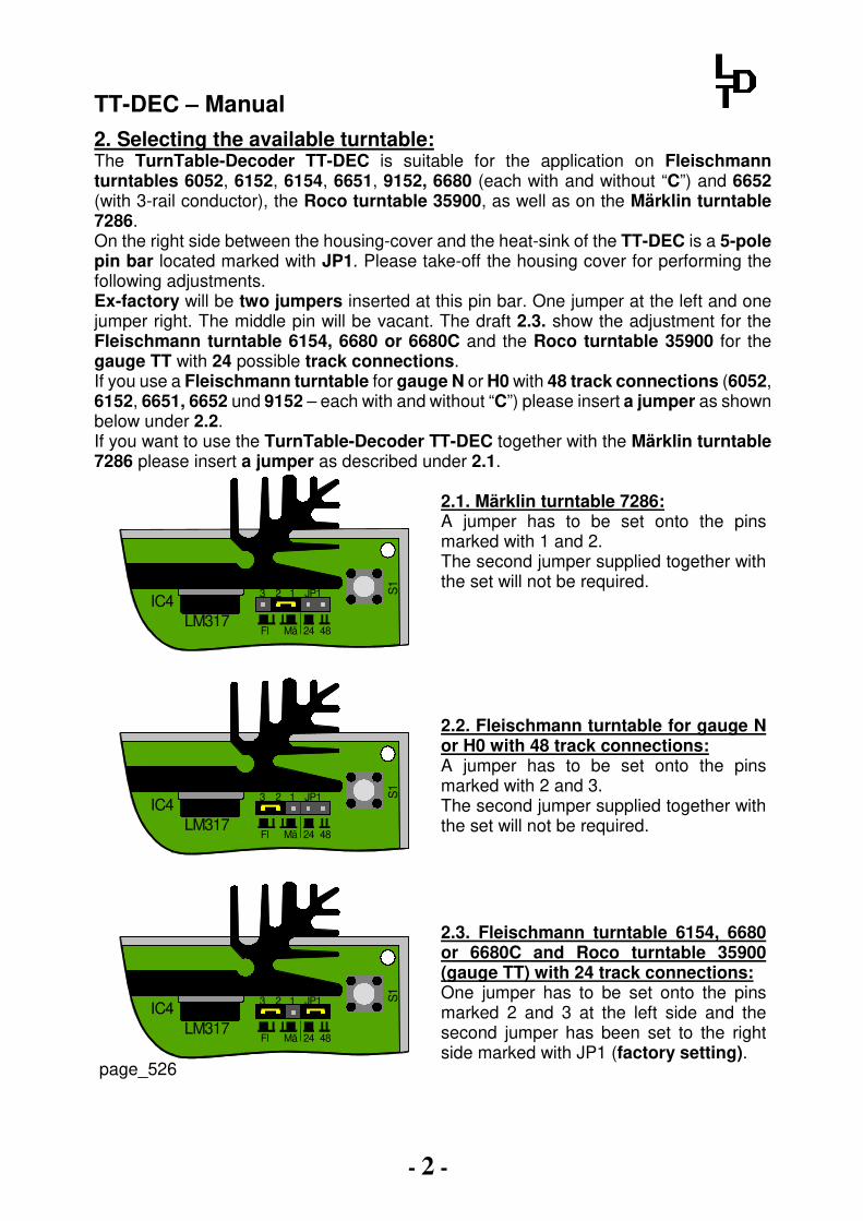
2. Selecting the available turntable:
The TurnTable-Decoder TT-DEC is suitable for the application on Fleischmann turntables 6052, 6152, 6154, 6651, 9152, 6680 (each with and without “C”) and 6652 (with 3-rail conductor), the Roco turntable 35900, as well as on the Märklin turntable 7286. On the right side between the housing-cover and the heat-sink of the TT-DEC is a 5-pole pin bar located marked with JP1. Please take-off the housing cover for performing the following adjustments. Ex-factory will be two jumpers inserted at this pin bar. One jumper at the left and one jumper right. The middle pin will be vacant. The draft 2.3. show the adjustment for the Fleischmann turntable 6154, 6680 or 6680C and the Roco turntable 35900 for the gauge TT with 24 possible track connections. If you use a Fleischmann turntable for gauge N or H0 with 48 track connections (6052, 6152, 6651, 6652 und 9152 – each with and without “C”) please insert a jumper as shown below under 2.2. If you want to use the TurnTable-Decoder TT-DEC together with the Märklin turntable 7286 please insert a jumper as described under 2.1.
LM317IC4
S1
JP1123
LM317IC4
S1
JP1123
LM317IC4
S1
JP1123
24 48MäFl
24 48MäFl
24 48MäFl
page_526
2.1. Märklin turntable 7286: A jumper has to be set onto the pins marked with 1 and 2. The second jumper supplied together with the set will not be required.
2.2. Fleischmann turntable for gauge N or H0 with 48 track connections: A jumper has to be set onto the pins marked with 2 and 3. The second jumper supplied together with the set will not be required.
2.3. Fleischmann turntable 6154, 6680 or 6680C and Roco turntable 35900 (gauge TT) with 24 track connections: One jumper has to be set onto the pins marked 2 and 3 at the left side and the second jumper has been set to the right side marked with JP1 (factory setting).
TT-DEC – Manual
- 3 -
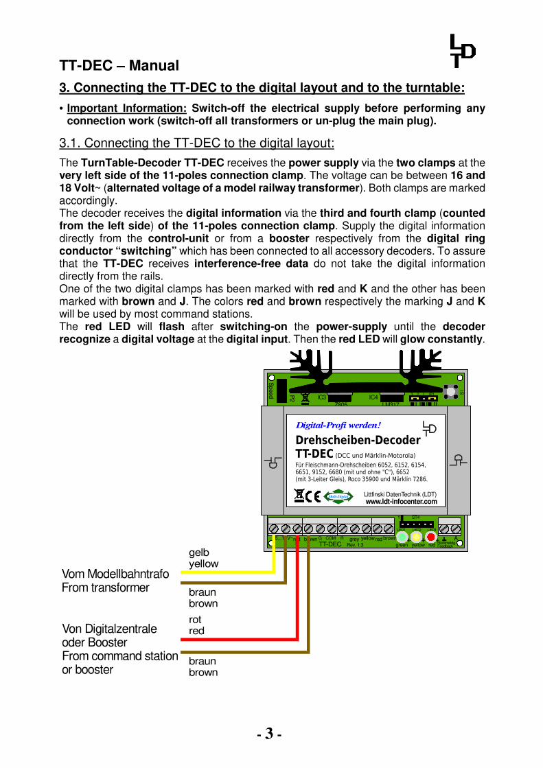
3. Connecting the TT-DEC to the digital layout and to the turntable:
• Important Information: Switch-off the electrical supply before performing any connection work (switch-off all transformers or un-plug the main plug).
3.1. Connecting the TT-DEC to the digital layout:
The TurnTable-Decoder TT-DEC receives the power supply via the two clamps at the very left side of the 11-poles connection clamp. The voltage can be between 16 and 18 Volt~ (alternated voltage of a model railway transformer). Both clamps are marked accordingly. The decoder receives the digital information via the third and fourth clamp (counted from the left side) of the 11-poles connection clamp. Supply the digital information directly from the control-unit or from a booster respectively from the digital ring conductor “switching” which has been connected to all accessory decoders. To assure that the TT-DEC receives interference-free data do not take the digital information directly from the rails. One of the two digital clamps has been marked with red and K and the other has been marked with brown and J. The colors red and brown respectively the marking J and K will be used by most command stations. The red LED will flash after switching-on the power-supply until the decoder recognize a digital voltage at the digital input. Then the red LED will glow constantly.
Von Digitalzentraleoder BoosterFrom command stationor booster
braunbrown
Vom ModellbahntrafoFrom transformer
gelbyellow
rotred
braunbrown
Z805 LM317
K J
LED1
+red brown
ST4
IC3
+ +LED2 LED3
grey yellowred brownRev. 1.3
16...18V~ G COM R
TT-DEC
1
ARückmeldg.Feedback
Speed P
2 IC4
S1
JP1123
green yellow red
Für Fleischmann-Drehscheiben 6052, 6152, 6154,6651, 9152, 6680 (mit und ohne "C"), 6652 (mit 3-Leiter Gleis), Roco 35900 und Märklin 7286.
Drehscheiben-DecoderTT-DEC (DCC und Märklin-Motorola)
Digital-Profi werden!
Littfinski DatenTechnik (LDT)Multi-Digital
www.ldt-infocenter.com

TT-DEC – Manual
- 4 -
3.2. Connecting the TT-DEC to a Fleischmann turntable 6052, 6152, 6154, 6651, 6652, 9152 or 6680 (each with and without “C”) and Roco turntable 35900:
All Fleischmann turntables and the Roco turntable 35900 contain a 5-poles flat ribbon cable. The two yellow wires on the right side are for the supply to both bridge rails. For a simple connection this wires can be connected to the digital ring conductor “drive”. If you want to change the polarity of the bridge rails automatically via the TurnTable-Decoder TT-DEC (problems of the reverse loop by bridge turning of 180º) the two wires have to get the digital current supply from a permanent power switch unit DSU (DauerStromUmschalter). Additional information is available within the chapter “Change the bridge track polarity on Fleischmann turntables”.
The red, gray and yellow wire of the 5-poles flat ribbon cable has to be connected to the clamps “red”, “gray” and “yellow” of the TT-DEC as indicated within the sketch.
The manual turntable switch, supplied together with the Fleischmann turntable, shall not be connected in this case.
page_519
Von Digitalzentraleoder BoosterFrom command station or booster
braunbrown
Vom ModellbahntrafoFrom transformer
gelbyellow
rotred
braunbrown
Fleischmann DrehscheibeFleischmann Turntable
BühnengleisVon Digitalzentrale oder BoosterTurntable bridge trackFrom command station or booster
Z805 LM317
K J
LED1
+red brown
ST4
IC3
+ +LED2 LED3
grey yellowred brownRev. 1.3
16...18V~ G COM R
TT-DEC
1
ARückmeldg.Feedback
Speed P
2 IC4
S1
JP1123
green yellow red
Für Fleischmann-Drehscheiben 6052, 6152, 6154,6651, 9152, 6680 (mit und ohne "C"), 6652 (mit 3-Leiter Gleis), Roco 35900 und Märklin 7286.
Drehscheiben-DecoderTT-DEC (DCC und Märklin-Motorola)
Digital-Profi werden!
Littfinski DatenTechnik (LDT)Multi-Digital
www.ldt-infocenter.com

TT-DEC – Manual
- 5 -
page_527
If you use a Fleischmann turntable equipped with a motor from sb modellbau you have to connect the TurnTable-Decoder TT-DEC with the yellow cable by using two diodes.
3.3. Connecting the TT-DEC to the Märklin turntable 7286:
The Märklin turntable 7286 contains a 6-poles flat ribbon cable incl. plug.
Von Digitalzentraleoder BoosterFrom command stationor booster
braunbrown
Vom ModellbahntrafoFrom transformer
gelbyellow
rotred
braunbrown
braunbrown
Märklin Drehscheibe 7286Märklin Turntable 7286
Z805 LM317
K J
LED1
+red brown
ST4
IC3
+ +LED2 LED3
grey yellowred brownRev. 1.3
16...18V~ G COM R
TT-DEC
1
ARückmeldg.Feedback
Speed P
2 IC4
S1
JP1123
green yellow red
Für Fleischmann-Drehscheiben 6052, 6152, 6154,6651, 9152, 6680 (mit und ohne "C"), 6652 (mit 3-Leiter Gleis), Roco 35900 und Märklin 7286.
Drehscheiben-DecoderTT-DEC (DCC und Märklin-Motorola)
Digital-Profi werden!
Littfinski DatenTechnik (LDT)Multi-Digital
www.ldt-infocenter.com
page_501
Z805 LM317
K J
LED1
+red brown
ST4
IC3
+ +LED2 LED3
grey yellowred brownRev. 1.3
16...18V~ G COM R
TT-DEC
1
ARückmeldg.Feedback
Speed P
2 IC4
S1
JP1123
green yellow red
Für Fleischmann-Drehscheiben 6052, 6152, 6154,6651, 9152, 6680 (mit und ohne "C"), 6652 (mit 3-Leiter Gleis), Roco 35900 und Märklin 7286.
Drehscheiben-DecoderTT-DEC (DCC und Märklin-Motorola)
Digital-Profi werden!
Littfinski DatenTechnik (LDT)Multi-Digital
www.ldt-infocenter.com
Von Digitalzentraleoder BoosterFrom command stationor booster
braunbrown
Vom ModellbahntrafoFrom transformer
gelbyellow
rotred
braunbrown
BühnengleisVon Digitalzentrale oder BoosterTurntable bridge trackFrom command station or booster
9,1V Z-DiodenBestellbezeichnung: ZPY9V19,1V Z-DiodesOrder code: ZPY9V1
TT-DEC – Manual
- 6 -
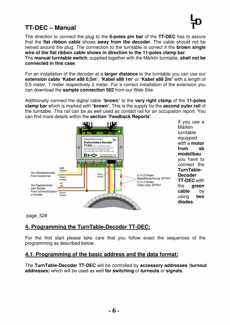
The direction to connect the plug to the 6-poles pin bar of the TT-DEC has to assure that the flat ribbon cable shows away from the decoder. The cable should not be twined around the plug. The connection to the turntable is correct if the brown single wire of the flat ribbon cable shows in direction to the 11-poles clamp bar. The manual turntable switch, supplied together with the Märklin turntable, shall not be connected in this case. For an installation of the decoder at a larger distance to the turntable you can use our extension cable “Kabel s88 0,5m”, “Kabel s88 1m“ or “Kabel s88 2m” with a length of 0.5 meter, 1 meter respectively 2 meter. For a correct installation of the extension you can download the sample connection 502 from our Web-Site. Additionally connect the digital cable “brown” to the very right clamp of the 11-poles clamp bar which is marked with “brown”. This is the supply for the second outer rail of the turntable. This rail can be as well used as contact rail for an occupation report. You can find more details within the section “Feedback Reports”.
Von Digitalzentraleoder BoosterFrom command stationor booster
braunbrown
Vom ModellbahntrafoFrom transformer
gelbyellow
rotred
braunbrown
braunbrown
Z805 LM317
K J
LED1
+red brown
ST4
IC3
+ +LED2 LED3
grey yellowred brownRev. 1.3
16...18V~ G COM R
TT-DEC
1
ARückmeldg.Feedback
Speed P
2 IC4
S1
JP1123
green yellow red
Für Fleischmann-Drehscheiben 6052, 6152, 6154,6651, 9152, 6680 (mit und ohne "C"), 6652 (mit 3-Leiter Gleis), Roco 35900 und Märklin 7286.
Drehscheiben-DecoderTT-DEC (DCC und Märklin-Motorola)
Digital-Profi werden!
Littfinski DatenTechnik (LDT)Multi-Digital
www.ldt-infocenter.com
9,1V Z-DiodenBestellbezeichnung: ZPY9V19,1V Z-DiodesOrder code: ZPY9V1
page_528
If you use a Märklin turntable equipped with a motor from sb modellbau you have to connect the TurnTable-Decoder TT-DEC with the green cable by using two diodes.
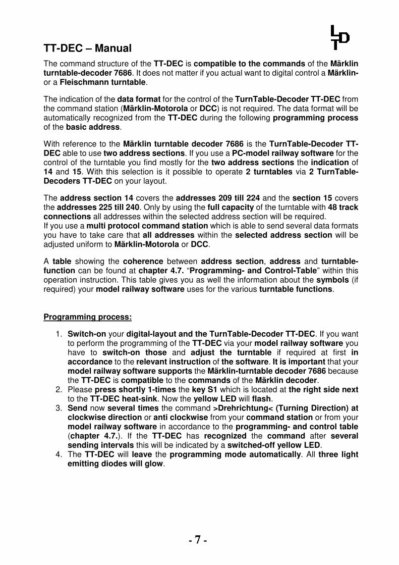
4. Programming the TurnTable-Decoder TT-DEC: For the first start please take care that you follow exact the sequences of the programming as described below. 4.1. Programming of the basic address and the data format: The TurnTable-Decoder TT-DEC will be controlled by accessory addresses (turnout addresses) which will be used as well for switching of turnouts or signals.
TT-DEC – Manual
- 7 -
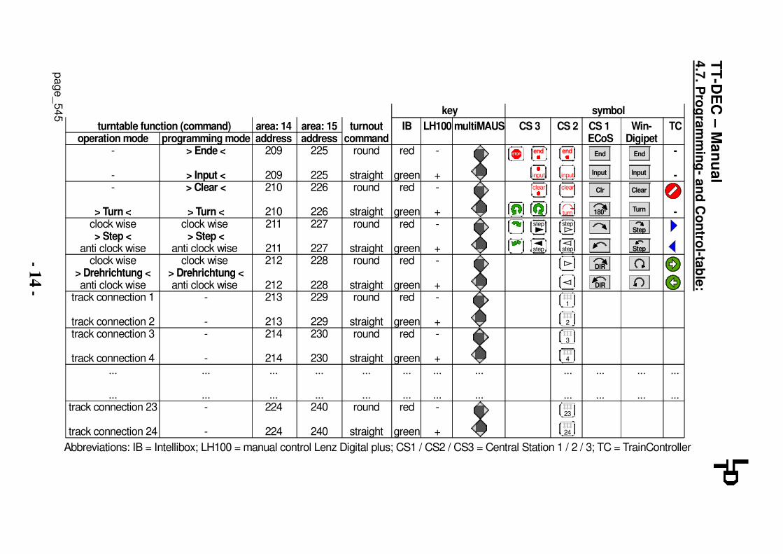
The command structure of the TT-DEC is compatible to the commands of the Märklin turntable-decoder 7686. It does not matter if you actual want to digital control a Märklin- or a Fleischmann turntable. The indication of the data format for the control of the TurnTable-Decoder TT-DEC from the command station (Märklin-Motorola or DCC) is not required. The data format will be automatically recognized from the TT-DEC during the following programming process of the basic address. With reference to the Märklin turntable decoder 7686 is the TurnTable-Decoder TT-DEC able to use two address sections. If you use a PC-model railway software for the control of the turntable you find mostly for the two address sections the indication of 14 and 15. With this selection is it possible to operate 2 turntables via 2 TurnTable-Decoders TT-DEC on your layout. The address section 14 covers the addresses 209 till 224 and the section 15 covers the addresses 225 till 240. Only by using the full capacity of the turntable with 48 track connections all addresses within the selected address section will be required. If you use a multi protocol command station which is able to send several data formats you have to take care that all addresses within the selected address section will be adjusted uniform to Märklin-Motorola or DCC. A table showing the coherence between address section, address and turntable-function can be found at chapter 4.7. “Programming- and Control-Table” within this operation instruction. This table gives you as well the information about the symbols (if required) your model railway software uses for the various turntable functions. Programming process:
1. Switch-on your digital-layout and the TurnTable-Decoder TT-DEC. If you want to perform the programming of the TT-DEC via your model railway software you have to switch-on those and adjust the turntable if required at first in accordance to the relevant instruction of the software. It is important that your model railway software supports the Märklin-turntable decoder 7686 because the TT-DEC is compatible to the commands of the Märklin decoder.
2. Please press shortly 1-times the key S1 which is located at the right side next to the TT-DEC heat-sink. Now the yellow LED will flash.
3. Send now several times the command >Drehrichtung< (Turning Direction) at clockwise direction or anti clockwise from your command station or from your model railway software in accordance to the programming- and control table (chapter 4.7.). If the TT-DEC has recognized the command after several sending intervals this will be indicated by a switched-off yellow LED.
4. The TT-DEC will leave the programming mode automatically. All three light emitting diodes will glow.
TT-DEC – Manual
- 8 -
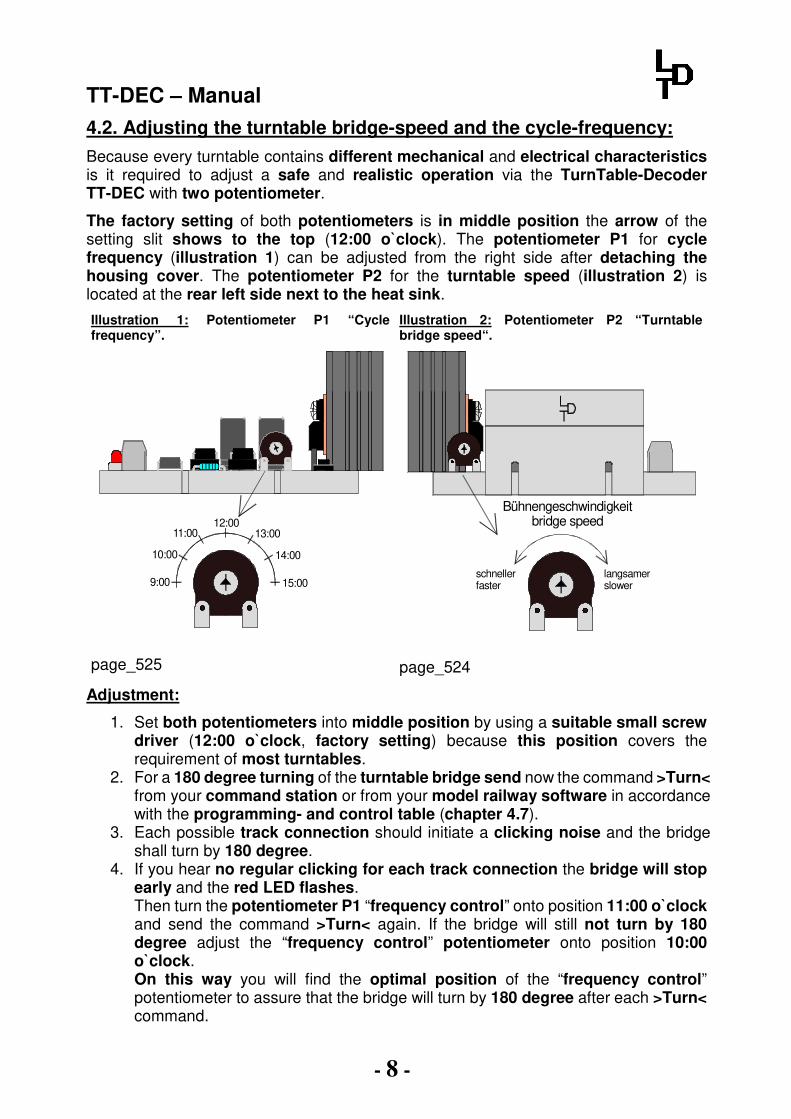
4.2. Adjusting the turntable bridge-speed and the cycle-frequency:
Because every turntable contains different mechanical and electrical characteristics is it required to adjust a safe and realistic operation via the TurnTable-Decoder TT-DEC with two potentiometer.
The factory setting of both potentiometers is in middle position the arrow of the setting slit shows to the top (12:00 o`clock). The potentiometer P1 for cycle frequency (illustration 1) can be adjusted from the right side after detaching the housing cover. The potentiometer P2 for the turntable speed (illustration 2) is located at the rear left side next to the heat sink.
Illustration 1: Potentiometer P1 “Cycle frequency”.
Illustration 2: Potentiometer P2 “Turntable bridge speed“.
12:0011:00
10:00
9:00 15:00
14:00
13:00
page_525
schnellerfaster
langsamerslower
Bühnengeschwindigkeitbridge speed
page_524
Adjustment:
1. Set both potentiometers into middle position by using a suitable small screw driver (12:00 o`clock, factory setting) because this position covers the requirement of most turntables.
2. For a 180 degree turning of the turntable bridge send now the command >Turn< from your command station or from your model railway software in accordance with the programming- and control table (chapter 4.7).
3. Each possible track connection should initiate a clicking noise and the bridge shall turn by 180 degree.
4. If you hear no regular clicking for each track connection the bridge will stop early and the red LED flashes. Then turn the potentiometer P1 “frequency control” onto position 11:00 o`clock and send the command >Turn< again. If the bridge will still not turn by 180 degree adjust the “frequency control” potentiometer onto position 10:00 o`clock. On this way you will find the optimal position of the “frequency control” potentiometer to assure that the bridge will turn by 180 degree after each >Turn< command.
TT-DEC – Manual
- 9 -
5. With the potentiometer P2 “turntable bridge speed” is it possible to change the turning speed of the bridge. The clicking of each track connection shall be audible. Change the turning direction of the bridge with the command >Drehrichtung< (turning direction) and correct the turning speed with the potentiometer P2.
6. Control: After further >turn< commands in both directions with and without locomotive the turntable bridge should turn each time by 180 degree to the same track connection. If necessary repeat the adjustment as described under 1 to 5 with a little higher turning speed. If the turning bridge is turning generally unevenly please check the mechanical components of your turntable.
4.3. Programming track connections:
Please attend: The adjustment of the turntable bridge speed and the cycle frequency has to be completed in accordance to section 4.2 to assure a reliable turning of the turntable bridge by 180 degree by each >Turn< command in both turning directions before starting with the programming of the track connections.
By programming the track connections you should prepare your TurnTable-Decoder TT-DEC to be able to recognize all available track connections and turn the turntable bridge to the required track connection during the operation. During the programming process please define one track connection as track 1 as a so-called reference track. Programming process:
1. Press shortly the key S1 2 times. The green LED flashes. 2. Send now the command >Input<. The red LED will be shortly switched-off and
the turntable bridge turns eventually to the last programmed reference track. 3. Turn now the turntable bridge with the commands >Step< (clockwise or anti
clockwise) to the track 1 (reference track). 4. Send now the command >Clear< to store the position track 1 (reference track).
The red LED will be switched-off shortly. 5. Turn the turntable bridge with the command >Step< clockwise to the next
required track connection. Please consider eventually as well single opposite track connections.
6. Store the track connection with the command >input<. The red LED will be switched-off shortly.
7. Prepare further track connections on the same way. 8. If you have completed the programming of all track connections send the
command >End<. The turntable bridge will turn to track 1 (reference track) and the programming mode will be automatically finalized. If the turntable bridge will not return to the defined reference track you have to repeat the programming process.
TT-DEC – Manual
- 10 -
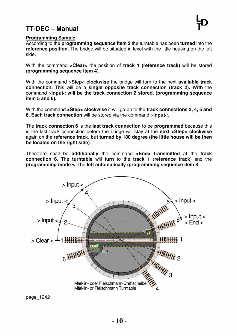
Programming Sample According to the programming sequence item 3 the turntable has been turned into the reference position. The bridge will be situated in level with the little housing on the left side. With the command >Clear< the position of track 1 (reference track) will be stored (programming sequence item 4). With the command >Step< clockwise the bridge will turn to the next available track connection. This will be a single opposite track connection (track 2). With the command >Input< will be the track connection 2 stored. (programming sequence item 5 and 6). With the command >Step< clockwise it will go-on to the track connections 3, 4, 5 and 6. Each track connection will be stored via the command >Input<. The track connection 6 is the last track connection to be programmed because this is the last track connection before the bridge will stay at the next >Step< clockwise again on the reference track, but turned by 180 degree (the little house will be then be located on the right side). Therefore shall be additionally the command >End< transmitted at the track connection 6. The turntable will turn to the track 1 (reference track) and the programming mode will be left automatically (programming sequence item 8).
Märklin- oder Fleischmann-DrehscheibeMärklin- or Fleischmann Turntable
1
3> Input <5
> Input <> End <6
1
2
3
4
6
2
4> Input <
> Input <
> Input <
> Clear <
page_1242

TT-DEC – Manual
- 11 -
4.4. Change the bridge track polarity on Fleischmann and Roco turntables:
If Fleischmann or the Roco turntables 35900 will be used on a digital layout with 2-conductor track the four track contacts of the bridge, which connect electrically the bridge track with the track, shall be removed. Alternatively is it possible to isolate each rail on both sides behind the track connections. If the bridge track has been electrically separated from the track connections by using one of the above methods is the constant supply with digital current of all tracks to the turntable possible. A constant supply of the tracks with digital current can be recommended because on this way is it possible to switch specific loc-functions on or off even inside the locomotive shed. But if the turntable bridge turns by 180 degree there will be a short circuit in case the polarity of the bridge track will not be adapted to the polarity of the contacted track connections. The TurnTable-Decoder TT-DEC is able to change the polarity of the bridge rail. For this purpose will be the TurnTable-Decoder combined with a permanent power switch unit (DauerStromUmschalter) DSU. The permanent power switch unit DSU has to be connected with the clamps “G”, “COM” and “R” to the TurnTable-Decoder TT-DEC as shown at the below sample connection. The bridge track receives digital current via the DSU.
page_523
Von Digitalzentraleoder BoosterRingleitung "Schalten"From command station or boosterRing conductor "switching"
braunbrown
Vom ModellbahntrafoFrom transformer
gelbyellow
rotred
braunbrown
Fleischmann DrehscheibeFleischmann Turntable
Dauer Strom Umschalter DSUPermanent power switch unit DSU
Von Digitalzentraleoder BoosterRingleitung "Fahren"From command station or boosterRing conductor "driving"
Z805 LM317
K J
LED1
+red brown
ST4
IC3
+ +LED2 LED3
grey yellowred brownRev. 1.3
16...18V~ G COM R
TT-DEC
1
ARückmeldg.Feedback
Speed P
2 IC4
S1
JP1123
green yellow red
Für Fleischmann-Drehscheiben 6052, 6152, 6154,6651, 9152, 6680 (mit und ohne "C"), 6652 (mit 3-Leiter Gleis), Roco 35900 und Märklin 7286.
Drehscheiben-DecoderTT-DEC (DCC und Märklin-Motorola)
Digital-Profi werden!
Littfinski DatenTechnik (LDT)Multi-Digital
www.ldt-infocenter.com
Com RG
DS
UR
ev. 3.0Littfinski D
atenTechnik
KL2KL1
KL3
Relais
TT-DEC – Manual
- 12 -
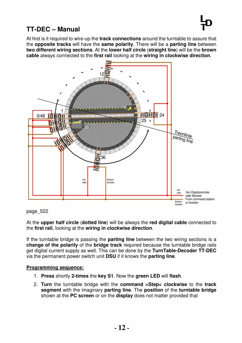
At first is it required to wire-up the track connections around the turntable to assure that the opposite tracks will have the same polarity. There will be a parting line between two different wiring sections. At the lower half circle (straight line) will be the brown cable always connected to the first rail looking at the wiring in clockwise direction.
1
12
2425
36
0/48
Trennlinieparting line
Von Digitalzentraleoder BoosterFrom command station or booster
rotred
braunbrown
rotred
braunbrown
page_522
At the upper half circle (dotted line) will be always the red digital cable connected to the first rail, looking at the wiring in clockwise direction. If the turntable bridge is passing the parting line between the two wiring sections is a change of the polarity of the bridge track required because the turntable bridge rails get digital current supply as well. This can be done by the TurnTable-Decoder TT-DEC via the permanent power switch unit DSU if it knows the parting line. Programming sequence:
1. Press shortly 2-times the key S1. Now the green LED will flash.
2. Turn the turntable bridge with the command >Step< clockwise to the track segment with the imaginary parting line. The position of the turntable bridge shown at the PC screen or on the display does not matter provided that
TT-DEC – Manual
- 13 -
the adjustments will be carried out via your model railway software or via your command station with turntable indication.
3. Send the command >Drehrichtung< (turning direction) clockwise or anti clockwise. The position of changing the polarity will be stored and the programming mode will be closed. The turntable bridge will turn automatically to the track connection 1.
4. Control: Send the command >Turn<. If the turntable bridge is passing the parting line the red LED will shortly switch off. If already a permanent power switch unit (DSU) for the change of polarity of the bridge track has been installed to the TT-DEC the relay of the DSU relay will give a click.
4.5. Synchronizing the reference track: If the indication of the turntable bridge position of the model railway software or on the display of the command station does not conform to the real position of the turntable bridge is it possible to carry out a synchronization process.
Synchronization process:
1. Press shortly 1 time the key S1. The yellow LED will flash. 2. Turn the turntable bridge with the commands >Step< (clockwise or anti
clockwise) to the track 1 (reference track). The position of the turntable indicated on the PC screen or on the display does not matter.
3. Send the command: turn directly to track 1. The turntable bridge does not turn. The turntable symbol on the screen or on the display indicates now also track 1. If the position of the control housing is not correct please send again the command turn directly to track 1.
4. Send now the command >Drehrichtung< (turn direction) clockwise or anti clockwise. The synchronization process is now completed and the yellow LED will be switched off.
4.6. Special function: Turntable test / Factory setting: 4.6.1. Turntable test: Press the programming key S1 approx. 4 seconds until the red LED will switch off. The bridge will turn by 360 degree after releasing the key and will stop shortly on each programmed track connection. 4.6.2. Factory setting: If the programming-key S1 will be depressed for 2 seconds during switching-on the TT-DEC, all adjustments will be deleted and the factory setting will be restored (basic address 225, data format DCC, all 24 respectively 48 track connections are programmed in accordance to the adjusted type of turntable re. chapter 2).
TT
-DE
C –
Ma
nu
al
- 14
-
4.7
. Pro
gra
mm
ing
- an
d C
on
trol-ta
ble
:
STOP
area: 14address
209
209210
210211
211212
212213
213214
214...
...224
224
operation mode-
--
> Turn <clock wise> Step <
anti clock wiseclock wise
> Drehrichtung <anti clock wise
track connection 1
track connection 2track connection 3
track connection 4...
...track connection 23
track connection 24
IB
red
greenred
greenred
greenred
greenred
greenred
green...
...red
green
turnoutcommand
round
straightround
straightround
straightround
straightround
straightround
straight...
...round
straight
area: 15address
225
225226
226227
227228
228229
229230
230...
...240
240
programming mode> Ende <
> Input <> Clear <
> Turn <clock wise
> Step <anti clock wise
clock wise > Drehrichtung <anti clock wise
-
--
-...
...-
-
turntable function (command) LH100
-
+-
+-
+-
+-
+-
+...
...-
+
multiMAUS
...
...
Abbreviations: IB = Intellibox; LH100 = manual control Lenz Digital plus; CS1 / CS2 / CS3 = Central Station 1 / 2 / 3; TC = TrainController
DIR
DIR
180°
Clr
Input
End
...
...
CS 1 ECoS
End
Clear
Input
Turn
Win-Digipet
TC
-
-
-
CS 2
...
...
...
...
Step
Step
symbolkey
CS 3
end
input
clear
turn
step
step
1
2
3
4
23
24
...
...
end
input
clear
step
step
page_545

TT-DEC – Manual
- 15 -
5. Feedback reports:
The Turntable-Decoder TT-DEC is able to send the information “position reached” and “bridge track occupied” to the feedback modules. Those feedback information can be used by a digital command station or a model railway software for further automatic control operation of the turntable.
After the turntable bridge reaches the wanted position the TurnTable-Decoder TT-DEC creates a feedback signal on the 2-poles clamp KL5 marked with “feedback” for the evaluation of the model railway software.
The information “bridge track occupied” will be realized by the 3-conductor rail via a contact rail (one isolated bridge rail) and by the 2-conductor rail via a track occupancy report by use of current measurement.
With reference to the installed turntable and digital system there will be different feedback modules used for the two feedback information “position reached” and “bridge track occupied”.
The (colored) wiring samples on the following pages and further samples for the thematic feedback can be found as well on our Web-site at the section “sample connections” for the Turntable-Decoder TT-DEC.
5.1. Feedback Reports with the Märklin turntable (3-conductor rails):
5.1.1. Position reached and bridge track occupied with standard Feedback Module RM-88-N for the s88-Feedback bus:
page_830 Position reached and bridge track occupied with RM-88-N
Von Digitalzentraleoder BoosterFrom command stationor booster
braunbrown
Vom ModellbahntrafoFrom transformer
gelbyellow
rotred
braunbrown
braunbrown
Märklin Drehscheibe 7286Märklin Turntable 7286
Z805 LM317
K J
LED1
+red brown
ST4
IC3
+ +LED2 LED3
grey yellowred brownRev. 1.3
16...18V~ G COM R
TT-DEC
1
ARückmeldg.Feedback
Speed P
2 IC4
S1
JP1123
green yellow red
Für Fleischmann-Drehscheiben 6052, 6152, 6154,6651, 9152, 6680 (mit und ohne "C"), 6652 (mit 3-Leiter Gleis), Roco 35900 und Märklin 7286.
Drehscheiben-DecoderTT-DEC (DCC und Märklin-Motorola)
Digital-Profi werden!
Littfinski DatenTechnik (LDT)Multi-Digital
www.ldt-infocenter.com
IN
109 11 8765432112 13 14 15 16
KL6 KL5 KL4 KL3 KL2 KL1
Littfinski DatenTechnik (LDT)
ST2ST1
Rückmeldemodul RM-88-N16 - channel feedback module Rev. 1.0
BU1 BU2s88-N
OUT IN
s88-N
OUT
Digital-Profi werden!
www.ldt-infocenter.comLittfinski DatenTechnik (LDT)
16 Rückmeldeeingänge für dens88-Rückmeldebus.
RückmeldemodulRM-88-N
s88-N

TT-DEC – Manual
- 16 -
5.1.2. Position reached and bridge track occupied with Optocoupling-Feedback Module RM-88-N-O for the s88-Feedback bus:
Position reached and bridge track occupied with RM-88-N-O
5.2. Feedback reports with Fleischmann turntables and Roco turntable 35900 (2-conductor rails):
5.2.1. Position reached and bridge track occupied with RM-GB-8-N for the s88-Feedback bus:
Position reached and turntable bridge occupied with RM-GB-8-N
page_638
page_831
Z805 LM317
K J
LED1
+red brown
ST4
IC3
+ +LED2 LED3
grey yellowred brownRev. 1.3
16...18V~ G COM R
TT-DEC
1
ARückmeldg.Feedback
Speed P
2 IC4
S1JP1123
green yellow red
Für Fleischmann-Drehscheiben 6052, 6152, 6154,6651, 9152, 6680 (mit und ohne "C"), 6652 (mit 3-Leiter Gleis), Roco 35900 und Märklin 7286.
Drehscheiben-DecoderTT-DEC (DCC und Märklin-Motorola)
Digital-Profi werden!
Littfinski DatenTechnik (LDT)Multi-Digital
www.ldt-infocenter.com
Von Digitalzentraleoder BoosterFrom command stationor booster
braunbrown
Vom ModellbahntrafoFrom transformer
gelbyellow
rotred
braunbrown
braunbrown
Märklin Drehscheibe 7286Märklin Turntable 7286
IN
109 11 8765432112 13 14 15 16
KL6 KL5 KL4 KL3 KL2 KL1
ST2ST1
Rückmeldemodul RM-88-N-Opto16 - channel feedback module Rev. 1.0
Ref
BU1 BU2s88-N
OUT IN
s88-N
OUT
Littfinski DatenTechnik (LDT)
16 galvanisch getrennte Rückmeldeeingängefür den s88-Rückmeldebus.
RückmeldemodulRM-88-N-Opto
Digital-Profi werden!
Littfinski DatenTechnik (LDT)www.ldt-infocenter.com
s88-N
Diode 1N4003Bestellbezeichnung: 1N4003Diode 1N4003Order code: 1N4003
Überwachte Bereiche imUmfeld der Drehscheibe
monitored areas within turntable
8-fach Rückmeldemodulmit Gleisbesetztmeldern8-fold feedback modulewith occupancy detectors
RM-GB-8-NRev. 1.1
1 2 3 4 5 6 7 8IN1 IN2
IN
ST2ST1s88-N
OUT IN
s88-N
OUT
BU1 BU2
8-fach Rückmeldemodul mit integrierten Gleisbelegtmeldern für den s88-Rückmeldebus. 8-fold feedback module with occupancy detectors for s88-feedback bus.
RM-GB-8-NRückmeldemodul / Feedback module
Littfinski DatenTechnik (LDT)
Digital-Profi werden!
s88-Nwww.ldt-infocenter.com
Com RG
DS
UR
ev. 3.0Littfinski D
atenTechnik
KL2KL1
KL3
Relais
Z805 LM317
K J
LED1
+red brown
ST4
IC3
+ +LED2 LED3
grey yellowred brownRev. 1.3
16...18V~ G COM R
TT-DEC
1
ARückmeldg.Feedback
Speed P
2 IC4
S1
JP1123
green yellow red
Für Fleischmann-Drehscheiben 6052, 6152, 6154,6651, 9152, 6680 (mit und ohne "C"), 6652 (mit 3-Leiter Gleis), Roco 35900 und Märklin 7286.
Drehscheiben-DecoderTT-DEC (DCC und Märklin-Motorola)
Digital-Profi werden!
Littfinski DatenTechnik (LDT)Multi-Digital
www.ldt-infocenter.com
Von Digitalzentraleoder BoosterRingleitung "Schalten"From command stationor boosterRing conductor "switching"
braunbrown
Vom ModellbahntrafoFrom transformer
gelbyellow
rotred
braunbrown
Fleischmann DrehscheibeFleischmann Turntable
Dauer Strom Umschalter DSUPermanent power switch unit DSU
braunbrown J
rotredK
rotred
� �
rotred
�
Von Digitalzentraleoder BoosterRingleitung "Fahren"From command stationor boosterRing conductor "driving"
Diode 1N4003 Bestellbezeichnung: 1N4003Diode 1N4003 Order code: 1N4003
Widerstand 1,5KOhm /0,6WBestellbezeichnung: Res1K5Resistor 1,5KOhm /0,6WOrder code: Res1K5
TT-DEC – Manual
- 17 -
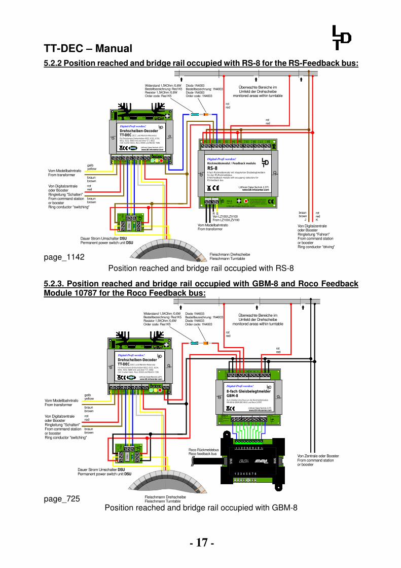
5.2.2 Position reached and bridge rail occupied with RS-8 for the RS-Feedback bus:
Position reached and bridge rail occupied with RS-8
5.2.3. Position reached and bridge rail occupied with GBM-8 and Roco Feedback Module 10787 for the Roco Feedback bus:
5 6 7 8 J K
Littfinski DatenTechnik (LDT)GBM-8
J 1 2 3 4K
Zu d
en G
leis
en
To the tra
cks
5 6 7 8+ 1 2 3 4 +
Rev. 1.08-fach Gleisbelegt-melderOctal occupancydetector
Zum direkten Anschluss an die RückmeldemoduleRM-88-N-O/RM-DEC-88-O und Roco 10787.
8-fach GleisbelegtmelderGBM-8
Digital-Profi werden!
www.ldt-infocenter.comLittfinski DatenTechnik (LDT)
Von Digitalzentraleoder BoosterRingleitung "Schalten"From command stationor boosterRing conductor "switching"
braunbrown
Vom ModellbahntrafoFrom transformer
gelbyellow
rotred
braunbrown
Fleischmann DrehscheibeFleischmann Turntable
Dauer Strom Umschalter DSUPermanent power switch unit DSU
rotred
� �
rotred
�Diode 1N4003 Bestellbezeichnung: 1N4003Diode 1N4003 Order code: 1N4003
Widerstand 1,5KOhm /0,6WBestellbezeichnung: Res1K5Resistor 1,5KOhm /0,6WOrder code: Res1K5
10787
BU
S
87654321
++
BU
S
87654321
Von Zentrale oder Booster From command station or booster
Roco RückmeldebusRoco feedback bus
Überwachte Bereiche imUmfeld der Drehscheibe
monitored areas within turntable
Com RG
DS
UR
ev. 3.0Littfinski D
atenTechnik
KL2KL1
KL3
Relais
Z805 LM317
K J
LED1
+red brown
ST4
IC3
+ +LED2 LED3
grey yellowred brownRev. 1.3
16...18V~ G COM R
TT-DEC
1
ARückmeldg.Feedback
Speed P
2 IC4
S1
JP1123
green yellow red
Für Fleischmann-Drehscheiben 6052, 6152, 6154,6651, 9152, 6680 (mit und ohne "C"), 6652 (mit 3-Leiter Gleis), Roco 35900 und Märklin 7286.
Drehscheiben-DecoderTT-DEC (DCC und Märklin-Motorola)
Digital-Profi werden!
Littfinski DatenTechnik (LDT)Multi-Digital
www.ldt-infocenter.com
Position reached and bridge rail occupied with GBM-8
page_725
page_1142
Überwachte Bereiche imUmfeld der Drehscheibe
monitored areas within turntable
8-fach Rückmeldemodulmit Gleisbesetztmeldern8-fold feedback modulewith occupancy detectors
RS-8Rev. 3.2
1 2 3 4 5 6 7 8IN1 IN2
LED1
J K J K
Littfinski DatenTechnik (LDT)R S14 ..18V~S1
KL7 KL8
8-fach Rückmeldemodul mit integrierten Gleisbelegtmeldern für den RS-Rückmeldebus.8-fold feedback module with occupancy detectors for RS-feedback bus.
RS-8Rückmeldemodul / Feedback module
Digital-Profi werden!
Littfinski DatenTechnik (LDT)www.ldt-infocenter.com
Com RG
DS
UR
ev. 3.0Littfinski D
atenTechnik
KL2KL1
KL3
Relais
Z805 LM317
K J
LED1
+red brown
ST4
IC3
+ +LED2 LED3
grey yellowred brownRev. 1.3
16...18V~ G COM R
TT-DEC
1
ARückmeldg.Feedback
Speed P
2 IC4
S1
JP1123
green yellow red
Für Fleischmann-Drehscheiben 6052, 6152, 6154,6651, 9152, 6680 (mit und ohne "C"), 6652 (mit 3-Leiter Gleis), Roco 35900 und Märklin 7286.
Drehscheiben-DecoderTT-DEC (DCC und Märklin-Motorola)
Digital-Profi werden!
Littfinski DatenTechnik (LDT)Multi-Digital
www.ldt-infocenter.com
Von Digitalzentraleoder BoosterRingleitung "Schalten"From command stationor boosterRing conductor "switching"
braunbrown
Vom ModellbahntrafoFrom transformer
gelbyellow
rotred
braunbrown
Fleischmann DrehscheibeFleischmann Turntable
Dauer Strom Umschalter DSUPermanent power switch unit DSU
braunbrown J
rotredK
rotred
� �
rotred
�
Von Digitalzentraleoder BoosterRingleitung "Fahren"From command stationor boosterRing conductor "driving"
Diode 1N4003 Bestellbezeichnung: 1N4003Diode 1N4003 Order code: 1N4003
Widerstand 1,5KOhm /0,6WBestellbezeichnung: Res1K5Resistor 1,5KOhm /0,6WOrder code: Res1K5
R SVon LZ100/LZV100From LZ100/LZV100
Vom ModellbahntrafoFrom transformer

TT-DEC – Manual
- 18 -
5.2.4. Position reached and bridge rail occupied with Uhlenbrock 63 340 for the LocoNet:
page_860 Position reached and bridge rail occupied with Uhlenbrock 63 340
Diode 1N4003 Bestellbezeichnung: 1N4003Diode 1N4003 Order code: 1N4003
Widerstand 1,5KOhm /0,6WBestellbezeichnung: Res1K5Resistor 1,5KOhm /0,6WOrder code: Res1K5
Überwachte Bereiche imUmfeld der Drehscheibe
monitored areas within turntable
Dig
italspg
für 2-Leiter Gleis mit Gleisbesetztmelder und Spannungsüberwachung
Rückmeldemodul
Uhlenbrockdigital
R
63 340
Gleis 1
Gleis 2
Gleis 3
Gleis 4
Gleis 5
Gleis 6
Gleis 7
Gleis 8
Ko
ntro
ll-LE
D
Prg
-Taster Fahrstrom
max. 3A
Com RG
DS
UR
ev. 3.0Littfinski D
atenTechnik
KL2KL1
KL3
Relais
Z805 LM317
K J
LED1
+red brown
ST4
IC3
+ +LED2 LED3
grey yellowred brownRev. 1.3
16...18V~ G COM R
TT-DEC
1
ARückmeldg.Feedback
Speed P
2 IC4
S1
JP1123
green yellow red
Für Fleischmann-Drehscheiben 6052, 6152, 6154,6651, 9152, 6680 (mit und ohne "C"), 6652 (mit 3-Leiter Gleis), Roco 35900 und Märklin 7286.
Drehscheiben-DecoderTT-DEC (DCC und Märklin-Motorola)
Digital-Profi werden!
Littfinski DatenTechnik (LDT)Multi-Digital
www.ldt-infocenter.com
Von Digitalzentraleoder BoosterRingleitung "Schalten"From command stationor boosterRing conductor "switching"
braunbrown
Vom ModellbahntrafoFrom transformer
gelbyellow
rotred
braunbrown
Fleischmann DrehscheibeFleischmann Turntable
Dauer Strom Umschalter DSUPermanent power switch unit DSU
braunbrown J
rotredK
rotred
� � �
Von Digitalzentraleoder BoosterRingleitung "Fahren"From command stationor boosterRing conductor "driving"
Loconet
rotred
TT-DEC – Manual
- 19 -
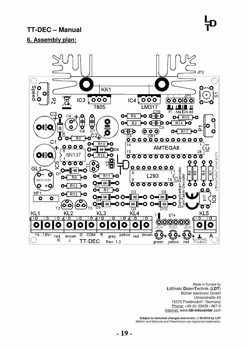
6. Assembly plan:
Made in Europe by Littfinski DatenTechnik (LDT)
Bühler electronic GmbH Ulmenstraße 43
15370 Fredersdorf / Germany Phone: +49 (0) 33439 / 867-0
Internet: www.ldt-infocenter.com
Subject to technical changes and errors. 06/2019 by LDT Märklin and Motorola and Fleischmann are registered trademarks.