Littelfuse Startco PGR-5701 Ground Fault Monitor With Variable
26
Littelfuse Startco PGR-5701 Ground Fault Monitor With Variable Frequency Drive Test Report by Ross George, E.I.T. Technical Sales Merv Savostianik, P.Eng. Sales Engineering Manager Mike Vangool, P.Eng. Research and Development Engineer Littelfuse Startco 3714 Kinnear Place Saskatoon, SK S7P 0A6 (306) 373-5505
Transcript of Littelfuse Startco PGR-5701 Ground Fault Monitor With Variable
Littelfuse Startco
PGR-5701 Ground Fault Monitor
With
Variable Frequency Drive
Test Report
by
Ross George, E.I.T. Technical Sales
Merv Savostianik, P.Eng. Sales Engineering Manager
Mike Vangool, P.Eng. Research and Development Engineer
Littelfuse Startco
3714 Kinnear Place
Saskatoon, SK S7P 0A6
(306) 373-5505

3714 Kinnear Place Saskatoon, SK S7P 0A6 Canada
www.startco.ca
2
Executive Summary
Littelfuse Startco has conducted witness testing of the PGR-5701 Ground-Fault Monitor. The PGR-5701 was tested for use upstream (line side) of a variable-frequency drive (VFD) to verify its ability to detect a ground fault downstream (load side) of the VFD. The test system included of a 3-phase source connected to a delta-wye transformer. The transformer-secondary neutral was connected to a 200-ohm neutral-grounding resistor. The 480-V three-phase output of the transformer was connected to a VFD which was used to drive a small motor. The transformer-to-VFD connection, VFD-to-motor connection, and neutral-grounding-resistor connection were monitored using PGR-5701 Ground-Fault Monitors and PGC-3082 Current Transformers. The connection diagram is shown in Fig. 1. To configure the VFD for the testing, it was necessary to remove or disconnect various phase-to-ground capacitors because they were not rated for line-to-line voltage which is present during a bolted ground fault on a resistance-grounded system. The removal of these capacitors was not in the manual included with the drive; instructions were obtained from the manufacturer’s technical support group. This test shows that a PGR-5701 at each of the CT locations is capable of detecting a ground fault on the VFD-to-motor connection. Therefore, in VFD applications it is recommended that the CT and PGR-5701 be located upstream of the drive—this connection will detect a ground fault in the supply cable to the VFD, in the VFD, and downstream of the VFD. Additional testing was also performed to evaluate the performance of the PGR-5701 with ground faults of various currents at other locations in the system.

3714 Kinnear Place Saskatoon, SK S7P 0A6 Canada
www.startco.ca
3
Table of Contents Executive Summary ............................................................................................................ 2 Table of Contents ................................................................................................................ 3 Introduction ......................................................................................................................... 4
Background ......................................................................................................................... 5
Test Circuit ...................................................................................................................... 5
Ground-Fault Apparatus ................................................................................................. 7
Equipment ..................................................................................................................... 10
Controllable Variables .................................................................................................. 11
Data ............................................................................................................................... 12
Procedure .......................................................................................................................... 12
Measurements ............................................................................................................... 12
Initial Test ..................................................................................................................... 13
Variable-Frequency Testing .......................................................................................... 14
DC Bus Fault Testing .................................................................................................... 15
Upstream Fault Testing ................................................................................................. 17
Fault Current and Line-Side Leakage ........................................................................... 19
Analysis............................................................................................................................. 19
Initial Test Results ........................................................................................................ 19
Variable-Frequency Results .......................................................................................... 20
DC Bus Fault Results .................................................................................................... 22
Upstream Fault Results ................................................................................................. 22
Fault-Current and Line-Side-Leakage Results .............................................................. 23
Limitations .................................................................................................................... 23
Conclusion ........................................................................................................................ 24

3714 Kinnear Place Saskatoon, SK S7P 0A6 Canada
www.startco.ca
3
This page intentionally blank.

3714 Kinnear Place Saskatoon, SK S7P 0A6 Canada
www.startco.ca
4
Introduction
The microprocessor-based PGR-5701 uses an external zero-sequence current
transformer (CT) and selectable DFT or peak-detection algorithms to detect ground-
fault current. This testing was completed to verify the ability of the PGR-5701 to
detect a ground fault downstream of a VFD with the CT located upstream of the
drive.
The tests were performed at the Littelfuse Startco facility in Saskatoon, Canada.
A test circuit was devised to allow the PGR-5701 to be tested at several locations in
the circuit and under various operating conditions. Testing was done with a variable-
resistance ground-fault placed on the drive connection to the motor, at the VFD dc
bus, and at the supply transformer-secondary terminals. The tests involved varying
the drive output frequency such that a frequency response for the PGR-5701 could be
observed for frequencies up to 60 Hz. Frequencies above 60 Hz were not tested, as
the response of the PGR-5701 peak filter is the same from 60 to above 400 Hz. As
frequencies this high are uncommon in industrial applications, testing was deemed
unnecessary.

3714 Kinnear Place Saskatoon, SK S7P 0A6 Canada
www.startco.ca
5
Background
Test Circuit
The test circuit was a test-bench version of a typical industrial VFD installation,
with the addition of ground-fault relays. The circuit was connected as shown in
Fig. 1.
Figure 1. Circuit Schematic
The test circuit included a three-phase variable-voltage ac input, connected to a
delta-wye 240:600-V, 3-kVA step-up transformer. Utilizing the variable-voltage
input, the transformer was configured for 480-Vac line-to-line at the wye
secondary. See Fig.2.

3714 Kinnear Place Saskatoon, SK S7P 0A6 Canada
www.startco.ca
6
Figure 2. Incoming power supply
The transformer neutral was connected to a 200-ohm neutral-grounding resistor
(NGR) in series with a power analyzer and a root-mean-square (RMS) ammeter.
This circuit passed through a PGC-3082 zero-sequence current transformer which
was connected to a PGR-5701 Ground-Fault Monitor (analog output A1). See
Fig.3.
Figure 3. Transformer, NGR, and RMS Ammeter

3714 Kinnear Place Saskatoon, SK S7P 0A6 Canada
www.startco.ca
7
The transformer secondary was connected to the VFD. The output of the VFD
was connected to 100 feet of 3C#10 Teck cable, which was connected to a ½ hp
three-phase motor. The circuits from the transformer to the VFD and the VFD to
the motor passed through PGC-3082 zero-sequence current transformers which
were connected to PGR-5701 Ground-Fault monitors (analog outputs A2 and A3).
See Fig. 4.
Figure 4. VFD, Teck Cable, Variable Resistor and Motor
Ground-Fault Apparatus A variable-resistance ground-fault apparatus was used to place a ground-fault on
the system. The schematic of the apparatus circuit is shown in Fig.5.

3714 Kinnear Place Saskatoon, SK S7P 0A6 Canada
www.startco.ca
8
The apparatus consisted of a variable resistance with a 0 to 2850 ohm range
connected in series with a power analyzer and an RMS ammeter. The variable
resistance can be comprised of the following components to achieve desired
resistance values:
(5) – 470 ohm resistors
(1) – 500 ohm rheostat
One end of the apparatus was connected through a push-button switch to one
phase of the power circuit and the other was connected to ground to simulate a
ground fault of various resistances. See Figs. 5 and 6. With a line-to-ground
voltage of 277 V, this apparatus allowed a ground-fault-current range from 1.385
A using only the NGR to 91 mA with all resistors connected and the rheostat set
to 500 ohms.
Figure 5. Ground-Fault Apparatus Schematic

3714 Kinnear Place Saskatoon, SK S7P 0A6 Canada
www.startco.ca
9
Figure 6. Variable Ground-Fault Resistor
Ground connections for ammeters and motor chassis bond were connected to a
ground point on the VFD chassis. The VFD chassis was connected to the building
ground, as shown in Figs. 7 and 8.
Figure 7. Grounding Diagram

3714 Kinnear Place Saskatoon, SK S7P 0A6 Canada
www.startco.ca
10
Figure 8. Ground Connections at VFD Chassis
Equipment The equipment used during the test is listed in Table 1. Variac Superior Electric Variable Autotransformer A219111-008 Current Transformers PGC-3082, 5:0.05-A, 82 mm ID Transformer Hammond 240:600V 3kVA Transformer NGR Dale RH-250 250 W 100 Ohm Resistor (x2) Ammeters Fluke 87, Fluke 87 V Voltage Output Recorder HIOKI 8808 Memory HiCorder Power Analyzer Yokogawa WT500 Power Analyzer Motor Westinghouse FD78 ½ HP 3-Phase Motor Cable 100 ft 3C#10 TECK Variable Frequency Drive 480 V 3-Phase 20 HP Table 1. Equipment List

3714 Kinnear Place Saskatoon, SK S7P 0A6 Canada
www.startco.ca
11
Figure 9. Connected Test Circuit
Controllable Variables
In order to simulate the power system and provide valid results, the test circuit
was able to simulate a variety of conditions. There were several controllable
parameters which are listed in Table 2.
Variables Settings
Output Frequency of VFD 0 – 320 Hz (0.01 Hz increments) Ground-Fault Resistance 0 – 2850 Ohms
PGR-5701 Filter Selection Fixed or Variable Frequency PGR-5701 Trip Level 5 mA – 4.95 A
(5 mA increments, 1 – 99%) Fault location Upstream or Downstream of VFD, VFD dc
bus, and supply-transformer termination. Table 2. Controllable Test Parameters

3714 Kinnear Place Saskatoon, SK S7P 0A6 Canada
www.startco.ca
12
Data In order to analyze the operation of the system, data was collected from the RMS
ammeters, power analyzer, and oscilloscope as well as the PGR-5701 Ground-
Fault Monitor trip and analog outputs. This data will verify the ability of a PGR-
5701 to operate correctly in a VFD application.
Procedure
Measurements Measurements were recorded from the two RMS ammeters and the outputs of the
three PGR-5701 monitors. The PGR-5701 analog output is a 0-5 V voltage output
linearly representing the 0-100% rating of CT-primary current. When connected
to a PGC-3082, the analog-output scaling is 1 mV per 1 mA of measured current.
Non-filtered and filtered ground-fault (EL1) and NGR (EL2) currents and
voltages were measured by the power analyzer. See Figs 1 and 5. The power
analyzer has an internal selectable 500 Hz low-pass filter. Application of the filter
was necessary as the unfiltered signals contained large amounts of noise, making
waveforms difficult to visualize. This is seen in an example ground-fault with a 1-
A fault current at 10-Hz fundamental frequency. See Figs. 10 and 11.

3714 Kinnear Place Saskatoon, SK S7P 0A6 Canada
www.startco.ca
13
Figure 10. 10 Hz 1 A Fault, wide band Figure 11. 10 Hz 1 A Fault, 500 Hz Filter
From top to bottom, the waveforms are; line-to-ground voltage, ground-fault
current, NGR voltage, and NGR current.
Initial Test An initial test with the VFD operating at 60 Hz was completed. This test was
repeated using both PGR-5701 fixed frequency (DFT) and variable frequency
(peak-detection) filters. A downstream ground fault was applied to the system
(point GF1 in Fig.1.) and all three PGR-5701 Ground-Fault Monitors tripped,
with very similar analog-output values as shown in Table 3.
Table 3. Initial Test, Load-Side Fault, 60 Hz
The unfiltered currents measured by the power analyzer, EL2 NF and EL1 NF,
are similar to the values of the Fluke RMS meters, while the power analyzer
filtered values, EL2 and EL1, are similar to the PGR-5701 analog output values.
The waveforms in Figs. 12 and 13 were captured for the filtered and unfiltered
fault currents from the power analyzer.
Frequency Filter
Setting Fluke 87 EL2 EL2 NF Fluke 87 EL1 EL1 NF A1 A2 A3
60 DFT 326 254 316 255 251 251 24360 PEAK 295 247 296 280 247 294 264 268 263
NGR Current (mA) Fault Current (mA)PGR-5701 Analog Output (mV)
Load-Side Fault

3714 Kinnear Place Saskatoon, SK S7P 0A6 Canada
www.startco.ca
14
It can be seen from the waveform captures that the fault current contains many
harmonic components. With the 500 Hz filter applied, a 180-Hz ripple current can
be seen superimposed over the 60-Hz drive output. This 180-Hz ripple current
was observed in all subsequent tests at various output frequencies.
Figure 12. 60 Hz 300 mA Fault, wide-band Filter Figure 13. 60 Hz 300 mA Fault, 500 Hz Filter
Variable-Frequency Testing Tests performed using various frequencies generated by the VFD were completed
using both the DFT and peak-detection filters to demonstrate PGR-5701
performance with each filter when monitoring a system with frequencies within
the range of 10 to 60 Hz. In these tests, all three PGR-5701 monitors were set to
trip at 5%, corresponding to a ground-fault current of 250 mA. At the selected
frequencies, the fault current was increased until all three PGR-5701 units tripped;
the current values at the trip point were recorded. See Table 4.
3714 Kinnear Place Saskatoon, SK S7P 0A6 Canada
www.startco.ca
15
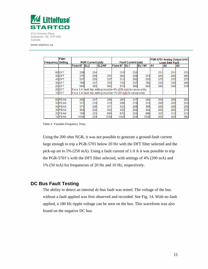
Table 4. Variable-Frequency Tests
Using the 200 ohm NGR, it was not possible to generate a ground-fault current
large enough to trip a PGR-5701 below 20 Hz with the DFT filter selected and the
pick-up set to 5% (250 mA). Using a fault current of 1.0 A it was possible to trip
the PGR-5701’s with the DFT filter selected, with settings of 4% (200 mA) and
1% (50 mA) for frequencies of 20 Hz and 10 Hz, respectively.
DC Bus Fault Testing The ability to detect an internal dc-bus fault was tested. The voltage of the bus
without a fault applied was first observed and recorded. See Fig. 14. With no fault
applied, a 180 Hz ripple voltage can be seen on the bus. This waveform was also
found on the negative DC bus.

3714 Kinnear Place Saskatoon, SK S7P 0A6 Canada
www.startco.ca
16
Figure 14. Positive DC Bus to Ground Voltage, No Fault
With a 500 mA fault applied to the negative bus (point GF2 in Fig. 1.) the
following waveforms were recorded.
Figure 15. Negative DC Bus 500mA fault
The ripple current is in the fault as well as through the NGR, with a sizeable DC
offset. Fault data is shown in Table 5.
3714 Kinnear Place Saskatoon, SK S7P 0A6 Canada
www.startco.ca
17
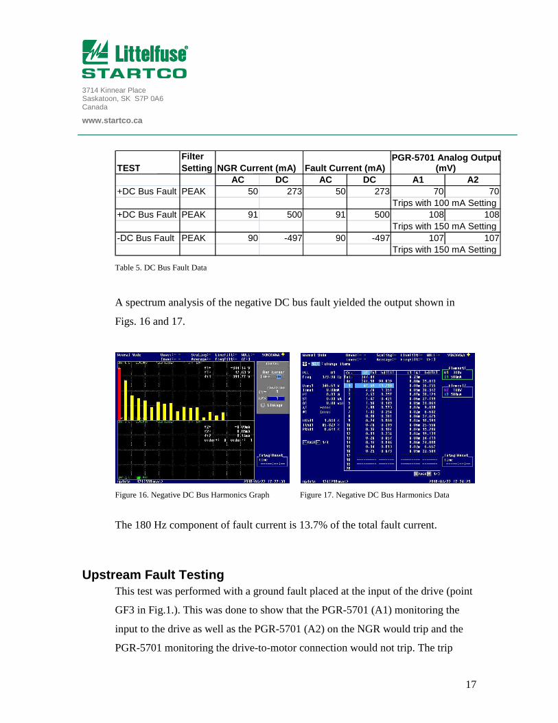
Table 5. DC Bus Fault Data
A spectrum analysis of the negative DC bus fault yielded the output shown in
Figs. 16 and 17.
Figure 16. Negative DC Bus Harmonics Graph Figure 17. Negative DC Bus Harmonics Data
The 180 Hz component of fault current is 13.7% of the total fault current.
Upstream Fault Testing This test was performed with a ground fault placed at the input of the drive (point
GF3 in Fig.1.). This was done to show that the PGR-5701 (A1) monitoring the
input to the drive as well as the PGR-5701 (A2) on the NGR would trip and the
PGR-5701 monitoring the drive-to-motor connection would not trip. The trip
TESTFilter Setting NGR Current (mA) Fault Current (mA)
AC DC AC DC A1 A2+DC Bus Fault PEAK 50 273 50 273 70 70
Trips with 100 mA Setting+DC Bus Fault PEAK 91 500 91 500 108 108
Trips with 150 mA Setting-DC Bus Fault PEAK 90 -497 90 -497 107 107
Trips with 150 mA Setting
PGR-5701 Analog Output (mV)

3714 Kinnear Place Saskatoon, SK S7P 0A6 Canada
www.startco.ca
18
levels of A1 and A2 were set to 5% (250 mA) and A3 was set to 1% (50 mA.)
Currents were recorded at the point where both A1 and A2 had functioned at each
frequency.
Table 6. Fault Testing at VFD Input
While A3 shows values of over 50 mV, it did not trip during any of the tests.
The test was then repeated with the fault located upstream of PGR-5701 A2 (point
GF4 in Fig.1). PGR-5701’s A2 and A3 were set to 1% (50 mA), while A1 was set
at 5% (250 mA). The ground-fault current was gradually increased until A1
tripped at each frequency.
Table 7. Fault testing upstream of A2
Regardless of frequency, A1 would trip while A2 and A3 would not.
FrequencyFilter Setting
PGR-5701 #3
NGR Current Fault Current A1 NGR Current Fault Current A2 A3No Fault Outputs, Drive ON. 92 92 74
60 PEAK 249 236 238 258 246 241 8150 PEAK 251 236 239 259 245 238 8040 PEAK 252 237 239 260 245 237 7330 PEAK 251 237 240 259 245 238 8020 PEAK 252 237 241 258 243 240 7710 PEAK 253 237 237 262 247 244 76
PGR-5701 #1 Measuring NGR Current PGR-5701 #2 Measuring GF Current on Input of Drive
FrequencyFilter Setting
PGR-5701#2
PGR-5701#3
NGR Current Fault Current A1 A2 A3No Fault Outputs, Drive ON. 92 92 74
60 PEAK 251 238 241 95 8050 PEAK 252 237 239 91 7740 PEAK 251 236 240 94 7730 PEAK 252 237 238 90 8020 PEAK 252 237 239 91 8010 PEAK 253 238 239 92 77
PGR-5701 #1 Measuring NGR Current

3714 Kinnear Place Saskatoon, SK S7P 0A6 Canada
www.startco.ca
19
Fault Current and Line-Side Leakage A comparison of the line-side leakage relative to fault current was completed in
order to see what affect fault current has on leakage on the line side of the drive.
This test was used to simulate a fault upstream of the line feeding the drive. In
this test a ground fault was placed at the transformer secondary terminals (point
GF4 in Fig. 1.), with varying current and the output of the PGR-5701 (A2) on the
VFD input was recorded. See Table 8.
Table 8. Upstream Fault Current and PGR-5701 Output
The PGR-5701 was set at 50mA and in all cases did not trip.
Analysis
Initial Test Results The initial test proved the capability of the PGR-5701 to detect a ground fault
located at the load side of a VFD, with a zero-sequence CT located at any of three
different positions in the circuit.
Min Max0 71 90
100 70 93200 68 81300 71 97400 70 96500 90 112 600 79 113 700 84 116 800 83 124 900 87 106
1000 85 107
Analog Output of PGR-5701System Fault Current (mA)

3714 Kinnear Place Saskatoon, SK S7P 0A6 Canada
www.startco.ca
20
The PGR-5701’s monitoring the line side of the VFD, the load side of the VFD
and the NGR showed nearly identical outputs. These outputs were very similar to
the ones measured by the power analyzer with the 500 Hz low-pass filter selected.
Testing with both DFT and peak filters yielded similar values with the drive
output at 60 Hz. It can be seen during the peak-filter test that the current detected
by the RMS ammeters is similar to the current measured by the power analyzer
with no filter selected; both include all frequencies present in the current signal.
This test has proven that zero-sequence currents on the load side of a VFD are not
isolated from the line side of the VFD. The zero-sequence current is equally
detectable by a PGC-3082 at the NGR, the VFD line side, and the load side.
Variable-Frequency Results Testing of the PGR-5701 at various fault frequencies was completed using both
the DFT and peak filter selection of the PGR-5701. The results show that the
bandwidth of the DFT filter is too narrow to be used in VFD applications in
which the VFD operates below 50 Hz. The peak filter is a better choice in this
type of application—its wider filter bandwidth allows the PGR-5701 to detect
frequencies below 50 Hz. Even with the peak detection filter, frequencies below
50 Hz are attenuated. This frequency response is shown in Fig. 18.

3714 Kinnear Place Saskatoon, SK S7P 0A6 Canada
www.startco.ca
21
Figure 18. PGR-5701 Frequency Response, Peak Detection Filter
From Fig. 18 a recommended setting for the PGR-5701 can be calculated based
on the lowest expected operational frequency. This setting can be found by
multiplying the desired trip level by the normalized response value at the lowest
expected operational frequency.
Recommended setting = (desired trip level) x (response @ lowest frequency)
For instance, if a 1,000-mA RMS trip level is desired and the VFD will be
operating at 40 Hz, the recommended PGR-5701 setting is 1,000 mA x 0.8 =
800 mA, or 16%.

3714 Kinnear Place Saskatoon, SK S7P 0A6 Canada
www.startco.ca
22
DC Bus Fault Results When a fault was placed on the VFD DC bus, the fault current had a predominant
DC component with a smaller 180 Hz AC component as well as some harmonics
of 180 Hz. The 180-Hz component is created by the VFD’s full-wave rectifier
“front end”. A current transformer is unable to detect the DC component of the
fault; however because of the sizeable 180-Hz component, it is possible for a
PGR-5701 to detect this type of fault.
The DC fault spectrum analysis in Fig. 17. shows the 180 Hz amounts to 10-15%
of the fault. Therefore, if it is desired to have a PGR-5701 trip on a DC-bus fault
it is recommended that the pickup level be set to 10% of the NGR let-through
current. (This assumes that the measured-feeder charging current is less than 10%
of the NGR let-through current, or the PGR-5701 could sympathetic trip when a
ground fault occurs elsewhere on the system.)
Upstream Fault Results When a fault is located upstream of the monitoring PGC-3082, the PGR-5701
does not trip. This shows that the PGR-5701 does not detect an upstream fault.
The PGR-5701’s which were downstream of the fault were set to their lowest
setting of 1%, corresponding to a 50 mA trip level. While it was noticed that the
outputs of the PGR-5701 showed levels of up to 95 mV, the relays did not trip,
and this is the desired response.

3714 Kinnear Place Saskatoon, SK S7P 0A6 Canada
www.startco.ca
23
Fault-Current and Line-Side-Leakage Results With a ground fault located upstream, a CT measures the charging current of the
feeder downstream. This test was performed to determine what affect upstream-
fault magnitude has on the measured charging current.
Figure 19. Line-Side Leakage vs System Fault Current
As can be seen in Fig. 19, an increase in upstream fault current has only a very
slight effect on the level of charging current. The increase in charging current was
not substantial enough to trip a PGR-5701.
Limitations As these tests were conducted under lab settings, they were created to best
simulate systems in the field. However, it is impossible to create a direct analogue
to applications in the field. During these tests the system was operated with only
one VFD fed by a dedicated input. The ½ hp motor was unloaded, and the NGR
of 200 ohms limited the current of the fault to 1.38 A. These tests were performed
over the course of two days at room temperature, in an indoor lab and therefore
cannot simulate all possible conditions that may be experienced in a field
application over a long period of time.

3714 Kinnear Place Saskatoon, SK S7P 0A6 Canada
www.startco.ca
24
Conclusion Each PGR-5701, one each upstream and downstream of the VFD and one at the
NGR, measured an equal amount of VFD-frequency zero-sequence current when
a ground-fault was applied on the load side of the VFD. This proves that the VFD
does not isolate zero-sequence current, and that a PGR-5701 placed at the line or
load side of the drive will detect the same amount of zero-sequence current. A
PGR-5701 placed upstream of a VFD is capable of monitoring the feeder, VFD,
and the load downstream of the CT.
When a PGR-5701 is used in a variable-frequency application, use the peak
(variable-frequency) filter selection. This selection has a wider pass band and less
attenuation at frequencies below 60 Hz. When used in these applications, a lower
trip setting for the lower frequencies can be required due to the PGR-5701
frequency response. The lowest operating frequency expected should be
considered and the normalized pick-up value from Fig. 18 should be used to
calculate the appropriate trip level.
A DC bus fault can be detected by a PGR-5701 monitoring upstream of the VFD.
The DC component is not detected, but the 180 Hz ripple current can be. The
180 Hz component is roughly 10-15% of the total fault current. Therefore, it is
necessary to have the PGR-5701 set at a level of roughly 10% of the NGR let-
through current in order to detect a DC bus fault. (The reduction in setting applies
at this location only. Monitors upstream and on the NGR may require a higher
setting as they will measure accumulated system harmonics.)
When a fault is located upstream of a monitoring CT, the current is not detected
by that PGR-5701. This shows that if a fault is located on the line side of, or

3714 Kinnear Place Saskatoon, SK S7P 0A6 Canada
www.startco.ca
25
inside of a VFD, with a PGR-5701 connected on the load side of the drive, the
fault is not detected.
The effects of fault-current magnitude with a fault at the transformer terminals
were examined. This showed that when a fault is upstream of the CT, such as on
another drive fed by the same feeder, that the PGR-5701’s will not trip. The
change in charging current was minimal and the PGR-5701’s did not trip.