List of Models (Temperature Sensors) @ C-N 196 C to 450 C ASTM316L Enclosed terminals 6 E52-P @ B-N...
53
CSM_E52_DS_E_21_5 1 Temperature Sensor E52 A Wide Variety of High-precision Temperature Sensors • Previous models with M3 screw connections have been joined by new models with ferrules to help reduce wiring work. • A Temperature Sensor for Packaging Machines that accurately measures seal temperature has been added. • The type, shape, length, and terminal shape can be selected to match the temperature to be measured, location, and environment. Ordering Information ■ List of Models (Temperature Sensors) Note: 1. Exclusive models are provided on the following page. 2. These tables provide general specifications only. Be sure to read the detailed specifications and precautions before use. 3. The temperature range varies with the material, thickness, construction, and element type of the protective tubing. Classifi- cation Description Model and appearance Tempera- ture range (See note 3.) Ele- ment type Conduc- tor type Class Protective tubing material Terminal type Page General- purpose Models Sheathed platinum re- sistance thermome- ter E52-P@AY −196°C to 450°C Pt100 3-conduc- tor system B SUS316 Exposed lead wires 5 E52-P@C-N −196°C to 450°C ASTM316L Enclosed terminals 6 E52-P@B-N Exposed terminals Standard platinum re- sistance thermometer E52-P@C-N 0°C to 450°C SUS316 Enclosed terminals 7 Sheathed thermocou- ple E52-CA@AY E52-IC@AY 0°C to 900°C K (CA) J (IC) Non- grounded type 2 (0.75) ASTM316L Exposed lead wires 9 to 12 E52-CA@B-N E52-IC@B-N Exposed terminals 13 E52-CA@C-N E52-IC@C-N Enclosed terminals Standard thermocou- ple E52-CA@B-N E52-IC@B-N SUS316 Exposed terminals 14 E52-CA@C-N E52-IC@C-N Enclosed terminals 15 E52-PR@C-N 0°C to 1,400°C R (PR) 2 (0.25) JIS ceramic JIS special ceramic Enclosed terminals 16 Low-cost Models Low-cost platinum re- sistance thermometer E52-P10AEY 0°C to 250°C Pt100 3-conduc- tor system B SUS316 Exposed lead wires 17 E52-P6DY −50°C to 250°C SUS304 E52-P6FY Low-cost thermocou- ple E52-CA@ASY E52-IC@ASY 0°C to 400°C K (CA) J (IC) Non-ground- ed type 2 (0.75) 18 E52-CA1DY E52-IC1DY Grounded type 19 E52-CA6F-N E52-CA6F-N-25 E52-IC6F-N E52-CA6D-N E52-CA6D-N-25 E52-IC6D-N 20 E52-CA10AE-N E52-IC10AE-N Non-ground- ed type Refer to Safety Precautions for All Temperature Controllers.
Transcript of List of Models (Temperature Sensors) @ C-N 196 C to 450 C ASTM316L Enclosed terminals 6 E52-P @ B-N...

CSM_E52_DS_E_21_5
1
Temperature Sensor
E52A Wide Variety of High-precision Temperature Sensors• Previous models with M3 screw connections
have been joined by new models with ferrules to help reduce wiring work.
• A Temperature Sensor for Packaging Machines that accurately measures seal temperature has been added.
• The type, shape, length, and terminal shape can be selected to match the temperature to be measured, location, and environment.
Ordering Information■ List of Models (Temperature Sensors)
Note: 1. Exclusive models are provided on the following page.2. These tables provide general specifications only. Be sure to read the detailed specifications and precautions before use.3. The temperature range varies with the material, thickness, construction, and element type of the protective tubing.
Classifi-cation
Description Model and appearance Tempera-ture range
(See note 3.)
Ele-ment type
Conduc-tor type
Class Protective tubing
material
Terminal type
Page
General-purpose Models
Sheathed platinum re-sistance thermome-ter
E52-P@AY −196°C to 450°C
Pt100 3-conduc-tor system
B SUS316 Exposed lead wires
5
E52-P@C-N −196°C to 450°C
ASTM316L Enclosed terminals
6
E52-P@B-N Exposed terminals
Standard platinum re-sistance thermometer
E52-P@C-N 0°C to 450°C SUS316 Enclosed terminals
7
Sheathed thermocou-ple
E52-CA@AYE52-IC@AY
0°C to 900°C K (CA)J (IC)
Non-grounded type
2 (0.75) ASTM316L Exposed lead wires
9 to 12
E52-CA@B-NE52-IC@B-N
Exposed terminals
13
E52-CA@C-NE52-IC@C-N
Enclosed terminals
Standard thermocou-ple
E52-CA@B-NE52-IC@B-N
SUS316 Exposed terminals
14
E52-CA@C-NE52-IC@C-N
Enclosed terminals
15
E52-PR@C-N 0°C to 1,400°C
R (PR) 2 (0.25) JIS ceramic JIS special ceramic
Enclosed terminals
16
Low-cost Models
Low-cost platinum re-sistance thermometer
E52-P10AEY 0°C to 250°C Pt100 3-conduc-tor system
B SUS316 Exposed lead wires
17
E52-P6DY −50°C to 250°C
SUS304
E52-P6FY
Low-cost thermocou-ple
E52-CA@ASYE52-IC@ASY
0°C to 400°C K (CA)J (IC)
Non-ground-ed type
2 (0.75) 18
E52-CA1DYE52-IC1DY
Grounded type
19
E52-CA6F-NE52-CA6F-N-25E52-IC6F-NE52-CA6D-NE52-CA6D-N-25E52-IC6D-N
20
E52-CA10AE-NE52-IC10AE-N
Non-ground-ed type
Refer to Safety Precautions for All Temperature Controllers.

E52
2
Note: 1. General-purpose models and low-cost models are provided on the previous page.2. These tables provide general specifications only. Be sure to read the detailed specifications and precautions before use.3. The temperature range varies with the material, thickness, construction, and element type of the protective tubing.
Use the temperature sensors with ferrule from the list on the next page.
Classifi-cation
Description Model and appearance Tempera-ture range
(See note 3.)
Ele-ment type
Conduc-tor type
Class Protective tubing
material
Terminal type
Page
Exclusive Models
Bayonet spring for molding ma-chines
E52-CA2GVYE52-IC2GVY
0°C to 350°C K (CA)J (IC)
Grounded type
2 (0.75) SUS304 Exposed lead wires
22
Crimping terminals
E52-CA1GTYE52-IC1GTY
0°C to 300°C ---
Used for measuring surface tem-peratures
E52-P2GSY −50°C to 250°C
Pt100 3-conduc-tor system
B SUS304 23
Used for room tem-perature measure-ment
E52-P10GRY −50°C to 60°C
Double-ele-ment model
E52-CA20AY-7 0°C to 900°C K (CA) Two non-grounded types
2 (0.75) ASTM316L 28
E52-P20AY-7 −196°C to 250°C
Pt100 Two 3-conductor systems
B
E52-P20C-N-7 −200°C to 450°C
Enclosed terminals
29
Waterproof model
E52-P10GPY 0°C to 70°C 3-conduc-tor system
SUS304 Exposed lead wires
23
E52-P5AY-40 −50°C to 180°C
Fluororesin tubing
25
Corrosion-resistant model
E52-P20AY-1 −80°C to 180°C
E52-CA20AY-1 0°C to 180°C K (CA) Non-grounded type
2 (0.75)
Silicone-covered lead wires
E52-CA1DY-40 0°C to 300°C Grounded type
SUS304 30
E52-CA1GTY-14 0°C to 200°C ---
Explosion-proof model
E52-P@@C-N-6 --- Pt100 3-conduc-tor system
B ASTM316L Enclosed terminals
26
E52-CA@@C-N-6 --- K (CA) Non-grounded type
2 (0.75)
Special models for packaging machines
Sheathed thermocou-ple
E52-CAAYD=1 S
0°C to 650°C K (CA) Grounded type
2 (0.75) ASTM316L Exposed lead wires
31 to 33
Thermistors E52-THE5AE52-THE6FE52-THE6D
−50°C to 300°C
Ther-mistor
Element-inter-change-able thermistor
1 SUS304 Exposed lead wires
35

3
E52
■ List of Models (Temperature Sensors with ferrule)
Note: 1. These tables provide general specifications only. Be sure to read the detailed specifications and precautions before use.2. The temperature range varies with the material, thickness, construction, and element type of the protective tubing.
■ AccessoriesIt is recommended that the following accessories be used for mounting Temperature Sensors.
Classifi-cation
Description Model and appearance Tempera-ture range
(See note 3.)
Element type
Conduc-tor type
Class Protective tubing
material
Terminal type
Page
General-purpose Models
Sheathed platinum resistance thermometer
E52-P@AF −196°C to 450°C
Pt100 3-conduc-tor system
B SUS316 Exposed lead wires
37
Sheathed thermocouple
E52-CA@AF 0°C to 900°C K (CA) Non-grounded type
2 (0.75) ASTM316L 39 to 40
Low-cost Models
Low-cost platinum resistance thermometer
E52-P10AEF 0°C to 250°C Pt100 3-conduc-tor system
B SUS316 41E52-P6DF −50°C to
250°CSUS304
E52-P6FF
Low-cost thermocouple
E52-CA1DF 0°C to 400°C K (CA) Grounded type
2 (0.75) 42
Exclusive Models
Bayonet spring for molding machines
E52-CA2GVF 0°C to 350°C K (CA) Grounded type
2 (0.75) SUS304 43
Crimping terminals
E52-CA1GTF 0°C to 300°C ---
Used for measuring surface temperatures
E52-P2GSF −50°C to 250°C
Pt100 3-conduc-tor system
B SUS304
Used for room temperature measurement
E52-P10GRF −50°C to 60°C
44
Waterproof model
E52-P10GPF 0°C to 70°C
E52-P5AF-40 −50°C to 180°C
Fluororesin tubing
45
Silicone-cov-ered lead wires
E52-CA1DF-40 0°C to 300°C K (CA) Grounded type
2 (0.75) SUS304 46
E52-CA1GTF-14 0°C to 200°C ---
Special models for packaging machines
Sheathed thermocouple
E52-CA@AFD=1 S@
0°C to 650°C K (CA) Grounded type
2 (0.75) ASTM316L 47 to 48
Accessory Temperature range
Mounting example Page
Compression Fitting
600°C max. Mounting with Compression Fitting
Note: The Compression Fitting is not of airtight construction. Do not use the Compression Fitting for applications in which the exposure of the sensing object will cause problems.
49
Loose Flange 400°C max. Mounting with Loose Flange Note: 1. Use the Loose Flange in
normal atmospheric pressure. The Loose Flange is not of airtight construction.
2. Use the Loose Flange at 400°C max.
3. Do not apply the Loose Flange to protective tubing diameters other than the applicable ones.
Compression Fitting
PT screw
Welding
Terminal box
Protective tubing
Loose FlangeMounting screw
Terminal boxProtective tubing

E52
4
General-purpose Models
■ Model Number LegendThe type of resistance thermometer, protective tubing length, and lead length can be specified as shown below.
Platinum Resistance Thermometers
1. Element typeP: Pt100
2. Protective tubing length (L)Specify the length in centimeters within the following range: Unit (cm)E52-@@AY
E52-@@B-N
E52-@@C-N
3. TerminalAY: Exposed lead wires (Y-type crimp terminal for M3.5)B-N: Exposed terminalsC-N: Enclosed terminals
4. Diameter3.2: 3.2-mm dia. (Protective tubing construction: Sheathed)
E52-@@AY and E52-@@C-N only4.8: 4.8-mm dia. (Protective tubing construction: Sheathed)
E52-@@AY and E52-@@C-N only6.4: 6.4-mm dia. (Protective tubing construction: Sheathed)
E52-@@AY and E52-@@C-N only8: 8-mm dia. (Protective tubing construction: Sheathed)
E52-@@B-N and E52-@@C-N only10: 10-mm dia. (Protective tubing construction: Standard)
E52-@@C-N only5. Heat resistance
Specify for E52-@@AY model only.6. Lead length (M)
Specify the length in meters within the following range for the E52-@@AY only:Range: 0.5, 1 to 100 m
ExamplesElement: Pt100, protective tubing length: 420 mm, exposed leads, protective tubing dia.: 4.8 mm, heat resistive, lead length: 10 m
E52-P42AY D=4.8 NETU 10M
■ Sheathed Platinum Resistance ThermometersRefer to Model Number Legend above for the Pt100.
Specifications
E52-@@@ D=@@@M1 2 3 4 5 6
Diameter (D) Length (L)3.2 7 to 1004.8 10 to 6006.4 13 to 1,300
Diameter (D) Length (L)8 20 to 100
Diameter (D) Length (L)3.2 12 to 1004.8 15 to 6006.4 18 to 1,3008 21 to 10010 26 to 100
Code Temperature range Lead type--- −20°C to 70°C
Sleeve: 0°C to 70°CVinyl-covered
NETU 0°C to 180°CSleeve: 0°C to 100°C
Glass-wool-covered, externally shielded with stainless
Element type Pt100Class JIS class BSheath material SUS316 (E52-P@AY)
ASTM316L (E52-P@B-N, E52-P@C-N)Sheath outer diameter 3.2 dia., 4.8 dia., 6.4 dia., 8 diaConductor type 3-conductor systemTemperature range −196°C to 450°C (in dry air)

5
E52Exposed-lead Models
E52-P@AYDimensions
Model InformationCustom-made models are available on request. Refer to page 4 for details.
Terminal type Protective tubing
diameter D (mm)
Protective tubing length
L (cm)
Lead wire type
Lead wire length M (m)1 2 4 8
ModelExposed-lead Models
3.2 dia. 15 Standard E52-P15AY D=3.2 1M
E52-P15AY D=3.2 2M
E52-P15AY D=3.2 4M
E52-P15AY D=3.2 8M
Heat resistive E52-P15AY D=3.2 NETU 1M
E52-P15AY D=3.2 NETU 2M
E52-P15AY D=3.2 NETU 4M
E52-P15AY D=3.2 NETU 8M
20 Standard E52-P20AY D=3.2 1M
E52-P20AY D=3.2 2M
E52-P20AY D=3.2 4M
E52-P20AY D=3.2 8M
Heat resistive E52-P20AY D=3.2 NETU 1M
E52-P20AY D=3.2 NETU 2M
E52-P20AY D=3.2 NETU 4M
E52-P20AY D=3.2 NETU 8M
35 Standard E52-P35AY D=3.2 1M
E52-P35AY D=3.2 2M
E52-P35AY D=3.2 4M
E52-P35AY D=3.2 8M
Heat resistive E52-P35AY D=3.2 NETU 1M
E52-P35AY D=3.2 NETU 2M
E52-P35AY D=3.2 NETU 4M
E52-P35AY D=3.2 NETU 8M
4.8 dia. 20 Standard E52-P20AY D=4.8 1M
E52-P20AY D=4.8 2M
E52-P20AY D=4.8 4M
E52-P20AY D=4.8 8M
Heat resistive E52-P20AY D=4.8 NETU 1M
E52-P20AY D=4.8 NETU 2M
E52-P20AY D=4.8 NETU 4M
E52-P20AY D=4.8 NETU 8M
35 Standard E52-P35AY D=4.8 1M
E52-P35AY D=4.8 2M
E52-P35AY D=4.8 4M
E52-P35AY D=4.8 8M
Heat resistive E52-P35AY D=4.8 NETU 1M
E52-P35AY D=4.8 NETU 2M
E52-P35AY D=4.8 NETU 4M
E52-P35AY D=4.8 NETU 8M
50 Standard E52-P50AY D=4.8 1M
E52-P50AY D=4.8 2M
E52-P50AY D=4.8 4M
E52-P50AY D=4.8 8M
Heat resistive E52-P50AY D=4.8 NETU 1M
E52-P50AY D=4.8 NETU 2M
E52-P50AY D=4.8 NETU 4M
E52-P50AY D=4.8 NETU 8M
6.4 dia. 20 Standard E52-P20AY D=6.4 1M
E52-P20AY D=6.4 2M
E52-P20AY D=6.4 4M
E52-P20AY D=6.4 8M
Heat resistive E52-P20AY D=6.4 NETU 1M
E52-P20AY D=6.4 NETU 2M
E52-P20AY D=6.4 NETU 4M
E52-P20AY D=6.4 NETU 8M
35 Standard E52-P35AY D=6.4 1M
E52-P35AY D=6.4 2M
E52-P35AY D=6.4 4M
E52-P35AY D=6.4 8M
Heat resistive E52-P35AY D=6.4 NETU 1M
E52-P35AY D=6.4 NETU 2M
E52-P35AY D=6.4 NETU 4M
E52-P35AY D=6.4 NETU 8M
50 Standard E52-P50AY D=6.4 1M
E52-P50AY D=6.4 2M
E52-P50AY D=6.4 4M
E52-P50AY D=6.4 8M
Heat resistive E52-P50AY D=6.4 NETU 1M
E52-P50AY D=6.4 NETU 2M
E52-P50AY D=6.4 NETU 4M
E52-P50AY D=6.4 NETU 8M
40(30) (80)
D±0.05 8 dia.
M±4% 85±10L±3%
Sleeve (SUS304)
Swage
Marking tube(Red)
Shrinkable tube(Black)
Sheath (SUS316)
Lead wireProduct Label
Marking tube(White)
White
Crimping terminal Y type for M3.5
Red
Red (A)
White (B)
Black (B)
Unit (mm)
D d l
3.2 dia. 8 404.8 dia. 8 406.4 dia. 8 40
Lead Wire• Standard (−20°C to 70°C):
Fully vinyl-covered with twelve 0.18-dia conductors (0.3 mm thick) and 4.8 mm in outer dia. The sleeve resists a temperature range between 0°C and 70°C.
• Heat Resistive (0°C to 180°C):Fully glass-wool-covered with thirty 0.12-dia. conductors (0.3 mm thick) externally shielded with stainless steel, 4 mm in outer dia. The sleeve resists a temperature range between 0°C and 100°C.
• Lead Wire Length (M): 1, 2, 4, or 8 m

E52
6
Enclosed-terminal Models
E52-P@C-NDimensionsDimensions are given in millimeters, except for the length (L), which is provided in centimeters.
Terminal box: The permissible temperature is 0°C to 90°C.
Note: 1. The terminals in the cap indicate polarity (A, B, b).2. The length L is in centimeters, but “35” is 35 millimeters.
Therefore, for the E52-P35C-N: L = 35 (cm), the sheath length L − 35 = 350 − 35 = 315 mm.
Model InformationCustom-made models are available on request. Refer to page 4 for details.
Exposed-terminal Models
E52-P@B-NDimensionsDimensions are given in millimeters, except for the length (L), which is provided in centimeters.
Note: The length L is in centimeters, but “40” is 40 millimeters. Therefore, for the E52-P35B-N: L = 35 (cm), the sheath length L − 40 = 350 − 40 = 310 mm.
Terminal type Protective tubing length
L (cm)
Protective tubing diameter D (mm)3.2 dia. 4.8 dia. 6.4 dia. 8 dia.
ModelEnclosed-terminal Models
20 E52-P20C-N D=3.2 E52-P20C-N D=4.8 E52-P20C-N D=6.4 E52-P20C-N D=835 E52-P35C-N D=3.2 E52-P35C-N D=4.8 E52-P35C-N D=6.4 E52-P35C-N D=850 E52-P50C-N D=3.2 E52-P50C-N D=4.8 E52-P50C-N D=6.4 E52-P50C-N D=875 --- E52-P75C-N D=4.8 E52-P75C-N D=6.4 ---
40(15)
(66)
(66)
58 dia.
L-35±3%
D±0.05
Product label
Socket (SUS304)
Chain
Terminal box
(Packing internal diameter : 6.5 dia)
Sheath (ASTM316L)
Cap
Swage
38G Use wiring terminals that fit M3 screws.
5.6
19.245
30.542.5
1717.6
(51)(15)
21.5
b
B
A
3×M3
L-40±3%
19 dia.
Product labelSocket (SUS304)
SwageSheath (ASTM316L)
Terminal box
8±0.05 dia.
Model InformationCustom-made models are available on request. Refer to page 4 for details
Terminal type
Protective tubing length
L (cm)
Protective tubing diameter D (mm)8 dia.Model
Exposed-terminal Models
20 E52-P20B-N D=835 E52-P35B-N D=850 E52-P50B-N D=8Terminal box: The permissible temperature is 0°C to 100°C.

7
E52
■ Standard Platinum Resistance ThermometersRefer to Model Number Legend on page 4 for the Pt100.
Specifications
Note: 1. Use the sheathed platinum resistance thermometer if condensation is likely to result.
Enclosed-terminal Models
E52-P@C-NDimensionsDimensions are given in millimeters, except for the length (L), which is provided in centimeters.
Note: 1. The length L is in centimeters, but “50” is 50 millimeters. Therefore, for the E52-P75C-N: L = 75 (cm), the protective tubing length L − 50 = 750 − 50 = 700 mm.
Terminal box: The permissible temperature is 0°C to 90°C.
Note: The terminals in the cap indicate polarity (A, B, B).
Model InformationCustom-made models are available on request. Refer to page 4 for details.
Element type Pt100Class JIS class BProtective tubing material SUS316Conductor type 3-conductor systemTemperature range 0°C to 450°C (in dry air)
Terminal type Protective tubing length L (cm)
Protective tubing diameter D (mm)
10 dia.Model
Enclosed-terminal Models
35 E52-P35C-N D=1050 E52-P50C-N D=1075 E52-P75C-N D=10100 E52-P100C-N D=10
53
(5)
(86)
(92)
82 dia.
38 dia.
L-50±3%
Chain
Cap
Terminal box
Socket (SUS304)
Protective tubing (SUS316)
(Packing internal diameter : 9 dia.)
Full-circled Welding
Product label
10±0.3 dia.
12G

E52
8
■ Model Number LegendThe type of resistance thermometer, protective tubing length, and lead length can be specified as shown below.
Thermocouples
1. Element typeCA:KIC: JPR:R
2. Protective tubing length (L)Specify the length in centimeters in the following range: Unit (cm)
E52-@@AY (Exposed-lead Model)
E52-@@B-N and E52-@@C-N (except E52-PR@C-N)
E52-PR@C-N
3. TerminalAY: Exposed lead wires (Y-type crimp terminal for M3.5)
(element type: K, J)B-N: Exposed terminals (element type: K, J)C-N: Enclosed terminals (element type: K, J, R)
4. DiameterSpecify the protective tubing material according to the table.
5. Heat resistanceSpecify this item for the exposed-lead models only.
6. Lead length (M)Specify the length in meters in the following range for the E52-@@AY only.Range: 1 to 100 m
7. Protective tubing material
ExamplesElement: K; protective tubing length: 420 mm, exposed leads, protective tubing dia.: 4.8 mm, heat resistive, lead length: 10 m
E52-CA42AY D=4.8 NETU 10M
Element: J; protective tubing length: 360 mm, enclosed terminals, protective tubing dia.: 3.2E52-IC36C-N D=3.2
E52-@@@ D=@@@M@1 2 3 4 5 6 7
Diameter (D) Length (L)1 2 to 2001.6 3 to 5003.2 5 to 2,0004.8 8 to 2,3006.4 10 to 1,2008 12 to 1,000
Diameter (D) Length (L)3.2 11 to 2,0004.8 14 to 2,3006.4 16 to 1,2008.0 18 to 1,00010 21 to 12612 24 to 12615 29 to 15622 39 to 206
Diameter (D) Length (L)15 50, 75, 100
Code Diameter (D)
Protective tubing construction
Protective tubing material
1 1 mm Sheathed ASTM316L1.6 1.6 mm Sheathed ASTM316L3.2 3.2 mm Sheathed ASTM316L4.8 4.8 mm Sheathed ASTM316L6.4 6.4 mm Sheathed ASTM316L8 8 mm Sheathed ASTM316L10 10 mm Standard SUS316, SUS310S12 12 mm Standard SUS316, SUS310S15 15 mm Standard SUS316, SUS310S
PT1, PT0 (E52-PR)22 22 mm Standard SUS316, SUS310S
Code Temperature range Lead type--- −20°C to 70°C
Sleeve: 0°C to 70°CVinyl-covered
NETU 0°C to 150°CSleeve: 0°C to 100°C
Glass-wool-covered with exter-nal shield of stainless
Code Protective tubing material
Element type
--- ASTM316L K, JSUS310S SUS310S K, D = 10 to 22PT1 JIS ceramic Cat.1 RPT0 JIS special ceramic R
9
E52
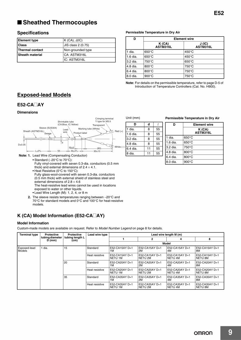
■ Sheathed ThermocouplesSpecifications Permissible Temperature in Dry Air
Note: For details on the permissible temperature, refer to page D-5 of Introduction of Temperature Controllers (Cat. No. H900).
Exposed-lead Models
E52-CA@AYDimensions
K (CA) Model Information (E52-CA@AY)Model InformationCustom-made models are available on request. Refer to Model Number Legend on page 8 for details.
Element type K (CA), J(IC)Class JIS class 2 (0.75)Thermal contact Non-grounded typeSheath material CA: ASTM316L
IC: ASTM316L
D Element wireK (CA)
ASTM316LJ (IC)
ASTM316L1 dia. 650°C 450°C1.6 dia. 650°C 450°C3.2 dia. 750°C 650°C4.8 dia. 800°C 750°C6.4 dia. 800°C 750°C8.0 dia. 900°C 750°C
Terminal type Protective tubing diameter
D (mm)
Protective tubing length L
(cm)
Lead wire type Lead wire length M (m)1 2 4 8
ModelExposed-lead Models
1 dia. 15 Standard E52-CA15AY D=1 1M
E52-CA15AY D=1 2M
E52-CA15AY D=1 4M
E52-CA15AY D=1 8M
Heat resistive E52-CA15AY D=1 NETU 1M
E52-CA15AY D=1 NETU 2M
E52-CA15AY D=1 NETU 4M
E52-CA15AY D=1 NETU 8M
20 Standard E52-CA20AY D=1 1M
E52-CA20AY D=1 2M
E52-CA20AY D=1 4M
E52-CA20AY D=1 8M
Heat resistive E52-CA20AY D=1 NETU 1M
E52-CA20AY D=1 NETU 2M
E52-CA20AY D=1 NETU 4M
E52-CA20AY D=1 NETU 8M
35 Standard E52-CA35AY D=1 1M
E52-CA35AY D=1 2M
E52-CA35AY D=1 4M
E52-CA35AY D=1 8M
Heat resistive E52-CA35AY D=1 NETU 1M
E52-CA35AY D=1 NETU 2M
E52-CA35AY D=1 NETU 4M
E52-CA35AY D=1 NETU 8M
L±3% 55(80)
d
30±5
M±4% 90±10
D±0.05
Crimping terminal Y type for M3.5
Product label
Sleeve (SUS304)
Sheath (ASTM316L)
Shrinkable tube(CA:Blue, IC:Yellow)
Lead wire
Swage
Marking tube (White)
Transparent
Red (+)
White (−)
Unit (mm)
D d l
1 dia. 8 551.6 dia. 8 553.2 dia. 8 554.8 dia. 8 556.4 dia. 11 558 dia. 11 55
Permissible Temperature in Dry Air
D Element wireK (CA)
ASTM316L1 dia. 650°C1.6 dia. 650°C3.2 dia. 750°C4.8 dia. 800°C6.4 dia. 800°C8.0 dia. 900°C
Note: 1. Lead Wire (Compensating Conductor)• Standard (−20°C to 70°C):
Fully vinyl-covered with seven 0.3-dia. conductors (0.5 mm thick) and external dimensions of 2.4 × 4.1.
• Heat Resistive (0°C to 150°C): Fully glass-wool-covered with seven 0.3-dia. conductors (0.5 mm thick) with external shield of stainless steel and external dimensions of 2.8 × 4.6The heat-resistive lead wires cannot be used in locations exposed to water or other liquids.
• Lead Wire Length (M): 1, 2, 4, or 8 m2. The sleeve resists temperatures ranging between −20°C and
70°C for standard models and 0°C and 100°C for heat-resistive models.

E52
10
Exposed-lead Models
1.6 dia. 15 Standard E52-CA15AY D=1.6 1M
E52-CA15AY D=1.6 2M
E52-CA15AY D=1.6 4M
E52-CA15AY D=1.6 8M
Heat resistive E52-CA15AY D=1.6 NETU 1M
E52-CA15AY D=1.6 NETU 2M
E52-CA15AY D=1.6 NETU 4M
E52-CA15AY D=1.6 NETU 8M
20 Standard E52-CA20AY D=1.6 1M
E52-CA20AY D=1.6 2M
E52-CA20AY D=1.6 4M
E52-CA20AY D=1.6 8M
Heat resistive E52-CA20AY D=1.6 NETU 1M
E52-CA20AY D=1.6 NETU 2M
E52-CA20AY D=1.6 NETU 4M
E52-CA20AY D=1.6 NETU 8M
35 Standard E52-CA35AY D=1.6 1M
E52-CA35AY D=1.6 2M
E52-CA35AY D=1.6 4M
E52-CA35AY D=1.6 8M
Heat resistive E52-CA35AY D=1.6 NETU 1M
E52-CA35AY D=1.6 NETU 2M
E52-CA35AY D=1.6 NETU 4M
E52-CA35AY D=1.6 NETU 8M
3.2 dia. 15 Standard E52-CA15AY D=3.2 1M
E52-CA15AY D=3.2 2M
E52-CA15AY D=3.2 4M
E52-CA15AY D=3.2 8M
Heat resistive E52-CA15AY D=3.2 NETU 1M
E52-CA15AY D=3.2 NETU 2M
E52-CA15AY D=3.2 NETU 4M
E52-CA15AY D=3.2 NETU 8M
20 Standard E52-CA20AY D=3.2 1M
E52-CA20AY D=3.2 2M
E52-CA20AY D=3.2 4M
E52-CA20AY D=3.2 8M
Heat resistive E52-CA20AY D=3.2 NETU 1M
E52-CA20AY D=3.2 NETU 2M
E52-CA20AY D=3.2 NETU 4M
E52-CA20AY D=3.2 NETU 8M
35 Standard E52-CA35AY D=3.2 1M
E52-CA35AY D=3.2 2M
E52-CA35AY D=3.2 4M
E52-CA35AY D=3.2 8M
Heat resistive E52-CA35AY D=3.2 NETU 1M
E52-CA35AY D=3.2 NETU 2M
E52-CA35AY D=3.2 NETU 4M
E52-CA35AY D=3.2 NETU 8M
50 Standard E52-CA50AY D=3.2 1M
E52-CA50AY D=3.2 2M
E52-CA50AY D=3.2 4M
E52-CA50AY D=3.2 8M
Heat resistive E52-CA50AY D=3.2 NETU 1M
E52-CA50AY D=3.2 NETU 2M
E52-CA50AY D=3.2 NETU 4M
E52-CA50AY D=3.2 NETU 8M
4.8 dia. 20 Standard E52-CA20AY D=4.8 1M
E52-CA20AY D=4.8 2M
E52-CA20AY D=4.8 4M
E52-CA20AY D=4.8 8M
Heat resistive E52-CA20AY D=4.8 NETU 1M
E52-CA20AY D=4.8 NETU 2M
E52-CA20AY D=4.8 NETU 4M
E52-CA20AY D=4.8 NETU 8M
35 Standard E52-CA35AY D=4.8 1M
E52-CA35AY D=4.8 2M
E52-CA35AY D=4.8 4M
E52-CA35AY D=4.8 8M
Heat resistive E52-CA35AY D=4.8 NETU 1M
E52-CA35AY D=4.8 NETU 2M
E52-CA35AY D=4.8 NETU 4M
E52-CA35AY D=4.8 NETU 8M
50 Standard E52-CA50AY D=4.8 1M
E52-CA50AY D=4.8 2M
E52-CA50AY D=4.8 4M
E52-CA50AY D=4.8 8M
Heat resistive E52-CA50AY D=4.8 NETU 1M
E52-CA50AY D=4.8 NETU 2M
E52-CA50AY D=4.8 NETU 4M
E52-CA50AY D=4.8 NETU 8M
6.4 dia. 20 Standard E52-CA20AY D=6.4 1M
E52-CA20AY D=6.4 2M
E52-CA20AY D=6.4 4M
E52-CA20AY D=6.4 8M
Heat resistive E52-CA20AY D=6.4 NETU 1M
E52-CA20AY D=6.4 NETU 2M
E52-CA20AY D=6.4 NETU 4M
E52-CA20AY D=6.4 NETU 8M
35 Standard E52-CA35AY D=6.4 1M
E52-CA35AY D=6.4 2M
E52-CA35AY D=6.4 4M
E52-CA35AY D=6.4 8M
Heat resistive E52-CA35AY D=6.4 NETU 1M
E52-CA35AY D=6.4 NETU 2M
E52-CA35AY D=6.4 NETU 4M
E52-CA35AY D=6.4 NETU 8M
50 Standard E52-CA50AY D=6.4 1M
E52-CA50AY D=6.4 2M
E52-CA50AY D=6.4 4M
E52-CA50AY D=6.4 8M
Heat resistive E52-CA50AY D=6.4 NETU 1M
E52-CA50AY D=6.4 NETU 2M
E52-CA50AY D=6.4 NETU 4M
E52-CA50AY D=6.4 NETU 8M
8 dia. 20 Standard E52-CA20AY D=8 1M
E52-CA20AY D=8 2M
E52-CA20AY D=8 4M
E52-CA20AY D=8 8M
Heat resistive E52-CA20AY D=8 NETU 1M
E52-CA20AY D=8 NETU 2M
E52-CA20AY D=8 NETU 4M
E52-CA20AY D=8 NETU 8M
35 Standard E52-CA35AY D=8 1M
E52-CA35AY D=8 2M
E52-CA35AY D=8 4M
E52-CA35AY D=8 8M
Heat resistive E52-CA35AY D=8 NETU 1M
E52-CA35AY D=8 NETU 2M
E52-CA35AY D=8 NETU 4M
E52-CA35AY D=8 NETU 8M
50 Standard E52-CA50AY D=8 1M
E52-CA50AY D=8 2M
E52-CA50AY D=8 4M
E52-CA50AY D=8 8M
Heat resistive E52-CA50AY D=8 NETU 1M
E52-CA50AY D=8 NETU 2M
E52-CA50AY D=8 NETU 4M
E52-CA50AY D=8 NETU 8M
Terminal type Protective tubing diameter
D (mm)
Protective tubing length L
(cm)
Lead wire type Lead wire length M (m)1 2 4 8
Model

11
E52Exposed-lead Models
E52-IC@AYDimensions
J (IC) Model Information (E52-IC@AY)Model InformationCustom-made models are available on request. Refer to Model Number Legend on page 8 for details
Terminal type Protective tubing
diameter D (mm)
Protective tubing length
L (cm)
Lead wire type
Lead wire length M (m)1 2 4
ModelExposed-lead Models
1 dia. 15 Standard E52-IC15AY D=1 1M E52-IC15AY D=1 2M E52-IC15AY D=1 4MHeat resistive E52-IC15AY D=1 NETU
1ME52-IC15AY D=1 NETU 2M
E52-IC15AY D=1 NETU 4M
20 Standard E52-IC20AY D=1 1M E52-IC20AY D=1 2M E52-IC20AY D=1 4MHeat resistive E52-IC20AY D=1 NETU
1ME52-IC20AY D=1 NETU 2M
E52-IC20AY D=1 NETU 4M
35 Standard E52-IC35AY D=1 1M E52-IC35AY D=1 2M E52-IC35AY D=1 4MHeat resistive E52-IC35AY D=1 NETU
1ME52-IC35AY D=1 NETU 2M
E52-IC35AY D=1 NETU 4M
1.6 dia. 15 Standard E52-IC15AY D=1.6 1M E52-IC15AY D=1.6 2M E52-IC15AY D=1.6 4MHeat resistive E52-IC15AY D=1.6
NETU 1ME52-IC15AY D=1.6 NETU 2M
E52-IC15AY D=1.6 NETU 4M
20 Standard E52-IC20AY D=1.6 1M E52-IC20AY D=1.6 2M E52-IC20AY D=1.6 4MHeat resistive E52-IC20AY D=1.6
NETU 1ME52-IC20AY D=1.6 NETU 2M
E52-IC20AY D=1.6 NETU 4M
35 Standard E52-IC35AY D=1.6 1M E52-IC35AY D=1.6 2M E52-IC35AY D=1.6 4MHeat resistive E52-IC35AY D=1.6
NETU 1ME52-IC35AY D=1.6 NETU 2M
E52-IC35AY D=1.6 NETU 4M
L±3% 55(80)
d
30±5
M±4% 90±10
D±0.05
Crimping terminal Y type for M3.5
Product label
Sleeve (SUS304)
Sheath (ASTM316L)
Shrinkable tube(CA:Blue, IC:Yellow)
Lead wireSwage
Marking tube (White)
Transparent
Red (+)
White (−)
Unit (mm)
D d l
1 dia. 8 551.6 dia. 8 553.2 dia. 8 554.8 dia. 8 556.4 dia. 11 558 dia. 11 55
Permissible Temperature in Dry Air
D Element wireJ (IC)
ASTM316L1 dia. 450°C1.6 dia. 450°C3.2 dia. 650°C4.8 dia. 750°C6.4 dia. 750°C8.0 dia. 750°C
Note: 1. Lead Wire (Compensating Conductor)• Standard (−20°C to 70°C):
Fully vinyl-covered with seven 0.3-dia. conductors (0.5 mm thick) and external dimensions of 2.4 × 4.1.
• Heat Resistive (0°C to 150°C): Fully glass-wool-covered with seven 0.3-dia. conductors (0.5 mm thick) with external shield of stainless steel and external dimensions of 2.8 × 4.6The heat-resistive lead wires cannot be used in locations exposed to water or other liquids.
• Lead Wire Length (M): 1, 2, 4, or 8 m2. The sleeve resists temperatures ranging between −20°C and
70°C for standard models and 0°C and 100°C for heat-resistive models.

E52
12
Exposed-lead Models
3.2 dia. 15 Standard E52-IC15AY D=3.2 1M E52-IC15AY D=3.2 2M E52-IC15AY D=3.2 4MHeat resistive E52-IC15AY D=3.2
NETU 1ME52-IC15AY D=3.2 NETU 2M
E52-IC15AY D=3.2 NETU 4M
20 Standard E52-IC20AY D=3.2 1M E52-IC20AY D=3.2 2M E52-IC20AY D=3.2 4MHeat resistive E52-IC20AY D=3.2
NETU 1ME52-IC20AY D=3.2 NETU 2M
E52-IC20AY D=3.2 NETU 4M
35 Standard E52-IC35AY D=3.2 1M E52-IC35AY D=3.2 2M E52-IC35AY D=3.2 4MHeat resistive E52-IC35AY D=3.2
NETU 1ME52-IC35AY D=3.2 NETU 2M
E52-IC35AY D=3.2 NETU 4M
50 Standard E52-IC50AY D=3.2 1M E52-IC50AY D=3.2 2M E52-IC50AY D=3.2 4MHeat resistive E52-IC50AY D=3.2
NETU 1ME52-IC50AY D=3.2 NETU 2M
E52-IC50AY D=3.2 NETU 4M
4.8 dia. 20 Standard E52-IC20AY D=4.8 1M E52-IC20AY D=4.8 2M E52-IC20AY D=4.8 4MHeat resistive E52-IC20AY D=4.8
NETU 1ME52-IC20AY D=4.8 NETU 2M
E52-IC20AY D=4.8 NETU 4M
35 Standard E52-IC35AY D=4.8 1M E52-IC35AY D=4.8 2M E52-IC35AY D=4.8 4MHeat resistive E52-IC35AY D=4.8
NETU 1ME52-IC35AY D=4.8 NETU 2M
E52-IC35AY D=4.8 NETU 4M
50 Standard E52-IC50AY D=4.8 1M E52-IC50AY D=4.8 2M E52-IC50AY D=4.8 4MHeat resistive E52-IC50AY D=4.8
NETU 1ME52-IC50AY D=4.8 NETU 2M
E52-IC50AY D=4.8 NETU 4M
6.4 dia. 20 Standard E52-IC20AY D=6.4 1M E52-IC20AY D=6.4 2M E52-IC20AY D=6.4 4MHeat resistive E52-IC20AY D=6.4
NETU 1ME52-IC20AY D=6.4 NETU 2M
E52-IC20AY D=6.4 NETU 4M
35 Standard E52-IC35AY D=6.4 1M E52-IC35AY D=6.4 2M E52-IC35AY D=6.4 4MHeat resistive E52-IC35AY D=6.4
NETU 1ME52-IC35AY D=6.4 NETU 2M
E52-IC35AY D=6.4 NETU 4M
50 Standard E52-IC50AY D=6.4 1M E52-IC50AY D=6.4 2M E52-IC50AY D=6.4 4MHeat resistive E52-IC50AY D=6.4
NETU 1ME52-IC50AY D=6.4 NETU 2M
E52-IC50AY D=6.4 NETU 4M
8 dia. 20 Standard E52-IC20AY D=8 1M E52-IC20AY D=8 2M E52-IC20AY D=8 4MHeat resistive E52-IC20AY D=8 NETU
1ME52-IC20AY D=8 NETU 2M
E52-IC20AY D=8 NETU 4M
35 Standard E52-IC35AY D=8 1M E52-IC35AY D=8 2M E52-IC35AY D=8 4MHeat resistive E52-IC35AY D=8 NETU
1ME52-IC35AY D=8 NETU 2M
E52-IC35AY D=8 NETU 4M
50 Standard E52-IC50AY D=8 1M E52-IC50AY D=8 2M E52-IC50AY D=8 4MHeat resistive E52-IC50AY D=8 NETU
1ME52-IC50AY D=8 NETU 2M
E52-IC50AY D=8 NETU 4M
Terminal type Protective tubing
diameter D (mm)
Protective tubing length
L (cm)
Lead wire type
Lead wire length M (m)1 2 4
Model

13
E52Exposed-terminal ModelsE52-CA@B-NE52-IC@B-NDimensionsDimensions are given in millimeters, except for the length (L), which is provided in centimeters.
Permissible Temperature in Dry Air
Terminal box: The permissible temperature is 0°C to 100°C.
Note: The length L is in centimeters, but “40” is 40 millimeters. Therefore, for the E52-CA50B-N: L = 50 (cm), the sheath length L − 40 = 500 − 40 = 460 mm.
Model InformationCustom-made models are available on request. Refer to Model Number Legend on page 8 for details.
Enclosed-terminal ModelsE52-CA@C-NE52-IC@C-NDimensionsDimensions are given in millimeters, except for the length (L), which is provided in centimeters.
Permissible Temperature in Dry Air
Terminal box: The permissible temperature is 0°C to 90°C.
Note: The terminals in the cap indicate polarity (+ or −).
Note: The length L is in centimeters, but “40” is 40 millimeters. Therefore, for the E52-CA35C-N: L = 35 (cm), the sheath length L − 40 = 350 − 40 = 310 mm.
Model InformationCustom-made models are available on request. Refer to Model Number Legend on page 8 for details.
+
−
(15)38.5(52)
1844
16
4
8 3.52×M3
22 dia. L-40±3%
2×10 dia.
D±0.05Swage
Socket (SUS304)Terminal box
Sheath (ASTM316L)
Product label
D Element wireK (CA)
ASTM316LJ (IC)
ASTM316L3.2 dia. 750°C 650°C4.8 dia. 800°C 750°C6.4 dia. 800°C 750°C8.0 dia. 900°C 750°C
Element type Terminal type Protective tubing length
L (cm)
Protective tubing diameter D (mm)3.2 dia. 4.8 dia. 6.4 dia. 8 dia.
ModelK (CA) Exposed-ter-
minal Models20 E52-CA20B-N D=3.2 E52-CA20B-N D=4.8 E52-CA20B-N D=6.4 ---35 E52-CA35B-N D=3.2 E52-CA35B-N D=4.8 E52-CA35B-N D=6.4 E52-CA35B-N D=850 E52-CA50B-N D=3.2 E52-CA50B-N D=4.8 E52-CA50B-N D=6.4 E52-CA50B-N D=875 --- E52-CA75B-N D=4.8 E52-CA75B-N D=6.4 E52-CA75B-N D=8
J (IC) Exposed-ter-minal Models
20 E52-IC20B-N D=3.2 E52-IC20B-N D=4.8 E52-IC20B-N D=6.4 ---35 E52-IC35B-N D=3.2 E52-IC35B-N D=4.8 E52-IC35B-N D=6.4 E52-IC35B-N D=850 E52-IC50B-N D=3.2 E52-IC50B-N D=4.8 E52-IC50B-N D=6.4 E52-IC50B-N D=875 --- E52-IC75B-N D=4.8 E52-IC75B-N D=6.4 E52-IC75B-N D=8
(66)
40
(15)
(66)
L-40±3%
D±0.0558 dia.
Chain
CapProduct label
Socket (SUS304)
Terminal box
Swage Sheath (ASTM316L)
(Packing internal diameter 6.5 dia.)
38G
Use wiring terminals that fit M3 screws.
D Element wireK (CA)
ASTM316LJ (IC)
ASTM316L3.2 dia. 750°C 650°C4.8 dia. 800°C 750°C6.4 dia. 800°C 750°C8.0 dia. 900°C 750°C
Element type Terminal type Protective tubing length
L (cm)
Protective tubing diameter D (mm)3.2 dia. 4.8 dia. 6.4 dia. 8 dia.
ModelK (CA) Enclosed-ter-
minal Models20 E52-CA20C-N D=3.2 E52-CA20C-N D=4.8 E52-CA20C-N D=6.4 ---35 E52-CA35C-N D=3.2 E52-CA35C-N D=4.8 E52-CA35C-N D=6.4 E52-CA35C-N D=850 E52-CA50C-N D=3.2 E52-CA50C-N D=4.8 E52-CA50C-N D=6.4 E52-CA50C-N D=875 --- E52-CA75C-N D=4.8 E52-CA75C-N D=6.4 E52-CA75C-N D=8
J (IC) Enclosed-ter-minal Models
20 E52-IC20C-N D=3.2 E52-IC20C-N D=4.8 E52-IC20C-N D=6.4 ---35 E52-IC35C-N D=3.2 E52-IC35C-N D=4.8 E52-IC35C-N D=6.4 E52-IC35C-N D=850 E52-IC50C-N D=3.2 E52-IC50C-N D=4.8 E52-IC50C-N D=6.4 E52-IC50C-N D=875 --- E52-IC75C-N D=4.8 E52-IC75C-N D=6.4 E52-IC75C-N D=8
E52
14
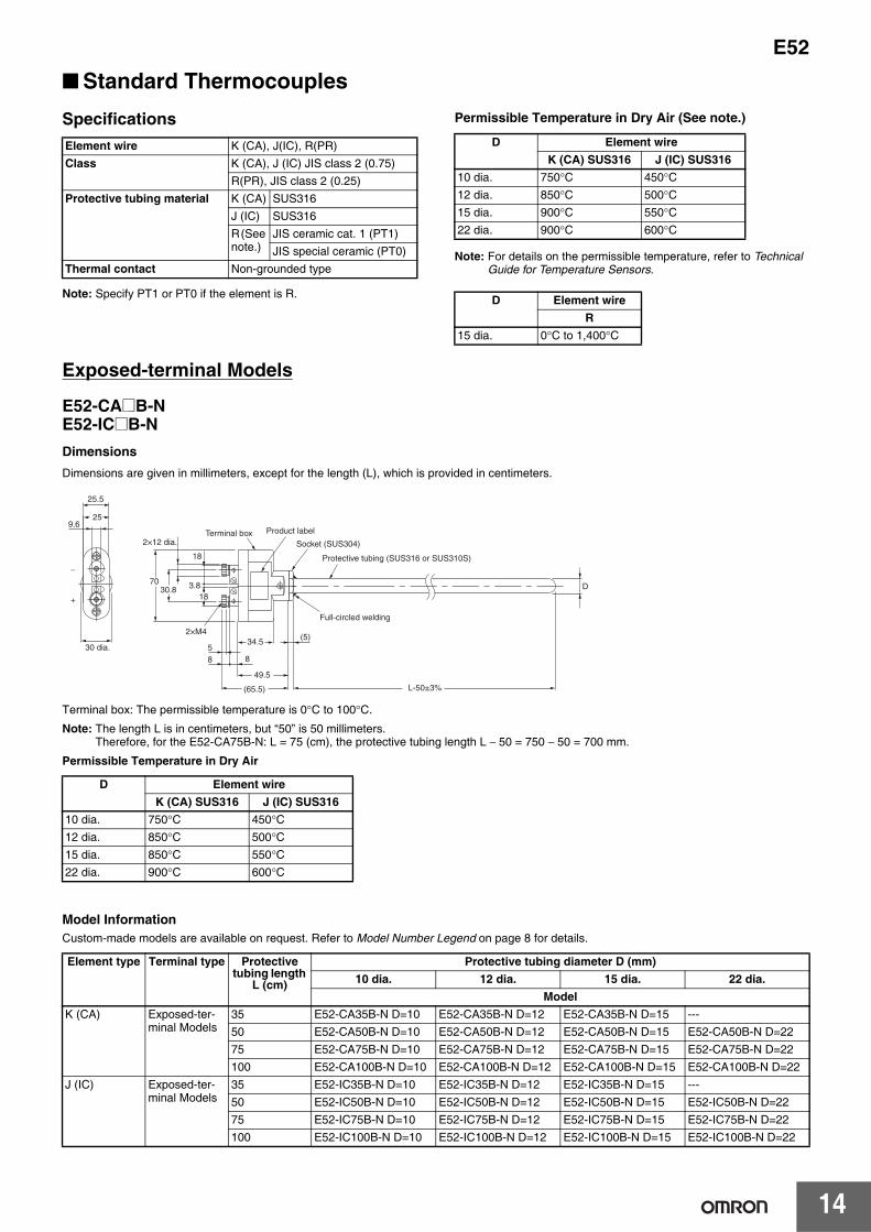
■ Standard ThermocouplesSpecifications
Note: Specify PT1 or PT0 if the element is R.
Permissible Temperature in Dry Air (See note.)
Note: For details on the permissible temperature, refer to Technical Guide for Temperature Sensors.
Exposed-terminal Models
E52-CA@B-NE52-IC@B-NDimensionsDimensions are given in millimeters, except for the length (L), which is provided in centimeters.
Terminal box: The permissible temperature is 0°C to 100°C.
Note: The length L is in centimeters, but “50” is 50 millimeters. Therefore, for the E52-CA75B-N: L = 75 (cm), the protective tubing length L − 50 = 750 − 50 = 700 mm.
Permissible Temperature in Dry Air
Model InformationCustom-made models are available on request. Refer to Model Number Legend on page 8 for details.
Element wire K (CA), J(IC), R(PR)Class K (CA), J (IC) JIS class 2 (0.75)
R(PR), JIS class 2 (0.25)Protective tubing material K (CA) SUS316
J (IC) SUS316R (See note.)
JIS ceramic cat. 1 (PT1)JIS special ceramic (PT0)
Thermal contact Non-grounded type
D Element wireK (CA) SUS316 J (IC) SUS316
10 dia. 750°C 450°C12 dia. 850°C 500°C15 dia. 900°C 550°C22 dia. 900°C 600°C
D Element wireR
15 dia. 0°C to 1,400°C
D Element wireK (CA) SUS316 J (IC) SUS316
10 dia. 750°C 450°C12 dia. 850°C 500°C15 dia. 850°C 550°C22 dia. 900°C 600°C
Element type Terminal type Protective tubing length
L (cm)
Protective tubing diameter D (mm)10 dia. 12 dia. 15 dia. 22 dia.
ModelK (CA) Exposed-ter-
minal Models35 E52-CA35B-N D=10 E52-CA35B-N D=12 E52-CA35B-N D=15 ---50 E52-CA50B-N D=10 E52-CA50B-N D=12 E52-CA50B-N D=15 E52-CA50B-N D=2275 E52-CA75B-N D=10 E52-CA75B-N D=12 E52-CA75B-N D=15 E52-CA75B-N D=22100 E52-CA100B-N D=10 E52-CA100B-N D=12 E52-CA100B-N D=15 E52-CA100B-N D=22
J (IC) Exposed-ter-minal Models
35 E52-IC35B-N D=10 E52-IC35B-N D=12 E52-IC35B-N D=15 ---50 E52-IC50B-N D=10 E52-IC50B-N D=12 E52-IC50B-N D=15 E52-IC50B-N D=2275 E52-IC75B-N D=10 E52-IC75B-N D=12 E52-IC75B-N D=15 E52-IC75B-N D=22100 E52-IC100B-N D=10 E52-IC100B-N D=12 E52-IC100B-N D=15 E52-IC100B-N D=22
88
30.870
49.5
(65.5)
25.5
25
18
3.818
534.5 (5)
D
9.6
2×M4
−
+
30 dia.
2×12 dia.
L-50±3%
Product label
Full-circled welding
Socket (SUS304)
Protective tubing (SUS316 or SUS310S)
Terminal box

15
E52Enclosed-terminal Models
E52-CA@C-NE52-IC@C-NDimensionsDimensions are given in millimeters, except for the length (L), which is provided in centimeters.
Note: The length L is in centimeters, but “50” is 50 millimeters. Therefore, for the E52-CA50C-N: L = 50 (cm), the protective tubing length L − 50 = 500 − 50 = 450 mm.
Permissible Temperature in Dry Air
Terminal box: The permissible temperature is 0°C to 90°C.
Note: The terminals in the cap indicate polarity (+ or −).
Model InformationCustom-made models are available on request. Refer to Model Number Legend on page 8 for details
D Element wireK (CA) SUS316 J (IC) SUS316
10 dia. 0 to 750°C 0 to 450°C12 dia. 0 to 850°C 0 to 500°C15 dia. 0 to 850°C 0 to 550°C22 dia. 0 to 900°C 0 to 600°C
Element type Terminal type Protective tubing length
L (cm)
Protective tubing diameter D (mm)10 dia. 12 dia. 15 dia. 22 dia.
ModelK (CA) Enclosed-ter-
minal Models35 E52-CA35C-N D=10 E52-CA35C-N D=12 E52-CA35C-N D=15 ---50 E52-CA50C-N D=10 E52-CA50C-N D=12 E52-CA50C-N D=15 E52-CA50C-N D=2275 E52-CA75C-N D=10 E52-CA75C-N D=12 E52-CA75C-N D=15 E52-CA75C-N D=22100 E52-CA100C-N D=10 E52-CA100C-N D=12 E52-CA100C-N D=15 E52-CA100C-N D=22
J (IC) Enclosed-ter-minal Models
35 E52-IC35C-N D=10 E52-IC35C-N D=12 E52-IC35C-N D=15 ---50 E52-IC50C-N D=10 E52-IC50C-N D=12 E52-IC50C-N D=15 E52-IC50C-N D=2275 E52-IC75C-N D=10 E52-IC75C-N D=12 E52-IC75C-N D=15 ---100 E52-IC100C-N D=10 E52-IC100C-N D=12 E52-IC100C-N D=15 ---
53
D
(5)
(86)
(92)
82 dia.
L-50±3%
38 dia.
Protective tubing (SUS316 or SUS310S)
Socket (SUS304)
Product label Full-circled Welding
Terminal box
(Packing internal diameter : 9 dia.)
Cap
Chain
12G

E52
16
Enclosed-terminal Models (High-temperature Use)
E52-PR@C-NDimensionsDimensions are given in millimeters, except for the length (L), which is provided in centimeters.
Note: The length L is in centimeters, but “150” is 150 millimeters. Therefore, for the E52-PR75C-N: L = 75 (cm), the protective tubing length L − 150 = 750 − 150 = 600 mm.
Model Information
Note: The permissible temperature given for the protective tubing is higher than 1,400°C, but the permissible temperature of the thermocouple element wire is only 1,400°C. Therefore, the protective tubing of the E52-PR@C-N can withstand high temperatures momentarily to the levels given in the table as exceptions, but the element wire will deteriorate quickly if the thermocouple is used regularly at temperatures that exceed the permissible temperature for the element wire.
Element type
Terminal type
Protective tubing
length L (cm)
Protective tubing diameter D (mm)
15 dia.Model
R (See note 1.)
Enclosed-ter-minal Models
50 E52-PR50C-N D=15 PT175 E52-PR75C-N D=15 PT1100 E52-PR100C-N D=15 PT1
R (See note 2.)
Enclosed-ter-minal Models
50 E52-PR50C-N D=15 PT075 E52-PR75C-N D=15 PT0100 E52-PR100C-N D=15 PT0
Standard Protective tubing material
Permissible temperature in dry
airNote 1:JIS ceramic Cat.1 (PT1)
Mullite, high alumina, etc.
1,500°C (See note.)
Note 2:JIS special ceramic (PT0)
Recrystallized alumina, fused alumina, etc.
1,600°C (See note.)
53
(5)
(100)
A
(86)
(92)
82 dia.
21.7 dia.38 dia.
L-150±3%
* Tubing distortionA dimensions more than 500mm: 0.6% or lessA dimensions are less than 500mm: 3mm or less
Support (SUS304)Ceramic protective tubing (PT0 or PT1)
Product label
Terminal box
Chain
Cap
(Packing internal diameter : 9 dia.)
12G
15±0.7 dia.
*
Use wiring terminals that fit M4 screws.
Permissible Temperature in Dry Air
Terminal box: The permissible temperature is 0°C to 90°C.
Note: The terminals in the cap indicate polarity (+ or −).
D Element wireR
15 dia. 0°C to 1,400°C

17
E52
Low-cost Models
■ Low-cost Platinum Resistance Thermometers
Exposed-lead Models with Screws
Exposed-lead Models with Flange
Exposed-lead Models
SpecificationsElement type Pt100Conductor type 3-conductor systemClass Class BProtective tubing material
SUS304
Sensor length 30 mmMax. detectable temperature
250°C
Temperature range
−50°C to 250°C
Lead wire Fluororesin-covered wire (PFA) with 1.0 outer dia.7/0.18−50°C to 150°C
E52-P6DYDimensions
Note: The protective tubing is of pipe construction, which must not be bent.
Lead wire length (m) Model1 E52-P6DY 1M2 E52-P6DY 2M4 E52-P6DY 4M
14(30)
15
(16)
(M-16)
M±5%
6±0.510±0.5
65 0-2
4±0.4 dia.
Protective tubing (SUS304)
Siliconized shrinkable tube
Product label
Lead wireMarking tube (Red)
Red
Crimping terminal Y type for M3.5
WhiteMarking tube (White)
Full-circled welding
Taper screw for tube R1/8 (SUS304)
Red (A)
Black (B)
Black (B)
SpecificationsElement wire Pt100Conductor type 3-conductor systemClass Class BProtective tubing material
SUS304
Sensor length 30 mmMax. detectable temperature
250°C
Temperature range
−50°C to 250°C
Lead wire Fluororesin-covered wire (PFA) with 1.0 outer dia.7/0.18−50°C to 150°C
E52-P6FYDimensions
Note: The protective tubing is of pipe construction, which must not be bent.
Lead wire length (m) Model1 E52-P6FY 1M2 E52-P6FY 2M4 E52-P6FY 4M
15
1
120°120°
30 dia.
20 dia.(30) (M-16)
3×3.5 dia.
65 0-2 M±5%
Flange (SUS304)
Nickel brazing
Marking tube (Red)
White
Product label
Lead wireProtective tubing (SUS304)
RedSiliconized shrinkable tube
Marking tube (White)
Crimping terminal Y type for M3.5
Red (A)
Black (B)
Black (B)
4±0.4 dia.
SpecificationsElement type Pt100Conductor type 3-conductor systemClass Class BProtective tubing material
SUS316
Max. detectable temperature
250°C
Temperature range
0°C to 250°C
Lead wire Fluororesin-covered wire (PFA) with 1.0 outer dia. 7/0.18−50°C to 150°C
E52-P10AEYDimensions
Note: 1. The protective tubing is of pipe construction, which must not be bent.2. A Compression Fitting (PT@) cannot be used for mounting.
Lead wire length (m) Model1 E52-P10AEY 1M2 E52-P10AEY 2M4 E52-P10AEY 4M
30 80±10
M±4%
30±5
100±3%
Product label
Shrinkable tube (Black)
Protective tubing (SUS316)
Crimping terminal Y type for M3.5
Siliconized shrinkable tubeTransparent
Marking tube (White)
Lead wire
Red (A)
White (B)
White (B)
3.2±0.05 dia.

E52
18
■ Low-cost Thermocouples
Exposed-lead Models with Spring
Note: The protective tubing is of pipe construction, which must not be bent.
Protective tubing length (mm) Lead wire length (m) Element type: K (CA) Element type: J (IC)Model
65 1 E52-CA6ASY 1M E52-IC6ASY 1M2 E52-CA6ASY 2M E52-IC6ASY 2M4 E52-CA6ASY 4M E52-IC6ASY 4M
100 1 E52-CA10ASY 1M E52-IC10ASY 1M2 E52-CA10ASY 2M E52-IC10ASY 2M4 E52-CA10ASY 4M E52-IC10ASY 4M
150 1 E52-CA15ASY 1M E52-IC15ASY 1M2 E52-CA15ASY 2M E52-IC15ASY 2M4 E52-CA15ASY 4M E52-IC15ASY 4M
200 1 E52-CA20ASY 1M E52-IC20ASY 1M2 E52-CA20ASY 2M E52-IC20ASY 2M4 E52-CA20ASY 4M E52-IC20ASY 4M
−
+
(20) (70)
100°
L±3 32±218±16.3±15±0.5
M±1% 80±10150±1
0+0.02
-0.1+0.2
Protective spring(SUS304)
Sleeve(Brass nickel chrome plating)
Protective tubing(SUS304)
Shrinkable tube(CA:Blue, IC:Yellow)
Marking tube (White)
Crimping terminal Y type for M3.5
Lead wireRed (+)
White (−)
8.2±0.1 dia.
12±0.05 dia.
1.2±0.02 dia.
4.8 dia.
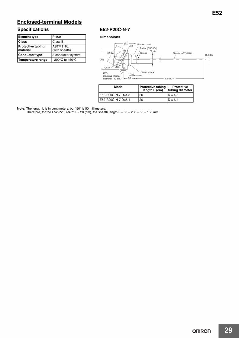
11±0.2 dia.
14.5 dia.
Specifications
Note: The sleeve resists temperatures ranging between 0°C and 100°C.
Element type K (CA), J (IC)Element dia. 0.65 mm (single wire)Class Class 2 (0.75)Protective tubing material
SUS304
Thermal contact Non-grounded typeTemperature range 0°C to 400°C: K (CA)
0°C to 350°C: J (IC)Lead wire Fully glass-wool-covered
compensating cable and external dimensions of approx. 5.1 x 3.04/0.650°C to 180°C
E52-CA@ASY, E52-IC@ASYDimensions
L: Protective tubing lengthM: Lead wire length
19
E52Exposed-lead Models with Screw
Protective tubing length (mm) Lead wire length (m) Element type: K (CA) Element type: J (IC)Model
M6 screw 1 E52-CA1DY M6 1M E52-IC1DY M6 1M2 E52-CA1DY M6 2M E52-IC1DY M6 2M4 E52-CA1DY M6 4M E52-IC1DY M6 4M
M8 screw 1 E52-CA1DY M8 1M E52-IC1DY M8 1M2 E52-CA1DY M8 2M E52-IC1DY M8 2M4 E52-CA1DY M8 4M E52-IC1DY M8 4M
W1/4 screw 1 E52-CA1DY W1/4 1M E52-IC1DY W1/4 1M2 E52-CA1DY W1/4 2M E52-IC1DY W1/4 2M4 E52-CA1DY W1/4 4M E52-IC1DY W1/4 4M
120°B
C
(70)(20)
80±10M±1%
A±0.3
3.8±1
9±1
1±0.1
3.8±0.1 dia.
5±0.05 dia.
10 -0.50
02.8 +0.3
Shrinkable tube(CA:Blue, IC:Yellow)
Lead wire
Screw(SUS304) Protective
copper wire
Sleeve(Brass nickel plated)
Blue
PVC less tube
Crimping terminal Y type for M3.5
Marking tube (White)
End ring (Brass)
Movable ring (Brass) Red
Black (−)
Red (+)
End Workpiece
Brass
0.65-dia. black wire
Movable ring
Cut after silver soldering
M6
Screw
Closely wound enamel-bonded coil.
Brass pipe
Shielded glass-wool lead wire
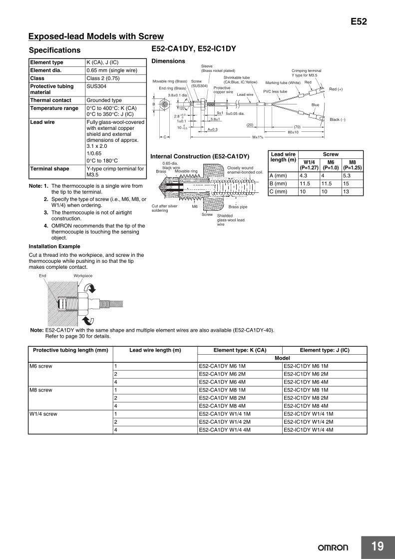
Specifications
Note: 1. The thermocouple is a single wire from the tip to the terminal.
2. Specify the type of screw (i.e., M6, M8, or W1/4) when ordering.
3. The thermocouple is not of airtight construction.
4. OMRON recommends that the tip of the thermocouple is touching the sensing object.
Installation ExampleCut a thread into the workpiece, and screw in the thermocouple while pushing in so that the tip makes complete contact.
Element type K (CA), J (IC)Element dia. 0.65 mm (single wire)Class Class 2 (0.75)Protective tubing material
SUS304
Thermal contact Grounded typeTemperature range 0°C to 400°C: K (CA)
0°C to 350°C: J (IC)Lead wire Fully glass-wool-covered
with external copper shield and external dimensions of approx. 3.1 x 2.01/0.650°C to 180°C
Terminal shape Y-type crimp terminal for M3.5
E52-CA1DY, E52-IC1DYDimensions
Lead wire length (m)
ScrewW1/4
(P=1.27)M6
(P=1.0)M8
(P=1.25)A (mm) 4.3 4 5.3B (mm) 11.5 11.5 15C (mm) 10 10 13
Note: E52-CA1DY with the same shape and multiple element wires are also available (E52-CA1DY-40).Refer to page 30 for details.
Internal Construction (E52-CA1DY)
E52
20
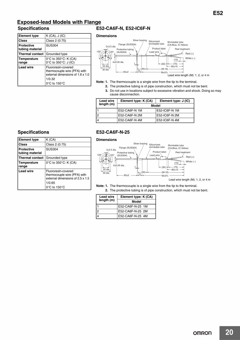
Exposed-lead Models with FlangeSpecificationsElement type K (CA), J (IC)Class Class 2 (0.75)Protective tubing material
SUS304
Thermal contact Grounded typeTemperature range
0°C to 350°C: K (CA)0°C to 350°C: J (IC)
Lead wire Fluororesin-covered thermocouple wire (PFA) with external dimensions of 1.6 x 1.0 1/0.320°C to 150°C
E52-CA6F-N, E52-IC6F-NDimensions
Note: 1. The thermocouple is a single wire from the tip to the terminal. 2. The protective tubing is of pipe construction, which must not be bent.3. Do not use in locations subject to excessive vibration and shock. Doing so may
cause disconnection.
Lead wire length (m)
Element type: K (CA) Element type: J (IC)Model
1 E52-CA6F-N 1M E52-IC6F-N 1M2 E52-CA6F-N 2M E52-IC6F-N 2M4 E52-CA6F-N 4M E52-IC6F-N 4M
15
1 (30)
(30)
120°
(75)
(10)
120°
(M-16)20 dia.
30 dia.
3×3.5 dia.
65±2 M±5%
80±10
Protective tubing (SUS304)
Flange (SUS304)
Silver brazing Siliconized shrinkable tube
Lead wire
Product label Peel treatment
Shrinkable tube(CA:Blue, IC:Yellow)
White (−)
Red (+)
4±0.05 dia.
Lead wire length (M): 1, 2, or 4 m
SpecificationsElement type K (CA)Class Class 2 (0.75)Protective tubing material
SUS304
Thermal contact Grounded typeTemperature range
0°C to 350°C: K (CA)
Lead wire Fluororesin-covered thermocouple wire (PFA) with external dimensions of 2.5 x 1.5 1/0.650°C to 150°C
E52-CA6F-N-25Dimensions
Note: 1. The thermocouple is a single wire from the tip to the terminal. 2. The protective tubing is of pipe construction, which must not be bent.
Lead wire length (m)
Element type: K (CA)Model
1 E52-CA6F-N-25 1M2 E52-CA6F-N-25 2M4 E52-CA6F-N-25 4M
15
1 (30)
(30)
120°
(75)
(10)
120°
(M-16)20 dia.
30 dia.
3×3.5 dia.
65±2 M±5%
80±10
Protective tubing (SUS304)
Flange (SUS304)
Silver brazing Siliconized shrinkable tube
Lead wire
Product label Peel treatment
Shrinkable tube(CA:Blue, IC:Yellow)
White (−)
Red (+)
4±0.05 dia.
Lead wire length (M): 1, 2, or 4 m

21
E52Exposed-lead Models with Screws
Exposed-lead Models
SpecificationsElement type K (CA), J (IC)Class Class 2 (0.75)Protective tubing material
SUS304
Thermal contact Grounded typeTemperature range
0°C to 350°C: K (CA)0°C to 350°C: J (IC)
Lead wire Fluororesin-covered thermocouple wire (PFA) with external dimensions of 1.6 x 1.0 1/0.30°C to 150°C
E52-CA6D-N, E52-IC6D-NDimensions
Note: 1. The thermocouple is a single wire from the tip to the terminal. 2. The protective tubing is of pipe construction, which must not be bent.3. Do not use in locations subject to excessive vibration and shock. Doing so may
cause disconnection.
Lead wire length (m)
Element type: K (CA) Element type: J (IC)Model
1 E52-CA6D-N 1M E52-IC6D-N 1M2 E52-CA6D-N 2M E52-IC6D-N 2M4 E52-CA6D-N 4M E52-IC6D-N 4M
(30)(M-16)
15
(30)(10)
14
(16)
(75)
65±2 M±5%
80±10
Full-circled welding
Protective tubing (SUS304)
Siliconized shrinkable tube
Lead wireProduct label Peel treatment
Shrinkable tube (CA:Blue, IC:Yellow)
Taper screw for tube R1/8 (SUS304)
White (−)
Red (+)
4±0.05 dia.
Lead wire length (M): 1, 2, or 4 m
SpecificationsElement type K (CA)Class Class 2 (0.75)Protective tubing material
SUS304
Thermal contact Grounded typeTemperature range
0°C to 350°C: K (CA)
Lead wire Fluororesin-covered thermocouple wire (PFA) with external dimensions of 2.5 x 1.5 1/0.650°C to 150°C
E52-CA6D-N-25Dimensions
Note: 1. The thermocouple is a single wire from the tip to the terminal. 2. The protective tubing is of pipe construction, which must not be bent.
Lead wire length (m)
Element type: K (CA)Model
1 E52-CA6D-N-25 D4.0 1M2 E52-CA6D-N-25 D4.0 2M4 E52-CA6D-N-25 D4.0 4M
(30)(M-16)
15
(30)(10)
14
(16)
(75)
65±2 M±5%
80±10
Full-circled welding
Protective tubing (SUS304)
Siliconized shrinkable tube
Lead wireProduct label Peel treatment
Shrinkable tube (CA:Blue, IC:Yellow)
Taper screw for tube R1/8 (SUS304)
White (−)
Red (+)
4±0.05 dia.
Lead wire length (M): 1, 2, or 4 m
SpecificationsElement type K (CA), J (IC)Class Class 2 (0.75)Protective tubing material
SUS304
Thermal contact Non-grounded typeTemperature range
0°C to 350°C: K (CA)0°C to 200°C: J (IC)
Lead wire Fluororesin-covered thermocouple wire (PFA) with external dimensions of 1.6 x 1.01/0.320°C to 180°C
E52-CA10AE-N, E52-IC10AE-NDimensions
Note: 1. The thermocouple is a single wire from the tip to the terminal.2. Lead wire length M: 1, 2, or 4 m3. The protective tubing is of pipe construction, which must not be bent.4. The thermocouple cannot be mounted using a PT@ Compression Fitting.
Lead wire length (m)
Element type: K (CA) Element type: J (IC)Model
1 E52-CA10AE-N 1M E52-IC10AE-N 1M2 E52-CA10AE-N 2M E52-IC10AE-N 2M4 E52-CA10AE-N 4M E52-IC10AE-N 4M
(10)(75)(30)
100±5 M±5%80±10
Protective tubing(SUS304)
Swage Lead wire
Product label
Shrinkable tube (CA:Blue, IC:Yellow)
Fluorocarbon resin protective tubingPeel treatment
White (−)
Red (+)3.2±0.05 dia.

E52
22
Exclusive Models
■ Thermocouples
Thermocouples for Molding Machines
Thermocouples with Crimp Terminal
15 20 (30)
10
1510
(80)85±10
25±2100±10
M±5%
15 dia.6.8 dia.
5 dia.
8 dia.12 dia.
Product label
Shrinkable tube(CA:Blue, IC:Yellow)
Red
White
White/Red Stripes (+)
CA: White/Blue Stripes (−)IC: White/Yellow Stripes (−)
Lead wire
Spring retainer(Brass nickel plated)
Spring
Bayonet(Brass nickel plated)
Protective tubing(SUS304)
Taper screw for tube R1/8 (Brass nickel plated)
Details of mounting bracket
Marking tube(White)
Marking tube (Red)
Crimping terminal Y type for M3.5
4.8±0.05 dia.
SpecificationsElement type K (CA), J (IC)Element diameter
1.0 mm (single wire)
Class Class 2 (0.75)Protective tubing material
SUS304
Thermal contact Grounded typeTemperature range
0°C to 350°C
Lead wire Glass-covered stainless steel shielded thermocouple wire with 4 dia.1/1.00°C to 180°C
E52-CA2GVY, E52-IC2GVYDimensions
Lead wire length (m)
Element type: K (CA) Element type: J (IC)Model
1 E52-CA2GVY 1M E52-IC2GVY 1M2 E52-CA2GVY 2M E52-IC2GVY 2M
Note: The Adapter is included with the Thermocouple.If it is lost or damaged, you can order a replacement with the following model number.Adapter: Y92F-S1
Lead wire length (M): 1 or 2 m
Specifications
Note: The E52-CA1GTY is also available with double elements. Refer to page 30 for details.
Element type K (CA), J (IC)Element diameter
0.65 mm (single wire)
Class Class 2 (0.75)Thermal contact Grounded typeTemperature range
0°C to 300°C
Lead wire Glass-covered stainless steel shielded thermocouple wire with 4 dia.1/1.00°C to 150°C
Terminal shape Y-type crimp terminal for M3.5
E52-CA1GTY, E52-IC1GTYDimensions
Lead wire length (m)
Element type: K (CA) Element type: J (IC)Model
1 E52-CA1GTY 1M E52-IC1GTY 1M2 E52-CA1GTY 2M E52-IC1GTY 2M
(80)
8
White (−)15±5
Max. 6 dia.4.3 dia.
30±5
M±4%90±10
Crimping terminal Y type for M3.5
Crimping terminal round type for M4 (N1.25-4)
Siliconized shrinkable tube
Lead wire
Shrinkable tube(CA:Blue, IC:Yellow)
Transparent vinyl tube
Marking tube (White)
Transparent
White/Red Stripes (+)
Temperature measuring junction
Product label
Lead wire length (M): 1 or 2 m

23
E52
■ Platinum Resistance Thermometers
Platinum Resistance Thermometers for Surface Temperature Measurement
Platinum Resistance Thermometers for Room Temperature Measurement
Waterproof Platinum Resistance Thermometers
SpecificationsElement type Pt100Class Class BProtective tubing material
SUS304With brass-nickel-plated bracket
Conductor type 3-conductor systemTemperature range
−50°C to 250°C
Lead wire Silicone-covered 3-conductor cable and approx. 3.9 dia.30/0.08−50°C to 150°C
E52-P2GSYDimensions
Lead wire length (m) Model1 E52-P2GSY 1M2 E52-P2GSY 2M
(30)
(50) (80)
5
3
1.5
6
4.5
20±0.5
28±1
30±5
90±10M±4%
20±1
14±0.5
4×3.2 dia.(7.5 dia.)
Crimping terminal Y type for M3.5
Shrinkable tube (Black)
Siliconized shrinkable tube
Blacket(Brass nickel plated)
Transparent
Lead wire
Marking tube (White)
Product label Red (A)
White (B)
White (B)
Lead wire length (M): 1 or 2 m
(95)
(30)
60
85
(80)85±10
M±5%97±1100±4
4.5±14.8 dia.
8 dia.
56±1
69.5±1
42±1
2×8 dia.
70±1
RedShrinkable tube (Black)
Lead wire
Protective tubing (SUS304)
Protective piping(Brass nickel plated)
Terminal box
Chain
Product label
Crimping terminal Y type for M3.5
Marking tube (Red)
Marking tube (White)White
Red (A)
White (B)
Black (B)
22.2±1 dia.
SpecificationsElement type Pt100Class Class BProtective tubing material
SUS304
Conductor type 3-conductor systemTemperature range
−50°C to 60°C
Lead wire Vinyl-covered 3-conductor cable with 6.1 dia.20/0.18−25°C to 60°C
E52-P10GRYDimensions
Lead wire length (m) Model2 E52-P10GRY 2M
SpecificationsElement wire Pt100Class Class BProtective tubing material
SUS304
Conductor type 3-conductor systemTemperature range 0°C to 70°C (underwater)
−20°C to 70°C (in the air)Lead wire Vinyl-covered 3-conductor
cable with 6.1 dia.12/0.18−25°C to 60°C
Resistive pressure 981 kps
E52-P10GPYDimensions
Note: The lead wires are vinyl-covered, and cannot be used underwater. Use the E52-P5AY-40 if waterproof lead wires are required for use underwater. Refer to page 25 for details.
Lead wire length (m) Model2 E52-P10GPY 2M4 E52-P10GPY 4M
(80)12
62 5
(30)
100±2 M±5%85±10
20 dia.
Red
WhiteMarking tube (White)
Full-circled Welding
Sleeve (SUS304)
Lead wireProduct label
Shrinkable tube (Black) Crimping terminal Y type for M3.5
Marking tube (Red)Protective tubing (SUS304)
Red (A)
White (B)
Black (B)7±0.2 dia.
Lead wire length (M): 1 or 2 m

E52
24
Corrosion-resistant Models with Fluororesin-covered Protective Tubing
■ Thermocouples
Exposed-lead Models
■ Platinum Measurement
Exposed-lead Models
22 8
55(80)
d
(L-5)
D±0.1
Ds±0.05
L 0+4
5 -5+9
M±4%
30±5
90±10
Shrinkable tube(CA:Blue, IC:Yellow)
Crimping terminal Y type for M3.5
Marking tube (White)
Product label
Lead wire
Sleeve (SUS304)
Fixed with adhesive tape and siliconized shrinkable tube
FEP-covered tubing
Transparent
Sheath (ASTM316L)
White (−)Red (+)
E52-CA20AY-1Dimensions
Model Protective tubing
length L (cm)
Protective tubing
diameter
Sleeve diameter
(mm)Sleeve
length (mm)
tube thickness
(mm)
Lead wire
length (m)
E52-CA20AY-1 D=4.6 2M 20 D = 4.6 d = 8l = 55
0.7 0.5E52-CA20AY-1 D=6 2M D = 6.0 0.6E52-CA20AY-1 D=8 2M D = 8.0 d = 11
l = 550.8
SpecificationsElement type K (CA)Class Class 2 (0.75)Protective tubing material
ASTM316L with Fluororesin-covered (FEP) tube
Thermal contact Non-grounded typeTemperature range 0°C to 180°CLead wire Vinyl-covered: −20°C
to 70°C
(30)35
A
(10)
(20)(10)
(80)85±10M±4%L+5 ±3%
D±0.1
Ds±0.05 8 dia.
Fixed with adhesive tape and siliconized shrinkable tube
Sheath (SUS316)
FEP-covered tubing
Sleeve (SUS304)Product label
Shrinkable tube (Black)
Lead wire
Crimping terminal Y type for M3.5Tube nose shape : Round Marking tube
(Red)
Marking tube (White)
Red
White
Red (A)
White (B)
Black (B)
E52-P20AY-1Dimensions
Model Protective tubing
length L (cm)
Protective tubing
diameter
Sleeve diameter
(mm)
Coating thickness
(mm)
Lead wire length (m)
E52-P20AY-1 D=4.6 2M 20 D = 4.6 d = 8 0.7 2E52-P20AY-1 D=6 2M D = 6.0 d = 8 0.6E52-P20AY-1 D=8 2M D = 8.0 d = 8 0.8
SpecificationsElement type Pt100Class Class BProtective tubing material
SUS316 with Fluororesin-covered (FEP) tube
Conductor type 3-conductor systemTemperature range −80°C to 180°CLead wire Vinyl-covered: −20°C
to 70°C

25
E52FEP-molded Models (Completely Waterproof)
(80)
90±1030±5
M±4%
65 -1+4
6 dia.-0.5+0.1 FEP tube
Fusion(Completely waterproof)
Lead wireProduct label
Shrinkable tube (Black)
Crimping terminal Y type for M3.5
Marking tube (White)
Transparent
Red (A)
White (B)
White (B)
E52-P5AY-40Dimensions
Model Lead wire length (m)E52-P5AY-40 2M 2E52-P5AY-40 4M 4E52-P5AY-40 6M 6E52-P5AY-40 8M 8
SpecificationsElement type Pt100Class Class BProtective tubing material
Fluororesin (FEP) tube (element / fluororesin mold (FEP))
Conductor type 3-conductor systemTemperature range −50°C to 180°CLead wire Fluororesin (FEP)
cover (with outer cover): −50°C to 180°C

E52
26
Pressure-resistant Explosion-proof (IICT6) Models
■ ThermocouplesEnclosed-terminal Models
70
L1=50
L
(64.5)
(113)
(10)
(131.5)
110
15 dia.
L2±3%
6.4±0.05 dia.
Cap
Official approval success label
Chain
Support (SUS304)
Socket (SUS304)
Full-circled Welding
Sheath (ASTM316L)
Pressure-resistant explosion-proofcable ground
(Adopted cable diameter: for 9-10 dia.)
Back: Product label
Terminal box
Explosion-proof display label
SpecificationsElement type K (CA)Class Class 2 (0.75)
Class 3 (Level 1.5) at -40°C and under
Protective tubing material L2 section: ASTM316LL1 section: SUS304
Explosion-proof specifica-tions
Construction Pressure-resistant explosion-proof structure
Explosion-protected class and ignitability
IICT6
Explosion-proof temperature range
−20°C to 85°C
Lead wire wiring method
Pressure-resistant packing cable ground type
Conduit thread G1/2Installation method Conforms to Technical
Recommendations of the Research Institute of Industrial Safety (Japan)
Model Protective tubing length
L (cm)
Protective tubing
diameter
L2 (mm)
E52-CA20C-N-6 D=6.4 L2=150 20 D = 6.4 150E52-CA35C-N-6 D=6.4 L2=300 35 D = 6.4 300E52-CA50C-N-6 D=6.4 L2=450 50 D = 6.4 450E52-CA75C-N-6 D=6.4 L2=700 75 D = 6.4 700
E52-CA@@C-N-6Dimensions

27
E52
■ Platinum Resistance Thermometers for Surface Temperature MeasurementEnclosed-terminal Models
Model Protective tubing length
L (cm)
Protective tubing
diameter
L2 (mm)
E52-P20C-N-6 D=6.4 L2=150 20 D = 6.4 150E52-P35C-N-6 D=6.4 L2=300 35 D = 6.4 300E52-P50C-N-6 D=6.4 L2=450 50 D = 6.4 450E52-P75C-N-6 D=6.4 L2=700 75 D = 6.4 700
70
L1=50
L
(64.5)
(113)
(10)
(131.5)
110L2±3%
6.4±0.05 dia.
15 dia.
Official approval success label
Support (SUS304)
Socket (SUS304)
Full-circled Welding
Sheath (ASTM316L)
Pressure-resistant explosion-proofcable ground(Adopted cable diameter: for 9-10 dia.)
Explosion-proof display labelBack: Product label
Terminal boxCap
Chain
SpecificationsElement type Pt100Class Class BProtective tubing material L2 section: ASTM316L
L1 section: SUS304Explosion-proof specifica-tions
Construction Pressure-resistant explosion-proof structure
Explosion-protected class and ignitability
IICT6
Explosion-proof temperature range
−20°C to 85°C
Lead wire wiring method
Pressure-resistant packing cable ground type
Conduit thread G1/2Installation method Conforms to Technical
Recommendations of the Research Institute of Industrial Safety (Japan)
E52-P@@C-N-6Dimensions

E52
28
Double-element Models
■ Thermocouple
Exposed-lead Models
■ Platinum Resistance Thermometers
Exposed-lead Models
E52-CA20AY-7Dimensions
SpecificationsElement type K (CA)Class Class 2 (0.75)Protective tubing material
ASTM316L (with sheath)
Thermal contact Non-grounded typeTemperature range
0°C to permissible temperature limit
Lead wire Vinyl-covered with external dimensions of 2.4 x 4.17/0.3−20°C to 70°C
(80)
55L±3%
30±5
M±4%90±10
11 dia.D±0.05Lead wire
Product labelSleeve (SUS304)
Sheath (ASTM316L) Swage
Crimping terminal Y type for M3.5
Transparent
Marking tube (White)
Shrinkable tube (Blue)
White (−)Red (+)
White (−)Red (+)
Permissible Temperature in Dry Air
D Element wireK (CA)
ASTM316L3.2 dia. 750°C4.8 dia. 800°C6.4 dia. 800°C8.0 dia. 900°C
Model Protective tubing length L
(cm)
Protective tubing
diameter
Sleeve diameter
(mm)
Permissible Temperature
(°C)
Lead wire length (m)
E52-CA20AY-7 D=3.2 2M 20 D = 3.2 d = 11 750 2E52-CA20AY-7 D=4.8 2M D = 4.8 d = 11 800 2E52-CA20AY-7 D=6.4 2M D = 6.4 d = 11 800 2E52-CA20AY-7 D=8.0 2M D = 8.0 d = 11 900 2
(80)
55
1
2
90±10M±4%L±3%
30±5
11 dia.D±0.05
SwageSheath (ASTM316L) Product label
Shrinkable tube (Black)
Wire mark (1,2) (White)
Sleeve (SUS304)
Crimping terminal Y type for M3.5
Transparent
Marking tube (White)Lead wire
Contradistinctive view
Red (A)
Red (A)
White (B)
White (B)
White/Black Stripes (B)
White/Black Stripes (B)
E52-P20AY-7Dimensions
SpecificationsElement type Pt100Class Class BProtective tubing material
ASTM316L(with sheath)
Conductor type 3-conductor systemTemperature range
−200°C to 450°C
Lead wire Vinyl-covered with 6.5 dia.19/0.18 −20°C to 70°C
Model Protective tubing length L (cm)
Protective tubing diameter
Lead wire length (m)
E52-P20AY-7 D=4.8 2M 20 D = 4.8 2E52-P20AY-7 D=6.4 2M D = 6.4 2
29
E52Enclosed-terminal Models
Note: The length L is in centimeters, but “50” is 50 millimeters. Therefore, for the E52-P20C-N-7: L = 20 (cm), the sheath length L − 50 = 200 − 50 = 150 mm.
53
(15)
L-50±3%
82 dia.38 dia.
(92)
(86)
D±0.05
Chain
Cap
G3/4(Packing internal diameter : 12 dia.)
Socket (SUS304)
Product label
Swage
Terminal box
Sheath (ASTM316L)
E52-P20C-N-7Dimensions
SpecificationsElement type Pt100Class Class BProtective tubing material
ASTM316L(with sheath)
Conductor type 3-conductor systemTemperature range −200°C to 450°C
Model Protective tubing length L (cm)
Protective tubing diameter
E52-P20C-N-7 D=4.8 20 D = 4.8E52-P20C-N-7 D=6.4 20 D = 6.4

E52
30
Silicone-covered Lead Wires Models
■ Thermocouples Exposed-lead Models with ScrewsSpecifications
Note: Refer to the installation example for the E52-CA1DY.
E52-CA1DY-40Dimensions
Thermocouples with Crimp TerminalSpecifications
E52-CA1GTY-14Dimensions
Element type K (CA)Class Class 2 (0.75)Screw material SUS304Thermal contact Grounded typeTemperature range 0°C to 300°CLead wire Silicone-covered with external dimensions of 3.5 x 4.9
30/0.1 0°C to 150°C
Terminal shape Y-type crimp terminal for M3.5
Model Screw pitch Lead wire length (m)
E52-CA1DY-40 M6 1M M6 (P=1.0) 1E52-CA1DY-40 M6 2M M6 (P=1.0) 2E52-CA1DY-40 M6 4M M6 (P=1.0) 4
Element type K (CA)Class Class 2 (0.75)Thermal contact Grounded typeTemperature range 0°C to 200°CLead wire Silicone-covered compensating cable with external dimensions of 3.2 x 4.6
30/0.10°C to 150°C
Terminal shape Y-type crimp terminal for M3.5
8±0.05 dia.
06.5 dia.+0.050.6 dia.
(20)
120°
3.8±0.1 dia.
B
C
(70)80±10
M±1%
A±0.3
13±1
80±51±0.1
10 -0.50
02.8 +0.3
Lead wire
Blue
Marking tube (White)
Crimping terminal Y type for M3.5Movable ring (Brass)
Screw (SUS304)
Sleeve (Brass nickel plated)
Shrinkable tube (Blue)
Protective spring (SUS304) RedEnd ring (Brass)
White (−)
Red (+)
6.6
4.3 dia.
Max. 7 dia.
15±5 30±5 (80)
90±10
M±4%
Lead wire
Siliconized shrinkable tube
Shrinkable tube (CA:Blue, IC:Yellow)
Crimping terminal Y type for M3.5
Product label
TransparentMarking tube (White)
Crimping terminal round type for M4 (N1.25-4)
White (−)
Red (+)
Lead wire length (M): 1 or 2 m
Model Lead wire length (m)E52-CA1GTY-14 1M 1E52-CA1GTY-14 2M 2

31
E52
Special models for Packaging Machines
■ Model Number LegendThe type of protective tubing length, and lead length can be specified as shown below.
Example:Element: K, protective tubing length: 12 cm, exposed leads, Y-type crimp terminals for M3.0, protective tubing diameter: 1 mm, flexible and heat resistive, lead length: 2 m
E52-CA12AY D=1 S2 2M
E 52 - C A � A Y D = 1 S � � M
Code Element typeCA K
Diameter (D) Length (L)1.0 61.0 12
1.0 3 to 100 (in centimeters, variable)
Code Terminal typeA Exposed lead wires
Code Terminal processingY Y-type crimp terminals for M3.0
Code
Lead wire length M (m)Specify the M length in meters.Range: 0.5, 1, 2, or 0.5 to 12 (in meters, variable)
Protective tubing length L (cm)Specify the length in centimeters within the following range: Unit (cm)
Protective tubing diameter (D)D=1 1 mm
Protective tubing structureSheathed
Code ApplicationS Temperature sensors for packaging machines
Code Compensating conductor
2 Flexible and heat resistant (30 cores)
1 Heat resistant (7 cores)

E52
32
Sheathed ThermocouplesSpecifications
Note: Usage together with the automatic filter adjustment function of E5@D Digital Temperature Controllers is recommended.
Exposed-lead ModelsE52-CA@AYDimensions
*1. Lead wires (compensating conductor) (excluding Y-type crimp terminals)Heat-resistance model (0 to 200°C): PFA glass-wool sheath with stainless outer shieldFlexible, heat-resistance model (0 to 200°C): PFA glass-wool sheath with stainless outer shield
*2. Temperature range of sleeve: 0 to 260°C*3. The sheath can be easily bent. Performance will not be adversely affected even if the sheath is bent somewhat.
Do not bend the sheath beyond the following value.Minimum bending radius: 2 mmBendable section: 8 mm or farther from the end
List of ModelsCustom-made models are available on request. Refer to page 31 for details.
Element type K (CA)Class Class 2 (0.75)Thermal contact Grounded typeTemperature range 0°C to 650°C
Terminal type
Protective tubing diameter D (mm)
Protective tubing length L (cm)
Lead wire type
Lead wire length M (m)0.5 1 2
Model
Exposed-lead Models 1 dia.
6Heat resistive E52-CA6AY D=1 S1 0.5M E52-CA6AY D=1 S1 1M ---
FlexibleHeat resistive --- E52-CA6AY D=1 S2 1M E52-CA6AY D=1 S2 2M
12Heat resistive E52-CA12AY D=1 S1 0.5M E52-CA12AY D=1 S1 1M ---
FlexibleHeat resistive --- E52-CA12AY D=1 S2 1M E52-CA12AY D=1 S2 2M
1 ±0.05 dia.
Shrinkable tube (blue)
Lead wire *1
Sheath (ASTM316L) *3
Sleeve (PPS resin) *2 Product label
90±10
(80)30±5
L±3% M±4%
S1: 5.5 dia.
S2: 6.4 dia. S1: 2.8 dia.S2: 3.6 dia.
Red: +
White: −
30
Y-type crimp terminals for M3.0
Mark tube (white)
+0.1−0.3
+0.1−0.3

33
E52Installation MethodA Temperature Sensor for Packing Machines has a diameter of 1.0 mm.To measure the temperature close to the seal surface, mount the Sensor as close as possible to the surface.
The following installation methods are assumed.
Use the following brackets or the equivalent to mount a Temperature Sensor for Packaging Machines to a hot plate.
Note: All of the above mounting brackets are SUS304.
Mounting bracket Application Manufacturer Model number
(1) 1-mm-dia. protective tube bracket Misumi Corporation Square ShimsASFCS-series
(2)
Sleeve bracket (S1)Misumi Corporation Cable Clips
COPU3-20P
Digi-Key Cable ClampRPC1156-ND
Sleeve bracket (S2)Misumi Corporation Cable Clips
COPU4-20P
Digi-Key Cable ClampRPC1474-ND
To correctly measure the surface temperature, the following installation conditions are recommended.
Enlargement Bend to a radius of 2 mm or larger.
Insert the end by 8 mm or longer.
Approx. 1 to 3.5 mm
Heater
Example 2: Groove for Temperature Sensor created in heating plate and Temperature Sensor secured with a cover.
Example 3: Lateral hole for the Temperature Sensor created in the heating plate and the Temperature Sensor inserted into it.
Example 1: Groove for Temperature Sensor created in heating plate and Temperature Sensor secured with mounting brackets.
There is a temperature sensing element at the tip of the Sensor. Always press the tip against the heating plate.
Always insert the Temperature Sensor all the way to the surface of the packing material.
(2)
(1)

E52
34
Thermistors
Element Interchangeable Thermistor for E5CS and E5C2
Temperature Ranges
Specifications
Error
Permissible Temperature
Note: Models with non-standard lead wire length and protective tubing length are available on request.
This Thermistor is a dedicated Thermistor for the E5C2 and E5CS.
Temperature range
Color code Nominal resistance Thermistor constant
Lead wire
−50°C to 50°C Blue 6 kΩ (0°C) 3390K A pair of 0.12 dia. 7 Fluororesin-insulated stranded wires with 0.86 outer dia. each0°C to 100°C Black 6 kΩ (0°C) 3390K
50°C to 150°C Red 30 kΩ (0°C) 3450K100°C to 200°C Yellow 0.55 kΩ (200°C) 4300K150°C to 300°C Green 4 kΩ (200°C) 5133K Flat glass-wool-shielded lead cable with 0.12 dia. 10 conductors
and external dimensions of 2.5 × 1.55
Item E52-THE@@Coupling method Element interchangeable thermistorClass JIS class 1Protective tubing material SUS304Time constant 8 to 15 s in still waterDissipation factor 2.4 to 2.8 mW/°C in still airLead wire heat resistive temperature
180°C
Detectable temperature Error−50°C to 100°C ±1°C max.100°C to 350°C ±1% max. of detectable temperature
Detectable temperature Operating temperature−50°C to 50°C 100°C0°C to 100°C 150°C50°C to 150°C 200°C100°C to 200°C 250°C150°C to 300°C 350°C

E52
35
Exposed-lead Models
E52-THE5ADimensions
Note: The lead wires have no polarity
Exposed-lead Models with Screws
E52-THE6DDimensions
Note: The lead wires have no polarity
Exposed-lead Models with Flange
E52-THE6FDimensions
Note: The lead wires have no polarity
Note: 1. The Thermistor lead cable can be extended with a standard lead wire for extension.2. Be sure to specify the model and temperature range when ordering the Thermistor. The Thermistor has a color code according to the
temperature range.
(50) (10)(5) (4)
4±0.08 dia.
50±1 M±5%
(15)
Protective tubing(SUS304)
Swage Lead wireProtective tube Peel treatment
Marking tube
TransparentTemperature range Model
−50°C to 50°C E52-THE5A −50-50°C 1M0°C to 100°C E52-THE5A 0-100°C 1M50°C to 150°C E52-THE5A 50-150°C 1M100°C to 200°C E52-THE5A 100-200°C 1M150°C to 300°C E52-THE5A 150-300°C 1M
610
65±1
(5) (4)
M±5%
(10)(15)(15)
(50)14
(16)
4±0.08 dia.
Protective tubing (SUS304)
Lead wire
Protective tube Peel treatment
Marking tube
TransparentSwage
Tapered screw for tube R1/8(SUS304)
Temperature range Model−50°C to 50°C E52-THE6D −50-50°C 1M0°C to 100°C E52-THE6D 0-100°C 1M50°C to 150°C E52-THE6D 50-150°C 1M100°C to 200°C E52-THE6D 100-200°C 1M150°C to 300°C E52-THE6D 150-300°C 1M
120°120°
20 dia.
30 dia.
3×3.5 dia.
4±0.08 dia.
65±1 M±5%
(10)(50)
(5)
(1)
(4)
(15)
(15)
Protective tubing(SUS304) Lead wire
Protective tube
Peel treatment
Marking tubeSilver brazing
TransparentFlange (SUS304)
Swage
Temperature range Model−50°C to 50°C E52-THE6F −50-50°C 1M0°C to 100°C E52-THE6F 0-100°C 1M50°C to 150°C E52-THE6F 50-150°C 1M100°C to 200°C E52-THE6F 100-200°C 1M150°C to 300°C E52-THE6F 150-300°C 1M

36
E52 (Ferrule)
General-purpose Models (with Ferrule)
■ Model Number LegendThe type of resistance thermometer, protective tubing length, and lead length can be specified as shown below.
Platinum Resistance Thermometers1. Element type
P: Pt1002. Protective tubing length (L)
Specify the length in centimeters within the following range: Unit (cm)E52-P@AF
3. TerminalAF: Exposed lead wires (with Ferrule)
4. Diameter3.2: 3.2-mm dia. (Protective tubing construction: Sheathed)
E52-@@AF only4.8: 4.8-mm dia. (Protective tubing construction: Sheathed)
E52-@@AF only6.4: 6.4-mm dia. (Protective tubing construction: Sheathed)
E52-@@AF only5. Heat resistance
Specify for E52-P@AF model only.6. Lead length (M)
Specify the length in meters within the following range for the E52-@@AF only:Range: 0.5, 1 to 100 m
ExamplesElement: Pt100, protective tubing length: 420 mm, exposed leads, protective tubing dia.: 4.8 mm, heat resistive, lead length: 10 m
E52-P42AF D=4.8 NETU 10M
■ Sheathed Platinum Resistance ThermometersRefer to Model Number Legend above for the Pt100.
Specifications
Diameter (D) Length (L)3.2 7 to 1004.8 10 to 6006.4 13 to 1,300
Code Temperature range Lead type--- −20°C to 70°C
Sleeve: 0°C to 70°CVinyl-covered
NETU 0°C to 180°CSleeve: 0°C to 100°C
Glass-wool-covered, externally shielded with stainless
Element type Pt100Class JIS class BSheath material SUS316 (E52-P@AF)
ASTM316L (E52-P@B-N, E52-P@C-N)Sheath outer diameter 3.2 dia., 4.8 dia., 6.4 dia., 8 diaConductor type 3-conductor systemTemperature range −196°C to 450°C (in dry air)
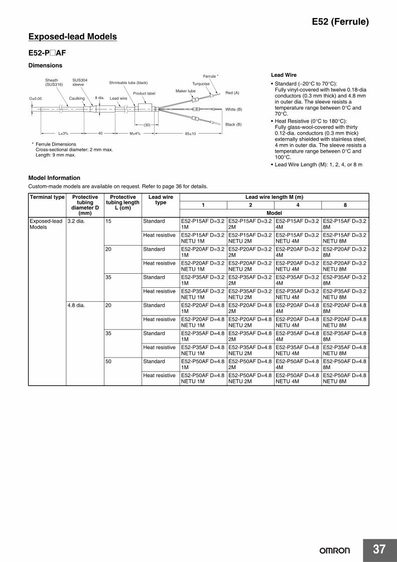
37
E52 (Ferrule)Exposed-lead Models
E52-P@AFDimensions
Model InformationCustom-made models are available on request. Refer to page 36 for details.
Terminal type Protective tubing
diameter D (mm)
Protective tubing length
L (cm)
Lead wire type
Lead wire length M (m)1 2 4 8
ModelExposed-lead Models
3.2 dia. 15 Standard E52-P15AF D=3.2 1M
E52-P15AF D=3.2 2M
E52-P15AF D=3.2 4M
E52-P15AF D=3.2 8M
Heat resistive E52-P15AF D=3.2 NETU 1M
E52-P15AF D=3.2 NETU 2M
E52-P15AF D=3.2 NETU 4M
E52-P15AF D=3.2 NETU 8M
20 Standard E52-P20AF D=3.2 1M
E52-P20AF D=3.2 2M
E52-P20AF D=3.2 4M
E52-P20AF D=3.2 8M
Heat resistive E52-P20AF D=3.2 NETU 1M
E52-P20AF D=3.2 NETU 2M
E52-P20AF D=3.2 NETU 4M
E52-P20AF D=3.2 NETU 8M
35 Standard E52-P35AF D=3.2 1M
E52-P35AF D=3.2 2M
E52-P35AF D=3.2 4M
E52-P35AF D=3.2 8M
Heat resistive E52-P35AF D=3.2 NETU 1M
E52-P35AF D=3.2 NETU 2M
E52-P35AF D=3.2 NETU 4M
E52-P35AF D=3.2 NETU 8M
4.8 dia. 20 Standard E52-P20AF D=4.8 1M
E52-P20AF D=4.8 2M
E52-P20AF D=4.8 4M
E52-P20AF D=4.8 8M
Heat resistive E52-P20AF D=4.8 NETU 1M
E52-P20AF D=4.8 NETU 2M
E52-P20AF D=4.8 NETU 4M
E52-P20AF D=4.8 NETU 8M
35 Standard E52-P35AF D=4.8 1M
E52-P35AF D=4.8 2M
E52-P35AF D=4.8 4M
E52-P35AF D=4.8 8M
Heat resistive E52-P35AF D=4.8 NETU 1M
E52-P35AF D=4.8 NETU 2M
E52-P35AF D=4.8 NETU 4M
E52-P35AF D=4.8 NETU 8M
50 Standard E52-P50AF D=4.8 1M
E52-P50AF D=4.8 2M
E52-P50AF D=4.8 4M
E52-P50AF D=4.8 8M
Heat resistive E52-P50AF D=4.8 NETU 1M
E52-P50AF D=4.8 NETU 2M
E52-P50AF D=4.8 NETU 4M
E52-P50AF D=4.8 NETU 8M
B
A
B
SUS304 sleeve
Sheath (SUS316)
Lead wireCaulkingD±0.05
L±3%
Product label Red (A)
White (B)
Black (B)
Ferrule *
Maker tube
Turquoise
M±4% 85±10
Shrinkable tube (black)
(30)
40
8 dia.
Lead Wire• Standard (−20°C to 70°C):
Fully vinyl-covered with twelve 0.18-dia conductors (0.3 mm thick) and 4.8 mm in outer dia. The sleeve resists a temperature range between 0°C and 70°C.
• Heat Resistive (0°C to 180°C):Fully glass-wool-covered with thirty 0.12-dia. conductors (0.3 mm thick) externally shielded with stainless steel, 4 mm in outer dia. The sleeve resists a temperature range between 0°C and 100°C.
• Lead Wire Length (M): 1, 2, 4, or 8 m
* Ferrule DimensionsCross-sectional diameter: 2 mm max.Length: 9 mm max.

E52 (Ferrule)
38
■ Model Number LegendThe type of resistance thermometer, protective tubing length, and lead length can be specified as shown below.
Thermocouples1. Element type
CA:K2. Protective tubing length (L)
Specify the length in centimeters in the following range: Unit (cm)
E52-CA@AF (Exposed-lead Model)
3. TerminalAF: Exposed lead wires (with Ferrule) (element type: K, J)
4. DiameterSpecify the protective tubing material according to the table.
5. Heat resistanceSpecify this item for the exposed-lead models only.
6. Lead length (M)Specify the length in meters in the following range for the E52-CA@AF only.Range: 1 to 100 m
7. Protective tubing material
ExamplesElement: K; protective tubing length: 420 mm, exposed leads, protective tubing dia.: 4.8 mm, heat resistive, lead length: 10 m
E52-CA@AF D=4.8 NETU 10M
Diameter (D) Length (L)1 2 to 2001.6 3 to 5003.2 5 to 2,0004.8 8 to 2,3006.4 10 to 1,2008 12 to 1,000
Code Diameter (D)
Protective tubing construction
Protective tubing material
1 1 mm Sheathed ASTM316L1.6 1.6 mm Sheathed ASTM316L3.2 3.2 mm Sheathed ASTM316L4.8 4.8 mm Sheathed ASTM316L6.4 6.4 mm Sheathed ASTM316L8 8 mm Sheathed ASTM316L
Code Temperature range Lead type--- −20°C to 70°C
Sleeve: 0°C to 70°CVinyl-covered
NETU 0°C to 150°CSleeve: 0°C to 100°C
Glass-wool-covered with exter-nal shield of stainless
Code Protective tubing material
Element type
--- ASTM316L K

39
E52 (Ferrule)
■ Sheathed ThermocouplesSpecifications Permissible Temperature in Dry Air
Note: For details on the permissible temperature, refer to page D-5 of Introduction of Temperature Controllers (Cat. No. H900).
Exposed-lead Models
E52-CA@AFDimensions
Element type K (CA)Class JIS class 2 (0.75)Thermal contact Non-grounded typeSheath material CA: ASTM316L
IC: ASTM316L
D Element wireK (CA)
ASTM316L1 dia. 650°C1.6 dia. 650°C3.2 dia. 750°C4.8 dia. 800°C6.4 dia. 800°C8.0 dia. 900°C
Maker tubeWhite
Lead wire
Shrinkable tube (blue)
Product labelRed (+)
White (−)
Ferrule *SUS304 sleeve
CaulkingD±0.05
L±3% M±4% 90±1055
d
30±5 (80)
Sheath (ASTM316L)
Unit (mm)
D d l
1 dia. 8 551.6 dia. 8 553.2 dia. 8 554.8 dia. 8 556.4 dia. 11 558 dia. 11 55
Permissible Temperature in Dry Air
D Element wireJ (IC)
ASTM316L1 dia. 450°C1.6 dia. 450°C3.2 dia. 650°C4.8 dia. 750°C6.4 dia. 750°C8.0 dia. 750°C
Note: 1. Lead Wire (Compensating Conductor)• Standard (−20°C to 70°C):
Fully vinyl-covered with seven 0.3-dia. conductors (0.5 mm thick) and external dimensions of 2.4 × 4.1.
• Heat Resistive (0°C to 150°C): Fully glass-wool-covered with seven 0.3-dia. conductors (0.5 mm thick) with external shield of stainless steel and external dimensions of 2.8 × 4.6The heat-resistive lead wires cannot be used in locations exposed to water or other liquids.
• Lead Wire Length (M): 1, 2, 4, or 8 m2. The sleeve resists temperatures ranging between −20°C and
70°C for standard models and 0°C and 100°C for heat-resistive models.
* Ferrule DimensionsCross-sectional diameter: 2 mm max.Length: 9 mm max.

E52 (Ferrule)
40
K (CA) Model Information (E52-CA@AF)Model InformationCustom-made models are available on request. Refer to Model Number Legend on page 38 for details.
Terminal type Protective tubing diameter
D (mm)
Protective tubing length L
(cm)
Lead wire type Lead wire length M (m)1 2 4 8
ModelExposed-lead Models
1 dia. 15 Standard E52-CA15AF D=1 1M E52-CA15AF D=1 2M E52-CA15AF D=1 4M E52-CA15AF D=1 8M
Heat resistive E52-CA15AF D=1 NETU 1M
E52-CA15AF D=1 NETU 2M
E52-CA15AF D=1 NETU 4M
E52-CA15AF D=1 NETU 8M
20 Standard E52-CA20AF D=1 1M E52-CA20AF D=1 2M E52-CA20AF D=1 4M E52-CA20AF D=1 8M
Heat resistive E52-CA20AF D=1 NETU 1M
E52-CA20AF D=1 NETU 2M
E52-CA20AF D=1 NETU 4M
E52-CA20AF D=1 NETU 8M
35 Standard E52-CA35AF D=1 1M E52-CA35AF D=1 2M E52-CA35AF D=1 4M E52-CA35AF D=1 8M
Heat resistive E52-CA35AF D=1 NETU 1M
E52-CA35AF D=1 NETU 2M
E52-CA35AF D=1 NETU 4M
E52-CA35AF D=1 NETU 8M
1.6 dia. 15 Standard E52-CA15AF D=1.6 1M
E52-CA15AF D=1.6 2M
E52-CA15AF D=1.6 4M
E52-CA15AF D=1.6 8M
Heat resistive E52-CA15AF D=1.6 NETU 1M
E52-CA15AF D=1.6 NETU 2M
E52-CA15AF D=1.6 NETU 4M
E52-CA15AF D=1.6 NETU 8M
20 Standard E52-CA20AF D=1.6 1M
E52-CA20AF D=1.6 2M
E52-CA20AF D=1.6 4M
E52-CA20AF D=1.6 8M
Heat resistive E52-CA20AF D=1.6 NETU 1M
E52-CA20AF D=1.6 NETU 2M
E52-CA20AF D=1.6 NETU 4M
E52-CA20AF D=1.6 NETU 8M
35 Standard E52-CA35AF D=1.6 1M
E52-CA35AF D=1.6 2M
E52-CA35AF D=1.6 4M
E52-CA35AF D=1.6 8M
Heat resistive E52-CA35AF D=1.6 NETU 1M
E52-CA35AF D=1.6 NETU 2M
E52-CA35AF D=1.6 NETU 4M
E52-CA35AF D=1.6 NETU 8M
Exposed-lead Models
3.2 dia. 15 Standard E52-CA15AF D=3.2 1M
E52-CA15AF D=3.2 2M
E52-CA15AF D=3.2 4M
E52-CA15AF D=3.2 8M
Heat resistive E52-CA15AF D=3.2 NETU 1M
E52-CA15AF D=3.2 NETU 2M
E52-CA15AF D=3.2 NETU 4M
E52-CA15AF D=3.2 NETU 8M
20 Standard E52-CA20AF D=3.2 1M
E52-CA20AF D=3.2 2M
E52-CA20AF D=3.2 4M
E52-CA20AF D=3.2 8M
Heat resistive E52-CA20AF D=3.2 NETU 1M
E52-CA20AF D=3.2 NETU 2M
E52-CA20AF D=3.2 NETU 4M
E52-CA20AF D=3.2 NETU 8M
35 Standard E52-CA35AF D=3.2 1M
E52-CA35AF D=3.2 2M
E52-CA35AF D=3.2 4M
E52-CA35AF D=3.2 8M
Heat resistive E52-CA35AF D=3.2 NETU 1M
E52-CA35AF D=3.2 NETU 2M
E52-CA35AF D=3.2 NETU 4M
E52-CA35AF D=3.2 NETU 8M
50 Standard E52-CA50AF D=3.2 1M
E52-CA50AF D=3.2 2M
E52-CA50AF D=3.2 4M
E52-CA50AF D=3.2 8M
Heat resistive E52-CA50AF D=3.2 NETU 1M
E52-CA50AF D=3.2 NETU 2M
E52-CA50AF D=3.2 NETU 4M
E52-CA50AF D=3.2 NETU 8M
4.8 dia. 20 Standard E52-CA20AF D=4.8 1M
E52-CA20AF D=4.8 2M
E52-CA20AF D=4.8 4M
E52-CA20AF D=4.8 8M
Heat resistive E52-CA20AF D=4.8 NETU 1M
E52-CA20AF D=4.8 NETU 2M
E52-CA20AF D=4.8 NETU 4M
E52-CA20AF D=4.8 NETU 8M
35 Standard E52-CA35AF D=4.8 1M
E52-CA35AF D=4.8 2M
E52-CA35AF D=4.8 4M
E52-CA35AF D=4.8 8M
Heat resistive E52-CA35AF D=4.8 NETU 1M
E52-CA35AF D=4.8 NETU 2M
E52-CA35AF D=4.8 NETU 4M
E52-CA35AF D=4.8 NETU 8M
50 Standard E52-CA50AF D=4.8 1M
E52-CA50AF D=4.8 2M
E52-CA50AF D=4.8 4M
E52-CA50AF D=4.8 8M
Heat resistive E52-CA50AF D=4.8 NETU 1M
E52-CA50AF D=4.8 NETU 2M
E52-CA50AF D=4.8 NETU 4M
E52-CA50AF D=4.8 NETU 8M

41
E52 (Ferrule)
Low-cost Models (with Ferrule)
■ Low-cost Platinum Resistance Thermometers
Exposed-lead Models with Screws
Exposed-lead Models with Flange
Exposed-lead Models
SpecificationsElement type Pt100Conductor type 3-conductor systemClass Class BProtective tubing material
SUS304
Sensor length 30 mmMax. detectable temperature
250°C
Temperature range
−50°C to 250°C
Lead wire Fluororesin-covered wire (PFA) and approx. 1.0 dia.7/0.18−50°C to 150°C
E52-P6DFDimensions
Note: The protective tubing is of pipe construction, which must not be bent.
Lead wire length (m) Model1 E52-P6DF 1M2 E52-P6DF 2M4 E52-P6DF 4M
Lead wire4 dia.±0.4
(16)
Silicon shrinkable tube
65
10±0.5 6±0.5
15
(30) (M-16)0-2
Red (A)
Black (B)
Black (B)
M±5%
Product label
Ferrule *
A
B
B
Maker tube
14
Full-circled welding
YellowSUS304 protective tubing
Tapered pipe threadSUS304R1/8
* Ferrule DimensionsCross-sectional diameter: 2 mm max.Length: 9 mm max.
SpecificationsElement wire Pt100Conductor type 3-conductor systemClass Class BProtective tubing material
SUS304
Sensor length 30 mmMax. detectable temperature
250°C
Temperature range
−50°C to 250°C
Lead wire Fluororesin-covered wire (PFA) and approx. 1.0 dia.7/0.18−50°C to 150°C
E52-P6FFDimensions
Note: The protective tubing is of pipe construction, which must not be bent.
Lead wire length (m) Model1 E52-P6FF 1M2 E52-P6FF 2M4 E52-P6FF 4M
Flange (SUS304)SUS304 protective tubing
Silicon shrinkable tube
Three, 3.5 dia.
20 dia.
30 dia.
Red (A)
Black (B)
Black (B)
Ferrule *
Maker tube
Lead wire
Nickel soldering
(M-16)(30)
A
B
B
4 dia.±0.4
Product label
6515
0-2 M±5%
Yellow
120° 120°
1
* Ferrule DimensionsCross-sectional diameter: 2 mm max.Length: 9 mm max.
SpecificationsElement type Pt100Conductor type 3-conductor systemClass Class BProtective tubing material
SUS316
Max. detectable temperature
250°C
Temperature range
0°C to 250°C
Lead wire Fluororesin-covered wire (PFA) and approx. 1.0 dia.7/0.2−50°C to 150°C
E52-P10AEFDimensions
Note: 1. The protective tubing is of pipe construction, which must not be bent.2. A Compression Fitting (PT@) cannot be used for mounting.
Lead wire length (m) Model1 E52-P10AEF 1M2 E52-P10AEF 2M4 E52-P10AEF 4M
B
A
B
Lead wire
Silicon shrinkable tube
Shrinkable tube (black)
3.2±0.05 dia.
100±3%
Product labelRed (A)
White (B)
White (B)
SUS316 protective tubing
Ferrule *
Maker tube
M±4%
30 30±5 80±10
Yellow
* Ferrule DimensionsCross-sectional diameter: 1.5 mm max.Length: 9 mm max.

E52 (Ferrule)
42
■ Low-cost Thermocouples
Exposed-lead Models with Screw
Protective tubing length (mm) Lead wire length (m) Element type: K (CA)Model
M6 screw 1 E52-CA1DF M6 1M2 E52-CA1DF M6 2M4 E52-CA1DF M6 4M
M8 screw 1 E52-CA1DF M8 1M2 E52-CA1DF M8 2M4 E52-CA1DF M8 4M
W1/4 screw 1 E52-CA1DF W1/4 1M2 E52-CA1DF W1/4 2M4 E52-CA1DF W1/4 4M
End Workpiece
Brass
0.65-dia. black wire
Movable ring
Cut after silver soldering
M6
Screw
Closely wound enamel-bonded coil.
Brass pipe
Shielded glass-wool lead wire
Red (+)
Black (−)
M±1%
3.8±0.1
5±0.05 dia.
9±1
A±0.3
1±0.1 3.8±1
Ferrule *
Maker tube
Turquoise
80±1010 0
-0.5
2.8 0+0.3
(70)(20)
C
B120°
Lead wire
Movable ring (brass)
Top ring (brass)
+
-
Shrinkable tube(CA: Blue, IC: Yellow)Protective
copper wire
SUS304 screw
Sleeve(Brass-nickel plating)
Specifications
Note: 1. The thermocouple is a single wire from the tip to the terminal.
2. Specify the type of screw (i.e., M6, M8, or W1/4) when ordering.
3. The thermocouple is not of airtight construction.
4. OMRON recommends that the tip of the thermocouple is touching the sensing object.
Installation ExampleCut a thread into the workpiece, and screw in the thermocouple while pushing in so that the tip makes complete contact.
Element type K (CA)Element dia. 0.65 mm (single wire)Class Class 2 (0.75)Protective tubing material
SUS304
Thermal contact Grounded typeTemperature range 0°C to 400°C: K (CA)Lead wire Fully glass-wool-
covered with external copper shield and external dimensions of approx. 3.1 x 2.01/0.650°C to 180°C
Terminal shape Ferrule
E52-CA1DFDimensions
Lead wire length (m)
ScrewW1/4
(P=1.27)M6
(P=1.0)M8
(P=1.25)A (mm) 4.3 4 5.3B (mm) 11.5 11.5 15C (mm) 10 10 13
Note: E52-CA1DF with the same shape and multiple element wires are also available (E52-CA1DF-40).Refer to page 46 for details.
Internal Construction (E52-CA1DF)
* Ferrule DimensionsCross-sectional diameter: 1.5 mm max.Length: 9 mm max.

43
E52 (Ferrule)
Exclusive Models (with Ferrule)
■ Thermocouples
Thermocouples for Molding Machines
Thermocouples with Crimp Terminal
■ Platinum Resistance Thermometers
Platinum Resistance Thermometers for Surface Temperature Measurement
15 dia. Marker tube White/red stripe (+)
Lead wire
Shrinkable tube(Blue)
Product labelFerrule *
White
(80)
85±10
M±5%
SUS304 protective tubing Spring
Spring retainer(Brass-nickel plating)
Bayonet(Brass-nickel plating)
25±2
10
10
15
100±10
4.8±0.05 dia.
5 dia.
12 dia.8 dia.
R1/8
6.8 dia.
15
20 (30)
+
− CA: White/blue stripe IC: White/yellow stripe (−)
SpecificationsElement type K (CA)Element diameter
1.0 mm (single wire)
Class Class 2 (0.75)Protective tubing material
SUS304
Thermal contact Grounded typeTemperature range
0°C to 350°C
Lead wire Glass-covered stainless steel shielded thermocouple wire with 4 dia.1/1.00°C to 180°C
E52-CA2GVFDimensions
Lead wire length (m)
Element type: K (CA)Model
1 E52-CA2GVF 1M2 E52-CA2GVF 2M
Note: The Adapter is included with the Thermocouple.If it is lost or damaged, you can order a replacement with the following model number.Adapter: Y92F-S1
* Ferrule DimensionsCross-sectional diameter: 2 mm max.Length: 9 mm max.
Specifications
Note: The E52-CA1GTF is also available with double elements. Refer to page 46 for details.
Element type K (CA)Element diameter
0.65 mm (single wire)
Class Class 2 (0.75)Thermal contact Grounded typeTemperature range
0°C to 300°C
Lead wire Glass-wool-braided shield with maximum external dimensions of 2.6 x 4.01/0.650°C to 150°C
Terminal shape Ferrule
E52-CA1GTFDimensions
Lead wire length (m)
Element type: K (CA)Model
1 E52-CA1GTF 1M2 E52-CA1GTF 2M
Ferrule *
Marker tube
Turquoise
M±4%
90±10
30±515±5
Shrinkable tube(Blue)
Silicone shrinkable tubing
Lead wire Product label
(80)
M4, round crimp terminal(N1.25-4)
4.3 dia.
8
6 dia. max.
White/red stripe (+)
White stripe (−)
+
−Sensing point
* Ferrule DimensionsCross-sectional diameter: 1.5 mm max.Length: 9 mm max.
SpecificationsElement type Pt100Class Class BProtective tubing material
SUS304With brass-nickel-plated bracket
Conductor type 3-conductor systemTemperature range
−50°C to 250°C
Lead wire Silicone-covered 3-conductor cable and approx. 3.9 dia.30/0.08−50°C to 150°C
E52-P2GSFDimensions
Lead wire length (m) Model1 E52-P2GSF 1M2 E52-P2GSF 2M
(80)
M±4% 90±10
30±5
28±1
1.5 4.50
6
3
5
Lead wire
20±1
14±0.5
(7.5-dia.)
20±0.5
(30)
(50)
Ferrule *
YellowShrinkable tube(Black)
Brass-nickel-plated bracket
Four, 3.2 dia.Silicon shrinkable tube
Product labelRed (A)
White (B)
White (B)
Marker tube
A
B
B
* Ferrule DimensionsCross-sectional diameter: 1.5 mm max.Length: 9 mm max.

E52 (Ferrule)
44
Platinum Resistance Thermometers for Room Temperature Measurement
Waterproof Platinum Resistance Thermometers
69.5±1
85
85±10
22.2±1 dia. Protective pipe (Brass-nickel plating)
4.8 dia.
8.0 dia. SUS304 protective tubing
Terminal box
Marker tube
Red (A)
White (B)
Black (B)
70±1 dia.
100±4 97±1 M±5%(95)
Two, 8 dia.
(30) (80)
A
B
B
56±1
42±160
4.5±1
Lead wire
Chain Ferrule *
Shrinkable tube(Black)
White
Product label
SpecificationsElement type Pt100Class Class BProtective tubing material
SUS304
Conductor type 3-conductor systemTemperature range −50°C to 60°CLead wire Vinyl-covered
3-conductor cable with 6.1 dia.20/0.18−20°C to 60°C
E52-P10GRFDimensions
Lead wire length (m) Model2 E52-P10GRF 2M
* Ferrule DimensionsCross-sectional diameter: 2 mm max.Length: 9 mm max.
85±10
7±0.2 dia.
100±10 62
12
5
Red (A)
White (B)
Black (B)
M±5%
A
B
B
Marker tube
Full-circled welding Ferrule *
WhiteProduct label
Lead wire
Shrinkable tube(Black)
Sleeve (SUS304)
20 dia.
(30) (80)
SUS304 protective tubing
SpecificationsElement wire Pt100Class Class BProtective tubing material
SUS304
Conductor type 3-conductor systemTemperature range 0°C to 70°C (underwater)
−20°C to 70°C (in the air)Lead wire Vinyl-covered 3-conductor
cable with 6.1 dia.12/0.18−25°C to 60°C
Resistive pressure 10 kg/cm2 max.
E52-P10GPFDimensions
Note: The lead wires are vinyl-covered, and cannot be used underwater. Use the E52-P5AF-40 if waterproof lead wires are required for use underwater. Refer to page 45 for details.
Lead wire length (m) Model2 E52-P10GPF 2M4 E52-P10GPF 4M
* Ferrule DimensionsCross-sectional diameter: 2 mm max.Length: 9 mm max.

45
E52 (Ferrule)
Corrosion-resistant Models with Fluororesin-covered Protective Tubing (with Ferrule)
FEP-molded Models (Completely Waterproof)
90±10
Product labelLead wireFEP-covered tubing
M±4%
30±5(80)
Ferrule *
White
Shrinkable tube(Black)
Fused (completely waterproof)
65 +4−1
6 dia.+0.1−0.5 A
B
B
Red (A)
White (B)
White (B)
Marker tube
E52-P5AF-40Dimensions
Model Lead wire length (m)E52-P5AF-40 2M 2E52-P5AF-40 4M 4
SpecificationsElement type Pt100Class Class BProtective tubing material
Fluororesin (FEP) tube (element / fluororesin mold (FEP))
Conductor type 3-conductor systemTemperature range −50°C to 180°CLead wire Fluororesin (FEP)
cover (with outer cover): −50°C to 180°C
* Ferrule DimensionsCross-sectional diameter: 2 mm max.Length: 9 mm max.

E52 (Ferrule)
46
Silicone-covered Lead Wires Models (with Ferrule)
■ Thermocouples Exposed-lead Models with ScrewsSpecifications
Note: Refer to the installation example for the E52-CA1DY.
E52-CA1DF-40Dimensions
Thermocouples with Crimp TerminalSpecifications
E52-CA1GTF-14Dimensions
Lead wire length (M): 1 or 2 m
Element type K (CA)Class Class 2 (0.75)Screw material SUS304Thermal contact Grounded typeTemperature range 0°C to 300°CLead wire Silicone-covered (0.1/30): 0°C to
150°CTerminal shape Ferrule
Element type K (CA)Class Class 2 (0.75)Thermal contact Grounded typeTemperature range 0°C to 200°CLead wire Silicone-covered : 0°C to 150°CTerminal shape Ferrule
Red (+)
White (−)
Lead wire
Ferrule *
Maker tubeYellow
80±10
(70)(20)
M±1%
3.8±0.1
120°
1±0.1
10 0−0.5
2.8 0+0.3
A±0.3
Shrinkable tube (Blue)Protective spring(SUS304)8±0.05
dia.
0.6 dia.
6.5 dia.+0.050
13±180±5
Movable ring (brass)
Top ring (Brass)
+
−
SUS304 screw
Sleeve(Brass-nickel plating)
Model Screw pitch
Lead wire length (m)
E52-CA1DF-40 M6 1M M6 (P=1.0) 1E52-CA1DF-40 M6 2M M6 (P=1.0) 2E52-CA1DF-40 M6 4M M6 (P=1.0) 4
* Ferrule DimensionsCross-sectional diameter: 1.5 mm max.Length: 9 mm max.
Lead wireProduct label
Shrinkable tube (Blue)
Silicone shrinkable tubing Red (+)
White (−)
Ferrule *
Maker tubeYellow
M±4%
15±5(80)
90±10
30±5
M4, round, crimp terminal(N1.25-4)
4.3 dia.
7 dia. max.6.6 +
−Sensing point
Model Lead wire length (m)E52-CA1GTF-14 1M 1E52-CA1GTF-14 2M 2
* Ferrule DimensionsCross-sectional diameter: 1.5 mm max.Length: 9 mm max.

47
E52 (Ferrule)
Special models for Packaging Machines (with Ferrule)
■ Model Number LegendThe type of protective tubing length, and lead length can be specified as shown below.
Example:Element: K, protective tubing length: 12 cm, exposed leads, Ferrules, protective tubing diameter: 1 mm, flexible and heat resistive, lead length: 2 m
E52-CA12AF D=1 S2 2M
E 52 - C A � A F D = 1 S � � M
Code Element typeCA K
Diameter (D) Length (L)1.0 61.0 12
1.0 3 to 100 (in centimeters, variable)
Code Terminal typeA Exposed lead wires
Code Terminal processingF Ferrules
Code
Lead wire length M (m)Specify the M length in meters.Range: 0.5, 1, 2, or 0.5 to 12 (in meters, variable)
Protective tubing length L (cm)Specify the length in centimeters within the following range: Unit (cm)
Protective tubing diameter (D)D=1 1 mm
Protective tubing structureSheathed
Code ApplicationS Temperature sensors for packaging machines
Code Compensating conductor
2 Flexible and heat resistant (30 cores)
1 Heat resistant (7 cores)
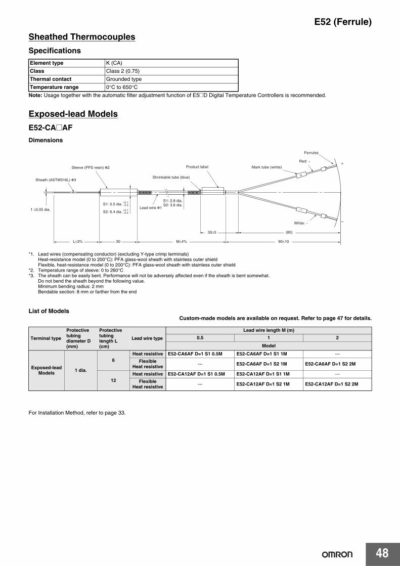
E52 (Ferrule)
48
Sheathed ThermocouplesSpecifications
Note: Usage together with the automatic filter adjustment function of E5@D Digital Temperature Controllers is recommended.
Exposed-lead ModelsE52-CA@AFDimensions
*1. Lead wires (compensating conductor) (excluding Y-type crimp terminals)Heat-resistance model (0 to 200°C): PFA glass-wool sheath with stainless outer shieldFlexible, heat-resistance model (0 to 200°C): PFA glass-wool sheath with stainless outer shield
*2. Temperature range of sleeve: 0 to 260°C*3. The sheath can be easily bent. Performance will not be adversely affected even if the sheath is bent somewhat.
Do not bend the sheath beyond the following value.Minimum bending radius: 2 mmBendable section: 8 mm or farther from the end
List of ModelsCustom-made models are available on request. Refer to page 47 for details.
For Installation Method, refer to page 33.
Element type K (CA)Class Class 2 (0.75)Thermal contact Grounded typeTemperature range 0°C to 650°C
Terminal type
Protective tubing diameter D (mm)
Protective tubing length L (cm)
Lead wire type
Lead wire length M (m)0.5 1 2
Model
Exposed-lead Models 1 dia.
6Heat resistive E52-CA6AF D=1 S1 0.5M E52-CA6AF D=1 S1 1M ---
FlexibleHeat resistive --- E52-CA6AF D=1 S2 1M E52-CA6AF D=1 S2 2M
12Heat resistive E52-CA12AF D=1 S1 0.5M E52-CA12AF D=1 S1 1M ---
FlexibleHeat resistive --- E52-CA12AF D=1 S2 1M E52-CA12AF D=1 S2 2M
Ferrules
Sheath (ASTM316L) *3
Sleeve (PPS resin) *2
Lead wire *1
S1: 2.8 dia.S2: 3.6 dia.
Shrinkable tube (blue)
Product label Mark tube (white)
Red: +
White: −
S1: 5.5 dia.
S2: 6.4 dia.
+0.1−0.3
+0.1−0.3
1 ±0.05 dia.
90±10
(80)30±5
L±3% M±4% 30

49
E52
AccessoriesCompression FittingsModel Information
Note: The Compression Fitting is not of airtight construction. Do not use the Compression Fitting for applications in which the exposure of the sensing object will cause problems.
The compression fitting is a screw that adjusts and secures the insertion length of Temperature Sensors with the above protective tubing diameters.The material of the Compression Fitting is SUS304 with internal fixing beads made of brass.
Source: JIS B 0203 (Unit: mm)
Loose FlangesModel Information
Note: 1. Use the Loose Flange in atmospheric pressure. The Loose Flange is not of airtight construction.
2. Use the Loose Flange at 400°C maximum.3. Do not apply the Loose Flange to protective tubing
diameters other than the applicable ones.
Material: Aluminum
Model Screw of part a
Applicable protective tubing
diameter
Dimensionb c d Flat diameter
Part c Part bPT 1/8 D=1.0 R 1/8 1.0 dia. 5 13 10 14 14PT 1/8 D=1.6 1.6 dia.PT 1/8 D=3.2 3.2 dia.PT 1/8 D=4.8 4.8 dia.PT 1/4 D=3.2 R 1/4 3.2 dia. 5 15 12 17 14PT 1/4 D=4.8 4.8 dia.PT 1/4 D=6.4 6.4 dia.PT 3/8 D=8 R 3/8 8 dia. 5 19 15 21 17PT 1/2 D=10 R 1/2 10 dia. 15.1 8 19 22 19M 12 D=4.8 M 12 4.8 dia. 5 15 12 17 14
Sensor side
Protective tubing dia.
Head side
a
bcd
D
Main body Retaining screwSUS304Material SUS304
Lock beadBrass
Tighten using the retaining screw to secure to the protective tubing.
Main bodySUS316
Front ringSUS316
Back ringSUS316
NutSUS316
<R1/8, 1/4, R3/8>
<1/2>
Nomi-nal
thread size
T.P.I. (No. of threads/inch)
Outer diame-ter: d
Effec-tive
diame-ter: d2
Root diame-ter: d1
Stan-dard
diame-ter
posi-tion a (from pipe end)
Mini-mum effec-tive
screw length:
f
R 1/8 28 9.728 9.147 8.566 3.97 ±0.91
2.5
R 1/4 19 13.157 12.301 11.445 6.01 ±1.34
3.7
R 3/8 19 16.662 15.806 14.950 6.35 ±1.34
3.7
R 1/2 14 20.955 19.793 18.631 8.16 ±1.81
5.0
d1d2d
a f
Tapered thread
Standard dia.
Applicable protective tubing diameter
Model
3.2 dia. MF-1 D=3.24.8 dia. MF-1 D=4.86.4 dia. MF-1 D=6.48 dia. MF-1 D=810 dia. MF-2 D=1012 dia. MF-2 D=1215 dia. MF-2 D=1522 dia. MF-2 D=22
120°Three, 5 dia.
21 dia.
D dia.
23 dia.
36
45 dia.
514
M4
Three, 6.5 dia.
54 dia.
31 dia.D dia.
35 dia.
70 dia.
24
6.6
M6
120°
MF-2MF-1
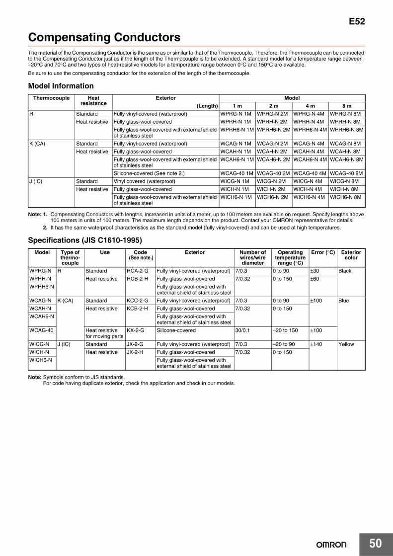
E52
50
Compensating ConductorsThe material of the Compensating Conductor is the same as or similar to that of the Thermocouple. Therefore, the Thermocouple can be connected to the Compensating Conductor just as if the length of the Thermocouple is to be extended. A standard model for a temperature range between −20°C and 70°C and two types of heat-resistive models for a temperature range between 0°C and 150°C are available.
Be sure to use the compensating conductor for the extension of the length of the thermocouple.
Model Information
Note: 1. Compensating Conductors with lengths, increased in units of a meter, up to 100 meters are available on request. Specify lengths above 100 meters in units of 100 meters. The maximum length depends on the product. Contact your OMRON representative for details.
2. It has the same waterproof characteristics as the standard model (fully vinyl-covered) and can be used at high temperatures.
Specifications (JIS C1610-1995)
Note: Symbols conform to JIS standards.For code having duplicate exterior, check the application and check in our models.
Thermocouple Heat resistance
Exterior Model(Length) 1 m 2 m 4 m 8 m
R Standard Fully vinyl-covered (waterproof) WPRG-N 1M WPRG-N 2M WPRG-N 4M WPRG-N 8MHeat resistive Fully glass-wool-covered WPRH-N 1M WPRH-N 2M WPRH-N 4M WPRH-N 8M
Fully glass-wool-covered with external shield of stainless steel
WPRH6-N 1M WPRH6-N 2M WPRH6-N 4M WPRH6-N 8M
K (CA) Standard Fully vinyl-covered (waterproof) WCAG-N 1M WCAG-N 2M WCAG-N 4M WCAG-N 8MHeat resistive Fully glass-wool-covered WCAH-N 1M WCAH-N 2M WCAH-N 4M WCAH-N 8M
Fully glass-wool-covered with external shield of stainless steel
WCAH6-N 1M WCAH6-N 2M WCAH6-N 4M WCAH6-N 8M
Silicone-covered (See note 2.) WCAG-40 1M WCAG-40 2M WCAG-40 4M WCAG-40 8MJ (IC) Standard Vinyl covered (waterproof) WICG-N 1M WICG-N 2M WICG-N 4M WICG-N 8M
Heat resistive Fully glass-wool-covered WICH-N 1M WICH-N 2M WICH-N 4M WICH-N 8MFully glass-wool-covered with external shield of stainless steel
WICH6-N 1M WICH6-N 2M WICH6-N 4M WICH6-N 8M
Model Type of thermo-couple
Use Code (See note.)
Exterior Number of wires/wire diameter
Operating temperature range (°C)
Error (°C) Exterior color
WPRG-N R Standard RCA-2-G Fully vinyl-covered (waterproof) 7/0.3 0 to 90 ±30 BlackWPRH-N Heat resistive RCB-2-H Fully glass-wool-covered 7/0.32 0 to 150 ±60WPRH6-N Fully glass-wool-covered with
external shield of stainless steelWCAG-N K (CA) Standard KCC-2-G Fully vinyl-covered (waterproof) 7/0.3 0 to 90 ±100 BlueWCAH-N Heat resistive KCB-2-H Fully glass-wool-covered 7/0.32 0 to 150WCAH6-N Fully glass-wool-covered with
external shield of stainless steelWCAG-40 Heat resistive
for moving partsKX-2-G Silicone-covered 30/0.1 −20 to 150 ±100
WICG-N J (IC) Standard JX-2-G Fully vinyl-covered (waterproof) 7/0.3 −20 to 90 ±140 YellowWICH-N Heat resistive JX-2-H Fully glass-wool-covered 7/0.32 0 to 150WICH6-N Fully glass-wool-covered with
external shield of stainless steel

E52
51
Safety Precautions
Precautions• Make sure that the protective tubing material is suitable for the
sensing object. Otherwise, the Temperature Sensor’s protective tubing may be corroded by the sensing object, preventing temperature measurement.
• Do not subject the Temperature Sensor’s protective tubing to excessive vibration, shock, or weight. Platinum resistance thermometers in particular use extremely fine resistance elements. Using these Temperature Sensors in locations subject to mechanical shock or vibration may result in broken wires.
Lead Wire Extension• Platinum Resistance Thermometers
Use lead wires for extension with the same resistance and same length for each of the three wires. The resistance of the lead wire will affect the indicated temperature when extended. Therefore, use wires with thick cores. (OMRON does not supply lead wires for extension.)
• ThermocouplesAlways use compensating conductors for thermocouples when extending the lead wires. Use a compensating conductor designed for the connected thermocouple. If you use a different type of compensating conductor from the thermocouple or if you use normal copper wires to extend, correct temperature measurement will not be possible. Also, do not connect positive and negative incorrectly.
• ThermistorsUse cables with thick core wires for the lead wires used for extension. The lead wires do not have polarity.
• Regardless of the type of Temperature Sensor used, resistance to noise will be reduced if the leads are extended. Never extend the lead any further than necessary.
Correct Use• Select a location for installing the Temperature Sensor in which the
temperature distribution of the sensing object will not change.• Make sure that the length of the Temperature Sensor’s protective
tubing is sufficient to touch or insert into the sensing object. The length of metallic protective tubing must be at least 20 times its diameter, and the length of non-metallic protective tubing must be at least 15 times its diameter. The insertion length of the special model for packaging machines (E52-CA@AY S@) is 8 mm or longer.
• Do not repeatedly bend the Temperature Sensor at the same point. The minimum allowable bending radius of sheathed Temperature Sensors is approximately five times the protective tubing diameter. Bending part of the sensor at an acute angle and then extending again may result in broken internal wires or cracks in the element. Do not bend the soldered sections. The minimum allowable bending radius of the special model for packaging machines (E52-CA@AY S@) is twice the protective tubing diameter.
• Do not bend the protective tubing while measuring low temperatures, which will cause the protective tubing to become fragile.
• Do not bend sheathed Temperature Sensors to within 100 mm of the end to protect the sensing section. Bending work can be performed on any part that is 8 mm or more from the tip of the special model for packaging machines (E52-CA@AY S@).
• Do not allow the temperature of the section connecting the protective tubing and lead wire to exceed 70°C for exposed-lead models or 100°C for heat-resistive models. The special model for packaging machines (E52-CA@AY S@) can be used at temperatures of up to 260°C.
• Do not allow the temperature of the terminal box to exceed 100°C for exposed-terminal models or 90°C for enclosed-terminal models.
• Do not subject the ceramic protective tubing of high-temperature thermocouples to sudden heating or cooling. Ceramic protective tubing has a low resistance to thermal shock. Either preheat the protective tubing or gradually heat to the required temperature.
• Do not use standard lead wires in locations subject to strong bending stress or on moving parts.
• Thermocouples with crimp terminalUse the crimp terimal only as a secondary means of securing the thermocouple. The thermocouple junction of the thermocouple is at the crimped section of the crimp terminals, so a temperature difference occurs between the screw fixating section and the thermocouple junction. Confirm the difference in temperature between the location that is to be measured and the temperature measured by the thermocouple in advance at the actual application temperature.
Mounting1. Install explosion-proof models according to the applicable laws
and regulations regarding explosion proofing.2. Sheathed Temperature Sensors with long protective tubing are
coiled for shipping. Straighten the tubing by unwinding it in the opposite direction, without twisting it.
3. Do not excessively bend the section connecting the protective tubing to the lead wires of exposed-lead wires models. Do not insert this section into the sensing object.
4. Do not pull the lead wires with force. Doing so may cause broken wires at the connected section.
5. When measuring at high temperatures that cause the protective tubing to warp, either insert the Temperature Sensor vertically or use an appropriate means to hold the Temperature Sensor in place.
6. To obtain more accurate values, maintain the temperature of the exposed protective tubing to prevent heat loss through heat dissipation.
7. If inductive noise is generated in the Temperature Sensor due to power lines or other source, either change the installation position of the Temperature Sensor and lead wires or provide a shield for the lead wires.
8. Use airtight Temperature Sensors for applications using sensing objects below room temperature, to prevent condensation within the protective tubing and faulty insulation.
9. Do not use the Temperature Sensor in locations that may expose the terminals to water or other liquid.
10.Temperature Sensors are precision devices. Do not subject the Temperature Sensors to shock. Take particular care with products that have ceramic components (ceramic protective tubing, platinum resistance thermometers).
11.Do not use ultrasonic cleaning or otherwise subject platinum resistance thermometers to extreme vibration. Doing so may cause wires to break within a short time. For such environments, consider using sheathed thermocouples, which have a superior vibration-resistant construction compared with platinum resistance thermometers and may be more suitable for the required application, depending on the level of vibration.
12.The life of the protective tubing will be significantly shortened when measuring the temperature of dissolved metals. Select protective tubing material to suit the type of dissolved metal to be measured.
13.Use the following installation methods for applications measuring the temperature of fluids.(a)Install the Temperature Sensor vertically to the flow in tubes
with relatively large diameters that enable deep insertion. (b)Install the Temperature Sensor on a diagonal against the flow in
tubes with slim diameters that do not enable deep insertion.(c)Install the Temperature Sensor into the convex section of a
bend if the tubing diameter is even thinner than in (b).
Use an installation design that provides sufficient strength margin.
Precautions for Correct Use
(a) (b) (c)

In the interest of product improvement, specifications are subject to change without notice.
ALL DIMENSIONS SHOWN ARE IN MILLIMETERS.
To convert millimeters into inches, multiply by 0.03937. To convert grams into ounces, multiply by 0.03527.

Terms and Conditions Agreement Read and understand this catalog. Please read and understand this catalog before purchasing the products. Please consult your OMRON representative if you have any questions or comments. Warranties. (a) Exclusive Warranty. Omron’s exclusive warranty is that the Products will be free from defects in materials and workmanship for a period of twelve months from the date of sale by Omron (or such other period expressed in writing by Omron). Omron disclaims all other warranties, express or implied. (b) Limitations. OMRON MAKES NO WARRANTY OR REPRESENTATION, EXPRESS OR IMPLIED, ABOUT NON-INFRINGEMENT, MERCHANTABILITY OR FITNESS FOR A PARTICULAR PURPOSE OF THE PRODUCTS. BUYER ACKNOWLEDGES THAT IT ALONE HAS DETERMINED THAT THE PRODUCTS WILL SUITABLY MEET THE REQUIREMENTS OF THEIR INTENDED USE. Omron further disclaims all warranties and responsibility of any type for claims or expenses based on infringement by the Products or otherwise of any intellectual property right. (c) Buyer Remedy. Omron’s sole obligation hereunder shall be, at Omron’s election, to (i) replace (in the form originally shipped with Buyer responsible for labor charges for removal or replacement thereof) the non-complying Product, (ii) repair the non-complying Product, or (iii) repay or credit Buyer an amount equal to the purchase price of the non-complying Product; provided that in no event shall Omron be responsible for warranty, repair, indemnity or any other claims or expenses regarding the Products unless Omron’s analysis confirms that the Products were properly handled, stored, installed and maintained and not subject to contamination, abuse, misuse or inappropriate modification. Return of any Products by Buyer must be approved in writing by Omron before shipment. Omron Companies shall not be liable for the suitability or unsuitability or the results from the use of Products in combination with any electrical or electronic components, circuits, system assemblies or any other materials or substances or environments. Any advice, recommendations or information given orally or in writing, are not to be construed as an amendment or addition to the above warranty. See http://www.omron.com/global/ or contact your Omron representative for published information. Limitation on Liability; Etc. OMRON COMPANIES SHALL NOT BE LIABLE FOR SPECIAL, INDIRECT, INCIDENTAL, OR CONSEQUENTIAL DAMAGES, LOSS OF PROFITS OR PRODUCTION OR COMMERCIAL LOSS IN ANY WAY CONNECTED WITH THE PRODUCTS, WHETHER SUCH CLAIM IS BASED IN CONTRACT, WARRANTY, NEGLIGENCE OR STRICT LIABILITY. Further, in no event shall liability of Omron Companies exceed the individual price of the Product on which liability is asserted. Suitability of Use. Omron Companies shall not be responsible for conformity with any standards, codes or regulations which apply to the combination of the Product in the Buyer’s application or use of the Product. At Buyer’s request, Omron will provide applicable third party certification documents identifying ratings and limitations of use which apply to the Product. This information by itself is not sufficient for a complete determination of the suitability of the Product in combination with the end product, machine, system, or other application or use. Buyer shall be solely responsible for determining appropriateness of the particular Product with respect to Buyer’s application, product or system. Buyer shall take application responsibility in all cases. NEVER USE THE PRODUCT FOR AN APPLICATION INVOLVING SERIOUS RISK TO LIFE OR PROPERTY OR IN LARGE QUANTITIES WITHOUT ENSURING THAT THE SYSTEM AS A WHOLE HAS BEEN DESIGNED TO ADDRESS THE RISKS, AND THAT THE OMRON PRODUCT(S) IS PROPERLY RATED AND INSTALLED FOR THE INTENDED USE WITHIN THE OVERALL EQUIPMENT OR SYSTEM. Programmable Products. Omron Companies shall not be responsible for the user’s programming of a programmable Product, or any consequence thereof. Performance Data. Data presented in Omron Company websites, catalogs and other materials is provided as a guide for the user in determining suitability and does not constitute a warranty. It may represent the result of Omron’s test conditions, and the user must correlate it to actual application requirements. Actual performance is subject to the Omron’s Warranty and Limitations of Liability. Change in Specifications. Product specifications and accessories may be changed at any time based on improvements and other reasons. It is our practice to change part numbers when published ratings or features are changed, or when significant construction changes are made. However, some specifications of the Product may be changed without any notice. When in doubt, special part numbers may be assigned to fix or establish key specifications for your application. Please consult with your Omron’s representative at any time to confirm actual specifications of purchased Product. Errors and Omissions. Information presented by Omron Companies has been checked and is believed to be accurate; however, no responsibility is assumed for clerical, typographical or proofreading errors or omissions.
2018.2
In the interest of product improvement, specifications are subject to change without notice.
OMRON Corporation Industrial Automation Company http://www.ia.omron.com/
(c)Copyright OMRON Corporation 2018 All Right Reserved.


![Product News 2013-2 (IAB, for ENG)2).pdf · Model E52-CA[]C-N-19, Model E52-IC[]C-N-19, E52-CA[]D-N-2, Model E52-IC[]D-N-2, Model E52-CA[]F-N-2, Model E52-IC[]F-N-2 * For some models](https://static.fdocuments.us/doc/165x107/5f51ffeed2aef822ac7c2c4c/product-news-2013-2-iab-for-eng-2pdf-model-e52-cac-n-19-model-e52-icc-n-19.jpg)