List of figures - Columbia of Columbia Engineering Regulations - 16-1 City oF Columbia ENgiNEEriNg...
42
Figure 16-1. Typical Service Connecons 16-20 Figure 16-2. Typical Meter Box for Meters 3” and Above 16-21 Figure 16-3. Typical Repair Secons 16-22 Figure 16-4. Standard Hydrant Detail 16-23 Figure 16-5. Alternate Method of Fire Hydrant Installaon 16-24 Figure 16-6. Typical Permanent Repair Secons 16-25 Figure 16-7. Typical Repair Secons 16-26 Figure 16-8. Typical Repair Secons 16-27 Figure 16-9. Air Release Valve 16-28 Figure 16-10. Valve Box Protector Ring Detail; Gate Valve Box Detail 16-29 Figure 16-11. Buerfly Valve Box Detail 16-30 Figure 16-12. Concrete Pipe Encasement 16-31 Figure 16-13. Standard Pipe Bedding and Backfilling Detail - Backfull for Ducle Iron Pipe and Backfill for Gray Cast Iron Pipe 16-32 Figure 16-14. Standard Pipe Bedding and Backfilling Detail - Backfill for Prestressed Concrete Cylinder Pipe 16-33 Figure 16-15. Standard Pipe Bedding and Backfilling Detail - PVC Pipe 16-34 Figure 16-16. Thrust Block Detail - Plug and Dead End Mains 16-35 Figure 16-17. Thrust Block Details - Concrete Blocking Dimensions 16-36 Figure 16-18. Top Slab - Hatch Reinforcement Detail 16-37 Figure 16-19. Meter Pit in Traffic Area 16-38 Figure 16-20. Meter Vault Detail With True By-Pass 16-39 Figure 16-21. Roung of Tracer Wire Inside Valve Box 16-40 LIST OF FIGURES Figure Descripon Page No. City of Columbia Engineering Regulaons - 16-i 16.1 General 16-1 16.2 Construcon Materials 16-3 16.3 Construcon Methods 16-9 16.4 Tesng and Disinfecon 16-14 16.5 Measurement and Payment 16-15 16.6 General Warranty for Three Years Aſter Compleon of Contract 16-19 City oF Columbia ENgiNEEriNg rEgulatioNs Part 16: sPECiFiCatioNs For WatEr DistributioN systEm, matErials, aND CoNstruCtioN tablE oF CoNtENts Paragraph Descripon Page No.
Transcript of List of figures - Columbia of Columbia Engineering Regulations - 16-1 City oF Columbia ENgiNEEriNg...

Figure 16-1. Typical Service Connections 16-20Figure 16-2. Typical Meter Box for Meters 3” and Above 16-21Figure 16-3. Typical Repair Sections 16-22Figure 16-4. Standard Hydrant Detail 16-23Figure 16-5. Alternate Method of Fire Hydrant Installation 16-24Figure 16-6. Typical Permanent Repair Sections 16-25Figure 16-7. Typical Repair Sections 16-26Figure 16-8. Typical Repair Sections 16-27Figure 16-9. Air Release Valve 16-28Figure 16-10. Valve Box Protector Ring Detail; Gate Valve Box Detail 16-29Figure 16-11. Butterfly Valve Box Detail 16-30Figure 16-12. Concrete Pipe Encasement 16-31Figure 16-13. Standard Pipe Bedding and Backfilling Detail - Backfull for Ductile Iron Pipe and
Backfill for Gray Cast Iron Pipe 16-32Figure 16-14. Standard Pipe Bedding and Backfilling Detail - Backfill for Prestressed Concrete
Cylinder Pipe 16-33Figure 16-15. Standard Pipe Bedding and Backfilling Detail - PVC Pipe 16-34Figure 16-16. Thrust Block Detail - Plug and Dead End Mains 16-35Figure 16-17. Thrust Block Details - Concrete Blocking Dimensions 16-36Figure 16-18. Top Slab - Hatch Reinforcement Detail 16-37Figure 16-19. Meter Pit in Traffic Area 16-38Figure 16-20. Meter Vault Detail With True By-Pass 16-39Figure 16-21. Routing of Tracer Wire Inside Valve Box 16-40
List of figuresFigure Description Page No.
City of Columbia Engineering Regulations - 16-i
16.1 General 16-116.2 Construction Materials 16-316.3 Construction Methods 16-916.4 Testing and Disinfection 16-1416.5 Measurement and Payment 16-1516.6 General Warranty for Three Years After Completion of Contract 16-19
City oF Columbia ENgiNEEriNg rEgulatioNsPart 16: sPECiFiCatioNs For WatEr DistributioN systEm,
matErials, aND CoNstruCtioNtablE oF CoNtENts
Paragraph Description Page No.

Table 16-1. Steel Casing Pipe Sizing 16-5Table 16-2. Trench Widths 16-11
List of tabLestable Description Page No.
City of Columbia Engineering Regulations - 16-ii

City of Columbia Engineering Regulations - 16-1
City oF Columbia ENgiNEEriNg rEgulatioNsPart 16: sPECiFiCatioNs For WatEr DistributioN systEm,
matErials, aND CoNstruCtioN16.1 general
These specifications contemplate the complete installation of certain water mains, valves and appurtenances incident to the construction of water main extensions to be connected to the City of Columbia, South Carolina, Water Works System. Construction detail drawings WC#1 through WC#11, WC#13 through WC#18 attached are a part of these specifications. No project will be constructed that does not comply with Part 2, Water Distribution System Design Standards. It is understood that all standards cited in the text shall refer to the latest revision of that standard under the same standard number or to superseding standards under a new number.
16.1.1 Pipe shall be installed at the locations shown on the plans and to the position, alignment and grade shown thereon, or in the event of grade conflict, as directed by the Engineer. All pipe, fittings, packing, jointing materials, valves, and fire hydrants shall conform to section C of the AWWA Standards. All associated hardware shall have a minimum working pressure of Class 250.
16.1.1.1 All pipe used must have working pressure rating at least two times the expected static pressure.
16.1.2 All pipe, special castings and fittings for water distribution shall be furnished in weights, classes, and/or thickness in accordance with specifications as outlined herein and in the proposal form.
16.1.3 Pipe four (4) inches through (8) inches in diameter may be PVC C-900 or ductile iron pipe. Pipe twelve (12) inches in diameter or larger shall be ductile iron pipe. All pipe used shall meet all specifications listed herein.
16.1.3.1 The City of Columbia does not accept 1”, 1.25”, 2”, 2.5”, 3”, 10”, 14” and 20” pipe for use in its water distribution system for water mains.
16.1.4 Water used for construction, testing and disinfection will be furnished by the City through approved connections to the City water system. Check valves to reduce possibility of contamination will be furnished by the contractor when directed by the City Engineer. Water mains, which have been previously used for conveying potable water, may be reused provided they meet applicable criteria from AWWA Section C, ANSI/NSF 61, and ASTM D1786 or D2241. The mains must be thoroughly cleaned and restored practically to their original condition. Otherwise, only the use of new materials must be specified.
16.1.5 All materials furnished by the contractor shall be delivered and distributed at the site by the contractor. Materials furnished by the owner shall be picked up by the contractor at points designated by the City and hauled to the distribution site.

City of Columbia Engineering Regulations - 16-2
16.1.6 In distributing the material at the site of the work, each piece shall be unloaded opposite or near the place where it is to be laid in the trench.
16.1.7 Pipe shall be so handled that the coating and lining will not be damaged. If, however, any part of the coating or lining is damaged, the repair shall be made by the contractor at his expense in a manner satisfactory to the engineer.
16.1.8 The water main shall be laid and maintained to the required lines and grades with fittings, valves, and hydrants at the required locations; spigots centered in bells; and all valve and hydrant stems plumb.
16.1.9 The contractor shall proceed with caution in the excavation and preparation of the trench so that the exact location of underground structures, both known and unknown, may be determined, and he shall be held responsible for the repair of such structures when broken or otherwise damaged.
16.1.10 All pipe shall be laid to the depth shown on the contract drawings. Any variations therefrom shall be made only at the order of the engineer.
16.1.11 Ledge rock, boulders, and large stones shall be removed to provide a clearance of at least six inches below and on each side of all pipe, valves, and fittings for pipes 24 inches in diameter or less, and nine inches for pipes larger than 24 inches in diameter. The specified minimum clearances are the minimum clear distances that will be permitted between any part of the pipe and appurtenances being laid and any part, projection, or point of such rock, boulder, or stone.
16.1.12 The trench shall be dug so that the pipe can be laid to the alignment and depth required, and it shall be excavated only so far in advance of pipelaying as specified or permitted by the engineer. The trench shall be so braced and drained that the workmen may work in it safely and efficiently. It is essential that the discharge of the trench dewatering pumps be conducted to natural drainage channels, drains, or storm sewers.
16.1.13 The width of the trench shall be ample to permit the pipe to be laid and joined properly, and the backfill to be placed and compacted as specified. Trenches shall be of such extra width, when required, as will permit the convenient placing of timber supports, sheeting and bracing, and handling of specials. No extra payment will be allowed for this work, the cost of which will be included in the contractor’s unit bid prices.
16.1.14 Galvanized steel pipe is not acceptable for usage within the City of Columbia’s water system. Ductile iron, PVC-C900 pipe and HDPE (main lines) and CTS 3408 tubing (3/4” and 2” service lines) are acceptable.
16.1.15 Post hydrants shall be installed on all dead end water mains greater than 200 feet in length. All post hydrants must meet current City Regulations (Part 16, Standard Detail). Where dead-end mains 8” or larger occur, they shall be provided with a hydrant for flushing purposes.

City of Columbia Engineering Regulations - 16-3
16.1.15.1 Permanent post hydrants shall be installed in locations that will prevent potential drainage problems. The runoff shall not be allowed to drain into existing or future yards. If possible, the post hydrant shall be located in an area which allows the flow to be directed into drainage structures (catch basins, etc.). Post hydrants shall not be directed toward creeks but over ground where possible. The City Engineer reserves the right to disapprove post hydrant locations based on potential drainage problems.
16.2 Construction materials
16.2.1 All materials and products which come into contact with drinking water must be certified as meeting the specifications of the American National Standards Institute/National Sanitation Foundation (ANSI/NSF) Standard 61, Drinking Water System Components – Health Effects.
16.2.2 “Lead free” pipe, pipe fittings, solder and flux must be used in installation of all water mains. Pipe and pipe fittings containing no more than 8.0 percent lead are considered “lead free”. Solder and flux containing no more than 0.2 percent lead are considered “lead free”.
16.2.3 Gaskets, O-rings, and other products used for jointing pipes, setting meters or valves, or other appurtenances which will expose the material to water shall not be made of natural rubber or any other material which will support microbiological growth. Lubricants which will support microbiological growth shall not be used for slip-on joints. The use of vegetable shortening is prohibited.
16.2.4 Ductile Iron Pipe
16.2.4.1 Ductile iron pipe will be designed in accordance with ANSI specification A US Pipe 21.50 (AWWA C150) for a normal working pressure of 150 psi and Laying Condition “2”. The pipe shall be manufactured in accordance with ANSI specification A 21.51 (AWWA C151). Joints shall be Bell and Spigot, Push-on (McWane Tyton American Fastite, or equivalent), or Mechanical; unless otherwise called for on the proposal form. Pipe will be cement lined and seal-coated in accordance with ANSI specification A 21.4 (AWWA C104). Pipe used must have working pressure rating at least two times the expected static pressure.
16.2.5 Reinforced Concrete Pipe
16.2.5.1 Reinforced concrete pipe is not approved for water distribution system construction.
16.2.6 Asbestos-Cement Pipe
16.2.6.1 Asbestos–cement pipe is not approved for water distribution system construction.
16.2.7 Polyvinyl Chloride (PVC) Pipe
16.2.7.1 Polyvinyl chloride pipe shall conform to the specifications of the American Water Works Association Standard for Polyvinyl Chloride (PVC) Pressure pipe, 4” through 8”, for water, specification C900, with the following supplemental specifications:

City of Columbia Engineering Regulations - 16-4
16.2.7.2 All polyvinyl chloride pipe shall be Pressure Class 150 and shall meet the requirements of DR18. Joints shall be Bell and Spigot, similar to Johns-Manville’s “Blue Brute”, Robintech’s “White Knight”, or approved equal. Pipe used must have working pressure rating at least two times the expected static pressure. PVC pipe is not acceptable for usage where static pressure is above 75 psi.
16.2.7.3 Installation shall be in accordance with ANSI/ASTM D 2321. Only Class I, II, and III embedment materials, as defined in paragraph 6 and Figure 1, may be used in bedding, haunching, or initial backfill.
16.2.7.3.1 When installing C900 PVC pipe, all fittings and valves are to be installed with retaining glands (Megalugs or approved equal), in addition to concrete thrust blocks (see section 3.10).
16.2.7.4 Where PVC or Polyethylene pipe is used in water main construction, a continuous #12 gauge blue insulated cooper tracer wire, approved by the manufacturer for direct burial, shall be installed in the trench and taped to the top of the pipe using 2” duct tape. The tape shall be wrapped a minimum of 2 times around the pipe. The tracer wire shall terminate at each valve and meter and be arranged to allow connection of equipment for tracking pipe and prevent interference of operating the valve or meter. Tracer wire shall also be installed to the ends of the service lines. Underground waterproof connectors must be used on all splices. All connectors must be thoroughly wrapped in electrical tape.
16.2.7.5 PVC pipe is not approved for use within 15 feet of a building or structure.
16.2.8 Fittings
16.2.8.1 All fittings shall be in accordance with ANSI specification A21.10 (AWWA C110) and ANSI specification A21.11 (AWWA C111). The joints shall be Bell and Spigot, Push-on (McWane Tyton, American Fastite, or equivalent) or Mechanical; unless otherwise called for on the proposal form. Compact ductile iron mechanical joint fittings, shall be in accordance with ANSI specifications A21.53 (AWWA C153). Size on size tapping sleeves shall be mechanical joints. Smaller taps onto larger lines may use fabricated tapping sleeves. All main line taps are required to use a tapping saddle.
16.2.8.2 Fittings will be cement-lined and seal-coated in accordance with ANSI specification A21.4 (AWWA C104).
16.2.8.3 Fittings, four inch through 24 inch sizes, shall be Pressure Class 350 and 30 inch through 48 inch sizes shall be Pressure Class 250.
16.2.9 Specials and Fitting for Reinforced Concrete Pipe
16.2.9.1 Specials and fittings for reinforced concrete steel cylinder pipe shall conform to the details in accordance with American Water Works Association’s standard specifications C 301.

City of Columbia Engineering Regulations - 16-5
16.2.10 Service Lines
16.2.10.1 Service lines to each lot shall be provided to the property lines or edge of easements where called for on the plans or instructed by the City Engineer. Service line connections shall be spaced to prevent cracking on PVC pipe. Spacing shall be as determined by pipe manufacturer’s criteria and approved by the City Engineer.
16.2.10.1.1 Service lines 1 inch and smaller in diameter will be type K soft copper or Polyethylene PE 3408 Class 160-SDR-9 cts. Service connections to mains of all materials shall be made by the use of a service tapping saddle and corporation stop
16.2.10.1.2 Installation fittings for polyethylene tubing will be brass fittings with compression connections. Corporation stops ¾ inch through 2 inch size shall be Mueller P-25008, McDonald 4701B-22 or 4704B-22, or approved equal meeting class 250. Curb stops ¾ inch through 2 inch size shall be Mueller B25170, Hays 4302 CJ, Ford B41-333W, McDonald 6102WT or 6102W, or approved equal. All compression connections are to be used with a steel or plastic (maximum of 1” in length) insert liner at each connection made.
16.2.10.1.3 Service lines one and one half (1 ½”) inches through two (2”) inches in diameter may be polyethylene tubing or CTS 3408 tubing.
16.2.10.1.4 Service lines 4 inches and larger must meet same requirements as for water mains.
16.2.10.1.5 Backflow prevention devices are required for all water service connections. Double check valve and reduced pressure principle backflow prevention assemblies must be selected from the SCDHEC approved list. Also, each assembly must be tested by a certified tester upon installation, once annually thereafter, and after any repairs. Refer to Part 12, Section 12.9 – Cross Connection Control/Backflow Prevention.
16.2.10.1.6 Backflow preventer and ¾ -inch pressure reducing valve will be installed on homeowner side of the water meter. Contractor to provide warranty for 3 months after final completion of project.
16.2.11 Steel Casing Pipe
16.2.11.1 Steel casing pipe for underground installation by dry bore and jacking shall be manufactured in accordance with ANSI specification A53. The steel pipe shall be Type S, Grade B, plain end beveled. Steel casing pipe, sizes 28 inches and larger shall conform to standard pipe dimensions contained in USA Standard USAS B36. All steel casing pipe shall be furnished in 20 foot lengths, all joints welded. The minimum wall thicknesses shall be as follows: table 16-1. Steel Casing Pipe Sizing
Normal Diameter (inches)
Normal Thickness (inches)
Under 14 0.25014 and 16 0.281

City of Columbia Engineering Regulations - 16-6
Normal Diameter (inches)
Normal Thickness (inches)
18 0.31220 0.31222 0.34424 0.37526 0.375
28 and 30 0.40632 0.438
34 and 36 0.46938, 40 and 42 0.500
16.2.11.2 When casing is installed without benefit of a protective coating, and said casing is not cathodically protected, the wall thickness shown above shall be increased to the nearest standard size which is a minimum of 0.063 inch greater than the thickness shown except for diameters under 12 ¾ inches.
16.2.12 Mechanical Joint Restraints
16.2.12.1 Restraints for ductile iron pipe shall be mechanical joint restraints conforming to the requirements of ASTM A536-84. Restraints shall be restrain type such as “Mega-Lug” by EBAA Iron Company or approved equal.
16.2.12.2 Joints shall be restrain type such as “Lok-Fast” or “Lok-Ring” by American Cast Iron Company or “TR FLEX” by U.S. Pipe and Foundry Company. All bolts shall be pre-coated Coating shall be of the same grade and quality as the coating on the outside of the pipe.
16.2.12.3 Mechanical joint restraints shall be used at all valves and fittings or as directed by the Engineer.
16.2.12.4 Mechanical couplings shall be installed in accordance with the mechanical coupling manufacturer’s recommended procedures.
16.2.13 Fire Hydrants (Standard Details)
16.2.13.1 All fire hydrants shall conform to the American Water Works Association’s standard C502 and shall be guaranteed for two hundred fifty (250) pounds water working pressure. Each hydrant shall have a six (6) inch hub connection, one standard pumper nozzle and two nozzles for 2 ½ inch diameter hose. Hose threads to be National Standard.
16.2.13.2 Hydrants shall be of the size commercially recognized as five and one fourth (5 ¼) inch hydrants. Hydrants shall include all materials necessary to bring the hydrant to its location above finished grade, including extensions or offset fittings. Provide an offset fitting at sloped areas where required for the hydrant connections to be located above finished grade. Locate the offset between the shut-off valve and hydrant. Provide Grade Lok as manufactured by Assured Flow Sales, Inc. or approved equal.

City of Columbia Engineering Regulations - 16-7
16.2.13.2.1 During fire hydrant installation, all fire hydrant valves are to be restrained as close to the main line as possible with an approved hydrant tee.
16.2.13.3 Operating nuts shall open right.
16.2.13.4 Hydrants approved for use are as follows:Mueller – CenturionM&H Style 929 Reliant (Epoxy Shoe Only)CLOW – Medallion SeriesAmerican-Darling B-84-B-5
16.2.13.5 Additional fire hydrants will be reviewed for approval upon request. Written approval from the City Engineer must be obtained in order to use any fire hydrant not listed in Section 2.12.4.
16.2.14 Gate Valves (Standard Detail)
16.2.14.1 Gate valves 3” through 12” may be resilient seated gate valves conforming to the American Water Works Association standard specification C 509. Resilient seated valves shall have internal ferrous metal surfaces fully coated with durable epoxy and have integrally cast bronze stem nut and be designed for external stern failure when excessive closing torque is applied with no failure of the pressure retaining parts.
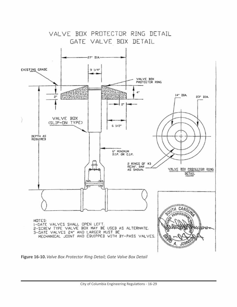
16.2.14.2 All gate valves shall be equipped with cast iron valve boxes and covers of the adjustable or extension type, similar to the type now being used where required by the City of Columbia and weighing approximately ninety-three pounds. Provide and install an extension stem for all gate valves where the operator nut is more than 60” below finished grade. Valves shall open left.
16.2.14.3 Gate valves 24 inches and larger shall be mechanical joint and equipped with beveled gears enclosed in grease cases with grease fittings and with by-pass, scrapers and rollers. These valves shall have two such valve boxes each, one for operating stem on bevel gear and one by-pas valve.
16.2.14.4 Hand wheel valves are not approved for use in the City of Columbia water system other than the meter pit.
16.2.15 Butterfly Valves
16.2.15.1 Butterfly valves shall meet the American Water Works Association standard specification C504 – rubber seat for Class 250. The butterfly valves shall be mechanical joint, flanged, push-on or combinations thereof, and furnished with manual operators. Provide and install an extension stem for all butterfly valves where the operator nut is more than 60” below finished grade. Valves shall open left.
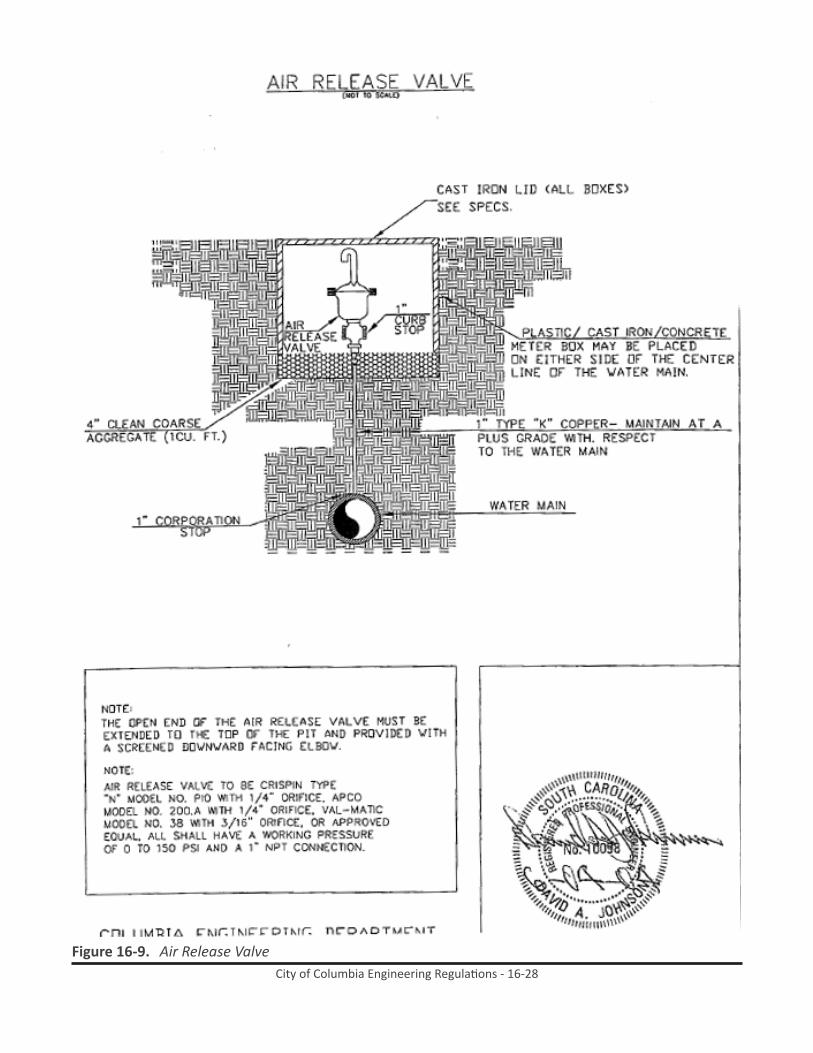
16.2.16 Air Release Valves

City of Columbia Engineering Regulations - 16-8
16.2.16.1 At each high point along the water main the Contractor shall install an air release valve as follows:
16.2.16.1.1 Crispin type “N”, Model No. P10 with ¼ inch orifice; APCO Model No. 200A with ¼ inch orifice, or Val-Matic Model No. 38 with 3/16 inch orifice, or approved equal, are authorized for use. All shall have a working pressure of 0 to 150 psi, and a 1 inch NPT connection. The valve shall be attached to the pipe line by means of a 1 inch corporation stop, 1 inch type K copper tubing or polyethylene tubing, 1 inch curb stop, and shall be housed in a cast iron meter box. Contractor is to coordinate the location of the air release valve so that it is located on the high point of the water main as it is actually installed in the field. See Standard Detail)
16.2.16.1.2 Automatic air release valves shall not be used in situations where flooding of the manhole or chamber may occur.
16.2.17 Check Valves
16.2.17.1 Check valves shall be approved by City Engineer prior to installation of the City’s system.
16.2.17.2 Check valves must be accessible.
16.2.18 Polyethylene Encasement
16.2.18.1 Ductile iron pipe, fittings, valves and other appurtenances installed at locations where the water main crosses an existing metal utility line shall be encased in polyethylene in accordance with ANSI and AWWA C105 where called for on the plan.
16.2.19 Concrete
16.2.19.1 This section includes all concrete work required, of every description, shown or specified, including pavements, bedding concrete, thrust blocks, etc. All materials incorporated in the concrete shall conform to the South Carolina Department of Transportation Standard Specification for Highway Construction, latest edition.
16.2.20 Reinforcing Steel
16.2.20.1 Reinforcing steel shall be of new billet steel intermediate grade made by the open hearth process, conforming to the requirements of the “Standard Specifications for Billet Steel Concrete Reinforcement Bars”, Serial Designation C15-33 of the ASTM A615. Bars must be deformed in rolling, and the design of the deformation shall be in accordance with ASTM Designation A615. In addition to the reinforcing indicated on the plans, the Contractor shall furnish all necessary support bars, tie bards, etc., required for properly supporting and spacing the bars in the forms. The reinforcement will be subject to field inspection for rust, shape and dimensions.
16.2.21 Meter Pits

City of Columbia Engineering Regulations - 16-9
16.2.21.1 For separate lines designed for the meter pit, there shall be a valve at the tee. If the line is not designated only for the pit there shall be a valve installed prior to the pit. See detail.
16.2.21.2 If a prefabricated meter lid is used the lid shall have a 48” aluminum opening (see Standard Detail
16.2.21.3 Meter pits shall be located inside the right-of-way (adjacent to the right-of-way/property line) and outside of traffic and parking areas. Special approval from the City will need to be obtained if located in traffic area.
16.2.21.4 If special approval is granted, meter pits located in traffic areas shall be designed to meet all load bearing requirements (see Standard Detail.)
16.2.21.5 See Standard Detail for by pass line requirements pertaining to facilities which are 24 hour or critical operations.
16.3 Construction methods
16.3.1 Clearing and Grubbing
16.3.1.1 The contractor shall do all necessary clearing and grubbing along the line of the work; however, he will not be allowed to remove or otherwise damage any trees or shrubbery other than those which, in the opinion of the City Engineer in conjunction with the Forestry and Beautification Superintendent, are necessary for the protection of the work. All work shall be in accordance with easement agreements between the City and property owners. Easements may be reviewed in the office of the City Engineer. One copy will be furnished to the successful bidder on his request.
16.3.1.2 Upon completion of the work the Contractor will be required to dispose of all surplus material and rubbish and restore all public and private property which has been damaged in the course of the work. The work and services outlined under “Clearing and Grubbing” will not be paid for as such and the Contractor shall distribute the cost for performing such work and services among the various items on which unit prices are called for.
16.3.2 Trenching
16.3.2.1 All trenches and excavation shall be backfilled immediately after the pipes are laid therein, unless other protection of the pipe line is directed. The backfill material shall be selected and deposited with special attention to proper bedding of the pipe. Except where special methods of bedding and tamping are provided for, clean earth, sand or rock dust shall be solidly tamped about the pipe. Minimum cover shall be as follows:
16.3.2.2 Minor subdivision piping, 8 inch diameter and less, 30 inch minimum cover.
16.3.2.3 Twelve-inch diameter, 36-inch minimum cover.

City of Columbia Engineering Regulations - 16-10
16.3.2.4 Sixteen inch diameter and larger, 48 inch minimum cover.
16.3.2.5 Piping 12” or larger to be located outside a dedicated easement (inside dedicated right-of-way) shall have a 48 inch minimum cover. Piping less than 12” to be located shall have a 36” minimum cover. This depth shall be measured from the low point of the cross section of the existing road right-of-way. The road right-of-way shall include embankments, ditches and other such appurtenances adjacent to the road. The Contractor shall be required to coordinate this work with the Engineer/Inspector. Any piping to be located inside SCDOT right-of-way must meet SCDOT requirements.
16.3.2.6 The Contractor shall be required to have all road crossings tested by an approved laboratory that will certify that the backfill material has been compacted to 95% maximum density as determined by AASHTO-99 procedures.
16.3.2.7 Special conditions other than those listed shall be approved in writing by the City Engineer.
16.3.2.8 Separation of water mains and sanitary sewers shall be in accordance with “Ten State Standards”.
16.3.2.9 Trenching shall be in accordance with AWWA C-600, Section 3.1 and 3.2. Minimum trench width shall be pipe diameter plus two feet. All excavated materials which are unsuitable for backfilling the trench shall be wasted in an area provided by the Contractor and approved by the City Engineer.
16.3.2.10 The bottom of the trenches shall be graded in such a manner as to provide a firm bearing for the pipe. The use of boards or other material to support the pipe will not be permitted. Continuous and uniform bedding shall be provided in the trench for all buried pipe. Any soft or unstable foundations encountered shall be removed and replaced with suitable material and thoroughly compacted. Bell holes shall be of sufficient size to allow proper construction.
16.3.2.11 The Contractor shall perform all excavation of every description and of whatever substances encountered, to the depth indicated on the drawings or as otherwise specified by the City. During excavation, material suitable for backfilling shall be piled in an orderly manner, a sufficient distance from the banks of the trench to avoid overloading and to prevent slides or cave-ins. OSHA regulations shall govern.
16.3.2.12 Where trenching is in a paved area, the pavement and base shall be removed a minimum of 12 inches on each side of the trench in order to place the edge of the new paving upon undisturbed soil. All work in streets shall conform to most recent Code of Ordinances for the City of Columbia.
16.3.2.13 Where trenching is adjacent to slopes, either cuts or fills, the Contractor will not be permitted to level or alter or otherwise damage these slopes for the purpose of using any equipment such as trenching machines or back-hoes, unless special permission, in writing, is given the Contractor by the City Engineer, and the Contractor is cautioned to examine the locations of the proposed water lines with this in mind.

City of Columbia Engineering Regulations - 16-11
16.3.2.14 Trench widths shall be as follows when construction is under an improved surface: table 16-2. Trench Widths
Nominal Pipe Diameter (inches)
Minimum in Earth and Rock (inches)
4 366 368 36
12 3616 4018 4224 5430 6036 6642 7248 7854 8460 96
16.3.2.15 To protect persons from injury and to avoid property damage, adequate barricades, construction signs, torches, warning lanterns and guards as required shall be placed and maintained during the progress of the construction work. All material piles, equipment, and pipe that may serve as obstructions to traffic shall be enclosed by fences or barricades and shall be protected by proper lights when the visibility is poor. Safety rules and regulations of local authorities shall be observed.
16.3.2.16 All excavations shall be dewatered properly before laying pipe. Where running sand is encountered, dewatering shall be done by well pointing whenever possible. Where soil conditions are not favorable for use of well points, French drains of crushed stone or gravel shall be constructed to suitably located sumps and the water removed by bailing or pumping.
16.3.3 Backfilling and Unsuitable Backfull Material
16.3.3.1 Where the excavated material is unsuitable for backfill purposes, the Contractor shall furnish satisfactory material wasted from trench excavation in other locations, or from other sources selected by him and approved by the City Engineer. Approved flowable fill material may be required depending on location and conditions of applicable permits.
16.3.3.2 Backfill shall be in accordance with Section 3.5 AWWA C-600. The Contractor shall provide geotechnical tests confirming backfill is suitable upon request by the City.
16.3.3.3 In backfilling trenches the material shall first be carefully placed around the pipe and thoroughly tamped up to the elevation of the top of the pipe in layers not exceeding six inches in thickness by means of power-driven tampers; the remainder of the trench shall then be filled in layers not more than six inches in thickness and each layer thoroughly tamped with power-driven tampers. Where backfilling material is too wet for satisfactory

City of Columbia Engineering Regulations - 16-12
tamping, the material shall be allowed to dry or dry material shall be hauled in. The Contractor will be held responsible for settlement over all trenches and, where necessary, he shall add material which shall be thoroughly tamped in the prescribed manner.
16.3.3.4 All backfilling of excavated portions requiring pavement replacement shall be mechanically tamped in six inch layers, using heavy duty tampers, such as pneumatic tampers with tamping foot attachment. Each layer shall be thoroughly tamped to a density equivalent to at least 95 percent of an AASHTO T-00-49 Proctor Curve.
16.3.3.5 The Contractor will be required to furnish, maintain and operate at all times such equipment as is necessary to keep the streets along the route of operation in good condition throughout the life of this contract. This work and service will not be paid for as such and the Contractor shall distribute his cost for performing such work and services among the various items on which unit prices are called for.
16.3.3.6 Excavated rock shall not be mixed with material selected for the tamped backfill under and around the pipe. Stones, other than crushed bedding, shall not come in contact with the pipe and shall not be within 6 inches of the pipe.
16.3.3.7 All surplus rock excavated shall be removed and disposed at locations approved by the City.
16.3.3.8 Whenever the trenches have not been properly filled, or if settlement occurs, they shall be refilled, smoothed off and finally made to conform to the surface of the ground by the Contractor. Backfill shall be carefully placed and the original surface restored to the full satisfaction of the Engineer.
16.3.4 Rock Excavation
16.3.4.1 Wherever “rock” is used as the name of an excavated material, it shall mean boulders or pieces of rock, concrete, or masonry measuring one-half (1/2) cubic yard or more, hard shale or solid ledge rock and masonry which, in the opinion of the Engineer, requires for its removal the continuous use of pneumatic tools or drills and blasting.
16.3.4.2 Before payment is allowed for rock excavation, the contractor shall be required to demonstrate that the material cannot be removed “by hand pick” or by power operated excavator or shovel. No payment will be made for Rock Excavation unless air tools or explosives were used by the contractor. No payment will be made for Rock Excavation unless the Engineer determines that the material meets the above criteria, and gives written approval for payment prior to excavation.
16.3.4.3 Should the Contractor elect to use explosives to loosen rock or for any other purposes in the prosecution of the work, he shall obtain the required permits and the written permission of the Engineer. The City Fire Chief and Police Chief shall be notified. If construction is outside the City Limits, the Contractor shall be responsible for determining whether a County permit is required and for obtaining any permit so required. The Contractor’s methods and procedures in the transportation, handling,
City of Columbia Engineering Regulations - 16-13
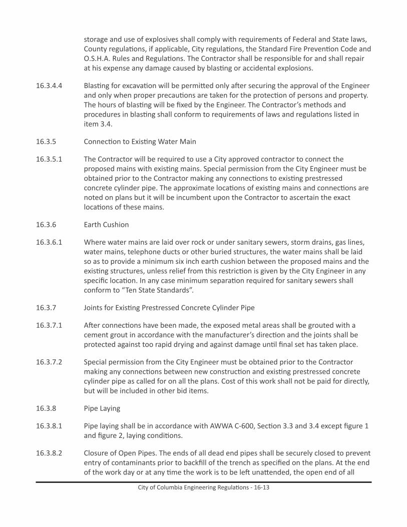
storage and use of explosives shall comply with requirements of Federal and State laws, County regulations, if applicable, City regulations, the Standard Fire Prevention Code and O.S.H.A. Rules and Regulations. The Contractor shall be responsible for and shall repair at his expense any damage caused by blasting or accidental explosions.
16.3.4.4 Blasting for excavation will be permitted only after securing the approval of the Engineer and only when proper precautions are taken for the protection of persons and property. The hours of blasting will be fixed by the Engineer. The Contractor’s methods and procedures in blasting shall conform to requirements of laws and regulations listed in item 3.4.
16.3.5 Connection to Existing Water Main
16.3.5.1 The Contractor will be required to use a City approved contractor to connect the proposed mains with existing mains. Special permission from the City Engineer must be obtained prior to the Contractor making any connections to existing prestressed concrete cylinder pipe. The approximate locations of existing mains and connections are noted on plans but it will be incumbent upon the Contractor to ascertain the exact locations of these mains.
16.3.6 Earth Cushion
16.3.6.1 Where water mains are laid over rock or under sanitary sewers, storm drains, gas lines, water mains, telephone ducts or other buried structures, the water mains shall be laid so as to provide a minimum six inch earth cushion between the proposed mains and the existing structures, unless relief from this restriction is given by the City Engineer in any specific location. In any case minimum separation required for sanitary sewers shall conform to “Ten State Standards”.
16.3.7 Joints for Existing Prestressed Concrete Cylinder Pipe
16.3.7.1 After connections have been made, the exposed metal areas shall be grouted with a cement grout in accordance with the manufacturer’s direction and the joints shall be protected against too rapid drying and against damage until final set has taken place.
16.3.7.2 Special permission from the City Engineer must be obtained prior to the Contractor making any connections between new construction and existing prestressed concrete cylinder pipe as called for on all the plans. Cost of this work shall not be paid for directly, but will be included in other bid items.
16.3.8 Pipe Laying
16.3.8.1 Pipe laying shall be in accordance with AWWA C-600, Section 3.3 and 3.4 except figure 1 and figure 2, laying conditions.
16.3.8.2 Closure of Open Pipes. The ends of all dead end pipes shall be securely closed to prevent entry of contaminants prior to backfill of the trench as specified on the plans. At the end of the work day or at any time the work is to be left unattended, the open end of all

City of Columbia Engineering Regulations - 16-14
pipes shall be securely closed with manufactured plugs, to prevent the entry of trash, debris or vermin.
16.3.9 Setting Valves, Fittings, and Hydrants
16.3.9.1 Valves, fittings and hydrants shall be set in accordance with AWWA C-600 sections 3.6 and 3.7. Appurtenances not covered therein shall be set in a manner approved by the Engineer. Hydrants are to be set in accordance with Standard Details herein. Valves located at fittings shall be set within 10’ of the fitting unless approved by City.
16.3.9.2 During fire hydrant installation all fire hydrant valves are to be restrained as close to the main line as possible with an approved hydrant tee.
16.3.10 Concrete Thrust Blocks, Anchors, and Piers
16.3.10.1 When directed by the Engineer or where called for on the plans, the Contractor shall install concrete blocks, anchors, and piers to support the pipe and to prevent movement at bends placed in the line. The Engineer will direct the Contractor as to the size, shape, and extent of such concrete blocking. See Standard Details. For pipe sizes larger than 30”, the Engineer shall determine the soil bearing capacity and specify in detail the type and extent of restraint required.
16.3.10.2 Before placing metal reinforcement it shall be free from rust, scale, or other coatings that will destroy or reduce the bond. Reinforcement shall be formed to the dimensions indicated on the plans. Cold bends shall be made around a pin having a diameter of four or more times the least dimensions of the bar. Metal reinforcement shall not be bent or straightened in a manner that will injure the material. Metal reinforcement shall be accurately placed and secured, and the design shall be approved by the Engineer.
16.3.10.3 Reinforcement shall be placed in strict accordance with the details of the approved shop drawings. The reinforcement in walls, slabs, beams and foundations shall be spaced by means of approved chairs or precast mortar or concrete blocks. All intersections of reinforcement shall be wired together except that laps and splices shall be separated to allow development of proper bond for each bar. The minimum clear distance between spliced bars shall not be less than the largest of the following: (1) the bar diameter, (2) one inch, (3) one and one-third times the maximum size of the coarse aggregate. Placing plans and bending diagrams (shop drawings) furnished by the fabricator shall show sufficient plan, elevation and sectional views which, in the opinion of the Engineer, will permit accurate checking and placing of all reinforcement.
16.4 testing and Disinfection
16.4.1 All pipe, fittings, and valves shall be thoroughly cleaned before being placed in the line. Before any section of line is placed in service it shall be disinfected. Three-fourths (3/4) inch outlets shall be provided as required to insure adequate sampling of water during disinfection tests. Two samples of water will be taken from the main twenty-four hours apart and will be examined at the Columbia Water Plant Laboratory with the results including both coliform and non-coliform growth. Prior to sampling, the chlorine residual

City of Columbia Engineering Regulations - 16-15
must be reduced to normal system residual levels or be non-detectable in those systems not chlorinating. These samples must show the water line to be absent of total coliform bacteria. The chlorine residual must also be measured and reported. If the membrane filter of analysis is used for the coliform analysis, non-coliform growth must also be reported. The Contractor shall continue the disinfection until water in the line has been approved. The number of sites depends on the amount of new construction but must include all dead-end lines, be representative of the water in the newly constructed mains, and shall be collected a minimum of every 1,200 linear feet. Water samples will be collected and sampled by the City of Columbia’s Laboratory upon completion of construction, submittal and approval of record drawings, receipt of Form #2 signed by the developer and Form #3 signed by the contractor who installed the water main. Approved test are valid for 30 days and will be released to the Engineer of record upon receipt of all required and properly executed deeds. Failure to submit these required deeds within the 30-day period; will result in the expiration of the approved water samples, therefore requiring a re-test. It will be the responsibility of the developer to retain a state approved private lab to conduct all such re-test and bear all associated expenses. Disinfection by the contractor shall be accomplished in accordance with AWWA C651 or revisions thereof. If the non-coliform growth is greater tan eighty (80) colonies per one hundred (100) milliliters, the sample result is invalid and must be repeated.
16.4.2 The Contractor will be required to test each section of line between valves at a pressure of 150 pounds per square inch or 1.5 times the operating pressure, whichever is greater. This pressure shall be maintained for not less than two hours or as much longer as the Engineer may required in order to detect any leakage or defective material. Any makeup water required shall be carefully measured and the leakage shall not exceed the requirement of AWWA C600 section 4. Any leaking or sweating joints shall be corrected. The equation used for the leakage must be included in the specifications. This specification is to be used for all types of pipe. No test section shall be accepted if the leakage exceeds the limits determined by the formula below:
a.1.= nd p.5
7400In which a.l. is the allowable leakage in gallons per hour; n is the number of joints in the length of pipeline being tested; d is the normal diameter of the pipe in inches; and p is the average test pressure during the test period in pounds per square inch gauge. A leakage test shall be implemented as per AWWA Standard C600, latest edition, Section 4.2.
16.5 measurement and Payment
16.5.1 Water Main Pipe Measurement and Payment
16.5.1.1 Payment for water mains will be made on the basis of measurements taken as prescribed, at the unit prices bid by the Contractor. This price shall include all labor, equipment, and materials (not including fittings, specials, and valves) necessary for furnishing, installing, making connections to existing mains, backfilling, (including removal of unsuitable material and replacement with suitable material) installing in

City of Columbia Engineering Regulations - 16-16
existing casings, testing, disinfection, and all other work incident to the complete installation of these mains in accordance with these specifications.
16.5.1.2 Payment for water main shall include all costs associated with ensuring minimum cover is maintained for the entire length of the water main.
16.5.1.3 Measurement for payment for water mains will be taken along the center line of the mains and will include all fittings and valves encountered in making these measurements. Measurements will be made through casings and payment will be made as specified herein.
16.5.2 Ductile Iron Fittings and Specials
16.5.2.1 Ductile iron fittings and specials will be measured per each and paid for at the unit price bid by the Contractor. This price shall include all labor and equipment and all materials, necessary for installing, making connections to existing mains, backfilling, testing, disinfecting and all other work incident to the complete installation of these ductile iron fittings in accordance with these specifications.
16.5.3 Valve With Box
16.5.3.1 Valves with necessary boxes will be measured per each and will be paid for at the unit price bid by the Contractor. This price shall include all material, labor, and equipment necessary for installing, furnishing, backfilling, testing, disinfecting and all other work incident to the complete installation of these valves, with necessary boxes, in accordance with these specifications.
16.5.4 Fire Hydrants
16.5.4.1 Fire hydrants will be measured per each and will be paid for at the unit price bid by the Contractor. This price shall include all labor and equipment and all materials including extensions and fittings necessary for hydrant installation. Blocking, valves, and pipe will be paid for separately.
16.5.5 Tapping Sleeves and Valves
16.5.5.1 Tapping sleeves and valves will be measured per each and paid for at the unit price bid by the Contractor. This price shall include all labor and equipment and all materials, (except concrete blocking) incident to making the taps and the complete installation of the sleeves and valves. It s understood that the price bid by the Contractor on this item includes both tapping sleeves and valves and no additional allowance will be made for either the sleeve or the valve.
16.5.6 Concrete Thrust Blocks, Anchors, and Piers
16.5.6.1 This work will be paid for at the unit price bid by the Contractor. This price shall include all material, labor, and equipment necessary for furnishing, excavating, forming, installing, backfilling, and all other work incident to the complete installation of the

City of Columbia Engineering Regulations - 16-17
concrete blocks, anchors, and piers in accordance with these specifications and details shown on the plans. Payment will be made to neat lines of construction shown on the plans, no allowance being made for extra ditch width.
16.5.7 Connecting to Existing Mains
16.5.7.1 These shall be no direct payment for connecting to the existing mains. Ductile iron fittings and specials used in making the connections will be measured and paid for at the unit price bid by the Contractor.
16.5.8 Testing and Disinfection
16.5.8.1 The work and materials, involved in testing and disinfection the water mains will not be paid for directly, the cost of which shall be included in other bid items.
16.5.9 Remove and Replace Paving
16.5.9.1 Where pavement is encountered as shown on the plans, the work will be paid for at the unit bid price per lineal foot and shall be measured along the centerline of construction. Extra width will not be measured for payment.
16.5.9.2 The unit bid price for this item includes all labor, tools, equipment and materials necessary to complete the work. The unit bid price shall also include the cost of using flowable fill as backfill material and/or compaction to 95% maximum density as determined by AASHTO T-99 procedures. All compaction testing shall be certified by an approved laboratory. The unit bid price shall also include the cost of removing all paving materials which are not suitable for backfilling the trench from the job. There will be no extra payment for any of the above work, the cost of which shall be included in the unit bid price for “Remove and Replace Paving”.
16.5.10 Remove and Replace Asphalt Drive and Remove and Replace Concrete Drive
16.5.10.1 This work will be paid for at the unit bid price per lineal foot. Measurement for payment will be along the centerline of construction. Extra width will not be measured for payment.
16.5.10.2 The unit price bid for this item shall include all labor, tools, equipment and materials necessary to accomplish the work and shall include the cost of removing all paving materials which are not suitable for backfill in the trench from the job. This work shall be completed within three days after the initial cutting.
16.5.11 Resurface Existing Pavement
16.5.11.1 Payment for resurface existing pavement will be made at the unit bid price per square yard in accordance with field measurements of area made by the City Engineer. The Contractor shall furnish the Engineer all asphalt weight tickets at the time the work is accomplished. The computed yield, arrived at by dividing the weight of asphalt used by the measured area shall be a minimum of 200 pounds per square yard. In those areas

City of Columbia Engineering Regulations - 16-18
where the work is acceptable to the South Carolina Department of Transportation and the City Engineer, yet the computed yield is less than 200 pounds per square yard, payment will be made for the item in direct ratio of the square of the actual yield to the square of 200 pounds per square yard.
16.5.12 Portland Concrete Cement Sidewalk
16.5.12.1 Concrete sidewalk shall be measured for payment based on the amount of sidewalk ordered removed and replaced by the Engineer. The width used for computing quantities shall be the actual width of the sidewalk unless specified otherwise by the Engineer. The unit price per square foot for this item will be complete payment.
16.5.13 Air Release Valves
16.5.13.1 Air release valves will be measured per each and be paid for at the unit price bid by the contractor. This payment shall include all labor and equipment and all materials incident to installation of the air release valves, including the corporation stop, curb stop, copper tubing and meter box.
16.5.14 Steel Casing Pipe
16.5.14.1 The payable boring footage will be the distance shown on the plans or as specified by the Engineer. The unit bid price per lineal foot of “Steel Casing Pipe” shall include all labor, materials, tools, and equipment necessary to install the casing.
16.5.15 Rock Excavation
16.5.15.1 Where rock excavation is to be measured for payment, quantities will be determined by the Engineer. Rock required to be removed shall be computed by the cubic yard. Dimensions for pay purposes shall be the difference in elevation between the top and bottom of the rock as determined by the Engineer and the specified ditch width for the pipe size being laid. Where rock is encountered in the bottom of the trench, the maximum depth for payment purposes will be six (6) inches below the bottom of the pipe.
16.5.15.2 Payment shall be made at the contract unit price per cubic yard for rock excavation. These prices shall be full compensation for furnishing all materials, for all preparation and excavation of rock, for backfilling the excavated trench to the bottom of the pipe with selected backfill material and for all labor, equipment, tools and incidentals necessary to complete the item.
16.5.16 Unsuitable Backfill Material
16.5.16.1 Where the excavated material is unsuitable for backfill purposes, the Contractor shall furnish satisfactory material wasted from trench excavation in other locations, or from other sources selected by him. The Contractor shall not be paid directly for the disposal of unsatisfactory material, or the furnishing of suitable backfill material. These costs shall be included in other bid items.

City of Columbia Engineering Regulations - 16-19
16.5.17 Concrete Encasement
16.5.17.1 Measurement shall be made along the centerline of the pipe and the pay quantity shall be determined from Standard Detail attached.
16.5.17.2 Payment for furnishing concrete encasement will be at the unit price per cubic yard for the class of concrete stated in the proposal, such price to be paid in addition to that paid per foot of water main. The unit price stated in the proposal shall include the cost of additional depth of excavation, the furnishing and placing of concrete and laying of pipe to line and grade on bricks.
16.6 general Warranty for three years after Completion of Contract
16.6.1 For a period of at least three years after the completion of the contract, the contractor warrants the fitness and soundness of all work done and materials and equipment put in place under the contract. Neither the certificate of final acceptance, payment of the final estimate, nor any provision in the Contract Document, nor partial or entire occupancy of the premises by the City Shall constitute an acceptance of work not done in accordance with the Contract Documents, nor relieve the Contractor of liability in respect to any express warranties or responsibility for faulty materials or workmanship. The Contractor shall remedy any defects in the work and pay for any damage to work resulting therefrom, which shall appear within a period of three years from the date of final acceptance of the work unless a longer period is specified. The City will give notice of observed defects with reasonable promptness. If the contractor deems the defect is not related to his work, the contractor must prove so by consultation with City Engineer at the site at no charge to the City of Columbia.

City of Columbia Engineering Regulations - 16-20
Figure 16-1. Typical Service Connections

City of Columbia Engineering Regulations - 16-21
Figure 16-2. Typical Meter Box for Meters 3” and Above

City of Columbia Engineering Regulations - 16-22
Figure 16-3. Typical Repair Sections

City of Columbia Engineering Regulations - 16-23
Figure 16-4. Standard Hydrant Detail

City of Columbia Engineering Regulations - 16-24
Figure 16-5. Alternate Method of Fire Hydrant Installation

City of Columbia Engineering Regulations - 16-25
Figure 16-6. Typical Permanent Repair Sections

City of Columbia Engineering Regulations - 16-26
Figure 16-7. Typical Repair Sections

City of Columbia Engineering Regulations - 16-27
Figure 16-8. Typical Repair Sections
City of Columbia Engineering Regulations - 16-28
Figure 16-9. Air Release Valve
City of Columbia Engineering Regulations - 16-29
Figure 16-10. Valve Box Protector Ring Detail; Gate Valve Box Detail

City of Columbia Engineering Regulations - 16-30
Figure 16-11. Butterfly Valve Box Detail

City of Columbia Engineering Regulations - 16-31
Figure 16-12. Concrete Pipe Encasement

City of Columbia Engineering Regulations - 16-32
Figure 16-13. Standard Pipe Bedding and Backfilling Detail - Backfull for Ductile Iron Pipe and Backfill for
Gray Cast Iron Pipe

City of Columbia Engineering Regulations - 16-33
Figure 16-14. Standard Pipe Bedding and Backfilling Detail - Backfill for Prestressed Concrete Cylinder
Pipe

City of Columbia Engineering Regulations - 16-34
Figure 16-15. Standard Pipe Bedding and Backfilling Detail - PVC Pipe

City of Columbia Engineering Regulations - 16-35
Figure 16-16. Thrust Block Detail - Plug and Dead End Mains

City of Columbia Engineering Regulations - 16-36
Figure 16-17. Thrust Block Details - Concrete Blocking Dimensions

City of Columbia Engineering Regulations - 16-37
Figure 16-18. Top Slab - Hatch Reinforcement Detail

City of Columbia Engineering Regulations - 16-38
Figure 16-19. Meter Pit in Traffic Area

City of Columbia Engineering Regulations - 16-39
Figure 16-20. Meter Vault Detail With True By-Pass

City of Columbia Engineering Regulations - 16-40
Figure 16-21. Routing of Tracer Wire Inside Valve Box