LISP Functional Overview - cisco.com · CHAPTER 2-1 Cisco LISP Host Mobility Data Center...
6
CHAPTER 2-1 Cisco LISP Host Mobility Data Center Interconnect (DCI) 2 LISP Functional Overview This document assumes that the reader has prior knowledge of LISP and its network components. For detailed information on LISP components, their roles, operation and configuration, refer to http://www.cisco.com/go/lisp and the Cisco LISP Configuration Guide. To help the reader of this whitepaper, the basic fundamental LISP components are discussed here. LISP Terminology LISP uses a dynamic tunneling encapsulation approach rather than requiring the pre-configuration of tunnel endpoints. It is designed to work in a multi-homing environment and supports communications between LISP and non-LISP sites for interworking. A LISP-enabled network includes some or all of the following components: • LISP Name Spaces, defining two separate address spaces: – End-point Identifier (EID) Addresses: Consists of the IP addresses and prefixes identifying the end-points. EID reachability across LISP sites is achieved by resolving EID-to-RLOC mappings. – Route Locator (RLOC) Addresses: Consists of the IP addresses and prefixes identifying the different routers in the IP network. Reachability within the RLOC space is achieved by traditional routing methods. • LISP Site Devices, performing the following functionalities: – Ingress Tunnel Router (ITR): An ITR is a LISP Site edge device that receives packets from site-facing interfaces (internal hosts) and encapsulates them to remote LISP sites, or natively forwards them to non-LISP sites. – Egress Tunnel Router (ETR): An ETR is a LISP Site edge device that receives packets from core-facing interfaces (the transport infrastructure), decapsulates LISP packets and delivers them to local EIDs at the site. Note LISP devices typically implement ITR and ETR functions at the same time, to allow establishment of bidirectional flows. When this is indeed the case, the LISP devices are referred to as xTR. • LISP Infrastructure Devices: – Map-Server (MS): an MS is a LISP Infrastructure device that LISP site ETRs register to with their EID prefixes. The MS stores the registered EID prefixes in a mapping database where they are associated to RLOCs. All LISP sites use the LISP mapping system to resolve EID-to-RLOC mappings.
Transcript of LISP Functional Overview - cisco.com · CHAPTER 2-1 Cisco LISP Host Mobility Data Center...

Data Center Interconnect (DCI)
C H A P T E R 2
LISP Functional OverviewThis document assumes that the reader has prior knowledge of LISP and its network components. For detailed information on LISP components, their roles, operation and configuration, refer to http://www.cisco.com/go/lisp and the Cisco LISP Configuration Guide. To help the reader of this whitepaper, the basic fundamental LISP components are discussed here.
LISP TerminologyLISP uses a dynamic tunneling encapsulation approach rather than requiring the pre-configuration of tunnel endpoints. It is designed to work in a multi-homing environment and supports communications between LISP and non-LISP sites for interworking. A LISP-enabled network includes some or all of the following components:
• LISP Name Spaces, defining two separate address spaces:
– End-point Identifier (EID) Addresses: Consists of the IP addresses and prefixes identifying the end-points. EID reachability across LISP sites is achieved by resolving EID-to-RLOC mappings.
– Route Locator (RLOC) Addresses: Consists of the IP addresses and prefixes identifying the different routers in the IP network. Reachability within the RLOC space is achieved by traditional routing methods.
• LISP Site Devices, performing the following functionalities:
– Ingress Tunnel Router (ITR): An ITR is a LISP Site edge device that receives packets from site-facing interfaces (internal hosts) and encapsulates them to remote LISP sites, or natively forwards them to non-LISP sites.
– Egress Tunnel Router (ETR): An ETR is a LISP Site edge device that receives packets from core-facing interfaces (the transport infrastructure), decapsulates LISP packets and delivers them to local EIDs at the site.
Note LISP devices typically implement ITR and ETR functions at the same time, to allow establishment of bidirectional flows. When this is indeed the case, the LISP devices are referred to as xTR.
• LISP Infrastructure Devices:
– Map-Server (MS): an MS is a LISP Infrastructure device that LISP site ETRs register to with their EID prefixes. The MS stores the registered EID prefixes in a mapping database where they are associated to RLOCs. All LISP sites use the LISP mapping system to resolve EID-to-RLOC mappings.
2-1Cisco LISP Host Mobility
Chapter 2 LISP Functional Overview LISP Functionality
– Map-Resolver (MR): an MR is a LISP Infrastructure device to which LISP site ITRs send LISP Map-Request queries when resolving EID-to-RLOC mappings.
– Proxy ITR (PITR): A PITR is a LISP Infrastructure device that provides connectivity between non-LISP sites and LISP sites by attracting non-LISP traffic destined to LISP sites and encapsulating this traffic to ETRs devices deployed at LISP sites.
– Proxy ETR (PETR): A PETR is a LISP Infrastructure device that allows EIDs at LISP sites to successfully communicate with devices located at non-LISP sites.
EID namespace is used within the LISP sites for end-site addressing of hosts and routers. These EID addresses go in DNS records, just as they do today. Generally, EID namespace is not globally routed in the underlying transport infrastructure. RLOCs are used as infrastructure addresses for LISP routers and core routers (often belonging to Service Providers), and are globally routed in the underlying infrastructure, just as they are today. Hosts do not know about RLOCs, and RLOCs do not know about hosts.
LISP FunctionalityLISP functionality consists of LISP data plane and control plane functions.
LISP Data Plane
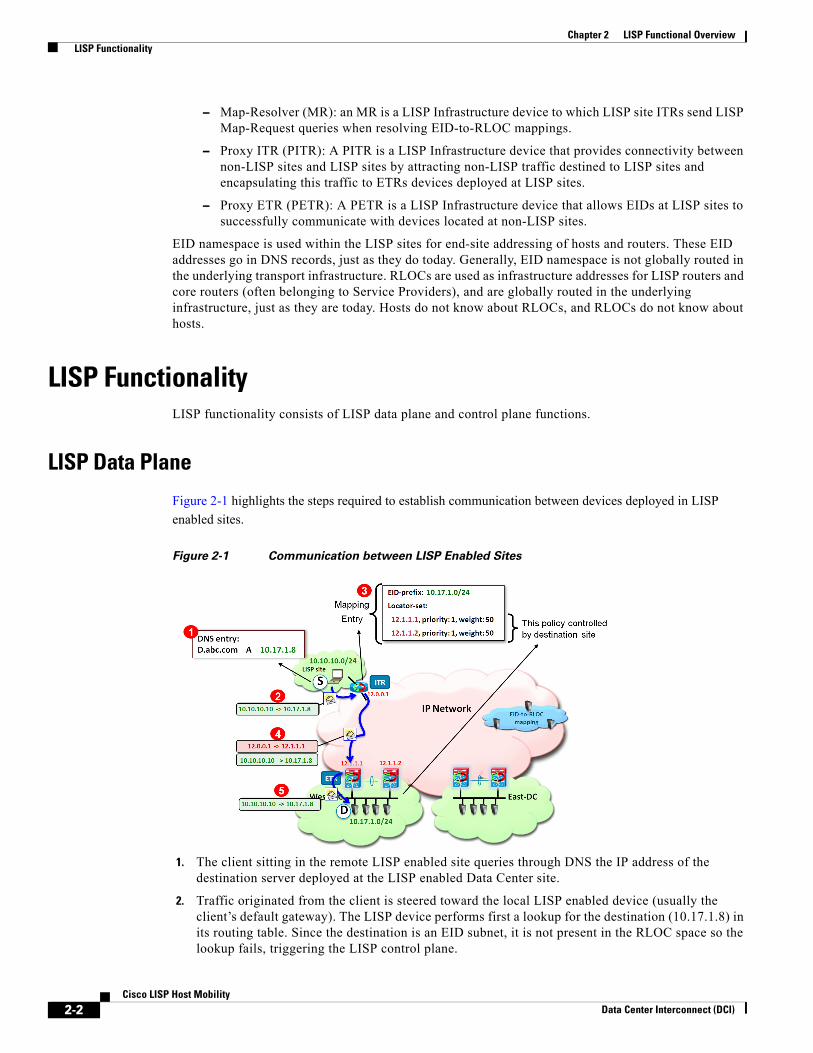
Figure 2-1 highlights the steps required to establish communication between devices deployed in LISP
enabled sites.
Figure 2-1 Communication between LISP Enabled Sites
1. The client sitting in the remote LISP enabled site queries through DNS the IP address of the destination server deployed at the LISP enabled Data Center site.
2. Traffic originated from the client is steered toward the local LISP enabled device (usually the client’s default gateway). The LISP device performs first a lookup for the destination (10.17.1.8) in its routing table. Since the destination is an EID subnet, it is not present in the RLOC space so the lookup fails, triggering the LISP control plane.
2-2Cisco LISP Host Mobility
Data Center Interconnect (DCI)

Chapter 2 LISP Functional Overview LISP Functionality
Note In the current IOS and NX-OS LISP implementation, the LISP control plane is triggered if the lookup for the destination address produces no results (no match) or if the only available match is a default route.
3. The ITR receives valid mapping information from the Mapping database and populates its local map-cache (the following “LISP Control Plane” section on page 2-4 will clarify the control plane communication required for this to happen). Notice how the destination EID subnet (10.17.1.0/24) is associated to the RLOCs identifying both ETR devices at the Data Center LISP enabled site. Also, each entry has associated priority and weights values that are controlled by the destination site to influence the way inbound traffic is received from the transport infrastructure. The priority is used to determine if both ETR devices can be used to receive LISP encapsulated traffic destined to a local EID subnet (load-balancing scenario). The weight allows tuning the amount of traffic received by each ETR in a load-balancing scenario (hence the weight configuration makes sense only when specifying equal priorities for the local ETRs).
4. On the data-plane, the ITR performs LISP encapsulation of the original IP traffic and send it into the transport infrastructure, destined to one of the RLOCs of the Data Center ETRs. Assuming the priority and weight values are configured the same on the ETR devices (as shown in Communication between LISP Enabled Sites1), the selection of the specific ETR RLOC is done on a per flow basis based on hashing performed on the 5-tuple L3 and L4 information of the original client’s IP packet. The format of a LISP encapsulated packet is shown in Figure 2-2.
Figure 2-2 Format of a LISP Encapsulated Packet
As shown in Figure 2-2, LISP leverages a UDP encapsulation where the src port value is dynamically created and associated to each original flow to ensure better load-balancing of traffic across the transport infrastructure.
5. The ETR receives the packet, decapsulates it and sends it into the site toward the destination EID.
While Figure 2-1 shows only the North-to-South flow, a similar mechanism would be used for the return traffic originated by the DC EID and destined to the remote client, where the LISP devices would exchange their roles of ITRs and ETRs.
Figure 2-3shows the use of PxTR devices to establish communication between devices deployed in non-LISP sites and EIDs available in LISP enabled sites.
2-3Cisco LISP Host Mobility
Data Center Interconnect (DCI)

Chapter 2 LISP Functional Overview LISP Functionality
Figure 2-3 Communication between non-LISP Enabled Sites and LISP Enabled Sites
Once the traffic reaches the PITR device, the mechanism used to send traffic to the EID in the Data Center is identical to what previously discussed. For this to work, it is mandatory that all the traffic originated from the non-LISP enabled sites be attracted to the PITR device. This is ensured by having the PITR injecting coarse-aggregate routing information for the Data Center EIDs into the network connecting to the non-LISP sites.
Note Detailed discussion on the deployment of a PxTR to provide services to non-LISP enabled location is out of the scope of this paper. Please reference the following document for more detailed PxTR configuration information: http://www.cisco.com/en/US/docs/solutions/Enterprise/Data_Center/DCI/whitepaper/PxTR_Redundancy/PxTR-Redundancy.pdf
LISP Control PlaneFigure 2-4 describes the steps required for an ITR to retrieve valid mapping information from the Mapping Database.
2-4Cisco LISP Host Mobility
Data Center Interconnect (DCI)

Chapter 2 LISP Functional Overview LISP Functionality
Figure 2-4 LISP Control Plane
1. The ETRs register with the MS the EID subnet(s) that are locally defined and which they are authoritative. In this example the EID subnet is 10.17.1.0/24. Map-registration messages are sent periodically every 60 seconds by each ETR.
2. Assuming that a local map-cache entry is not available, when a client wants to establish communication to a Data Center EID, a Map-Request is sent by the remote ITR to the Map-Resolver, which then forwards the message to the Map Server.
Note The Map Resolver and Map Server functionality can be enabled on the same device. More discussion about MS/MR deployment can be found in the “LISP Host Mobility Operation” section on page 3-5.
3. The Map Server forwards the original Map-Request to the ETR that last registered the EID subnet. In this example it is ETR with locator 12.1.1.2.
4. The ETR sends to the ITR a Map-Reply containing the requested mapping information.
5. The ITR installs the mapping information in its local map-cache, and starts encapsulating traffic toward the Data Center EID destination.
2-5Cisco LISP Host Mobility
Data Center Interconnect (DCI)

Chapter 2 LISP Functional Overview LISP Functionality
2-6Cisco LISP Host Mobility
Data Center Interconnect (DCI)