
LISA 19-DOF DRS Model - Pennsylvania State...
35
LISA LISA 19-DOF DRS Model Peiman Maghami and Tupper Hyde NASA GSFC Greenbelt, MD 20771 Fourth International LISA Symposium July 23, 2002
Transcript of LISA 19-DOF DRS Model - Pennsylvania State...
LISA
LISA 19-DOF DRS Model
Peiman Maghami and Tupper Hyde
NASA GSFC
Greenbelt, MD 20771
Fourth International LISA Symposium
July 23, 2002
LISA
Overview
• LISA dynamics and controls models aredeveloped to:� Evaluate LISA requirements and verify that they can
be met
� Evaluate DRS control architectures and strategies
� Perform trade studies
� Support the integrated modeling effort
• A 19 degrees of freedom model of a LISAspacecraft has been developed
LISA
LISA 19-DOF Model
LISA
Model Overview
• Full LISA S/C model: S/C (6 DOF), two ProofMasses (6 DOF each), and telescope articulation
• Nonlinear translational and rotational kinematicsand dynamics
• Preliminary designs for the four main controlsystems: Drag-Free control, Attitude control,Proof Mass suspension control, and telescopearticulation control
• A decentralized approach to control is followed
• Realistic LISA orbits are brought in via ephemerisfile: obtained from orbit design and optimization
LISA
Model Overview (Cont’d)
• Orbital ephemeris are also used to simulate incoming laserbeam directions for S/C attitude control and telescopearticulation control
• Point-ahead angle dynamics and its compensation are notconsidered
• Measurement and actuation noise models are included
• Approximations to nonlinear electrostatic forces andtorques, as well as, those from self-gravity, are included
• Realistic gravity gradient forces (due to the Sun) and Solarradiation pressure forces/torques (bias and variations) areincluded
LISA
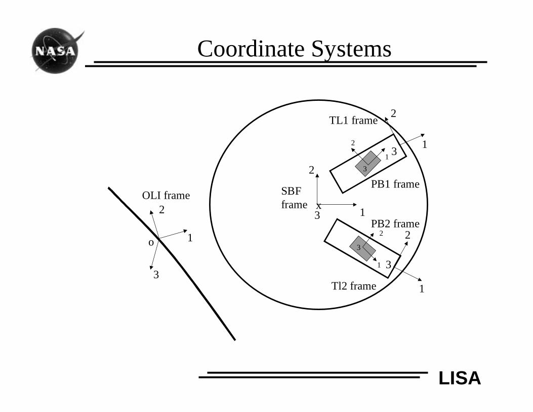
Coordinate Systems
x
o 1
2
3
OLI frame
1
2
3
SBFframe
1
2
3
TL1 frame
1
2
3
Tl2 frame
1
2
3
1
2
3
PB1 frame
PB2 frame
LISA
Measurement and Actuation Models
• Model assumes that laser detector measurements provideunit vectors along the paths of the incoming laser beams.
• Detector noise model is included for S/C attitude controland telescope articulation control.
• Relative PM-S/C attitude and translation (GRS):• Noise models for sensing and actuation included.
• Actuation forces and torques are applied in the proof mass housingframe.
• Nonlinear electrostatic forces and torques, as well as, those fromself-gravity, are modeled via a linear time-invariant system.
• Actuation and sensing cross-talk is included.
• µN-thruster noise model is included.
• Actuator quantization for telescope articulation is included
LISA
Disturbance Reduction System Control
• DRS control comprises five control systems• S/C attitude control system (ACS): to orient the S/C to align the
telescopes with incoming laser beams
• Drag free control system (DFC): to maintain drag free motion ofthe proof masses in LISA measurement directions
• Proof mass (PM) suspension control: to maintain relative attitudeof the proof mass with respect to its housing an to maintain relativeposition of the proof mass with respect to its housing in thetransverse directions
• Telescope articulation (TA) control: to maintain the angle betweenthe telescopes
• Point ahead (PA) and acquisition control: to point the outgoingbeam while sensing the incoming beam using communication fromthe other spacecraft
LISA
S/C Attitude Control System
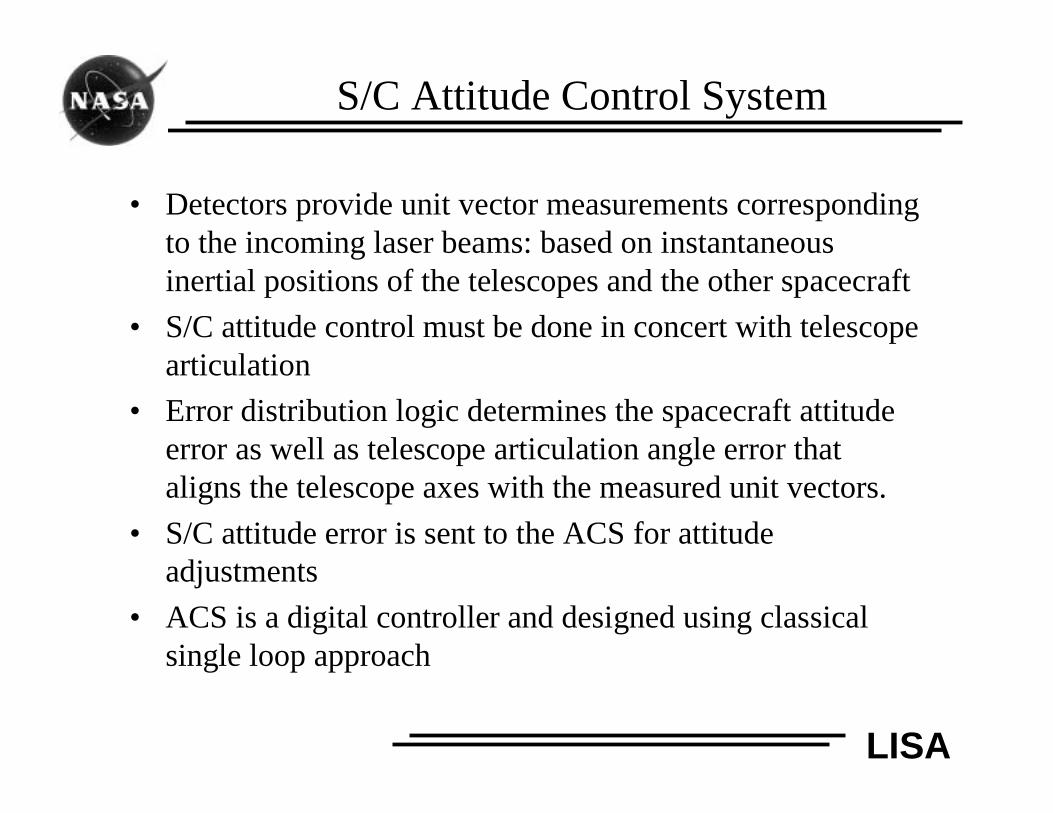
• Detectors provide unit vector measurements correspondingto the incoming laser beams: based on instantaneousinertial positions of the telescopes and the other spacecraft
• S/C attitude control must be done in concert with telescopearticulation
• Error distribution logic determines the spacecraft attitudeerror as well as telescope articulation angle error thataligns the telescope axes with the measured unit vectors.
• S/C attitude error is sent to the ACS for attitudeadjustments
• ACS is a digital controller and designed using classicalsingle loop approach
LISA
Telescope Articulation Control
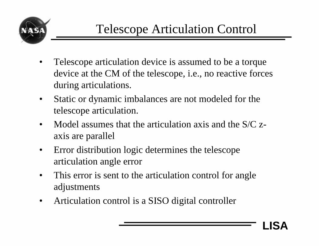
• Telescope articulation device is assumed to be a torquedevice at the CM of the telescope, i.e., no reactive forcesduring articulations.
• Static or dynamic imbalances are not modeled for thetelescope articulation.
• Model assumes that the articulation axis and the S/C z-axis are parallel
• Error distribution logic determines the telescopearticulation angle error
• This error is sent to the articulation control for angleadjustments
• Articulation control is a SISO digital controller
LISA
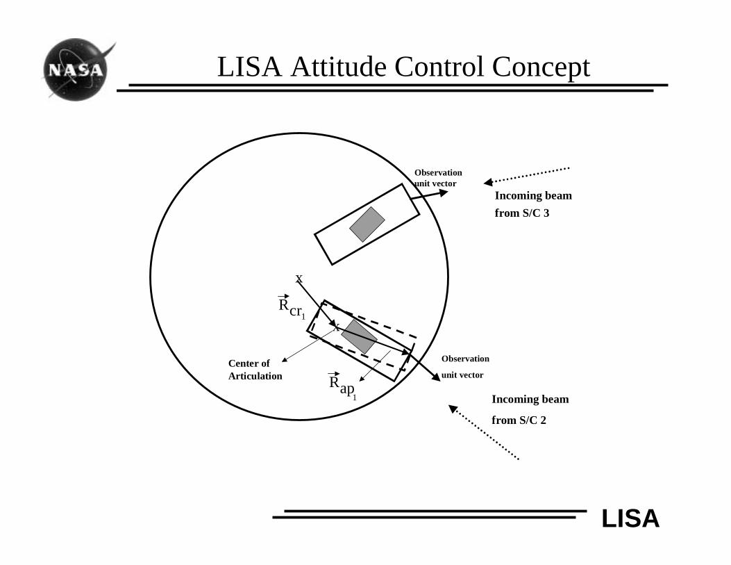
LISA Attitude Control Concept
x
Incoming beam
from S/C 3
Incoming beam
from S/C 2
Observationunit vector
Observation
unit vector
x
Rap1
Rcr1
Center ofArticulation
LISA
Attitude and Articulation Errors
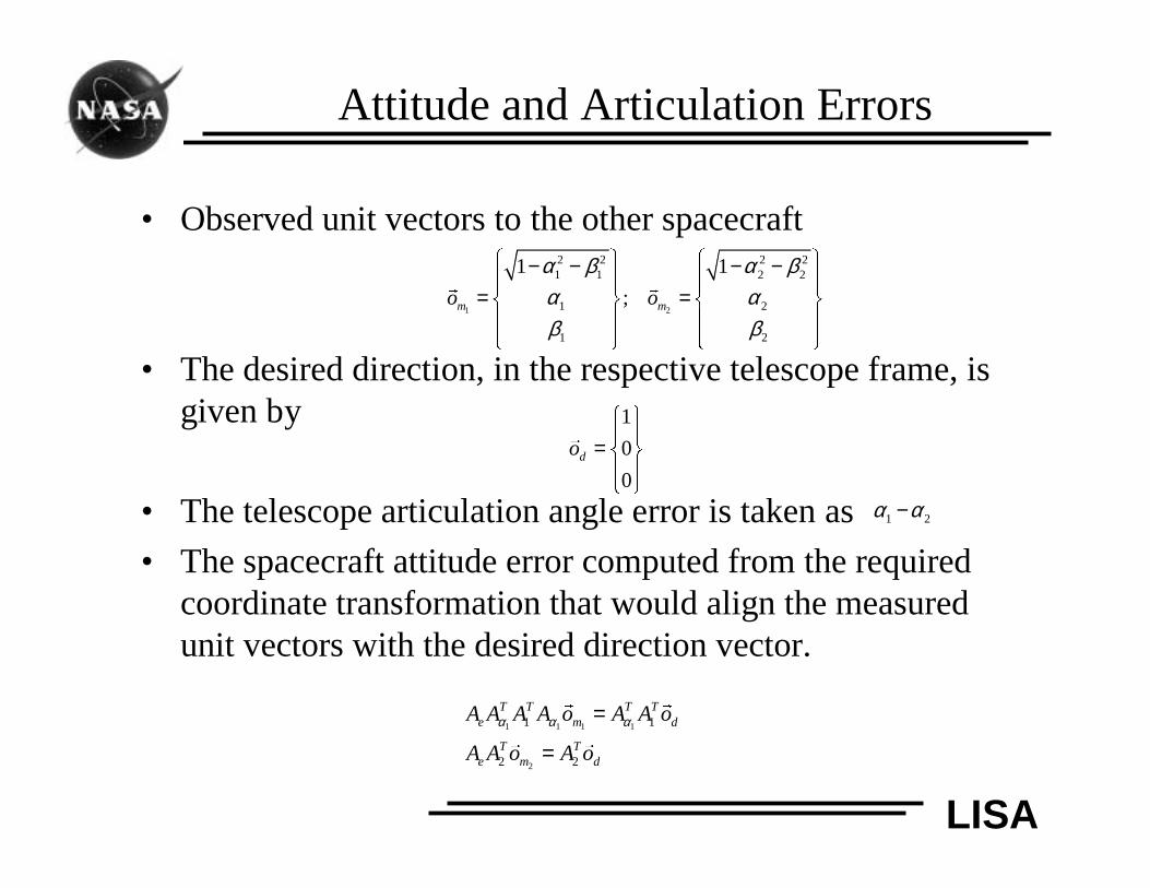
• Observed unit vectors to the other spacecraft
• The desired direction, in the respective telescope frame, isgiven by
• The telescope articulation angle error is taken as
• The spacecraft attitude error computed from the requiredcoordinate transformation that would align the measuredunit vectors with the desired direction vector.
1 2
2 2 2 21 1 2 2
1 2
1 2
1 1
;m mo o
α β α βα αβ β
− − − − = =
� �
1
0
0do
=
�
1 2α α−
1 1 1 1
2
1 1
2 2
T T T Te m d
T Te m d
A A A A o A A o
A A o A o
α α α=
=
� �
� �
LISA
Proof Mass Attitude Control
• Uses relative attitude of the proof mass with respect to itshousing from capacitive sensing
• Suspension torques are applied at the housing frame
• The relative attitude error is sent to the suspension controlfor proof mass attitude adjustments
• The attitude suspension controller is a digital controllerdesigned using classical single loop approach
LISA
Drag Free Control
• The relative position of the center of mass of the proofmass from its housing is measured by capacitive sensing.
• Two strategies are considered for drag free control:
� Both strategies do not allow proof mass translationcontrol in the sensitive (measurement) axes (FTRStrategy 4): S/C translation will have to center the proofmasses in these directions
� First strategy permits commanding of the gravitationalsensors (in the transverse directions) in a centralizedmanner: cross coupling between sensors
� Second strategy does not allow for centralizedcommanding of the gravitational sensors : proof masssimply follows the housing (no coupling)
LISA
Drag Free Control (cont’d)
• The out-of-plane DOF of the 2nd proof mass is notsuspended in both strategies: S/C translation will take careof it
• Error distribution matrix computes position errors for theS/C and the proof masses (in the transverse direction) toachieve drag-free motion in the measurement axes as wellas to center the proof masses in the transverse directions
• S/C position error is sent to the Drag-free control for S/Ctranslational adjustments
• Proof mass position error is sent to the translationalsuspension control for position adjustments
• Both DFC and suspension controllers are designed basedon digital classical single loop designs.
LISA
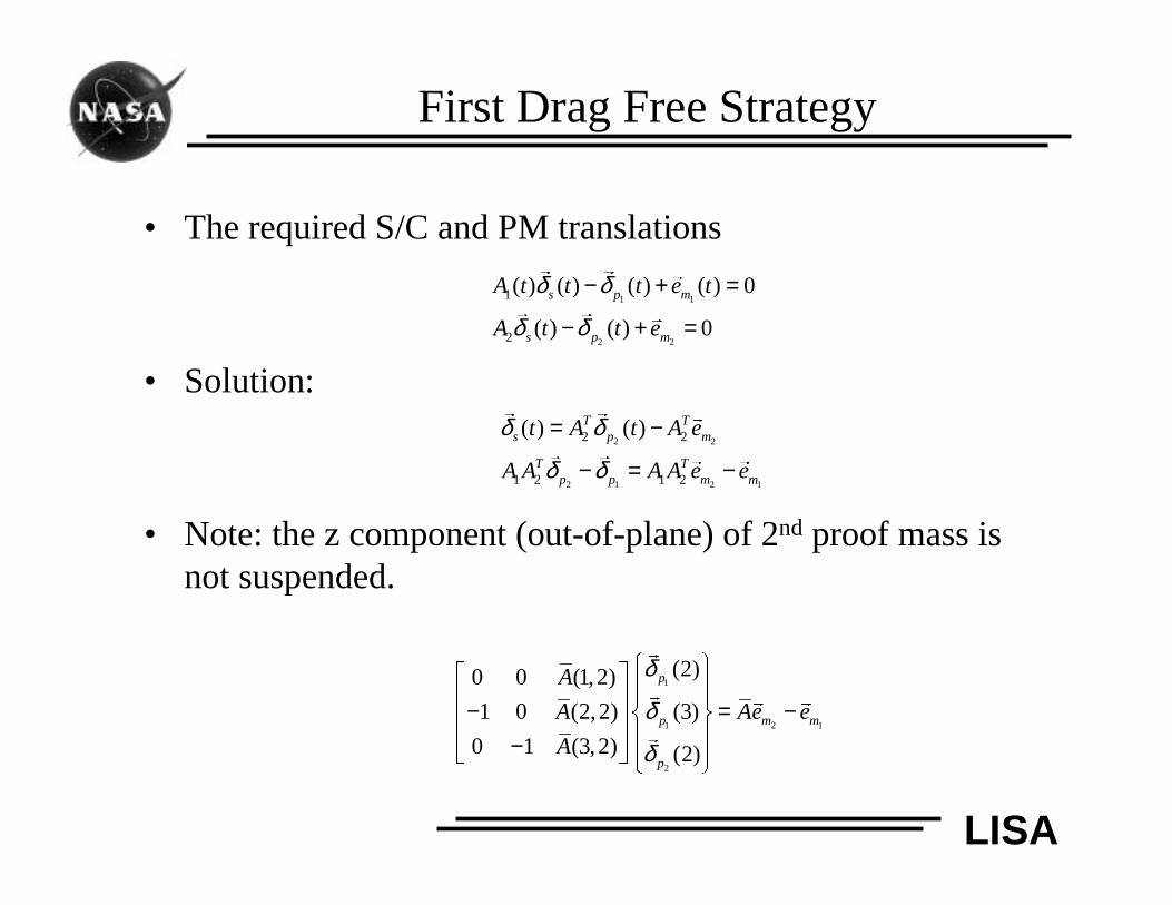
First Drag Free Strategy
• The required S/C and PM translations
• Solution:
• Note: the z component (out-of-plane) of 2nd proof mass isnot suspended.
1 1
2 2
1
2
( ) ( ) ( ) ( ) 0
( ) ( ) 0
s p m
s p m
A t t t e t
A t t e
δ δ
δ δ
− + =
− + =
� �
�
� �
�
2 2
2 1 2 1
2 2
1 2 1 2
( ) ( )T Ts p m
T Tp p m m
t A t A e
A A A A e e
δ δ
δ δ
= −
− = −
� �
�
� �
� �
1
1 2 1
2
(2)0 0 (1,2)
1 0 (2,2) (3)
0 1 (3,2) (2)
p
p m m
p
A
A Ae e
A
δ
δ
δ
− = − −
�
�
� �
�
LISA
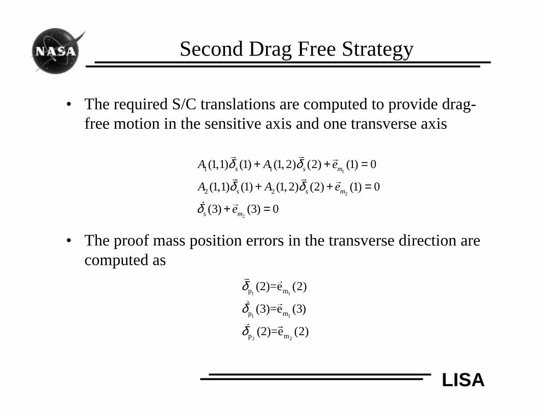
Second Drag Free Strategy
• The required S/C translations are computed to provide drag-free motion in the sensitive axis and one transverse axis
• The proof mass position errors in the transverse direction arecomputed as
1
2
2
1 1
2 2
(1,1) (1) (1, 2) (2) (1) 0
(1,1) (1) (1, 2) (2) (1) 0
(3) (3) 0
s s m
s s m
s m
A A e
A A e
e
δ δ
δ δ
δ
+ + =
+ + =
+ =
� �
�
� �
�
�
�
1 1
1 1
2 2
p m
p m
p m
(2)=e (2)
(3)=e (3)
(2)=e (2)
δ
δ
δ
�
�
�
�
�
�
LISA
LISA Simulation Model
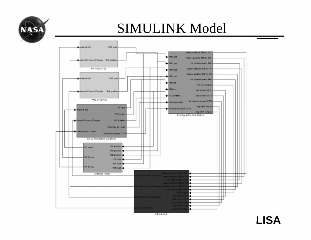
• Model is developed in SIMULINK environmentwith MATLAB script file driver• Different stiff and non-stiff solvers are available for integration
• Hybrid systems and nonlinearities are fully treated
• Orbital ephemeris (obtained from optimization) areimported
• Realistic initial attitudes and rates (S/C & PMs) obtainedfrom ephemeris data
LISA
SIMULINK Model
LISA
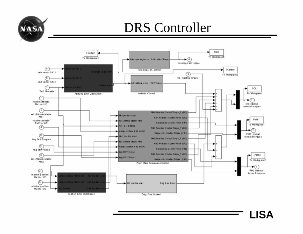
DRS Controller
LISA
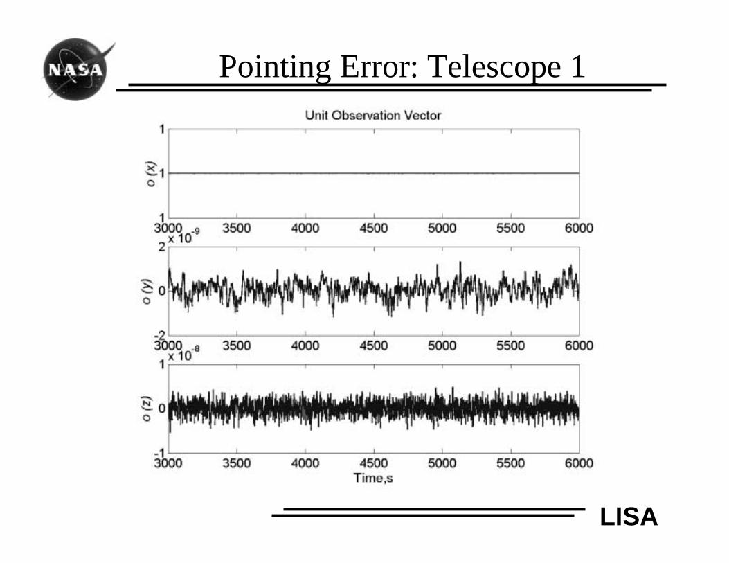
Pointing Error: Telescope 1
LISA
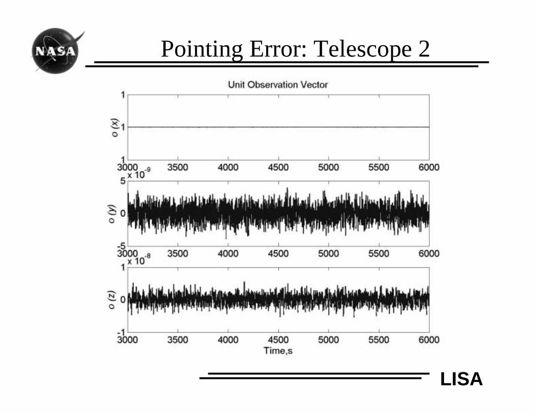
Pointing Error: Telescope 2
LISA
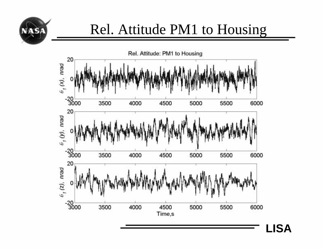
Rel. Attitude PM1 to Housing
LISA
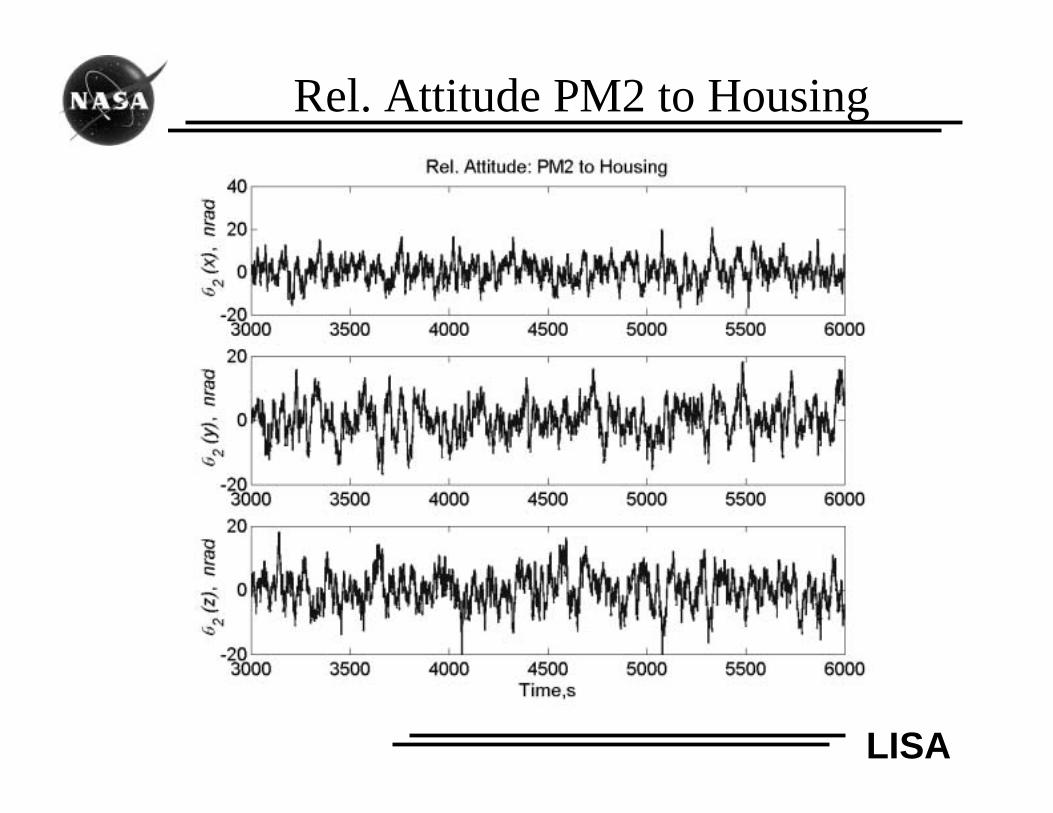
Rel. Attitude PM2 to Housing
LISA
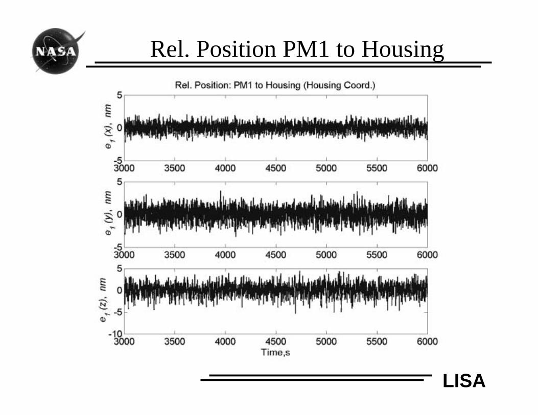
Rel. Position PM1 to Housing
LISA
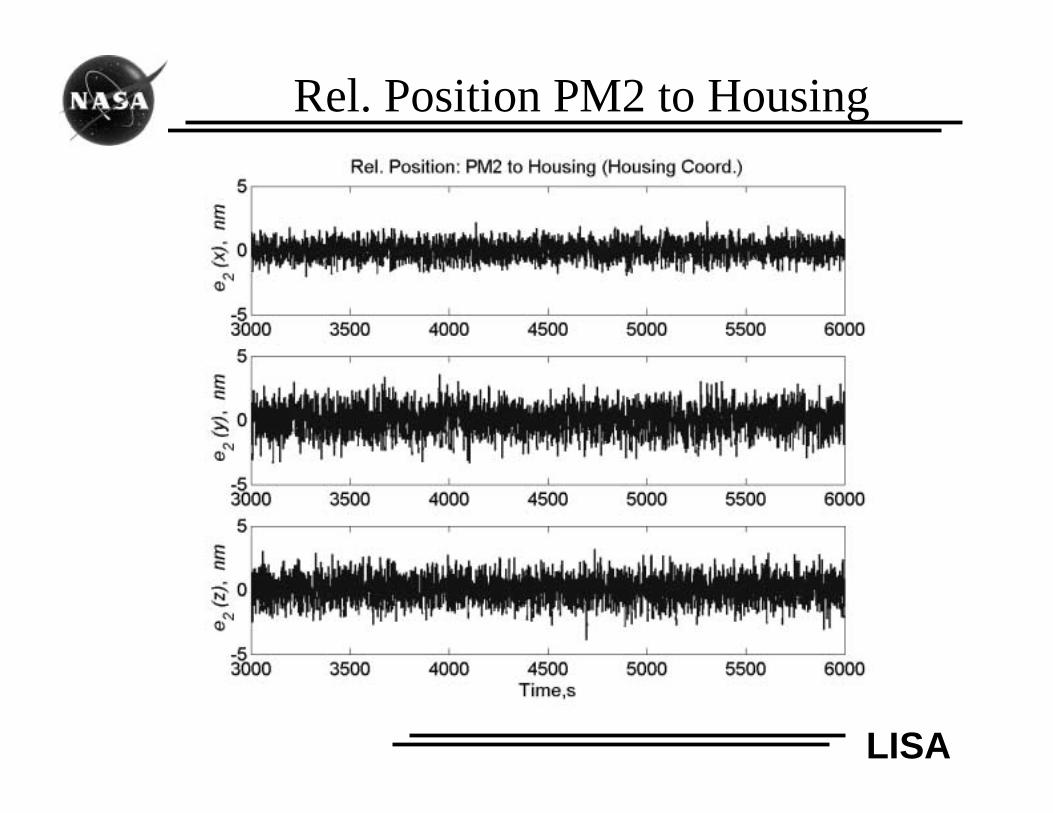
Rel. Position PM2 to Housing
LISA
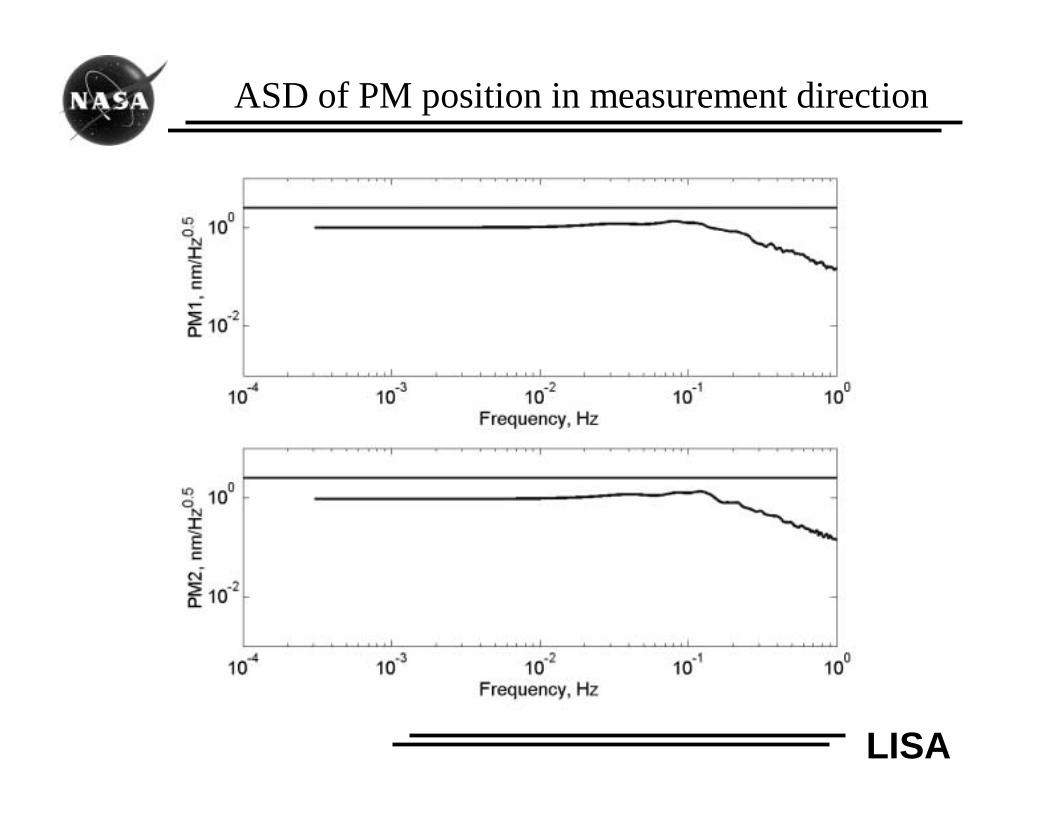
ASD of PM position in measurement direction
LISA
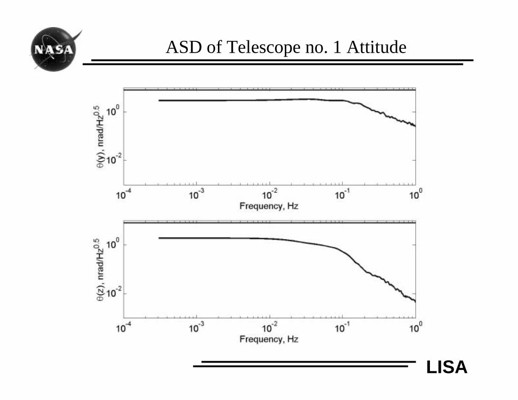
ASD of Telescope no. 1 Attitude
LISA
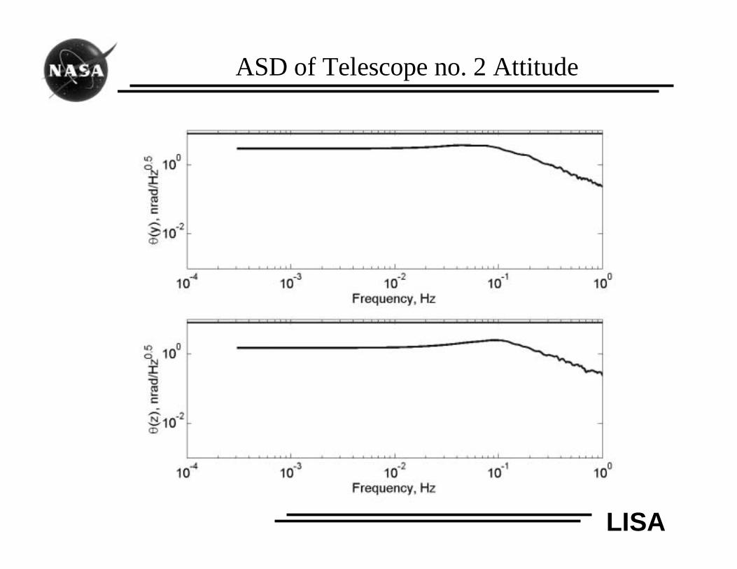
ASD of Telescope no. 2 Attitude
LISA
Future Work
• Obtain a linear 19-DOF model• Frequency-domain analysis
• Robustness and stability analysis
• Perform trade studies on DRS control• Control strategies and architecture
• MIMO and robust control designs
• Integrated modeling and analysis• Couple DRS simulation with optics
• Investigate point-ahead and acquisition controls
• Improve model fidelity
• Develop a full 57 DOF LISA formation model
LISA
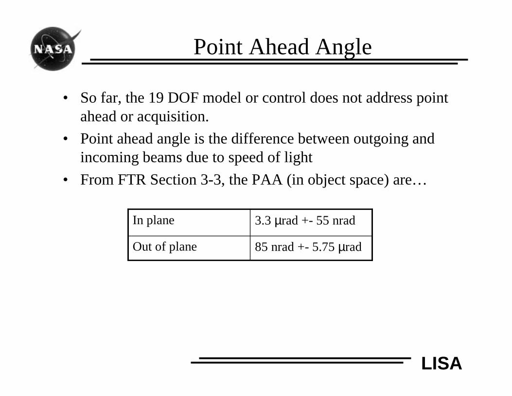
Point Ahead Angle
• So far, the 19 DOF model or control does not address pointahead or acquisition.
• Point ahead angle is the difference between outgoing andincoming beams due to speed of light
• From FTR Section 3-3, the PAA (in object space) are…
85 nrad +- 5.75 µradOut of plane
3.3 µrad +- 55 nradIn plane
LISA
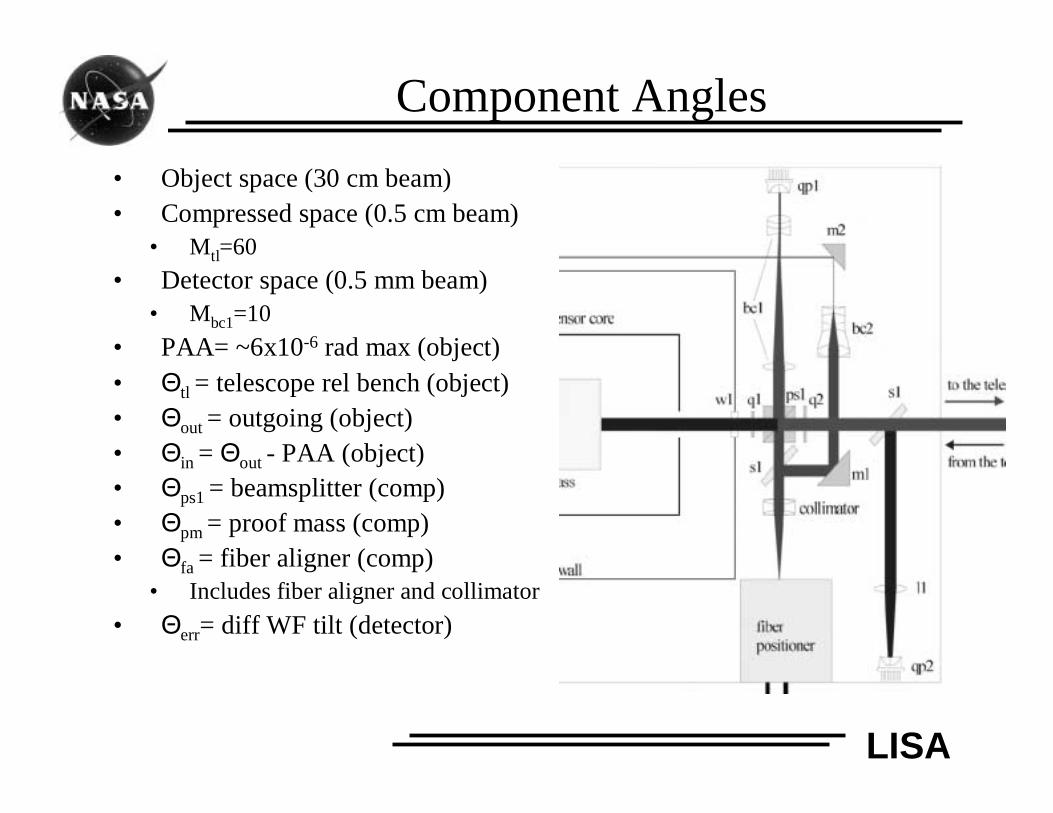
Component Angles
• Object space (30 cm beam)• Compressed space (0.5 cm beam)
• Mtl=60
• Detector space (0.5 mm beam)• Mbc1=10
• PAA= ~6x10⁻⁶ rad max (object)• Θtl = telescope rel bench (object)• Θout = outgoing (object)• Θin = Θout - PAA (object)• Θps1 = beamsplitter (comp)• Θpm = proof mass (comp)• Θfa = fiber aligner (comp)
• Includes fiber aligner and collimator
• Θerr= diff WF tilt (detector)
LISA
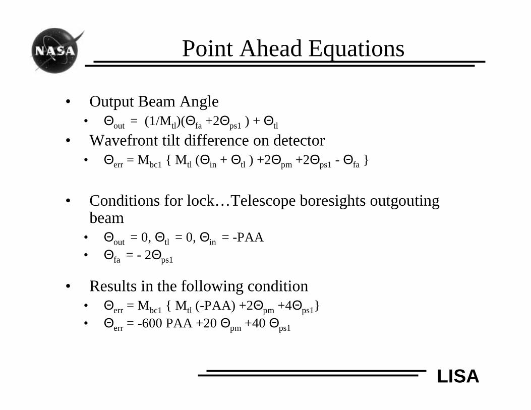
Point Ahead Equations
• Output Beam Angle• Θout = (1/Mtl)(Θfa +2Θps1 ) + Θtl
• Wavefront tilt difference on detector• Θerr = Mbc1 { Mtl (Θin + Θtl ) +2Θpm +2Θps1 - Θfa }
• Conditions for lock…Telescope boresights outgoutingbeam
• Θout = 0, Θtl = 0, Θin = -PAA• Θfa = - 2Θps1
• Results in the following condition• Θerr = Mbc1 { Mtl (-PAA) +2Θpm +4Θps1}• Θerr = -600 PAA +20 Θpm +40 Θps1
LISA
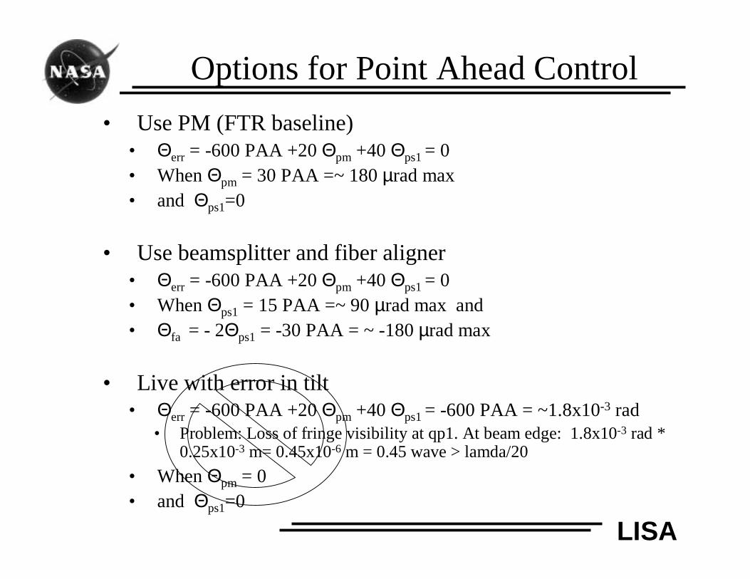
Options for Point Ahead Control
• Use PM (FTR baseline)• Θerr = -600 PAA +20 Θpm +40 Θps1 = 0• When Θpm = 30 PAA =~ 180 µrad max• and Θps1=0
• Use beamsplitter and fiber aligner• Θerr = -600 PAA +20 Θpm +40 Θps1 = 0• When Θps1 = 15 PAA =~ 90 µrad max and• Θfa = - 2Θps1 = -30 PAA = ~ -180 µrad max
• Live with error in tilt• Θerr = -600 PAA +20 Θpm +40 Θps1 = -600 PAA = ~1.8x10⁻³ rad
• Problem: Loss of fringe visibility at qp1. At beam edge: 1.8x10-3 rad *0.25x10-3 m= 0.45x10⁻⁶ m = 0.45 wave > lamda/20
• When Θpm = 0• and Θps1=0
LISA
Summary
• Conclusion:• Steering proof mass remains baseline for now
• requires ~ 180 microradians max, what are implications forcalibrations at other than “zero”
• To do:• Use real optics math
• Include other downstream optics (cavity, backside, etc.) andbeam walk.
• Look at acquisition and calibration
• Look at mechanisms for beamsplitter and fiber aligner