Liquid Salt Test Loop Operations - Oak Ridge National … · · 2017-04-13and Development (LDRD)...
36
ORNL is managed by UT-Battelle for the US Department of Energy Liquid Salt Test Loop Operations D. K. Felde E. Dominguez-Ontiveros D. Fugate D. Holcomb K. R. Robb G. L. Yoder, Jr. Second Molten Salt Reactor Workshop October 4–5, 2016
Transcript of Liquid Salt Test Loop Operations - Oak Ridge National … · · 2017-04-13and Development (LDRD)...
ORNL is managed by UT-Battelle for the US Department of Energy
Liquid Salt Test Loop Operations
D. K. Felde
E. Dominguez-Ontiveros
D. Fugate
D. Holcomb
K. R. Robb
G. L. Yoder, Jr.
Second Molten Salt Reactor Workshop October 4–5, 2016

2 Liquid Salt Test Loop Operations
Outline
• Project goals • System description and capabilities • Key facility components completed over the last year • Facility operations • Summary

3 Liquid Salt Test Loop Operations
Project History
• 2009–2010: Initial funding support through the Oak Ridge National Laboratory (ORNL) Laboratory Directed Research and Development (LDRD) program
• 2011–2013: Follow-on DOE support to add salt clean-up capability and instrumentation
• 2015–2016: Funding from the Shanghai Institute of Applied Physics (SINAP) to complete loop and perform initial testing

4 Liquid Salt Test Loop Operations
Project goals are to develop a new experimental facility that will: 1. Provide infrastructure (operational
knowledge and equipment) to test high-temperature salt systems
2. Develop a nonintrusive, inductive heating technique that can be used for thermal/fluid experimentation, and provide pebble heating that is prototypic of nuclear fuel (volumetric)
3. Measure heat transfer characteristics in a molten salt cooled pebble bed
4. Demonstrate SiC as a structural material for use in molten salt systems (joining and compatibility, including interest as a high-temperature structural component)

5 Liquid Salt Test Loop Operations
The Liquid Fluoride Salt Test Loop is designed to provide relevant data for molten salt reactor development • Loop specifications are as follows
Salt FLiNaK
Operating temperature up to 700 °C
Flow rate 4.5 kg/s
Operating pressure atmospheric
Material of construction Inconel 600
Loop volume 72 liters
• Initial testing is focused on PB-AHTR pebble heat transfer
PB-AHTR Experiment
Coolant FLiBe FLiNaK
Bed diameter (cm) 20 15
Bed height (m) 3.2 0.75
Pebble dia.(cm) 3 3
Pebble Re 3,080 2,570
Pebble arrangement random random
ORNL Liquid Salt Test Loop

6 Liquid Salt Test Loop Operations
The forced convection loop incorporates inductively heated pebble test section • Storage tank: Long term salt storage allows re-
solidification
• Pump sump – Always liquid – Sump type centrifugal pump
• SiC test section (pebble channel): ~450 graphite pebbles (middle ~⅓ heated); ~1,250 W/pebble (peak)
• 200 kW inductive heating
• Forced draft air cooler
• Trace heating system
• Major measurements – FLiNaK temperatures – Pebble temperatures – Inductive power input – Pump discharge pressure – Gas space pressures – FLiNaK flow rate

7 Liquid Salt Test Loop Operations
Key facility components completed in the last year, leading to facility startup • Completion of instrumentation and controls for the purification and loop systems
– Thermal management system completed for 25 heater zones – Remote operation and checkout of pump, fans, and induction power supply – Sensors added for HF and hydrogen gas detection – Accelerometers added to record pump vibration
• Modification of the test section upper flange: Offline tests on SiC test section mock-ups completed to characterize bolting torque and seal alignment/gap requirements
• Installation of SiC test section: 450 graphite pebbles and 7 thermocouples installed in the test section
• Modification of the scrubber system for HF capture on crucible exhaust line: HF and hydrogen gas hazards mitigated with innovative design

8 Liquid Salt Test Loop Operations
100+ thermocouples used to monitor and control loop and test section temperature
• Pink boxes indicate temperature location (°C) • 1296 indicates disconnected thermocouple
• PT yellow boxes indicate pressure (psig and salt head) • *Flow meter is not installed • Values indicative of loop pre-operation

9 Liquid Salt Test Loop Operations
Thermal management system worked very well
• Only a few issues were encountered during initial heat up and shakedown of the system: – Heater blanket on the crucible required
additional insulating layer between blanket and vessel wall to eliminate electrical shorting problem at high temperature
– Careful selection of the ground fault circuit breakers needed on some heater zones to prevent leakage current tripping, particularly on Calrod®-type heaters used on vessel bottoms
Cleanup Vessel Insulation and Heater Blanket
10 Liquid Salt Test Loop Operations
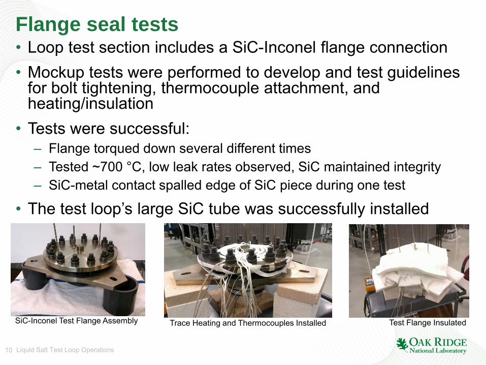
Flange seal tests • Loop test section includes a SiC-Inconel flange connection • Mockup tests were performed to develop and test guidelines
for bolt tightening, thermocouple attachment, and heating/insulation
• Tests were successful: – Flange torqued down several different times – Tested ~700 °C, low leak rates observed, SiC maintained integrity – SiC-metal contact spalled edge of SiC piece during one test
• The test loop’s large SiC tube was successfully installed
SiC-Inconel Test Flange Assembly Trace Heating and Thermocouples Installed Test Flange Insulated
11 Liquid Salt Test Loop Operations
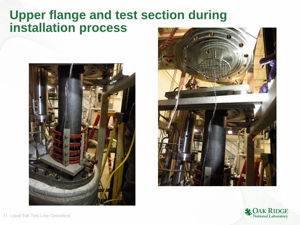
Upper flange and test section during installation process

12 Liquid Salt Test Loop Operations
Thermocouples are installed during installation of 450 graphite pebbles
Two fluid and two pebble thermocouples are installed at the axial center of the test section
A fluid thermocouple is wrapped around the lower screen before pebble installation
13 Liquid Salt Test Loop Operations
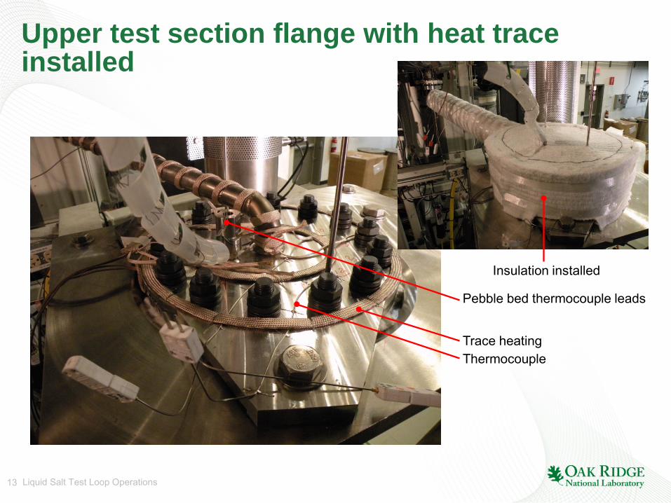
Upper test section flange with heat trace installed
Trace heating Thermocouple
Pebble bed thermocouple leads
Insulation installed

14 Liquid Salt Test Loop Operations
Test section has heater tape installed inside induction power coil for system heat up
15 Liquid Salt Test Loop Operations
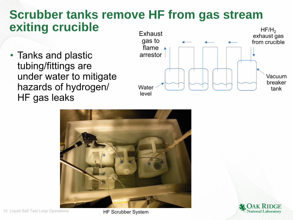
Scrubber tanks remove HF from gas stream exiting crucible
• Tanks and plastic tubing/fittings are under water to mitigate hazards of hydrogen/ HF gas leaks
HF/H2 exhaust gas from crucible
Exhaust gas to flame
arrestor
Water level
Vacuum breaker
tank
HF Scrubber System

16 Liquid Salt Test Loop Operations
Planned sequence for facility operations
1. Salt purification in crucible to remove oxygen, moisture and other contaminants
2. Hydrogen firing of storage tank (4% H2, 96% Ar) during initial heat up
3. Transfer salt from crucible to loop storage tank
4. Hydrogen firing of loop system during initial heat up
5. Fill loop with salt (via transfer tube from storage tank)
6. Operate pump and flow salt through loop (clean loop)
7. Verify operation of pebble bed induction power supply and coil
8. Transfer salt back to crucible for cleanup
9. Transfer salt back to loop for heat transfer tests
10. Perform heat transfer tests

17 Liquid Salt Test Loop Operations
Salt purification is a multi-day process: 1. Load the crucible with (dry) constituent
fluoride salts (LiF, NaF, KF)
2. Heat up and melt salt components in the crucible under an inert Ar atmosphere
3. Sparge molten salt with HF and hydrogen gas for three days
4. Sparge molten salt with hydrogen gas for one day
5. Purge molten salt and crucible system with Ar gas for approximately one day
6. Install transfer tube between crucible and storage tank
7. Transfer salt to storage tank through a 25 micron filter
160 kg of salt loaded into crucible; bubbler gas line and thermocouple array probe extend to near the bottom of the vessel
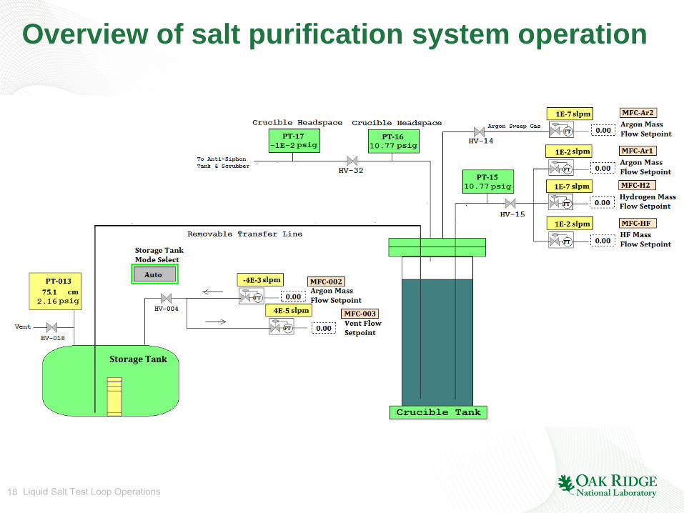
18 Liquid Salt Test Loop Operations
Overview of salt purification system operation

19 Liquid Salt Test Loop Operations
First salt purification process worked well, with the exception of a couple of issues: • Apparent failure of HF gas mass flow controller after ~5 h
of sparging – Determined that HF gas condensed in the mass flow controller,
blocking gas flow – Added trace heating and insulation to mass flow controller in
HF cabinet
• Plugging of flame arrestor on exhaust gas line from scrubber tanks – Installed a parallel array of three flame arrestors – Ensured that they could be valved in as needed

20 Liquid Salt Test Loop Operations
• Salt transfer completed April 11, 2016
Transfer tube installed between crucible and storage tank
25 micron filter
Transfer line
25 micron basket-type filter after transfer

21 Liquid Salt Test Loop Operations
Initial heat up of loop showed that some regions required additional heater power and/or insulation • Higher power Calrod® heaters required
on heat exchanger faces
• Additional insulation required on exchanger edges to reach acceptable temperature
• Heat trace and insulation added to outside of ultrasonic flow meter to increase pipe temperature (electronics removed from flow meter).

22 Liquid Salt Test Loop Operations
• Unable to heat pipe sufficiently with trace heating (insulation removed for photo)
• Heaters were added outside flow meter (with electronics removed) for loop salt operations
• Cartridge heaters planned for installation on pipe near flow meter for future testing
Flexim ultrasonic flow meter installed on pipe
Flow Meter Waveguides Installed

23 Liquid Salt Test Loop Operations
Successful loop heat up

24 Liquid Salt Test Loop Operations
Display snapshot prior to transferring salt into loop indicating temperature levels (°C)
• Pink boxes indicate temperature location (°C) • PT yellow boxes indicate pressure (psig and salt head) • *Flow meter is not installed

25 Liquid Salt Test Loop Operations
Argon gas used for salt transfer and level control
Argon Cover Gas Controllers
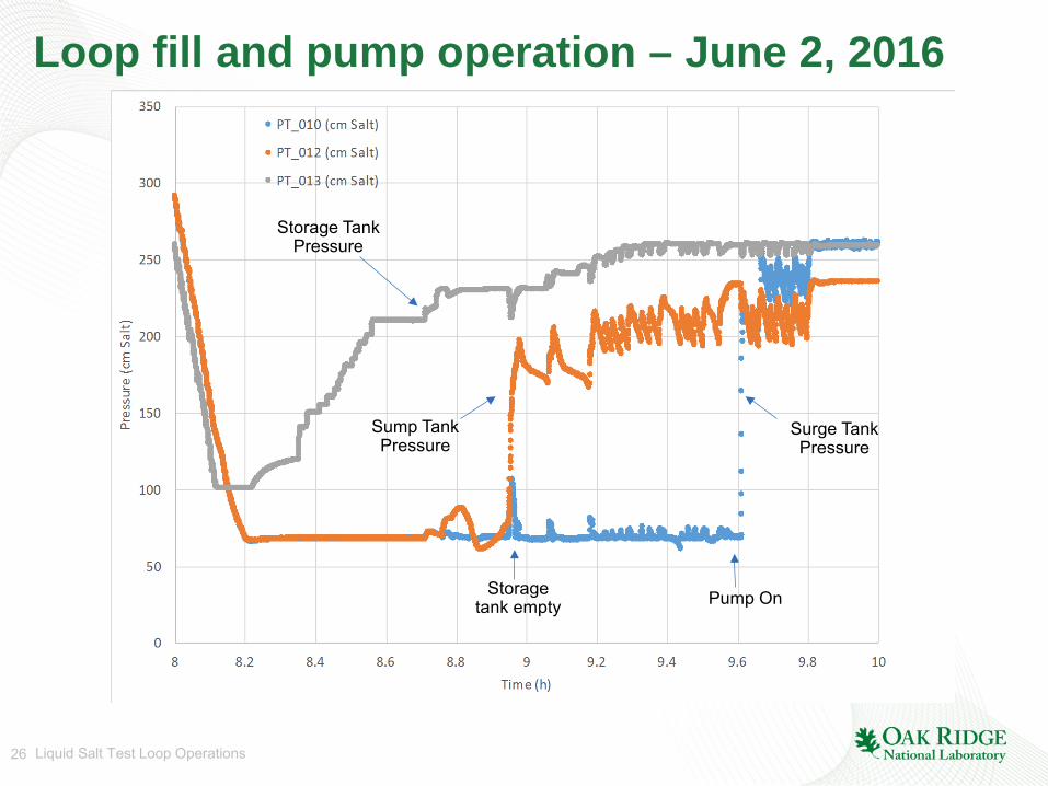
26 Liquid Salt Test Loop Operations
Loop fill and pump operation – June 2, 2016
Storage tank empty Pump On
Storage Tank Pressure
Surge Tank Pressure
Sump Tank Pressure

27 Liquid Salt Test Loop Operations
Remaining steps
1. Modify ultrasonic flow meter heater/insulation configuration to allow operation at temperature
a. Attach cartridge heaters to pipe b. Insulate pipe and heaters c. Cool waveguide/electronics interface
2. Modify insulation on heat exchanger and install ductwork to complete air cooling circuit
3. Transfer salt from storage tank to crucible and re-purify 4. Transfer salt back to storage tank/loop and perform heat
transfer testing

28 Liquid Salt Test Loop Operations
Summary • Purified 160 kg of FLiNaK salt • Loop operations conducted at ~650 °C salt temperature • Pump operation conducted at high temperature • Demonstrated capability of transferring salt from storage
tank to loop and back while controlling salt level • Induction power supply operation to heat pebbles • Salt currently maintained under an inert atmosphere in
storage tank • Facility now commissioned and prepared for forced
convection testing • Awaiting funding to complete salt re-purification and perform
heat transfer tests

29 Liquid Salt Test Loop Operations
Backup slides

30 Liquid Salt Test Loop Operations
Salt Clean-up Process: removal of moisture and oxygen from commercial salt necessary to reduce corrosion of typical engineering materials
• Based on the clean-up process developed for the Molten Salt Reactor Experiment (MSRE) 1. Heat salt powder from room temperature to ~300 °C
to drive off moisture (3 l/m Ar sparge, 3 l/m Ar sweep) 2. Melt salt 300 °C to 600 °C (3 l/m Ar) 3. H2/HF sparge removes oxygen/water from salt
(300 ml/m HF, 3 l/m H2) ~ 600 °C • O2 + 4HF ↔ 4F- + 2H2O • 2M0 + 6HF ↔ 2MF3 + 3H2
4. H2 sparge to remove metal fluoride impurities 5. Ar sweep to remove HF and H2 from system ~600 °C

31 Liquid Salt Test Loop Operations
Heater zone power • Controlled using proportional–integral–derivative (PID)
feedback from thermocouple input with software-controlled output function
• Heater power output varied using solid state relays to turn heater power off or on – A control thermocouple from each heater zone is used as input to a
PID feedback loop – Output of the PID controls percentage of time that heater is on over a
10 s period to maintain the target temperature – A second monitoring thermocouple is used for each zone to provide
additional temperature indication, including interlock protection – A ramp/soak function can be used to ramp temperatures or follow a
desired temperature profile
• Cost effective: adding heater zone only requires solid-state relay, circuit breaker and the PLC input/output.
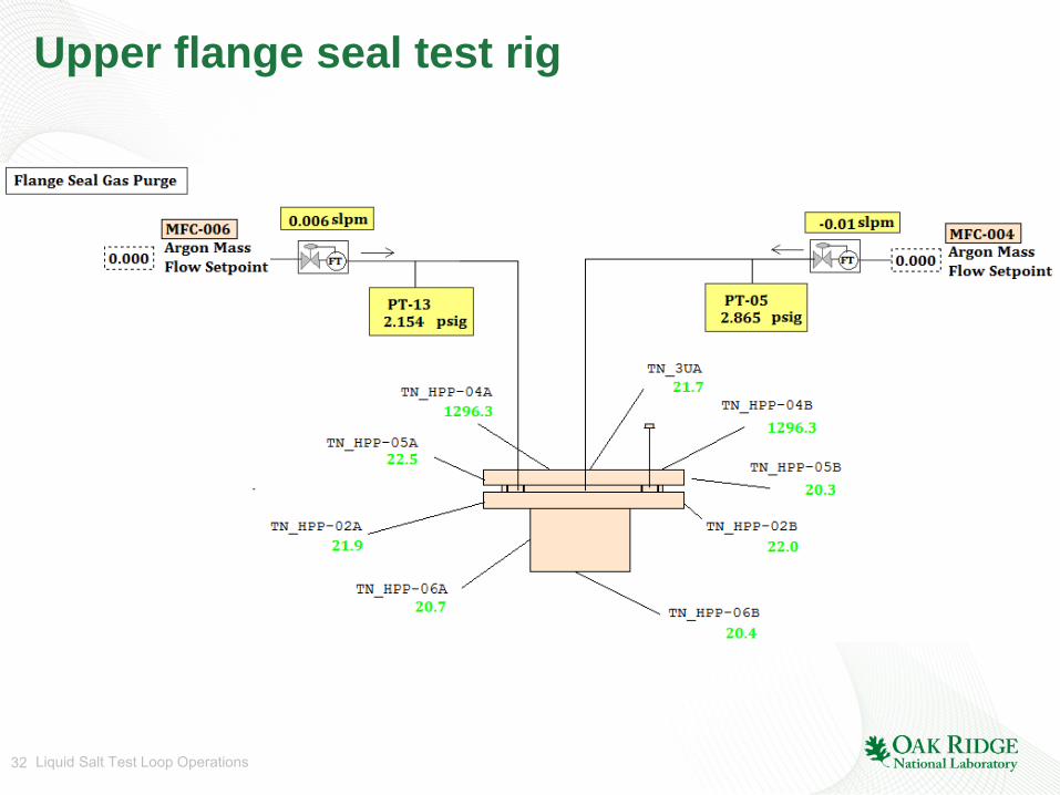
32 Liquid Salt Test Loop Operations
Upper flange seal test rig
33 Liquid Salt Test Loop Operations
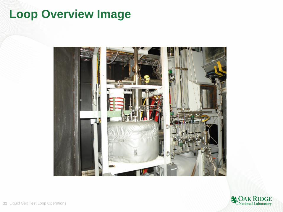
Loop Overview Image
34 Liquid Salt Test Loop Operations
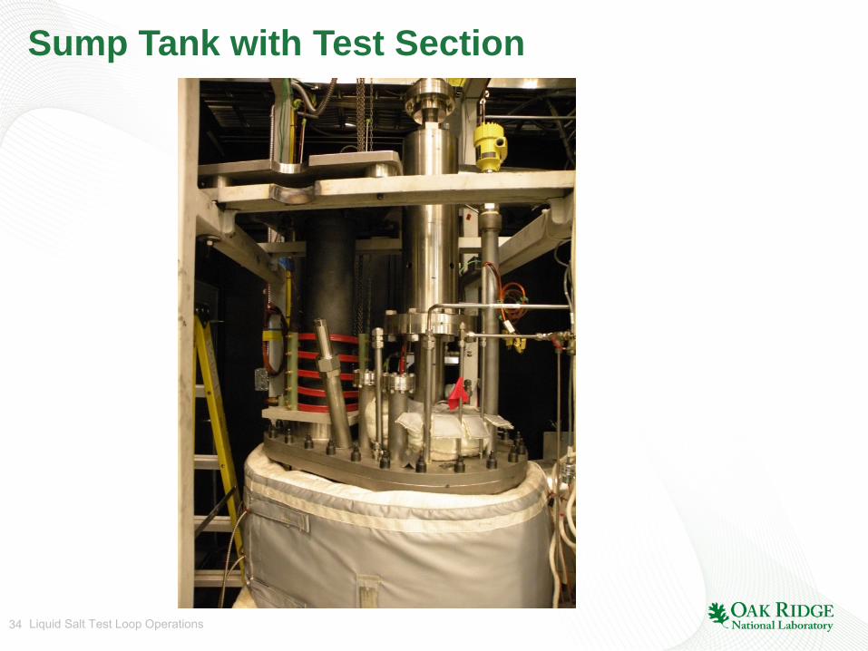
Sump Tank with Test Section

35 Liquid Salt Test Loop Operations
25 heater zones used between crucible and loop systems, with total power over 20 kW
Heater Zone Control Display

36 Liquid Salt Test Loop Operations
Display data during HF/H2 sparging