Liquid Rocket Engine and Test System - University of Akron
46
The University of Akron The University of Akron IdeaExchange@UAkron IdeaExchange@UAkron Williams Honors College, Honors Research Projects The Dr. Gary B. and Pamela S. Williams Honors College Spring 2021 Liquid Rocket Engine and Test System Liquid Rocket Engine and Test System Ronnie Wallingford The University of Akron, [email protected] Grace Ann Phillips The University of Akron, [email protected] Blake Bowser The University of Akron, [email protected] Jack Dalton The University of Akron, [email protected] Follow this and additional works at: https://ideaexchange.uakron.edu/honors_research_projects Part of the Propulsion and Power Commons Please take a moment to share how this work helps you through this survey. Your feedback will be important as we plan further development of our repository. Recommended Citation Recommended Citation Wallingford, Ronnie; Phillips, Grace Ann; Bowser, Blake; and Dalton, Jack, "Liquid Rocket Engine and Test System" (2021). Williams Honors College, Honors Research Projects. 1355. https://ideaexchange.uakron.edu/honors_research_projects/1355 This Dissertation/Thesis is brought to you for free and open access by The Dr. Gary B. and Pamela S. Williams Honors College at IdeaExchange@UAkron, the institutional repository of The University of Akron in Akron, Ohio, USA. It has been accepted for inclusion in Williams Honors College, Honors Research Projects by an authorized administrator of IdeaExchange@UAkron. For more information, please contact [email protected], [email protected].
Transcript of Liquid Rocket Engine and Test System - University of Akron

The University of Akron The University of Akron
IdeaExchange@UAkron IdeaExchange@UAkron
Williams Honors College, Honors Research Projects
The Dr. Gary B. and Pamela S. Williams Honors College
Spring 2021
Liquid Rocket Engine and Test System Liquid Rocket Engine and Test System
Ronnie Wallingford The University of Akron, [email protected]
Grace Ann Phillips The University of Akron, [email protected]
Blake Bowser The University of Akron, [email protected]
Jack Dalton The University of Akron, [email protected]
Follow this and additional works at: https://ideaexchange.uakron.edu/honors_research_projects
Part of the Propulsion and Power Commons
Please take a moment to share how this work helps you through this survey. Your feedback will
be important as we plan further development of our repository.
Recommended Citation Recommended Citation Wallingford, Ronnie; Phillips, Grace Ann; Bowser, Blake; and Dalton, Jack, "Liquid Rocket Engine and Test System" (2021). Williams Honors College, Honors Research Projects. 1355. https://ideaexchange.uakron.edu/honors_research_projects/1355
This Dissertation/Thesis is brought to you for free and open access by The Dr. Gary B. and Pamela S. Williams Honors College at IdeaExchange@UAkron, the institutional repository of The University of Akron in Akron, Ohio, USA. It has been accepted for inclusion in Williams Honors College, Honors Research Projects by an authorized administrator of IdeaExchange@UAkron. For more information, please contact [email protected], [email protected].

LIQUID ROCKET ENGINE AND TEST SYSTEM Final Report for 4600:402-461/4600:402-497 Senior/Honors Design
By: Blake Bowser
Jack Dalton
Grace Phillips
Ronnie Wallingford
Project Sponsor: Dr. Manigandan Kannan
Honors Department Advisor: Dr. Scott Sawyer
Honors Reader 1: Dr. Francis Loth
Honors Reader 2: Charles Campbell
3 May 2021
Mechanical Engineering Senior Project No. 38

ii | P a g e
ABSTRACT
The goal of this project is to design the University of Akron’s first design team built liquid
propulsion rocket engine and testing system. Liquid propulsion rocket engines are widely used
on space launch vehicles in comparison to solid phase propulsion engines and other engine types
such as hypergolic engines and liquid hybrid engines, however in the collegiate rocketry
environment they are less frequently used due to their complexity and high cost. The creation of
this engine and testing system will create new opportunities for the Akronauts Rocket Design
Team moving forward, allowing the team to enter more prestigious competitions, and will also
enable students to better pursue opportunities in the space and defense industry by exposing them
to more relevant industry experiences.
The liquid rocket engine designed by the team will utilize ethanol and liquid nitrous oxide to
generate approximately 500 lbf of thrust. An accompanying test system was designed for this
motor with modularity and safety in mind. These design foci will enable the team to safely test
motors of various thrust capacities without needing to make major modifications to the system.
To verify the safety of the rocket engine and testing system, the team did hand calculations
and computer analysis of critical components and their designs. To further verify the safety and
functionality of the systems, physical testing of individual components and assembled
subsystems will be completed once components are acquired.

iii | P a g e
TABLE OF CONTENTS
1. INTRODUCTION.......................................................................................................................... 1
1.1. PROJECT OBJECTIVES ................................................................................................................... 1
2. DESIGN .......................................................................................................................................... 2
2.1. CONCEPTUAL DESIGN .................................................................................................................. 2 2.1.1. PROPELLENT SELECTION ................................................................................................................ 2
2.1.2. CONCEPTUAL MOTOR DESIGN ...................................................................................................... 3
2.2. PHYSICAL DESIGN ......................................................................................................................... 7 2.2.1. MOTOR ................................................................................................................................................. 8
2.2.2. FEED SYSTEM ................................................................................................................................... 10
2.2.2.1. TUBING AND FITTINGS ......................................................................................................... 11
2.2.2.2. CONTROLS .............................................................................................................................. 12
2.2.2.3. DATA ACQUISITION ............................................................................................................... 14
2.2.2.4. SAFETY DEVICES ................................................................................................................... 15
2.2.3. TEST STAND ..................................................................................................................................... 15
2.2.4. FUEL AND OXIDIZER TANKS ........................................................................................................ 18
3. DESIGN VERIFICATION ......................................................................................................... 23
3.1. TESTING PROCEDURES ............................................................................................................... 23 3.2. DESIGN ANALYSIS ....................................................................................................................... 23 3.3. UNIVERSITY SAFETY APPROVAL ............................................................................................. 28 3.4. RELEVANT DESIGN STANDARDS ............................................................................................. 28
4. COST AND SCHEDULE ............................................................................................................ 29
4.1. COST ANALYSIS ........................................................................................................................... 29 4.2. SCHEDULE ..................................................................................................................................... 29
5. CONCLUSION ............................................................................................................................ 31
5.1. ACCOMPLISHMENTS ................................................................................................................... 31 5.2. UNCERTAINTIES ........................................................................................................................... 31 5.3. ETHICAL CONSIDERATIONS ...................................................................................................... 31 5.4. FUTURE WORK .............................................................................................................................. 32
6. ACKNOWLEDGEMENTS ........................................................................................................ 33
7. APPENDIX ................................................................................................................................... 34
7.1. APPENDIX A: EQUATION VARIABLES ..................................................................................... 34 7.2. APPENDIX B: EQUATIONS FROM CAMPBELL ET AL[1] ......................................................... 35
8. REFERENCES ............................................................................................................................. 39

iv | P a g e
TABLE OF FIGURES Figure 1 – Propellant Choices ......................................................................................................... 2 Figure 2 – Basic Depiction of a VAPAK Feed System Setup (Drawn by Charles Campbell)....... 3 Figure 3 – ProPep3 Output ............................................................................................................. 4 Figure 4 – RPA Output ................................................................................................................... 5 Figure 5 – Over-expanded, perfectly expanded (most efficient), and under-expanded flow
examples, courtesy of Heister et al[6] .............................................................................................. 6 Figure 6 – Isometric view of Motor ................................................................................................ 8 Figure 7 – Cross Section View of the Motor ................................................................................ 10 Figure 8 – Piping and Instrumentation Diagram of Current System ............................................ 11 Figure 9 – LabJack T7 Pro DAQ Board ....................................................................................... 13 Figure 10 – Relay Wiring Diagram - Credits: Jonathan Davis ..................................................... 13 Figure 11 – Thermocouple Chart by Thermometrics Corporation ............................................... 14 Figure 12 – Current Test Stand Model ......................................................................................... 16 Figure 13 – Reinforced Frame Assembly ..................................................................................... 16 Figure 14 – Sled Guide Rails ........................................................................................................ 17 Figure 15 – Fuel Tank Support Frames ........................................................................................ 17 Figure 16 – Test Sled and System Piping ..................................................................................... 18 Figure 17 – Un-Flanged Tank Design with Caps and Fuel Tank Piston ...................................... 19 Figure 18 – Flanged Tank Design Assembly (Left) with Fuel Tank Piston (Right) .................... 19 Figure 19 – Fuel Tank Isometric View (Left), Fuel Tank Side View (Right) .............................. 20 Figure 20 – Fuel Tank Top Cap (Left), Fuel Tank Bottom Cap (Right) ...................................... 21 Figure 21 – Nitrous Oxide Tank Isometric View (Left), Nitrous Oxide Tank Side View (Right)21 Figure 22 – Nitrous Oxide Tank Top Cap (Left), Nitrous Oxide Tank Bottom Cap (Right) ....... 22 Figure 23 – Test Stand Stress Analysis ........................................................................................ 23 Figure 24 – Test Stand Deflection ................................................................................................ 24 Figure 25 – Full Motor Assembly FEA Results ........................................................................... 25 Figure 26 – Injector Plate FEA Results ........................................................................................ 25 Figure 27 – Casing Hoop Stress FEA Results .............................................................................. 26 Figure 28 – Nozzle Carrier FEA Results ...................................................................................... 26 Figure 29 – Blast Shield FEA Results .......................................................................................... 27 Figure 30 – Engine Mounting Plate FEA Results ......................................................................... 27 Figure 31 – University of Akron's Jet Propulsion Building .......................................................... 28

v | P a g e
TABLE OF EQUATIONS Equation 1 – Fourier’s Law for Radial Heat Travel in Cylinders ................................................... 4 Equation 2 – Specific Impulse ........................................................................................................ 6 Equation 3 – Used to Find Throat Pressure .................................................................................... 6 Equation 4 – Used to Find Throat Area .......................................................................................... 7 Equation 5 – Mach Flow at the Exit ............................................................................................... 7 Equation 6 – Exit Area .................................................................................................................... 7 Equation 7 – Thrust ......................................................................................................................... 7 Equation 8 – Mass Flow ................................................................................................................. 7 Equation 9 – Fuel Mass Flow Rate ................................................................................................. 7 Equation 10 – Oxidizer Mass Flow Rate ........................................................................................ 7 Equation 11 – Compression Ratio .................................................................................................. 9 Equation 12 – Stretch ...................................................................................................................... 9 Equation 13 – Mass Flow with Discharge Coefficient ................................................................... 9 Equation 14 – Thrust ..................................................................................................................... 35 Equation 15 – Throat Pressure ...................................................................................................... 35 Equation 16 – Throat Area ............................................................................................................ 35 Equation 17 – Exit Mach Number ................................................................................................ 35 Equation 18 – Exit Area ................................................................................................................ 35 Equation 19 – Design Efficiency .................................................................................................. 35 Equation 20 – Characteristic Length............................................................................................. 36 Equation 21 – Chamber Mach Number ........................................................................................ 36 Equation 22 – Variable B for Characteristic Length Equation ..................................................... 36 Equation 23 – Variable S for 𝜁2 ................................................................................................... 36 Equation 24 – Prandtl Number for Chamber Gases...................................................................... 36 Equation 25 – Inlet Stagnation Temperature ................................................................................ 36 Equation 26 – 𝜁2 for Characteristic Length .................................................................................. 36 Equation 27 – Contraction Ratio................................................................................................... 36 Equation 28 – Used to Find Area of the Throat ............................................................................ 37 Equation 29 – Injector Ports Cross-Sectional Area ...................................................................... 37 Equation 30 – Heat Transfer Coefficient ...................................................................................... 37 Equation 31 – Solving for σ .......................................................................................................... 37 Equation 32 – Characteristic Velocity .......................................................................................... 37 Equation 33 – Heat Removed as Nitrous Oxide Vaporizes .......................................................... 37 Equation 34 – Change in Temperature ......................................................................................... 37 Equation 35 – Density ................................................................................................................... 38 Equation 36 – Mass Flow Rate ..................................................................................................... 38 Equation 37 – Loss Factor ............................................................................................................ 38 Equation 38 – True Mass of Liquid after a Given Time ............................................................... 38

vi | P a g e
TABLE OF TABLES Table 1 – Input Rocket Propulsion Analysis Data ........................................................................ 11 Table 2 – Piping Sizes and Flow Velocities ................................................................................. 12 Table 3 – Tank Design Decision Matrix ....................................................................................... 20 Table 4 – Total System Cost ......................................................................................................... 29 Table 5 – Project Timeline ............................................................................................................ 30 Table 6 – Equation Variable Table ............................................................................................... 34

1 | P a g e
1. INTRODUCTION
This project aims to design a liquid rocket engine and testing system in order to help expand
the design team’s knowledge of liquid engine propulsion. The design is motivated by the desire
to gain industry relevant experience utilizing engineering skills learned from fluid mechanics,
mechanical metallurgy, heat transfer, concepts of design, and chemistry. The knowledge and
design of the liquid engine and test stand would help make the Akronauts Rocket Design Team
stand out at competition, as very few collegiate design teams have successfully developed liquid
rocket engines. The design team has previously designed and manufactured solid rocket engines,
however the development of a liquid engine would help the team gain more industry recognition
and experience for industry applications, as well as be a powerful recruitment tool for the design
team and the University. The liquid engine would also allow the team to use propellants with
higher efficiencies. The use of a testing system would help the team safely test the propellant
chemicals. The testing system design would ideally be a mobile system located on a trailer bed,
and it would utilize an 80/20 adjustable rail with fire walls between the engine, tanks, and
controls.
1.1. PROJECT OBJECTIVES
The goal of this project is to design a liquid rocket engine and an accompanying testing
system. To meet this goal, the team has outlined the following key objectives: system design,
project safety, and system fabrication and verification.
The system design encompasses both conceptual design of the engine and physical design of
the engine and test stand. These two design subsets are important to distinguish, as the
conceptual design is what defines the physical dimensions of the motor and gives critical values
for the safe design of system components. Once these dimensions and values are determined, the
components can be designed with manufacturability, modularity, and strength in mind. For this
objective, the goal was to design an engine that could generate approximately 500 lbf of thrust
and would safely operate with an oxidizer vapor pressure of 750 psi and a test stand that could
withstand and record the motor thrust.
Project safety is very important to the success of this project. This objective was broken
down into the testing and design verification of the systems and University Safety approval.
Design verification was done using hand calculations and computer simulations to ensure that
the factors of safety in the system components were appropriate. Testing the components to
verify they operate as intended will ensure that the system also operates safety. University Safety
approval was important to get to progress with project construction and testing and to get outside
verification on the safety of the project. Unfortunately, obtaining approval to construct the
engine and test stand through the university's safety department proved to be a long process.
Ideally this project would result in the fabrication of the rocket engine and test system and
subsequent testing to verify their performance, however the global coronavirus pandemic has
caused considerable financial strain to the University and the Akronauts Rocket Design Team, so
funding for this project is very limited. Additionally, due to the delay in getting university safety
approval, the acquisition and assembly of components was delayed and will be completed by the
Akronauts once the project is passed on to the design team.

2 | P a g e
2. DESIGN
For this project, the design process was broken up into two stages: the conceptual design of
the engine and the physical design of key components and assemblies. The conceptual design
was completed first to determine key performance information from the system. Once this design
stage was complete, values and geometries from the conceptual design were used in the design
process of the physical components to ensure that the system could be manufactured and would
operate safely.
2.1. CONCEPTUAL DESIGN
There were two key components to the conceptual design of the engine: the propellant
selection and motor geometry. Before a conceptual design for the motor geometry can be created
the propellants used in the system needed to be determined. Once the propellants were
determined, their known properties and combustion characteristics were used to generate a motor
geometry that meet the pressure and thrust goals of the system.
2.1.1. PROPELLENT SELECTION
The liquid bi-propellant rocket engine will feature an oxidizer and fuel that will be combined
at equal pressure inside the combustion chamber prior to ignition. The team chose to use Liquid
Nitrous Oxide as the oxidizer and Ethanol as the fuel for the engine. These propellants were
selected as they are the safest to use and easiest to acquire of the propellants considered. A
comparison of the considered propellants can be seen below in Figure 1. The team’s decision to
use these propellants was approved by the University of Akron’s safety department.
Figure 1 – Propellant Choices

3 | P a g e
To operate the engine, pre-pressurized nitrous oxide vapor will be used to drive a piston that
pressurizes the ethanol. Just before the injection plate, independently controlled regulator valves
will be used to equalize the pressures.[1] A diagram of this system can be seen below in Figure 2.
Figure 2 – Basic Depiction of a VAPAK Feed System Setup (Drawn by Charles Campbell)
2.1.2. CONCEPTUAL MOTOR DESIGN
ProPep3 is a propellant analysis program typically used for solid phase motors. This program
has assisted UA’s rocket design team in created SRAD (student researched and designed) solid
fuel motors for the past few years. It gives basic data from a motor’s chemical concentration and
outputs items such as specific impulse, combustion chamber temperature, and so on. Assuming a
combustion chamber pressure of 400psi, the system will have an approximate combustion
chamber temperature of 3000K and a specific impulse of 200s based on a 4:1 oxidizer-fuel ratio
for 298 K Nitrous-Oxide and 95% Ethanol.[2,3,4] This information provides clarity on the need for
thermal protection when selecting what type of material will be used for the main components of
the engine. As explained by the team in the proposal, the team will be using mainly aluminum
engine parts for safety reasons, as aluminum is widely recognized as a non-frangible material,
unlike many steels. The program outputs can be seen below, in Figure 3.

4 | P a g e
Figure 3 – ProPep3 Output
With this in mind, one can use Fourier’s Law for radial heat travel in cylinders (Equation 1)
to examine the heat conduction through the aluminum combustion chamber and note that for a
relative burn time of 5-10s, there will be enough heat conduction to make aluminum fail as a
pressure holding device. This means that a thermal protection system will need to be in place to
keep the engine from failing due to thermal degradation in the material. A cheap and simple way
to do this is by using a phenolic combustion chamber liner, which is often used for solid rocket
boosters and amateur rocketry engines. Phenolic liners are well insulating tubes of a phenolic
cardboard mixture that is one time use but will protect the engine long enough for a stable and
successful burn. The team will alternatively utilize a mix of epoxy and phenolic microbeads for a
castable version of this component.
𝑄 =2𝜋𝑘𝐿(𝑇𝑖 − 𝑇𝑒)
ln(𝑟𝑒𝑟𝑖)
Equation 1 – Fourier’s Law for Radial Heat Travel in Cylinders
The throat of the engine will also have to be thermally protected since it will be experiencing
a large amount of heat. This can be done by using a graphite insert for the throat of the
converging diverging system. Graphite can handle heat and pressure much better in comparison
to aluminum and will withstand the heat with the approximate burn times mentioned above.
RPA (Rocket Propulsion Analysis) is a liquid engine program that takes a multi-variable,
multi-input approach at dimensioning an engine based on general constraints, fuel and oxidizer,
mixture ratio, atmospheric conditions, and many others.[5] The program outputs expected engine
thrust when optimized for the input conditions as well as vacuum conditions. These results can
be hand calculated using the equations in APPENDIX B: EQUATIONS FROM CAMPBELL
ET AL[1] and following the process outlined in the “Design and Testing of a Low-Cost
Bipropellant Liquid Rocket Engine.”[1] Our team used this program as shown below in Figure 4.

5 | P a g e
Figure 4 – RPA Output
Thus, the team’s expected engine parameters shown will output an optimized thrust (at sea
level) of 2.23kN (~510lbf) and a vacuum thrust of 2.48kN (~557lbf) when in space. This is
advantageous as thrust will not be lost but gained for the engine when propelling through the
atmosphere. At the team’s scale, this will be useful. However, in industry, staged liquid rocket
booster engines would need to be optimized for the various layers of the atmosphere as to lower
cost (fuel waste) and an increase in general efficiency. Flow exit expansion is shown in Figure 5
provided by Stephen Heister et al.[6]

6 | P a g e
Figure 5 – Over-expanded, perfectly expanded (most efficient), and under-expanded flow examples, courtesy of Heister et al[6]
The other important quantity in regards to engine characterization is the specific impulse,
which measures an engine’s efficiency with respect to thrust and fuel weight flow rate. This can
be calculated using Equation 2.
𝐼𝑠𝑝 =𝐹
�̇�𝑔
Equation 2 – Specific Impulse
The team’s engine shows a specific impulse of approximately ~200s in ProPep3, and an
impulse of ~240s using RPA. RPA shows a more accurate value, since it involves more
information regarding the engine, aside from just propellant choices.
RPA also outputs fuel consumption based on the engine performance. It is shown that the
engine will require approximately 1.04kg/s of total mass flow, 0.84kg/s of oxidizer, and 0.21kg/s
of fuel. Assuming a 6 second burn time, the team can supply the engine with ~5.24kg (11.5lb) of
oxidizer, and ~1.31kg (2.88lb) of fuel. Therefore, the team must account volumetrically for each
of these tank sizes on the testing system.
Using the values from RPA, the specific impulse can be hand-calculated through the
following equations, found in Stephen Heister et al.[6] Throat pressure can be solved for using
chamber pressure and the specific heat ratio, as seen below in Equation 3.
𝑝𝑐𝑝𝑡
= [𝛾 + 1
2]
𝛾𝛾−1
Equation 3 – Used to Find Throat Pressure
Assuming choked flow, Equation 4 can be used to find the throat area.

7 | P a g e
�̇� =𝛾𝑝𝑡𝐴𝑡𝑎𝑡
Equation 4 – Used to Find Throat Area
Using a traditional hand calculation approach, the Mach flow at the exit is found from
Equation 5.
𝑀𝑒 = √(2
𝛾 − 1) [(
𝑝𝑐𝑝𝑎)
𝛾−1𝛾
− 1]
Equation 5 – Mach Flow at the Exit
Using the previously calculated values, the exit area can be calculated using Equation 6.
𝐴𝑒 = (𝐴𝑡𝑀𝑒
) [1 + (
𝛾 − 12 )𝑀𝑒
2
(𝛾 + 12 )
]
𝛾+12(𝛾−1)
Equation 6 – Exit Area
Using the previous two solved values, Equation 7 can be used to calculate thrust with the
inclusion of 𝑝a and 𝑝e.
𝐹 = �̇�𝑉𝑒 + (𝑝𝑒 − 𝑝𝑎)𝐴𝑒 Equation 7 – Thrust
The general mass flow equation is shown in Equation 8, below.
�̇� = 𝜌𝑉𝐴 Equation 8 – Mass Flow
Mass flow rates of the oxidizer and fuel can be separated in the following equations:
𝑚𝑓̇ =�̇�
1 + 𝑟
Equation 9 – Fuel Mass Flow Rate
𝑚𝑜𝑥̇ =𝑟�̇�
1 + 𝑟
Equation 10 – Oxidizer Mass Flow Rate
A comprehensive list of the variables used in this document can be found in APPENDIX A:
EQUATION VARIABLES.
2.2. PHYSICAL DESIGN
Using the values and geometries derived from the conceptual design section, physical
designs for the motor, feed systems, test stand, and oxidizer and fuel tanks were created. The

8 | P a g e
design of these components focused on the manufacturability, modularity, and safety of the
systems.
When accounting for the repeatability of tests, the system was designed to easily be able to
refill the test engine’s fuel and oxidizer tanks. A plan was set in place to use a combination of a
check valve, hand valve, and solenoid valve to actuate the re-filling of the oxidizer portion of the
engine. The fuel tank will have to be removed from the test stand by hand and refilled due to the
piston pressurization application being used to obtain equal pressure output of the fuel and
oxidizer. The convenience of also having the engine portion of the design modular, will also
assist the team in replacing the single use phenolic liner for the combustion chamber. The
downside of this is that the engine will not be able to be fired back-to-back without direct human
intervention. This does conveniently allow for direct post-burn operational assessment for the
system after each test, which is beneficial for characterizing the possible faults of the system
from single test runs.
2.2.1. MOTOR
The motor is the most essential component of the rocket, and the rest of the components are
built around the motor to achieve the best performance. The motor is basically a pressure vessel
that is built to contain and direct the combustive energy. The designed motor can be seen below
in Figure 6. The aft of the motor case will contain the nozzle, and the motor casing will be
insulated with a thin layer of phenolic liner. The oxidizer (nitrous oxide) and fuel (ethanol) will
be pressurized before reaching the injection plate.[7] From there the mixture will enter the
combustion chamber at equal pressures. The nozzle is responsible for accelerating the combusted
gases through a converging-diverging profile at supersonic speeds. Due to the high levels of heat
the nozzle experiences, the nozzle will be made of graphite. The nozzle must be machined with a
high degree of accuracy to achieve the smooth and precise geometry needed for stable flight.
Efficiency of the thrust is determined by the shape of the nozzle. Longer nozzles with shallower
angles through the converging duct yield the best efficiency, however, they will also increase
viscous drag and weight. Due to this tradeoff, simulations were performed to maximize the
power output.[1]
Figure 6 – Isometric view of Motor

9 | P a g e
The motor design has been finalized, and the manufacturing process has begun. The motor is
designed to have a flanged connection between the injector plate and chamber, and an ID
retention snap ring for the nozzle and aluminum retaining core. The nozzle was designed to be
manufactured from graphite since it is a highly heat tolerant material that can maintain the nozzle
geometry for the duration of the burn. An aluminum nozzle retainer was designed to hold the
graphite nozzle in place. To avoid losing engine efficiency both components were fitted with a
double diametric O-ring seal. A compression ratio of 20.8% and 20.28% was acquired for the
graphite nozzle and the aluminum retaining ring using Equation 11.
𝐶𝑜𝑚𝑝𝑟𝑒𝑠𝑠𝑖𝑜𝑛𝑅𝑎𝑡𝑖𝑜 =𝐶𝑆𝑂𝑅𝑖𝑛𝑔 − 𝐺𝑙𝑎𝑛𝑑𝐷𝑒𝑝𝑡ℎ
𝐶𝑆𝑂𝑅𝑖𝑛𝑔𝑥100
Equation 11 – Compression Ratio
It should also be noted that the O-ring groove on the flanged section between the casing and
the injection plate has a compression ratio of 28% since static face seals are generally required to
have higher compression ratios for better functionality.[8] All O-ring measurements were also
taken to have between 0-5% stretch as recommended using Equation 12.[8]
𝑠𝑡𝑟𝑒𝑡𝑐ℎ =𝐼𝐷𝑔𝑙𝑎𝑛𝑑 − 𝐼𝐷𝑂𝑅𝑖𝑛𝑔
𝐼𝐷𝑂𝑅𝑖𝑛𝑔
Equation 12 – Stretch
The aluminum casing’s combustion chamber region (shown in blue in Figure 7), is an
ablative material that was formulated and briefly tested by the rocket design team. The team’s
brief testing showed that a material of approximately 3/8” thickness can melt a penny on the
surface of the material using a blow torch for a period of ~100 seconds before a thermocouple on
the opposite side of the material shows temperatures over 100F. The ablative is a heat protection
component that stops the aluminum casing from being over-heated during motor burn, and thus
exploding. It is a pourable material that can be casted to shape. The rocket design team’s student
members will be creating a casting tube to provide the necessary component for the engine.
The injector plate is designed to provide a mixture ratio of 4:1 for the oxidizer and fuel,
respectively. The geometry of the plate was designed to encourage a good mixture of fuel and
oxidizer in the combustion chamber such that there will be an efficient burn in the engine. A
reference injection plate geometry and the resources to characterize the plates were provided by
Charles Campbell.[1] As designed, the injector plate contains 6 ports total. One port will be used
to get readings for a pressure transducer, a single port with 4-1mm diameter injection lines will
be used for the fuel, and 4 ports each containing a single 1.89mm diameter port will be used for
the oxidizer. These diametric values were acquired from Heisters Rocket Propulsion book, using
the discharge coefficient (CD) based equation to solve for mass flow, as seen below in Equation
13.
𝑚𝑒̇ = 𝐶𝐷𝐴√2𝜌𝑔∆𝑝 Equation 13 – Mass Flow with Discharge Coefficient
However, since the mass flow rate is known from the Rocket Propulsion Analysis program,
one can back-solve for injection area for fuel and oxidizer separately. This equation also requires
pressure drop across the injection plate. Heister states that it is of the utmost importance that the

10 | P a g e
pressure drop be between 5-50% of the combustion chamber pressure (which is 400psi), thus the
team designed the engine to have an 80 psi pressure drop which is 20% of the combustion
chamber theoretical pressure.[6] ¼" NPT to ¼" AN pipe fittings were used to attach the feed
systems to the injector plate. AN fittings are typically used in high pressure, rigid piped feed
systems since they are designed to be fitted with a flared tube face which is compressed onto the
37-degree angle face of the fitting. ¼" NPT tapered fittings are used on the injector plate side for
their good face mounting capabilities and diametric size, which is needed for the injector plate
design.
To update the design considerations, a pressure transducer port was included into the model
using the same ¼” NPT to ¼” AN on the injector plate. The pressure transducer, which was
donated by The Spaceship Company, a Stellar Technologies AN port 0-5000psi range
transducer, will not be able to handle the 3000K theoretical combustion chamber temperature
that is expected. Thus, the pressure transducer will actually be installed on a line leading off of
the tank that will have thermal insulation paste. Pressure will still be able to read through the
thermal insulation paste, although a small data damping coefficient and error may likely be
present when recording pressure.
Figure 7 – Cross Section View of the Motor
2.2.2. FEED SYSTEM
The piping and instrumentation diagram, shown below in Figure 8, utilizes many complex
systems brought together to accomplish the most cost-effective, yet safe approach to creating a
feed system that includes controls, data acquisition, and safety relief devices.

11 | P a g e
Figure 8 – Piping and Instrumentation Diagram of Current System
2.2.2.1. TUBING AND FITTINGS
Piping and fittings are extremely important in characterizing the extent at which an engine
may be able to perform. The engine design itself has feed rate requirements that must be satisfied
based on how much material can flow to the injector plate at any given time. The injector plate
requirements are set to the values mentioned in Table 1.
Input Rocket Propulsion
Analysis Data
Oxidizer Mass Flow kg/s
0.083837
Fuel Mass Flow kg/s
0.20959
Chamber Pressure psi
400 Table 1 – Input Rocket Propulsion Analysis Data
The piping dimensional requirements will need to be different with regards to the fuel and
oxidizer. The oxidizer mass flow rate, being higher, requires a larger pipe dimension. Therefore,
3/8” 316L Stainless Steel tubing was selected for the oxidizer. 316L Stainless Steel is a fantastic
material when affordable. It has excellent chemical resistivity and has a high-pressure rating for

12 | P a g e
smaller tubing, which is widely known. The current tubing, donated by the University of Akron,
is Swagelok High Purity Stainless Steel Tubing, with a pressure rating of 3,330psi. This yields an
effective factor of safety of 3+ for the working pressure of the oxidizer portion of the system.
1/4” 316L Stainless Steel is used on the fill line and fuel lines, since flow rate is less of a concern
upon filling the oxidizer day tank and the mass flow rate requirement for the fuel is lower.
Using a simple mass flow rate equation in regard to material density and area of the pipe, the
velocities of the liquids within each piping size is calculated and can be seen below in Table 2.
The goal is to keep each pipe’s speed underneath Mach 0.3, which is well known as the point
where turbulent flow begins.
Piping Sizes and Flow Velocities
Material
316L SS Pipe Size 3/8” Flow Area (in2)
ID (Assuming 0.035” Wall Thickness) 0.305 0.07306166415
OD 0.375
Pipe Size 1/4” Flow Area (in2)
ID (Assuming 0.035” Wall Thickness) 0.18 0.02544690049
OD 0.25
Oxidizer Flow Velocity (m/s) Mach Value
1/4” Piping 64.92001235 0.18927113
3/8” Piping 22.61121634 0.06592191353
Fuel Flow Velocity (m/s) Mach Value
1/4” Piping 16.18044126 0.04717329812
3/8” Piping 5.635542023 0.01643015167 Table 2 – Piping Sizes and Flow Velocities
Fittings for the system will be Army-Navy (AN) style flared fittings. AN flared fittings are
37 degree angle fittings that are typically used in heavy-duty, off-roading, and aerospace
applications, as they are stronger and more robust than the typical 45 degree angle hydraulic
flared fitting typically used on commercial over-road vehicles. All connections directly to piping
will be flared, while adapters will be utilized when connecting valves and solid objects, such as
manifolds and the engine injector plate, which will utilize ¼” NPT connections.
2.2.2.2. CONTROLS
The test system accounts for the usage of two LabJack T7 Pro data acquisition units, in
which one will be used to control the system through the I/O ports, and the other will be used as
a DAQ. The LabJack T7 Pro that will be utilized for the control system of the test stand can be
seen below in Figure 9.

13 | P a g e
Figure 9 – LabJack T7 Pro DAQ Board
The current system was designed by Jon Davis and Jon Spencer due to their electrical
expertise. In the future, the Akronauts avionics team will take over the design and verification of
the controls system, as they have experienced computer and electrical engineering students on
the sub-team. Preliminarily, electrically actuated valves will be placed on a system that uses high
amperage rated relays, which will connect externally to an AC power source. This AC power
source may be a generator or direct grid hookup. The LabJack T7 has digital I/O pins which will
actuate the relays, sending power from the external power source to the valves to be actuated.
This is shown in a simple diagram below in Figure 10.
Figure 10 – Relay Wiring Diagram - Credits: Jonathan Davis

14 | P a g e
2.2.2.3. DATA ACQUISITION
All data acquisition devices are shown in Figure 8. Pressure transducers and thermocouples
will be utilized at key points to understand and characterize the feed system while also recording
and transmitting live data to make in-the-moment engine go or no-go decisions.
Thermocouples are chosen by type, with each type being differentiated by their rated values
and precision. A breakdown of the thermocouple types can be seen below, in Figure 11. As each
section of the system has differing temperature ranges, slightly different thermocouples will be
utilized at different locations on the stand.
Figure 11 – Thermocouple Chart by Thermometrics Corporation
A Type T thermocouple with a range from -325F to 700F is utilized on the oxidizer day tank
to account for the possible near cryogenic temperatures and critical temperatures at over 100F. A
Type J (32F to 1200F) thermocouple will be utilized for the feed system, to account for low
temperatures and upper range temperatures that could be seen if back pressure events are noted
in the feed lines, where combustion temperatures could be seen.
Pressure Transducers are also a vital component in determining if go/no-go conditions are
present. It is equally as important as temperature in regards to the characterization of the feed
system for the engine, as well as the pressure production in the combustion chamber. All these
components will help verify functionality, or the lack thereof, upon cold flow and hot fire testing.
Pressure sensors are simpler to pick, as 0-1000psi will be the range in which the Akronauts’
system will function at the most. The feed system pressure will not exceed 1000psi, and the
combustion chamber nominal theoretical value is 400psi. Therefore, any pressure transducer in
that range with the chemical resistivity capable of handling the fuel and oxidizer should be
capable of data acquisition if the accuracy of the transducer is within acceptable limits to the
team.

15 | P a g e
2.2.2.4. SAFETY DEVICES
The tanks, while designed to withstand a large factor of safety over the vapor pressure of
Nitrous between 70F-100F, will also be outfitted with a restriction orifice, also called a passive
vent. The passive vent is used to constantly vent the oxidizer, like what is seen on major launch
vehicles today. This helps keep tanks from experiencing an over-pressurization event during
system fill, engine standby, and engine run phases. The Akronauts will size the passive vent in
the future to accommodate a balance between material loss and pressure drop over time. The
current sizing of the vent is currently approximated to be a hole with a diameter of 1mm.
Two passive vents are currently located on the system. One is directly off the oxidizer tank,
which will experience the largest amount of pressure and will be the most safety critical as it is a
student designed pressure vessel. The other vent is located directly on the fill line. This vent is
designed to vent the fill line, such that the line will be atmospheric whenever test personnel
would have to approach or the system. This is on the system such that a reliance on the automatic
fill valve to depressurize the system is not necessary. This also doubles to remove excess
material from the fill tank. This is valuable in the case that the team would use a simple racing
nitrous tank, which comes in quantities slightly larger than the tank, so the rest of the material in
the fill tank can safely vent to atmosphere.
2.2.3. TEST STAND
The test stand has been designed on a trailer to make the system portable. The design team
recently got approval to store the system on campus, however the system will still need to be
transported to the testing area from the storage location. The test stand assembly, seen below in
Figure 12, is comprised of a reinforced frame for the thrust load cell, a set of rails for test sleds,
test sleds to accommodate different motor types, and frames for securing tanks for liquid rocket
engine testing. The designs of these four components were made with a goal of modularity in
mind, as the system should be able to accommodate both liquid and solid motors in a variety of
physical sizes and thrust capacities. Specific piping pathing, electronics locations, and the valve
panel location are in the process of being finalized based off available space, thermodynamic
impacts to the fluids, and material cost optimizations. The test stand will also use solenoid valves
and an external power source to activate the solenoid valves. The team plans to use an external
generator to achieve the needed power output for valve actuation. Data acquisition and controls
of these mechanisms are also mentioned above in FEED SYSTEM.

16 | P a g e
Figure 12 – Current Test Stand Model
Although the liquid motor being designed in tandem with the test stand only produces a
thrust of approximately 500 lbf, the reinforced frame for the thrust load cell was designed to be
able to withstand tests of up to 2000 lbf without failing. The frame, seen below in Figure 13,
will be secured to the trailer by bolts that pass through structural beams in the trailer, further
increasing the rigidity of the system. ANSYS analysis indicates that the system can withstand
thrust of over 3000 lbf without failing, giving the system a factor of safety of at least 1.5 when
testing at maximum capacity, however further physical testing will be done to ensure the safety
and strength of the system. The mounting point for the load cell can accommodate load cells
ranging from 500 lbf capacity to 2000 lbf capacity, enabling the team to interchange load cells
based on future testing needs. The reinforced frame assembly will be made from welded steel
tube and can be seen in the figure below.
Figure 13 – Reinforced Frame Assembly
Rails were added to the test stand in order to accommodate a test sled for the system. This
feature, as seen in Figure 14 below, will aid the test stand functionality in several ways. The rails
will support the weight of the motors and sleds being tested to prevent any moment forces from
being applied to the load cells, it will ensure that the motor will be aligned properly with the load
cell for testing, and it enables different motor sizes and types to be tested without changes to the
test stand through the implementation of test sleds. This system was designed using extruded
aluminum T-slotted rail due to the low cost of the material and compatible rail guides, the ease of
assembly, and the availability of compatible brackets and hardware. Some linear support-rail
shafts were donated to the Akronauts, however the cost of compatible rail guides for these rails

17 | P a g e
exceeded the cost of acquiring new T-slotted rail, compatible guides for the T-slotted rail, and
mounting brackets for the new rail.
Figure 14 – Sled Guide Rails
The frame for securing liquid motor testing tanks was designed to accommodate a range of
tank sizes for future testing. To account for the difference in size between the oxidizer and fuel
tanks, the system will utilize two moveable base supports that will enable the team to align the
top of the tanks. An adjustable collar that can be moved up or down on the frame will secure the
top of the tanks. The combination of these two components will enable the system to
accommodate a variety of tank sizes in the future. Spacing above and below the tanks will enable
piping to be attached to the tanks, as well as facilitating the ability to refuel the tanks while
mounted to the test stand. This system was designed using extruded aluminum T-slotted rail for
its low cost and the wide availability of mounting brackets and hardware. Currently there are two
frames for the fuel tanks on the stand; one set for the current testing tank designs that sit right
behind the blast plate to minimize piping length to each other and to the motor, and one frame to
support the larger fill tanks for the system. Both frames, seen below in Figure 15, are
mechanically fastened to the test stand to make them easy to remove and reposition.
Figure 15 – Fuel Tank Support Frames

18 | P a g e
Structurally, the implementation of a test sled will ensure that the load cell solely bears the
motors thrust as the sled and rails will support the weight of the motor and any other hardware or
piping required to secure and operate the motor. Sleds will also enable new motors to be
mounted to the system without having to adjust any structural components on the test stand itself.
The current test sled can accommodate different liquid rocket engine designs by using a
standardized mounting plate for the system. The 1:4 oxidizer distribution manifold for the
current motor design is housed in a space between the motor and the blast plate, with mechanical
attachments holding the system in place such that any future manifold designs can be easily
implemented if needed. This space also leaves room for the piping to be installed between the
motor and blast plate, allowing the team to utilize different piping layouts as needed with
different future motors. For future solid rocket motors, either a different test sled could be
designed to support the motor without a need for piping accommodations, or the motor being
tested will need to incorporate a custom forward closure to attach the motor to the standardized
mounting plate. To ensure the safety of the system, the strength of the test sleds will be verified
using Finite Element Analysis (FEA). FEA of the current test sled can be seen in DESIGN
ANALYSIS.
Figure 16 – Test Sled and System Piping
Although the type of piping being used in the system has been determined, the specific
pathing of the piping is constantly changing as components and their locations are updated. The
current design utilizes a combination of rigid and flexible piping. The current layout of the test
sled piping can be seen above in Figure 16.
2.2.4. FUEL AND OXIDIZER TANKS
The liquid engine test stand houses two tanks to feed liquid nitrous oxide (oxidizer) and
ethanol (fuel) to the injector plate of the liquid engine. The design of these tanks is important to
ensure that they can hold the proper amounts of liquids and can withstand the pressure from
these propellants. Both the oxidizer and fuel tanks have a similar external design, with slightly
different input and output ports on their caps. The fuel tank also has a piston on the inside.
During the design phase for these tanks, two competing designs were considered by the team.
These two designs were referred to as the flanged and un-flanged tank designs. The un-flanged
design, see Figure 17, consists of two caps that fit into the tube with o-rings and retention rings.
The flanged design, see Figure 18, consists of flanges welded to each side of the tank. The caps
for the flanged tank bolt onto the flanges that are welded onto the tank. Each cap for both designs

19 | P a g e
would have the necessary ports to ensure their respective liquid would be inputted and outputted
properly.
Figure 17 – Un-Flanged Tank Design with Caps and Fuel Tank Piston
Figure 18 – Flanged Tank Design Assembly (Left) with Fuel Tank Piston (Right)
In order to determine which design was best for this application, the team made a decision
matrix, see Table 3. The team considered the ease of design, ease of manufacture, reusability,
safety, cost, and test stand integration. The tank’s safety was determined to be the most important
criterion since this system needs to be able to withstand pressure. Next, the ease of manufacture
was determined to be the second most important criteria. Ease of manufacture is important to the
team since students need to be able to fabricate this system. Since the Akronauts are planning on
using this system for years to come, a system that can be remanufactured easily in the future if
needed should be considered. Next, the team considered reusability. Reusability is important so
components can be used multiple times to reduce waste and the need to remanufacture the tanks
for every test. Test stand integration was equally as important as reusability, since the goal is to
have the tanks held in place on the test stand with easy access to all ports. Lastly, the team
considered ease of design and cost.

20 | P a g e
Tank Design Decision Matrix
Tank Options
Criteria Weight Un-Flanged Tank Flanged Tank
Score Total Score Total
Ease of Design 0.10 6 0.60 9 0.90
Ease of
Manufacture
0.20 7 1.40 9 1.80
Reusability 0.15 7 1.05 10 1.50
Safety 0.30 6 1.8 10 3.00
Cost 0.10 10 1.00 7 0.70
Test Stand
Integration
0.15 6 0.90 10 0.90
Total 1 6.75 8.80 Table 3 – Tank Design Decision Matrix
Based on the criteria that was considered, the team determined that the flanged tank design
would be the best design. Out of the criteria considered, cost was the only consideration that the
flanged tank design was not the best. However, taking the reusability of the design into
consideration makes the cost over time more effective even though the upfront cost is greater.
The simplicity of the flanged tank design allows for easy manufacturing and assembly. The
design is also safer overall.
To ensure that the flanged tank would be able to work in this application, analysis and
calculations were conducted. These results can be found in DESIGN ANALYSIS.
The fuel tank assembly can be seen in Figure 19. This tank has one 1/4” NPT port on the top
cap for a 1/4” tube OD x 1/4” ANPT male fitting. This fitting will connect to a fitting on the top
cap of the oxidizer tank to control pressurization of the fuel tank. Inside of the fuel tank there is a
piston with o-rings to ensure the pressurized gas from the nitrous oxide tank does not mix with
the ethanol. This piston was also designed to ensure that it will not turn and get jammed into the
tank. The bottom cap has two 1/4” NPT ports for one 1/4” tube OD x 1/4” ANPT male fitting
and for one pressure transducer. The top and bottom cap fittings can be seen in Figure 20. The
length between the caps of this tank is 7.87”.
Figure 19 – Fuel Tank Isometric View (Left), Fuel Tank Side View (Right)

21 | P a g e
Figure 20 – Fuel Tank Top Cap (Left), Fuel Tank Bottom Cap (Right)
The oxidizer tank assembly can be seen in Figure 21. This tank has three 1/4” NPT ports on
the top cap and one 1/8” vent hole. The three NPT ports are for a pressure transducer, a 1/4” tube
OD x 1/4” ANPT male fitting, and a 3/8” tube OD x 1/4” ANPT male fitting. The 1/4” tube OD
x 1/4” ANPT male fitting connects to the fuel tank cap fitting, as described in the previous
paragraph. The bottom cap has two 1/4” NPT ports for one 3/8” tube OD x 1/4” ANPT male
fitting and one thermal couple. The top and bottom cap fittings can be seen in Figure 22. The
length between the caps of this tank is 22”.
Figure 21 – Nitrous Oxide Tank Isometric View (Left), Nitrous Oxide Tank Side View (Right)

22 | P a g e
Figure 22 – Nitrous Oxide Tank Top Cap (Left), Nitrous Oxide Tank Bottom Cap (Right)
Both the fuel and oxidizer tanks have an outer diameter of 4” and an inner diameter of
3.625”. The flanges for these tanks both have a diameter of 6.5”. The flanges on both tanks are
held together by six 3/8” bolts. The flanges that are welded onto each tank have two o-ring
grooves to ensure that these tanks do not leak. Initially the team planned to only have one o-ring
groove per flange; however, as an extra safety measure, the team added a second to ensure
leaking does not occur.

23 | P a g e
3. DESIGN VERIFICATION
Testing procedures and design analysis were outlined to verify the design of the liquid motor
and test system. The team also met with the University of Akron’s safety department to get
approval for the system and will continue to meet with the safety department to ensure the
project proceeds in a safe manner.
3.1. TESTING PROCEDURES
To ensure project safety, physical testing of the constructed system will be completed. The
team will also do preliminary testing to verify the working functionality of safety critical
components and systems prior to any overall system test, such as cold-flow and hot-fire testing
of the engine. This preliminary testing will include the testing of individual mechanical and
electrical components as well as assembled subsystems. These tests will incorporate written
documentation of the procedure and results to verify their completion and to better facilitate
university safety approval for cold-flow testing and hot-fire testing of the completed and
constructed project.
3.2. DESIGN ANALYSIS
Using hand calculations and FEA, the team verified that the factors of safety of the
components and systems were at acceptable levels. FEA done in ANSYS shows that the
reinforced frame for the load cell will be able to withstand 3000 lbf of thrust without exceeding
the 46,000-psi yield strength of the steel used in the assembly. Figure 23 shows that all areas of
the frame experience less than 36,0000 psi of stress, indicating that the thrust support will have a
factor of safety exceeding 1.5 should the team test a 2000 lbf motor in the future.
Figure 23 – Test Stand Stress Analysis

24 | P a g e
At 3000 lbf of thrust, the system will see a maximum deflection of 0.04 inches. The full
results can be seen in Figure 24.
Figure 24 – Test Stand Deflection
The fuel and nitrous oxide tanks will have an operating pressure of approximately 750 psi.
These tanks will be made of 6061 aluminum. Using the dimensions in FUEL AND OXIDIZER
TANKS, the yield pressure for the tanks was calculated to be 3,442 psi. This gives the tanks a
factor of safety of 4.59. The caps of the tanks will be secured with six 3/8" bolts. As the force at
the ends of the tanks will be approximately 7,740 lbf and each bolt can withstand over 16,000 lbf
of tensile loading, the caps will be secured by a factor of safety over 12.
FEA was conducted on the liquid rocket engine assembly in Abaqus by Dillon Petty.
Focused analysis was also done on the injector plate, casing, and nozzle carrier for the liquid
rocket engine to evaluate the loads experienced by these individual components. Load conditions
for this analysis were set to 200% of the maximum expected load conditions. The analysis
indicates that all components will be strong enough for their intended usage. Based on the stress
values at the throat of the nozzle in the full assembly analysis, the graphite nozzle will have a
factor of safety greater than 2. This analysis can be seen below in Figure 25.

25 | P a g e
Figure 25 – Full Motor Assembly FEA Results
FEA on the injector plate shows a maximum stress of 84.6 MPa when put under 200% max
loading conditions for thrust and internal pressure. At these extreme loading conditions, the 6061
aluminum component has a factor of safety of 3.25. The results of this analysis can be seen
below in Figure 26.
Figure 26 – Injector Plate FEA Results
FEA on the casing shows that the hoop stress at 200% loading conditions is 41 MPa. This
result indicates that the 6061 aluminum casing will have a factor of safety of approximately 13 at
max expected loading. The results of this analysis can be seen below in Figure 27.

26 | P a g e
Figure 27 – Casing Hoop Stress FEA Results
FEA on the nozzle carrier shows a maximum stress of 19 MPa at 200% loading. At this
extreme loading condition, the 6061 aluminum component will have a factor of safety of 14. The
results of this analysis can be seen below in Figure 28.
Figure 28 – Nozzle Carrier FEA Results
Initial FEA was also done on the preliminary test sled design to ensure that key components
could adequately transfer the thrust load to the load cell and thrust support. This analysis was
completed in Abaqus by Ryan Dippolito. Analysis of the blast shield under 200% expected load
shows that the component will experience a max stress of 4,748 psi. Based on the components
40,000 psi yield strength, this component will have a factor of safety greater than 15 in expected
loading conditions. The results of this analysis can be seen below in Figure 29.

27 | P a g e
Figure 29 – Blast Shield FEA Results
FEA was also done on the engine mounting plate. Analysis shows that this component will
experience a maximum stress of 27,440 psi at a 200% load. From the components 40,000 psi
yield strength, this represents a factor of safety of 1.45 at 200% loading and a factor of safety of
approximately 3 at maximum expected loading. The results of this analysis can be seen below in
Figure 30.
Figure 30 – Engine Mounting Plate FEA Results
As the piping and manifold components are updated and redesigned, FEA is continuously
being done on them to ensure that they will be strong enough to ensure safe operation of the test
stand. As the piping connecting the motor to the manifold and blast shield are rigid, this analysis
combines both pressure and thrust loading conditions to ensure that any deflection in these
components from the motors thrust will not cause any safety concerns for the system.

28 | P a g e
3.3. UNIVERSITY SAFETY APPROVAL
In early April, the Akronauts Rocket Design Team met with the University of Akron’s safety
department to discuss the possibility of moving forward with this project. During the meeting,
the team discussed why it was important for the Akronauts to develop a liquid engine, the pros
and cons of solid versus liquid propellants, types of propellant considered, pressure system
options, the design so far, testing plans (cold flow and hot flow), safety considerations, and an
updated schedule if the system was approved.
After the meeting, the Akronauts received safety approval to move forward with the
fabrication of the test stand. The fabrication will take place in the University of Akron’s Jet
Propulsion building, see Figure 31, which will also serve as the current storage location for the
test system. The team has not yet received approval to order chemicals or conduct testing;
however, the safety department is going to help the Akronauts find a safe testing location and a
safe way to obtain chemicals in the future.
Figure 31 – University of Akron's Jet Propulsion Building
3.4. RELEVANT DESIGN STANDARDS
In order to ensure the continued safety of the project, the team will continue to design and
operate the liquid rocket engine and testing system in accordance with National Fire Protection
Association (NFPA) code 1127. NFPA 1127: Code for High Power Rocketry “applies to the
design, construction, limitation of propellant mass and power, and reliability of high power
rocket motors and motor components, for use by a certified user for education, recreation, and
sporting competition.”[9] This standard is also the foundation for the high power rocketry safety
codes of the National Association of Rocketry and Tripoli Rocketry Association, the two
amateur high powered rocketry organizations that the Akronauts operate in under mentor
guidance. [10,11]

29 | P a g e
4. COST AND SCHEDULE
A sub-section parts breakdown and schedule were created. All of these helped the team stay
on track until the end of the Spring 2021 semester and helped keep the team organized with what
still needs to be purchased, tested, and fabricated.
4.1. COST ANALYSIS
The current cost estimate for the liquid rocket engine and test system is $8,387.36. This
estimate is comprised of the finalized components that the team needs for this project, and as
such the cost of the project may change as new components are finalized or added to the system
as necessary. This estimate does not include the cost of components that were donated to the
team in the past, and currently includes the cost of components that may be donated to the team
in the near future. A breakdown of this cost estimate by sub-section can be seen below in Table
4.
Total System Cost Sub-Section Cost
Tanks $732.09
Engine $849.43
Valves $1,503.94
Plumbing $394.12
Electronics $2,221.35
Test Stand $1369.43
Ground Support Equipment $692.59
Trailer $0
Test Sled $724.41
Total $8,387.36 Table 4 – Total System Cost
4.2. SCHEDULE
The design, testing, and fabrication timeline is shown below in Table 5. The senior design
team met Thursday and Friday evenings to discuss the progress of the project. During the Friday
meetings, members of the Akronauts were involved to help ensure that the senior design team
met the design team’s needs. Unfortunately, COVID-19 and late semester safety approval altered
the team’s initial timeline, so the team had to make continuous modifications to the schedule.
The team is still working with the Akronauts to make sure the finalized design can be fabricated
and tested. The incomplete timeline tasks have been communicated with the Akronauts to
facilitate a smooth transition between the senior design team and the Akronauts.

30 | P a g e
Project Timeline Target
Completion
Date
Task
Status
10/9/2020 Proposal Due Date Complete
10/23/2020 Preliminary Research Complete
10/30/2020 Progress 1 Report Due Date Complete
12/10/2020 Preliminary Components Selected Complete
12/11/2020 Progress Report 2 Due Date Complete
1/1/2021 Preliminary Design 3D Models Created Complete
2/1/2021 Preliminary Design Simulation Testing Complete
2/15/2021 Critical Design Complete
2/15/2021 Progress Report 3 Due Date Complete
3/15/2021 Progress Report 4 Due Date Complete
3/29/2021 Safety Approval Received from University Complete
4/1/2021 Engine and Tank Design Finalized Complete
4/18/2021 Design Day Presentation and Video Due Complete
4/19/2021 Design Day Complete
5/03/2021 Final Report Due Complete
May Finalize Test Stand Design On-Going
May Order Hardware and Components On-Going
May Test Components as They Arrive On-Going
May Build Sub-Systems and Assemblies as Components are Verified On-Going
June Finalize Safety Checklists and Procedures On-Going
June Engine, Test Stand, and Tank Fabrication Complete Incomplete
June Integrated Cold Flow Testing Incomplete
July/August Nozzle-Less Hot Fire Testing Incomplete
August Full Hot Fire Testing Incomplete Table 5 – Project Timeline

31 | P a g e
5. CONCLUSION
The team has considered their accomplishments, uncertainties, ethical considerations, and
future work. All of these were outlined below.
5.1. ACCOMPLISHMENTS
The senior design team has finished the engine and tank designs, while the test stand, piping,
and electronics system designs are near completion. Analysis through FEA and hand calculations
for the engine and tanks were completed, determining that they should be safe for use in the final
system. FEA for the test stand and test sled is still on going, as minor design changes are still
being made. Comprehensive bill of materials have been made and ordered for a majority of the
different components and sub-assemblies. Some key components are currently in the process of
being finalized and incorporated into the models, and as such have not been ordered. The
expected dimensions and capabilities of the test stand and liquid rocket motor have been
discussed and approved by the Akronauts Rocket Design Team. The design team has also
received University Safety Department approval to build and store the test stand, with approval
for engine testing and propellant acquisition under review.
5.2. UNCERTAINTIES
This past year the university has added additional steps to the purchasing process for all
student organizations regarding purchases over $200. Due to this change and the high cost of
necessary components, it is uncertain how quickly the team will be able to acquire components
for assembly and verification testing. It is also uncertain if or when these purchase restrictions
will be lifted. After meeting with the university’s safety department, the team has received
university approval to build and store the test stand and liquid rocket engine on campus, however
it is uncertain if or when the team will get approval to test the liquid rocket engine and where the
team will be able to facilitate the testing.
5.3. ETHICAL CONSIDERATIONS
As this system uses hazardous chemicals, provides high pressure storage, combusts an
oxidizer in a controlled manner, and electrically actuates high amperage valves, heavy
considerations must be taken into the design of these items and into providing accurate
calculations and proper factors of safety to all load and pressure bearing aspects to the system.
Electrical design will also be considered for ethical considerations as the amount of DC current
being transported to the controls system is more than enough to cause severe harm or even death
to anyone working with it. Procedures and checklists will also be integral when determining
safety of the system, and will be provided for safe handling of materials, hot fire tests, and cold
flow tests.

32 | P a g e
5.4. FUTURE WORK
The foundation of this project, laid out by this senior design team, will help the Akronauts
implement this liquid engine into a future rocket for competition. The senior design team will
hand off this project to the Akronauts Rocket Design Team for fabrication completion, testing,
and integration. Once fabricated, the test stand, fuel tank, and oxidizer tank can be tested to
ensure that they are safe to use in their intended operation. Once the Akronauts and the
University of Akron’s safety department are confident in these components, the team will
continue to cold flow testing. Once these tests have been successfully completed, the design team
will proceed with combustion testing after gaining the University of Akron safety department’s
approval to do so.

33 | P a g e
6. ACKNOWLEDGEMENTS
Throughout this design process, the senior design team has collaborated with key members
from the Akronauts Rocket Design Team in addition to our project’s faculty advisors and project
readers. At this time, special acknowledgements should be extended to:
Seth Arkwright
Jonathan Davis
Ryan Dippolito
Dillon Petty
Matthew Reppa (Alumni)
Lance Rosko
Dominic Salupo
Jonathon Spencer
These members and alumni have helped our senior design team with modeling, system
analysis, and general engineering, as well as holding design reviews. These members are helping
to make our senior project a system that is understood and usable for the design team after we
graduate.

34 | P a g e
7. APPENDIX
7.1. APPENDIX A: EQUATION VARIABLES
Equation Variables Variable Description
Q Heat Flow Rate
k Thermal Conductivity
L Length of Cylinder
Ti Internal Wall Temperature
Te External Wall Temperature
ri Internal Radius
re External Radius
Isp Specific Impulse
F Thrust
�̇� Mass Flow Rate
g Gravity
pc Chamber Pressure
pt Throat Pressure
𝛾 Specific Heat Ratio
At Throat Area
at Speed of Sound at the Throat
Me Mach at Exit
pa Atmospheric Pressure
Ae Exit Area
Ve Exhaust Velocity
pe Exit Pressure
𝜌 Density
V Velocity
A Area
𝑚𝑓̇ Fuel Mass Flow Rate
𝑚𝑜𝑥̇ Oxidizer Mass Flow Rate
r Mixture Ratio (𝑚𝑜𝑥̇ 𝑚𝑓̇⁄ )
CSoring O-ring Cross Section Height
GlandDepth Gland (Groove) Depth
IDgland Gland Inner Diameter
IDoring O-Ring Inner Diameter
CD Discharge Coefficient
∆𝑝 Change in Pressure Table 6 – Equation Variable Table
35 | P a g e
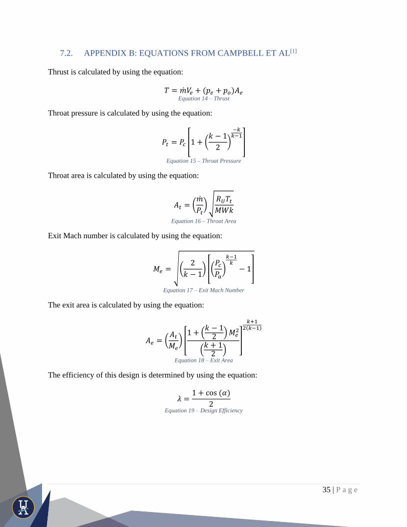
7.2. APPENDIX B: EQUATIONS FROM CAMPBELL ET AL[1]
Thrust is calculated by using the equation:
𝑇 = �̇�𝑉𝑒 + (𝑝𝑒 + 𝑝𝑜)𝐴𝑒 Equation 14 – Thrust
Throat pressure is calculated by using the equation:
𝑃𝑡 = 𝑃𝑐 [1 + (𝑘 − 1
2)
−𝑘𝑘−1
]
Equation 15 – Throat Pressure
Throat area is calculated by using the equation:
𝐴𝑡 = (�̇�
𝑃𝑡)√
𝑅𝑈𝑇𝑡𝑀𝑊𝑘
Equation 16 – Throat Area
Exit Mach number is calculated by using the equation:
𝑀𝑒 = √(2
𝑘 − 1) [(
𝑃𝑐𝑃𝑎)
𝑘−1𝑘
− 1]
Equation 17 – Exit Mach Number
The exit area is calculated by using the equation:
𝐴𝑒 = (𝐴𝑡𝑀𝑒
) [1 + (
𝑘 − 12 )𝑀𝑒
2
(𝑘 + 12 )
]
𝑘+12(𝑘−1)
Equation 18 – Exit Area
The efficiency of this design is determined by using the equation:
𝜆 =1 + cos(𝛼)
2
Equation 19 – Design Efficiency

36 | P a g e
Characteristic length is determined by using the equation:
𝐿∗ =𝜁2 ∗ 𝑟0
2 ∗ (2
𝑘𝑐 + 1) ∗ (
𝑘𝑐 − 12 ∗ 𝑀𝑐
2)
(𝑘𝑐+1)2(𝑘𝑐−1)
∗ √𝑘𝑐 ∗ (𝑀𝑊𝑐) ∗ 𝑇𝐶𝑂
𝑘𝑐𝐶𝑝𝑐 ∗ 𝑃𝑐
∗ log(1 + 𝐵)
Equation 20 – Characteristic Length
The Mach number in the chamber is determined by using the equation:
𝑀𝑐 =1
𝐶
Equation 21 – Chamber Mach Number
Variable B is determined by using the equation:
𝐵 =𝐶𝑝𝑐(𝑇𝑐 − 𝑇𝑝)
𝐻𝑓
Equation 22 – Variable B for Characteristic Length Equation
Variable S is determined by using the equation:
𝑆 =𝑃𝑟𝑐2𝐵
Equation 23 – Variable S for 𝜁2
Prandtl number of the gases in the chamber is determined by using the equation:
𝑃𝑟𝑐 =4𝑘
9𝑘 − 5
Equation 24 – Prandtl Number for Chamber Gases
Stagnation temperature in the inlet is determined by using the equation:
𝑇𝑐0 = 𝑇𝑐 (1 +𝑘𝑐 − 1
2∗ 𝑀𝑐
2)
Equation 25 – Inlet Stagnation Temperature
ζ2 is determined by using the equation:
𝜁2 =𝑥0 + 0.3
2 + 𝑆
Equation 26 – 𝜁2 for Characteristic Length
The contraction ratio is determined by using the equation:
𝐶 =𝐴𝑐𝐴𝑡
Equation 27 – Contraction Ratio

37 | P a g e
Chamber volume can be determined by working back through the equation:
𝐿∗ =𝑉𝑐𝐴𝑡
Equation 28 – Used to Find Area of the Throat
The cross-sectional area for the injector ports can be determined by using the equation:
𝐴 =�̇�
𝐶𝑑√2𝜌(𝑃𝑡 − 𝑃𝑐)
Equation 29 – Injector Ports Cross-Sectional Area
The heat transfer coefficient can be determined by using the equation:
ℎ𝑔 = [0.026
𝐷𝑡0.2 (
𝜇0.2𝐶𝑝
𝑃𝑟0.6)𝑛𝑠
((𝑝𝑐)𝑛𝑠𝑔
𝑐∗)0.8
(𝐷𝑡
𝑅)0.1
] × (𝐴𝑡𝐴)0.9
𝜎
Equation 30 – Heat Transfer Coefficient
σ can be determined by using the equation:
𝜎 =1
[12
𝑇𝑤𝑔(𝑇𝑐)𝑛𝑠
(1 +𝛾 − 12 𝑀2) +
12]
0.68
[1 +𝛾 − 12 𝑀2]
0.12
Equation 31 – Solving for σ
Characteristic velocity can be determined by using the equation:
𝐶∗ =√𝑘𝑐𝑅𝑇𝑐
𝑘𝑐√ 2𝑘𝑐 + 1
𝑘𝑐+1𝑘𝑐−1
Equation 32 – Characteristic Velocity
The heat removed as the nitrous oxide vaporizes can be determined by using the equation:
∆𝑄 = 𝑚𝑣𝐻𝑣 Equation 33 – Heat Removed as Nitrous Oxide Vaporizes
The temperature change can be determined by using the equation:
∆𝑇 =−∆𝑄
𝑚𝑙𝑖𝑞𝑢𝑖𝑑𝐶𝑙𝑖𝑞𝑢𝑖𝑑
Equation 34 – Change in Temperature

38 | P a g e
Density can be determined by using the equation:
∆𝑃 =�̇�𝑙𝑖𝑞𝑢𝑖𝑑
2
2𝜌𝑙𝑖𝑞𝑢𝑖𝑑(
𝐾
(𝑁𝐴𝑖𝑛𝑗𝑒𝑐𝑡𝑜𝑟)2 −
1
𝐴𝑚𝑎𝑛𝑖𝑓𝑜𝑙𝑑2 )
Equation 35 – Density
Mass flow rate created by this change in pressure can be determined by using the equation:
�̇�𝑙𝑖𝑞𝑢𝑖𝑑 = √2𝜌𝑙𝑖𝑞𝑢𝑖𝑑∆𝑃
𝐷𝑙𝑜𝑠𝑠
Equation 36 – Mass Flow Rate
The approximated loss factor that accounts for boundary effects can be determined by using the
equation:
𝐷𝑙𝑜𝑠𝑠 =𝐾
(𝑁𝐴𝑖𝑛𝑗𝑒𝑐𝑡𝑜𝑟)2
Equation 37 – Loss Factor
The true mass of liquid after a given time can be determined by using the equation:
𝑚𝑙𝑖𝑞𝑢𝑖𝑑 =
(𝑉𝑡𝑎𝑛𝑘 −𝑚𝑡𝑜𝑡𝑎𝑙
𝜌𝑣𝑎𝑝𝑜𝑟)
(1
𝜌𝑙𝑖𝑞𝑢𝑖𝑑−
1𝑝𝑣𝑎𝑝𝑜𝑟
)
Equation 38 – True Mass of Liquid after a Given Time

39 | P a g e
8. REFERENCES
[1] Campbell, C., & Adkins, P. (2020). Design and Testing of a Low-Cost Bipropellant
Liquid Rocket Engine (pp. 1-47, Rep.). Akron, OH: The University of Akron College of
Engineering.
[2] Palacz, T. (2017). Nitrous Oxide Application for Low-Thrust and Low-Cost Liquid
Rocket Engine. 7TH EUROPEAN CONFERENCE FOR AERONAUTICS AND SPACE
SCIENCES (EUCASS).
[3] J.D. Lindbolm. Analysis of nitrous oxide as a propellant with selected fuels. Master’s
thesis, New Mexico Institute of Mining and Technology, 2013.
[4] Youngblood, S. H. (2015). Design and Testing of a Liquid Nitrous Oxide and Ethanol
Fueled Rocket Engine. New Mexico Institute of Mining and Technology.
[5] N/A. (2015). Rocket Propulsion Analysis 2.3 Standard [Software]
[6] Edwig, R. (n.d.). Vapor Pressurization (VaPak) Systems History, Concepts, and
Applications. Retrieved from
http://www.holderaerospace.com/downloads/Technical_Papers/VaPak Systems
Overview.pdf
[7] Heister, S., & Anderson, W. (2019). Rocket Propulsion. Cambridge University Press.
[8] No Name. (N.d.) O-ring Design Considerations. Marco Rubber. Retrieved from
https://www.marcorubber.com/o-ring-groove-design-considerations.htm
[9] National Fire Protection Association. (2018). NFPA 1127: Code for High Power
Rocketry. Retrieved from https://catalog.nfpa.org/NFPA-1127-Code-for-High-Power-
Rocketry-P1410.aspx?icid=D729
[10] National Association of Rocketry. (2012). High Power Rocket Safety Code. Retrieved
from https://www.nar.org/safety-information/high-power-rocket-safety-code/
[11] Tripoli Rocketry Association. (n.d.). Safety Code for High-Power Rocketry. Retrieved
from
http://www.tripoli.org/Portals/1/Documents/Safety%20Code/HighPowerSafetyCode%20-
%202017.pdf


![[Rocketry] Liquid rocket engine combustion stabilization devices](https://static.fdocuments.us/doc/165x107/551f5257497959335b8b4e12/rocketry-liquid-rocket-engine-combustion-stabilization-devices.jpg)