LIQUID PROPULSION SYSTEMS
70
LIQUID PROPULSION SYSTEMS
Transcript of LIQUID PROPULSION SYSTEMS

LIQUID PROPULSION SYSTEMS

CONTENTSI IntroductionII Rocket SystemIII Concepts & Design equationsIV Design Implements V Thrust Chamber & Combustion devicesVI Propellant Storage & Feed SystemsVII Control Systems & ValvesVIII Materials IX Integration & EngineeringX Test ProgrammeXI Pogo & SloshXII Flight Performance

SOUNDING ROCKETS
PSLV
THE FUTURE
GSLV
SLVASLV
Indian Space Research Organisation- LAUNCH VEHICLES -

GSLV

I INTRODUCTION
Space as we all know has always been charming to mankind and provide inspiration and imagination. It had its beginnings in fiction, the product of fertile human mind. In Indian epics, ‘Pushpaka Vimanam’ is widely referred. In 1865, Jules Verne, wrote about spaceship having minimum velocity to escape earth’s gravity. The transformation of fiction to fact was done by the scientific work of Copernicus, Keppler, Galileo and Newton.
Apart from Chinese in 970 AD, Tippu Sultan in India developed high performance rockets of 2.4 km range for effective use in the war against the British. But rational theory on propulsion was attributed to Konstantin Tsiolkowsky who devised the famous rocket equation in 1903.

- Herman Oberth proposed novel design aspects of
liquid propellant rockets in mid 1920s.
- Robert Goddard experimented with rockets in the
second half of 1920.
- Tsiolkowsky brought out the concept of multistage
rockets in1924.
- Werner Van Braun, developed functional liquid
propellant rockets burning liquid oxygen & alcohol
in A4 engine for V2 missiles in early 1940.
II ROCKET SYSTEM
- Popularly known use of the name ‘Rocket’ is a complex space transportation system capable of transcending the atmosphere and beyond into near earth space and deliver the ‘payload’ into defined orbit. Among the many subsystems of the rocket, propulsion system is the power plant which provides kinetic energy conversion. This is the backbone of the total system and therefore, the entire launcher is referred to as ‘rocket’ though many other subsystems are necessary for successful functioning.

They are the following.
1. Guidance & Control:In order to achieve the orbit, the trajectory of the vehicle has to be optimally shaped to reach the end condition / state vector in space and the guidance system works out this path in the three dimensional space. The steering of the vehicle along the desired path is performed by the vehicle attitude control system which continuously orients the thrust vector as required to achieve the trajectory. Both guidance & control are closed loop systems autonomously managed by on board computers.

2. Navigation:
To arrive at the desired end condition, viz. payload
injection point in space, the vehicle has to keep
track of its current position and velocity vector &
attitude and the on board navigation system
provides & updates this input data to on board
computer on a continuous mode. These systems
are based on inertial sensors, viz. gyroscopes &
accelerometers, housed on the top of the vehicle
in equipment bay.

3. Staging & Separation:In general the rocket comprises multiple
propulsion system / stages. The inert stages
which have performed their functions i.e. fully
burnt out their propellants are jettisoned
sequentially as flight progresses through staging/
separation system which are essentially pyro/
explosive based systems that effect, clean,
disturbance free disconnection of hardware
as per on-board command.

The vehicle also has provision for premature
termination of flight through ground terminated
telecommand which activates certain onboard
explosives to break-up the rocket in flight if there
are gross deviation in flight path/behaviour
endangering people & property on ground.

4.Vehicle Avionics:
This comprises mainly electronic packages & systems
which implement
- Sequencing & pyro initiation functions
- Control command & feed back
- Telemetry of on-board requirements
- Tracking & telecommand during flight.
The avionics packages are concentrated in vehicle
equipment bay and are also distributed throughout the
vehicle inside interstage compartments

Success in space demands perfection. Many of the brilliant achievements made in this vast, austere environment seem almost miraculous. Behind each apparent miracle, however, stands the flawless performance of numerous highly complex systems. All are important. The failure of only one portion of a launch vehicle or spacecraft may cause failure of an entire mission. But the first to feel this awesome imperative for perfection are the propulsion systems, especially the engines. Unless they operate flawlessly first, none of the other systems will get a chance to perform in space. Perfection begins in the design of space hardware, with quality & reliability.

III CONCEPTS & DESIGN EQUATIONS
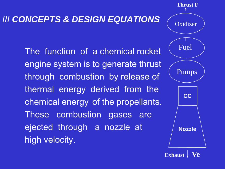
The function of a chemical rocketengine system is to generate thrustthrough combustion by release ofthermal energy derived from thechemical energy of the propellants.These combustion gases are ejected through a nozzle athigh velocity.
Oxidizer
Fuel
Pumps
Exhaust Ve
Thrust F
CC
Nozzle
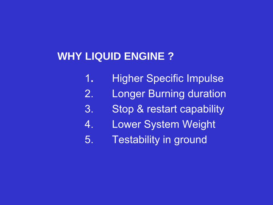
WHY LIQUID ENGINE ?
1. Higher Specific Impulse2. Longer Burning duration3. Stop & restart capability4. Lower System Weight5. Testability in ground

SELECTION OF LIQUID PROPELLANTS
• High Energy release per unit mass. Combined with low molecular weight of combustion products.
• Stable Combustion• High density to minimize size & weight of
propellant tanks• Effectiveness of thrust chamber cooling• High thermal & shock stability• Non corrosiveness & non toxicity• Cost & availability.

1. Ve dm = -m dv2. ΔV = Ve ln (mo / mi)
3. Thrust Coefficient Cf = F / At Pc
4. Characteristic exhaust velocityC* = At pc / m = C / Cf
5. Thrust F = Cf. At . pc = m* . Cf . C*6. Specific Impulse Isp
= Thrust /mass flow rate of propellant= F / W = F / m.g = C* . Cf / gα √ Tc / m

Propellant Chemistry & Performance CalculationsThe temperature Tc of the reaction in combustion chamber & the molecular weight M and the specific heat ratio γ of the exhaust are essential parameters in performance calculation. Various simplified assumptions such as frozen composition or the absence of shock waves & discontinuities may not be valid. Application of first principles for reliable estimation of the system performance is often necessary on the following simultaneous consideration.Chamber condition.
- Mass balance- Enthalpy balance (conservation of energy)- Pressure balance (Dalton’s law)- Chemical equilibrium ( minimization of Gibbs free
energy)

Rocket Performance:- Equation of state (Ideal gas law)
- Continuity equation (Conservation of mass)
- Conservation of momentum
- Conservation of energy ( first law of thermodynamics)
- Isentropic expansion (second law of thermodynamics)
Considerable numerical computations are thus
necessary. Sophisticated computer modelling &
simulation are to be done exclusively for accurate
prediction of performance.

IV DESIGN IMPLEMENTS
1. Thrust levels
2. Performance
3. Burn time
4. Propellant mixture ratio
5. Burnout mass.
6. Envelope/Size
7. Reliability
8. Cost
9. Schedule.

1. Thrust Level.- Lift off weight
- Minimum & maximum acceleration allowed.
- Single engine or multiple engine.
- Variable thrust.
2. Performance- Specific Impulse- Theoretical- Tested- Flight

3. Burn duration- Tank capacity- Pressurant storage- Nozzle cooling- Thrust build up- Shut down
4. Mixture Ratio- Stoichiometric ratio -(max. temp &
heat)- Exhaust velocity - (gas properties)- Optimum ratio - (Residence time in
combustion chamber; Chamber wall cooling)

5. Burnout Mass- Dry mass + residual propellants- Burn out mass- Wet mass – CG & MI- Wet gimbal mass.
6. Envelope/Size- Vehicle Structure- Handling- Servicing- Realisation- Expansion Ratio

7. Reliability- Unmanned/manned mission- Review of design, calculation & drawing- Paintaking execution of the above- Familiarizing with correct application of
accepted, prior design standards & procedures
- Written statements & instruction- Simplicity, Redundancy & Safety- Test condition vs. Flight condition- FMECA

8. Cost- Design Phase
- Engineering Phase
- Programme phase.
9. Schedule.
- Availability of subsystems
- Design Quality
- System Analysis
- Materials, Fabrication, Handling.

V THRUST CHAMBER & COMBUSTION DEVICESThrust chamber assembly undenially embodies the essence of rocket propulsion: the acceleration and ejection of matter, the reaction of which imparts the propulsive force to the vehicle.
The design goals are- maximum performance- stability & durability- minimum size, weight & cost.
Basic Elements are 1. Combustion process
- droplets spray- Evaporation by surrounding gas- Mixing & reaction- High speed diffusion- Stability of mixing process

1.IC engines
2.Gas turbines
3.Turbojets
4.Rockets
5.Detonative Combustion
Power Density of energy release of different propulsion devices
10-2 10-1 1 10 102 103 104
kW/cm3
Maruti
V2RD-170Zenith

2. Performance parameters
- Characteristic velocityC* = f (γ, R, Tc,)
- Thrust coefficient Cf
Cf = f (γ, ε, pa)
3.1 Configuration and LayoutThroat Area At = F / Cf. pc
Chamber volume Vc = m.V. tsCharacteristic length L* = Ve / At
= m.V.ts / Af

3.2 Shape: a) Long one:
gas flow pressure losses
b) Short one:
Vaporization zone – excessive
Combustion zone - inefficient

Conical nozzle Vs. Bell Nozzlec) Spherical: Less mass & cooling surface
Difficult to produce & poor performance
d) Cylindrical: Design Flexibility & easy to produceHeavy mass & more cooling surface
e) Conical Nozzle: non axial component of velocity leads to performance losses but easy to fabricate
f) Bell Nozzle: Shorter length & increased performance starting from fast expansion flow to uniform axial flow at exit

4. Cooling Techniques(i) Regenerative
cooling : widely used(ii) Dump Cooling : limited use(iii) Film Cooling : used in high heat
flux(iv) Transpiration cooling: special type(v) Ablative Cooling : mainly solid
motors, low Pc liquid system
(vi) Radiation Cooling : Used in nozzle extension/low heat flux.

5. Injector Design:- Combustion stability- Performance- Structural integrity- Hydraulic characteristics- Combustion chamber heat protection- Special requirements


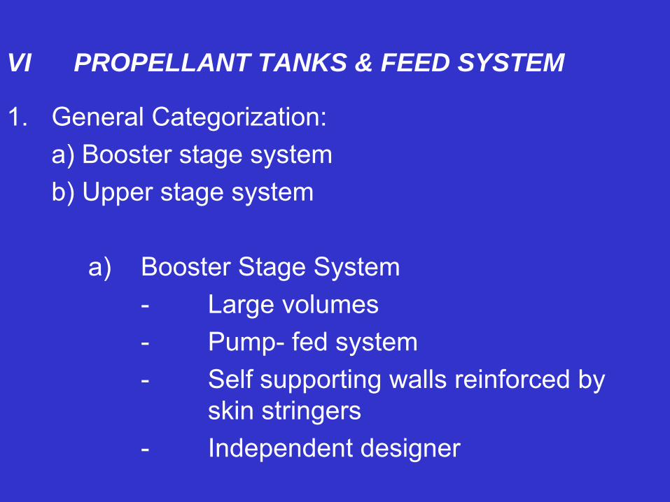
VI PROPELLANT TANKS & FEED SYSTEM
1. General Categorization:a) Booster stage systemb) Upper stage system
a) Booster Stage System- Large volumes- Pump- fed system- Self supporting walls reinforced by
skin stringers- Independent designer

b) Upper Stage System
- Smaller volumes- Pressure-fed system- Waffle / Isogrid walls- Most likely engine designer
2. Design consideration:- Propellant properties & Compatibility- Operating pressure & temperature- Thrust level from engines to vehicle- Manufacturing easiness.

3. Pressure – fed system
- Pressurant gas is used- Tank pressure higher than engine chamber
pressure- Flow rate governed by feed line resistance- For higher engine thrusts above 220 kN, not
effective(i) Stored gas system
- High pressure storage gas bottles are used- Pressure & flow rate are regulated for a
specified tank pressure- Helium gas is the most common gas

ii) Blow down system:
- No continuous feeding of gas.
- Pressurant gas expands in the ullage volume- Continuously decreasing the tank pressure- Not in common use
iii) Hot gas system:
- Gases produced in gas generator are used- System mass is less but highly complicated - Not in general use.

iv) Propellant evaporation system:- Propellants after cooling thrust chamber, are
vapourised - These vapours are fed back to tanks as
pressurant- Mainly used in cryogenics in fuel tanks.
4. Pump fed system- Used in high thrust engines requiring high
propellant flow rate- Larger pressurant flow rate & larger tank
volume make tank weight highly non-optimal

- Tank pressures are kept at low pressure levels just sufficient enough to meet NPSH requirements of pumps (0.4-0.5 MPa)
- Classified into either open or closed system depending on the way the power is supplied to turbine and how the energy of the working fluid is dumped from turbine exhaust.
- Open Cycle has 3 types & closed cycle has 2 types.
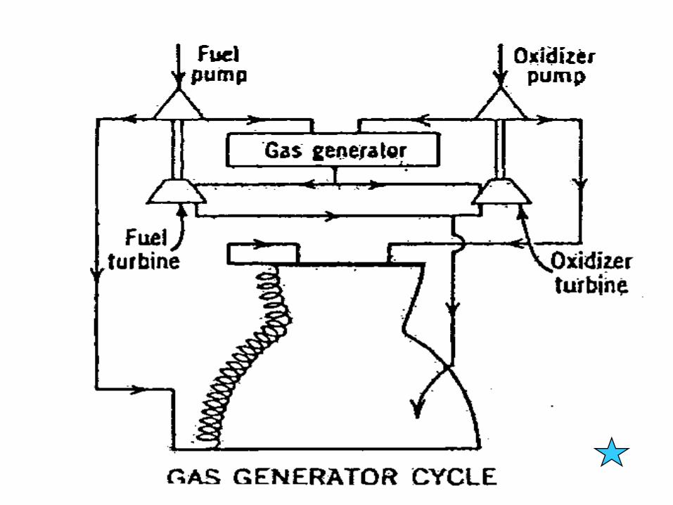
4.1 Open cycle: Turbine exhaust is directly discharged in a separate nozzle or into main thrust chamber nozzle at some point near exit where pressure levels are compatible.

(i) Gas Generator cycle
- Propellants are burnt partially in a separate combustion chamber called gas generator.
- The gaseous product is used to drive the turbine of the pump
(ii) Combustion tap off:- No need for a separate gas generator- Hot gas stream are bled from main thrust
chamber itself, at a point where the temperature is low enough for turbine operation.


(iii) Coolant Bleed cycle- No need for a separate gas generator- Hot gas stream to drive turbine is taken from
part of the vapour from cooling jacket of the
main thrust chamber
4.2 Closed cycle: Partially burnt turbine gas is
introduced into main thrust chamber for complete
burning. Very effective due to maximum energy
conversion of propellants and therefore a complex
system.


(i) Expander cycle:- Thrust chamber coolant liquid is evaporated into
hot gas; this is used to drive turbine and gets injected into combustion chamber
- Used in low thrust engines as the energy demands are not high
ii) Staged Combustion cycle:- The cooling liquid from main engine coolant
passage evaporates into hot gas; this is burnt in a pre-burner with small amount of oxidiser.
- The partially burnt combustion product is used to drive the turbine.
- After driving the turbine, the gases are injected into main thrust chamber for complete combustion.
- This enhances the specific impulse.


VI CONTROL SYSTEM & VALVES
A The propulsion system has the following control
systems:
1. Engine gimbal system
- Main engine gimbal
- Steering engine gimbal
2. Thrust regulation system
3. Mixture Ratio (O/F) control system.
4. Orientation & Stabilization system.

1. Engine Gimbal System:a) Main engine can be moved about its thrust axis by
providing 2 actuators at 90 deg. apart in order tosteer the rocket in the pre determined trajectory based on control system feed back from on-board computers.
b) Alternately 2 smaller engines can be configured at 180 deg. apart and keeping the main engine at fixed position. Each of these 2 steering engines is configured with 2 actuators each at 90 deg. apart so that combined action of these 2 engines can steer the rocket in the pre-determined trajectory based on closed loop control system feed back from on board computers.

2) Thrust control system:
It is essential to control the thrust of the engine by
careful regulation of the propellant mass flow rate.
There are number of techniques deployed
depending on the expertise available & system
optimization. This becomes all the more important in
upper stage systems where higher burn time and
velocities are involved.
3) Mixture ratio control system:
In ideal condition, mixture ratio is to be kept
constant; but the flight operating condition due to
various constraints, a control system is necessary to
ensure mixture ratio within a close tolerance for
optimum engine performance and complete
utilization of propellants loaded.

4) Orientation & Stabilization System:
The system generally employs an autonomous mini
thrust system based on
- Monopropellant system
- Bipropellant system
- Cold gas system.
This is required during non-propulsive phase of the
propulsion system to impart axial velocity prior to
ignition or interval between multi start or tumbling of
the upper stage away from satellite path.

VII CONTROL SYSTEM COMPONENTS/VALVES
Liquid systems are more complex and less reliable
mainly on account of large number of active
functional components/valves. Typical types are
listed below:- Propellant flow control valves- Electro pneumatic valves- Pneumatic valves- Electric motors for driving actuators of control
system
- Hydraulic system for actuating gimbal Engines- Pyro-initiated valves for critical systems.- Diaphragm type valves.- Vent valves for pressure control.- Safety relief valves for passive pressure control- Check valves- Filters.

VIII INTEGRATION & ENGINEERING
1. Engine Thrust frame2. Gimbal mount assemblies3. Interstages housing equipment packages4. Necessary cutouts for last minute checks5. Instrumentation scheme scheme6. Propellant Feed lines7. High pressure pump outlets8. Mounting on high pressure gas bottle9. Turbine exhaust, Hot gas ducts10.Repairs, replacement provision

IX MATERIALS1. Rocket engines must be built as light as possible
and propulsion system should be of maximum efficiency. This can be accomplished only through the most sophisticated use of all the available materials and advanced fabrication techniques.“Moderate increase in velocity and range can be achieved switching from ‘ordinary’ to high energy propellants, large increases are achievable by reduction of the dead weight fraction.Mathematically, velocity at burnout becomes infinite as empty weight tends to zero. It is therefore, sometimes possible for the structural design engineer to produce performance benefits greater than the propulsion engineer can produce”.

Examples of Materials used in LPSMaterial Type Application
1. Al. Alloys 2219, Propellant Tanks6061, Pump Housings7075
2. Austenite 321,316 Nozzle tubingStainless steel 347 ducts
3. Martensite 440C Bearings, BallsStainless steel Races
4. PH Stainless 174PH Valve partssteel 15.5 PH stem, poppets
5. Cobalt Alloys Stellite 21 Injection portsTurbine blades

Material Type Application6. Iron base 903, 909 Duct, Bellows
super alloys7. Titanium Alloys Ti-6Al-4V Gas bottles
Gimbal blocks8. Silica Composite Engine throat9. Carbon-carbon Composite Vanes, seals10. Alumina Protection Nozzles,
Zirconia coatings turbine blade11. Fluorocarbon KEL-F Gaskets
Polymer PTFE, FEP O rings, seals12. Elastomers Nitrile Sealants
Silicone gaskets

X TEST PROGRAMMETesting alone ensures validation of design
A There are different types of tests1. Development tests2. Qualification Tests3. Functional tests4. Acceptance tests5. Flight Tests.
B There are different levels of tests1. Components levels2. Subassembly levels3. Subsystem level4. System level.

C. There are different test conditions.
1. Simulated tests for flight environment like vibration, acoustics, thermal
2. Hot tests of engines in sea level.3. Hot test of engines in High Altitude condition
in vacuum chamber (100 m bar)
D. Stage Hot Test.

XI POGO & SLOSH
The longitudinal vibrations caused by an instability
arising from interaction of the vehicle structure with
propulsion system is called POGO. The vibration
begins spontaneously, intensifies, and then dies
away. These vibrations can overload vehicle
structure as well as lead to loss of propulsion
performance.

Two basic kinds of propulsion-system behaviour cause Pogo.
1. Engine coupled pogo – from the action of the tank - to - engine propellant feedlines and the engine itself. This leads to oscillations in engine thrust.
To overcome engine coupled POGO, close coupled accumulators in the engine feed line should be incorporated as close to the engine as possible.

2. Ullage coupled pogo – from the longitudinal vibration of the vehicle which causes ullage pressure oscillations. This forces the regulator to produce oscillatory flow of pressurant.
Ullage coupled instability can be overcome by alteration of regulator characteristics or additional accumulator in the feedline.

- Sloshing is the periodic motion of the free surface of the liquid in partially filled tank.
- It can be induced by changes in vehicle acceleration or in response to control & guidance commands.
- Free sloshing of liquids can produce lateral motions of the accelerating vehicle resulting in closed loop with control system, leading to instability.
- Such instability can lead to structural failures, propellant flow disturbances, engine shutdown etc.
- Usually anti-slosh baffles are used to damp the liquid motion and prevent instability.

XII FLIGHT PERFORMANCEIn order to ensure a successful flight, the performance related activities are initiated years ahead. The activities are:- Ensuring correct data based on system
characteristics & validation tests.- Carrying out results of flight performance- Statistical analysis covering full boundary condition.- Large number of computer simulation.The main flight of few minutes duration will validate the years of effort in design, fabrication & testing. The first flight alone gives the real performance in the “space” environment. Extensive instrumentation of the rocket provides the necessary data on the performance of all the systems. Exhaustive analysis of the data is done for full understanding to ensure reliable performance.

PERFORMANCE OF TYPICAL LIQUID PROPULSION SYSTEMS
Sl.No Fuel - Oxidization Mixture Ratio
Combust. Temp.(K)
Specific Impulse (s)
1 UDMH - N204 2.6 3140 285
2UDMH 50% N204Hydrazine 50%
2.0 3090 290
3 MMH - N204 2.2 3110 2884 Kerosene - LOX 2.7 3425 3005 Ammonia - LOX 1.4 2815 2606 Ethyl alcohol - LOX 1.8 3135 2857 LH2 - LOX 5.0 2738 4408 LH2 - LF2 8.0 3594 4209 Ammonia - LF2 3.5 4285 360

PERFORMANCE DATA FOR LIQUID BOOSTER ENGINES
Engine RD-270 RD-253 LR-87-A55 VikingRocket N-1/UR-700 Proton Titan ArianeThrust SL kN 6272 1570 1913 678VAC kN 6713 1745 2347 725Mixture Ratio 2.67 2.88 1.91 1.7Chamber Pressure. (MPa) 26.6 15.7 5.83 5.8
Isp SL (s) 301 285 259 243Vac (s) 322 316 281 278
Cycle SC SC GG GG

GTO = 180x36000 kmINCLINATION = 19.3°
CRYO B/O
SEPARATION
4L40H BOOSTER BURNOUTL37.5H IGNITION
VEHICLE LIFT OFF
CRYO STAGE IGNITION
EQUATOR CROSSING
L37.5H BURNOUT &
GSLV F01 MISSION PROFILE
PAYLOAD FAIRING
S/C INJECTION
Cryo stage Ign.Time = 291.82sAltitude = 131.180 kmR.velocity = 4.967 km/sRange = 596 km
H.S Sep.Time = 227.24sAltitude = 115.03 kmR.velocity = 3.432 km/sRange = 332 km
4L40Hs Shut-offTime = 147.64sAltitude = 70.32 kmR.velocity = 2.390 km/sRange = 114 km
Vehicle lift-off
Cryo stage shut-off.Time = 998.48sAltitude = 201.55 kmR.velocity = 9.78 km/sRange = 5292 km
GTO = 180 X 36072 kmInclination = 19.29o
S/C Injection
Equator crossingTime = 922 s
TYPICAL MISSION PROFILE
0800 1600 2400 3200 4000 4800
56006400 km