Liquid Metal Corrosion of 316L, Fe3AI, and FeCrSi in...
10
Liquid Metal Corrosion of 316L, Fe3AI, and FeCrSi in Molten Zn-AI Baths XINGBO LIU, EVER BARBERO, lING XU, MATTHEW BURRIS, KEH-MINN CHANG, and VINOD SIKKA Corrosion tests of 316L and two intermetallic compounds Fe3AI and FeCrSi in industrial Galvanizing (Zn-0.18Al), GALFAN (Zn-5AI), GALVALUME (Zn-55AI), and Aluminizing (AI-8Si) baths and lab-scale static baths were conducted. In on-line tests in industrial hot-dip baths, 316L steel shows better corrosion resistance than Fe3AI in Galvanizing, GALFAN, and GALVALUME baths. The corrosion resistance of 316L and Fe3AI is similar in Aluminizing bath. In static tests, FeCrSi shows the' best corrosion resistance in pure Zn, and AI-8Si baths. The corrosion resistance of 316L is better than that of Fe3Al. In Zn-5AI bath, 316L shows no thickness loss after the test. For the same bath composition, the corrosion rates of the alloys in industrial baths are higher than those in static baths. Bath temperature and chemical composition play important roles in corrosion and inter- metallic layer formation. Increasing bath temperature accelerates the corrosion process and changes the nature of intermetallic layers. A small amount of aluminum reduces the corrosion process by reducing the activity of Zn and forming inhibition layer. However, after aluminum content reaches the critical point, the dominant corrosion process changes from Zn-Fe reaction to AI-Fe reaction, and, consequently, the corrosion process accelerates by increasing aluminum content in the bath. I. INTRODUCTION THE coating of steel sheet by continuous hot dipping in a molten metal bath of zinc or in a ZnIAl melt is the most efficient and economical method of providing corrosion pro- tection, to most steel sheet compositions. Reliable perfor- mance of galvanizing pot hardware is essential to the productivity of 'l hot dip galvanizing line and the quality of coatings produced. As shown in Figure 1, the pot hardware in galvanizing bath includes the snout, sink roll, stabilizing rolls, and the bearings supporting them. The most frequent cause of galvanizing line stoppage is pot hardware problems that are related to one or more of the following three issues: (1) wear of bearings supporting the stabilizer roll and sink roll; (2) corrosion of the pot hardware in molten ZnIAl bath; and (3) the nucleation and growth of dross (intermetallic compound) on roll surfaces.[l] Corrosion of the hardware by molten ZnlAI alloys is one of the most important reasons to cause the downtime of production lines; thus, the corrosion resistance becomes the primary criterion for the selection of pot hardware materi- als. Besides corrosion resistance, there are other properties requirements for pot hardware materials, among which the resistance to intermetallic dross buildup on the surface for roll materials, wear resistance for bearing materials, and ductility are the most important ones. Since corrosion resis- tance is the.primary criterion for the pot-hardware materials XINGBO LID, Research Assistant Professor, EVER BARBERO, Professor and Department Chairman, lING XU, Ph.D. Student,MAITHEW BURRIS, Graduate Student, and KEH-MINN CHANG, Adjunct Profes- sor, are with the Department of Mechanical and Aerospace Engineering, West Virginia University, Morgantown, WV 26506. Contact e-mail: [email protected] VINOD SIKKA, Group Leader, is with the Metal and Ceramics Processing Group, Oak Ridge National Laboratories, Oak Ridge, TN 37831. Manuscript submitted November 25, 2003. METALLURGICAL AND MATERIALS TRANSACTIONS A and each candidate .material needs to show good corrosion resistance before other properties being investigated, other properties of the intermetallic materials were not investi- gated in this article. Corrosion behavior of the pot-hardware materials and coating have been studied; [2-5] however, many investigators show contrasting liquid zinc immersion results for the same alloys. [3,4,5] For instance, literature[3] concluded that aluminum in the molten zinc bath did not diffuse into , the WC-Co coating layer. However, the results in the lit- erature[4] showed that aluminum diffused as much as zinc diffused into the coating. The authors of the literature[4] pro- posed two possible reasons to explain the difference: (1) the study in literature[3] was carried out in high aluminum contents bath, i.e., 0.3 and 3.0 wt pct of aluminum; and (2) the sample in the literature [4] were immersed in zinc baths containing iron. 316L stainless steel is the most popular material for sta- bilizer and sink rolls in the industry and STELLITE* 6, a *STELLITE is a trademark of Deloro Stellite Inc., Belleville, ON, Canada. Co-based superalloy, is the most popular material for bear- ings supporting the sink and stabilizer rolls in hot-dipping bath. In recent years, improvement of pot-hardware materials is receiving significant attention and is largely focused on practical bases. Various types of Fe- and Co..;based super- alloys, ceramics, as well as WC coatings, have been devel- oped for this application. Intermetallic compounds, for their relatively low mater- ial cost, excellent corrosion resistance in some oxidation environments, and lower density, have also been extensively studied in the past decades. [6-9] The purpose of the present work is to investigate, by means of corrosion testing and microscopic examination, the effectiveness of Fe3AI-type intermetallic alloys as materials of construction for bath hard- ware in continuous lines. The corrosion behaviors of 316L VOLUME 36A, AUGUST 2005-2049
Transcript of Liquid Metal Corrosion of 316L, Fe3AI, and FeCrSi in...

Liquid Metal Corrosion of 316L, Fe3AI, and FeCrSi in MoltenZn-AI Baths
XINGBO LIU, EVER BARBERO, lING XU, MATTHEW BURRIS, KEH-MINN CHANG,and VINOD SIKKA
Corrosion tests of 316L and two intermetallic compounds Fe3AI and FeCrSi in industrial Galvanizing(Zn-0.18Al), GALFAN (Zn-5AI), GALVALUME (Zn-55AI), and Aluminizing (AI-8Si) baths andlab-scale static baths were conducted. In on-line tests in industrial hot-dip baths, 316L steel showsbetter corrosion resistance than Fe3AI in Galvanizing, GALFAN, and GALVALUME baths. Thecorrosion resistance of 316L and Fe3AI is similar in Aluminizing bath. In static tests, FeCrSi showsthe' best corrosion resistance in pure Zn, Zn-55AI~ and AI-8Si baths. The corrosion resistance of316L is better than that of Fe3Al. In Zn-5AI bath, 316L shows no thickness loss after the test. Forthe same bath composition, the corrosion rates of the alloys in industrial baths are higher than thosein static baths. Bath temperature and chemical composition play important roles in corrosion and intermetallic layer formation. Increasing bath temperature accelerates the corrosion process and changesthe nature of intermetallic layers. A small amount of aluminum reduces the corrosion process byreducing the activity of Zn and forming inhibition layer. However, after aluminum content reachesthe critical point, the dominant corrosion process changes from Zn-Fe reaction to AI-Fe reaction, and,consequently, the corrosion process accelerates by increasing aluminum content in the bath.
I. INTRODUCTION
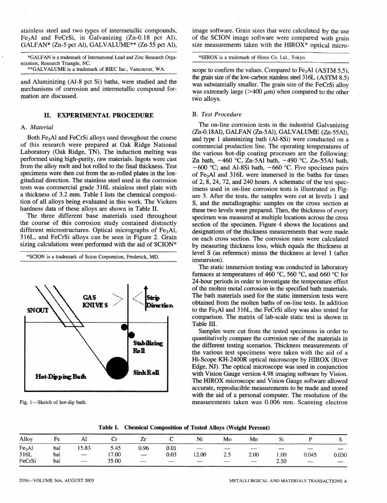
THE coating of steel sheet by continuous hot dipping ina molten metal bath of zinc or in a ZnIAl melt is the mostefficient and economical method of providing corrosion protection, to most steel sheet compositions. Reliable performance of galvanizing pot hardware is essential to theproductivity of 'l hot dip galvanizing line and the quality ofcoatings produced. As shown in Figure 1, the pot hardwarein galvanizing bath includes the snout, sink roll, stabilizingrolls, and the bearings supporting them. The most frequentcause of galvanizing line stoppage is pot hardware problemsthat are related to one or more of the following three issues:(1) wear of bearings supporting the stabilizer roll and sinkroll; (2) corrosion of the pot hardware in molten ZnIAl bath;and (3) the nucleation and growth of dross (intermetalliccompound) on roll surfaces.[l]
Corrosion of the hardware by molten ZnlAI alloys is oneof the most important reasons to cause the downtime ofproduction lines; thus, the corrosion resistance becomes theprimary criterion for the selection of pot hardware materials. Besides corrosion resistance, there are other propertiesrequirements for pot hardware materials, among which theresistance to intermetallic dross buildup on the surface forroll materials, wear resistance for bearing materials, andductility are the most important ones. Since corrosion resistance is the .primary criterion for the pot-hardware materials
XINGBO LID, Research Assistant Professor, EVER BARBERO,Professor and Department Chairman, lING XU, Ph.D. Student,MAITHEWBURRIS, Graduate Student, and KEH-MINN CHANG, Adjunct Professor, are with the Department of Mechanical and Aerospace Engineering,West Virginia University, Morgantown, WV 26506. Contact e-mail:[email protected] VINOD SIKKA, Group Leader, is with the Metaland Ceramics Processing Group, Oak Ridge National Laboratories, OakRidge, TN 37831.
Manuscript submitted November 25, 2003.
METALLURGICAL AND MATERIALS TRANSACTIONS A
and each candidate .material needs to show good corrosionresistance before other properties being investigated, otherproperties of the intermetallic materials were not investigated in this article. Corrosion behavior of the pot-hardwarematerials and coating have been studied; [2-5] however, manyinvestigators show contrasting liquid zinc immersion resultsfor the same alloys. [3,4,5] For instance, literature[3] concludedthat aluminum in the molten zinc bath did not diffuse into ,the WC-Co coating layer. However, the results in the literature[4] showed that aluminum diffused as much as zincdiffused into the coating. The authors of the literature[4] proposed two possible reasons to explain the difference: (1)the study in literature[3] was carried out in high aluminumcontents bath, i.e., 0.3 and 3.0 wt pct of aluminum; and(2) the sample in the literature[4] were immersed in zincbaths containing iron.
316L stainless steel is the most popular material for stabilizer and sink rolls in the industry and STELLITE* 6, a
*STELLITE is a trademark of Deloro Stellite Inc., Belleville, ON,Canada.
Co-based superalloy, is the most popular material for bearings supporting the sink and stabilizer rolls in hot-dippingbath. In recent years, improvement of pot-hardware materialsis receiving significant attention and is largely focused onpractical bases. Various types of Fe- and Co..;based superalloys, ceramics, as well as WC coatings, have been developed for this application.
Intermetallic compounds, for their relatively low material cost, excellent corrosion resistance in some oxidationenvironments, and lower density, have also been extensivelystudied in the past decades. [6-9] The purpose of the presentwork is to investigate, by means of corrosion testing andmicroscopic examination, the effectiveness of Fe3AI-typeintermetallic alloys as materials of construction for bath hardware in continuous lines. The corrosion behaviors of 316L
VOLUME 36A, AUGUST 2005-2049
stainless steel and two types of intermetallic .compounds,Fe3AI and FeCrSi, in Galvanizing (Zn-0.18 pct AI),GALFAN* (Zn-5 pct AI), GALVALUME** (Zn-55 pct AI),
image software. Grain sizes that were calculated by the useof the SCION image software were compared with graInsize measurements taken with the HIROX* optical micro..,
*GALFAN is a trademark of International Lead and Zinc Research Organization, Research Triangle, NC.
**GALVALUME is a trademark of BIEC Inc., Vancouver, WA.
and Aluminizing (AI-8 pct Si) baths, were studied and themechanisms of corrosion and intermetallic compound formation are discussed.
*HIROX is a trademark of Hirox Co. Ltd., Tokyo.
scope to confmn the values. Compared to Fe3Al (ASTM 5.5),the grain size of the low-carbon stainless steel 316L (ASTM 8.5)was substantially smaller. The grain size of the FeCrSi alloywas extremely large (>400 /-Lm) when compared to the othertwo alloys.
Fig. I-Sketch of hot-dip -bath.
*SCION is a trademark of Scion Corporation, Frederick, MD.
B. Test Procedure
The on-line corrosion tests in the industrial Galvanizing.(Zn-0.18Al), GALFAN (Zn-5AI), GALVALUME (Zn-55AI),and type 1 aluminizing bath (AI-8Si) were conducted on acommercial production line. The operating temperatures ofthe various hot-dip coating processes are the following:Zn bath, -460°C, Zn-5AI bath, -490°C, Zn-55AI bath,-600°C; and AI-8Si bath, -660°C. Five specimen pairsof Fe3AI and 316L were immersed in the baths for times'of 2, 8, 24, 72, and 240 hours. A schematic of the test specimens used in on-line corrosion tests is illustrated in Figure 3. After the tests, the samples were cut at levels 1 andS, and the metallographic samples on the cross section atthese two levels were prepared. Then, the thickness of everyspecimen was measured at multiple locations across the crosssection of the specimen. Figure 4 shows the locations anddesignations of the thickness measurements that were madeon each cross section. The corrosion rates were calculatedby measuring thickness loss, which equals the thickness atlevel S (as reference) minus the thickness at level 1 (afterimmersion).
The static immersion testing was conducted in laboratoryfurnaces at temperatures of 460°C, 560 °C, and 660°C for24-hour periods in order to investigate the temperature effectof the molten metal corrosion in the specified bath materials.The bath materials used for the static immersion tests wereobtained from the molten baths of on-line tests. In additionto the Fe3AI and 316L, the FeCrSi alloy was also tested forcomparison. The matrix of lab-scale static test is shown inTable III.
Samples were cut from the tested specimens in order toquantitatively compare the corrosion rate of the materials inthe different testing scenarios. Thickness measurements ofthe various test specimens were taken with the aid of aHi-Scope KH-2400R optical microscope by HIROX (RiverEdge, NJ). The optical microscope was used in conjunctionwith Vision Gauge version 4.98 imaging software by Vision.The HIROX microscope and Vision Gauge software allowedaccurate, reproducible measurements to be made and storedwith the aid of a personal computer. The resolution of themeasurements taken was 0.006 mm. Scanning electron
SinkRoB
GA.SKNIVES
II. EXPERIMENTAL PROCEDURE
A. Material
Both Fe3Al and FeCrSi alloys used throughout the courseof this research were prepared at Oak Ridge NationalLaboratory (Oak Ridge, TN). The inductionrnelting wasperformed using high-purity, raw materials. Ingots were castfrom the alloy melt and hot rolled to the final thickness. Testspecimens were then cut from the as-rolled plates in the longitudinal direction. The stainless steel used in'the corrosiontests was commercial grade 316L stainless steel plate witha.thickness of 3.2 mm. Table I lists the chemical composition of all alloys being evaluated in this work. The Vickershardness data of these alloys are shown in Table II.
The three different base materials used .throughout.the course of this corrosion study contained distinctlydifferent- microstructures. Optical micrographs of Fe3AI,316L, and FeCrSi alloys can be seen in Figure 2. Grainsizing calculations were performed with the aid of SCION*
Table I. Chemical Composition of Tested Alloys (Weight Percent)
Alloy Fe Al Cr Zr C Ni Mo Mn Si P S
Fe3A1 bal 15.83 5.45 0.96 0.01316L bal 17.00 0.03 12.00 2.5 2.00 1.00- 0.045 0.030FeCrSi bal 35.00 2.50
2050-VOLUME 36A, AUGUST 2005 METALLURGICAL AND MATERIALS TRANSACTIONS A
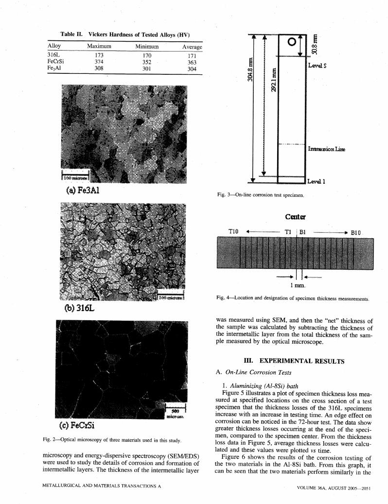
·Table II. Vickers ·Hardness of Tested Alloys (HV)
LevelS
L~l
~-. JIl. OAlv. "e
00 6($(Vl .....e.
N~
I
~ ~
--JWWri."
171363304
Average
170352301
Minimum
173374308
MaximumAlloy
316LFeCrSiFe3A1
(a) Fe3Al Fig. 3~On-line corrosion test specimen.
Center
Imm.
Fig._ 4-Location and designation of specimen thickness measurements.
(b) 316L
(c) FeCrSi
Fig. 2-0ptical microscopy of three materials used in this study.
microscopy and energy-dispersive spectroscopy (SEMlEDS)were used to study the details of corrosion and formation ofintermetallic layers. The thickness of the intermetallic layer
was measured using SEM, and then the "net" thickness ofthe sample was calculated by subtracting the thickness ofthe intermetallic layer from the total thickness of the sample measured by the optical microscope.
III. EXPERIMENTAL RESULTS
A. On-Line Corrosion Tests
1. Aluminizing (Al-8Si) bathFigure 5 illustrates a plot of specimen thickness loss mea'""
sured at specified locations on the cross section of a· testspecimen that the thickness losses of the 316L specimensincrease with an increase in testing time. An edge effect oncorrosion can be noticed in the 72-hour test. The data showgreater thickness losses occurring at the end of the specimen, compared to the specimen center. From the thicknessloss data in Figure 5, average thickness losses were calculated and these values were plotted vs time.
Figure 6 shows the results of the corrosion testing ofthe two materials in the AI-8Si bath. From this graph, itcan be seen that the two materials perform similarly in the
METALLURGICAL AND MATERIALS TRANSACTIONS A VOLUME 36A, AUGUST 2005-2051

Table III. Test Matrix of Static Corrosion Tests
316L Fe3A1 FeCrSi
Bath (Melting Point) 460°C 560 °C 660°C 460 °C 560°C" 660 °C 460°C 560 °C 660°C
AI-8Si (605°C) X X XZn-O.18AI (420°C) X X X X X X X X XZn-5AI (390°C) X X X X X X X X XZn-55AI (570°C) X X X
300200100
Fe3AI ... ,.--IJ. .
.6 ••.04
•••••••• 0.0 ••••• _ •• 316L~.iiiiio·" _ _
o
3.5" ...----------------
{3.0i 2.5~ 2.0•I 1.5I:I 1.0! 0.5
0.0
72 ht
24hr
3.5
3.0
.1 2.5
1{2.0o
.-1 "1.5=a "1.0~:a 0.5f-t
0.0o..:--1-.
Fig. 5-Thickness loss of 316L specimens in AI-8Si bath at 660°C. Time Chours)
Fig. 6-Thickness loss of 316L and Fe3Al specimens inAI-8Si bath at660°C.
Fig. 7-Thickness loss of 316L and Fe3AI specimens in GALFAN bathat 490°C.
."
3.5T"E 3.0-;2.5I.... 2.0
I 1.5i 1.0u:i! 0.5t-
0.0o
FeaJ.\1 4 iJ.," tJ. ,,
.. J"/
A:I 316L.,"41
m,i
100 200
Immersion Time Chours!300
3.5
(3Dii 2.5•~ 2.0•I 1.5
I 1.0i! 0.5
0.0e. .,.'..... '
o
.-."
316L
100 200Time Chourll)
.4
300
type 1 aluminizing bath. The iron aluminide specimen, however, seems to have a slightly lower resistance to corrosionthan the stainless steel alloy. The linear natqre of the thickness reduction rate (dy/dt), the slope of the fitted line, canalso be observed from the presente4data~ This linear trendseems to hold true for all on-line tests.
2. GALFAN (Zn-5Al) bathThough both materials seemed to perform similarly in the
Aluminizing (Ai-8Si) bath, the 316L specimens appeared tohave a better resistance to corrosion than the iron aluminide(Figure 7). Even after 240 hours in the bath, the 316L specimen showed little thickness loss. For the same time of 240hours, the Fe3Al specimens showed approximately 0.75 romof thickness reduction across the specimen cross section.The linear nature of the thickness reduction rate is evidentfrom this graph and the previous graphs. This linearity, however, contradicts the study by Lampe et ale [10] in which it
Fig. 8-Thickness loss of 316L and Fe3AI specimens in Galvanize bathat 460°C.
was stated that, in a zinc melt containing 4 pct aluminum,the time law for the corrosion of steel was found to be parabolic up to 500°C. Our study indicates a linear time lawat 490 °C in a zinc bath containing 5 pct aluminum.
3. Galvanizing (Zn-O.18Al) bathFigure 8 shows the performance of the two alloys in the
Galvanizing (Zn-0.18Al) bath. While 316L shows very little corrosion even after a time of 240 hours, Fe3AI alloyshows a substantial thickness loss. Considering that the initial iron aluminide specimens had a thickness of approximately 3.2 mID, a thickness loss of close to 2.5 mmdemonstrates the severe amount of corrosion that occurredwith this material in the zinc bath.
2052-VOLUME 36A, AUGUST 2005 METALLURGICAL AND MATERIALS TRANSACTIONS A

Fig. 9-Thickness loss of 316L and Fe3Al specimens in GALVALUMEbath at 600 ac.
4. GA.LVALUME (Zn-55Al) bathFigure 9 illustrates the performance of the stainless steel
and iron aluminide alloys in the on-line testing in the GALVALUME (Zn-55Al) bath. As in the Galvanizing bath, the316L stainless steel alloy shows a higher resistance to corrosion than the Fe3Al alloy. The stainless -steel alloy does showslightly more corrosion in the GALVALUME bath, whencompared to the GALFAN bath. Iron aluminide specimenshave a similar corrosion trend in the GALVALUME bath, tothose obtained from on-line testing in the GALFAN bath.
C. Intermetallic Layer Formation
Analysis of the interface layers formed during the corrosion testing was conducted with the aid of a scanningelectron microscope and the EDS capability of the 'microscope. Table V summarizes the phases identified upon theexamination of the corrosion specimens with SEM. Figure 10shows the backscattered electron image (BSI) of the interface layers formed by the immersion of 316L, Fe3AI, andFeCrSi specimens in the laboratory aluminizing bath at660°C for a period of 24 hours. As seen in Figure 9(a),the bright area on the left of the micrograph is the 316Lbase material. To the right of the matrix, a relatively thinalloy layer was observed. This alloy layer was approximately20 /-Lm in thickness and had a- uniform, continuous structure. From the EDS characterization of this thin alloy layer,the chemical composition was determined to be the 7]-Fe2AIsphase. This alloy layer is noted to form on the surface ofsteels that have been hot-dip coated in type 1 aluminizingbaths and was mentioned in various literature sources.[ll]A small amount of chromium that diffused from the matrixmaterial can also be seen in the EDS spectrum for the firstalloy layer. The next alloy layer contained less iron thanthe 7]-Fe2Als phase, and was identified as O-FeAI3. Withinthis second alloy layer, a crack can be seen that propagates within the brittle alloy layer, parallel to the edge ofthe original specimen. This second layer is much thickerthan the 7]-Fe2AIslayer, which formed adjacent to the 316Lmatrix. The cracks are believed to form during the coolingprocess, when the samples were taken out of the baths. Thedifferent coefficients of thermal expansion among variousintermetallic layers lead to internal stress. It is interestingthat the cracks formed within one thick intermetallic layerinstead of along with the phase interfaces, which means thatthe bonding between different layers is strong.
Figure 1O(b) reveals the interface layers formed by thecorrosion of the Fe3AI specimen in the AI-8Si bath. Thefirst alloy layer formed on the Fe3Al specimen had the samechemical composition as the first alloy layer formed onthe 316L specimen in this bath, and was therefore identified' as the 7]-Fe2AIs phase. Instead of forming a thin layerof the 7]-Fe2AIs phase, the iron aluminide specimen formeda thick layer of this phase. In Figure 1O(b), a crack can beseen in this alloy layer that propagates parallel to the specimen surface. The second alloy layer to form was identifiedas the O-FeA13phase, which is the same as the second alloylayer formed on the 316L sample. However, instead of form-
300100 200
TimeChoursl
B. Static Immersion Tests
Table IV lists measured thickness loss data from the static immersion tests. _All specimens were immerged in thebath at the specific temperatures for 24 hours. Because themelting point of the type 1 aluminizing mixture is approximately 605°C, the tests could not be run at temperaturesof 460 °c and 560°C.
It should be pointed out that the experimental FeCrSi alloyseems to outperform both 316L and Fe3AI in the Zn-0.18AI,Zn-55AI, and AI-8Si bath. This fact can be observed fromthe corrosion rates listed in Table IV. Within the AI-8Sibath, the 316L alloy showed the highest corrosion rate duringthe static immersion tests. Though the corrosion rate of theFeCrSi alloy was lower than the 316L and Fe3AI alloys,the performance of all three materials tested was very similarin the aluminizing bath. .
3.5
3.0
2.5
2.0
I 1.5
Ii 1.0:E 0.5 Fe3~1.. _. _.- ... -. ····316LJ- .•--A.." ;,.•.::.r:i. .. ------ c
0.0 1!I!Jr......-......;;;;;;;;;,.;----..........----.....--.a...----~----'
o
2.30 X 10- 1 2.99 X 10- 1 1.04 X 10° 3.61 X 10- 1 5.06 X 10- 1 2.54 X 10° 6.80 X 10⁻² 2.25 X 10- 1 1.00 x 10°
0.00 X 10° 3.00 x 10⁻³ 1.90 X 10- 2 4.00 X 10⁻³ 1.64 X 10° 2.55 X 10° 1.13 X 10- 1 1.17 X 10- 1 6.02 X 10°
1.57 X 10- 1NANA2.54 x 10°NANA3.94 X 10- 1NANA
Table IV. Average ~hickness Losses for Static Immersion Tests (mm)
316L Fe3A1 FeCrSi
460°C 560 °C 660°C 460 °C 560°C 660 °C 460°C 560 °C 660°C
NA NA 3.02 x 10- 1 NA NA 2.41 x 10- 1 NA NA 1.51 x 10- 1AI-8Si
(605°C)Zn-0.18AI
(420°C)Zn-5AI
(390°C)Zn-55AI
(570°C)
Bath (Melting _Point)
*NA: not available.
METALLURGICAL AND MATERIALS TRANSACTIONS A VOLUME 36A, AUGUST 2005-2053

Bath
Bath
Bath
Fe-Cr-AI
Fe2Als FeAI3
FeCrSi
316L Fe2AIs
Fe3AI
(a)-316L
Table V. Phase Identified from Corrosion Testing in Zn-AlHot..Dip Coating Baths for 24 Hours
Bath Test PhaseAlloy Types Temperature Identified
316L AI-8Si static 660°C YJ-Fe2AIs,O-FeAI3
Zn-0.18AI on-line 460°C Fe-AI-Zn phase(one layer)
Zn-5AI on-line 490°C YJ-Fe2AIs,O-FeA13
Zn-55AI on-line 600°C YJ-Fe2AIs,O-FeA13
Fe3AI AI-8Si static 660°C YJ-Fe2AIs,O-FeAI3
Zn-0.18AI on-line 460°C O-FeAI3
Zn-5AI on-line 490°C YJ-Fe2AIs,O-FeAI3
Zn-55AI on-line 600°C YJ-Fe2AIs,O-FeA13
FeCrSi AI-8Si static 660°C Fe-AI-Cr phase(one layer)
Zn-0.18AI on-line 460°C no phaseformation
Zn-5AI static 490°C Fe-AI-Cr phases(two layers)
Zn-55AI static 600°C Fe-AI-Cr phases(two layers)
ing a thick alloy layer as with the stainless steel sample,the Fe3Al formed a relatively thin alloy layer of FeAI3.
One distinct alloy layer was formed on the FeCrSi specimen (Figure ID(c)). The alloy layer that formed consisted ofa ternary phase of aluminum, iron, and chromium. The exactphase.that composed this alloy ·layer requires further identification. This layer contained a relatively high amount of aluminum, compared to the. amounts of chromium and iron.
The 316L and Fe3AI alloys formed similar Fe-AI phasesupon corrosion in Zn-55AI and AI-8Si baths. In both baths,the materials fonned alloy layers consisting of 1]-Fe2Al5 andO-FeAI3. The formation of these alloy layers may have contributed to the fact that during the on-line corrosion tests inthe Al-8Si and Zn-55Al, the·316L and Fe3Al alloys demonstrated similar corrosion rates.
In the galvanizing (Zn-O.18A1) bath, the 316L alloy formeda ternary alloy phase consisting of aluminum, iron, and zinc. Theiron aluminide formed a single alloy layer consisting of 8-FeA13,and the FeCrSi specimen formed no observable alloy layers.
Fig. 10-Interface layers formed from the static testing of the alloys in anAI-8Si at 660°C 'for 24 h (BSI).
Table VI. Corrosion Rates for On-Line CorrosionTests (cmlh)
IV. DISCUSSION
A. On-Line Corrosion vs Static Corrosion
Tables VI and VII show the corrosion rates of the alloysfor on-line corrosion and static corrosion tests. It can be seenthat the corrosion rate of the 316L specimen from on-linedynamic testing was found to be nearly 3 times higher thanthe value received in the static AI-8Si bath (Figure 6). Thestatic corrosion rate of Fe3A1 also shows a considerablereduction when compared to the corrosion rate received fromthe dynamic tests. The reasons for the reduction are illustrated as follows.
At first, the small volume of the static corrosion test bathbecomes saturated with dissolved elements from the specimen
Bath
Al-8SiZn-55AIZn-5AIZn-0.18AI
(c) - FeCtSi
Bath Temperature (OC)
690600
'490460
316L Fe3Al
1.78 X 10⁻³ 2.25 X 10⁻³
3.00 X 10⁻⁵ 1.65 X 10⁻⁴
2.00 X 10⁻⁶ 1.55 X 10⁻⁴
4.51 X 10⁻⁶ 4.96 X 10⁻⁴
2054-VOLUME 36A, AUGUST 2005 METALLURGICAL AND MATERIALS TRANSACTIONS A

Table VII. Corrosion Rates for Static Immersion Tests (cmlh)
Bath (Melting 316L Fe3AI FeCrSi
Point) 460°C 560 °C 660°C 460 °C 560°C 660 °C 460°C 560 °C 660°C
AI-8Si(605°C) NA NA 6.33 X 10⁻⁴ NA NA 5.06 X 10⁻⁴ NA NA 3.09 X 10⁻⁴
Zn-55AI(570°C) NA NA 8.23 X 10⁻⁴ NA NA 5.30 X 10⁻³ NA NA 3.22 X 10⁻⁴
Zn-5AI(390°C) 0 0 3.8 X 10⁻⁵ 1.49 X 10⁻⁵ 3.41 X 10⁻³ 5.33 X 10⁻³ 2.42 X 10⁻⁴ 2.42 X 10⁻⁴ 1.29 X 10⁻²
Pure Zn(420°C) 4.81 X 10⁻⁴ 6.2 X 10⁻⁴ 2.17 X 10⁻³ 7.59 X 10⁻⁴ 1.06 X 10⁻³ 5.30 X 10⁻³ 1.48 X 10⁻⁴ 4.7 X 10⁻⁴ 2.09' X 10-3
and this may have slowed the specimen's corrosion. Thedissolution of a solid metal in molten metal is described bythe Nemst-Shchukarev equation,[12] orBerthoud equationJ13]It may be written as
B. Aluminum Effect on Corrosion and Intermetallic LayerFormation
During the galvanizing process, the steel tends to reactwith molten zinc and form a series of Fe-Zn intermetalliccompounds layers, including 1'-Fe3ZnlO, B-FeZnIO' g-FeZnI3'
where C.is the instantaneous concentration of the dissolvedmetal in the melt, Cs is the saturation concentration, K isthe dissolution rate constant, A is the surface area of thesolid metal, and V is the volume of the melt. In the integratedform, Eq. [1] becomes (initial conditions: C = 0, t = 0)
C = Cs[l-exp (- K·A· t/V)] [2]
It is indicated from Eqs. [1] and [2] that if the volume ofmolten metal is small, the dissolution of solid metal willincrease C, and then the dissolution rate dCldt will decrease.On the contrary, if the volume of molten metal is large, as inindustrial hot-dip baths, the dissolution of solid metal willhave a minor effect on C; then, the dissolution rate dCldt willbe constant. Tunca et al. 's investigation[14] on corrosion ofMo, Nb, Cr, and Y in molten aluminum confirmed that insmall volume of molten aluminum, dCldt decreases with time.
Second, brittle intermetallic layers that form on the outsideof a corroded specimen would be more likely to spall offinto the melt in the moving industrial bath. The breaking offof these alloy layers would facilitate new growth and fastercorrosion in on-line testing. .
Finally, the flowing molten metal in the industrial bath hasa strong acceleration effect on the corrosion of the alloys. Asa matter of fact, during the past decades, the dynamic corrosionbehavior of the stainless steel in the molten lead-lithium alloysystem in the nuclear industry has been widely studied.[lS-20]It is generally concluded that (1) the corrosion behavior isvelocity dependent; (2) the flow pattern at various speeds, i.e.,laminar or turbulent flow, has a strong effect on the corrosionrate; and (3) the mechanisms of flow-iQduced corrosion maybe different at various flow speeds.. It can be mass-transportcontrolled, phase-transport controlled, erosion corrosion, orcavitation corrosion, according to the flow speed. These concepts can be applied to molten metal corrosion in the hot-dipindustry to explain faster corrosion rates in moving industrialbaths when compared to static lab-scale baths.
dC/dt = K·A/V·(Cs-C) [1]
etc.[21,22,23]. The morphology and thickness of each individuallayer are different, depending upon bath temperature andprocessing time. However, the bonding betWeen Fe-Zn intermetallic layers and steel substrate was not satisfactory. Aluminum is always added to the molten zinc bath to form theTJ-Fe2AIs inhibition layer, which can prevent diffusion orreaction between Fe and Zn and improve the bondingbetween the steel substrate and coating layer.[24]
The presence of aluminum in the bath changes the chemical environment and introduces new aluminum-content phasesinto the Fe-Zn alloy system. Therefore, in essence, bath chemistry management is the control of aluminum content. Aluminum also plays an important role in the corrosion of pothardware in molten hot-dipping baths. In pure Zn bath, thedominant corrosion reaction between the molten metal andthe alloys is Fe from the alloys reacting with Zn to form aseries Fe-Zn intermetallic compounds. Onishi et al.'[2S] showedthat the growth of the Fe-Zn phase in solid Fe-Zn diffusioncouples (annealed at 410°C for up to 100 hours) was controlled by the dominant one-sided diffusion of Zn through thephase layers toward the ,substrate Fe. When a small amountof aluminum was added into the Zn bath, the concentrationand activity of Zn was reduced; therefore, both the reactionrates ,between Fe and Zn and the diffusion-ofZn in the phaselayers were reduced. Yamaguchi and Hisamatsu[26;27] studiedthe reaction between molten Zn and steel substrate as, a function of dipping time, bath temperature, and aluminum content in the Zn alloy. They found that the amount of Fedissolved from the strip substantially decreased with increasing aluminum content, when the Al content was no more than0.2 wt pct. Tang[28] analyzed Fe dissolution in molten Zn-AIalloys' and found that the transient Fe solubility in the vicinityof the substrate/melt interface is much higher than the equilibrium value. He also concluded that aluminum atoms wouldsegregate to the substrate surface and form complexes, orso-called inhibition layer, with Fe atoms because of their highaffinity for Fe. This results in a decreasing Fe dissolution rate
. with increasing bath' Al content. The study by Tani et al. [3]
showed that as aluminum content increased in a molten zincbath, the diffusion depth of zinc into the WC-Co coating layerdecreased. It is certain that aluminum in a zinc bath suppresseszinc diffusion into the WC-Co coating layer. [4]
A small amount of Al can reduce the activity of Zn andform an inhibition layer, therefore reducing the corrosionrates of the steel substrate or pot-hardware materials. However, the Fe-Zn reaction is still the dominant process in thebath. After Al content reaches a critical value, the dominantprocess in the molten bath is changed from Fe-Zn reactionto Fe-AI reaction. Therefore, increasing aluminum content
METALLURGICAL AND MATERIALS TRANSACTIONS A VOLUME 36A, AUGUST 2005-2055
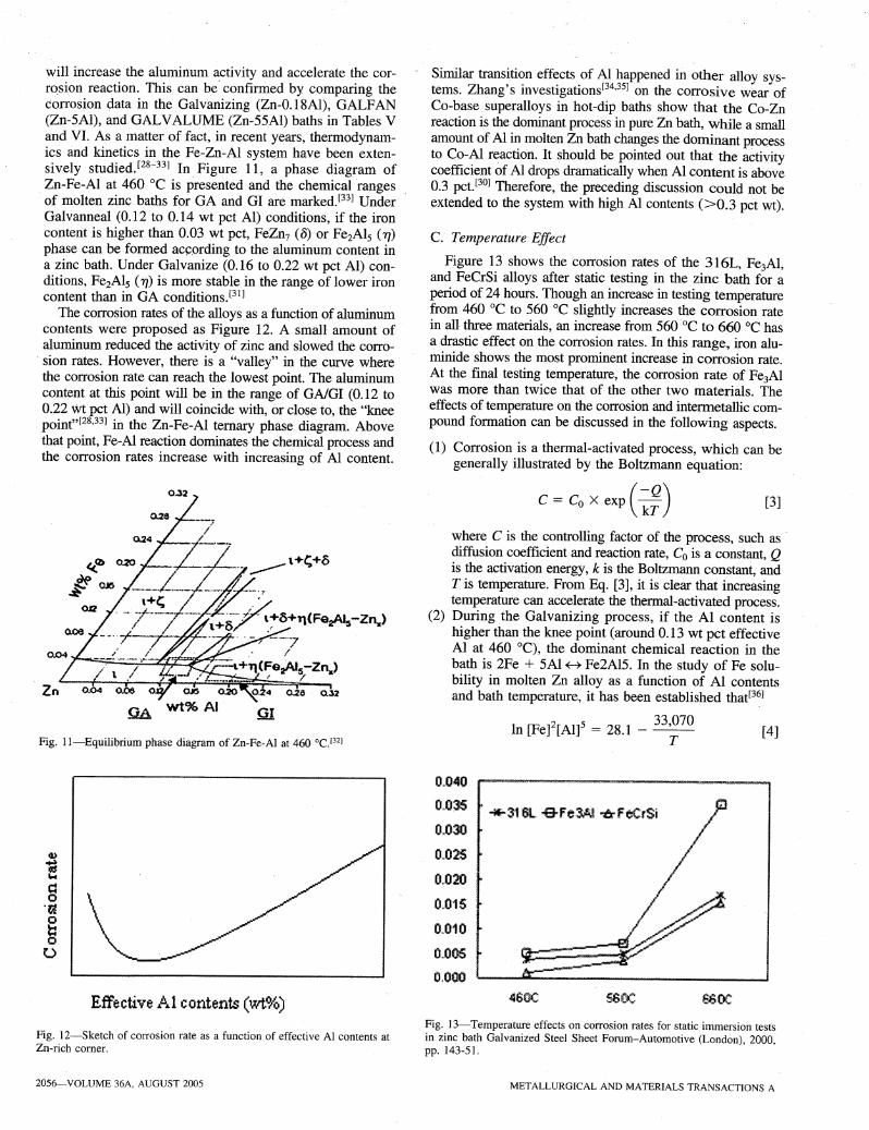
will increase the aluminum activity and accelerate the corr~sion reaction. This can be" confirmed by comparing thecorrosion data in the Galvanizing (Zn-0.18AI), GALFAN(Zn-~AI), and GALVALUME (Zn-55AI) baths in Tables Vand VI. As a matter of fact, in recent years, thermodynamics and kinetics in the Fe-Zn-AI system have been extensively studied. [28-33] In Figure 11, a phase diagram ofZn-Fe~AI at 460°C is presented and the chemical rangesof molten zinc baths for GA and GI are marked. [33] UnderGalvanneal (0.12 to 0.14 wt pet AI) conditions, if the ironcontent is higher than 0.03 wt pct, FeZn7 (B) or Fe2Al5 ('YJ)phase can be formed ac~.ording to the aluminum content ina zinc bath. Under Galvanize (0.16 to 0.22 wt pct AI) conditions, Fe2Al5 (TJ) is more stable· in the range of lower ironcontent than in GA conditions.[31]
The corrosion rates of the alloys. as a function of aluminumcontents were proposed as Figure 12. A small amount ofaluminum reduced the activity of zinc and slowed the corro-
. sion rates. However, there is a "valley" in the curve wherethe corrosion rate can reach the lowest point. The aluminumcontent at this point will be in the range of GAIGI (0.12 to0.22 wt pct AI) and will coincide with, or close to, the "kneepoint"[28,33J in the Zn-Fe-AI ternary phase diagram. Abovethat point, Fe-AI reaction dominates the chemical process andthe corrosion rates increase with increasing of Al content.
Fig. II-Equilibrium phase diagram of Zn-Fe-AI at 460 °CJ32]
Effective i~j,l contents (1Nt~.)
Fig. I2-Sketch of corrosion rate as a function of effective Al contents atZn-rich corner.
2056-VOLUME 36A, AUGUST 2005
Similar transition effects of Al happened in other alloy systems. Zhang's investigations[34,35J on the corrosive wear ofCo-base superalloys in hot-dip baths show that t.he Co-Znreaction is the dominant process in pure Zn bath, while a smallamount of Al in molten Zn bath changes the dominant processto Co-AI reaction. It should be pointed out that the activitycoefficient of Al drops dramatically when Al content is above0.3 pct. [30] Therefore, the preceding discussion could not beextended to the system with high Al contents (>0.3 pct wt).
C. Temperature Effect
Figure 13 shows the corrosion rates of the 316L, Fe3AI,and FeCrSi alloys after static testing in the zinc bath for aperiod of 24 hours. Though an increase in testing temperaturefrom 460°C to 560 °C slightly increases the corrosion ratein all three materials, an increase from 560°C to 660 °c hasa drastic effect on the corrosion rates. In this range, iron aluminide shows the most prominent increase in corrosion rate.At the final testing temperature, the corrosion rate of Fe3AIwas more than twice that of the other two materials. Theeffects of temperature on the corrosion and intennetallic compound formation can be discussed in the following aspects.
(1) Corrosion is a thermal-activated process, which can begenerally illustrated by the Boltzmann equation:
C = Co X exp ( ~;) [3]
where C is the controlling factor of the process, such as diffusion coefficient and reaction rate, Co is a constant, Qis the activation energy, k is the Boltzmann constant, andT is temperature. From Eq. [3], it is clear that increasingtemperature can accelerate the thermal-activated process.
(2) During the Galvanizing process, if the Al content ishigher than the knee point (around 0.13 wt pct effectiveAl at 460°C), the dominant chemical reaction in thebath is 2Fe + 5AI~ Fe2AI5. In the study of Fe solubility in molten Zn alloy as a function of Al contentsand bath temperature, it has been established that[36]
[4]
tt040
O~036
O~030
tL025
0.020
0.015
O~010
O~005
0.000
Fig. 13-Temperature effects on corrosion rates for static immersion testsin zinc bath Galvanized Steel Sheet Forum-Automotive (London), 2000,pp. 143-51.
METALLURGICAL AND MATERIALS TRANSACTIONS A
where [Fe] and [AI] are the Fe and Al solubility in themelt in weight percentage, and T is the absolute temperature. Therefore, changing temperature can change thesolubility of Fe and Al in the molten Zn·bath.For example, if temperature is changed from 460°C to. 500°C,the equilibrium solubility product [Fe]2[AI]5 increasesfrom 4.06 X 10⁻⁸ to 4.20 X 10⁻⁷. It should be pointedout that the increase of equilibrium solubility product withtemperature means the thermodynamic driving force ofcorrosion increases with temperature. However, the corrosion tests in this investigation were stopped before thesystem reached equilibrium. Therefore, the increase ofcorrosion rates with temperature rather reflects kinetics,i.e., faster diffusion at high temperature, than the increaseof thermodynamic driving force.
(3) Changing the temperature can change the Gibbs freeenergy of the phases and change the equilibrium phasetransformation in the alloy system. Verma's study[21,22]in pure Zn bath showed that at 455°C, the well-knownthree-phase structure, i.e., <5-FeZnIO' g-FeZnI3' and 11, wasformed. The thininnennost y-Fe3ZnIO layer did not form.In the temperature range 520°C to 550 DC, it was foundthat coatings at the lower end of the temperature rangehad a well-defmed g-FeZn13layer on the top of a 8-FeZnlOlayer. When the temperature was 560°C, there was athin layer of y-Fe3ZnlO between <5 and the steel substrate.
Similar to that of the Zn bath, changing temperature alsochanges the nature of phase equilibrium in aluminizing bath.
.Fotouchi found that at temperatures below 750°C, therewere two distinct intermetallic strata. [11] The outer thickerlayer was identified as a-Fe2SiAI8, while the inner, .muchthinner layer consisted of O-FeAI3. At temperatures higherthan approximately 750°C, the thinner FeAl3 was not identified, and the alloy layer consisted entirely of a-Fe2SiAls. [22]
v. CONCLUSIONS
Liquid metal corrosion of 316L stainless steel and twointermetallic compounds, Fe3AI and FeCrSi, were studiedby on-line and static corrosion tests in various Zn-AI baths.Several conclusions were drawn from this investigation andare as follows.
1. In on-line tests in industrial hot-dip baths, 316L steelshows better corrosion resistance than Fe3AI in Galvanizing (Zn-0.18AI), GALFAN (Zn-5AI), and GALVALUME (Zn-55AI) baths. The corrosion resistanceof 316L and Fe3AI are similar in type I aluminizing(AI-S5i) bath.
2. In static tests, FeCrSi shows the best corrosion resistancein pure Zn, Zn-55AI, and AI-8Si baths. The corrosionresistance of 316L is better than that of Fe3AI. In Zn-5AIbath, 316L shows no thickness loss after the test.
3. For the same bath composition, the corrosion rates.of thealloys in industrial baths are higher than those in staticbaths. The small scale of the static test bath is one ofthe reasons because the small volume of the static corrosion test bath becomes saturated with dissolved elements and slows the corrosion process. Another reasonis that the hydraulic flow in industrial baths acceleratesthe erosion-corrosion process
METALLURGICAL AND MATERIALS TRANSACTIONS A
4. Bath temperature and chemical composition play an important role in corrosion and intermetallic layer formation.Increasing bath temperature accelerates the corrosionprocess and changes the nature of intermetallic layers.
5. Aluminum content in the molten Zn bath plays a complexrole in the corrosion process. A small amount of aluminumreduces the corrosion process by reducing the activity ofZn and by forming an inhibition layer. However, afteraluminum content reaches the critical point, the dominantcorrosion process changes from Zn-Fe reaction to AI-Fereaction, and therefore, the corrosion process is acceleratedby increasing aluminum content in the bath.
ACKNOWLEDGMENTS
This work was supported by the United States Departmentof Energy under Contract No. DE-FC07-01IDI4042 andthe International Lead Zinc Research Organization (ILZRO)under Contract No. ZCO-15-2. The authors thank: Ms. Dianne'Berry for her kind support regarding the SEM analysis.
REFERENCES
1. F. Goodwin, K.-M. Chang, and V. Sikka: 94th Annual Meeting,Galvanizer Association, Algona, MI, 2002.
2. M. Brunnock, R Jones, G. Jenkins, and D. Llewellyn: Zinc-Based SteelCoating Systems, TMS, Warrendale, PA, 1998, pp. 51-62.
3. K. Tani and T. Tomita: Iron Steel Inst. Jpn., 1994, vol. 34, pp. 822-28.4. B. Seong, S. Hwang, M.C. Kim, and K.Y. Kim: Surface Coating
Techno/., 2001, vol. 138; pp. 101-10.5. M. Brunnock, R Jones, G. Jenkins, and D. Llewellyn: Ironmaking and
Steelmaking, 1997, vol. 24, pp. 40-46.6. A. Mignote, S. Frangini, A. La Barbera, and O. Tassa: Corr. Sci., 1998,
vol. 40, pp. 1331-47.7. V.K. Sikka: Processing, Properties, and Applications of Iron
Aluminides, TMS, Warrendale, PA, 1994, pp. 3-18.8. C.G. McKamey, lH. DeVan, P.F. Tortorelli, and V.K. Sikka: 1. Mater.
Res., 1991, vol. 6, pp. 1779-1805.9. C.T. Liu, C.G. McKamey, and E.H. Lee: Scripta Metall. Mater., 1990,
vol. 24, pp. 385-89.10. V. Lampe, H. Roos, and M. Svensson: Werkstoffe Korr., 1977,
vol. 28, pp. 226-32.11. R.W. Richards, R.D. Jones, P.D. Clements, and H. Clarke: Metallurgy
of Continuous Hot-Dip Aluminizing, M. Yan, Z. Fan: J. Mater. Sci.,2001, vol. 36, pp. 285-95.
12. V.1. Dybkov: J. Mater. Sci., 1990, vol. 25, pp. 3615-33.13. J.R. Weeks and D.H. Gurinsky: Liquid Metals and Solidification, ASM,
Materials Park, OH, 1958, pp. 106-61.14. N. Tunca, G.W. Delamore, and R.W. Smith: Metall. Trans. A, 1990,
vol. 21A, pp. 2919-28.15. J.1. Park, D.P. Butt, and C.A. Beard: Nucl. Eng. Des., 2000, vol. 196,
pp. 315-25.16. F. Balbaud-Celerier and F. Barbier: J. Nucl. Mater., 2001, vol. 289,
pp.227-42.17. E. Heitz: Corr. Eng.,1991, vol. 47, pp. 135-45.18. J. Weber: Br~ Corr. J., 1992, vol. 27, pp. 193-99.19. H.D. Borgstedt and H. Feurstein: J. Nucl. Mater., 1992, vols. 191-194,
pp.988-91.20. M.G. Baker, D.J. Siddons, and F. Barbier: J. Nucl. Mater., 1996,
vols. 233-237, pp. 1436-40.21. A.R.B. Verma and W.1. van Ooij: Surf Coating Technol., 1997,
vol. 89, pp. 132-42.22. A.R.B. Verma and W.J. van Ooij: Surf Coating Techno/., 1997,
vol. 89, pp. 143-50.23. C.E. Jordan and A.R. Marder: Metall. Mater. Trans. A, 1997, vol. 28A,
pp. 2683-94. .24. M.L. Hughes: J. Iron Steel Inst., 1950, Sept. p. 77.25. M. Onishi, Y. Wakamatsu, and H. Miura: Trans. JIM, 1974, vol. 15,
p. 331.
VOLUME 36A, AUGUST 2005-2057

26. H. Yamaguchi and Y. Hisamaysu: Tetsu-to-Hagane, 1973, vol. 59,pp. S553-54.
27. H. Yamaguchi and Y. Hisamaysu: Tetsu-to-Hagane, 1974, vol. 60,pp. 96-103.
28. N.-Y. Tang: Metall. Mater. Trans. B, 1999, vol. 30B, pp. 144-48.29. S. Chen and Y. Chang: CALPHAD, 1993, vol. 17, pp. 113-24.30. A. Costa e Silva et a!.: Z. Metallkd., 1999, vol. 90, pp. 38-43.31. N.-Y. Tang: J. Phase Equilibria, 2000, vol. 21, pp. 70-77.
2058-VOLUME 36A, AUGUST 2005
32. S. Yamaguchi and N. Fukatsu: Galvatech '95 Coni., ISS-AIME,Warrendale, PA, 1995, pp. 647-55.
33. N.-Y. Yang: Metal!. Mater. Trans. A, 1995, vol. 26A, pp. 1699-74.34. K". Zhang: Wear, 2003, vol. 255, pp. 545-55.35. K. Zhang and N.-Y. Tang: Metall. Mater. Trans. A, 2003, vol. 34A,
pp. 2387-96.36. N.-Y. Tang: Galvanised Steel Sheet Forum-Automotive, London, UK,
2000, pp. 143-51.
METALLURGICAL AND MATERIALS TRANSACTIONS A