Liquid Level Displacer Transmitter -...
16
Liquid Level Displacer Transmitter SIL Safety Manual for Model E3 Software v1.x This manual complements and is intended to be used with the E3 Modulevel ® Installation and Operating manual (Bulletin 48-635 dated October 2008 or later). Application The E3 Modulevel ® Liquid Level Displacer Transmitter can be applied in most process or storage vessels, bridles, bypass chambers, interfaces, sumps, and pits up to the unit pressure and temperature ratings. The E3 MODULEVEL can be used in liquids, clean or dirty, light hydrocarbons to heavy acids (SG=0.23 to 2.20) to meet the safety system requirements of IEC 61508. Benefits The E3 MODULEVEL provides the following benefits to your operation: • Suitable for use in environments up to SIL 2 (Safe Failure Fraction = 92.3%) as independently assessed (hardware assessment) by exida.com as per IEC 61508/61511-1. • Level ranges from 14 to 120+ inches (356 to 3048+ mm). • Process temperatures to +850° F (+454° C) for non-steam applications. • Process pressures to +5150 psi (+355 bar). • Continuous self-test with 22 mA or 3.6 mA fault indication fully compliant with NAMUR NE 43. • IS, XP, and Non-Incendive approvals. • Emission and immunity compliance to EN 61326. • Two-wire, loop-powered transmitter for level, interface, or density measurement. Functional Safety Manual
Transcript of Liquid Level Displacer Transmitter -...

Liquid Level
Displacer Transmitter
SIL Safety Manual for
Model E3Software v1.x
This manual complements and is intended to be used withthe E3 Modulevel® Installation and Operating manual(Bulletin 48-635 dated October 2008 or later).
Application
The E3 Modulevel® Liquid Level Displacer Transmittercan be applied in most process or storage vessels, bridles,bypass chambers, interfaces, sumps, and pits up to theunit pressure and temperature ratings. TheE3 MODULEVEL can be used in liquids, clean ordirty, light hydrocarbons to heavy acids (SG=0.23 to2.20) to meet the safety system requirements ofIEC 61508.
Benefits
The E3 MODULEVEL provides the following benefitsto your operation:
• Suitable for use in environments up to SIL 2 (SafeFailure Fraction = 92.3%) as independently assessed(hardware assessment) by exida.com as perIEC 61508/61511-1.
• Level ranges from 14 to 120+ inches(356 to 3048+ mm).
• Process temperatures to +850° F (+454° C) for non-steam applications.
• Process pressures to +5150 psi (+355 bar).
• Continuous self-test with 22 mA or 3.6 mA faultindication fully compliant with NAMUR NE 43.
• IS, XP, and Non-Incendive approvals.
• Emission and immunity compliance to EN 61326.
• Two-wire, loop-powered transmitter for level,interface, or density measurement.
Functional Safety Manual
48-650 E3 Modulevel Displacer Level Transmitter - SIL
Table of Contents
1.0 Introduction ...................................................................31.1 Product Description..................................................31.2 Theory of Operation.................................................31.3 Determining Safety Integrity Level (SIL) ..................4
2.0 Level Measuring System .................................................42.1 FOUNDATION fieldbus™ .............................................42.2 Applicable Models.....................................................42.3 Miscellaneous Electrical Considerations ....................5
2.3.1 Pollution Degree 2 .........................................52.3.2 Overvoltage ....................................................5
3.0 Mean Time To Repair (MTTR).....................................54.0 Supplementary Documentation......................................55.0 Instructions ....................................................................6
5.1 Systematic Limitations ..............................................65.1.1 Application.....................................................65.1.2 Environmental................................................6
5.2 Skill Level of Personnel .............................................65.3 Necessary Tools .........................................................75.4 Storage ......................................................................75.5 Installation ................................................................7
5.6 Configuration ...........................................................75.6.1 General...........................................................75.6.2 Write Protecting / Locking .............................75.6.3 Write Enabling / Unlocking ...........................8
5.7 Site Acceptance Testing .............................................85.8 Recording results.......................................................85.9 Maintenance .............................................................8
5.9.1 Diagnostics.....................................................85.9.2 Troubleshooting .............................................8
6.0 Recurrent Function Tests ...............................................96.1 Proof Testing .............................................................9
6.1.1 Introduction...................................................96.1.2 Interval...........................................................96.1.3 Recording Results...........................................96.1.4 Proof Test Procedure.......................................9
7.0 Appendices ...................................................................117.1 FMEDA Report Management Summary ................117.2 Specific Model E3 values.........................................137.3 PFD graph ..............................................................137.4 Report- Lifetime of Critical components.................147.5 Configuration Data Sheet .......................................14
E3 Modulevel® Displacer Level TransmitterSIL 1/SIL 2 Versions

348-650 E3 Modulevel Displacer Level Transmitter - SIL
1.0 Introduction
1.1 Product Description
The E3 MODULEVEL is a loop-powered, two-wire,24 VDC level transmitter that uses simple buoyancy princi-ples in combination with a precision range spring and ahighly accurate LVDT (linear variable differential trans-former) to detect and convert liquid level changes into astable 4–20 mA output signal. The electronics are housed inan ergonomic, dual-compartment enclosure that is angledfor ease of wiring and calibration.
The E3 MODULEVEL has microprocessor-based electron-ics with HART compatible output, in addition to the stan-dard 4–20 mA output. The E3 MODULEVEL supportsthe FDT/DTM standard and a PACTware™ PC software package allows for additional configuration and trendingcapabilities.
The linkage between the level sensing element and outputelectronics provides a simple mechanical design and con-struction. The vertical in-line design of the transmitterresults in low instrument weight and simplified installation.The instrument comes in a variety of configurations andpressure ratings for varied applications.
1.2 Theory of Operation
The E3 MODULEVEL Displacer Level Transmitter relieson the principles of buoyancy to convert mechanical move-ment to an electronic output.
The movement of the range spring, as it compresses or elon-gates based on the volume of displacer submerged in theliquid, causes movement of a special LVDT core attached tothe spring. The LVDT technology converts the movementof the LVDT core within the LVDT to a stable 4–20 mAoutput signal. The position of the core, with respect to aprimary and two secondary windings, induces voltage ineach winding. The comparison of the induced voltageswithin the microprocessor of the E3 MODULEVEL resultsin very accurate level or interface level output.
The E3 MODULEVEL can, alternatively, be set up to trackthe changing density of a liquid over a known density rangeand convert that into a stable 4–20 mA output signal. As thedensity of the liquid changes, so does the mass of the liquiddisplaced by the displacer. This resulting change in buoyancyforce on the displacer causes movement of the LVDT coreneeded to convert the density change to the 4–20 mA signal.
4 48-650 E3 Modulevel Displacer Level Transmitter - SIL
1.3 Determining Safety Integrity Level (SIL)
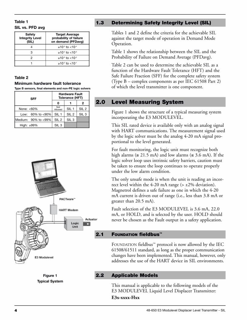
Tables 1 and 2 define the criteria for the achievable SILagainst the target mode of operation in Demand ModeOperation.
Table 1 shows the relationship between the SIL and theProbability of Failure on Demand Average (PFDavg).
Table 2 can be used to determine the achievable SIL as afunction of the Hardware Fault Tolerance (HFT) and theSafe Failure Fraction (SFF) for the complete safety system(Type B – complex components as per IEC 61508 Part 2)of which the level transmitter is one component.
2.0 Level Measuring System
Figure 1 shows the structure of a typical measuring systemincorporating the E3 MODULEVEL.
This SIL rated device is available only with an analog signalwith HART communications. The measurement signal usedby the logic solver must be the analog 4-20 mA signal pro-portional to the level generated.
For fault monitoring, the logic unit must recognize bothhigh alarms (≥ 21.5 mA) and low alarms (≤ 3.6 mA). If thelogic solver loop uses intrinsic safety barriers, caution mustbe taken to ensure the loop continues to operate properlyunder the low alarm condition.
The only unsafe mode is when the unit is reading an incor-rect level within the 4-20 mA range (> ±2% deviation).Magnetrol defines a safe failure as one in which the 4-20mA current is driven out of range (i.e., less than 3.8 mA orgreater than 20.5 mA).
Fault selection of the E3 MODULEVEL is 3.6 mA, 22.0mA, or HOLD, and is selected by the user. HOLD shouldnever be chosen as the Fault output in a safety application.
2.1 FOUNDATION fieldbus™
FOUNDATION fieldbus™ protocol is now allowed by the IEC61508/61511 standard, as long as the proper communicationchanges have been implemented. This manual, however, onlyaddresses the use of the HART device in SIL environments.
2.2 Applicable Models
This manual is applicable to the following models of theE3 MODULEVEL Liquid Level Displacer Transmitter:E3x-xxxx-Hxx
Figure 1
Typical System
Table 2
Minimum hardware fault toleranceType B sensors, final elements and non-PE logic solvers
SFF
Hardware FaultTolerance (HFT)
0 1 2
None: <60%Not
Allowed SIL 1 SIL 2
Low: 60% to <90% SIL 1 SIL 2 SIL 3
Medium: 90% to <99% SIL 2 SIL 3
High: ≥99% SIL 3
Table 1
SIL vs. PFD avg
SafetyIntegrity Level
(SIL)
Target Averageprobability of failureon demand (PFDavg)
4 ≥10-5 to <10-4
3 ≥10-4 to <10-3
2 ≥10-3 to <10-2
1 ≥10-2 to <10-1

548-650 E3 Modulevel Displacer Level Transmitter - SIL
2.3 Miscellaneous Electrical Considerations
2.3.1 Pollution Degree 2
The E3 MODULEVEL Level Displacer Transmitter isdesigned for use in Category II, Pollution Degree 2installations.
A nonconductive pollution of the sort where occasionally atemporary conductivity caused by condensation must beexpected. This is the usual pollution degree used forequipment being evaluated to IEC/EN 61010.
2.3.2 Overvoltage
The E3 MODULEVEL has overvoltage protection per CErequirements; this protection is to 1000 volts when consid-ering Hi-pot, Fast Transients, and Surge. Therefore, thereshould be no unsafe failure modes up to 1 KV.
Overvoltage Category II is a local level, covering appliances,portable equipment, etc., with smaller transient overvoltagesthan those characteristic of Overvoltage Category III. Thiscategory applies from the wall plug to the power supply iso-lation barrier (transformer). The typical plant environmentis Overvoltage Category II, so most equipment evaluated tothe requirements of IEC/EN 61010 are considered tobelong in that classification.
3.0 Mean Time To Repair (MTTR)
SIL determinations are based on a number of factors includingthe Mean Time To Repair (MTTR). The analysis for theE3 MODULEVEL Displacer Level Transmitter is based ona MTTR of 24 hours.
4.0 Supplementary Documentation
The E3 MODULEVEL Installation and Operating Manual(Bulletin 48-635) must be available for installation of themeasuring system.
The following Electronic Device Description File is requiredif HART is used:
Manufacturer Code 0x56Model E3 MODULEVEL Device ID OxE3, device revision 2DD revision 1
For device installations in a classified area, the relevantsafety instructions and electrical codes must be followed.
5.0 Instructions
5.1 Systematic Limitations
The following application and environmental limitationsmust be observed to avoid systematic failures.
5.1.1 Application
The E3 MODULEVEL transmitter should be located for easyaccess for service, configuration, and monitoring. There shouldbe sufficient headroom to allow installation and removal of thetransmitter head, and, in cases of tank top configuration, thedisplacer. Special precautions should be made to prevent expo-sure to corrosive atmosphere, excessive vibration, shock, orphysical damage. The E3 MODULEVEL should only be usedfor applications in which buildup of solid materials on thespring or in the enclosing tube is not an issue.
The operating temperature range for the transmitter electronicsis -40° to +176° F (-40° to +80° C). The operating temperaturerange for the digital display is -5° to +160° F (-20° to +70° C).
Caution: Operation of all buoyancy type level devices should bedone in such a way as to minimize the action of dynamicforces on the float or displacer sensing element. Goodpractice for reducing the likelihood of damage to the con-trol is to equalize pressure across the device very slowly.
5.1.2 Environmental
See Section 3.6.1 of the E3 MODULEVEL Installation andOperating Manual (Bulletin 48-635) for environmentallimitations.
5.2 Skill Level of Personnel
Personnel following the procedures of this safety manualshould have technical expertise equal to or greater than thatof a qualified instrument technician.
5.3 Necessary Tools
No special equipment or tools are required to installE3 MODULEVEL. The following items are recommended:• Wrenches, flange gaskets, and flange bolting
appropriate for process connection(s)• Flat-blade screwdriver• Level• 1/8" Allen wrench• 24 VDC power supply, 23 mA minimum• Digital multimeter• 250 to 450 ohm resistor for HART communication
6 48-650 E3 Modulevel Displacer Level Transmitter - SIL

5.4 Storage
The E3 MODULEVEL should be stored in its originalshipping box and not be subjected to temperatures outsidethe storage temperature range -50° to +185° F (-40° to+85° C), as shown in Section 3.6.1 of theE3 MODULEVEL Installation and Operating Manual(Bulletin 48-635) and associated specifications.
5.5 Installation
Refer to the E3 MODULEVEL Displacer Level TransmitterInstallation and Operating Manual (Bulletin 48-635) forthe proper installation instructions:
Section 1.0 provides QuickStart Installation instructionsand Section 2.0 provides Complete Installation instructions.
Section 2.6 provides menu selection items for configuringthe transmitter including operating parameters, display andkeypad, password protection, calibration defaults, and menuconfiguration based on the measurement type.
Section 2.7 provides configuration instructions if using HART.
This SIL evaluation has assumed that the customer will beable to acknowledge an over or under current condition viathe logic solver.
5.6 Configuration
5.6.1 General
The E3 MODULEVEL can be configured via the local dis-play, the HART compatible handheld communicator, or alaptop computer with PACTware.
5.6.2 Write Protecting / Locking
The E3 MODULEVEL transmitter is password protectedwith a numerical value between 0 (Default = 0 = Passworddisabled) and 255. After the password has been successfullyentered, an exclamation mark (!) appears as the last charac-ter on the first line of the display.
Refer to Section 2.6.3 of the E3 MODULEVEL Installationand Operating Manual (Bulletin 48-635) for informationon password protection.
748-650 E3 Modulevel Displacer Level Transmitter - SIL

5.6.3 Write Protecting / Locking
Ensure an exclamation mark (!) appears as the last characteron the first line of the display to confirm the password hasbeen accepted.
Refer to Section 2.6.3 of the E3 MODULEVEL Installationand Operating Manual (Bulletin 48-635) for informationon password protection.
When the alterations to the system are complete, ensure themenu has been locked with the password to prevent inad-vertent changes to the device.
5.7 Site Acceptance Testing
Complete a site acceptance test to ensure proper operationafter installation and configuration. This procedure is iden-tical to the Proof Test Procedure described in Section 6.1.4of this document.
5.8 Recording Results
Results of Site Acceptance Testing must be recorded forfuture reference.
5.9 Maintenance
The only maintenance required is the proof test.
• Report all failures to Magnetrol®.
• Firmware can only be upgraded by factory personnel.
5.9.1 Diagnostics
Internal diagnostic testing does a complete cycle 15 timesper second (1 every 67 ms). A message will appear and theoutput current will be driven to 3.6 or 22 mA (customerdependent) upon detection of a fault. Never specify HOLDas the fault signal in a safety application.
5.9.2 Troubleshooting
Refer to Section 3.3 of the E3 MODULEVEL Installationand Operating Manual (Bulletin 48-635) for troubleshoot-ing device errors. To assist in finding errors should theyoccur, at start-up complete the Configuration Data Sheetfound at the back of this manual, make a list of all deviceconfiguration parameters, including the password, andretain this information in a safe place.
8 48-650 E3 Modulevel Displacer Level Transmitter - SIL

6.0 Recurrent Function Tests
6.1 Proof Testing
6.1.1 Introduction
Following are the procedures used to detect DangerousUndetected (DU) failures. The procedure will detectapproximately 99% of possible DU failures in theE3 MODULEVEL transmitter.
6.1.2 Interval
To maintain the safety integrity level of a safety instrumentedsystem, it is imperative that the entire system be tested at regu-lar time intervals (TI in the appropriate standards). The SIL forthe E3 MODULEVEL is based on the assumption that theend user will carry out these tests and inspection at least onceper year. The onus is on the owner/operator to select the typeof inspection and the time period for these tests.
The system check must be carried out to prove that the safetyfunctions meet the IEC specification and result in the desiredresponse of the safety system as a whole.
6.1.3 Recording results
Record the results of the Proof Test for future reference.
6.1.4 Proof Test Procedure
A suggested proof test is described below. This test willdetect approximately 99% of possible DangerousUndetected (DU) failures in the E3 MODULEVEL.
1. Bypass the safety function and take appropriate action toavoid a false trip.
2. Use HART communications to retrieve any diagnostics andtake appropriate action.
3. Send a HART command to the transmitter to go to thehigh alarm current output and verify that the analog currentreaches that value. This tests for compliance voltage prob-lems such as a low loop power supply voltage or increasedwiring resistance. This also tests for other possible failures.
4. Send a HART command to the transmitter to go to the lowalarm current output and verify that the analog currentreaches that value. This tests for possible quiescent currentrelated failures.
948-650 E3 Modulevel Displacer Level Transmitter - SIL

5. Perform a five-point calibration check of the displacer andtransmitter over the full working range using process fluids.If the calibration check is performed by any means otherthan fluids acting on the displacer, this proof test will notdetect any failures of the displacer.
6. If the calibration is correct, the proof test is complete.Proceed to step 9. If the calibration is incorrect, remove thetransmitter from the process. Inspect for damage, buildup,or clogging. Clean if necessary.
7. If the calibration is off by more than 2%, contact the facto-ry for assistance. If the calibration is correct, the proof test iscomplete. Proceed to step 8.
8. Re-install the displacer and transmitter.
9. Remove the bypass and otherwise restore normal operation.
10 48-650 E3 Modulevel Displacer Level Transmitter - SIL

1148-650 E3 Modulevel Displacer Level Transmitter - SIL
7.0 Appendices
7.1 FMEDA Report: Exida Management Summary

12 48-650 E3 Modulevel Displacer Level Transmitter - SIL

1348-650 E3 Modulevel Displacer Level Transmitter - SIL
7.2 Specific Model E3 Values
7.3 PFD Graph
Proof Test Interval
(years)
PFD avg.
(SIL 2)
0 3.88 E-05
1 2.95 E-04
2 5.50 E-04
3 8.06 E-04
4 1.06 E-03
5 1.32 E-03
6 1.57 E-03
7 1.83 E-03
8 2.09 E-03
9 2.34 E-03
10 2.60 E-03
E3 Modulevel® Internal mount Remote mount
SIL SIL 2 SIL 2
HFT 0 0
SFF 92.3% 92.6%
PFDavg 2.95 E-04 2.95 E-04
Proof Test Interval Annually(refer to table below forother periods)
Annually(refer to table below forother periods)
Specific Model E3
14 48-650 E3 Modulevel Displacer Level Transmitter - SIL
7.4 Report: Lifetime of Critical Components
According to Section 7.4 of IEC 61508-2, a useful lifetime,based on experience, should be assumed.
Although a constant failure rate is assumed by the probabilisticestimation method, this only applies provided that the usefullifetime of components is not exceeded. Beyond their usefullifetime, the result of the probabilistic calculation method istherefore meaningless, as the probability of failure significantlyincreases with time. The useful lifetime is highly dependent onthe subsystem itself and its operating conditions.
This assumption of a constant failure rate is based on thebathtub curve. Therefore it is obvious that the PFDavgcalculation is only valid for components that have thisconstant domain and that the validity of the calculation islimited to the useful lifetime of each component.
As there are no aluminum electrolytic or tantalum elec-trolytic capacitors used, there are no electrical componentsthat limit the useful lifetime of the system.
Based on general field failure data, a useful life period ofapproximately 15 years is expected for the E3 MODULEVELLiquid Level Displacer Transmitter.
When plant experience indicates a shorter useful lifetime thanindicated, a number based on plant experience should be used.
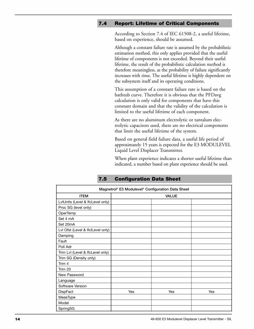
7.5 Configuration Data Sheet
Magnetrol® E3 Modulevel® Configuration Data Sheet
ITEM VALUE
LvlUnits (Level & lfcLevel only)
Proc SG (level only)
OperTemp
Set 4 mA
Set 20mA
Lvl Ofst (Level & lfclLevel only)
Damping
Fault
Poll Adr
Trim Lvl (Level & lfcLevel only)
Trim SG (Density only)
Trim 4
Trim 20
New Password
Language
Software Version
DispFact Yes Yes Yes
MeasType
Model
SpringSG

1548-650 E3 Modulevel Displacer Level Transmitter - SIL
ITEM VALUE
SprgRate
SprgMatl
TempLimt
Length
Diameter
Weight
Lower SG (lfc Level Only)
Upper SG (lfc Level Only)
CalSelct Factory Factory Factory
AdjSnrLo
AdjSnrHi
Conv Fct
Scl Ofst
LVDT%
Chan 0
Chan 1
NSPValue
ElecTemp
Max Temp
Min Temp
CalSelct User User User
AdjSnrLo
AdjSnrHi
Conv Fct
Scl Ofst
LVDT%
Chan 0
Chan 1
NSPValue
ElecTemp
Max Temp
Min Temp
Factory Cal Menu Enter Enter Enter
LVDT%
Calib SG
DrySensr
SnrCalLo
LvlCalLo
SnrCalHi
LvlCalHi
User Cal Menu Enter Enter Enter
LVDT%
DrySensr
SnrCalLo
LvlCalLo (Level & lfcLevel only)
Sg CalLo (Density only)
SnrCalHi
LvlCalHi
Sg CalHi (Density only)
7.5 Configuration Data Sheet (cont.)
BuLLETIN: 48-650.2
EFFECTIvE: December 2015
SuPERSEDES: June 2015
705 Enterprise Street • Aurora, Illinois 60504-8149 • 630-969-4000 • Fax [email protected] • www.magnetrol.com
Copyright © 2015 Magnetrol International, Incorporated. All rights reserved. Printed in the USA.
Service PolicyOwners of MAGNETROL may request the return of acontrol or any part of a control for complete rebuilding orreplacement. They will be rebuilt or replaced promptly.Controls returned under our service policy must bereturned by Prepaid transportation. MAGNETROL willrepair or replace the control at no cost to the purchaser (orowner) other than transportation if:
1. Returned within the warranty period; and2. The factory inspection finds the cause of the claim to
be covered under the warranty.
If the trouble is the result of conditions beyond our con-trol; or, is NOT covered by the warranty, there will becharges for labor and the parts required to rebuild orreplace the equipment.
In some cases it may be expedient to ship replacementparts; or, in extreme cases a complete new control, toreplace the original equipment before it is returned. If thisis desired, notify the factory of both the model and serialnumbers of the control to be replaced. In such cases, cred-it for the materials returned will be determined on thebasis of the applicability of our warranty.
No claims for misapplication, labor, direct or consequen-tial damage will be allowed.
Return Material ProcedureSo that we may efficiently process any materials that arereturned, it is essential that a “Return MaterialAuthorization” (RMA) number be obtained from thefactory prior to the material’s return. This is availablethrough MAGNETROL local representative or by con-tacting the factory. Please supply the following information:
1. Company Name2. Description of Material3. Serial Number4. Reason for Return5. Application
Any unit that was used in a process must be properlycleaned in accordance with OSHA standards, before it isreturned to the factory.
A Material Safety Data Sheet (MSDS) must accompanymaterial that was used in any media.
All shipments returned to the factory must be by prepaidtransportation.
All replacements will be shipped F.O.B. factory.
ASSuRED quALITy & SERvICE COST LESS
ReferencesIEC 61508-2: 2000 “Functional Safety ofElectrical/Electronic/Programmable Electronic SafetyRelated Systems”IEC 60654-1: 1993-02, second edition, “Industrial-process Measurement and Control Equipment –Operating Conditions – Part 1: Climatic Condition”
DisclaimerThe SIL values in this document are based on anFMEDA analysis using exida’s SILVER Tool.MAGNETROL accepts no liability whatsoever for theuse of these numbers or for the correctness of the stan-dards on which the general calculation methods arebased.