LIQUID-FUEL ROCKET ENGINESgramlich.net/projects/rocket/rocket.pdfLIQUID-FUEL ROCKET ENGINES...
40
LIQUID-FUEL ROCKET ENGINES
-
Upload
trinhnguyet -
Category
Documents
-
view
243 -
download
6
Transcript of LIQUID-FUEL ROCKET ENGINESgramlich.net/projects/rocket/rocket.pdfLIQUID-FUEL ROCKET ENGINES...
LIQUID-FUEL ROCKET ENGINES
Table of ContentsHOW to DESIGN, BUILD and TEST SMALL LIQUID-FUEL ROCKET ENGINES..............................1
ROCKETLAB / CHINA LAKE, CALIF.................................................................................................1NOTICE............................................................................................................................................1CONTENTS......................................................................................................................................1
HOW to DESIGN, BUILD and TEST SMALL LIQUID-FUEL ROCKET ENGINES..............................3ROCKETLAB / CHINA LAKE, CALIF.................................................................................................3
NOTICE............................................................................................................................................3FOREWORD.....................................................................................................................................3INTRODUCTION.............................................................................................................................3PROPELLANT CHOICE..................................................................................................................4PROPELLANT PROPERTIES.........................................................................................................7DESIGN EQUATIONS....................................................................................................................8EXAMPLE DESIGN CALCULATION.........................................................................................14FABRICATION..............................................................................................................................19TESTING EQUIPMENT................................................................................................................22TEST STAND.................................................................................................................................26SAFETY..........................................................................................................................................28ENGINE CHECK-OUT and CALIBRATION...............................................................................29IGNITION and OPERATION.........................................................................................................30BIBLIOGRAPHY...........................................................................................................................32LIST of SUPPLIERS.......................................................................................................................33CONVERSION FACTORS............................................................................................................36Additions and Corrections...............................................................................................................37Other Notices...................................................................................................................................37
LIQUID-FUEL ROCKET ENGINES
i
HOW to DESIGN, BUILD and TEST SMALLLIQUID-FUEL ROCKET ENGINES
ROCKETLAB / CHINA LAKE, CALIF.
NOTICE
Reprinted with permission.• ROCKETLAB cannot assume responsibility, in any manner whatsoever, for the use readers make ofthe information presented herein or the device resulting therefrom.
•
MIT, LCS, and the volunteers who have made this information available on the W3 likewise disclaimall responibility for whatever use readers make of this information. This document is provided on astrictly informational basis.
•
You can now download this entire book as a tarball. This can be decompressed with gzip and tar orwith WinZIP. The tarred file contains the exact same html and gif files that you see here. It's 288k.
•
Copyright 1967 by Leroy J. KrzyckiPrinted in the United States of AmericaFirst Printing: March 1967Second Printing: March 1971First WWW Edition: June 1996SBN 9600-1980-4
CONTENTS
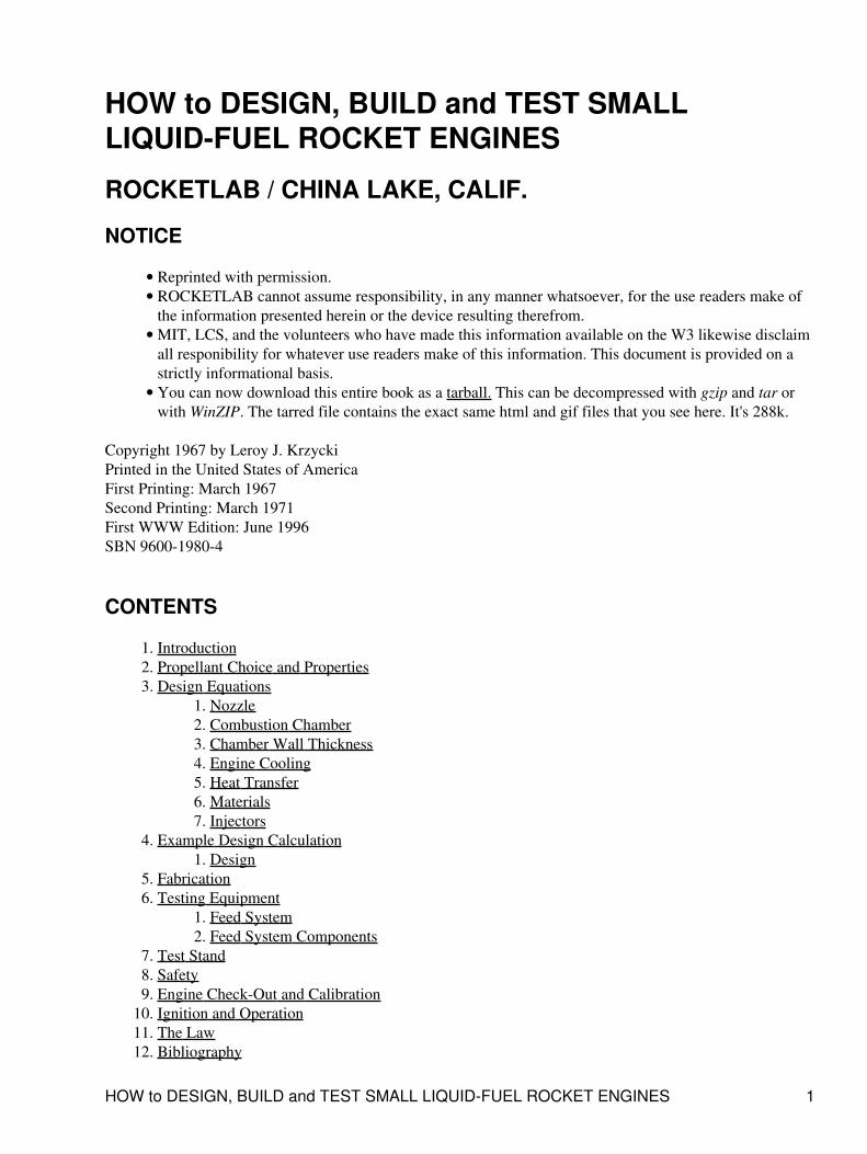
Introduction1. Propellant Choice and Properties2. Design Equations
Nozzle1. Combustion Chamber2. Chamber Wall Thickness3. Engine Cooling4. Heat Transfer5. Materials6. Injectors7.
3.
Example Design CalculationDesign1.
4.
Fabrication5. Testing Equipment
Feed System1. Feed System Components2.
6.
Test Stand7. Safety8. Engine Check-Out and Calibration9. Ignition and Operation10. The Law11. Bibliography12.
HOW to DESIGN, BUILD and TEST SMALL LIQUID-FUEL ROCKET ENGINES 1
List of Suppliers13. Conversion Factors14.
Additions and Corrections1. Other Notes2.
LIQUID-FUEL ROCKET ENGINES
CONTENTS 2
HOW to DESIGN, BUILD and TEST SMALLLIQUID-FUEL ROCKET ENGINES
ROCKETLAB / CHINA LAKE, CALIF.
NOTICE
ROCKETLAB cannot assume responsibility, in any manner whatsoever, for the use readers make of theinformation presented herein or the devices resulting therefrom.
FOREWORD
The rocket engine is a relatively simple device in which propellants are burned and the resulting high pressuregases are expanded through a specially shaped nozzle to produce thrust. Gas pressurized propellant tanks andsimple propellant flow controls make operation of a small liquid-fuel rocket engine about as simple asoperating an automobile engine. Why then do so many amateur rocket engines fail or cause injury? Thereason, usually and simply, is that the amateur is not accustomed to high pressure devices operating nearmaterial temperature limits. His normal everyday life is, instead, filled with devices and gadgets operating atlow pressures and at low thermal energy levels. With proper design, careful workmanship, and good testequipment, operated in a safe manner, the amateur can build small, liquid-fuel rocket engines which will havehours of safe operating life.
The puropse of this publication is to provide the serious amateur builder with design information, fabricationprocedures, test equipement requirements, and safe oeprating procedures for small liquid-fuel rocket engines.
INTRODUCTION
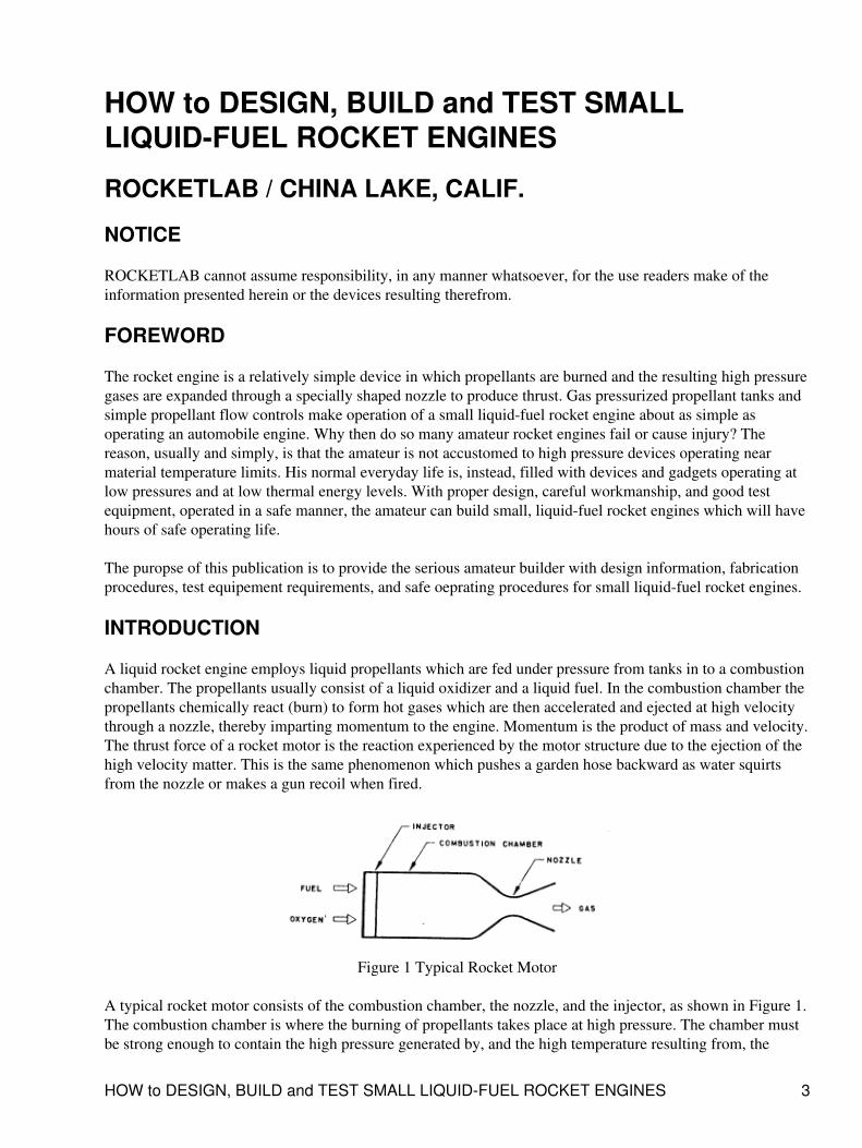
A liquid rocket engine employs liquid propellants which are fed under pressure from tanks in to a combustionchamber. The propellants usually consist of a liquid oxidizer and a liquid fuel. In the combustion chamber thepropellants chemically react (burn) to form hot gases which are then accelerated and ejected at high velocitythrough a nozzle, thereby imparting momentum to the engine. Momentum is the product of mass and velocity.The thrust force of a rocket motor is the reaction experienced by the motor structure due to the ejection of thehigh velocity matter. This is the same phenomenon which pushes a garden hose backward as water squirtsfrom the nozzle or makes a gun recoil when fired.
Figure 1 Typical Rocket Motor
A typical rocket motor consists of the combustion chamber, the nozzle, and the injector, as shown in Figure 1.The combustion chamber is where the burning of propellants takes place at high pressure. The chamber mustbe strong enough to contain the high pressure generated by, and the high temperature resulting from, the
HOW to DESIGN, BUILD and TEST SMALL LIQUID-FUEL ROCKET ENGINES 3
combustion process. Because of the high temperature and heat transfer, the chamber and nozzle are usuallycooled. The chamber must also be of sufficient length to ensure complete combustion before the gases enterthe nozzle.
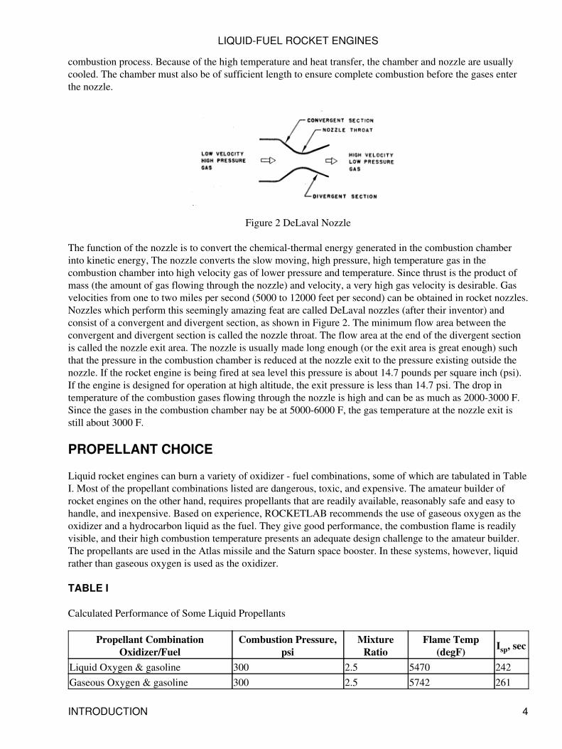
Figure 2 DeLaval Nozzle
The function of the nozzle is to convert the chemical-thermal energy generated in the combustion chamberinto kinetic energy, The nozzle converts the slow moving, high pressure, high temperature gas in thecombustion chamber into high velocity gas of lower pressure and temperature. Since thrust is the product ofmass (the amount of gas flowing through the nozzle) and velocity, a very high gas velocity is desirable. Gasvelocities from one to two miles per second (5000 to 12000 feet per second) can be obtained in rocket nozzles.Nozzles which perform this seemingly amazing feat are called DeLaval nozzles (after their inventor) andconsist of a convergent and divergent section, as shown in Figure 2. The minimum flow area between theconvergent and divergent section is called the nozzle throat. The flow area at the end of the divergent sectionis called the nozzle exit area. The nozzle is usually made long enough (or the exit area is great enough) suchthat the pressure in the combustion chamber is reduced at the nozzle exit to the pressure existing outside thenozzle. If the rocket engine is being fired at sea level this pressure is about 14.7 pounds per square inch (psi).If the engine is designed for operation at high altitude, the exit pressure is less than 14.7 psi. The drop intemperature of the combustion gases flowing through the nozzle is high and can be as much as 2000-3000 F.Since the gases in the combustion chamber nay be at 5000-6000 F, the gas temperature at the nozzle exit isstill about 3000 F.
PROPELLANT CHOICE
Liquid rocket engines can burn a variety of oxidizer - fuel combinations, some of which are tabulated in TableI. Most of the propellant combinations listed are dangerous, toxic, and expensive. The amateur builder ofrocket engines on the other hand, requires propellants that are readily available, reasonably safe and easy tohandle, and inexpensive. Based on experience, ROCKETLAB recommends the use of gaseous oxygen as theoxidizer and a hydrocarbon liquid as the fuel. They give good performance, the combustion flame is readilyvisible, and their high combustion temperature presents an adequate design challenge to the amateur builder.The propellants are used in the Atlas missile and the Saturn space booster. In these systems, however, liquidrather than gaseous oxygen is used as the oxidizer.
TABLE I
Calculated Performance of Some Liquid Propellants
Propellant CombinationOxidizer/Fuel
Combustion Pressure,psi
MixtureRatio
Flame Temp(degF) Isp, sec
Liquid Oxygen & gasoline 300 2.5 5470 242Gaseous Oxygen & gasoline 300 2.5 5742 261
LIQUID-FUEL ROCKET ENGINES
INTRODUCTION 4
Gaseous Oxygen & gasoline 500 2.5 5862 279Liquid Oxygen & JP-4 (jet fuel) 500 2.2 5880 255Liquid Oxygen & methyl alcohol 300 1.25 5180 238Gaseous Oxygen & methyl alcohol 300 1.2 5220 248Liquid Oxygen & hydrogen 500 3.5 4500 363Red fuming nitric acid & JP-4 500 4.1 5150 238Gaseous oxygen can be readily and inexpensively obtained in pressurized cylinders in almost any communitybecause of its use in oxy-acetylene welding. With reasonable precautions, to be detailed later, the gas (andcylinder) is safe to handle for rocket test stand use. Gas pressures are easily regulated with commercialregulators and gas flow rate is easily controlled with commercially available valves.
Hydrocarbon fuels, such as gasoline and alcohol, are readily available in any community. Safety precautionsare already known by most responsible individuals due to wide use of the fuels in internal combustion enginesfor automobiles and power equipment.
All subsequent sections of this publication will refer to, and assume, that the propellants to he used in amateurliquid-fuel rocket engines are gaseous oxygen and hydrocarbon fuel.
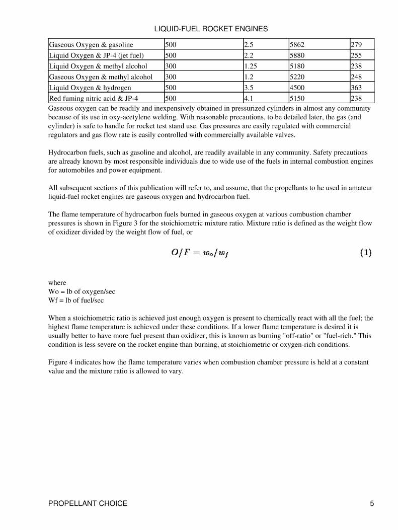
The flame temperature of hydrocarbon fuels burned in gaseous oxygen at various combustion chamberpressures is shown in Figure 3 for the stoichiometric mixture ratio. Mixture ratio is defined as the weight flowof oxidizer divided by the weight flow of fuel, or
whereWo = lb of oxygen/secWf = lb of fuel/sec
When a stoichiometric ratio is achieved just enough oxygen is present to chemically react with all the fuel; thehighest flame temperature is achieved under these conditions. If a lower flame temperature is desired it isusually better to have more fuel present than oxidizer; this is known as burning "off-ratio" or "fuel-rich." Thiscondition is less severe on the rocket engine than burning, at stoichiometric or oxygen-rich conditions.
Figure 4 indicates how the flame temperature varies when combustion chamber pressure is held at a constantvalue and the mixture ratio is allowed to vary.
LIQUID-FUEL ROCKET ENGINES
PROPELLANT CHOICE 5
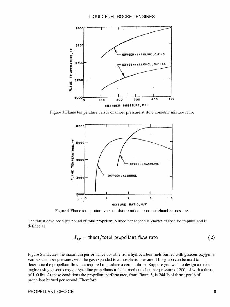
Figure 3 Flame temperature versus chamber pressure at stoichiometric mixture ratio.
Figure 4 Flame temperature versus mixture ratio at constant chamber pressure.
The thrust developed per pound of total propellant burned per second is known as specific impulse and isdefined as
Figure 5 indicates the maximum performance possible from hydrocarbon fuels burned with gaseous oxygen atvarious chamber pressures with the gas expanded to atmospheric pressure. This graph can be used todetermine the propellant flow rate required to produce a certain thrust. Suppose you wish to design a rocketengine using gaseous oxygen/gasoline propellants to be burned at a chamber pressure of 200 psi with a thrustof 100 lbs. At these conditions the propellant performance, from Figure 5, is 244 lb of thrust per lb ofpropellant burned per second. Therefore
LIQUID-FUEL ROCKET ENGINES
PROPELLANT CHOICE 6
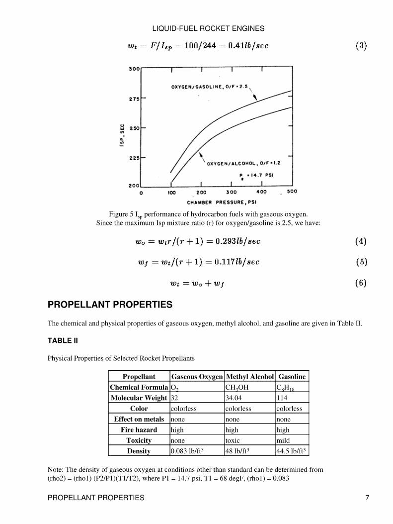
Figure 5 Isp performance of hydrocarbon fuels with gaseous oxygen.Since the maximum Isp mixture ratio (r) for oxygen/gasoline is 2.5, we have:
PROPELLANT PROPERTIES
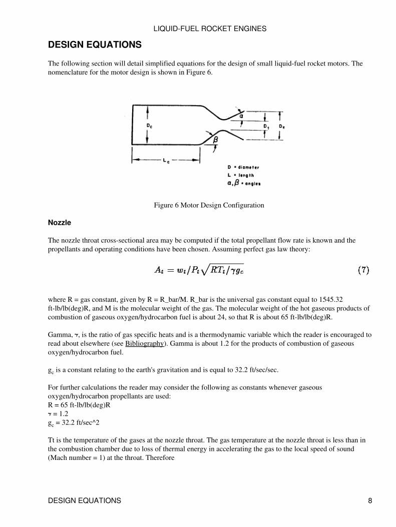
The chemical and physical properties of gaseous oxygen, methyl alcohol, and gasoline are given in Table II.
TABLE II
Physical Properties of Selected Rocket Propellants
Propellant Gaseous Oxygen Methyl Alcohol GasolineChemical Formula O2 CH3OH C8H18
Molecular Weight 32 34.04 114Color colorless colorless colorless
Effect on metals none none noneFire hazard high high high
Toxicity none toxic mildDensity 0.083 lb/ft3 48 lb/ft3 44.5 lb/ft3
Note: The density of gaseous oxygen at conditions other than standard can be determined from(rho2) = (rho1) (P2/P1)(T1/T2), where P1 = 14.7 psi, T1 = 68 degF, (rho1) = 0.083
LIQUID-FUEL ROCKET ENGINES
PROPELLANT PROPERTIES 7
DESIGN EQUATIONS
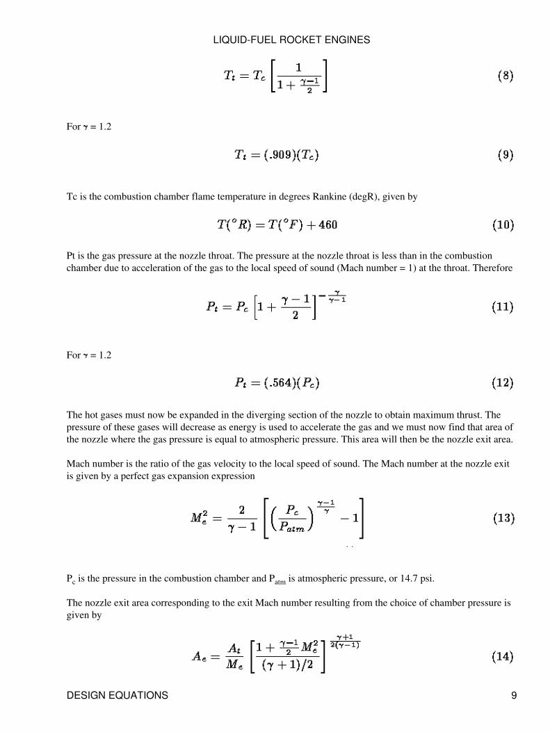
The following section will detail simplified equations for the design of small liquid-fuel rocket motors. Thenomenclature for the motor design is shown in Figure 6.
Figure 6 Motor Design Configuration
Nozzle
The nozzle throat cross-sectional area may be computed if the total propellant flow rate is known and thepropellants and operating conditions have been chosen. Assuming perfect gas law theory:
where R = gas constant, given by R = R_bar/M. R_bar is the universal gas constant equal to 1545.32ft-lb/lb(deg)R, and M is the molecular weight of the gas. The molecular weight of the hot gaseous products ofcombustion of gaseous oxygen/hydrocarbon fuel is about 24, so that R is about 65 ft-lb/lb(deg)R.
Gamma, , is the ratio of gas specific heats and is a thermodynamic variable which the reader is encouraged toread about elsewhere (see Bibliography). Gamma is about 1.2 for the products of combustion of gaseousoxygen/hydrocarbon fuel.
gc is a constant relating to the earth's gravitation and is equal to 32.2 ft/sec/sec.
For further calculations the reader may consider the following as constants whenever gaseousoxygen/hydrocarbon propellants are used:R = 65 ft-lb/lb(deg)R = 1.2
gc = 32.2 ft/sec^2
Tt is the temperature of the gases at the nozzle throat. The gas temperature at the nozzle throat is less than inthe combustion chamber due to loss of thermal energy in accelerating the gas to the local speed of sound(Mach number = 1) at the throat. Therefore
LIQUID-FUEL ROCKET ENGINES
DESIGN EQUATIONS 8
For = 1.2
Tc is the combustion chamber flame temperature in degrees Rankine (degR), given by
Pt is the gas pressure at the nozzle throat. The pressure at the nozzle throat is less than in the combustionchamber due to acceleration of the gas to the local speed of sound (Mach number = 1) at the throat. Therefore
For = 1.2
The hot gases must now be expanded in the diverging section of the nozzle to obtain maximum thrust. Thepressure of these gases will decrease as energy is used to accelerate the gas and we must now find that area ofthe nozzle where the gas pressure is equal to atmospheric pressure. This area will then be the nozzle exit area.
Mach number is the ratio of the gas velocity to the local speed of sound. The Mach number at the nozzle exitis given by a perfect gas expansion expression
Pc is the pressure in the combustion chamber and Patm is atmospheric pressure, or 14.7 psi.
The nozzle exit area corresponding to the exit Mach number resulting from the choice of chamber pressure isgiven by
LIQUID-FUEL ROCKET ENGINES
DESIGN EQUATIONS 9
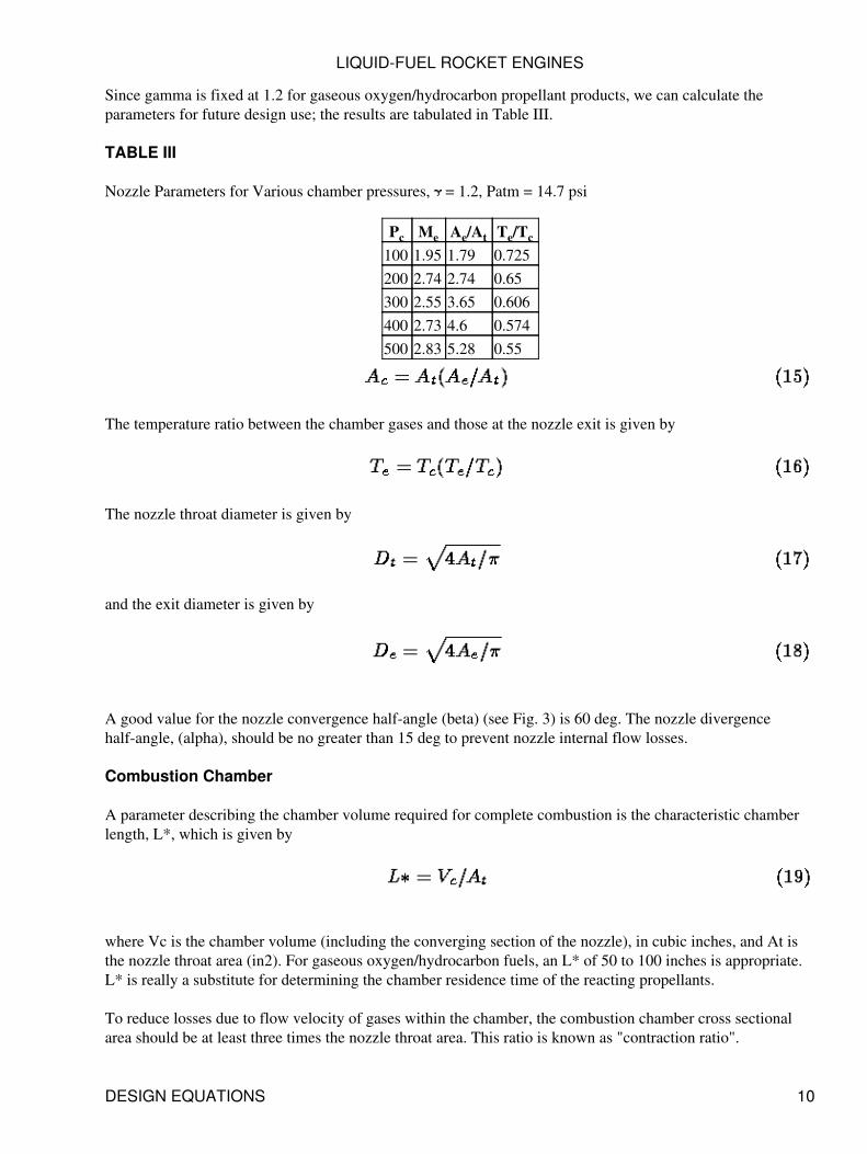
Since gamma is fixed at 1.2 for gaseous oxygen/hydrocarbon propellant products, we can calculate theparameters for future design use; the results are tabulated in Table III.
TABLE III
Nozzle Parameters for Various chamber pressures, = 1.2, Patm = 14.7 psi
Pc Me Ae/At Te/Tc
100 1.95 1.79 0.725200 2.74 2.74 0.65300 2.55 3.65 0.606400 2.73 4.6 0.574500 2.83 5.28 0.55
The temperature ratio between the chamber gases and those at the nozzle exit is given by
The nozzle throat diameter is given by
and the exit diameter is given by
A good value for the nozzle convergence half-angle (beta) (see Fig. 3) is 60 deg. The nozzle divergencehalf-angle, (alpha), should be no greater than 15 deg to prevent nozzle internal flow losses.
Combustion Chamber
A parameter describing the chamber volume required for complete combustion is the characteristic chamberlength, L*, which is given by
where Vc is the chamber volume (including the converging section of the nozzle), in cubic inches, and At isthe nozzle throat area (in2). For gaseous oxygen/hydrocarbon fuels, an L* of 50 to 100 inches is appropriate.L* is really a substitute for determining the chamber residence time of the reacting propellants.
To reduce losses due to flow velocity of gases within the chamber, the combustion chamber cross sectionalarea should be at least three times the nozzle throat area. This ratio is known as "contraction ratio".
LIQUID-FUEL ROCKET ENGINES
DESIGN EQUATIONS 10
The combustion chamber cross-sectional area is given by
The chamber volume is given by
For small combustion chambers the convergent volume is about 1/10 the volume of the cylinrical portion ofthe chamber, so that
The chamber diameter for small combustion chambers (thrust level less than 75 lbs) should be three to fivetimes the nozzle throat diameter so the injector will have usable face area.
Chamber Wall Thickness
The combustion chamber must be able to withstand the internal pressure of the hot combustion gases. Thecombustion chamber must also be physically attached to the cooling jacket and, therefore, the chamber wallthickness must be sufficient for welding or brazing purposes. Since the chamber will be a cylindrical shell, theworking stress in the wall is given by
where P is the pressure in the combustion chamber (neglecting the effect of coolant pressure on the outside ofthe shell), D is the mean diameter of the cylinder, and tw is the thickness of the cylinder wall. A typicalmaterial for small water-cooled combustion chambers is copper, for which the allowable working stress isabout 8000 psi. The thickness of the combustion chamber wall is therefore given by
This is the minimum thickness; actually the thickness should be somewhat greater to allow for welding,buckling, and stress concentration. The thickness of the chamber wall and nozzle are usually equal.
Equation (22) can also he used to calculate the wall thickness of the water cooling jacket. Here again, thevalue of tw will be the minimum thickness since welding factors and design considertions (such as O-rings,grooves, etc.) will usually require walls thicker than those indicated by the stress equation. A new allowablestress value must be used in Equation (22), dependent on the jacket material chosen.
LIQUID-FUEL ROCKET ENGINES
DESIGN EQUATIONS 11
Engine Cooling
The amateur should not consider building uncooled rocket engines since they can operate for only a short timeand their design requires a thorough knowledge of heat and mass transfer engineering. Cooled rocket motorshave provision for cooling some or all metal parts coming into contact with the hot combustion gases. Theinjector is usually self-cooled by the incoming flow of propellants. The combustion chamber and nozzledefinitely require cooling.
A cooling jacket permits the circulation of a coolant, which, in the case of flight engines is usually one of thepropellants. However, for static tests and for amateur operation, water is the only coolant recommended. Thecooling jacket consists of an inner and outer wall. The combustion chamber forms the inner wall and anotherconcentric but larger cylinder provides the outer wall. The space between the walls serves as the coolantpassage. The nozzle throat region usually has the highest heat transfer intensity and is, therefore, the mostdifficult to cool.
The energy release per unit chamber volume of a rocket engine is very large, and can be 250 times that of agood steam boiler or five times that of a gas turbine combustion chamber. The heat transfer rate of a rocketengine is usually 20 to 200 times that of a good boiler. It is apparent, therefore, that the cooling of a rocketengine is a difficult and exacting task. The complete heat transfer design of a rocket engine is extremelycomplex and is usually beyond the capabilities of most amateur builders. Some important empirical designguidelines are available, however, and are listed below:
Use water as the coolant.1. Use copper for the combustion chamber and nozzle walls.2. Water flow velocity in the cooling jacket should be 20-50 ft/sec.3. Water flow rate should be high enough so that boiling does not occur.4. Extend the water cooling jacket beyond the face of the injector.5. A steady flow of cooling water is essential.6.
Heat Transfer
The largest part of the heat transferred from the hot chamber gases to the chamber walls is by convection. Theamount of heat transferred by conduction is small and the amount transferred by radiation is usually less than25%, of the total. The chamber walls have to be kept at a temperature such that the wall material strength isadequate to prevent failure. Material failure is usually caused by either raising the wall temperature on the gasside so as to weaken, melt, or damage the wall material or by raising the wall temperature on the liquidcoolant side so was to vaporize the liquid next to the wall. The consequent failure is caused because of thesharp temperature rise in the wall caused by exessive heat transfer to the boiling coolant.
In water-cooled chambers the transferred heat is absorbed by the water. The water must have in adequate heatcapacity to prevent boiling of the water at any point in the cooling jacket. The total heat tranferred from thechamber to the cooling water is given by
whereQ = total heat transferred, Btu/secq = average heat transfer rate of chamber, Btu/in^2-sec
LIQUID-FUEL ROCKET ENGINES
DESIGN EQUATIONS 12
A = heat transfer area, in2w_w = coolant flow rate, Ib/secc_p = specific heat of coolant, Btu/lb(deg) FT = temperature of coolant leaving jacket, deg FTi = temperature of coolant entering jacket, deg Fthe use of this equation will be illustrated in the section Example Design calculation.
Materials
The combustion chamber and nozzle walls have to withstand relatively high temperature, high gas velocity,chemical erosion, and high stress. The wall material must be capable of high heat transfer rates (which meansgood thermal conductivity) yet, at the same time, have adequate strength to withstand the chambercombustion pressure. Material requirements are critical only in those parts which come into direct contactwith propellant gases. Other motor components can be made of conventional material.
Once the wall material of an operating rocket engine begins to fail, final burn-through and engine destructionare extremely rapid. Even a small pinhole in the chamber wall will almost immediately (within one second)open into a large hole because the hot chamber gases (4000-6000 deg F) will oxidize or melt the adjacentmetal, which is then blown away exposing new metal to the hot gases.
Exotic metals and difficult fabrication techniques are used in today's space and missile rocket engines,providlng a lightweight structure absolutely required for efficient launch and flight vehiclcs. These advancedmetals and fabrication techniques are far outside the reach of the serious amateur builder. However, the use ofmore commonplace (and much less expensive) metals and fabrication techniques is quite possible, except thata flightweight engine will not result. Since almost all amateur rocket firing should be conducted on a statictest stand, this is not a severe restriction to the amateur builder. Experience with a wide variety of rocketengine designs leads to the following rcconmendations for amateur rocket engines:
The combustion chamber and nozzle should be machined in one piece, from copper.1. Those injector parts in contact with the hot chamber gases should also be machined from copper.2. The cooling jacket and those injector parts not in contact with the hot propellant gases, should befabricated from brass or stainless steel.
3.
Expert machine and welding work is essential to produce a safe and useable rocket engine. Shoddy orcareless workmanship, or poor welds, can easily cause engine failure.
4.
Injectors
The function of the injector is to introduce the propellants into the combustion chamber in such a a way thatefficent combustion can occur. There are two types of injectors which the amateur buider can consider forsmall engine design. One of these is the impinging stream injector win which the oxidizer and fuel areinjected through a number of sepaate holes so that the resulting strams intersect with each other. The fuelstream will impinge with the oxidizer stream and both will break up into small droplets. When gaseousoxygen is used as the oxidizer, and a liquid hydrocarbon is used as fuel, the impingement of the liquid streamwith the high velocity gas stream results in diffusion and vaporisation, causing good mixing and efficientcombustion. A disadvantage of this type of injector is that extremely small holes are required for small engineflow rates and the hydraulic characterisitcs and equations normally used to predict injector parameters do notgive good results for small orifices. The small holes are also difficult to drill, especially in soft copper.
However, to provide a complete picture of the equations used in rocket engine design, we present below theequation for the flow of liquid through a simple orifice (a round drilled hole, for example)
LIQUID-FUEL ROCKET ENGINES
DESIGN EQUATIONS 13
wherew = propellalnt flow rate, lb/secA = area of orifice, ft2(deltaP) = pressure drop across orifice, lb/ft^2(rho) = density of propellant, lb/ft^3g = gravitational constant, 32.2 ft/sec2Cd = orifice discharge coefficientThe discharge coefficient for a well-shaped simple orifice will usually have a value between 0.5 and 0.7.
The injection velocity, or vclocity of the liquid stream issuing from the orifice, is given by
Injection pressure drops of 70 to 150 psi, or injection vclocities of 50 to 100 ft/sec are usually used in smallliquid-fuel rocket engines. The injection pressure drop must be high enough to eliminate combustioninstability inside the combustion chamber but must not be so high that the tankage and pressurization systemused to supply fuel to the engine are penalized.
A second type of injector is the spray nozzle in which conical, solid cone, hollow cone, or other type of spraysheet can be obtained. When a liquid hydrocarbon fuel is forced through a spray nozzle (similar to those usedin home oil burners) the resulting fuel droplets are easily mixed with gaseous oxygen and the resultingmixture readily vaporized and burned. Spray nozzles are especially attractive for the amateur builder sinceseveral companies manufacture them commercially for oil burners and other applications. The amateur needonly determine the size and spray characteristics required for his engine design and the correct spray nozzlecan then be purchascd at low cost. Figure 7 illustrates the two types of injectors.
The use of commercial spray nozzles for amateur built rocket engines is highly recommended.
Figure 7 Fuel injectors for Amatuer Rocket Engines.
EXAMPLE DESIGN CALCULATION
Thee following example illustrates the use of the equations, tables and concepts presented in the previoussections.
A small water-cooled liquid-fuel rocket engine is to be designed for a chamber pressure of 300 psi and a thrustof 20 lbs. The engine is to operate at sea level using gaseous oxygen and gasoline propellants.
LIQUID-FUEL ROCKET ENGINES
EXAMPLE DESIGN CALCULATION 14
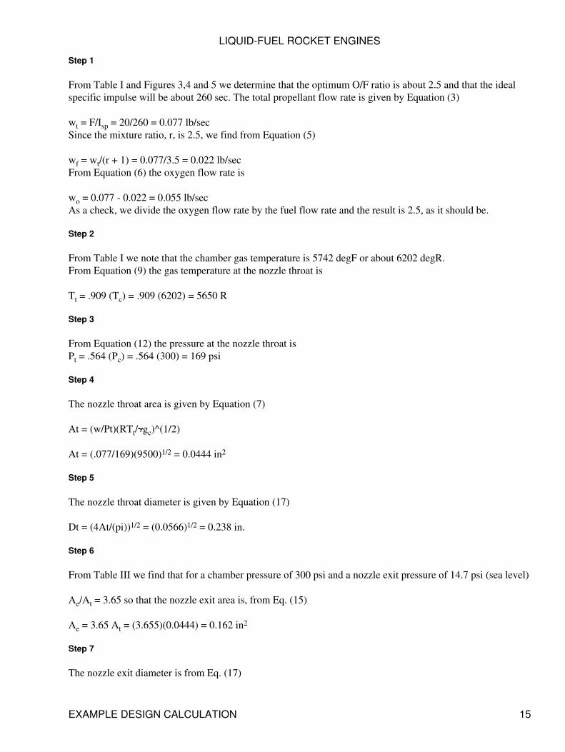
Step 1
From Table I and Figures 3,4 and 5 we determine that the optimum O/F ratio is about 2.5 and that the idealspecific impulse will be about 260 sec. The total propellant flow rate is given by Equation (3)
wt = F/Isp = 20/260 = 0.077 lb/secSince the mixture ratio, r, is 2.5, we find from Equation (5)
wf = wt/(r + 1) = 0.077/3.5 = 0.022 lb/secFrom Equation (6) the oxygen flow rate is
wo = 0.077 - 0.022 = 0.055 lb/secAs a check, we divide the oxygen flow rate by the fuel flow rate and the result is 2.5, as it should be.
Step 2
From Table I we note that the chamber gas temperature is 5742 degF or about 6202 degR.From Equation (9) the gas temperature at the nozzle throat is
Tt = .909 (Tc) = .909 (6202) = 5650 R
Step 3
From Equation (12) the pressure at the nozzle throat isPt = .564 (Pc) = .564 (300) = 169 psi
Step 4
The nozzle throat area is given by Equation (7)
At = (w/Pt)(RTt/ gc)^(1/2)
At = (.077/169)(9500)1/2 = 0.0444 in2
Step 5
The nozzle throat diameter is given by Equation (17)
Dt = (4At/(pi))1/2 = (0.0566)1/2 = 0.238 in.
Step 6
From Table III we find that for a chamber pressure of 300 psi and a nozzle exit pressure of 14.7 psi (sea level)
Ae/At = 3.65 so that the nozzle exit area is, from Eq. (15)
Ae = 3.65 At = (3.655)(0.0444) = 0.162 in2
Step 7
The nozzle exit diameter is from Eq. (17)
LIQUID-FUEL ROCKET ENGINES
EXAMPLE DESIGN CALCULATION 15
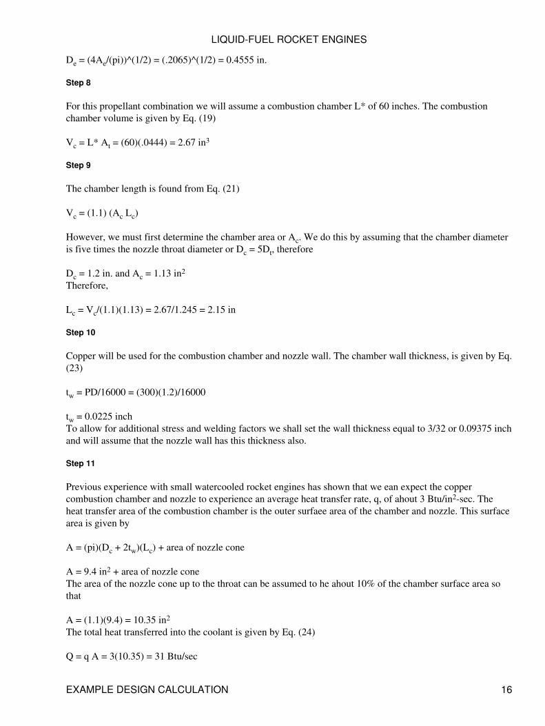
De = (4Ae/(pi))^(1/2) = (.2065)^(1/2) = 0.4555 in.
Step 8
For this propellant combination we will assume a combustion chamber L* of 60 inches. The combustionchamber volume is given by Eq. (19)
Vc = L* At = (60)(.0444) = 2.67 in3
Step 9
The chamber length is found from Eq. (21)
Vc = (1.1) (Ac Lc)
However, we must first determine the chamber area or Ac. We do this by assuming that the chamber diameteris five times the nozzle throat diameter or Dc = 5Dt, therefore
Dc = 1.2 in. and Ac = 1.13 in2
Therefore,
Lc = Vc/(1.1)(1.13) = 2.67/1.245 = 2.15 in
Step 10
Copper will be used for the combustion chamber and nozzle wall. The chamber wall thickness, is given by Eq.(23)
tw = PD/16000 = (300)(1.2)/16000
tw = 0.0225 inchTo allow for additional stress and welding factors we shall set the wall thickness equal to 3/32 or 0.09375 inchand will assume that the nozzle wall has this thickness also.
Step 11
Previous experience with small watercooled rocket engines has shown that we ean expect the coppercombustion chamber and nozzle to experience an average heat transfer rate, q, of ahout 3 Btu/in2-sec. Theheat transfer area of the combustion chamber is the outer surfaee area of the chamber and nozzle. This surfacearea is given by
A = (pi)(Dc + 2tw)(Lc) + area of nozzle cone
A = 9.4 in2 + area of nozzle coneThe area of the nozzle cone up to the throat can be assumed to he ahout 10% of the chamber surface area sothat
A = (1.1)(9.4) = 10.35 in2
The total heat transferred into the coolant is given by Eq. (24)
Q = q A = 3(10.35) = 31 Btu/sec
LIQUID-FUEL ROCKET ENGINES
EXAMPLE DESIGN CALCULATION 16
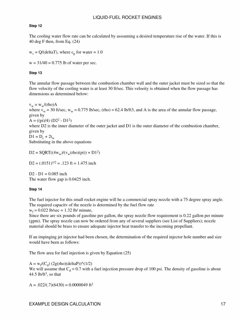
Step 12
The cooling water flow rate can be calculated by asssuming a desired temperature rise of the water. If this is40 deg F then, from Eq. (24)
wv = Q/(deltaT), where cp for water = 1.0
w = 31/40 = 0.775 lb of water per sec.
Step 13
The annular flow passage between the combustion chamber wall and the outer jacket must be sized so that theflow velocity of the cooling water is at least 30 ft/sec. This veloeity is obtained when the flow passage hasdimensions as determined below:
vw = ww/(rho)Awhere vw = 30 ft/sec, ww = 0.775 lb/sec, (rho) = 62.4 lb/ft3, and A is the area of the annular flow passage,given byA = ((pi)/4) (D22 - D12)where D2 is the inner diameter of the outer jacket and D1 is the outer diameter of the combustion chamber,given byD1 = Dc + 2twSubstituting in the above equations
D2 = SQRT((4ww)/(vw(rho)(pi)) + D12)
D2 = (.0151)1/2 = .123 ft = 1.475 inch
D2 - D1 = 0.085 inchThe water flow gap is 0.0425 inch.
Step 14
The fuel injector for this small rocket engine will he a commercial spray nozzle with a 75 degree spray angle.The required capacitv of the nozzle is determined by the fuel flow ratewf = 0.022 lb/sec = 1.32 lb/ minute,Since there are six pounds of gasoline per gallon, the spray nozzle flow requirement is 0.22 gallon per minute(gpm). The spray nozzle can now be ordered from any of several suppliers (see List of Suppliers); nozzlematerial should be brass to ensure adequate injector heat transfer to the incoming propellant.
If an impinging jet injector had been chosen, the determination of the required injector hole number and sizewould have been as follows:
The flow area for fuel injection is given by Equation (25)
A = wf/(Cd) (2g(rho)(deltaP))^(1/2)We will assume that Cd = 0.7 with a fuel injcction pressure drop of 100 psi. The density of gasoline is about44.5 lb/ft3, so that
A = .022/(.7)(6430) = 0.0000049 ft2
LIQUID-FUEL ROCKET ENGINES
EXAMPLE DESIGN CALCULATION 17
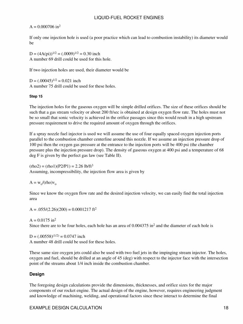
A = 0.000706 in2
If only one injection hole is used (a poor practice which can lead to combustion instability) its diameter wouldbe
D = (4A(pi))1/2 = (.0009)1/2 = 0.30 inchA number 69 drill could be used for this hole.
If two injection holes are used, their diameter would be
D = (.00045)1/2 = 0.021 inchA number 75 drill could be used for these holes.
Step 15
The injection holes for the gaseous oxygen will be simple drilled orifices. The size of these orifices should besuch that a gas stream velocity or about 200 ft/sec is obtained at design oxygen flow rate. The holes must notbe so small that sonic velocity is achieved in the orifice passages since this would result in a high upstreampressure requirement to drive the required amount of oxygen through the orifices.
If a spray nozzle fuel injector is used we will assume the use of four equally spaced oxygen injection portsparallel to the combustion chamber centerline around this nozzle. If we assume an injection pressure drop of100 psi then the oxygen gas pressure at the entrance to the injection ports will be 400 psi (the chamberpressure plus the injection pressure drop). The density of gaseous oxygen at 400 psi and a temperature of 68deg F is given by the perfect gas law (see Table II).
(rho2) = (rho1)(P2/P1) = 2.26 lb/ft3Assuming, incompressibility, the injection flow area is given by
A = wo/(rho)vo
Since we know the oxygen flow rate and the desired injection velocity, we can easily find the total injectionarea
A = .055/(2.26)(200) = 0.0001217 ft2
A = 0.0175 in2
Since there are to he four holes, each hole has an area of 0.004375 in2 and the diameter of each hole is
D = (.00558)(1/2) = 0.0747 inchA number 48 drill could be used for these holes.
These same size oxygen jets could also be used with two fuel jets in the impinging stream injector. The holes,oxygen and fuel, should be drilled at an angle of 45 (deg) with respect to the injector face with the intersectionpoint of the streams about 1/4 inch inside the combustion chamber.
Design
The foregoing design calculations provide the dimensions, thicknesses, and orifice sizes for the majorcomponents of our rocket engine. The actual design of the engine, however, requires engineering judgmentand knowledge of machining, welding, and operational factors since these interact to determine the final
LIQUID-FUEL ROCKET ENGINES
EXAMPLE DESIGN CALCULATION 18
configuration of the engine and its components. Perhaps the best way to accomplish the final design is to sitdown with appropriate drafting materials and begin to draft a cross-section view of the engine. A scale of 2/1(or twice actual size) is about right for these small engines and will enable the designer to better visualize theentire assembly.
Using the dimensions obtained in the example calculation, and the design technique described shove, therocket engine assembly design shown in Figure 8 is obtained. The engine design features easy fabrication andassembly.
FABRICATION
The fabrication and assembly of a small liquid fuel rocket engine is no more difficult than the more seriousamateur machine projects, such as model steam engines, gasoline engines, and turbines. Because the rocketengine has no rotating parts, dynamic balance of components is not required. However, the use of quality,homogeneous materials and careful fabrication technique are definitely required to produce a safe, workingrocket engine.
A properly desgined small liquid-fuel rocket engine requires the following machine and hand tools:
6" or 10" metal-turning lathe, with attachments1. Precision drill press2. hand files, calipers, micrometers, etc.3. oxy-acetylene torch or small arc welder.4.
Since a properly designed engine will have symmetrical parts, a milling machine or planer will not berequired. The metal-turning lathe should have a repeatable accuracy of 0.001 inch. The drill press will he usedto drill small diameter holes and should have a true running, high speed chuck.
Mensuration equipment such as calipers, micrometers, etc., must be capable of inside and outside diametermeasurements, lengths, and should be used to locate holes, recesses, and other features prior to actualmachining.
The joining of the various engine components is especially critical since the engine will operate at highpressure and high temperature.
LIQUID-FUEL ROCKET ENGINES
FABRICATION 19
Figure 8 Assembly drawing of small liquid-fuel rocket engine. (1) injector assembly, (2) O-ring, (3) liquidfuel, (4) gaseous oxygen (5) engine mount, (6) coolant, (7) fuel spray nozzle, (8) combustion chamber, (9)
outer shell, (10) coolant.
The ability of the welder, and the welding techniques employed, should be as good as those required foraircraft work. Metal joints must be clean, vith a close fit between parts to ensure adequate weld strength andintegrity. To the extent possible assembled conponents should be tested with water (or nitrogen gas, but that isdangerous) prior to actual use with propellants. Repair of leaks or initially poor welds must be carefully donewith subsequent re-testing with pressurized water (called hyrdo-testing or hydrostatic testing).
As discussed previously, the combustion chamber should built as a one-piece unit. This arrangement, whilemore difficult from a machining point of view, eliminates the requirement for a joint of some knd between thetwo parts; this joint would be exposed to the hot combustion gases (5700 degF) on one side and would, in allprobability, fail. Building the combustion chamber and nozzle in one piece eliminates this potential failurepoint. Care must be exercised during the machining of the copper chamber/nozzle to ensure constant wallthickness and the correct taper in the nozzle region. Thin wall sections are potential failure points and couldresult in almost immediate catastrophic failure during firing.
Machining of the outer shell or jacket is less critical than the combustion chamber/nozzle. Typical materialsfor this part are stainless steel or brass. The inside diameter of the shell should have a smooth finish to reducecooling pressure drop, nnd the outside finish of the shell, which will be visible to the world, should reflect thecare and concern of the machinist. The shell will also contain the coolant entry and exit ports. Since thecoolant (typically water) will probably have an entry pressure of 60 to 100 psi, these ports and fittings shouldbe constructed with some care. The use of flare type fittings with metal tapered seats (such as thosemanufactured by Parker or Weatherland) is highly reccomended. The shell will also feature a method ofattaching the injector and for mounting the engine to a test or thrust stand. As shown in Figure 8, these twomounting requirements can be easily combined to simplify the design. The forces to be considered when
LIQUID-FUEL ROCKET ENGINES
FABRICATION 20
designing the shell are not the thrust forces (which are small, typically on the order of 20-30 lbs) but, ratherthe pressure forces attempting to separate the injector from the shell. The pressure acting on the injector areaout to the point of sealing between the injector and the outer shell is the combistion chamber pressure, whichis typically 100 to 300 psi. The force attempting to separate the injector from the shell is slightly over 600 lbsfor the design shown in Figure 8 at a combustion pressure of 300 psi. The bolts holding the two componentstogether (and in this case also holding the assembly to the test mount) must withstand this force with andadequate safety factor (typically a factor of two). THe number and size of bolts required can be obtained fromTable IV, which gives the average load capacity of high strength steel bolts of various sizes. The strength ofthese bolts, however, depends to some extent on the adequacy of the threads in tapped holes, the tappedmaterial, and the bolt tightening procedure used in assembly.
TABLE IV
Average Load CapaciLy of high Strength Steel Bolts, SF = 2
Bolt Size | Load Capacity, lb
10-32 15001/4-20 24001/4-28 27503/8-16 5800
The outer shell must also contain a sealing device to prevent the high pressure combustion chamber gas fromflowing back past the injector. With an appropriately configured water-cooled design, the use of anelastomeric O-ring is highly desirable. A standard neoprene O-ring (manufactured by a number of companies,see List of Suppliers) will give reliable service if the surrounding metal does not exceed a temperature of200-300 degF . Dimenstions and design parameters for O-rings and O-ring grooves are given in maufacturerssupply catalogs.
Another method of sealing is the use of an asbestos-copper crush gasket (very similar to those used onautomobile sparkplugs, only larger; see List of Suppliers). The copper crush gasket is positioned by aV-groove cut in the surface of the outer jacket at the sealing point. The mating surface of the injector shouldbe smooth and flat with no machine marks.
Figure 9 illustrates the relationship between an O-ring and a copper crush gasket and their mating surfaces.
Figure 9 Detail on O-ring and crush gasket sealing methods. O-ring groove dimensions are critical and shouldbe obtained from suppliers handbooks. Crush gasket groove dimensions are non-critical; groove depth should
be about 1/3 the thickness of uncrushed gasket.
The injector should be fabricated from copper to provide maximum heat transfer from the injector face to theincoming propellants. The outer shell of the injector can be made from either copper, stainless steel, or brass.However, since the propellant inlet fittings (again these should be the tapered seat, metal-to-metal kind)should he stainless steel for best results. It is usually a good idea to make the injector outer shell from stainlesssteel so that the inlet fittings can be arc welded. Then the outer shell can be attached to the remainder of theinjector by silver brazing without weakening the inlet fitting welds.
LIQUID-FUEL ROCKET ENGINES
FABRICATION 21
Injection holes for the gaseous oxygen (and for the fuel, if impinging jets are used) will usually be made withnumbered drills of small diameter. Extreme care should be used in drilling these holes, especially in softcopper. The drilled hole should have an entry and exit free from burrs or chips. It is vitally important thatinjector components be thoroughly cleaned and deburred prior to assembly. After injector welding, hot watershould be used to thoroughly clean the injector assembly of brazing flux and residues, and the assemblyshould receive a final rinse in acetone or alcohol.
TESTING EQUIPMENT
In this section we shall discuss the auxilliary equipment needed to operate the rocket engine, the installation ofthis equipment, and its safe use in engine operation.
Feed System
The feed system for amateur rocket engine testing consists of a tank to store the liquid fuel, a regulated supplyof high pressure nitrogen gas to force the fuel from the tank into the engine, a regulated supply of highpressure gaseous oxygen, and a control device for regulating the propellant flow rates. A typical pressurizingfeed system is shown schematically in Figure 10.
Feed System Components
The components of a rocket engine feed system are precision instruments designed to handle gas and/orliquids at high pressure. While many of the components suitable for use in amateur rocket feed systems arereadily available from welding or automohile parts suppliers, they are usually relatively expensive. Theamateur builder should expect the assembly of the feed system to be an expensive project which, however,need be done only once. The use of quality products, made to do the job or very carefully modified andpre-tested, is mandatory for safe operation of amateur rocket engines.
High Pressure Gas Cylinders
Gases stored in cylinders at high pressure (usually about 1800 psi) are readily obtained from any bottled gassupplier or from many welding suppliers. Special fittings with nonstandard threads are used to prevent use ofincorrect equipment with the cylinders. Although cylinders can be purchased, they are usually rented and thenreturned to the supplier for recharge at a nominal fee. High pressure gas cylinders should never he dropped ormishandled. Cylinders should be stored so they cannot fall over or inadvertently roll; the best way of securingis to chain or strap the cylinders to an appropriate stand or worktable. When cylinders are not in use the capshould be kept on to protect the cylinder valve. Several suppliers of high pressure gases publish instructionbooks on the care and use of high pressure cylinders (see Bibliography); the amateur is encouraged to readand follow these professional instructions.
LIQUID-FUEL ROCKET ENGINES
TESTING EQUIPMENT 22
Figure 10 Schematic diagram of gas pressure feed system. Propellants are a liquid fuel and gaseous oxygen.(1) high pressure gaseous nitrogen supply, (2) pressure regulator, (3) check valve, (4) fuel tank, (5) gaseous
oxygen cylinders, (6) relief valve, (7) vent valve, (8) fill port, (9) drain valve, (10) remotely operatedpropellant control valve, (11) fuel filter, (12) purge valve, (13) rocket engine. P is pressure gauge.
Gaseous Nitrogen
Nitrogen is an inert gas compatible with all normally available materials. The amateur builder will have littledificulty with materials of construction for nitrogen but must be careful that all components are suitable forhigh pressure service. Cleanliness of components is important for proper and reliable operation,
Gaseous Oxygen
Oxygen will not itself burn but does vigorously support the rapid combustion of almost all other materials.The amateur must be concerned not only with suitablility of components for high pressure service but alsomust use only components that are made from oxygen compatible materials and that are cleaned for oxygenservice. All items, including lines, fittings, valves, regulators, etc., MUST be absolutely free from oil, grease,and similar contaminants. Thorough cleaning of all items in solvent, followed by a complete rinse in acetone,is an absolute must. Orders for commercial items should he marked to indicate their intended use with highpressure gaseous oxygen. Many commercial suppliers of valves and regulators offer a special service forcleaning their products for oxygen service. The amateur should avail himself of these services wheneverpossible, even though they will add slightly to the initial cost of the component.
When cleaning components with solvent or acetone, the amateur builder should observe all rules of safetyapplying to these chemicals. They are toxic and easily ignited. Cleaning should be done outside and awayfrom huildings, fires, or other possible ignition sources. These fluids should not be stored indoors but invented lockers away from main buildings.
LIQUID-FUEL ROCKET ENGINES
TESTING EQUIPMENT 23
Fuel Tank
The fuel tank is a closed vessel which contains the liquid fuel at moderate pressure (300-500 psi). Tanks ofvarious sizes and shapes, made from carbon- or stainless steel, are offered to the public from war surplusoutlets. The amateur builder should be very careful if he decides to use such a tank. They should not bemodified since in nearly all cases they are thin wall pressure vessels made for aircraft service, and additionaloutlets or welding to the tank wall could seriously weaken the tank. In all cases the tank should behydrostatically tested to at least 1 1/2 times desired operating presure before use in the rocket engine feedsystem.
The amateur may build (or have built) a tank especially for his requirements. Seamless tubing or pipe (mildsteel or stainless steel) with welded flat end plates makes an excellent tank. Outlet ports are easily tapped inthe flat end plates, The tank wall thickness is given by Equation (22)
t_w = PD/2Swhere P is the pressure in the tank (1 1/2 times the desired operating pressure), D is the outside diameter ofthe tank, t_w is the wall thickness, and S is the allowable stress. The size of the tank is determined by the sizeof the rocket engine and the desired operating time. The engine discussed in Example Design Calculation hada fuel flow rate of 0.022 lb/sec. A tank with a 4-inch inside diameter and 12 inches long would hold enoughgasoline to run this engine for 175 seconds. If the tank outside diameter is 4.5 inches, the allowable stress inthe steel is 20,000 psi, and the operating pressure is 500 psi so that the design pressure is 750 psi, a tankminimum wall thickness of 0.085 inch is calculated. A wall thickness of 0.250 inch is chosen to allow forwelding factors, stress concentrations, and the size of available seamless tubing. The tank inside diameter is4.0 inches. The flat end plates for this tank should be at least twice the thickness of the tank wall (i.e. for thiscase, at least 1/2 inch thick). Drilling and tapping should be done prior to welding, to prevent oil and metalchips from falling into the tank. Welding should be done by an expert with several passes for each end plate(see Figure 11). End plate ports should then be re-tapped. The tank should be thoroughly cleaned andhydrostatically tested prior to use in the rocket engine feed system.
The fuel tank should contain enough ports, or the tank plumbing should be so arranged, that a safety reliefvalve (either spring loaded or a burst disc), gas inlet port, load and vent port, and fuel outlet and drain areavailable. Many of these functions can be incorporated as part of the gas inlet and fuel outlet plumbing so thatonly two ports, one on each end of the tank are required.
Figure 11 Fuel tank end detail. Several weld passes should be used to attach the end plates to the seamlesstubing.
Tanks made from seamless tubing should not be greater than six inches in diameter; wall stress is a functionof diameter, and at high stress, specialized design information, not usually available to the amateur builder, isrequired. Also, the force on the tank end plates increases rapidly with tank diameter.
LIQUID-FUEL ROCKET ENGINES
TESTING EQUIPMENT 24
Gaseous Nitrogen Regulator
The purpose of a regulator is to maintain a constant pressure on the downstream side of the regulator as thepressure in the gas cylinder on the upstream side decreases. A good quality regulator will maintain thedownstream pressure quite accurately over a range of gas flow rates as long as the upstream cylinder pressuredoes not decrease so as to become too close to the downstream pressure. Thus, all the gas in the cylinder is notusable since some excess pressure (hence, gas) is required to drive the gas through, and maintain control of,the regulator. The flow rate of nitrogen gas required for the fuel from the tank is relatively small and could behandled by a regular gaseous oxygen welding regulator equipped with nitrogen cylinder fittings. However,most welding regulators do not permit adjustment to the high downstream pressure required for rocket engineoperation. A number of commercial firms (see List of Suppliers) market regulators for non-welding purposesthat are admirably suited for fuel tank pressurization. Especially attractive is the Grove Mity-Mite regulatorwith internal regulation. Inexpensive, special fittings are required to attach these regulators to the gas cylinder.These fittings are available from several sources (see List of Suppliers).
Gaseous Oxygen Regulator
The discussion of regulators for gaseous nitrogen service applies to gaseous oxygen also, except that theregulator should be especially cleaned for oxygen service and, if possible, metal-to-metal seats should be usedwithin the regulator. Regulator manufacturers should be consulted for reccomendations on seat materials foruse with gaseous oxygen in their regulators. Special fittings for attaching the regulator to the oxygen cylinderare available from the sources supplying nitrogen cylinder fittings. These sources can also supply cylindermanifold kits so that two or more oxygen cylinders can be used simultaneously to achieve long engine rundurations.
Propellant Control Valves
The propellant control valves allow the operator to start and then manually remote-control the flow of eachpropellant in to the rocket engine. These valves should be stainless steel needle valves with Teflon packing orseals. Many manufacturers make this kind of valve (see List of Suppliers). The valve for gaseous oxygenshoud be larger than the valve for the fuel line. Engines of the size discussed in Example Design Calculationshould use a 1/4-inch ftel valve (that is, 1/4 National Pipe Thread line size) and a 1/2-inch oxygen valve. Thetubing actnally entering, and leaving, the valves need not be this large, but the valves themselves should be asindicated to afford a range of flow control with minimum pressure drop across the valve. Since these valvescontrol the flow of propellants, they should be mounted near the tanks and engine on the test stand, andoperated remotely by means of valve stem extensions (see discussion on Test Stand).
Other Valves
Other valves required in the feed system include the fuel tank vent and fill valve, the drain valve, and thenitrogen purge valve. Inexpensive, high quality ball valves are highly reccomended for these functions sincethey offer positive shut-off, easy operation with handle indication of on or off, and full line opening. Brass orstainless steel valve bodies with Teflon seats are acceptable, and the valves may be line or panel mounted (seeList of Suppliers).
Check Valves
Check valves permit fluid flow in one direction only. They are widely used in the aircraft and hydraulicindustry and are manufactured by many companies. l/4-inch line size is recommended for all functions shownin Figure 10 with the exception Of the gaseous oxygen line check valve which should feature metal-to-metalseats and be at least 3/8inch line size. Check valves should be thoroughly cleaned prior to use and tested toinsure that tlle check is working properly.
LIQUID-FUEL ROCKET ENGINES
TESTING EQUIPMENT 25
Relief Valves
The fuel tank requires a relief device of some type to prevent tank failure in the event of over-pressurization.While this is high unlikely, it could happen if the gaseous nitrogen regulator failed to function or shut-offproperly. An adjustable spring-loaded relief valve is reccomended because it may be set to different pressuresas feed system uses change, and because, if used, does not have to be replaced. An alternate device is the burstdisc which ruptures at a preset pressure and relieves the overpressure in the tank. Burst discs requirereplacement after actuation and are not pressure adjustable. A different disc must be used for each pressurerange desired.
Fuel Filter
Fuel injection holes on small liquid-fuel rocket engines are easily plugged with contaminants from tbe fueltank and control system. A fuel filter which can filter out particles down to ten microns in size is highlyreccommended and will save tbe amateur builder much grief when actual testing is started. Several concernsmake small filters suitable for rocket engine feed systems (see List of Suppliers).
Pressure Gauges
Fuel, oxygen, water, and combustion chamber pressure are essential measurements for rocket engineoperation. Buordon-tube pressure gauges offer accuracy, ruggedness, low cost, and availability for thisrequirement. Numerous manufacturers make these gauges in a bewildering variety of styles, sizes, and prices.Bronze Bourdon tubes are recommended since they are fully compatible (when cleaned) with gaseous oxygenor hydrocarbon fuel and are so widely used that significant cost savings are possible.
Small (2 1/2 or 3-inch diameter) high pressure gauges similar to those used on oxygen welding regulatorsshould be used by the amateur builder for measuring pressure in the high pressure gas cylinders or manifolds.These gauges can be obtained from a welding supply shop.
Gauges for fuel, oxygen, water, and combustion chamber pressure should be at least 3 1/2 inch diameter foreasv reading, from a distance. These 3 1/2 Acaloy gauges of Helicoid (see List of Suppliers) arerecommended because of their reliability and low cost. These gauges are easily panel mounted and make aneat test stand installation.
Plumbing
Plumbing refers to tbe flow tubes and fittings used to collnect the components discussed previously. 1/4-inchdiameter stainless steel tubing for the fuel and nitrogen systems and 3/8 inch diameter stainless tubing for theoxygen line are recommended. Flare fittings with metal to metal seats are also recommended for joining thetubing to other components. 1/4 and 3/8 inch diameter copper tubing can also be used for the fuel, oxygen,and nitrogen supply system but is not as desirable as stainless steel and is more easily flared. The amateurbuilder should use only good flaring tools and should form or bend tubing only with a tube bender. Where thefittings screw into fuel tank, valve, or other components having pipe threads, the use of Teflon tape on thethreads is recommended. No other pipe thread compound should be used, especially on gaseous oxygencomponents.
TEST STAND
The amateur rocket engine test stand is a structure which incorporates a method for firmly mounting therocket engine (preferably in a nozzle-down attitude), a mounting for the propellant flow control needle valves,the fuel tank and associated plumbing, and the oxygen and nitrogen cylinders with regulators and associated
LIQUID-FUEL ROCKET ENGINES
TESTING EQUIPMENT 26
plumbing. The operator's station, which is really a part of the test stand, should be physically separated fromthe test stand proper by at least 20 feet, witll a shrapnel barricade between. The operator's station shouldcontain the control valve extensions, the ignition system battery and associated switches, and a mirror systemso that the operator does not directly view the operating rocket engine.
The greatest hazard in testing small rocket engines is from shrapnel in the event of engine explosion ordisintigration. Therefore, the test stand proper should be suitably barricaded to reduce shrapnel effect in alldirections.
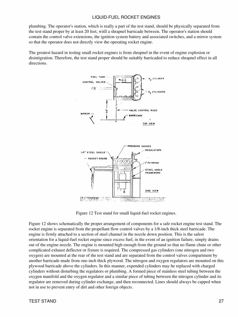
Figure 12 Test stand for small liquid-fuel rocket engines.
Figure 12 shows schematically the proper arrangement of components for a safe rocket engine test stand. Therocket engine is separated from the propellant flow control valves by a 1/8-inch thick steel barricade. Theengine is firmly attached to a section of steel channel in the nozzle down position. This is the safestorientation for a liquid-fuel rocket engine since excess fuel, in the event of an ignition failure, simply drainsout of the engine nozzle. The engine is mounted high enough from the ground so that no flame chute or othercomplicated exhaust deflector or fixture is required. The compressed gas cylinders (one nitrogen and twooxygen) are mounted at the rear of the test stand and are separated from the control valves compartment byanother barricade made from one-inch thick plywood. The nitrogen and oxygen regulators are mounted on thisplywood barricade above the cylinders. In this manner, expended cylinders may he replaced with chargedcylinders without disturbing the regulators or plumbing. A formed piece of stainless steel tubing between theoxygen manifold and the oxygen regulator and a similar piece of tubing between the nitrogen cylinder and itsregulator are removed during cylinder exchange, and then reconnected. Lines should always be capped whennot in use to prevent entry of dirt and other foreign objects.
LIQUID-FUEL ROCKET ENGINES
TEST STAND 27
The fuel tank is mounted beteeen the forward steel barricade and the rear plywood barricade on a metalcross-piece attached to both barricades. The tank is mounted in the vertical position with the liquid outlet atthe bottom.
The propellant flow control valves are mounted one atop the other in a metal bracket which is attached to theforward steel barricade. Panel mounted needle valves are recommended since they facilitate mounting in themanner described, and do not place mounting or operating stresses on the propellant flow tubing. Valve stemextensions, made from 1/4-inch pipe permit operation of the control valves from the operator's remote controlstation, which is located at least twenty feet from the test stand proper. Pressure gauges for fuel tank pressure,oxygen line pressure, cooling water exit pressure and combustion chamber pressure are mounted in a panelwhich is attached to the forward and rear barricades and which faces the operator's remote station.
Cooling water for the rocket engine is brought into a hose coupling attached to the stand, with semi-permanentplumbing between the coupling and the rocket engine. Water flowing from the cooling jacket should bedirected away from the engine or can be directed downward onto a 3-inch deep layer of coarse stones laidbeneath the roeket engine exhaust. These stones will prevent the engine exhaust from picking up dirt and dust;the water will cool the stones and extend their useful life. The jet of cooling water can be observed by theoperator as an indication that cooling water is actually flowing through the engine.
The test stand proper should have a framework made from welded or bolted steel angle. The forward steel andrear plywood barricade are bolted to this angle framework providing rigidity and strength. Thee test standshould be firmly attached to the surface Of the test area either by bolting to a concrete pad or by weighingdown with sand bags or concrete weights.
SAFETY
Because of the physical hazards involved in handling propellants and controlling high pressure combustionproeesses, certain elementary safety precautions must be observed in static testing of rocket engines. Duringthe design, and later, the operation of amateur liquid rocket engines, the following general safety precautionsshou1d be observed:
The operator should be protected by a suitable barricade located some distance (at least 20 feet) fromthe test unit.
1.
Control of valves during engine ignition and steady-state operation should be by remote means, whichfor amateur units is best achieved by manual control of needle valves via valve stem extensions.
2.
A large chemical fire extinguisher (or, at least, a plentiful supply of water) should always be on hand.3. The operator shOuld not view the test unit directly, but should use a mirror arrangement (somewhatlike a periscope) or use a thick layer of reinforced safety glass attached to the operator's barricade.REMEMBER, the primary danger is from shrapnel in the event of engine explosion.
4.
Separating of fuel and oxidizer storage reduces the fire and explosion hazard and limits the amount ofpropellant stowed in any one area.
5.
The test stand unit should be barricaded on several sides to reduce shrapnel effect in event ofexplosion.
6.
Valves, pressure pauges, and other components which directly sense fluid properties should not belocated in the operator's station, but should be on the test stand and remotely read. This rule does notapply to electrical instrumentation wherein a transducer is located on the test stand and an electricalreadout (such as a meter) is located at the operator's station (this type of instrumentation is veryexpensive and is beyond the reach of most amateurs).
7.
Warning signals should be given prior to tests (or whenever gas cylinder valves are open) to notifypersonnel that the area is hazardous. A test must NEVER be conducted until the operator has assured
8.
LIQUID-FUEL ROCKET ENGINES
SAFETY 28
himself that all personnel are behind safety barricades or otherwise protected.Personnel should be permitted to work in the test area only if fuel and oxidizer are separated and notpressurized.
9.
Personnel handling propellants should wear safety equipment such as gloves, face shields, or rubberaprons. Remember that most fuels are toxic; do not breathe fuel vapors for even a short time.
10.
No smoking is ever permitted anywhere near a test area when propellants are alse present, Remembervapors from hydrocarbon fuels (such as gasoline) can travel long distances from the test area and canbe ignited at a remote point travelling back to the test stand.
11.
A check-off list is helpful when conducting a rocket engine firing and should be made up of bothtechnical events and safety items to be completed prior to the firing.
12.
ENGINE CHECK-OUT and CALIBRATION
After the rocket engine has been fabricated, several check-out tests and flow calibrations should be made priorto testing with live propellants.
Leak Testing
Connect the engine cooling jacket to a readily available source of pressurized water (such as lawn or housesupply; pressure should be 50-100 psi with no flow). Attach a pressure gauge to the outlet port of the jacketand open the water valve, allowing water to fill the jacket. Observe the jacket and engine for leaks. Thereshould be no leaks.
A similar pressure check should be performed on the fuel manifold of the injector. Since the injector face isnot easily blanked off, perform this test by flowing water through the injector. Use a filter in the vater line toavoid plugging the small fuel injection holes. Use a pressure gauge attached to the water line as near to theinjector fuel entry port as possible. There should be no leaks.
Flow Calibration
The water flow rate through the engine cooling jacket should be determined for various inlet pressures. Use abathroom or other available scale to weigh, in a container, water flowing through the engine over a timedperiod. Water pressure can be measured either at the entrance or exit of the cooling jacket. Attach a flexiblehose (garden variety will do) to the outlet of the cooling jacket and start water flowing through the jacket atthe desired pressure. Once steady flow has been achieved quickly move the hose outlet into the catchcontainer for a period of 30 seconds, then quickly remove the hose from the container. Use a stop or sweepsecond watch for the timing and be accurate! Obtain the net weight of collected water by subtracting from theweight of the filled container its empty weight. Divide the net weight by the time during which water wascollected and the result will be water flow rate in lb/sec. This operation should be repeated several times atdifferent pressures to obtain the flow characteristics of the coolant jacket. If insufficient water pressure isavailable to achieve the design water flow rate, check the size of tubing or hose used between the water sourceand the engine; it may be restricting the water flow rate. Check also the size of the flexible duct hose used. Ifthese tests show that greater pressure is required to achieve the desired flow rate, a different source of coolingwater may be required. Under extreme conditions, an air-presurized water tank or a motor-driven pump maybe required. Another solution is to disassemble the engine and re-bore the outer shell to open up the waterflow passage. Material should NOT be removed from the combustion chamber/nozzle.
Flow rate tests of the injector, using water, can be performed in a manner similar to the cooling systemcalibration, although their worth is questionable. The flow characteristics of water and the hydrocarbon fuelsare different, so that a water calibration is not directly comparable to what will occur when fuel is used.
LIQUID-FUEL ROCKET ENGINES
ENGINE CHECK-OUT and CALIBRATION 29
However, the pressure drop required to flow a given quantity of water will provide some indication of howclosely design objectives were achieved. This test should be conducted in the same manner as the coolingwater calibration test except that the flow time should he long enough to accumulate at least ten pounds ofwater.
Test Stand Checkout
After the test stand and operator's area are completed and components installed, tests should the conducted todetermine that no gas or liquid leaks will occur when actual propellants are used. Fill the tank with cleanwater. Cap off the fuel and oxygen lines where they would normally attach to the engine. Pressurize thesystem to 100 psi and check for leaks. A soap solution can be used to check around all fittings and seals. Soapbubbles indicate the presence of a gas leak. If no leaks are present, increase the pressure to 200 psi and repeatthe detection procedure. Continue this procedure until the test stand operating pressure is reached and no leaksare present. Depressurize the system and refill the fuel tank with clean water. Attach the rocket engine to itstest mount and connect all tubing. Pressurize the stand in the normal manner and practice the ignition andoperating sequence using water as fuel (gaseous oxygen can safely he used in these tests, if desired). If noleaks develop, empty the fuel tank of water and dry by flushing with nitrogen gas for several seconds. Theengine and test stand are now ready for their first hot firing.
IGNITION and OPERATION
Discussion of propellant ignition has been reserved until this point since it is really a test stand function and isrequired only for actual operation of the engine. The propellants used in amateur rocket engines require aseparate source for ignition. Because the engines are small, the use of an engine-mounted spark plug is notgenerally feasible. Even if it were, the ignition of incoming propellants in the combustion chamber by a smallspark plug is dangerous and unreliable. Propellant timing is extremely important in a bi-propellant liquidrocket engine. An excess of either propellant (if both are liquid) in the combustion chamber can lead to severeover-pressure upon ignition (known as "hard" start) and possible fracture of the combustion chamber. Theamateur engine using gaseous oxygen is not nearly as sensitive to hard starts as if the oxidizer were a liquid.
Hundreds of tests with small liquid-fuel rocket engines employing gaseous oxygen as the oxidizer haveindicated that hot-source ignition provides excellent propellant ignition characteristics, and drastically reduceshard starts. Hot-source ignition works as follows: two lengths of insulated #16 or #18 solid wire are tapedtogether and their exposed ends are bent to form a spark gap of about 3/32-inch. A small amount of cotton iswrapped around, or attached to, thc wires very near the spark gap but not obstructing it. This ignitionassembly is pushed through the nozzle into the combustion chamber of the rocket engine so that the spark gapis in the lower end of the combustion chamber but not blocking the nozzle throat. The wires outside the engineare bent or taped to hold the ignition assembly in position during the ignition phase. The free ends of the twowires are attached to the spark source (a Ford Model-T spark coil is ideal for this purpose). Figure 13 detailsthis hot-source igniter. The ignition procedure, after the test stand is prepared for firing is:
LIQUID-FUEL ROCKET ENGINES
ENGINE CHECK-OUT and CALIBRATION 30
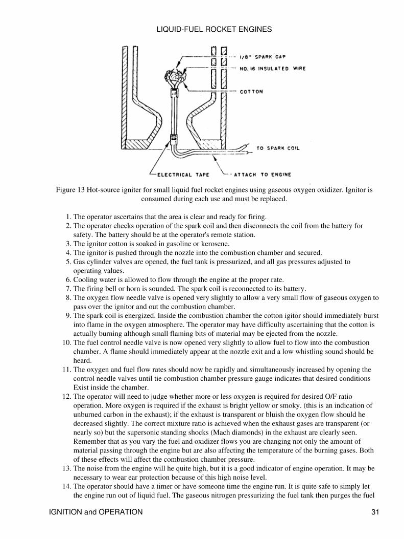
Figure 13 Hot-source igniter for small liquid fuel rocket engines using gaseous oxygen oxidizer. Ignitor isconsumed during each use and must be replaced.
The operator ascertains that the area is clear and ready for firing.1. The operator checks operation of the spark coil and then disconnects the coil from the battery forsafety. The battery should be at the operator's remote station.
2.
The ignitor cotton is soaked in gasoline or kerosene.3. The ignitor is pushed through the nozzle into the combustion chamber and secured.4. Gas cylinder valves are opened, the fuel tank is pressurized, and all gas pressures adjusted tooperating values.
5.
Cooling water is allowed to flow through the engine at the proper rate.6. The firing bell or horn is sounded. The spark coil is reconnected to its battery.7. The oxygen flow needle valve is opened very slightly to allow a very small flow of gaseous oxygen topass over the ignitor and out the combustion chamber.
8.
The spark coil is energized. Inside the combustion chamber the cotton igitor should immediately burstinto flame in the oxygen atmosphere. The operator may have difficulty ascertaining that the cotton isactually burning although small flaming bits of material may be ejected from the nozzle.
9.
The fuel control needle valve is now opened very slightly to allow fuel to flow into the combustionchamber. A flame should immediately appear at the nozzle exit and a low whistling sound should beheard.
10.
The oxygen and fuel flow rates should now be rapidly and simultaneously increased by opening thecontrol needle valves until tie combustion chamber pressure gauge indicates that desired conditionsExist inside the chamber.
11.
The operator will need to judge whether more or less oxygen is required for desired O/F ratiooperation. More oxygen is required if the exhaust is bright yellow or smoky. (this is an indication ofunburned carbon in the exhaust); if the exhaust is transparent or bluish the oxygen flow should hedecreased slightly. The correct mixture ratio is achieved when the exhaust gases are transparent (ornearly so) but the supersonic standing shocks (Mach diamonds) in the exhaust are clearly seen.Remember that as you vary the fuel and oxidizer flows you are changing not only the amount ofmaterial passing through the engine but are also affecting the temperature of the burning gases. Bothof these effects will affect the combustion chamber pressure.
12.
The noise from the engine will he quite high, but it is a good indicator of engine operation. It may benecessary to wear ear protection because of this high noise level.
13.
The operator should have a timer or have someone time the engine run. It is quite safe to simply letthe engine run out of liquid fuel. The gaseous nitrogen pressurizing the fuel tank then purges the fuel
14.
LIQUID-FUEL ROCKET ENGINES
IGNITION and OPERATION 31
supply system automatically. The engine will abruptly stop operation and the operator can then turnoff the flow of gaseous oxygen. If the engine is to be stopped prior to fuel depletion the fuel flowcontrol valve should be quickly turned off, followed by opening of the nitrogen purge valve. After theengine has stopped operation (thus assuring that the nitrogen purge has forced all fuel from theengine) the gaseous oxygen valve may be turned off. The nitrogen purge valve is closed, the cylindervalves are closcd, and the fuel tank vent valve opened. The oxygen line is vented by briefly openingthe oxygen flow need1e valve. Water should be allowed to flow through the engine cooling jacket forseveral minutes after run termination.In the event of engine failure, the shutdown sequence detailed in (14), above, should be followed.Always shut-off the liquid fuel first. If engine metal parts are burning, also immediately shut-off theflow of gaseous oxygen (metal will burn vigorously in an oxygen environment).
15.
A new ignitor will be required for each ignition attempt or firing. The ignitor assembly is partiallyconsumed during the ignition process and residue is quickly blown from the combustion chamberupon ignition of the liquid fuel.
16.
Always inspect the engine and other components for damage, apparent overheating or hot spots priorto another firing.
17.
Some engine designs may exhibit combustion instability (chugging, chuffing, erratic combustion,etc.) at low chamber pressures or low fuel injection velocities. To avoid this problem, the operatorshould rapidly increase the chamber pressure after initial introduction of the liquid fuel.
18.
Ignition and operation of small liquid-fuel rocket engines in the manner described offers the amateur arelatively safe and interesting activity. The operator will quickly discover and use many procedures toimprove engine and test stand operation.
After achieving initial operation of the engine and test stand, the amateur can begin to consider methods ofmeasuring engine thrust, determining the heat transfer to the cooling water, and noting the characteristics ofthe rocket engine exhaust. Photography of this exhaust is a definite challenge. As these additional features areadded to the experimertal set-up, the amateur should always keep safety and safe operating proceduresforemost in mind.
BIBLIOGRAPHY
The reader is urged to consult any of the following books for further information relating to rocket engines,materials, or design.
Rocket Propulsion Elements, by George P. Sutton. John Wiley & Sons, Inc., New York, 1964.• Design of Liquid, Solid, and Hybrid Rockets, by R. L. Peters. Hayden Book Co. Inc., New York,1965.
•
Elements of Flight Propulsion, by J. V. Foa. John Wiley & Sons, Inc., New York, 1960.• Rocket Propulsion, by M. Barrere and others. Elsevier Publishing Co., Netherlands 1960.• [Aerospace Propulsion, by Dennis G. Shepherd, Elsevier Publishing Company, 335 VanderbiltAvenue, New York, NY, 1972. ISBN 71-190302.]
•
Rocket Encyclopedia Illustrated. Aero Publishers. Inc., Los Angeles 26, California, 1959.• Thermodynamics, by Gordon J. Van Wylen. John Wiley & Sons, Inc., New York 1959.• Fluid Mechanics, by Victor L. Streeter. McGraw Hill Book Company, Inc., New York, 1966.• Heat Transmission, by W. H. McAdams. McGraw-Hill Book Company, Inc., New York, latestedition.
•
Design of Machine Elements, by M. F. Spotts. Prentice-Hall, Inc., Englewood Cliffs, N.J., 1955.• Mechanics of Materials, by Laurson & Cox. John Wiley & Sons, Inc., New York, 1955.• Stainless Steel Handbook, published by Allegheny Ludlum Steel Corp., Pittsburgh 22, Pa., 1959.•
LIQUID-FUEL ROCKET ENGINES
BIBLIOGRAPHY 32
Alcoa Aluminum Handbooks published by Aluminum Company of America. Pittsburgh. 1959.• Alcoa Handlbook of Design Stresses for Aluminum, published by Aluminum Company of America,Pittsburgh.
•
Matheson Compressed Gas Data Book, published by Matheson, P.O. Box 85 East Rutherford N.J.1966.
•
LIST of SUPPLIERS
The following list of suppliers is not complete since there are literally hundreds of companies in the UnitedStates manufacturing items of interest and use to the amateur rocket engine builder. The reader is urged toconsult his nearest city's telephone book Yellow Pages. Illustrated catalogs can be obtained by writing thecompanies listed below; ask for a current price list and the name of the nearest supplier.
Regulators
Grove Valve and Regulator Co.6 529 Hollis StreetOakland, California 94608
Victor Equipment Co.840-854 Folsom Street San Francisco, California 94107
The Harris Calorific Co.5501 Cass AvenueCleveland, Ohio 44102
Hoke Incorporated10 Tenakill ParkCresskill, New Jersey 07626
Needle Valves
Dragon Engineering Co.Excelsior Drive & CarmenitaP. O. 80x 489Norwalk, California 90650
Hoke Incorporated10 Tenakill ParkCresskill, New Jersey 07626
Republic Manufacturing, Co.15655 Brookpark RoadCleveland Ohio 44142
Robhins Aviation, lnc.3817 Santa Fe AvenueVernon, California 90058
Circle Seal Products Co., Inc.East Foothill Blvd. & Craig StreetPasadena, California 91107
LIQUID-FUEL ROCKET ENGINES
LIST of SUPPLIERS 33
Ball Valves
Hoke Incorporated10 Tenakill ParkCresskill, New Jersey 07626
Jamesbury Corporation669 Lincoln StreetWorcester, Massachusetts 01605
Hydromatics, Jnc.7 Lawrence StreetBloomfield, New Jersey 07003
Republic Manufacturing Co.15655 Brookpark RoadCleveland Ohio 44142
Check Valves
Circle Seal Products Co., Inc.East Foothill Blvd. & Craig StreetPasadena, California 91107
Republic Manufacturing Co.15655 Brookpark RoadCleveland, Ohio 44142
Hoke Incorporated10 Tenakill ParkCresskill, New Jersey 07626
Filters
Purolator Products, Inc.1000 New Brunswick AvenueRahway, New Jersey 07065
Hoke Incorporated10 Tenakill ParkCresskill, New Jersey 07626
Microporous Filter DivisionCircle Seal Development Corp.P. O. Box 3666Anaheim, California 92803
Relief Valves
Circle Seal Products Co., Inc.East Foothill Blvd & Craig StreetPasadena, California 91107
LIQUID-FUEL ROCKET ENGINES
LIST of SUPPLIERS 34
Hoke Incorporated10 Tenakill ParkCresskill, New Jersey 07626
Pressure Gauges
Helicoid Gage DivisionAmerican Chain & Cable Co.Connecticut Avenue & Hewitt StreetBridgeport, Connecticut 06602
United States Gauge DivisionAmerican Machine & Metals, Inc.Sellersville, Pennsylvania 18960
Marsh Instrument Co.3501 Howard StreetSkokie, Illinois 60076
Heise Bourdon Tube Co., Inc.1 Brook RoadNewtown, Connecticut 06470
O-Rings
Parker Seal Co.10567 Jefferson Blvd. Culver City, California 90230
Minnesota Rubber Co.3628 Wooddale AvenueMinneapolis, Minnesota 55416
Crush Gaskets
Gasket Manufacturing Co., Inc.319 West 17th StreetP. O. Box 15438Los Angeles, California 90015
Spray Nozzle
Delaval Manufacturing Co.Grand Avenue & 4th StreetWest Des Moines, Iowa 50265
Spraying Systems Co.3265 Randolph StreetBellwood, Illinois 60104
LIQUID-FUEL ROCKET ENGINES
LIST of SUPPLIERS 35
Tube Fittings
Parker Tube Fittings DivisionParker-Hannifin Corp.17327 Euclid AvenueCleveland, Ohio 44112
Imperial-Eastman Corp.6300 West Howard StreetChicago, Illinois 60648
Featherhead Co.320 East 131st StreetCleveland, Ohio 44108
Gas Cylinder Fittings
Western Enterprises, Inc.27360 West Oviatt RoadP. O. Box 9737Bay Village, Ohio 44140
Hoke Incorporated10 Tenakill ParkCresskill, New Jersey 07626
CONVERSION FACTORS
Multiply by To Obtain ----------------------------------------------- Btu/minute 0.02356 Horsepower
Btu/minute 17.57 Watts
Cubic feet 1728 Cubic inches
Cubic feet 7.48052 Gallons
Feet 12 Inches
Gallons 0.1337 Cubic feet
Gallons 231 Cubic inches
Gallons water 8.3453 Pounds water
Miles 5280 Feet
Miles/hour 1.467 Feet/sec
Minute 60 Seconds
Pounds 16 Ounces
Pounds water 0.1198 Gallons
Square feet 144 Square inches
LIQUID-FUEL ROCKET ENGINES
LIST of SUPPLIERS 36
Temp (degC + 17.78) 1.8 Temp (degF)
Temp (degF + 460) 1 Abs. Temp (degR)
Temp (degF - 32) 5/9 Temp (degC)
Additions and Corrections
The Atlas is no longer a "missile" but has been converted into a "space launch vehicle".• The calculation in the Propellant Choice section assumes that there are no losses; i.e., that the"maximum theoretical" Isp will be that which is achieved. There are numerous loss terms notaccounted for; hence the flowrate given is incorrect.
•
Modern launch vehicles operate fuel rich as stated; however it is not due to a desire to reduce thecombustion temperature. Rather, the kinetic losses (losses due to departure from full shiftingequilibrium) are a maximum at stoichiometric; the prudent designer therefore selects a mixture ratio"off stoichiometric" in order to minimize the kinetic losses.
•
The Test Stand section, asserts that electrical instrumentation wherein a transducer is located on thetest stand and an electrical readout is located on the operator's station is too expensive for mostamateurs. This is no longer the case. Actuated valves, pressure transducers, etc. and analog-to-digitalcapture systems for personal computers are very reasonable in price. Furthermore, a computer basedsystem can provide a complete sensor log for the entire run, that will be extremely valuable indiagnosing failure and evaluating performance.
•
In the example calculation, I think there may be arithmetic errors in the calculation of the coolant flowgap. Readers are strongly encouraged to redo all calculations for themselves.
•
According to John F. Cox <[email protected]>:
There is a small technical error in the "Heat Transfer" section of the amateur rocket designer's text. Atthe end of this section the author advises that:
Material failure is usually caused by either raising the wall temperature on the gas side so as toweaken, melt, or damage the wall material or by raising the wall temperature on the liquid coolantside so as to vaporize the liquid next to the wall. The consequent failure is caused because of the sharptemperature rise in the wall caused by exessive heat transfer to the boiling coolant.
Boiling is usually a good thing from the standpoint of heat transfer. The author has it right that boilingusually increases the heat transfer. Increased heat transfer, however, results in lowered temperature.Think about that for a minute and it will become obvious.
The problem with boiling in this application results from something that is called alternately filmboiling, jacket boiling, or Liedenfrost boiling. The boiling rate becomes so intense that a layer ofvapor is established between the hot wall and the cool liquid. The heat transfer properties of boilingliquid are really wonderful. The heat transfer properties of gaseous vapor really suck. Once the vaporbarrier is established, whatever it is that is being cooled will likely melt.
•
Other Notices
Reprinted with permission.
This book has been out of print and very hard to find for many years. For this reason, I decided to undertake
LIQUID-FUEL ROCKET ENGINES
CONVERSION FACTORS 37
the task of putting it into electronic media for wider dissemination. If you need to contact me about this book,please email me, [email protected].
The book was scanned from a copy provided to me by the generosity and foresight of Wayne Gramlich ofSun. Numerous errors were introduced by the scanning and OCR process that I and other volunteers removedby hand. Special thanks goes to Jim Glass of Rocketdyne for his outstanding efforts.
LIQUID-FUEL ROCKET ENGINES
Other Notices 38