Liquid Crystal Self-Assembly and Organic Inorganic Hybrid ...
84
Liquid Crystal Self-Assembly and Organic–Inorganic Hybrid Material Design Pouya Moghimian Dissertation submitted as a requirement for the degree of Doctor of Philosophy January 2017 – Technical University of Darmstadt (TUD) – D17
Transcript of Liquid Crystal Self-Assembly and Organic Inorganic Hybrid ...

Liquid Crystal Self-Assembly and
Organic–Inorganic Hybrid
Material Design
Pouya Moghimian
Dissertation submitted as a requirement for the degree of Doctor of Philosophy
January 2017 – Technical University of Darmstadt (TUD) – D17

2

3
Liquid Crystal Self-Assembly and
Organic–Inorganic Hybrid Material Design
Dissertation Approved by the Department of Materials and Earth Sciences
in Fulfillment of the Requirements for the Degree of
Doctor of Philosophy (Dr. rer. nat.)
By
Pouya Moghimian
Max Planck Institute for Solid State Research
B.Eng. Ceramics Engineering 2011, M.Sc. Advanced Materials 2013
Born in Tehran
Technische Universität Darmstadt, Hochschulkennziffer D17
Place of Publication: Darmstadt
Year of Publication: 2017
Date of Submission: October 24, 2016
Date of Oral Examination: January 17, 2017
Certified by
Peter A. van Aken
Professor of Geo-Material Science
Max Planck Institute for Solid State Research
Referee
Certified by
Hans-Joachim Kleebe
Professor of Geo-Material Science
Technical University of Darmstadt
Co-Referee
4
Liquid Crystal Self-Assembly and Organic–Inorganic Hybrid Material Design
By
Pouya Moghimian
Submitted to the Department of Materials and Earth Sciences on October 24th, 2016
in Partial Fulfillment of the Requirements for the Degree of
Doctor of Philosophy in Materials Science
ABSTRACT
Viruses offer promising applications in virotronics (virus-based technology) and as soft
scaffolds for building intelligent (i.e. responsive) multicomponent materials. The Ff class of phages
including M13 and fd phages have recently received high attention due to their high uniformity and
monodispersity. Phages have been used in virus-based applications owing to their low cost production,
mild working temperature and pH conditions, chemical modifiability and ease of manipulation. In
addition, they were found to exhibit liquid crystalline behavior in solutions; a property that made rod-
like phages suitable material for self-assembly and soft matter physics. All of these features brought
phages in the center of focus for the use in diverse applications such as semiconductors, chemical and
biological sensing and piezoelectric nanogenerators.
Spontaneous assembly of anisometric colloidal particles, such as rod-like M13 phages, in two-
dimensions (2D) can be carried out via evaporation of the colloid-containing suspensions on solid
substrates. Rod-like particles having a high aspect ratio (e.g. very long inoviruses) show liquid crystal
(LC) behavior in suspensions and they can be treated as polymer chains composed of homogenous
elastic material, where the persistence length characterizes the molecular stiffness. Therefore,
suspensions containing M13 phages are considered to be ideal model systems for studying the
properties of soft matter systems. Here, I designed an experiment in order to obtain a condition in
which filamentous M13 phages have a high degree of alignment along a common axis on a solid
substrate. One aim is to attain a fully covered surface with densely packed and highly oriented M13
phage particles. Moreover, the effect of substrate surface chemistry on the alignment and orientation
of macromolecules was investigated. Our results suggest an approach that can be used to immobilize
oriented viral arrays on amorphous carbon surface. A unique feature of our approach is that the
aforementioned architectures can be obtained by applying phage solution on a surface without
employing nanoparticle assembly methods such as dip coating or convective assembly. However, an
ordered medium of liquid crystals often possesses a variety of defects and deformations, at which the
director n(r) of the liquid crystal undergoes an abrupt change compared to the vicinity of the defect.
Experimental research on these effects has been remained challenging and been barely performed on
confined rod-like colloidal particles on structured surfaces. Therefore, I intend to investigate the local
deformation of rod-like M13 phage particles resulting from confinement in an irregular stranded web
of thin carbon film and compare them to the existing theories. I shift the focus from evaporative self-
organization on rationally designed surfaces to that on a complex surface. The aim is to study the
possibility of controlling the orientation of M13 phages in two-dimensional nematic films by choosing
structured substrates.
These rod-like molecules have the ability to mineralize a variety of inorganic materials. They
can be used for the controlled growth of inorganic materials and for the production of hybrid
structures. Owing to this property, phages are in the center of attention for the selected deposition and
5
mineralization of inorganic substances. Here, I use M13 phages to mineralize zinc oxide nanoparticles
from a deposition solution. This allowed us to construct nano-hybrid layered materials consisting of
alternating organic (M13 phage) and inorganic (zinc oxide) layers (layer-by-layer) on a silicon
substrate. Our aim is to achieve a homogeneous and uniform phage-assisted assembly of layered
structures and to determine their microstructure, elemental composition and homogeneity. These
hybrid structures have a potential for the use in biotechnology such as organic electronics.
6
ZUSAMMENFASSUNG
Viren bieten vielversprechende Anwendungen in „Virotronics“ (Virus-basierte Technologie)
und als weiche Gerüste für den Aufbau intelligenter mehrkomponentiger Materialien. Die Ff Klasse
von Phagen einschließlich M13 und fd Phagen haben vor kurzem hohe Aufmerksamkeit wegen ihrer
hohen Gleichmäßigkeit und Monodispersität erlangt. Materialwissenschaftler und chemische Biologen
haben Phagen in Virus-basierten Anwendungen aufgrund ihrer geringen Produktionskosten, milden
Temperatur und pH-Bedingungen, chemischen Modifizierbarkeit und Leichtigkeit der Manipulation
verwendet. Darüber hinaus wurde ein flüssigkristallines Verhalten in Lösungen nachgewiesen; eine
Eigenschaft, die stabförmige Phagen zu einem geeigneten Material für Selbstorganisation und der
Physik der weichen Materie macht. Alle diese Merkmale brachten Phagen in den Fokus für den
Einsatz in verschiedenen Anwendungen, wie beispielsweise Halbleiter Technologie, Chemo- und
Biosensoren und piezoelektrische Nanogeneratoren.
Den spontanen Zusammenbau von anisometrischen kolloidalen Teilchen, wie stabförmige
M13 Phagen, in zwei Dimensionen (2D) kann über Verdampfung der kolloidhaltigen Suspensionen
auf festen Substraten durchgeführt werden. Stabförmige Teilchen mit einem hohen Aspektverhältnis
(beispielsweise sehr lange „Inoviruses“) zeigen flüssigkristallines (LC) Verhalten in Suspensionen und
sie können als Polymerketten behandelt werden, die aus homogenen elastischen Material bestehen,
wobei die Persistenzlänge des Moleküls seine Steifigkeit auszeichnet. Daher werden Suspensionen,
die M13 Phagen enthalten, als ideale Modellsysteme für das Studium der Eigenschaften weicher
Materie angesehen. Hier entwickelte ich ein Experiment, um einen Zustand zu erhalten, in dem
filamentöse M13 Phagen einen größtmöglichen Grad der Ausrichtung entlang einer gemeinsamen
Achse auf einem Substrat aufweisen. Ein Ziel ist es, eine Oberfläche zu erreichen, die mit dicht
gepackten und gleichförmig ausgerichteten M13 Phagen möglichst vollständig bedeckt ist. Darüber
hinaus wurde die Auswirkung der Substratoberflächenchemie auf die Ausrichtung und Orientierung
der Makromoleküle untersucht. Unsere Ergebnisse deuten darauf hin, dass dieser Ansatz, dazu
verwendet werden kann, orientierte virale Felder auf amorpher Kohlenstoffoberfläche zu
immobilisieren. Ein besonderes Merkmal unseres Ansatzes ist, dass die oben genannten Strukturen
durch Aufbringen einer Phagenlösung auf einer Oberfläche ohne den Einsatz von auf Nanopartikeln
basierenden Montageverfahren wie „dip coating“ oder „convective assembly“ erhalten werden
können. Jedoch besitzt ein geordnetes Medium von Flüssigkristallen häufig eine Vielzahl von
Fehlstellen und Deformationen, wo der Direktor n(r) des Flüssigkristalls eine abrupte Änderung im
Vergleich zu der Umgebung des Defektes erfährt. Experimentelle Forschung über diese Effekte sind
noch immer eine große Herausforderung und wurde nur selten an beschränkten, stabförmigen,
kolloidalen Teilchen auf strukturierten Oberflächen durchgeführt. Deshalb will ich die lokale
Verformung von stabförmigen M13 Phagen untersuchen, die sich aus der Umgebung in einem
unregelmäßigen Netz von dünnen Kohlenstoff Filmen ergibt und diese mit den existierenden Theorien
vergleichen. Ich verschiebe den Fokus von Verdunstungsselbstorganisation auf rational designten
Oberflächen zu der auf einer komplexen Oberfläche. Das Ziel ist es, die Möglichkeit einer Steuerung
der Orientierung von M13 Phagen in 2D nematischen Filme zu untersuchen, indem strukturierte
Substrate verwendet werden.
Diese stabförmigen Moleküle haben die Fähigkeit, eine Vielzahl von anorganischen
Materialien zu mineralisieren. Sie können für das kontrollierte Wachstum von anorganischen
Materialien verwendet werden, um Hybridstrukturen zu produzieren. Aufgrund dieser Eigenschaft
sind Phagen in den Mittelpunkt der Aufmerksamkeit für die gezielte Ablagerung und Mineralisierung
von anorganischen Substanzen gerückt. Hier verwende ich M13 Phagen, um Zinkoxid Nanopartikel
7
aus einer Abscheidungslösung zu mineralisieren. Dies erlaubte uns, Nanohybridmaterialien zu
konstruieren, die aus alternierenden organischen (M13 Phagen) und anorganischen (Zinkoxid) Schicht
(„layer-by-layer“) auf einem Substrat bestehen. Unser Ziel ist es, eine homogene und einheitliche
Phagen-gestützte Anordnung von Schichtstrukturen zu erreichen und ihre Mikrostruktur, elementare
Zusammensetzung und Homogenität zu bestimmen. Diese Hybridstrukturen haben ein Potenzial für
den Einsatz in der Biotechnologie wie die organische Elektronik.
8
THESIS SUPERVISORS
Prof. Dr. Peter A. van Aken
Professor of Geo-Material Science
Stuttgart Center for Electron Microscopy (StEM)
Max Planck Institute for Solid State Research
Prof. Dr. Hans-Joachim Kleebe
Professor of Geo-Material Science
Geo- and Material Sciences Department
Technical University of Darmstadt
THESIS COMMITTEE
Prof. Dr. Peter A. van Aken
Referee
Professor of Geo-Material Science
Geo- and Material Sciences Department
Technical University of Darmstadt
Prof. Dr. Hans-Joachim Kleebe
Co-referee
Professor of Geo-Material Science
Geo- and Material Sciences Department
Technical University of Darmstadt
Prof. Dr. Wolfram Jägermann
Examiner
Professor of Materials Science
Materials Science Department
Technical University of Darmstadt
Prof. Dr. Jörg J. Schneider
Examiner
Professor of Chemistry
Inorganic Chemistry Department
Technical University of Darmstadt

9
To my parents, Jamileh and Ahmad
who always believed in me all the way;
To my brother, Nima, for his encouragement
and caring guidance in all ways

10
ACKNOWLEDGMENTS
First of all, I sincerely express my deepest gratitude to my thesis supervisors, Prof. Dr. van
Aken and Prof. Dr. Hans-Joachim Kleebe. I am grateful to both of them for guiding and encouraging
me throughout my doctoral study and for giving me the opportunity to develop my own ideas. I have
always appreciated and admired Prof. van Aken’s leadership and Prof. Kleebe’s knowledge and
approachable personality. I have equally enjoyed working with Vesna because of her kindness,
support and enthusiasm. I feel lucky for having been part of their research group. I would like to thank
my thesis committee members, Prof. Dr. Wolfram Jägermann, and Prof. Dr. Jörg J. Schneider for the
insightful discussions on my work that gave me a new perspective.
I pay my compliments and express my debt to Dr. Ludger Harnau (MPI-IS) both as a mensch
and as a distinguished scholar in Physics, who inspired me most and initiated me into the study of
condensed matter physics.
I would like to gratefully acknowledge all the members of StEM for bringing so much joy and
for encouraging and caring words. I would also like to thank several mentors that helped me with
laboratory techniques and instrument use, especially at the beginning and also throughout my Ph.D.;
In the TEM sample preparation lab, Ute Salzberger and Marion Kelsch taught me sample preparation
methods beside tripod polishing technique and ion milling. In the TEM labs, Kersten Hahn and Peter
Kopold for tutoring me in electron microscopy techniques. In the SEM labs, Felicitas Predel for
teaching me SEM techniques. Ulrike Eigenthaler for preparing TEM samples by FIB. In the Biolabs,
my dearest mentor and friend Sandra J. Facey for providing me viral solutions and for the fruitful
discussions. Dirk Rothenstein for teaching me drop casting method. Thanks also to Stefan Kilper for
sharing his knowledge of the organic–inorganic layer-by-layer assembly with me and several other
techniques related to thin films. Joachim Spatz for the allowance to use his biolabs and Christine
Mollenhauer for providing all the biolab equipment and for her support during the experiments. Petia
Atanasova for her contribution to my knowledge about the organic–inorganic structures. In particular,
I would like to thank especially my dear colleagues and friends, Nilesh Vats, Surong Guo, Iman
Rastegar, Nima Farhmand Bafi, Mahdieh Schmidt and Robin Lingstädt. They have been absolutely
helpful with research, and their presence also made my days more pleasant. Especially, I would like to
sincerely thank Jana Rein who was continuously there beside me all the way.
I have also had the opportunity and honor to work with other very helpful collaborators, who
helped me with measurements for my project or kindly offered help with different tasks; Benoit P.
Pichon from the University of Strasbourg who gave me amazing ideas in our project and initiated the
study of organic and magnetic inorganic hybrid materials. Francisco de la Peña from the University of
Cambridge who helped me tremendously with image analysis. Markus Bier, Mykola Tasinkevych and
Nima Farahmand Bafi, from the Theory of Inhomogeneous Condensed Matter group (MPI-IS) for
discussions and the help with data analysis. I would like to acknowledge, in particular, the help offered
by Alison F. Mark from StEM. She was very generous with her time, and her ideas and expertise were
extremely useful for developing my work. I also want to highlight the contribution of StEM
administrative assistant, Caroline Heer, who has been tremendously helpful with scheduling and
simply for her care.
I would like to sincerely acknowledge the financial support by the German Research
Foundation (DFG). The research leading to our results has received funding from the European Union
Seventh Framework Programme [FP7/2007-2013] under grant agreement no. 312483 (ESTEEM2).
I could not thank enough my family, whose love and guidance carried me through this
process. You have been my greatest inspiration and I could not have finished this thesis without you.
11
BIOGRAPHICAL NOTE
EDUCATION
Ph.D. Max Planck Institute for Solid State Research
Technical University of Darmstadt (TUD)
2013–2017
Materials Science
Supervised by,
Prof. Dr. Peter A. van Aken
Prof. Dr. Hans-Joachim Kleebe
M.Sc. University of Ulm
Advanced Materials –Biomaterials–
2011–2013
Supervised by,
Prof. Dr. Ute Kaiser
Prof. Dr. Peter A. van Aken
B.Eng. Iran University of Science & Technology (IUST)
Ceramics Engineering
2006–2011
Supervised by,
Prof. Dr. Jafar Javadpour
HONORS AND AWARDS
Awarded as “Recognized Reviewer” by the journal of Powder Technology (Elsevier) and the journal
of Materials Science & Engineering C (Elsevier)
PUBLICATIONS
Papers
P. Moghimian, V. Srot, B. P. Pichon, S. J. Facey, P. A. van Aken, “Stability of M13 Phage in Organic
Solvents”, Journal of Biomaterials and Nanobiotechnology, 2016, 7 (2), 72-77.
P. Moghimian, L. Harnau, V. Srot, F. de la Peña, N.F. Bafi, S. J. Facey, P. A. van Aken, “Controlled
Self-Assembly of Biomolecular Rods on Structured Substrates”, Soft Matter, 2016, 12 (13), 3177-
3183.
P. Moghimian, S. Kilper, V. Srot, D. Rothenstein, S. J. Facey, B. Hauer, J. Bill, P. A. van Aken,
“Phage-Assisted Assembly of Organic-Inorganic Layered Hybrid Structures”, International Journal of
Materials Research (IJMR), 2016, 107 (4), 295-299.
P. Moghimian, V. Srot, D. Rothenstein, S. J. Facey, L. Harnau, B. Hauer, J. Bill, P. A. van Aken,
“Adsorption and Self-Assembly of M13 Phage into Directionally Organized Structures on C and SiO2
Films”, Langmuir, 2014, 30 (38), 11428-11432.
P. Moghimian, A. Najafi, S. Afshar, J. Javadpour, “Effect of low temperature on formation mechanism
of calcium phosphate nano powder via precipitation method”, Advanced Powder Technology, 2012, 23
(6), 744-751.
12
Conferences
V. Srot, B. Bussmann, U. Salzberger, P. Moghimian, M. Espanol, B. Hauer, P. A. van Aken,
“Investigations of Sensitive Composite Organic-Inorganic Materials by Analytical (S)TEM” (oral),
Materials Science Engineering (MSE) Congress, September 2016, Darmstadt, Germany.
P. Moghimian, L. Harnau, V. Srot, F. de la Peña, N.F. Bafi, S. J. Facey, P. A. van Aken, “Colloidal
Rods in Irregular Spatial Confinement” (poster), The 16th European Microscopy Congress (EMC),
August 2016, Lyon, France.
P. Moghimian, V. Srot, L. Harnau, D. Rothenstein, S. J. Facey, B. Hauer, J. Bill, P. A. van Aken,
“Assembly of Semi-Flexible Macromolecules and Defect Formation in Colloid Ordering in Non-
Symmetric Geometries” (oral), Materials Research Society (MRS) Fall Meeting, November 2015,
Boston, MA, USA.
P. Moghimian, V. Srot, D. Rothenstein, S. J. Facey, L. Harnau, S. Kilper, B. Hauer, J. Bill, P. A. van
Aken, “Phage-Controlled Assembly of Organic-Inorganic Hybrid Layered Structures” (poster),
Microscopy Conference 2015 (MC 2015) , September 2015, Göttingen, Germany.
P. Moghimian, V. Srot, D. Rothenstein, S. J. Facey, B. Hauer, J. Bill, T. Schimmel, P. A. van Aken,
“From Ultrathin Assembled Viral Films to Organic-Inorganic Multilayered Structures” (oral),
European Materials Research Society (E-MRS), May 2015, Lille, France.
P. Moghimian, V. Srot, D. Rothenstein, S. J. Facey, P. A. van Aken, “Adsorption and self-assembly of
M13 phage into directionally organized structures on C and SiO2 thin films” (oral), Materials Science
Engineering (MSE) Congress, September 2014, Darmstadt, Germany.
P. Moghimian, V. Srot, D. Rothenstein, S. J. Facey, P. A. van Aken, “Induced assembly of M13 phage
arrays using carbon thin films” (poster). 18th International Microscopy Conference, September 2014,
Prague, Czech.
P. Moghimian, J. Javadpour, S. Afshar, A. Talimian, “An investigation on the phase evolution of
calcium phosphate ceramics at low temperatures” (poster), 29th Annual Conference of the Canadian
Biomaterials Society, Poster Presentation, Vancouver, BC, Canada.
P. Moghimian, M.H. Khosravi, J. Javadpour, M. Samadani, “A Novel Route for Producing Desired
Biphasic Calcium Phosphates” (poster), 8th Congress of Iranian Ceramic Society, May 2011, Tehran,
Iran.
13
Contents
ABSTRACT ........................................................................................................................................... 4
ZUSAMMENFASSUNG ....................................................................................................................... 6
ACKNOWLEDGMENTS ................................................................................................................... 10
BIOGRAPHICAL NOTE ................................................................................................................... 11
Contents ................................................................................................................................................ 13
1. Chapter 1. Introduction and Motivation ................................................................................... 15
1.1. Bacteriophages ...................................................................................................................... 15
1.1.1. M13 Phage ..................................................................................................................... 16
1.2. Liquid Crystals and Self-Assembly ....................................................................................... 18
1.2.1. Liquid Crystals Fundamentals ....................................................................................... 18
1.2.2. Textures and Defects in Liquid Crystals ....................................................................... 19
1.3. Bio-Inspired Organic–Inorganic Hybrid Structures .............................................................. 22
1.3.1. Biomineralization of Zinc Oxide ................................................................................... 23
1.4. Thesis objectives and Structure ............................................................................................. 23
2. Chapter 2. Characterization and Experimental Techniques ................................................... 25
2.1. Scanning Electron Microscopy .............................................................................................. 26
2.1.1. Principles of SEM ......................................................................................................... 26
2.1.2. Interaction of Electrons with a Solid ............................................................................. 27
2.1.3. Secondary-Electron Images ........................................................................................... 28
2.1.4. SEM Sample Preparation .............................................................................................. 29
2.2. Transmission Electron Microscopy ....................................................................................... 30
2.2.1. Principles of TEM ......................................................................................................... 30
2.2.2. Scanning TEM (STEM) ................................................................................................ 34
2.2.3. TEM Specimen Preparation .......................................................................................... 36
2.3. Atomic Force Microscopy ..................................................................................................... 38
2.4. Contact Angle Goniometry.................................................................................................... 39
2.5. Phage Propagation and Purification ...................................................................................... 40
2.6. Convective Assembly Technique .......................................................................................... 41
3. Chapter 3. Stability and Structural Integrity of M13 Phages ................................................. 43
3.1. Abstract ................................................................................................................................. 43
3.2. Introduction ........................................................................................................................... 44
3.3. Materials and Methods .......................................................................................................... 44
3.4. Results and Discussion .......................................................................................................... 45
3.5. Conclusions ........................................................................................................................... 47
14
4. Chapter 4. Adsorption and Self-Assembly of M13 Phages on Solid Surfaces ....................... 48
4.1. Abstract ................................................................................................................................. 48
4.2. Introduction ........................................................................................................................... 49
4.3. Materials and Methods .......................................................................................................... 49
4.4. Results and Discussion .......................................................................................................... 50
4.5. Conclusions ........................................................................................................................... 54
5. Chapter 5. Ordering of Biomolecular Rods on Complex Geometries .................................... 55
5.1. Abstract ................................................................................................................................. 55
5.2. Introduction ........................................................................................................................... 56
5.3. Materials and Methods .......................................................................................................... 56
5.4. Bending Energy of Two-Dimensionally Confined Macromolecules .................................... 57
5.5. Results and Discussion .......................................................................................................... 59
5.6. Conclusions ........................................................................................................................... 63
6. Chapter 6. Biomineralization and Biotemplated Synthesis of Organic–Inorganic Hybrid
Multilayers ........................................................................................................................................... 65
6.1. Abstract ................................................................................................................................. 65
6.2. Introduction ........................................................................................................................... 66
6.3. Materials and Methods .......................................................................................................... 66
6.4. Results and Discussion .......................................................................................................... 67
6.5. Conclusions ........................................................................................................................... 71
7. Chapter 7. Conclusions and Future Directions ........................................................................ 72
7.1. Concluding Remarks ............................................................................................................. 72
REFERENCES .................................................................................................................................... 77

15
1. Chapter 1. Introduction and
Motivation
1.1. Bacteriophages
Bacteriophages or phages are viruses infecting bacterial host cells.1,2 The name “bacteriophage”
is a synonym of “bacteria eater” implying that once a bacteriophage infects the bacterial host, the virus
uses the resources of the bacterial host cell to fabricate many copies of itself (i.e. to replicate).3,4
Phages are among the most common organisms on earth. They constitute a protein capsid surrounding
and guarding the genomic material (deoxyribonucleic acid (DNA) or ribonucleic acid (RNA)) in a
single-stranded (ss) or double-stranded (ds) form.2 There are many different kind of phages, each
having different DNA/RNA, replication processes, and morphologies.1 Different groups of phages
having different genomic material and morphology are shown in Table 1.
Table 1.1. Different groups of phages classified according to their morphology and genomic material.5
Phage Group Phage Type Member Morphology Genome
Inoviridae M13, fd, f1 Rod-like ssDNA
Myoviridae T4, P1, P2 Tailed (long contractile
tails) dsDNA
Podpviridae T7, P22 Tailed (short contractile
tails) dsDNA
Siphoviridae λ, T1, T5 Tailed (long non-
contractile tails) dsDNA
Corticoviridae PM2 Isometric dsDNA
Leviviridae MS2 Icosahedral ssDNA
One important group having single-stranded DNA genomes (inoviridae) appears as long
filamentous particles. Phages can be lysogenic or lytic with regard to their replication processes.2,6
Lysogenic phages inject their genomic materials infecting the host cells. The genetic materials
(DNA/RNA) uptake the host cell biosynthetic materials and reproduce the same genetic materials and
proteins. Thereafter, the produced proteins are conveyed to the host cell membranes, where new
phages, without disruption of the host cell walls, are loaded and released. In contrast, some phages
undergo lytic infectious cycles that are replicated and in-grouped inside the host cells rather than at the
cell membrane.6 When the replication process is accomplished, the newly amplified phages break the
host cell wall and are able to infect other host cells. The infection here results in a fast lysis of the cell
within a short time (typically within minutes or hours). The process of releasing of new infectious
viruses can be repeated as long as a sufficient number of bacterial hosts are present to support
replication.3 All phages have the ability to produce exact copies of themselves within completely
credible structural exactness, regardless of differences in shape, composition and life cycle.1,2 It has

16
been reported that temperature and pH are two important factors influencing not only the phage
infection but also the host cell growth.7 There are different morphologies of phages such as
filamentous (M13, fd) or icosahedral phages (MS2) (Figure 1.1a-c). There are some sophisticated
phage morphologies such as T4 phages that possess a head-tail structure with a cylindrical body (see
Figure 1.1b). The length of the packaged DNA is a dominant factor on determining the length of the
phages.8 The Ff class of phages (M13, fd and f1 phages) have been in wide use for a variety of
applications in biotechnology as biomimetic matrix for tissue engineering and also as biological
templates for material design.9 Phages offer nanoscale scaffolds for the construction of hybrid and
complex structures for optical or electronic applications. Their shape, monodispersity and anisotropy
provides material scientist with modifiable surfaces for the fabrication of such hybrid structures.
Owing to these features, phages are great candidates for the development of novel bionanomaterials.
Figure 1.1. Schematic illustration of different phages morphologies. (a) Schematic diagram of rod-like structure
of a filamentous M13 phage. (b) A T4 phage with connected head-tail structure having a cylindrical body. (c) A
MS2 phage with an icosahedral structure. Adapted from Ref. 2, Copyright 2011, with permission from Elsevier.
Besides, phages play important roles in biology and ecology.6 These include the use of phages
as molecular model in the study of organismal ecology and evolutionary biology, as molecular tools
(including phage display technologies) or indicators and tracers and their use in bacterial
identification.1,6
1.1.1. M13 Phage
M13 phage is a negatively charged and non-pathogenic virus. It has a long filamentous shape
that is approximately 880 nm in length and 6.6 nm in diameter with an aspect ratio 𝐿 𝑑 ≈ 130⁄ ,
(where L is its contour length and d is its diameter).10,11,12 The M13 phage shows liquid crystalline
behavior in suspensions owing to its high aspect ratio.13,14 M13 phages are categorized under the Ff
class of inoviruses (M13, fd, f1) that have been the focus of extensive research due to their capability
of self-assembling into liquid crystal structures. The M13 phage is stable under a wide range of
temperatures (between 90 °C and –20 °C) and pH values (between 2 and 9) and therefore has attracted
attention for the use in technological applications.9,15,16 The virus body consists of ~2700 identical

17
copies of the helically arranged major coat protein pVIII, which exhibits chemical specificity to some
inorganic materials.17,18 It also contains a smaller number of different minor coat proteins at its ends;
5-7 copies per particle of the minor coat proteins, pIII, pVI, pIX, and pVII.1,7,15,19 pIII and pVI are
located at one end, while the pIX and pVII cap the other end (see Figure 1.2a). The major capsid
protein wraps around an ssDNA. A schematic illustration of the major coat protein subunits having
five-fold helical symmetry (72 degrees of rotational symmetry around the central helical axis) is
shown in Figure 1.2b. The proteinaceous coat provides the structural stability, while pIII is necessary
for host cell recognition and infection, and therefore is required for the initiation of assembly. pIII is
the largest (406 amino acids) coat protein, which contains three distinct domains and therefore is
considered as the most complex coat protein.2,20
Figure 1.2. Schematic illustration of (a) M13 phage coat proteins 21 and (b) helically arranged major coat protein
(pVIII) subunits having five-fold symmetry (i.e. the angle between the red or green arrows is 72 degrees).
Adapted by permission from Macmillan Publishers Ltd: Nature, Ref. 14, copyright 2011, and from Ref. 21,
copyright 2012, from the Chemical Society of Japan and Wiley-VCH, Weimheim.
The pVIII coat protein of M13 virus is comprised of 50 amino acid residues in a sequence that
has a highly hydrophobic core and a negatively charged N-terminal domain and a basic positively
charged C-terminal region (see Figure 1.3).22 The N-terminal domain translocates the viral DNA
during infection into the Escherichia coli (E. coli).4 The C-terminal domain deals with the interaction
with other phage coat proteins, and is thus responsible for the integration of pIII into the phage body.19
The M13 phage is sorted in the non-lytic bacterial virus category, implying that it does not destroy the
bacterial cell membrane upon release, but instead is secreted through a protein pore channel in the
bacterial membrane.2 Due to the increased phage demands of metabolism during phage production,
bacterial host growth is lowered down but continues after infection. These properties enable
bacteriophage mass amplification in bacterial culture.4 Over the past two decades, owing to the phage
genetic engineering and approaches of synthesizing site specific organics, the phage biochemical
structure has been greatly flourished.19,23 By exploitation of genetic engineering, each sequence of coat
proteins can be modified by altering the viral DNA or integrating foreign DNA into phage genome.20
18
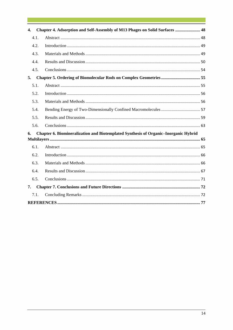
In phage-display technique, combinatorial peptides can be expressed as fusions to a capsid protein
(e.g. pIII or pVIII) on the surface of viral particles. In this method, the M13 phage has been the most
commonly used vector.21 Using phage-display technique the expressed peptide or proteins can have
interactions with desired targets in a way that the recombinant viral particles are stable. pIII and pVIII
have been mostly used to display peptides.21
Figure 1.3. (a) Schematic side-view of a single pVIII (p8) subunit showing the exterior solvent-accessible domain
(N-terminal), the hydrophobic core and the basic interior domain (C-terminal). (b) Schematic axial view of a the
assembly of p8 subunits in a phage particle. Reprinted with permission from Ref. 24, Copyright 2014, Taylor &
Francis.
Additionally, novel reactions that allows for site-specific modification of phage body with
chemicals such as fluorescent dyes or chromophores for various applications including biochemical
imaging and energy harvesting have been developed.1,2
1.2. Liquid Crystals and Self-Assembly
1.2.1. Liquid Crystals Fundamentals
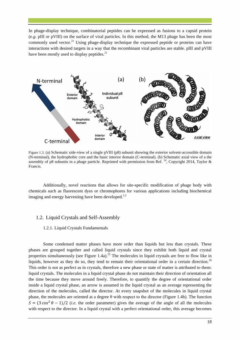
Some condensed matter phases have more order than liquids but less than crystals. These
phases are grouped together and called liquid crystals since they exhibit both liquid and crystal
properties simultaneously (see Figure 1.4a).25 The molecules in liquid crystals are free to flow like in
liquids, however as they do so, they tend to remain their orientational order in a certain direction.26
This order is not as perfect as in crystals, therefore a new phase or state of matter is attributed to them:
liquid crystals. The molecules in a liquid crystal phase do not maintain their direction of orientation all
the time because they move around freely. Therefore, to quantify the degree of orientational order
inside a liquid crystal phase, an arrow is assumed in the liquid crystal as an average representing the
direction of the molecules, called the director. At every snapshot of the molecules in liquid crystal
phase, the molecules are oriented at a degree θ with respect to the director (Figure 1.4b). The function
𝑆 = (3 cos2 𝜃 − 1)/2 (i.e. the order parameter) gives the average of the angle of all the molecules
with respect to the director. In a liquid crystal with a perfect orientational order, this average becomes

19
1 and in a liquid crystal with no orientational order this function gives an average of 0. The average of
the aforementioned function is called the order parameter (S). We should keep in mind that these
arrangements occur in three dimensions in a bulk liquid crystal.
Figure 1.4. Schematic illustrations of (a) solid, liquid crystal and liquids phases of matter. (b) A snapshot of the
molecules in a liquid crystal phase showing a preferred degree of orientation of the molecules (having an angle
θ) according to the dashed arrow (the director). 26
The liquid crystals are generally divided into two categories: the thermotropics and the
lyotropics. The thermotropic liquid crystal phases are formed by a change of temperature, and the
lyotropic liquid crystal phases are influenced by the concentration of the solvent. The lyotropics (e.g.
M13 or fd filamentous viruses) that show different phases according to their concentration are of high
interest in biological studies.27 The thermotropics are generally distinguished with respect to the shape
of the constituent molecules, being called calamatic for rod-like and discotic for disk-like
molecules.28,29 To date, there have been more than 80,000 different reported compounds that showed
liquid crystal properties.28
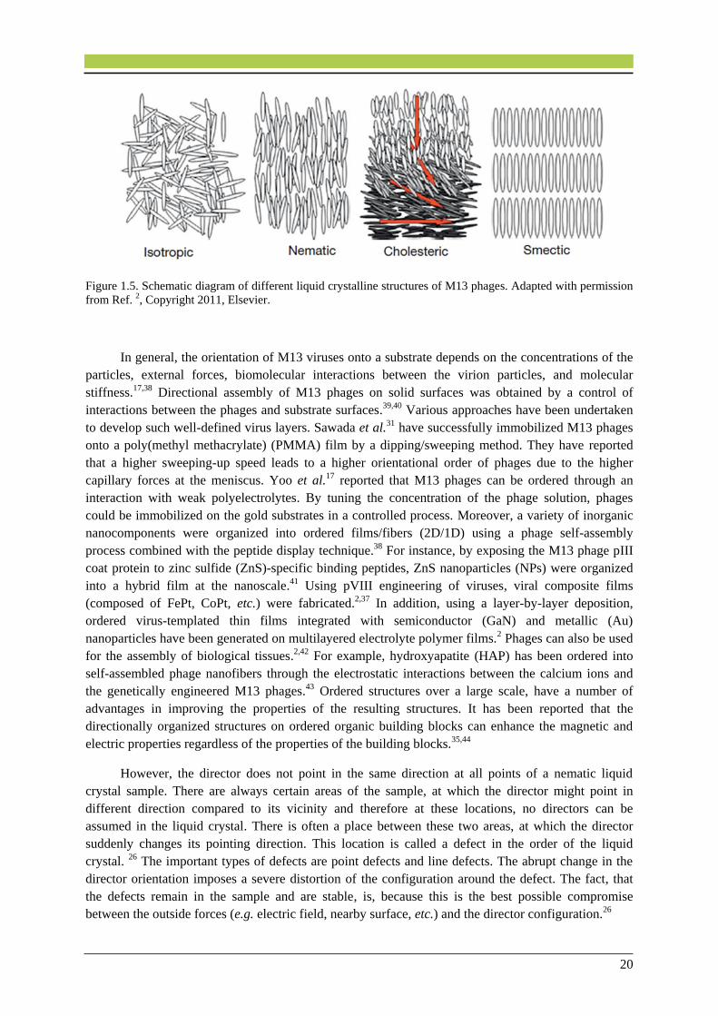
1.2.2. Textures and Defects in Liquid Crystals
Many filamentous viruses have been extensively studied as lyotropic liquid crystalline model
systems due to their monodispersity and long rod shape.15,30,31 The variables such as concentration and
external fields (e.g. electric and magnetic fields) have critical effect on their ordered liquid crystalline
structures.31,32,33 At low concentrations (< 5 mg/ml), phages are ordered randomly in an isotropic
liquid crystalline phase (isotropic). With increasing concentration (ranging from 10–20 mg/ml), the
ratio between the viral length to the distance between neighboring viral particles will become larger.
The virus particles start to align themselves into orientationally ordered configurations (nematic
phase).34 Going beyond the nematic concentration range (i.e. ~5-20 mg/ml), and with increasing the
concentration in the range between 20 and 80 mg/ml, phages start to intertwine with each other and
thus generating distinguishable periodic structures (helicity of the particles), which show finger print
structures in the polarized light micrographs (chiral nematic or cholesteric phase).34,35 Above 100
mg/ml, the viral particles attain positional order in addition to the orientational order along a direction
(smectic phase).32 These liquid crystalline phases are shown in Figure 1.5. The aforementioned
structures are all being considered in 3D bulk samples. However, some viruses such as M13 and fd
phages have been also used at high concentration ranges to grow two-dimensional ordered viral
films.36,37
20
Figure 1.5. Schematic diagram of different liquid crystalline structures of M13 phages. Adapted with permission
from Ref. 2, Copyright 2011, Elsevier.
In general, the orientation of M13 viruses onto a substrate depends on the concentrations of the
particles, external forces, biomolecular interactions between the virion particles, and molecular
stiffness.17,38 Directional assembly of M13 phages on solid surfaces was obtained by a control of
interactions between the phages and substrate surfaces.39,40 Various approaches have been undertaken
to develop such well-defined virus layers. Sawada et al.31 have successfully immobilized M13 phages
onto a poly(methyl methacrylate) (PMMA) film by a dipping/sweeping method. They have reported
that a higher sweeping-up speed leads to a higher orientational order of phages due to the higher
capillary forces at the meniscus. Yoo et al.17 reported that M13 phages can be ordered through an
interaction with weak polyelectrolytes. By tuning the concentration of the phage solution, phages
could be immobilized on the gold substrates in a controlled process. Moreover, a variety of inorganic
nanocomponents were organized into ordered films/fibers (2D/1D) using a phage self-assembly
process combined with the peptide display technique.38 For instance, by exposing the M13 phage pIII
coat protein to zinc sulfide (ZnS)-specific binding peptides, ZnS nanoparticles (NPs) were organized
into a hybrid film at the nanoscale.41 Using pVIII engineering of viruses, viral composite films
(composed of FePt, CoPt, etc.) were fabricated.2,37 In addition, using a layer-by-layer deposition,
ordered virus-templated thin films integrated with semiconductor (GaN) and metallic (Au)
nanoparticles have been generated on multilayered electrolyte polymer films.2 Phages can also be used
for the assembly of biological tissues.2,42 For example, hydroxyapatite (HAP) has been ordered into
self-assembled phage nanofibers through the electrostatic interactions between the calcium ions and
the genetically engineered M13 phages.43 Ordered structures over a large scale, have a number of
advantages in improving the properties of the resulting structures. It has been reported that the
directionally organized structures on ordered organic building blocks can enhance the magnetic and
electric properties regardless of the properties of the building blocks.35,44
However, the director does not point in the same direction at all points of a nematic liquid
crystal sample. There are always certain areas of the sample, at which the director might point in
different direction compared to its vicinity and therefore at these locations, no directors can be
assumed in the liquid crystal. There is often a place between these two areas, at which the director
suddenly changes its pointing direction. This location is called a defect in the order of the liquid
crystal. 26 The important types of defects are point defects and line defects. The abrupt change in the
director orientation imposes a severe distortion of the configuration around the defect. The fact, that
the defects remain in the sample and are stable, is, because this is the best possible compromise
between the outside forces (e.g. electric field, nearby surface, etc.) and the director configuration.26

21
Point defects are less common than line defects. As an example, point defects might appear in
a thin capillary tube in which the molecules must orient themselves perpendicular to the cylindrical
surface of the tube. A diagram of a capillary tube is shown in Figure 1.6 where two point defects with
the strength 𝑆 = −1 and 𝑆 = 1 are depicted. This means that the two point defects with the same
strength but different signs can combine and cancel each other. This is similar to, when two opposite
electric charges cancel each other.26
Figure 1.6. Point defects 𝑺 = −𝟏 and 𝑺 = 𝟏 in a capillary tube. Reprinted with permission from Ref. 45,
Copyright 2006, Taylor & Francis.
There are also possible line defects which might be present along the center of the capillary
tube. These line defects are called disclinations implying that the line represents a discontinuity in the
inclinations of the director. Four examples of many different disclinations are shown in Figure 1.7, in
which the direction of the disclinations lines is perpendicular to the page plane. One important feature
of these defects is that all disclinations with integer strength, whether positive or negative, are not
stable and can always relax.
Figure 1.7. (a)-(d) Schematic illustration of four different types of disclinations. The numbers imply the strength
of the disclinations.26
Defects in cholesteric and smectic liquid crystals are different from those occurring in nematics
due to their twisted or layered structure. These liquid crystals phases can deform in many ways, but
the most complicated situation is one that changes the pitch (i.e. the distance it takes for the molecules
to undergo a full 360° twist) of the phases which occur in fact very rarely.
22
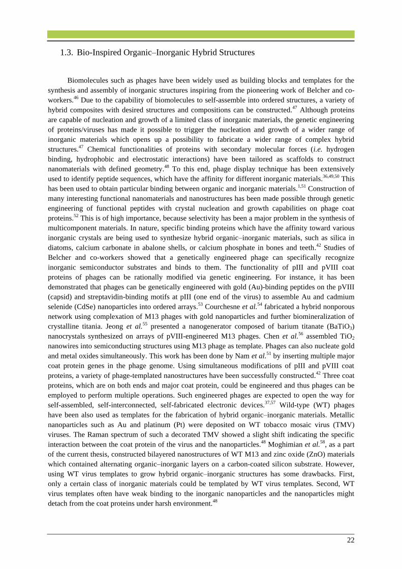
1.3. Bio-Inspired Organic–Inorganic Hybrid Structures
Biomolecules such as phages have been widely used as building blocks and templates for the
synthesis and assembly of inorganic structures inspiring from the pioneering work of Belcher and co-
workers.46 Due to the capability of biomolecules to self-assemble into ordered structures, a variety of
hybrid composites with desired structures and compositions can be constructed.47 Although proteins
are capable of nucleation and growth of a limited class of inorganic materials, the genetic engineering
of proteins/viruses has made it possible to trigger the nucleation and growth of a wider range of
inorganic materials which opens up a possibility to fabricate a wider range of complex hybrid
structures.47 Chemical functionalities of proteins with secondary molecular forces (i.e. hydrogen
binding, hydrophobic and electrostatic interactions) have been tailored as scaffolds to construct
nanomaterials with defined geometry.48 To this end, phage display technique has been extensively
used to identify peptide sequences, which have the affinity for different inorganic materials.36,49,50 This
has been used to obtain particular binding between organic and inorganic materials.1,51 Construction of
many interesting functional nanomaterials and nanostructures has been made possible through genetic
engineering of functional peptides with crystal nucleation and growth capabilities on phage coat
proteins.52 This is of high importance, because selectivity has been a major problem in the synthesis of
multicomponent materials. In nature, specific binding proteins which have the affinity toward various
inorganic crystals are being used to synthesize hybrid organic–inorganic materials, such as silica in
diatoms, calcium carbonate in abalone shells, or calcium phosphate in bones and teeth.42 Studies of
Belcher and co-workers showed that a genetically engineered phage can specifically recognize
inorganic semiconductor substrates and binds to them. The functionality of pIII and pVIII coat
proteins of phages can be rationally modified via genetic engineering. For instance, it has been
demonstrated that phages can be genetically engineered with gold (Au)-binding peptides on the pVIII
(capsid) and streptavidin-binding motifs at pIII (one end of the virus) to assemble Au and cadmium
selenide (CdSe) nanoparticles into ordered arrays.53 Courchesne et al.54 fabricated a hybrid nonporous
network using complexation of M13 phages with gold nanoparticles and further biomineralization of
crystalline titania. Jeong et al.55 presented a nanogenerator composed of barium titanate (BaTiO3)
nanocrystals synthesized on arrays of pVIII-engineered M13 phages. Chen et al.56 assembled TiO2
nanowires into semiconducting structures using M13 phage as template. Phages can also nucleate gold
and metal oxides simultaneously. This work has been done by Nam et al.51 by inserting multiple major
coat protein genes in the phage genome. Using simultaneous modifications of pIII and pVIII coat
proteins, a variety of phage-templated nanostructures have been successfully constructed.42 Three coat
proteins, which are on both ends and major coat protein, could be engineered and thus phages can be
employed to perform multiple operations. Such engineered phages are expected to open the way for
self-assembled, self-interconnected, self-fabricated electronic devices.37,57 Wild-type (WT) phages
have been also used as templates for the fabrication of hybrid organic–inorganic materials. Metallic
nanoparticles such as Au and platinum (Pt) were deposited on WT tobacco mosaic virus (TMV)
viruses. The Raman spectrum of such a decorated TMV showed a slight shift indicating the specific
interaction between the coat protein of the virus and the nanoparticles.48 Moghimian et al.58, as a part
of the current thesis, constructed bilayered nanostructures of WT M13 and zinc oxide (ZnO) materials
which contained alternating organic–inorganic layers on a carbon-coated silicon substrate. However,
using WT virus templates to grow hybrid organic–inorganic structures has some drawbacks. First,
only a certain class of inorganic materials could be templated by WT virus templates. Second, WT
virus templates often have weak binding to the inorganic nanoparticles and the nanoparticles might
detach from the coat proteins under harsh environment.48
23
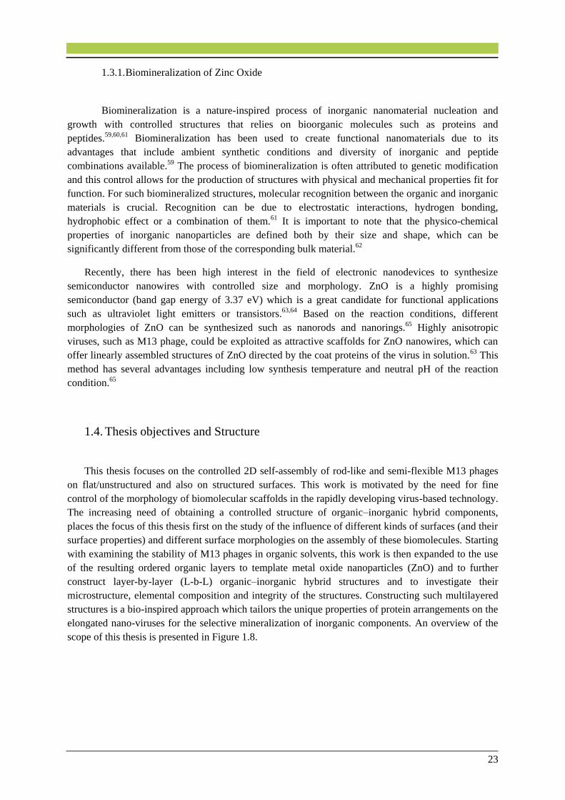
1.3.1. Biomineralization of Zinc Oxide
Biomineralization is a nature-inspired process of inorganic nanomaterial nucleation and
growth with controlled structures that relies on bioorganic molecules such as proteins and
peptides.59,60,61 Biomineralization has been used to create functional nanomaterials due to its
advantages that include ambient synthetic conditions and diversity of inorganic and peptide
combinations available.59 The process of biomineralization is often attributed to genetic modification
and this control allows for the production of structures with physical and mechanical properties fit for
function. For such biomineralized structures, molecular recognition between the organic and inorganic
materials is crucial. Recognition can be due to electrostatic interactions, hydrogen bonding,
hydrophobic effect or a combination of them.61 It is important to note that the physico-chemical
properties of inorganic nanoparticles are defined both by their size and shape, which can be
significantly different from those of the corresponding bulk material.62
Recently, there has been high interest in the field of electronic nanodevices to synthesize
semiconductor nanowires with controlled size and morphology. ZnO is a highly promising
semiconductor (band gap energy of 3.37 eV) which is a great candidate for functional applications
such as ultraviolet light emitters or transistors.63,64 Based on the reaction conditions, different
morphologies of ZnO can be synthesized such as nanorods and nanorings.65 Highly anisotropic
viruses, such as M13 phage, could be exploited as attractive scaffolds for ZnO nanowires, which can
offer linearly assembled structures of ZnO directed by the coat proteins of the virus in solution.63
This
method has several advantages including low synthesis temperature and neutral pH of the reaction
condition.65
1.4. Thesis objectives and Structure
This thesis focuses on the controlled 2D self-assembly of rod-like and semi-flexible M13 phages
on flat/unstructured and also on structured surfaces. This work is motivated by the need for fine
control of the morphology of biomolecular scaffolds in the rapidly developing virus-based technology.
The increasing need of obtaining a controlled structure of organic–inorganic hybrid components,
places the focus of this thesis first on the study of the influence of different kinds of surfaces (and their
surface properties) and different surface morphologies on the assembly of these biomolecules. Starting
with examining the stability of M13 phages in organic solvents, this work is then expanded to the use
of the resulting ordered organic layers to template metal oxide nanoparticles (ZnO) and to further
construct layer-by-layer (L-b-L) organic–inorganic hybrid structures and to investigate their
microstructure, elemental composition and integrity of the structures. Constructing such multilayered
structures is a bio-inspired approach which tailors the unique properties of protein arrangements on the
elongated nano-viruses for the selective mineralization of inorganic components. An overview of the
scope of this thesis is presented in Figure 1.8.
24
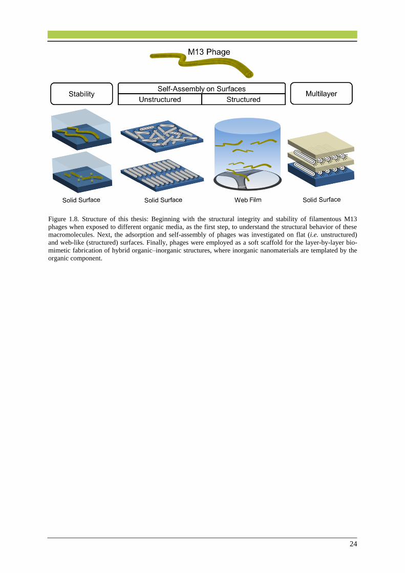
Figure 1.8. Structure of this thesis: Beginning with the structural integrity and stability of filamentous M13
phages when exposed to different organic media, as the first step, to understand the structural behavior of these
macromolecules. Next, the adsorption and self-assembly of phages was investigated on flat (i.e. unstructured)
and web-like (structured) surfaces. Finally, phages were employed as a soft scaffold for the layer-by-layer bio-
mimetic fabrication of hybrid organic–inorganic structures, where inorganic nanomaterials are templated by the
organic component.

25
2. Chapter 2. Characterization and
Experimental Techniques
In this thesis, the following electron and atomic force microscopes were used to perform transmission
electron microscopy (TEM), scanning electron microscopy (SEM) and atomic force microscopy
(AFM).
The conventional Zeiss 912 Omega 120 kV TEM with a LaB6 gun equipped with an Omega (Ω) in-
column energy filter and a Noran energy-dispersive X-ray spectroscopy (EDX) system.
The Zeiss Sub-Electron-Volt-Sub-Angstrom-Microscope (SESAM), a high-resolution 200-kV field-
emission gun (FEG) TEM microscope equipped with an electrostatic Ω-type monochromator, the in-
column MANDOLINE filter, and an EDX system (EDAX, Mahwah, NJ, USA).
The JEOL ARM200F (JEOL Co. Ltd) atomic-resolution TEM equipped with a cold FEG, a DCOR
probe Cs-corrector (CEOS Co. Ltd.), a 100 mm2 JEOL Centurio SDD-EDX detector, the Thermo
Noran System 7 EDX system (Thermo Fisher Scientific Inc.) and a Gatan GIF Quantum energy filter.
The system is set up for operation at voltages of 30, 60, 80 and 200 kV.
The Zeiss DSM 982 Gemini, a FEG SEM equipped with an secondary-electron (SE) in-lens detector
and an EDX detector (Thermo Noran Voyager 3105A) enabling imaging (secondary electrons and
backscattered electrons) and elemental analysis. The accelerating voltage is adjustable from 0.2 to 30
kV.
A Nanoscope III Multimode instrument AFM (Digital Instruments, Inc., Santa Barbara, CA, USA)
equipped with a silicon tip operating in tapping mode in air. AFM images were analyzed using the
WsXM software.
A Krüss G10 contact angle goniometer (Krüss GmbH, Germany) was used to measure the contact
angles and to investigate the hydrophobicity of solid substrates.
All the instruments and characterization techniques are discussed in more detail in the current chapter.
26
2.1. Scanning Electron Microscopy
The invention of scanning electron microscope (SEM) was soon after the transmission electron
microscope but took longer time to be developed for scientific research.66 Only after substitution of
magnetic lenses for electrostatic ones and after addition of stigmators to the lens column, the spatial
resolution of the instrument improved. Today, the number of existing scanning electron microscopes is
more than of transmission electron microscopes and are used in many fields, including medical and
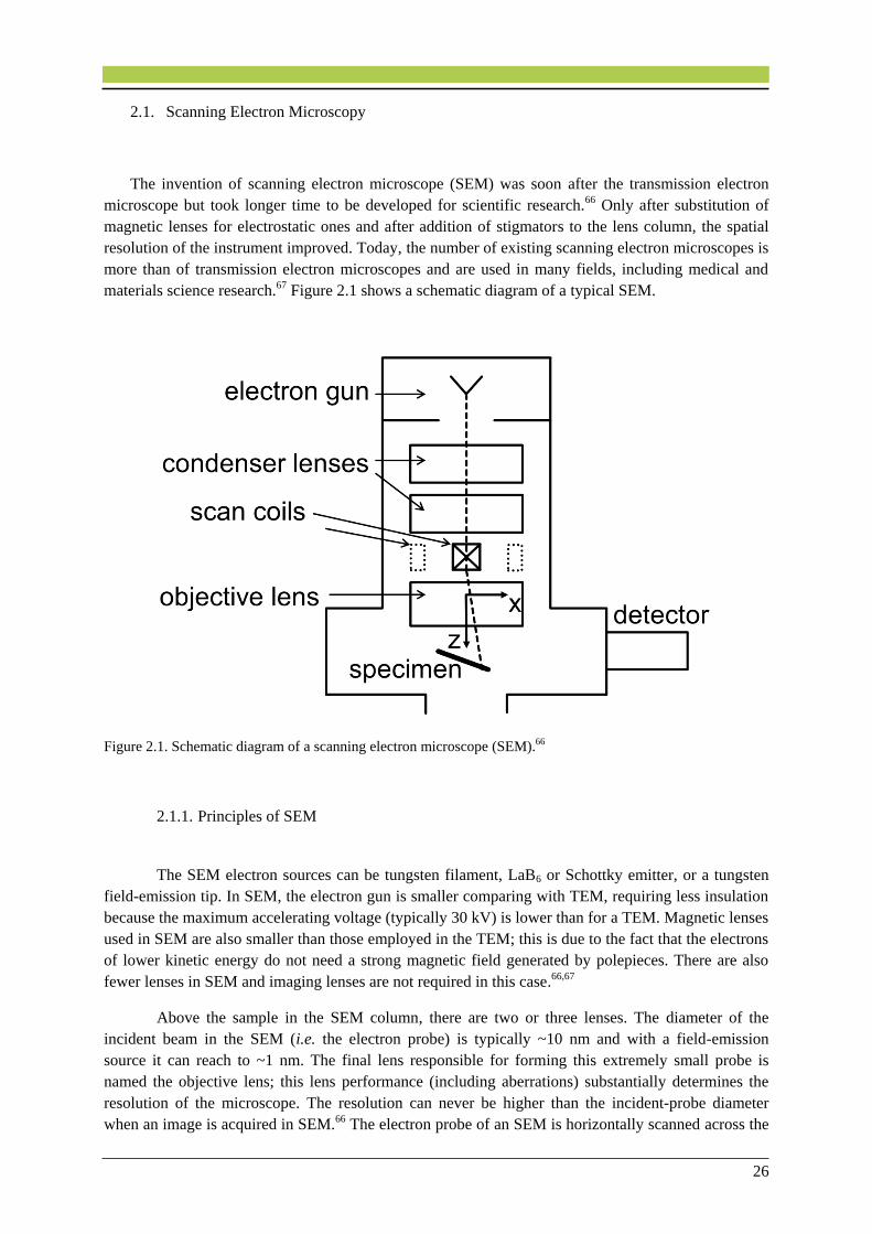
materials science research.67 Figure 2.1 shows a schematic diagram of a typical SEM.
Figure 2.1. Schematic diagram of a scanning electron microscope (SEM).66
2.1.1. Principles of SEM
The SEM electron sources can be tungsten filament, LaB6 or Schottky emitter, or a tungsten
field-emission tip. In SEM, the electron gun is smaller comparing with TEM, requiring less insulation
because the maximum accelerating voltage (typically 30 kV) is lower than for a TEM. Magnetic lenses
used in SEM are also smaller than those employed in the TEM; this is due to the fact that the electrons
of lower kinetic energy do not need a strong magnetic field generated by polepieces. There are also
fewer lenses in SEM and imaging lenses are not required in this case.66,67
Above the sample in the SEM column, there are two or three lenses. The diameter of the
incident beam in the SEM (i.e. the electron probe) is typically ~10 nm and with a field-emission
source it can reach to ~1 nm. The final lens responsible for forming this extremely small probe is
named the objective lens; this lens performance (including aberrations) substantially determines the
resolution of the microscope. The resolution can never be higher than the incident-probe diameter
when an image is acquired in SEM.66 The electron probe of an SEM is horizontally scanned across the

27
specimen in x and y directions (i.e. raster probe). The x-scan is relatively fast. However, the coils
above the objective lens create a magnetic field in the y-direction, applying a force on an electron
(moving in the z-direction) that deflects it in the x-direction (see Figure 2.1.). Therefore, the y-scan is
much slower than the x-scan. The whole procedure is sometimes referred to as raster scanning due to
the rectangular covered area of the specimen by the electron beam.66
2.1.2. Interaction of Electrons with a Solid
When accelerated electrons penetrate a solid bulk, they get scattered both by electrostatic
interaction with atomic nuclei (i.e. elastic scattering) and by interaction with electrons (i.e. inelastic
scattering). Most of the inelastic scattering is followed by electron deflection angles of less than 90°
that is called “forward” scattering. But a small fraction of the primary electrons are elastically
backscattered by deflection angles of 𝜃 > 90° which lose only a small fraction of their energy.
Because of their high kinetic energy, the backscattered electrons have a high chance of leaving the
specimen and entering the surrounding vacuum and then they can be further collected and contribute
to the backscattered electron (BSE) signal. Inelastic scattering consists of small scattering angles and
therefore contributes mostly to the image noise and little to the backscattered signal. However, until
the primary electrons are brought to rest and absorbed into the solid, their kinetic energy will be
reduced. The depth below the sample surface at which penetration occurs is called the penetration
depth or the electron range. The volume of sample at which the scattering of electrons occurs is called
the interaction volume and is represented as pear-shaped in cross section (see Figure 2.2).66 The
interaction volume when electrons hit a material with a higher atomic number Z is smaller, because the
probability of high-angle elastic scattering is proportional to Z2. In the case of a BSE image, the BSE
signal is collected from the BSE electrons which have enough energy to escape the solid depth of
about half of the penetration depth. Therefore, BSE images show a contrast indicating different
chemical composition of the specimen. It is noteworthy that the interaction volume and the penetration
depth are quantities that are averaged for a large number of electrons. The reason is that the behavior
of a single electron can be dramatically different from that of other electrons.66
Figure 2.2. Interaction volume dependency on the atomic number Z and incident energy of electrons.66

28
There are several interactions between the beam electrons and specimen atoms. Figure 2.3
illustrates the possible signals generated when a high energy electron beam interacts with a thin
specimen.
Figure 2.3. Different generated signals when an electron beam interacts with a thin specimen.68
2.1.3. Secondary-Electron Images
When inelastic scattering occurs, based on the principle of conservation of energy, any energy
lost by a primary electron will appear as a gain in energy of the atomic electrons that made the
inelastic scattering happen. If these are the valence or conduction electrons, they are weakly bound to
an atomic nucleus and only a small part of this acquired energy will be used up as potential energy, to
release them from a particular atom. The remaining energy will be retained as kinetic energy, allowing
the electrons to move through the solid as secondary electrons (SE or secondaries). The secondaries
themselves are charged particles and therefore can interact with other atomic electrons and be further
inelastically scattered and lose their kinetic energy. In fact, the energy of most secondary electrons is
less than 100 eV and, due to the inversely dependence of probability of inelastic scattering on kinetic
energy, the average distance that a secondary electron travels in the solid is just one or two nanometer.
As a result, most secondary electrons lose their kinetic energy within the interaction volume, and
consequently have no chance to escape the solid. But those secondaries which have been generated
close to the surface might escape into the vacuum. Typically, the secondary electrons which escape
from the solid are generated only less than about 2 nm below the surface (see Figure 2.4). The signal
of the SE image is collected only from this small depth that is called the escape depth. The SE image
is a property of the surface structure (the image displays topographical contrast), because the SE signal
used in the SEM is collected from the escaping secondary electrons in the vacuum. It is interesting to
mention that the average number of escaping secondaries per primary electron is 0.1 to 10 and it is
called the secondary-electron yield (SE yield, 𝛿). The 𝛿 value depends on the and also on the primary
electron energy 𝐸0 and also on the chemical composition of the surface of the solid. The value δ
decreases with increasing 𝐸0, because higher-energy primary electrons undergo less inelastic
scattering and thus within the escape depth there will be fewer secondary electrons.66,69
29
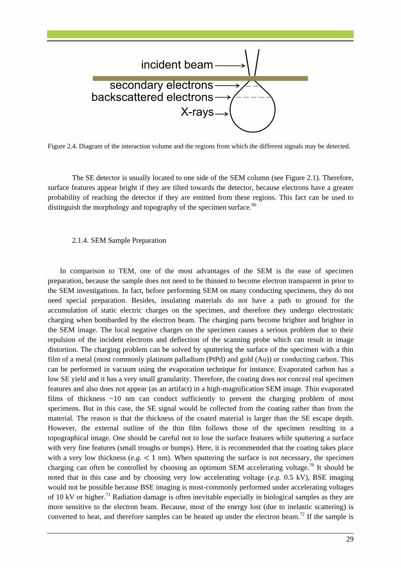
Figure 2.4. Diagram of the interaction volume and the regions from which the different signals may be detected.
The SE detector is usually located to one side of the SEM column (see Figure 2.1). Therefore,
surface features appear bright if they are tilted towards the detector, because electrons have a greater
probability of reaching the detector if they are emitted from these regions. This fact can be used to
distinguish the morphology and topography of the specimen surface.66
2.1.4. SEM Sample Preparation
In comparison to TEM, one of the most advantages of the SEM is the ease of specimen
preparation, because the sample does not need to be thinned to become electron transparent in prior to
the SEM investigations. In fact, before performing SEM on many conducting specimens, they do not
need special preparation. Besides, insulating materials do not have a path to ground for the
accumulation of static electric charges on the specimen, and therefore they undergo electrostatic
charging when bombarded by the electron beam. The charging parts become brighter and brighter in
the SEM image. The local negative charges on the specimen causes a serious problem due to their
repulsion of the incident electrons and deflection of the scanning probe which can result in image
distortion. The charging problem can be solved by sputtering the surface of the specimen with a thin
film of a metal (most commonly platinum palladium (PtPd) and gold (Au)) or conducting carbon. This
can be performed in vacuum using the evaporation technique for instance. Evaporated carbon has a
low SE yield and it has a very small granularity. Therefore, the coating does not conceal real specimen
features and also does not appear (as an artifact) in a high-magnification SEM image. Thin evaporated
films of thickness ~10 nm can conduct sufficiently to prevent the charging problem of most
specimens. But in this case, the SE signal would be collected from the coating rather than from the
material. The reason is that the thickness of the coated material is larger than the SE escape depth.
However, the external outline of the thin film follows those of the specimen resulting in a
topographical image. One should be careful not to lose the surface features while sputtering a surface
with very fine features (small troughs or bumps). Here, it is recommended that the coating takes place
with a very low thickness (e.g. < 1 nm). When sputtering the surface is not necessary, the specimen
charging can often be controlled by choosing an optimum SEM accelerating voltage.70 It should be
noted that in this case and by choosing very low accelerating voltage (e.g. 0.5 kV), BSE imaging
would not be possible because BSE imaging is most-commonly performed under accelerating voltages
of 10 kV or higher.71 Radiation damage is often inevitable especially in biological samples as they are
more sensitive to the electron beam. Because, most of the energy lost (due to inelastic scattering) is
converted to heat, and therefore samples can be heated up under the electron beam.72 If the sample is
30
composed of biological matter, the electron excitation of organic molecules can lead to bond rupture
so the organic material can undergo mass loss and decomposition after the electron exposure (i.e.
radiolysis). However, the damage is higher when the illumination area gets smaller, and that can limit
high-resolution studies of biological samples.66,67,69
2.2. Transmission Electron Microscopy
Transmission electron microscope (TEM) has the ability to display magnified images of a thin
specimen, typically with a magnification ranging from 103 to 106. Besides, the TEM can be used to
acquire electron-diffraction patterns (DPs), in order to analyze the properties of a crystalline specimen
or its crystallinity or to perform analytics. This overall property is obtained with an electron-optical
system containing an electron gun (in order to produce the beam of electrons) and several magnetic
lenses, assembled vertically to form an electron column.66,68 In transmission electron microscopy, a
specimen is required that is thin enough to be electron transparent, which allows for the transmission
of required number of electrons through the specimen to produce sufficient intensity in the TEM
analysis. When the electron beam interacts with the sample, a projection image is obtained.
2.2.1. Principles of TEM
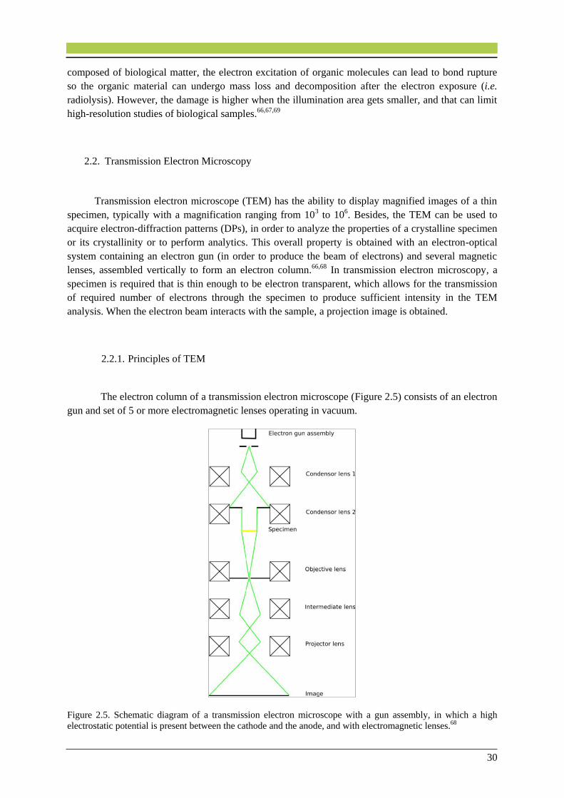
The electron column of a transmission electron microscope (Figure 2.5) consists of an electron
gun and set of 5 or more electromagnetic lenses operating in vacuum.
Figure 2.5. Schematic diagram of a transmission electron microscope with a gun assembly, in which a high
electrostatic potential is present between the cathode and the anode, and with electromagnetic lenses.68
31
The instrument consists of different sections. The illumination system includes the electron
gun, along with two or more condenser lenses that focus the electron beam onto the thin specimen.
The diameter of the beam and the intensity in the final TEM image are determined with the
illumination system design and operation, because the electron beam passes through a set of condenser
lenses focusing the beam of electrons with a desired diameter. The next section consists of the
objective lens and the specimen stage at which all of the beam-specimen interactions occur. Here, two
fundamental TEM operations take place, that is, the formation of the different kinds of images and
diffraction patterns which are further magnified for viewing and recording. The imaging system
produces a magnified image or a diffraction pattern of the specimen on a fluorescent screen or on a
monitor screen of a camera system. The operation of this imaging system determines the
magnification of the TEM image, while the spatial resolution that can be obtained from the
microscope, is largely influenced by the design of the imaging lenses.66,67
Electron Guns
There are two kinds of electron guns in the TEM, which are known as thermionic gun and
field-emission gun (FEG). Thermionic guns produce electrons when their filaments are heated. They
were formerly made of tungsten filaments, but nowadays lanthanum hexaboride (LaB6) is also used.
The materials, which have a high melting point with a lower potential function, are the ones preferred
for the filament. The sharp tip of the tungsten filament in the thermionic gun is heated up electrically.
When a high temperature is reached on the tungsten filament, it allows some of the electrons to gain
enough energy to overcome the work function of the tungsten-vacuum interface. Thereafter, the
electrons are emitted from the filament.68 In this way, the temperature of the tungsten filament
contributes to the emission of more electrons, but it also causes evaporation of the tungsten filament.
Due to this reason, there exists always a limit in maximum operation temperature. In a field-emission
gun, the electrons are generated using a high electric potential between the gun and an anode. In order
to produce electrons, a sharp tip usually tungsten is used as a cathode because higher electric fields are
generated at the sharper tips. Hence, if a very high electric field is generated on the metal surface, the
probability of an electron leaving the surface is higher. By this way, more electrons are emitted from a
tungsten filament than in that of thermionic gun. In the case that the tip works at ambient temperature
or at high temperatures (thermal-energy assisted), the electron gun is called cold FEG and thermal
FEG, respectively. Schottky emitters are thermal FEGs in which the tungsten tip is coated with a layer
of zirconium oxide for better conductivity at higher temperatures.68
Electromagnetic Lenses
The lenses are the prominent components in the transmission electron microscope, which
enables the use of the electron beam in order to form images in the TEM or to focus the beam into a
spot. Electron lenses are placed beyond the electron gun. The function of the lenses is to transform a
point in an object to a point in an image and to focus parallel rays to a point in the focal plane of the
lens. Electrons can be focused by two means; electrostatic or magnetic field. In an electromagnetic
lens there is a cylindrically symmetrical core of soft magnetic material such as soft iron (polepiece),
with a hole drilled through it (the bore of the polepiece). The second part of the lens is a coil of copper
wire which surrounds the polepiece. When we pass a current through the coil, a magnetic field is
created in the bore.68
The electron rays can be simply divided into two sections; electron rays that are close to the
optical axis, which form an image of the object with correct shape and position, and also the electron
rays, which are sided to the optical axis and do not come to focus at the correct position, causing a
32
blurred image called aberration. The aberrations can imperfect the lens operation and three major
aberrations are the spherical aberration, chromatic aberration and astigmatism. Together they influence
the lens performance and are responsible for the final image resolution obtained in the TEM. Spherical
aberration appears due to the trajectories of the electrons, which are far away from the optical axis, and
therefore get bent more heavily by the magnetic field than those close to the axis. This process leads to
an enlarged blurred image of a point in the image plane. In electron microscopy, the main goal is to
form a monochromatic electron beam (with a single wavelength). However, in practice, the power
supplies engender the electron energy variance. These variations are small and they do not cause
substantial problems in the microscopes. The energy fluctuations are usually due to the spread in the
energy of the electrons generated by the electron gun. In TEM, in addition to the power source which
causes the energy spread, the interaction of the electron beam with the specimen also lead to the
generation of electrons with different wavelengths. All of these cause a distortion in the final image in
the TEM called chromatic aberration. In TEM, the energy absorption in the specimen can produce a
significant change in primary electron energy, which will introduce substantial distortions in the
image. Deviance from rotational symmetry is typical for the electromagnetic lenses. This defect is
caused by the asymmetry in the windings and contaminated apertures. A circular asymmetrical lens
will cause electrons to divert from a point object to be focused at the image at two separate lines of
foci. This effect can be realized by the stretching of the image in two perpendicular lines when the
objective lens is underfocused and then overfocused, respectively. By using a stigmator, which is an
octuple of small electromagnetic coils generating a weak magnetic field to remunerate the lens
distortions, the astigmatism can be corrected.66
In TEM there are two or more condenser lenses which are positioned below the electron gun.
Condenser apertures are placed between the condenser lenses. The condenser system allows for the
control of the spot size and the beam convergence angle.73
The TEM specimen in a form of a thin foil, section, or fine particles transparent to the electron
beam is located beyond the objective lens. At the specimen surface, an image of the electron density
distribution is formed by the objective lens.66 A diffraction pattern is generated in the back focal plane
of the objective lens and then the combination of the diffracted beams forms an image in the image
plane of the objective lens. The projection and intermediate lenses below the objective lens are used to
focus and further magnify the image or the diffraction pattern onto the viewing screen. An ultimate
magnification is reachable by the use of these lenses each capable of a magnification of up to twenty
times. The first projector lens in the column is generally named as intermediate lens, which can switch
between the image mode and the diffraction mode. In diffraction mode, the intermediate lens is
focused on the back focal plane of the objective and the diffraction pattern is projected onto the
viewing screen.73 To attain quantitative information about the materials microstructure, the TEM can
be employed to generate several image types or diffraction patterns obtained from desired regions of
the specimen.68 An objective aperture is situated near the objective lens. The aperture limits and
controls the collection angle of the lens and therefore the angular spread of the electrons.
The fluorescent screen made of a disk coated with doped zinc-sulfide is placed at the bottom
of the electron column. It emits green light upon impingement of the electron beam onto the screen.
The intensity of the green light is directly proportional to the intensity of the electron beam.68 A
camera is mounted below the viewing screen to record the images which detects the incident electrons.
Nowadays, charge-coupled device (CCD) array cameras are widely used in electron microscopes, and
have become a standard for recording images and diffraction patterns in real time TV mode. CCDs are
devices made up from metal-insulator-silicon, being capable of storing the charges created by electron
beams or light.

33
Some microscopes can be equipped with energy filters, which substantially enhance the
quality of images and diffraction patterns, particularly in the case of thick specimens where the
frequency of occurrence of inelastic scattering is higher. The energy filter is positioned between the
intermediate and the projector lenses in the TEM column below the specimen. The energy filter
removes the inelastically scattered electrons and permits the scattered ones to travel down the
microscope column with specific amount of energy loss.68
Contrast Mechanisms
The most important mechanism, which takes part in the image contrast formation in the TEM,
is mass-thickness contrast. This contrast originates from incoherent elastic scattering of electrons. As
electrons penetrate the specimen they are scattered by elastic nuclear interaction. The atomic number
determines the cross section for elastic scattering. As the specimen thickness increases the elastic
scattering also increases since the mean-free path remains constant. Therefore, specimens consisting of
higher atomic number elements Z will scatter more electrons than those of having lower Z. Hence, the
image formed from thicker regions appears darker due to the less electrons transmitted from that
region. However, the image formed from the thinner area, appears brighter in the image plane due to
the less scattering occurred in that area. This will create differential intensity in an image.66 Mass-
thickness contrast is the main imaging mechanism in biological applications.68
Contrast in TEM images can be also due to the electron waves phase difference, which are
scattered through a specimen. Whereas bright- and dark-field TEM modes usually use only the direct
beam or a single diffracted beam, the phase contrast method uses the interference of two or more
beams. There is a small phase difference due to the scattering in the specimen while the electrons
leaving the bottom surface of a thin specimen. Phase contrast imaging is the basis for the so called
high-resolution TEM (HRTEM). Phase contrast contains important information of the material and
provides information of the periodically ordered part of the crystals.68
Energy Dispersive X-ray Analysis
Energy dispersive X-ray spectroscopy (EDX) is a qualitative and quantitative X-ray analytical
technique that allows for the identification of elements with atomic number 𝑍 > 3 as well as for
elemental ratio quantification. EDX is considered as a non-destructive analytical technique, that is, the
sample can be reanalyzed many times. However, very often materials can damage under the electron
beam. Using this method, a quick overview of the elements present in the solid specimen can be
obtained.74 An electron beam is focused on the sample and the electrons from the primary beam
penetrate the sample and interact with its atoms. The X-rays resulting from these interactions are
further detected by an energy dispersive detector which displays a spectrum of intensity (number of X-
rays) versus energy. The energies of the characteristic X-rays allow for the identification of the
elements of the sample, while the intensities of the characteristic X-ray peaks allows for the
quantification of the concentrations of the elements. However, to obtain the real concentrations,
certain corrections to the raw intensities are needed.73 The general approach for thin samples (i.e.
absorption or fluorescence within the sample can be neglected) in TEM is the Cliff-Lorimer method.
In this method, for a binary system (a substance composed of two elements 𝐴 and 𝐵), characteristic X-
ray intensities 𝐼𝐴 and 𝐼𝐵 are measured. Then, the concentration ratio of the two elements 𝐶𝐴/𝐶𝐵 is
obtained from the equation 𝐶𝐴/𝐶𝐵 = 𝑘𝐴𝐵 ∙ 𝐼𝐴/𝐼𝐵, where 𝑘 is termed the Cliff-Lorimer factor (or 𝑘-
factor) which is related only to the atomic-number for thin samples (the X-ray absorption and the
fluorescence are minimal). The Cliff-Lorimer factor can be different in each TEM/EDX system and it
depends also on the voltage being used. For ternary or higher order systems, the same equation applies

34
to each pair of elements (𝐴𝐵, 𝐵𝐶, etc.) keeping in mind that the assumed elements must constitute
100% of the specimen (𝐶𝐴 + 𝐶𝐵 + … + 𝐶𝑛 = 100%).68
2.2.2. Scanning TEM (STEM)
To form scanning TEM (STEM) images, a fine probe is used. The scanning beam must always
scan parallel to the optic axis. Here, two pairs of scan coils are used to achieve parallel incidence to
pivot the beam about the front-focal plane of the upper objective polepiece. It is important to note that
the quality of STEM images does depend on the probe which has aberrations due to the lens that was
used to form it. In STEM, we do not use lenses to form the image. Therefore, aberrations present in
the imaging lenses (i.e. chromatic aberration) have no influence on the image resolution.68
2.2.2.1. Bright-Field STEM Images
To form an image in STEM mode, we simply use the scan coils to scan the beam on the
specimen. Due to the serial recording, image formation in STEM mode takes longer time than in TEM
mode. In the TEM mode, we insert an aperture into the plane of the TEM diffraction pattern (i.e.
objective aperture) and then only the direct beam, and not the other scattered electrons, are allowed to
go through it into the imaging system. However, in STEM mode, instead of an aperture we use a
bright-field (BF) detector which intercepts with the direct-beam electrons. Therefore, we allow only
the electrons we want to hit the detector and contribute to the image formation. The signal is then
generated at a point on the specimen.68 This signal will be further amplified and it will be shown at an
equivalent point on the computer display (Figure 2.6).
Figure 2.6. A schematic of formation of a scanning image (a) The beam-scan on the specimen is controlled by
the scan coils in the microscope. (b) The scan coils control the beam-scan on the display screen of the STEM. (c)
STEM image formation: A BF detector is placed in the microscope to intercept the direct beam. An ADF
detector has a hole in the middle and is centered on the optical axis and surrounds the BF detector.68

35
2.2.2.2. Annular Dark-Field (ADF) STEM Images
For dark-field imaging, we usually use an annular detector, on which all the scattered
electrons fall. As shown in Figure 2.7, the ADF detector has a hole in the middle and is centered on
the optical axis, and therefore it is complementary to the BF image and collects low-angle elastically
scattered electrons. This process is called annular dark-field (ADF) imaging, which has several
advantages including less noise in the images, higher image contrast than the TEM dark-field (DF)
contrast, and imaging of elements with low atomic number.68
2.2.2.3. High-Angle Annular Dark-Field (HAADF) STEM Images
We can also use another detector which surrounds the ADF detector which can pick the
electrons which are scattered to higher angles forming a so-called high-angle (HA) ADF (or Z-
contrast) image (HAADF). In ADF there is a problem of the contribution of the inelastically scattered
electrons to the ADF signal. Since the normal ADF detectors collect Bragg-scattered electrons, it is
necessary to have a detector with a higher angle to avoid the Bragg-scattered electrons to hit the
detector. Thus, HAADF detectors are designed to collect scattered electrons through very high angles.
A schematic of the HAADF detector setup along with BF and ADF detectors in a STEM is shown in
Figure 2.7. HAADF images have the advantage of having its contrast unaffected by small specimen
thickness changes.68 The intensity of the HAADF signal is proportional to 𝑍1.7−2.0 where 𝑍 is the
atomic number of the sample.75
Figure 2.7. A schematic of the HAADF, ADF, and BF detector setup in STEM along with the range of electron
scattering angles collected by each detector.68
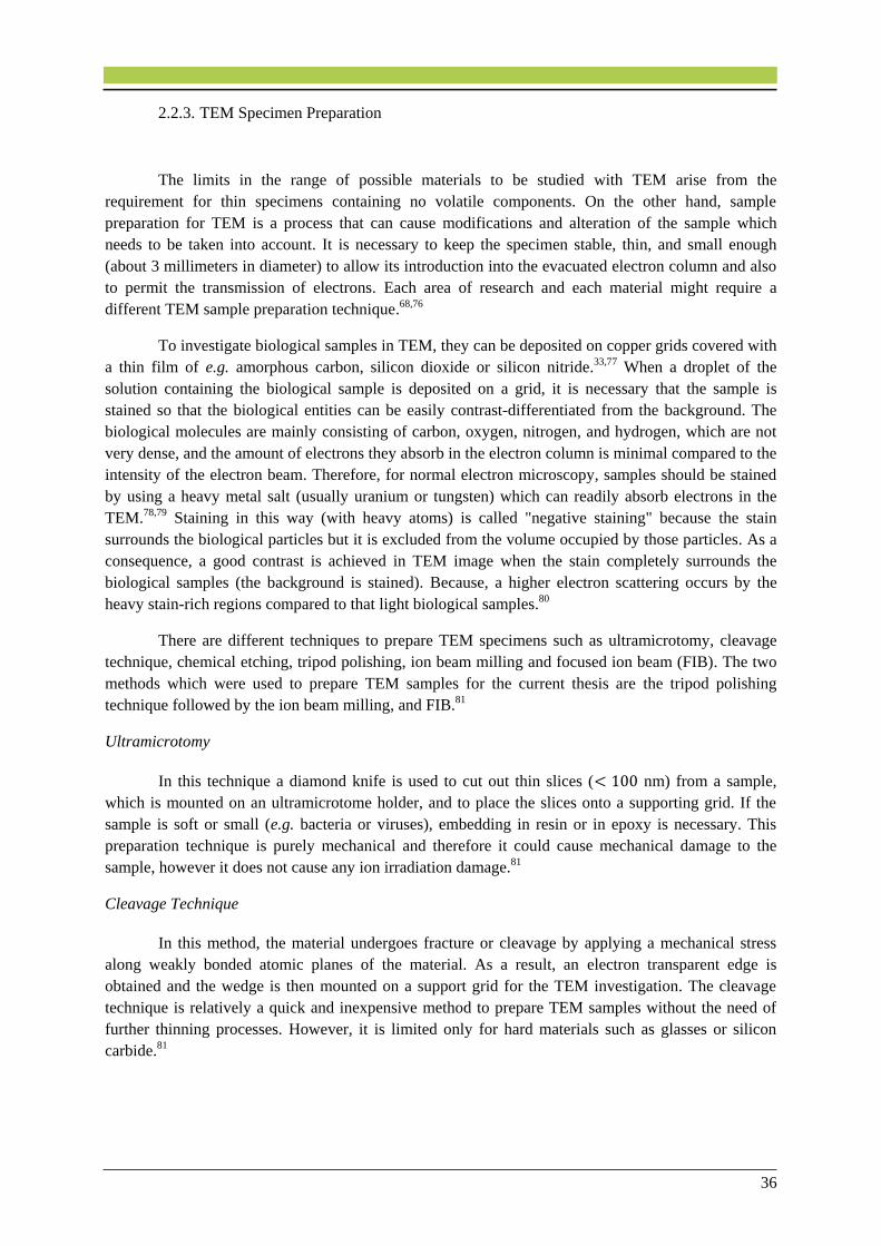
36
2.2.3. TEM Specimen Preparation
The limits in the range of possible materials to be studied with TEM arise from the
requirement for thin specimens containing no volatile components. On the other hand, sample
preparation for TEM is a process that can cause modifications and alteration of the sample which
needs to be taken into account. It is necessary to keep the specimen stable, thin, and small enough
(about 3 millimeters in diameter) to allow its introduction into the evacuated electron column and also
to permit the transmission of electrons. Each area of research and each material might require a
different TEM sample preparation technique.68,76
To investigate biological samples in TEM, they can be deposited on copper grids covered with
a thin film of e.g. amorphous carbon, silicon dioxide or silicon nitride.33,77 When a droplet of the
solution containing the biological sample is deposited on a grid, it is necessary that the sample is
stained so that the biological entities can be easily contrast-differentiated from the background. The
biological molecules are mainly consisting of carbon, oxygen, nitrogen, and hydrogen, which are not
very dense, and the amount of electrons they absorb in the electron column is minimal compared to the
intensity of the electron beam. Therefore, for normal electron microscopy, samples should be stained
by using a heavy metal salt (usually uranium or tungsten) which can readily absorb electrons in the
TEM.78,79 Staining in this way (with heavy atoms) is called "negative staining" because the stain
surrounds the biological particles but it is excluded from the volume occupied by those particles. As a
consequence, a good contrast is achieved in TEM image when the stain completely surrounds the
biological samples (the background is stained). Because, a higher electron scattering occurs by the
heavy stain-rich regions compared to that light biological samples.80
There are different techniques to prepare TEM specimens such as ultramicrotomy, cleavage
technique, chemical etching, tripod polishing, ion beam milling and focused ion beam (FIB). The two
methods which were used to prepare TEM samples for the current thesis are the tripod polishing
technique followed by the ion beam milling, and FIB.81
Ultramicrotomy
In this technique a diamond knife is used to cut out thin slices (< 100 nm) from a sample,
which is mounted on an ultramicrotome holder, and to place the slices onto a supporting grid. If the
sample is soft or small (e.g. bacteria or viruses), embedding in resin or in epoxy is necessary. This
preparation technique is purely mechanical and therefore it could cause mechanical damage to the
sample, however it does not cause any ion irradiation damage.81
Cleavage Technique
In this method, the material undergoes fracture or cleavage by applying a mechanical stress
along weakly bonded atomic planes of the material. As a result, an electron transparent edge is
obtained and the wedge is then mounted on a support grid for the TEM investigation. The cleavage
technique is relatively a quick and inexpensive method to prepare TEM samples without the need of
further thinning processes. However, it is limited only for hard materials such as glasses or silicon
carbide.81
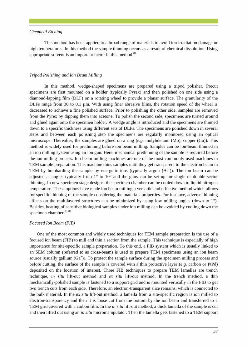
37
Chemical Etching
This method has been applied to a broad range of materials to avoid ion irradiation damage or
high temperatures. In this method the sample thinning occurs as a result of chemical dissolution. Using
appropriate solvent is an important factor in this method.81
Tripod Polishing and Ion Beam Milling
In this method, wedge-shaped specimens are prepared using a tripod polisher. Precut
specimens are first mounted on a holder (typically Pyrex) and then polished on one side using a
diamond-lapping film (DLF) on a rotating wheel to provide a planar surface. The granularity of the
DLFs range from 30 to 0.1 µm. With using finer abrasive films, the rotation speed of the wheel is
decreased to achieve a fine polished surface. Prior to polishing the other side, samples are removed
from the Pyrex by dipping them into acetone. To polish the second side, specimens are turned around
and glued again onto the specimen holder. A wedge angle is introduced and the specimens are thinned
down to a specific thickness using different sets of DLFs. The specimens are polished down in several
steps and between each polishing step the specimens are regularly monitored using an optical
microscope. Thereafter, the samples are glued on a ring (e.g. molybdenum (Mo), cupper (Cu)). This
method is widely used for prethinning before ion beam milling. Samples can be ion-beam thinned in
an ion milling system using an ion gun. Here, mechanical prethinning of the sample is required before
the ion milling process. Ion beam milling machines are one of the most commonly used machines in
TEM sample preparation. This machine thins samples until they get transparent to the electron beam in
TEM by bombarding the sample by energetic ions (typically argon (Ar+)). The ion beam can be
adjusted at angles typically from 1° to 10° and the guns can be set up for single or double-sector
thinning. In new specimen stage designs, the specimen chamber can be cooled down to liquid nitrogen
temperature. These options have made ion beam milling a versatile and effective method which allows
for specific thinning of the sample considering the materials properties. For instance, adverse thinning
effects on the multilayered structures can be minimized by using low milling angles (down to 1°).
Besides, heating of sensitive biological samples under ion milling can be avoided by cooling down the
specimen chamber.81,82
Focused Ion Beam (FIB)
One of the most common and widely used techniques for TEM sample preparation is the use of a
focused ion beam (FIB) to mill and thin a section from the sample. This technique is especially of high
importance for site-specific sample preparation. To this end, a FIB system which is usually linked to
an SEM column (referred to as cross-beam) is used to prepare TEM specimens using an ion beam
source (usually gallium (Ga+)). To protect the sample surface during the specimen milling process and
before cutting, the surface of the sample is covered with a thin protective layer (e.g. carbon or PtPd)
deposited on the location of interest. Three FIB techniques to prepare TEM lamellas are trench
technique, in situ lift-out method and ex situ lift-out method. In the trench method, a thin
mechanically-polished sample is fastened to a support grid and is mounted vertically in the FIB to get
two trench cuts from each side. Therefore, an electron-transparent slice remains, which is connected to
the bulk material. In the ex situ lift-out method, a lamella from a site-specific region is ion milled to
electron-transparency and then it is loose cut from the bottom by the ion beam and transferred to a
TEM grid covered with a carbon film. In the in situ lift-out method, a thick lamella of the sample is cut
and then lifted out using an in situ micromanipulator. Then the lamella gets fastened to a TEM support

38
grid using FIB metal deposition and it can be additionally thinned in the FIB. Lift-out methods are
significantly faster than the trench method because no mechanical thinning is required.81,82
2.3. Atomic Force Microscopy
Atomic force microscopy is a method to investigate topographical features of a conducting or
insulating sample by means of a vibrating tip, in which the force between the tip and sample is
measured. Most modern AFMs use a laser beam deflection system. A schematic of atomic force
microscope is shown in Figure 2.8.
Figure 2.8. Schematic illustration of an atomic force microscope.83
In Figure 2.9, a diagram of the force between the tip and sample is illustrated. Three different
regimes are shown in this diagram. First, if the tip is far away from the surface of the sample, there is
almost no force acting between tip and sample. Second, for closer distances an attractive (negative)
force between tip and sample appears. Lastly, for very small distances between the tip and the sample,
a strong electrostatic repulsive force occurs. One problem here is that the probe can penetrate the
sample, leading to elastic and further inelastic deformations. It should be noted that for one value of
the measured force in the attractive regime, there are two tip-sample distances, point 1 and point 2 on
the force distance diagram. The force between tip and sample can be measured using the deflection of
the cantilever. The cantilever acts like a spring and the tip-sample force is proportional to the
cantilever deflection. When the AFM tip is probing over the sample, a laser beam is reflected from the
back of a reflective cantilever attached to the tip. This reflected light interacts with a position sensitive
detector and delivers the frequency and the phase, the tip is vibrating at. The surface topography is
then mapped while scanning over the sample by changing the z-position of the tip in such a way that
the tip-sample force (correspondingly, the tip-sample distance) is kept constant. If the measurements
are performed in the repulsive regime of the force-distance curve, the operating mode is called contact
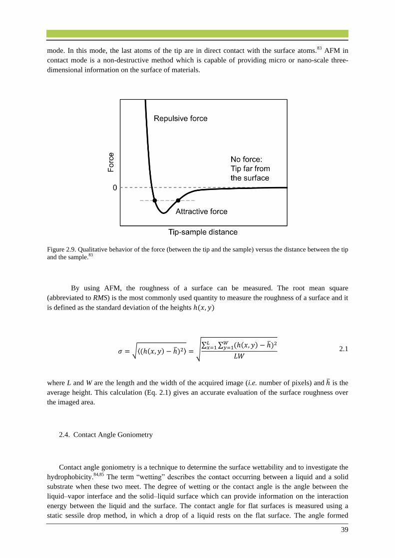
39
mode. In this mode, the last atoms of the tip are in direct contact with the surface atoms.83 AFM in
contact mode is a non-destructive method which is capable of providing micro or nano-scale three-
dimensional information on the surface of materials.
Figure 2.9. Qualitative behavior of the force (between the tip and the sample) versus the distance between the tip
and the sample.83
By using AFM, the roughness of a surface can be measured. The root mean square
(abbreviated to RMS) is the most commonly used quantity to measure the roughness of a surface and it
is defined as the standard deviation of the heights ℎ(𝑥, 𝑦)
𝜎 = √⟨(ℎ(𝑥, 𝑦) − ℎ)2⟩ = √∑ ∑ (ℎ(𝑥, 𝑦) − ℎ)2𝑊
𝑦=1𝐿𝑥=1
𝐿𝑊 2.1
where L and W are the length and the width of the acquired image (i.e. number of pixels) and ℎ is the
average height. This calculation (Eq. 2.1) gives an accurate evaluation of the surface roughness over
the imaged area.
2.4. Contact Angle Goniometry
Contact angle goniometry is a technique to determine the surface wettability and to investigate the
hydrophobicity.84,85 The term “wetting” describes the contact occurring between a liquid and a solid
substrate when these two meet. The degree of wetting or the contact angle is the angle between the
liquid–vapor interface and the solid–liquid surface which can provide information on the interaction
energy between the liquid and the surface. The contact angle for flat surfaces is measured using a
static sessile drop method, in which a drop of a liquid rests on the flat surface. The angle formed

40
between the liquid–solid and the liquid–vapor interface is then measured using an optical microscope.
As shown in Figure 2.10, if the liquid has a strong attraction towards the solid surface (that is a
hydrophilic surface), the liquid droplet will spread out on the surface and the contact angle will be low
(close to zero). Whereas hydrophobic surfaces have a contact angle close or greater than 90°.
Superhydrophobic surfaces are considered to have a contact angle greater than 150°.84
Figure 2.10. Schematic illustration of different contact angles and wettability of solid surfaces.84
2.5. Phage Propagation and Purification
M13KE (WT M13) phage was purchased from New England Biolabs, Inc. (Frankfurt, Germany).
Competent cells of E. coli ER2738 were transfected with the replicative form (RF) DNA of M13KE.
The transfected cells were shaken for 60 min at 37 . After propagation, several dilutions of the
transfected cells were made. 100 μl of the diluted cells were mixed with 300 μl of an overnight culture
of E. coli ER2738 cells in 3-ml melted Luria Bertani (LB) top agar (47 ) and plated on LB agar
plates with 40 µg/ml 5-bromo-4-chloro-3-indolyl β-D-galactopyranoside (X-gal) and 0.2 mM
isopropyl β-D-thiogalactopyranoside (IPTG). After solidification of the top agar, agar plates were
incubated at 37 °C overnight. To generate M13 phage, a single blue plaque was picked, and the phage
was eluted in 500 μl of TE buffer (10 mM Tris/HCl, pH 8.0, 1 mM ethylenediaminetetraacetic acid)
for 1 h. The obtained phage stock of M13KE was used for infection of a 400 ml culture of E. coli
ER2738 cells at a density of 1 × 10⁸ cells/ml. Adsorption of the phage was allowed for 15 min at
room temperature without shaking. Subsequently, for propagation of the phage, the infected cells were
grown at 37 in 2x yeast extract tryptone (2xYT)-medium overnight. The phage was harvested from
the supernatant after removing the cells by centrifugation and precipitating the phage out of solution
by adding 1/6 volume of 20% polyethylene glycol (PEG) 6000 and 2.5 M sodium chloride (NaCl).
After centrifugation at 12,000 × g (gravitational force) at 4 for 20 min the phage pellet was
suspended in 30 ml of Tris (hydroxymethyl)aminomethane (tris-buffered saline or TBS) (20 mM
Tris/HCl, pH 7.4, 150 mM NaCl, 2.7 mM KCl) and reprecipitated with 1/6 volume of 20% PEG
6000/2.5 M NaCl. The pellet was suspended in 1 to 5 ml of the TBS buffer.
The phage titer was determined by spectrophotometry. The method is based on the relationship
between the length of the viral DNA and the amount of the proteins, which, together, are the major
contributors of the absorption spectrum in the UV range at 269 nm. The relationship between virion
number and absorption was calculated by using the equation:86
𝑣𝑖𝑟𝑖𝑜𝑛𝑠/𝑚𝑙 = (𝐴269 − 𝐴320) × (6 × 1016)/𝑛𝑢𝑚𝑏𝑒𝑟 𝑜𝑓 𝑏𝑎𝑠𝑒𝑠 𝑝𝑒𝑟 𝑣𝑖𝑟𝑖𝑜𝑛 2.2

41
2.6. Convective Assembly Technique
Convective assembly (i.e. controlled drying) has been developed as an easily adopted and
inexpensive tool for the deposition of the nanoparticles in ordered structures on a solid surface. This
technique relies on the accumulation of particles near the three phase contact lines driven by solvent
evaporation (shown schematically in Figure 2.11). In plate-withdrawal experiments, a glass plate is
withdrawn with a constant speed with a trapped colloidal suspension to form ordered layers. The
suspension along with the particles is moved along the contact line, driven both by the glass plate
motion and the evaporative flux. The solvent evaporation leads to an increase of the concentration of
the elongated particles in the solution at the contact lines with the solid surface (to compensate for the
evaporated solvent) and causes the orientational ordering of the particles. When the meniscus
thickness near the contact line becomes less than the particle diameter, an attraction occurs from very
strong capillary interactions that lead to the formation of layers of particles.87
Figure 2.11. Schematic apparatus of convective nanoparticle assembly for controlled deposition. Reprinted by
permission from Ref. 35, copyright 2012, from the Chemical Society of Japan and Wiley-VCH, Weimheim.
I used the convective assembly technique to assemble filamentous M13 phages in ordered
structures on a solid surface. A convective assembly apparatus was designed and assembled in house
as a part of the present thesis (see Figure 2.11). The apparatus is made up of a controlled linear motor
(Pump 11, Harvard Apparatus, Holliston, MA, USA) and a glass slide with a 45° orientation with
regard to the substrate holder plane. A viral solution is applied on the edge of the glass slide to form a
thin strip of solution extended along the substrate. Viral particles are then directionally deposited by
pulling the meniscus containing the virus solution with a constant rate. It should be mentioned that the
angle between the glass slide and the substrate is believed to not have an influence on the assembly
process. Because, the contact angle of the substrate remains constant regardless of a change in the
glass-substrate subtending angle.

42
Figure 2.12. A Convective assembly apparatus designed and built up using a controlled linear motor (Pump 11,
Harvard Apparatus, Holliston, MA, USA) and a oriented glass slide (45° with regard to the substrate plane). This
apparatus was designed and assembled as a part of the current thesis. Photo Courtesy: Robin Lingstädt.
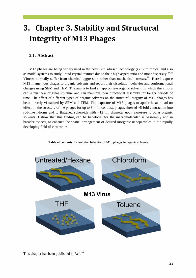
43
3. Chapter 3. Stability and Structural
Integrity of M13 Phages
3.1. Abstract
M13 phages are being widely used in the novel virus-based technology (i.e. virotronics) and also
as model systems to study liquid crystal textures due to their high aspect ratio and monodispersity.24,41
Viruses normally suffer from chemical aggression rather than mechanical stresses.88 Here I expose
M13 filamentous phages to organic solvents and report their dissolution behavior and conformational
changes using SEM and TEM. The aim is to find an appropriate organic solvent, in which the virions
can retain their original structure and can maintain their directional assembly for longer periods of
time. The effect of different types of organic solvents on the structural integrity of M13 phages has
been directly visualized by SEM and TEM. The exposure of M13 phages to apolar hexane had no
effect on the structure of the phages for up to 8 h. In contrast, phages showed ~8-fold contraction into
rod-like I-forms and to flattened spheroids with ~12 nm diameter upon exposure to polar organic
solvents. I show that this finding can be beneficial for the macromolecular self-assembly and in
broader aspects, to enhance the spatial arrangement of desired inorganic nanoparticles in the rapidly
developing field of virotronics.
Table of contents: Dissolution behavior of M13 phages in organic solvents
This chapter has been published in Ref. 89

44
3.2. Introduction
Several studies have been devoted to stress the key role of organic solvents on protein folding and
inactivation of viruses,90,91 yet it has been shown that different kinds of filamentous viruses, even from
the same class, show different structural integrity in an organic solvent.92 For instance, the filamentous
phage Pf1 was inactivated in diethyl ether and acetone, whereas the filamentous phage fd retained its
native structure in these solvents.93 M13 phages are among the phages being successfully used in
templating inorganic nanoparticles and hence in the development of optical biosensors and battery
devices.52,94,95 The major coat protein (pVIII) is comprised of 50 amino acid residues with a highly
hydrophobic core that accounts for the interlock of the coat protein with its subunits. 15,22 It has been
reported that these hydrophobic interactions have a strong role in the stabilization of virions against
denaturation.93
M13 filaments are highly sensitive to ultrasonication15 and their worm-like shape would change to
a mucus-like structure under near-infrared laser irradiations.96 The denaturation process in solutions
has been examined and observed in aqueous-organic mixtures. But viruses might experience a higher
degree of denaturation in pure organic solvents. Solvent properties such as hydrophobicity and
hydrogen-bonding capacity have a high impact on the structural integrity of proteins and virus
particles.24,90 It has been reported that M13 phages are very stable viral particles that can resist heating
and cooling processes between 90 °C and −20 °C and can resist high and low pH values without
losing their structural integrity.15,20,23,78 For many applications in virotronics, viruses must be stable for a
certain period of time under a wide range of conditions – in particular, in different organic solvents.
These solvents are often used in the production of organic electronic devices that are fabricated by
solution processing (e.g. organic light-emitting diodes).97 While a number of studies have been
devoted to the structural stability of fd,98 f193 and T788 phages in organic solvents, no work has been
performed yet to systematically study the structural integrity of M13 phages in different organic
solvents. Establishing conditions under which M13 phages are stable is an important determinant in
the practical utility of the virus technology.24
3.3. Materials and Methods
The WT M13 phages were suspended in TBS at pH 7.4. An aliquot of phage solution (5 µl) with a
concentration of 1.4 × 10¹² pfu/ml was added to an equal volume of an organic solvent (hexane
(Sigma-Aldrich), chloroform (Merck), tetrahydrofuran (THF, Merck) and toluene (Sigma-Aldrich)) at
room temperature. The mixture was left unstirred for 60 min. Thereafter, a 5 µl droplet of the mixture
was loaded for 5 min onto Quantifoil® (Quantifoil Micro Tools GmbH) TEM grids covered by a
carbon support film. The samples were gently washed with Milli-Q water, negatively stained with 1%
uranyl acetate (UA) and blotted dry. The Zeiss SESAM microscope was used to carry out TEM
investigations. The average viral particle sizes were calculated by averaging sizes over all the particles
of the same type on the acquired BF-TEM images. The SEM images were acquired by the Zeiss DSM
982 Gemini operating at 3 kV. To assemble a homogeneous and closely-packed viral film on silicon
wafers, the viral particles were directionally deposited using the convective assembly technique by
pulling a meniscus containing 5.5 µl of the virus solution across the substrate at a constant rate (1.2
mm/min).

45
3.4. Results and Discussion
Untreated phages were included in this study as a control sample (Figure 3.1a,b). BF-TEM
observations of hexane-treated M13 phages revealed that the virions retained their structure, flexibility
and original dimensions (see Figure 3.1c,d). Phages showed no decomposition or fragmentation after
1h contact with hexane. This could be associated with the fact that hexane is a nonpolar hydrophobic
solvent that cannot compete for hydrogen bonds between proteins and thus was not able to denature
the native structure of the phages. However, when exposed to chloroform, phages were destabilized
from their native structure and they were ~5-fold contracted into shortened I-form rods having an
average length of ~180 nm (blue arrows in Figure 3.1e). A rather low portion of spherical filaments
(spheroids or S-forms) having an average diameter of ~17 nm were also present (red arrows in Figure
3.1f). Both morphological changes have been reported to result in the inactivation (i.e. loss of
infectivity) of phages.93,98,99,100 The reason for these observations relies on the fact that chloroform is a
polar solvent and is therefore able to break the hydrogen bonding and the hydrophobic interactions
between the capsid proteins.99
Similarly, BF-TEM images of THF-treated phages showed apparent fragmentation of the phages
but in a greater extend (red and blue arrows in Figure 3.1g,h). The original filaments were extremely
decomposed mostly into S-forms and in a less amount in I-forms. This could be a result of peptide
bonds breaking in capsid proteins and by having the coat proteins detached from the core DNA which
had been held together by weak electrostatic interactions.99 The diameter of rods and spheroids were in
average ~120 nm and ~13 nm, respectively, which shows more filament contraction (~8-fold
contraction) and decomposition rate compared to the chloroform-treated filaments. THF is one of the
most polar ethers and has a similar polarity as chloroform. However, THF is hydrophilic and water-
miscible and therefore it is able to dissolve in the phage solution and rapidly break the hydrogen bonds
in proteins and consequently changes the structure. In contrast, chloroform is hydrophobic and does
not have as much interaction with the phages as THF. This could be the reason that in our specific
experimental time period, phages showed a higher degree of decomposition in THF compared with
that in chloroform. It should be noted that this phenomenon is a function of exposure time, indicating
that phages would suffer the same level of decomposition in THF after a certain amount of time as
they did in chloroform. In contrast to chloroform and THF, toluene has a relatively low polarity and
therefore did not show high fragmentation of M13 filaments, yet it was able to deform the phages to a
certain level. As shown in Figure 3.1i,j, no I-form or S-form particles could be observed, however
virions were kinked that could be attributed to the disruption of the molecular tertiary structure
interactions and deformation of the capsid arrangement.90 Hence, the solvent polarity has a significant
contribution to the interactions that lead to the structural changes of M13 phages. Higher polarities of
the solvents employed in this study have a higher influence on breaking inter-coat protein forces, and
weakening the van der Waals interactions between the DNA and the coat proteins.
Next, I assembled a well-aligned film of phages on a silicon wafer (Figure 3.1k) and immersed it
for 8 h in 3 ml of hexane. As shown in Figure 3.1l, the hexane immersion did not disrupt the phage
assembly even up to 8 h, showing that extended exposures to hexane has no influence not only on the
structural integrity of virions, but also on the their directional assembly. The alignment of the phage
assemblies can be identified by Fourier transform (FT) images. The insets in Figure 3.1k,l show the
FT images with an intensity pattern in a narrow and elongated ellipse perpendicular to the direction of
alignment, that confirms the highly-aligned structure of the phage assemblies.
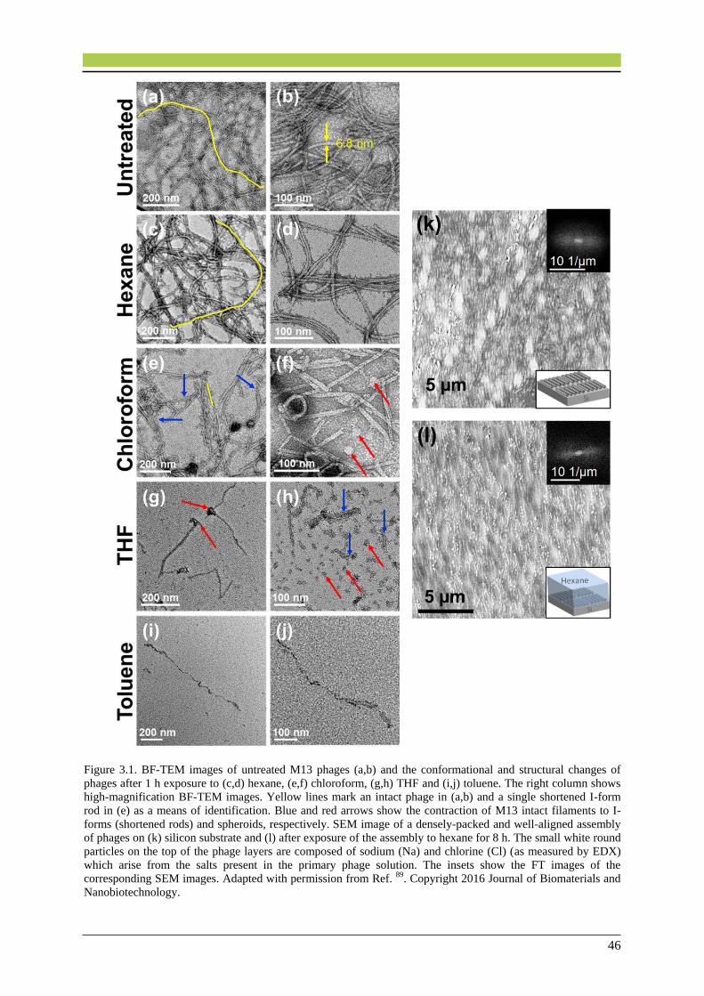
46
Figure 3.1. BF-TEM images of untreated M13 phages (a,b) and the conformational and structural changes of
phages after 1 h exposure to (c,d) hexane, (e,f) chloroform, (g,h) THF and (i,j) toluene. The right column shows
high-magnification BF-TEM images. Yellow lines mark an intact phage in (a,b) and a single shortened I-form
rod in (e) as a means of identification. Blue and red arrows show the contraction of M13 intact filaments to I-
forms (shortened rods) and spheroids, respectively. SEM image of a densely-packed and well-aligned assembly
of phages on (k) silicon substrate and (l) after exposure of the assembly to hexane for 8 h. The small white round
particles on the top of the phage layers are composed of sodium (Na) and chlorine (Cl) (as measured by EDX)
which arise from the salts present in the primary phage solution. The insets show the FT images of the
corresponding SEM images. Adapted with permission from Ref. 89. Copyright 2016 Journal of Biomaterials and
Nanobiotechnology.
47
This key finding is of high importance in virotronics, in which viruses are used as unique
biological entities to create advanced multi-component materials with a high molecular-level control.2
The functional properties of such devices, e.g. electrical35,101 and magnetic collective properties102 can
be maximized by using a self-assembled layer of organic molecules to spatially arrange inorganic
nanostructures.44 However, inorganic nanoparticles usually come in contact with organic templates in
the presence of an organic solvent. Therefore, hexane can be a great candidate for a dispersion
medium for the desired inorganic particles prior to them assembling into functional 2D films.
3.5. Conclusions
In closing, this study provides direct assessment of the stability of the filamentous M13 structure
when exposed to different organic solvents. Efforts to maintain the structural integrity of viruses leads
to an increased understanding of the factors that disrupt their structure. Phages showed to be
denatured in polar organic solvents as compared to nonpolar solvents. This phenomenon could be
understood by considering three factors: Solvent hydrogen-binding capacity, hydrophobicity and water
miscibility. This work also gives information on the handling of supramolecular assemblies in organic
solvents for virus-based materials. This can be used in the developing topic of research that is the
control of macromolecular assemblies with hierarchical frameworks.
Contributions to this chapter:
Pouya Moghimian and Benoit P. Pichon (Université de Strasbourg) designed the study. Pouya
Moghimian performed research. Sandra J. Facey (University of Stuttgart) prepared the phage
solutions. Christine Mollenhauer (MPI-IS) provided the organic solvents. Vesna Srot (MPI-
FKF) and Peter A. van Aken (MPI-FKF) jointly supervised this work. The published article
(Ref. 89) was written by Pouya Moghimian.
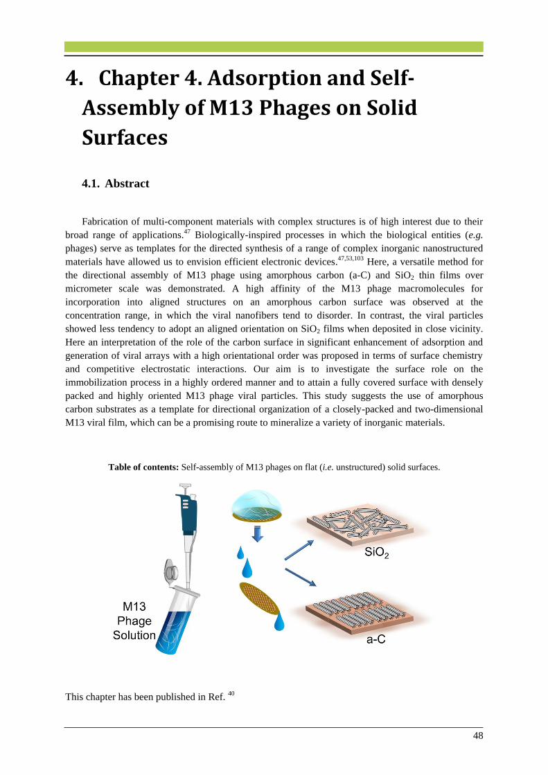
48
4. Chapter 4. Adsorption and Self-
Assembly of M13 Phages on Solid
Surfaces
4.1. Abstract
Fabrication of multi-component materials with complex structures is of high interest due to their
broad range of applications.47 Biologically-inspired processes in which the biological entities (e.g.
phages) serve as templates for the directed synthesis of a range of complex inorganic nanostructured
materials have allowed us to envision efficient electronic devices.47,53,103 Here, a versatile method for
the directional assembly of M13 phage using amorphous carbon (a-C) and SiO2 thin films over
micrometer scale was demonstrated. A high affinity of the M13 phage macromolecules for
incorporation into aligned structures on an amorphous carbon surface was observed at the
concentration range, in which the viral nanofibers tend to disorder. In contrast, the viral particles
showed less tendency to adopt an aligned orientation on SiO2 films when deposited in close vicinity.
Here an interpretation of the role of the carbon surface in significant enhancement of adsorption and
generation of viral arrays with a high orientational order was proposed in terms of surface chemistry
and competitive electrostatic interactions. Our aim is to investigate the surface role on the
immobilization process in a highly ordered manner and to attain a fully covered surface with densely
packed and highly oriented M13 phage viral particles. This study suggests the use of amorphous
carbon substrates as a template for directional organization of a closely-packed and two-dimensional
M13 viral film, which can be a promising route to mineralize a variety of inorganic materials.
Table of contents: Self-assembly of M13 phages on flat (i.e. unstructured) solid surfaces.
This chapter has been published in Ref. 40
49
4.2. Introduction
In order to induce the growth of uniform and homogeneous inorganic nanostructures, bio-assisted
synthesis methods are utilized as promising tools to attain organic–inorganic hierarchical nanolayers.
To this end, not only preparation of a densely packed layer of biological entities onto specific surfaces
is inevitable, but also achieving a directionally ordered pattern of the biological entities, extending
over a length scale is crucial to enhance the functional and physical properties of the final
product.35,41,43,101 The WT M13 phage has been the focus of many studies among the phages due to its
ability to template the formation of exquisite nanoinorganic material structures at room temperature.6
Several approaches have been undertaken to form well-ordered M13 viral structures.104 As an
example, Sawada et al. 31 have immobilized engineered M13 phages in an oriented manner onto an
poly(methyl methacrylate) (PMMA) film by dipping method. It has been stated that a higher
sweeping-up speed leads to a more ordered structure due to the higher capillary force acting at the
meniscus. Although several assembly attempts have been made for hybrid structures using modified
M13 phage recently, the study of the surface chemical key factors in directing the 2D order of WT
M13 viral particles has been overlooked.41,105 Wang et al.106 successfully assembled M13 phage
bundles on a poly(L-lysine) substrate. The alignment of M13 phages leads to well-ordered nanofibers,
which is of technological importance in piezoelectric generators.101 The piezoelectric strength of
directionally patterned phages was reported to intensify due to the dipole moment of the pVIII α-
helical structure.35,101 In general, the orientation of M13 viruses onto a substrate depends on phage
concentration, biomolecular interactions between the virion particles and external fields.17,38,107
However, not only the surface chemistry of the substrate but also other factors like the surface
roughness play prominent roles in protein adsorption and directional alignment.108,109 The influence of
different surface chemistries on the adsorption of M13 phages and their further alignment was less
studied up to now.
4.3. Materials and Methods
WT M13 phages were pipetted from viral solutions with different concentrations onto TEM grids
(~3 mm) covered by a carbon support film or a thermally grown silicon dioxide membrane, both with
a thickness of ~20 nm. Thereafter, the grids were directionally washed using Milli-Q water in order to
apply a shear force110 on the phage particles in a directed manner and to remove soluble salts from the
supporting films. Lastly, the specimens were negatively stained using 2% uranium acetate (UA) and
characterized by TEM. The Zeiss SESAM microscope was used to carry out TEM investigations. In
addition, STEM and EDX analysis were performed using the VG HB501UX STEM instrument.
Furthermore, the surface roughness of the films was measured by means of AFM NanoWizard II. The
contact angles of the SiO2 and a-C films were measured using the Krüss G10 contact angle
goniometer. The measured contact angles were an average on three different regions of each surface.
The concentration of phage solution was calculated by using the molecular weight of a phage
particle (12 × 106 Da).111 The initial phage concentrations and the corresponding liquid crystalline
regions are shown in Table 4.1.

50
Table 4.1. Phage concentrations used for macromolecular self-assembly on a-C and SiO2 thin films, estimated
from the molecular weight of phage particles. Reprinted with permission from Ref. 39. Copyright 2014
American Chemical Society.
Self-assembled structure Initial concentration (pfu/mL) Initial concentration (mg/mL)
Isotropic regiona 1.4 × 10¹³ 0.28
Nematic regionb 3.5 × 10¹⁴ 6.97
a Concentrations below 5 mg/ml.2 b Concentrations above 5 mg/ml.
4.4. Results and Discussion
In order to substantiate the role of the surface on the protein adsorption, the phage self-assembly
was studied in two liquid crystalline regions: in the extreme isotropic region and above the nematic
threshold. Initial investigation revealed that the low concentration of M13 phage solution (1.4 × 10¹³
pfu/ml) leads to the disordered phase of viral particles on the silicon dioxide surface (Figure 4.1a,b).
From this observation, it can be concluded that when the concentration of the primary viral solution is
below 5 mg/ml (2.51 × 10¹⁴ pfu/ml) (see Table 4.1) the trend of the system is towards the formation of
an isotropic phage distribution, which exhibits no orientational order.2,112 Phage bundles were
generated, which resulted in a decrease in the apparent concentration of filamentous particles. It has
been reported that phage bundling can disrupt the long-range phage orientation in the nematic
regime.106 Even though from Figure 4.1a,b the state of disorder was evident at the microscopic level, a
more accurate description and identification of the macromolecular arrangement of the prepared viral
films can be obtained by FT images. The insets in Figure 4.1a,b show the FT images for disordered
nanofibrous viruses, which show no preferential order and a round intensity profile. It should be noted
that the partial darkening effects of WT phages arise from the heavy metals in the UA solution used as
the staining agent. Figure 4.1c and d show BF-TEM images of WT M13 phages deposited on an a-C
film from a viral solution with the same concentration of 1.4 × 10¹³ pfu/ml. The FT images for aligned
viruses produce an intensity profile distributed in a broad elongated ellipse perpendicular to the virus
alignment. The a-C support film was covered with a packed layer of phages, suggesting a 2D stacking
upon the drying process on the carbon film. As seen in Figure 4.1d, single phages could be traced on
the top of the phage layer, which might be due to the electrostatic interaction between the phage
particles and the rather weak driving force for all the filamentous particles to point along the same
direction for low colloidal concentrations. The nanofibers are not perfectly aligned, yet they do have
some degree of alignment as confirmed by the FT images.
Next, the viral solution of a different phage concentration was deposited onto the a-C and SiO2
films. This was done to direct the liquid crystalline system to a phase transition from an isotropic to a
nematic phase on the supporting films. For this purpose, the phage concentration was increased to a
concentration above the nematic threshold (see Table 4.1).

51
Figure 4.1. (a) BF-TEM image of randomly distributed and bundled WT M13 phages immobilized on SiO2
membrane from a droplet of M13 viral solution (1.4 × 10¹³ pfu/ml). (b) High-magnification image of (a),
depicting a highly disorder and web-like structure. (c) BF-TEM image of WT M13 phages packed on a-C
support film from a droplet of M13 viral solution (1.4 × 10¹³ pfu/ml). (d) High-magnification image of (c),
showing the 2D alignment along a common direction. The insets show the FT images of the corresponding BF-
TEM images. The isotropic–nematic transition is visible from (b) to (d). Reprinted with permission from Ref. 40.
Copyright 2014 American Chemical Society.
Figure 4.2a,b and Figure 4.2c,d show BF-TEM images of WT M13 phages deposited on a-C
and SiO2 films respectively from a viral solution with the same concentration of 3.5 × 10¹⁴ pfu/ml. It
could be observed that a high directional phage alignment of the viral 2D film could be achieved on
the a-C film (cf. Figure 4.2a,b with Figure 4.2c,d). A closely packed and highly aligned M13 phage
viral film along a direction was obtained at the initial phage concentration of 3.5 × 10¹⁴ pfu/ml. This
was verified by the FT images showing a narrow and elongated ellipse perpendicular to the direction
of alignment (see insets in Figure 4.2c,d). This suggests the formation of a well-organized and uniform
viral film on the a-C surface. As shown in Figure 4.2b, an intertwined texture having a net degree of
alignment was detected on the SiO2 surface.
Small round-shaped particles, which were not dissolved in Milli-Q water during the washing
process, were also observed on surfaces. The presence of these particles, which might have emerged
from the viral solution, is due to buffer and salts remaining in the purified M13 phage solution and/or
the buffer used to disperse the viral particles in the aqueous medium.31,113. It could be hypothesized
that upon stacking of the very thin 2D nematic layer on the a-C surface, the small solution residues
have formed local agglomerates atop the phage layer, which could be prone to removal during the
washing process.
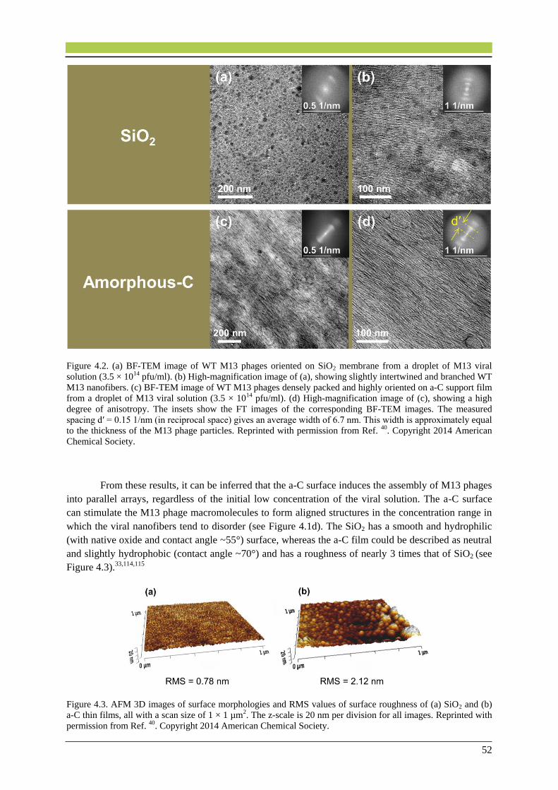
52
Figure 4.2. (a) BF-TEM image of WT M13 phages oriented on SiO2 membrane from a droplet of M13 viral
solution (3.5 × 10¹⁴ pfu/ml). (b) High-magnification image of (a), showing slightly intertwined and branched WT
M13 nanofibers. (c) BF-TEM image of WT M13 phages densely packed and highly oriented on a-C support film
from a droplet of M13 viral solution (3.5 × 10¹⁴ pfu/ml). (d) High-magnification image of (c), showing a high
degree of anisotropy. The insets show the FT images of the corresponding BF-TEM images. The measured
spacing d′ = 0.15 1/nm (in reciprocal space) gives an average width of 6.7 nm. This width is approximately equal
to the thickness of the M13 phage particles. Reprinted with permission from Ref. 40. Copyright 2014 American
Chemical Society.
From these results, it can be inferred that the a-C surface induces the assembly of M13 phages
into parallel arrays, regardless of the initial low concentration of the viral solution. The a-C surface
can stimulate the M13 phage macromolecules to form aligned structures in the concentration range in
which the viral nanofibers tend to disorder (see Figure 4.1d). The SiO2 has a smooth and hydrophilic
(with native oxide and contact angle ~55°) surface, whereas the a-C film could be described as neutral
and slightly hydrophobic (contact angle ~70°) and has a roughness of nearly 3 times that of SiO2 (see
Figure 4.3).33,114,115
Figure 4.3. AFM 3D images of surface morphologies and RMS values of surface roughness of (a) SiO2 and (b)
a-C thin films, all with a scan size of 1 × 1 µm2. The z-scale is 20 nm per division for all images. Reprinted with
permission from Ref. 40. Copyright 2014 American Chemical Society.

53
It has been reported that the state of hydrophobicity and the charge density can influence the
protein adsorption.116 For instance, it has been stated that the hydroxyl (OH–) groups of the SiO2
surface can function as adsorptive sites for positively-charged organic materials.117,118 In contrast to the
SiO2 surface, the hydrophobic nature of a-C causes weak interactions between the viral
macromolecules and the solid surface. This is believed to allow for the mobility of phages after
deposition and further directional stacking of the 2D viral film as a consequence. The estimated two-
dimensional phage number densities of the viral films on the a-C and SiO2 substrates were calculated
according to:
ρ(2D,est)𝐿2 = 𝐿 𝑃⁄ , 4.1
where L is the length of the thin rods and P is the center-to-center distance of two hypothetical parallel
cylinders of diameter 𝐷 ≤ 𝑃. The particle number densities of thin rods in two dimensions were
estimated from the intensity profiles of Figures 4.1d, 4.2b, and 4.2d to be 101.6, 125.7, and 130.6,
respectively. These values are considerably higher than the particle number density of thin hard rods in
two dimensions at the isotropic to nematic phase transition according to the Onsager model:119
ρ(2D,IN)𝐿2 = 4.7. 4.2
Hence, the ρ(2D,est) values are significantly higher than the ρ(2D,IN) due to the incubation of viral
solution on the thin films. Therefore, a two-dimensional nematic phase can be found in the
aforementioned Figures (Figures 4.1d, 4.2b, and 4.2d) similar to earlier result for amyloid fibrils of
comparable diameter.120
It has been demonstrated that a smooth surface hosts lower amounts of adsorbed proteins per
macroscopic area compared with a rough surface.114 It should be noted that a solid surface which has
a higher isoelectric point (pI) is a higher virus absorbent compared to those with a lower pI under the
same experimental conditions.116 The pI values of the a-C and SiO2 solids have been measured to be
7–9 and 1.9, respectively.33,121 As pointed out, hydroxyl groups present on the SiO2 surface115,122 might
influence the adsorption of organic residues from the viral solution.123 In an aqueous medium, the
phage coat proteins tend to fold in a way to expose their hydrophilic side chains on the surface while
shielding hydrophobic side chains. 116 Thus, on SiO2 films, M13 phages prefer to paste their bodies on
the surface firmly and this prevents the freedom of the viral particles to orient in a parallel fashion
when deposited in close vicinity. This is suggested to be the reason for the formation of slightly
branched arrays of phage fibers even at high concentrations of phage solutions (see Figure 4.2b).
Furthermore, as shown in Figure 4.1a,b, at low virus concentrations the bundle formation and
immobilization of phages upon the deposition process prevent their further alignment on the solid
film. Therefore, there is not enough driving force to dictate the self-assembly of the phages along a
direction even as a result of directional flow of Milli-Q water. Interestingly, the phage particles have
the ability to accumulate and orient themselves on the a-C thin film to some extent (see Figure 4.2c,d),
which could be merely attributed to the specific surface chemistry of a-C. The a-C thin films have
been shown to adsorb a substantially higher amount of human serum albumin, human blood plasma,
and antibodies compared to silicon.114 M13 phage is composed of amino acid residues with side chains
on its coat proteins. Contact sites between these amino acids and the surface allow for the adsorption
of proteins on the surface.124 On a-C films, a clear preference for the contact sites to align themselves
according to a common direction was observed. Although the complex correlation between the surface
hydrophobicity, roughness, interparticle forces, and external shear forces in nanoparticle assembly
needs further investigation, our hypothesis is that the high contact angle of the a-C surface and its high

54
isoelectric point are the keys for obtaining a high degree of phage alignment and different adsorption
responses at a specific phage concentration.
4.5. Conclusions
These results suggest a versatile approach that can be used to influence the mineralization of a
variety of inorganic nanostructure layers and therefore open up exciting opportunities for the
fabrication of organic–inorganic systems with nanoscale precision. This work demonstrated that, under
specific experimental conditions, amorphous carbon film is a promising host for a highly oriented
layer of M13 phages compared with silicon dioxide. The M13 phage particles were found to have a
high affinity for incorporation into a densely assembled pattern on a-C films. Such assemblies were
obtained by applying phage solution on the surface without employing nanoparticle assembly methods
such as dip coating or convective assembly. Obtaining a directionally organized monolayer of M13
phages is a challenge due to their extremely low thickness, flexibility, and high affinity for bundle
formation. Thus, this work sets the stage for a novel paradigm for biomolecular two dimensional self-
assembly. This has potential in the development of nanoscale scaffolds for bottom-up construction of
multicomponent devices. Future work will be performed to utilize the a-C-induced M13 phage film
with closely packed and oriented fashion to further fabricate multilayers of organic–inorganic
materials, which contain alternating virus-templated layers.
Contributions to this chapter:
Pouya Moghimian, Vesna Srot (MPI-FKF) and Dirk Rothenstein (University of Stuttgart)
designed the study. Pouya Moghimian performed the research. Sandra J. Facey (University of
Stuttgart) prepared the phage solutions. Ludger Harnau (MPI-IS) calculated the 2D phage
number densities. Markus Weiler (MPI-IS) did the AFM work. Stefan Kilper (MPI-IS)
measured the contact angles. Bernhard Hauer (University of Stuttgart), Joachim Bill
(University of Stuttgart) and Peter A. van Aken (MPI-FKF) jointly supervised this work. The
published article (Ref. 40) was written by Pouya Moghimian.
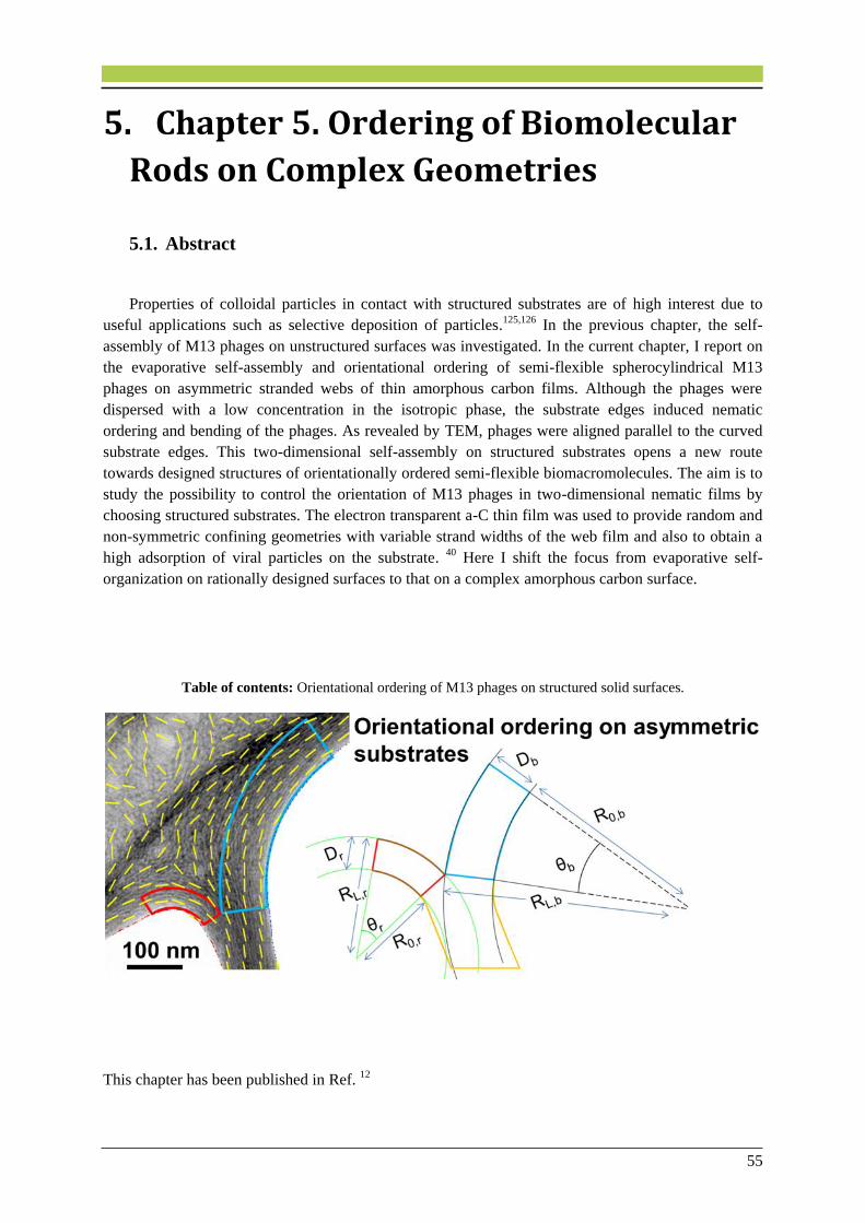
55
5. Chapter 5. Ordering of Biomolecular
Rods on Complex Geometries
5.1. Abstract
Properties of colloidal particles in contact with structured substrates are of high interest due to
useful applications such as selective deposition of particles.125,126 In the previous chapter, the self-
assembly of M13 phages on unstructured surfaces was investigated. In the current chapter, I report on
the evaporative self-assembly and orientational ordering of semi-flexible spherocylindrical M13
phages on asymmetric stranded webs of thin amorphous carbon films. Although the phages were
dispersed with a low concentration in the isotropic phase, the substrate edges induced nematic
ordering and bending of the phages. As revealed by TEM, phages were aligned parallel to the curved
substrate edges. This two-dimensional self-assembly on structured substrates opens a new route
towards designed structures of orientationally ordered semi-flexible biomacromolecules. The aim is to
study the possibility to control the orientation of M13 phages in two-dimensional nematic films by
choosing structured substrates. The electron transparent a-C thin film was used to provide random and
non-symmetric confining geometries with variable strand widths of the web film and also to obtain a
high adsorption of viral particles on the substrate. 40 Here I shift the focus from evaporative self-
organization on rationally designed surfaces to that on a complex amorphous carbon surface.
Table of contents: Orientational ordering of M13 phages on structured solid surfaces.
This chapter has been published in Ref. 12

56
5.2. Introduction
While various experimental studies,125,126,127,128 theoretical investigations,129,130 and computer
simulations 131,132 have been devoted to the understanding of the behavior of spherical colloidal
particles on structured substrates, only few studies have been aimed at the properties of rod-like or
worm-like particles in contact with such substrates, despite the importance of elongated particles for
both biological and materials applications.51,133,134,135,136,137,138 For instance, DNA separation studies
have been performed using a channel device that uses entropic trapping of DNA molecules.139,140,141
The entropic traps use substrates exhibiting a pattern consisting of rectangular blocks as a molecular
sieve. Also, the influence of geometrical surface patterns on the frictional properties of nanowire-
based lubrication systems has been investigated.142 It has been demonstrated that nanowires can act as
effective lubricants on structured substrates. Recently, Dammone et al.143 studied the splay-to-blend
transition of fluorescently labelled fd viruses confined to channels with wedge-structured walls having
different wedge opening angles using laser scanning confocal microscopy. As compared with fluids
consisting of spherical particles, studies of elongated semi-flexible molecules in contact with
structured substrates are obviously more difficult due to the additional orientational and
conformational degrees of freedom. To our knowledge, no work has been performed yet to trap semi-
flexible spherocylinders in asymmetric restricted spaces. Studying such systems can provide insights
into the influence of confinement on physical properties of soft matter.
M13 phages can be treated as polymer chains composed of homogeneous elastic material, where
the persistence length characterizes the molecular stiffness. Therefore, suspensions containing M13
phages are considered to be ideal model systems for studying properties of soft condensed matter
systems.144 Spontaneous assembly of such colloidal particles can be achieved by evaporation of the
phage-containing solution on a substrate.145,146 Such evaporative assemblies have been successfully
used in a number of different ways.147 For instance, sessile droplets of a colloidal suspension can be
evaporated on structureless mesoscale solid surfaces or on rationally designed spaces, i.e., flat thin
cells,147 wedge geometries,146 cylindrical channels,87 or under the influence of external fields such as
the frictional force.14
Here I study the self-organization and bending of M13 phages resulting from confinement on
irregular stranded webs of thin a-C films using the Zeiss TEM and theoretical considerations. The aim
is to study the possibility to control the orientation of M13 phages in two-dimensional nematic films
by choosing structured substrates. The electron transparent a-C thin film was used to provide random
and non-symmetric confining geometries with variable strand widths of the web film and also to
obtain a high adsorption of viral particles on the substrate.40 As a prerequisite for the present study we
have ensured in chapter 4, that self-assembly and ordering of M13 phages on unstructured substrates
takes place not only on a-C support films, but also on SiO2 membranes.40 Hence, I do not consider the
self-organization process discussed in the following as a specific phenomenon of the supporting a-C
web films.
5.3. Materials and Methods
WT M13 phage particles were generated and suspended in TBS at pH 7.4. A viral solution with a
concentration of 0.2 mg/ml was prepared according to our previously reported method.40 A 4 µl
droplet of WT M13 phages was incubated for 5 min onto a copper grid coated with an a-C web film
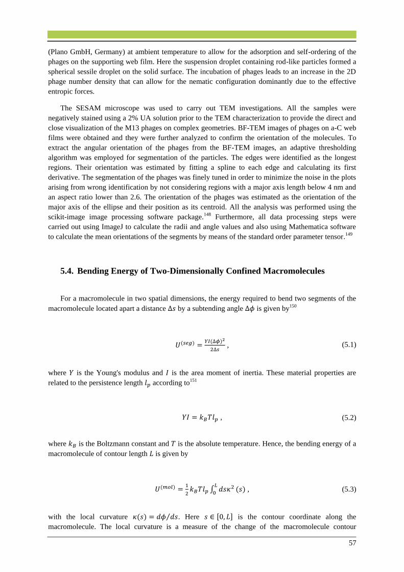
57
(Plano GmbH, Germany) at ambient temperature to allow for the adsorption and self-ordering of the
phages on the supporting web film. Here the suspension droplet containing rod-like particles formed a
spherical sessile droplet on the solid surface. The incubation of phages leads to an increase in the 2D
phage number density that can allow for the nematic configuration dominantly due to the effective
entropic forces.
The SESAM microscope was used to carry out TEM investigations. All the samples were
negatively stained using a 2% UA solution prior to the TEM characterization to provide the direct and
close visualization of the M13 phages on complex geometries. BF-TEM images of phages on a-C web
films were obtained and they were further analyzed to confirm the orientation of the molecules. To
extract the angular orientation of the phages from the BF-TEM images, an adaptive thresholding
algorithm was employed for segmentation of the particles. The edges were identified as the longest
regions. Their orientation was estimated by fitting a spline to each edge and calculating its first
derivative. The segmentation of the phages was finely tuned in order to minimize the noise in the plots
arising from wrong identification by not considering regions with a major axis length below 4 nm and
an aspect ratio lower than 2.6. The orientation of the phages was estimated as the orientation of the
major axis of the ellipse and their position as its centroid. All the analysis was performed using the
scikit-image image processing software package.148 Furthermore, all data processing steps were
carried out using ImageJ to calculate the radii and angle values and also using Mathematica software
to calculate the mean orientations of the segments by means of the standard order parameter tensor.149
5.4. Bending Energy of Two-Dimensionally Confined Macromolecules
For a macromolecule in two spatial dimensions, the energy required to bend two segments of the
macromolecule located apart a distance Δ𝑠 by a subtending angle ∆𝜙 is given by150
𝑈(𝑠𝑒𝑔) =𝑌𝐼(∆𝜙)2
2∆𝑠 , (5.1)
where 𝑌 is the Young's modulus and 𝐼 is the area moment of inertia. These material properties are
related to the persistence length 𝑙𝑝 according to151
𝑌𝐼 = 𝑘𝐵𝑇𝑙𝑝 , (5.2)
where 𝑘𝐵 is the Boltzmann constant and 𝑇 is the absolute temperature. Hence, the bending energy of a
macromolecule of contour length 𝐿 is given by
𝑈(𝑚𝑜𝑙) =1
2𝑘𝐵𝑇𝑙𝑝 ∫ 𝑑𝑠𝜅2𝐿
0(𝑠) , (5.3)
with the local curvature 𝜅(𝑠) = 𝑑𝜙 𝑑𝑠⁄ . Here 𝑠 ∈ [0, 𝐿] is the contour coordinate along the
macromolecule. The local curvature is a measure of the change of the macromolecule contour

58
direction as a function of the contour parameter. To simplify the calculation of the bending energy, a
convenient representation of the contour of the macromolecules and their curvature is required. Here I
consider the contour to be represented by a function 𝑦(𝑥) in a two-dimensional Cartesian coordinate
system. For an analytical function 𝑦(𝑥) the local curvature is given by
𝜅(𝑥) =𝑑2𝑦
𝑑𝑥2(1 + (
𝑑𝑦
𝑑𝑥)
2)
−3
2
, (5.4)
because of 𝑑𝜙 𝑑𝑠⁄ = tan 𝜙 and 𝑑𝑠2 = 𝑑𝑥2 + 𝑑𝑦2. Hence, the bending energy in Eq. (5.3) can be
written as
𝑈(𝑚𝑜𝑙) =1
2𝑘𝐵𝑇𝑙𝑝 ∫ 𝑑𝑥
𝑥𝐿
𝑥0(
𝑑2𝑦
𝑑𝑥2)2
(1 + (𝑑𝑦
𝑑𝑥)
2)
−5
2
, (5.5)
where the Cartesian coordinates (𝑥, 𝑦) of the two ends of the macromolecule at 𝑠 = 0 and 𝑠 = 𝐿 are
given by (𝑥𝐿 , 𝑦(𝑥𝐿)), respectively. In the case of a contour given by an arc of radius 𝑅 and subtending
an angle 𝜃 with the circle center, Eq. (5.5) reduces to
𝑈(𝑚𝑜𝑙) = 𝑘𝐵𝑇𝑙𝑝𝜃
2𝑅 , (5.6)
since 𝑦2(𝑥) = 𝑅2 − 𝑥2 and 𝐿 = 𝜃𝑅. Hence, the bending energy associated with an arc is inversely
proportional to the radius for a fixed angle subtended by the arc. On the basis of the bending energy
given in Eqs. (5.3) and (5.5), properties of individual semi-flexible macromolecules such as
DNA,152,153 amyloid fibrils,154,155 and unfolded proteins156,157 have been extracted from two-
dimensional atomic force and scanning tunneling microscopy images. However, the deposition
method under consideration here organizes M13 phages into dense two-dimensional bundles where
individual phages are closely packed. To provide a simple expression for the total bending energy of
such a two-dimensional bundle consisting of N phages I consider a bundle shape given by an annulus
sector of angle 𝜃 bounded by two concentric arcs of radii 𝑅0 and 𝑅𝐿 = 𝑅0 + (𝑁 − 1)𝑑, where 𝑑 is the
diameter of the phages. Using Eq. (5.6) the resulting bending energy is given by
𝑈(𝑎𝑛𝑛) = 𝑘𝐵𝑇
𝑙𝑝𝜃
2∑
1
𝑅0+𝑛𝑑𝑁−1𝑛=0 = 𝑘𝐵𝑇
𝑙𝑝𝜃
2𝑑(𝜓 (𝑁 +
𝑅0
𝑑) − 𝜓 (
𝑅0
𝑑)) ≈ 𝑘𝐵𝑇
𝑙𝑝𝜃
2𝑑ln (
𝑅𝐿+𝑑
𝑅0)
, (5.7)
where 𝜓(𝑧) is the digamma function.158 Hence for given phage persistence length 𝑙𝑝 and diameter 𝑑
the bending energy in Eq. (5.7) depends on the three parameters 𝑅0, 𝑅𝐿, and 𝜃.
𝑅0 ≫ 𝑑

59
5.5. Results and Discussion
As shown in Figure 5.1a, the thickness of the supporting substrates of pure amorphous carbon web
films with irregular and random strands was measured using EFTEM thickness mapping, based on the
log-ratio method which gives the ratio of the characteristic mean free path λ for inelastic scattering of
the material to the specimen thickness t.159 The mean free path was calculated using a mean free path
estimator script implemented in Digital Micrograph© (Gatan).160 For the amorphous carbon films used
in our experiments, a mean free path of 132.4 nm was determined. The corresponding t/λ map shows
the analyzed area (see Figure 5.1b) to be relatively uniform, with a mean thickness of ~23 nm of the
substrate film and at the edges (collar) up to ~55 nm. The sudden increase in thickness at the film
edges might be due to bending of the thin film at the free-standing boundaries.
Figure 5.1. Thickness estimation of the carbon supporting film with a web-like 2D topology and randomly
dispersed holes (black areas in (a)). (a) The EFTEM thickness map of the carbon web film. A line profile with an
integration width of 40 nm (yellow rectangle) was taken from the area indicated to estimate the material’s
average thickness over the referred area. (b) The relative thickness profile (t/λ) along the length of the yellow
rectangle in (a). The mean thickness of the film was measured to be ~23 nm on the flat surface and up to ~ 55
nm at the collar. The noise in the intensity profile might arise from the roughness of the carbon surface. (c) BF-
TEM image of randomly oriented M13 particles on the a-C flat surface far from the surface edges and
intersections. The inset shows the 2D FT image of the BF-TEM image confirming that the M13 phages formed
an isotropic arrangement. The partial darkening of the phages is due to the heavy metals in the UA solution.
Reproduced from Ref. 12 with permission from The Royal Society of Chemistry.
To study the effect of irregular spatial confinement on long semi-flexible M13 phages and
their bending behavior, the phages were deposited onto carbon web films with asymmetric shapes. In
the current chapter, unless otherwise stated, the term “surface” refers to the surface of the substrate
solid phase that creates an interface with the phages. First, phage particles from a viral solution were
incubated onto the surface. As seen in Figure 5.1c, on the structureless and wide surface areas far
enough from the surface boundaries, the phages exhibit random orientations confirmed by the round
intensity pattern with no preferential order of the FT image. In contrast, a close examination of the
TEM images revealed that a significant morphological evolution occurred in the intersections where
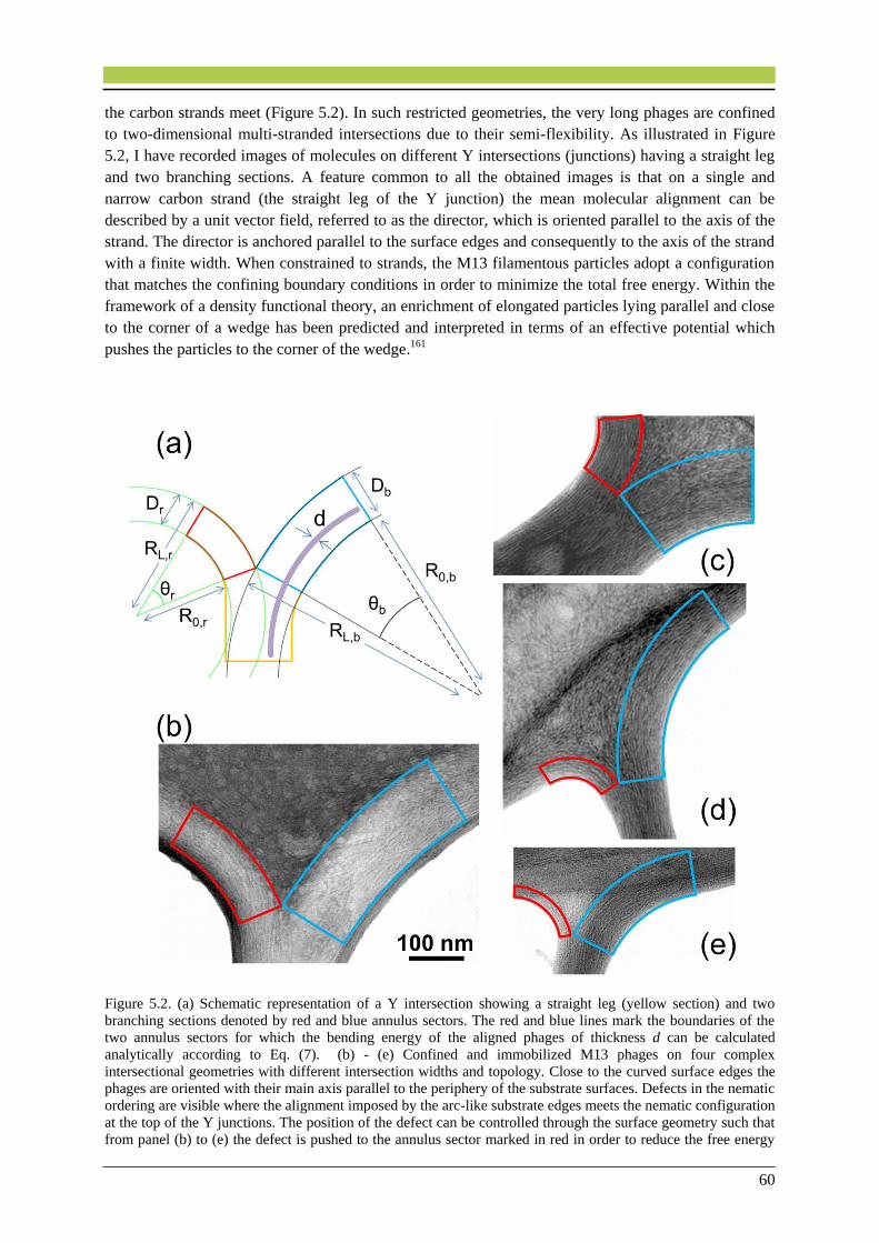
60
the carbon strands meet (Figure 5.2). In such restricted geometries, the very long phages are confined
to two-dimensional multi-stranded intersections due to their semi-flexibility. As illustrated in Figure
5.2, I have recorded images of molecules on different Y intersections (junctions) having a straight leg
and two branching sections. A feature common to all the obtained images is that on a single and
narrow carbon strand (the straight leg of the Y junction) the mean molecular alignment can be
described by a unit vector field, referred to as the director, which is oriented parallel to the axis of the
strand. The director is anchored parallel to the surface edges and consequently to the axis of the strand
with a finite width. When constrained to strands, the M13 filamentous particles adopt a configuration
that matches the confining boundary conditions in order to minimize the total free energy. Within the
framework of a density functional theory, an enrichment of elongated particles lying parallel and close
to the corner of a wedge has been predicted and interpreted in terms of an effective potential which
pushes the particles to the corner of the wedge.161
Figure 5.2. (a) Schematic representation of a Y intersection showing a straight leg (yellow section) and two
branching sections denoted by red and blue annulus sectors. The red and blue lines mark the boundaries of the
two annulus sectors for which the bending energy of the aligned phages of thickness d can be calculated
analytically according to Eq. (7). (b) - (e) Confined and immobilized M13 phages on four complex
intersectional geometries with different intersection widths and topology. Close to the curved surface edges the
phages are oriented with their main axis parallel to the periphery of the substrate surfaces. Defects in the nematic
ordering are visible where the alignment imposed by the arc-like substrate edges meets the nematic configuration
at the top of the Y junctions. The position of the defect can be controlled through the surface geometry such that
from panel (b) to (e) the defect is pushed to the annulus sector marked in red in order to reduce the free energy
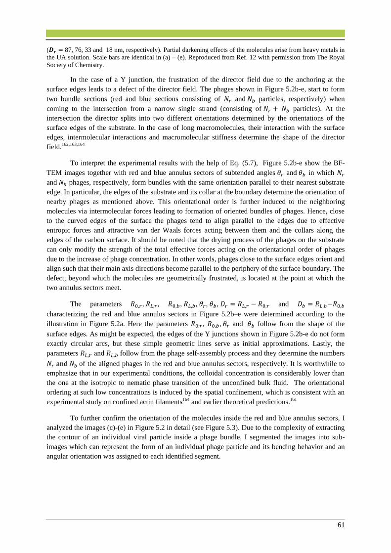
61
(𝑫𝒓 = 87, 76, 33 and 18 nm, respectively). Partial darkening effects of the molecules arise from heavy metals in
the UA solution. Scale bars are identical in (a) – (e). Reproduced from Ref. 12 with permission from The Royal
Society of Chemistry.
In the case of a Y junction, the frustration of the director field due to the anchoring at the
surface edges leads to a defect of the director field. The phages shown in Figure 5.2b-e, start to form
two bundle sections (red and blue sections consisting of 𝑁𝑟 and 𝑁𝑏 particles, respectively) when
coming to the intersection from a narrow single strand (consisting of 𝑁𝑟 + 𝑁𝑏 particles). At the
intersection the director splits into two different orientations determined by the orientations of the
surface edges of the substrate. In the case of long macromolecules, their interaction with the surface
edges, intermolecular interactions and macromolecular stiffness determine the shape of the director
field.162,163,164
To interpret the experimental results with the help of Eq. (5.7), Figure 5.2b-e show the BF-
TEM images together with red and blue annulus sectors of subtended angles 𝜃𝑟 and 𝜃𝑏 in which 𝑁𝑟
and 𝑁𝑏 phages, respectively, form bundles with the same orientation parallel to their nearest substrate
edge. In particular, the edges of the substrate and its collar at the boundary determine the orientation of
nearby phages as mentioned above. This orientational order is further induced to the neighboring
molecules via intermolecular forces leading to formation of oriented bundles of phages. Hence, close
to the curved edges of the surface the phages tend to align parallel to the edges due to effective
entropic forces and attractive van der Waals forces acting between them and the collars along the
edges of the carbon surface. It should be noted that the drying process of the phages on the substrate
can only modify the strength of the total effective forces acting on the orientational order of phages
due to the increase of phage concentration. In other words, phages close to the surface edges orient and
align such that their main axis directions become parallel to the periphery of the surface boundary. The
defect, beyond which the molecules are geometrically frustrated, is located at the point at which the
two annulus sectors meet.
The parameters 𝑅0,𝑟, 𝑅𝐿,𝑟, 𝑅0,𝑏, 𝑅𝐿,𝑏, 𝜃𝑟, 𝜃𝑏, 𝐷𝑟 = 𝑅𝐿,𝑟 − 𝑅0,𝑟 and 𝐷𝑏 = 𝑅𝐿,𝑏−𝑅0,𝑏
characterizing the red and blue annulus sectors in Figure 5.2b–e were determined according to the
illustration in Figure 5.2a. Here the parameters 𝑅0,𝑟, 𝑅0,𝑏, 𝜃𝑟 and 𝜃𝑏 follow from the shape of the
surface edges. As might be expected, the edges of the Y junctions shown in Figure 5.2b-e do not form
exactly circular arcs, but these simple geometric lines serve as initial approximations. Lastly, the
parameters 𝑅𝐿,𝑟 and 𝑅𝐿,𝑏 follow from the phage self-assembly process and they determine the numbers
𝑁𝑟 and 𝑁𝑏 of the aligned phages in the red and blue annulus sectors, respectively. It is worthwhile to
emphasize that in our experimental conditions, the colloidal concentration is considerably lower than
the one at the isotropic to nematic phase transition of the unconfined bulk fluid. The orientational
ordering at such low concentrations is induced by the spatial confinement, which is consistent with an
experimental study on confined actin filaments164 and earlier theoretical predictions.161
To further confirm the orientation of the molecules inside the red and blue annulus sectors, I
analyzed the images (c)-(e) in Figure 5.2 in detail (see Figure 5.3). Due to the complexity of extracting
the contour of an individual viral particle inside a phage bundle, I segmented the images into sub-
images which can represent the form of an individual phage particle and its bending behavior and an
angular orientation was assigned to each identified segment.

62
Figure 5.3. Mean orientations of the particles (marked with yellow lines) extracted from the analysis of the
images (c) - (e) in Figure 5.2. The mean orientation diagrams are superimposed on the raw TEM images
showing that within the assumed annulus sectors the molecules tend to align parallel to their closest surface
edge. The orientations are calculated by averaging over the orientation of the particles within circular domains of
radius 20 nm. Scale bars are identical. Reproduced from Ref. 12 with permission from The Royal Society of
Chemistry.
Figure 5.2 and 5.3 illustrate that the position of the defect can be controlled through the
surface geometry. In general, with increasing ratio 𝑅0,𝑏/𝑅0,𝑟 and fixed angles of the annulus sectors
the defect is pushed toward the annulus sector marked in red in order to reduce the total bending
energy [Eq. (5.7)] of the phages located in the red annulus sector. Therefore, the resulting director
fields given by the orientation of the phages are non-symmetric while rather symmetric director fields
have been found for worm-like fd particles confined by symmetric wedges 143 and for carbon
nanotubes close to flat substrates.165,166,167 The radii 𝑅0,𝑟, 𝑅0,𝑏 , 𝑅𝐿,𝑟 , 𝑅𝐿,𝑏 for the red and blue sectors
of all BF-TEM images in Figure 5.2 and the ratios 𝛿 = (𝑅𝐿,𝑟 − 𝑅0,𝑟) (𝑅𝐿,𝑏 − 𝑅0,𝑏)⁄ for red and blue
sections are presented in Table 5.1. From the table, it is apparent that the ratio of the width of the red
sector to the width of the blue sector decreases from Figure 5.2b to e.
Table 5.1. Radii 𝑹𝟎,𝒓, 𝑹𝟎,𝒃, 𝑹𝑳,𝒓, 𝑹𝑳,𝒃 characterizing the red and blue annulus sectors in Figs. 5.2b–e, and the
ratios 𝜹 = (𝑹𝑳,𝒓 − 𝑹𝟎,𝒓) (𝑹𝑳,𝒃 − 𝑹𝟎,𝒃)⁄ . Reproduced from Ref. 12 with permission from The Royal Society of
Chemistry.
Radius 𝒂𝒃
(nm) (b) (c) (d) (e)
𝑹𝟎,𝒓 290−15 123 72 90
𝑹𝟎,𝒃 697−18 264 289 200
𝑹𝑳,𝒓 377−3 199+12 105−7 108+5
𝑹𝑳,𝒃 836+3 395−12 373+7 281−5
𝜹𝒂𝒃
0.63−0.03 0.58+0.16 0.39−0.10 0.22+0.08
a,b Upper and lower deviation limits, respectively, in the radii and 𝛿 values.
Equations (5.1) – (5.7) presented above are applicable to macromolecules that can be modeled
as homogeneous worm-like objects. At the protein level, M13 phages are not homogeneous, but the

63
surface-induced phage bending deformations occur on a larger length scales, because 𝑅0,𝑟, 𝑅0,𝑏 , 𝑅𝐿,𝑟 ,
𝑅𝐿,𝑏 ∈ [72 − 836] nm for the samples shown in Figure 5.2. Therefore, the equations presented here
can be applied to the M13 phages keeping in mind that approximating the edges of the amorphous
carbon surface as circular arcs represents an oversimplification.
This, however, allows one to derive analytic expressions for the bending energy. In order to
understand the values of the larger radii 𝑅𝐿,𝑏 = 𝑅0,𝑏 + (𝑁𝑏 − 1)𝑑 and 𝑅𝐿,𝑟 = 𝑅0,𝑟 + (𝑁𝑟 − 1)𝑑 of the
blue and red annulus sectors displayed in Figure 5.2, it is helpful to consider the free energy
𝐹 = 𝑈𝑏(𝑎𝑛𝑛) + 𝑈𝑟
(𝑎𝑛𝑛) − 𝑇𝑆 . (5.8)
Here 𝑈𝑟(𝑎𝑛𝑛) and 𝑈𝑏
(𝑎𝑛𝑛) are the bending energies of the red and blue annulus sector of a Y
junction calculated according to Eq. 5.7 and 𝑆 is the entropy. To compute the entropy 𝑆 = 𝑘𝐵 𝑙𝑛 Ω due
to orienting 𝑁𝑟 phages to the left and 𝑁𝑏 phages to the right at a Y junction, one has to deduce the
number of states according to Ω = (𝑁𝑟 + 𝑁𝑏)!/(𝑁𝑟! 𝑁𝑏!). Hence the last term in Eq. (5.8) exhibits a
minimum at 𝑁𝑟 = 𝑁𝑏 corresponding to an equal number of phages oriented to the left and to the right
at a Y junction. However, the sum of the first two terms in Eq. 5.8 exhibits a minimum at 𝑁𝑟 ≠ 𝑁𝑏 for
two arc-like edges of different shape, i.e., 𝑅0,𝑟 ≠ 𝑅0,𝑏 and 𝜃𝑟 ≠ 𝜃𝑏, where 𝜃𝑟 and 𝜃𝑏 are the angles of
the red and blue annulus sectors, respectively. Therefore, minimization of 𝐹 leads in general to
different values of 𝑁𝑟 and 𝑁𝑏 in line with the experimental results shown in Figure 5.2. Nevertheless,
the simple theoretical approach provides an explanation for the different values of 𝑁𝑟 and 𝑁𝑏.
Properties of the system are characterized by the free energy which includes both energetic and
entropic contributions. The competition of these contributions determines the resulting structures.
Understanding the orientational behavior of phages on complex geometries of carbon web films
can offer the active use of topological defects in controlling of liquid crystal flow, because the
presence of topological defects strongly affects the flow of liquid crystals which elastically interact
with surfaces.168 Besides, our results could be used in the application of liquid crystals (e.g. memory
effects) in topological manifolds which have interconnected porous media,169,170 similar to our carbon
web films.
5.6. Conclusions
In this chapter, I studied semi-flexible M13 phages in contact with irregular stranded webs of thin
a-C films using TEM and theoretical considerations. In this work, I showed that on the structureless
and wide surface areas far from the a-C surface edges, the phages exhibited random orientations.
However, the orientation of M13 phages in two-dimensional nematic films was controlled by the
orientation and curvature of the substrate edges. When constrained to surface strands, the M13 phages
adopted a configuration that matches the confining boundary conditions in order to minimize the total
free energy. An annulus sector was superimposed on these oriented phage bundles that allowed us to
derive analytic expressions for the bending energy of such oriented bundles. Our theoretical approach
provides an explanation for the different number of phages orienting close to the surface edges with
different local curvatures. By comparing the self-assembly on differently shaped a-C substrates, it was
demonstrated that the alignment of the phages can be controlled by choosing appropriate substrate

64
shapes. This offers a convenient means to fabricate designed structures of orientationally ordered M13
phages. The understanding of such systems opens up new possibilities for defect engineering of liquid
crystals which can be beneficial for the applications of liquid crystals in the presence of surface
microscopic pores and irregularities.
Contributions to this chapter:
Pouya Moghimian and Ludger Harnau (MPI-IS) designed the study. Pouya Moghimian
performed the research. Sandra J. Facey and Bernhard Hauer (University of Stuttgart)
prepared the phage solutions. Francisco de la Pena (University of Cambridge) carried out
image analysis. Nima Farahmand Bafi and Pouya Moghimian analyzed the data. Ludger
Harnau, Vesna Srot (MPI-FKF) and Peter A. van Aken (MPI-FKF) jointly supervised this
work. The published article (Ref. 12) was written by Pouya Moghimian and Ludger Harnau.

65
6. Chapter 6. Biomineralization and
Biotemplated Synthesis of Organic–
Inorganic Hybrid Multilayers
6.1. Abstract
Bio-inspired fabrication of organic–inorganic nano-hybrid structures, where inorganic
nanomaterials are templated by the organic component, i.e. biological entities, is of high interest due
to the broad range of applications of these structures.43,47,53,103,171 Protein-based bottom-up synthesis of
functional nanomaterials and devices is one of the most promising areas in bio-nanotechnology. Here,
I demonstrate that organic assemblies can serve as biologically controllable scaffolds for the
deposition of inorganic nanoparticles. In this work, I used our findings presented in the chapter 4 and I
employed a C-sputtered substrate to assemble densely-packed wild-type M13 phages for the controlled
mineralization of ZnO particles. Our aim was to construct layered structures consisting of organic and
inorganic materials which contain alternating layers on a smooth substrate. The microstructure,
elemental composition, and also the integrity of the organic and the biologically-templated inorganic
layers were studied. A uniform nano-hybrid structure without significant thickness fluctuations was
fabricated by using a high concentration of M13 phages and a carbon-coated substrate. The current
study gives insight into the combination of organic–inorganic materials into a multilayered structure,
which could be used as a constituent in electronic devices such as transistors.
Table of contents: Assembly of M13-ZnO bilayered structures.
Part of this chapter has been published in Ref. 58

66
6.2. Introduction
Different mechanisms can be adopted from nature to trigger the nucleation and growth of desired
inorganic nanostructures and consequently to obtain organic–inorganic hierarchical nanostructures, in
which the organic nanocomponents are considered as the scaffolds.172 The WT M13 phage has been
the focus of extensive studies owing to its well-defined structure for protein-based scaffolds and also
its ability to mineralize nano-inorganic materials at ambient temperature.173 The coat proteins of the
viral particles can be genetically engineered for a specific inorganic target to allow for selective
nucleation and growth of the desired inorganic materials. Also, the high aspect ratio of M13 phages
makes them attractive templates for the fabrication of inorganic nanowires. M13 phages have recently
been engineered to specifically synthesize gold nanoparticles,174 cadmium selenide,53 copper sulfide18
and barium titanate55 nanocrystals. However, non-modified and non-engineered viruses are still able to
template the deposition of inorganic materials and thus they can be used to fabricate a variety of
complex hybrid nanostructures.47 For instance, the tobacco mosaic viruses (TMV) have been reported
to mineralize zinc oxide (ZnO) from a deposition solution.57 This allows us to fabricate intelligent, i.e.
responsive, organic–inorganic systems with desired properties that have high potential for use in field-
effect transistors.57 Such layered structures containing alternating organic and inorganic layers also
showed enhancements in photoconductivity and mechanical properties compared to only inorganic
monolayers.175,176 The study of the integrity and elemental composition of the layers and the interfaces
could lead to a more precise control over the properties of such structures.
6.3. Materials and Methods
Two viral solutions with concentrations of 1.4 × 10¹³ and 3.5 × 10¹⁴ pfu/ml were prepared in TBS
buffer. The convective assembly technique, was used to deposit the filamentous M13 phages onto the
smooth Si and C-coated Si surfaces. To form viral layers on the surfaces, the viral particles were
deposited by pulling a meniscus containing the virus solution with a specific concentration across the
substrate at a constant rate (1.2 mm/min) using a motion control system. The glass cover slips and the
silicon wafers (1.5 × 1.5 cm) that were used in the deposition process were cleaned by consecutive
sonication in Milli-Q water and a mixture of 1:1 acetone:ethanol and they were finally dried
under N2 flow prior to use.177 The coating of homogeneous 40 nm carbon on the silicon wafers was
carried out under high vacuum using a magnetron sputtering system (FMK) at room temperature.
The ZnO deposition solution was prepared according to the previously reported procedure.57,178
Briefly, equimolar methanol solutions of zinc acetate dihydrate (Zn(OOCCH3)2 ∙ 2H2O) (puriss. p.a.,
Fluka), polyvinylpyrrolidone (PVP) (PVP10, M = 10 000, Sigma-Aldrich), and tetraethylammonium
hydroxide (TEAOH) (purum, Fluka, ~25 % in methanol) were used to prepare the ZnO
deposition solution. The viral films immobilized on C-coated Si wafers were immersed in the ZnO
deposition solution and incubated in an oil bath for 1.5 h at 60 °C to complete one deposition cycle.
After the deposition cycle, methanol (VLSI Selectipur, BASF) was used to vigorously wash the wafer
surface and to remove all the unbound ZnO particles. Thereafter, the wafer was dipped in fresh
deposition solution for the next deposition cycle.
SE images were acquired by the Zeiss DSM 982 Gemini SEM operating at 3 kV. Samples that had
not undergone the mineralization process were coated with a thin (< 1 nm) layer of PtPd using the
sputter coater (Cressington, 208 HR) prior to the SEM investigations. The surface roughness of the
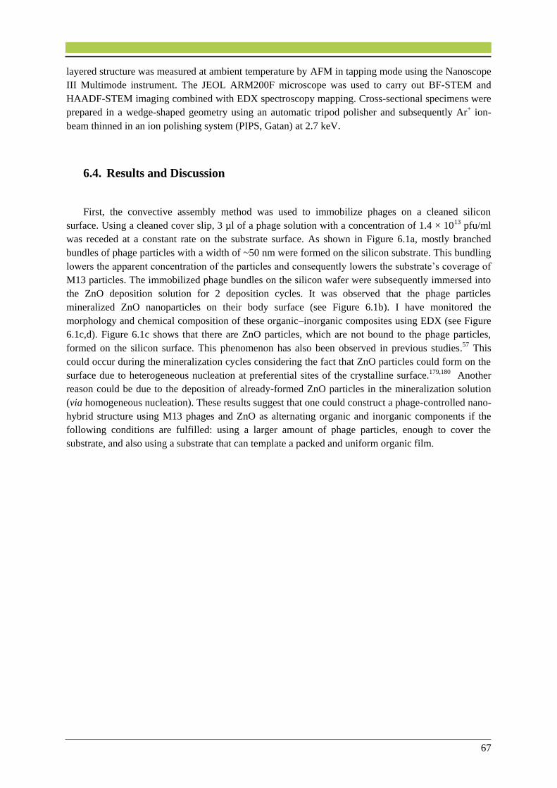
67
layered structure was measured at ambient temperature by AFM in tapping mode using the Nanoscope
III Multimode instrument. The JEOL ARM200F microscope was used to carry out BF-STEM and
HAADF-STEM imaging combined with EDX spectroscopy mapping. Cross-sectional specimens were
prepared in a wedge-shaped geometry using an automatic tripod polisher and subsequently Ar+ ion-
beam thinned in an ion polishing system (PIPS, Gatan) at 2.7 keV.
6.4. Results and Discussion
First, the convective assembly method was used to immobilize phages on a cleaned silicon
surface. Using a cleaned cover slip, 3 µl of a phage solution with a concentration of 1.4 × 10¹³ pfu/ml
was receded at a constant rate on the substrate surface. As shown in Figure 6.1a, mostly branched
bundles of phage particles with a width of ~50 nm were formed on the silicon substrate. This bundling
lowers the apparent concentration of the particles and consequently lowers the substrate’s coverage of
M13 particles. The immobilized phage bundles on the silicon wafer were subsequently immersed into
the ZnO deposition solution for 2 deposition cycles. It was observed that the phage particles
mineralized ZnO nanoparticles on their body surface (see Figure 6.1b). I have monitored the
morphology and chemical composition of these organic–inorganic composites using EDX (see Figure
6.1c,d). Figure 6.1c shows that there are ZnO particles, which are not bound to the phage particles,
formed on the silicon surface. This phenomenon has also been observed in previous studies.57
This
could occur during the mineralization cycles considering the fact that ZnO particles could form on the
surface due to heterogeneous nucleation at preferential sites of the crystalline surface.179,180 Another
reason could be due to the deposition of already-formed ZnO particles in the mineralization solution
(via homogeneous nucleation). These results suggest that one could construct a phage-controlled nano-
hybrid structure using M13 phages and ZnO as alternating organic and inorganic components if the
following conditions are fulfilled: using a larger amount of phage particles, enough to cover the
substrate, and also using a substrate that can template a packed and uniform organic film.

68
Figure 6.1. Plan-view SEM images of (a) adsorbed M13 phage bundles from a 3 µl phage solution with a
concentration of 1.4 × 10¹³ pfu/ml on a cleaned Si surface. (b) Mineralized ZnO nanoparticles on the phage
particles. (c) A single magnified phage bundle that mineralized ZnO nanoparticles with a diameter of ~10 nm.
(d) EDX spectrum obtained from a phage bundle with the mineralized ZnO nanoparticles. The background is due
to the Bremsstrahlung X-rays. Adapted from the Ref. 58 from the International Journal of Materials Research,
IJMR 2016, © Carl Hanser Verlag, München.
To successfully develop a layered structure, 5.5 µl of a phage solution with a concentration of
3.5 × 10¹⁴ pfu/ml was withdrawn over a 40 nm C-coated Si surface and this was subsequently
subjected to two cycles of ZnO deposition to grow a ZnO film178,181 on the phage coat proteins. The
whole process was repeated two times to fabricate a layer-by-layer structure containing alternating
M13–ZnO layers. In chapter 4, I have shown that M13 phages can be well-aligned and organized on a
thin carbon surface.40 Therefore, the cleaned silicon substrate in this experiment was coated with a thin
layer of carbon. Figure 6.2 shows a BF-STEM image (a) and a HAADF-STEM image (b) of the
resulting layered structure along with an illustration of the system, which was protected during the
TEM sample preparation using a glue film. The structure contains two M13–ZnO alternating layers,
which show homogeneous sheets of M13 phages and mineralized ZnO particles. The ZnO layers in
Figure 6.2b exhibit bright contrast as they correspond to a larger average Z compared to the M13
phages. The ZnO and M13 layers were uniformly assembled on the C-sputtered Si wafer and were
continuous over large scales across the sample. This was obtained, as shown in chapter 4, due to the
fact that using a-C surface favors the formation of densely-packed and assembled layers of M13
phages, which in turn allows for the deposition of a smooth sheet of ZnO. Moreover, there was no
notable thickness fluctuation of the layers over the cross-section of the sample. There is always
uncertainty in the exact state of dryness (shrinkage) of the viral particles on a substrate,31,182 but from
the relative thicknesses of the different layers it could be inferred that the organic layers were only a
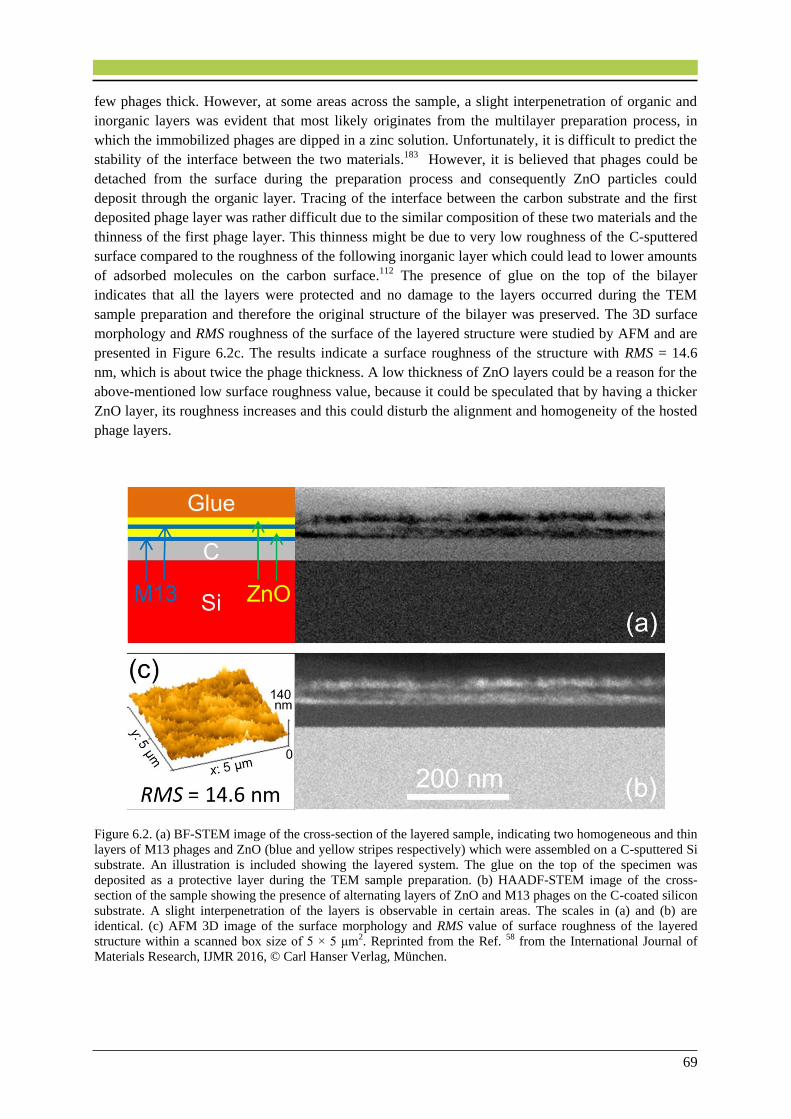
69
few phages thick. However, at some areas across the sample, a slight interpenetration of organic and
inorganic layers was evident that most likely originates from the multilayer preparation process, in
which the immobilized phages are dipped in a zinc solution. Unfortunately, it is difficult to predict the
stability of the interface between the two materials.183 However, it is believed that phages could be
detached from the surface during the preparation process and consequently ZnO particles could
deposit through the organic layer. Tracing of the interface between the carbon substrate and the first
deposited phage layer was rather difficult due to the similar composition of these two materials and the
thinness of the first phage layer. This thinness might be due to very low roughness of the C-sputtered
surface compared to the roughness of the following inorganic layer which could lead to lower amounts
of adsorbed molecules on the carbon surface.112 The presence of glue on the top of the bilayer
indicates that all the layers were protected and no damage to the layers occurred during the TEM
sample preparation and therefore the original structure of the bilayer was preserved. The 3D surface
morphology and RMS roughness of the surface of the layered structure were studied by AFM and are
presented in Figure 6.2c. The results indicate a surface roughness of the structure with RMS = 14.6
nm, which is about twice the phage thickness. A low thickness of ZnO layers could be a reason for the
above-mentioned low surface roughness value, because it could be speculated that by having a thicker
ZnO layer, its roughness increases and this could disturb the alignment and homogeneity of the hosted
phage layers.
Figure 6.2. (a) BF-STEM image of the cross-section of the layered sample, indicating two homogeneous and thin
layers of M13 phages and ZnO (blue and yellow stripes respectively) which were assembled on a C-sputtered Si
substrate. An illustration is included showing the layered system. The glue on the top of the specimen was
deposited as a protective layer during the TEM sample preparation. (b) HAADF-STEM image of the cross-
section of the sample showing the presence of alternating layers of ZnO and M13 phages on the C-coated silicon
substrate. A slight interpenetration of the layers is observable in certain areas. The scales in (a) and (b) are
identical. (c) AFM 3D image of the surface morphology and RMS value of surface roughness of the layered
structure within a scanned box size of 5 × 5 μm2. Reprinted from the Ref. 58 from the International Journal of
Materials Research, IJMR 2016, © Carl Hanser Verlag, München.
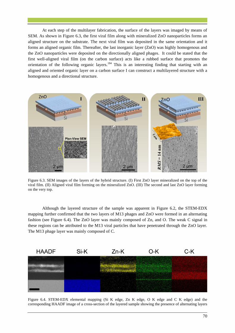
70
At each step of the multilayer fabrication, the surface of the layers was imaged by means of
SEM. As shown in Figure 6.3, the first viral film along with mineralized ZnO nanoparticles forms an
aligned structure on the substrate. The next viral film was deposited in the same orientation and it
forms an aligned organic film. Thereafter, the last inorganic layer (ZnO) was highly homogenous and
the ZnO nanoparticles were deposited on the directionally aligned phages. It could be stated that the
first well-aligned viral film (on the carbon surface) acts like a rubbed surface that promotes the
orientation of the following organic layers.184 This is an interesting finding that starting with an
aligned and oriented organic layer on a carbon surface I can construct a multilayered structure with a
homogenous and a directional structure.
Figure 6.3. SEM images of the layers of the hybrid structure. (I) First ZnO layer mineralized on the top of the
viral film. (II) Aligned viral film forming on the mineralized ZnO. (III) The second and last ZnO layer forming
on the very top.
Although the layered structure of the sample was apparent in Figure 6.2, the STEM-EDX
mapping further confirmed that the two layers of M13 phages and ZnO were formed in an alternating
fashion (see Figure 6.4). The ZnO layer was mainly composed of Zn, and O. The weak C signal in
these regions can be attributed to the M13 viral particles that have penetrated through the ZnO layer.
The M13 phage layer was mainly composed of C.
Figure 6.4. STEM-EDX elemental mapping (Si K edge, Zn K edge, O K edge and C K edge) and the
corresponding HAADF image of a cross-section of the layered sample showing the presence of alternating layers
71
of ZnO and M13 phages on the C-coated silicon substrate. The scale bar represents 50 nm. Reprinted from the
Ref. 58 from the International Journal of Materials Research, IJMR 2016, © Carl Hanser Verlag, München.
The Zn signal in the phage layer could be attributed to (i) the slight interpenetration of ZnO into
the M13 phage layer and (ii) to the vertical projection of the layers considering the cylindrical shape of
the phages with the mineralized ZnO nanoparticles. The cylindricality of phages results in a sinusoidal
shape of the phage layer surface and this can in turn lead to the presence of Zn signal in the organic
layers. Additionally, the carbon signal on the top of the structure shows the presence of the glue that
capped the specimen during the TEM sample preparation as a protective layer. The O signal at the top
of the silicon substrate and below the carbon coat layer can be attributed to the oxidation of the silicon
when it was exposed to air before carbon coating.185
6.5. Conclusions
As a part of the current thesis, I successfully assembled a phage-controlled nano-hybrid structure
on a carbon-coated silicon wafer using wild-type M13 phages and ZnO as the organic and the
inorganic layers, respectively. Double alternating layers were uniformly grown on a highly smooth C-
sputtered silicon wafer using the biomineralization process. In this project, the a-C surface was chosen
because M13 phages have shown in chapter 4 to have high affinity to form assembled and densely-
packed layers on a-C surfaces. In this chapter, it was confirmed that a-C surfaces are promising films
to host directionally oriented phages over long length scales. The structure, elemental composition,
and also the integrity of the alternating biologically-templated inorganic multilayers were
characterized by means of SEM and STEM imaging in conjunction with analytical techniques. A
homogeneous organic–inorganic hybrid structure without significant thickness fluctuations and with
limited interpenetration of the interfaces was achieved. The conditions of the multilayer assembly
process could result in a slight interpenetration of the adjacent organic and inorganic layers. Just as
important, the homogeneity of the templating layers profoundly affected the evenness of the following
layers and the roughness of the multilayered structure. This effect was reduced in our system by using
a thin carbon film as the substrate in order to obtain a smooth and homogeneous layer-by-layer
structure. This work provides information for the templating of organic–inorganic multilayers at the
nanoscale, which might have potential in the construction of novel multicomponent electronic devices.
Contributions to this chapter:
Pouya Moghimian, Stefan Kilper (MPI-IS) and Dirk Rothenstein (University of Stuttgart)
designed the study. Pouya Moghimian and Vesna Srot (MPI-FKF) performed the research.
Sandra J. Facey (University of Stuttgart) prepared the phage solutions. Reinhart Völker (MPI-
IS) carried out the carbon film deposition. Mahdieh Aghamohammadi (MPI-FKF) did the
AFM work. Bernhard Hauer (University of Stuttgart), Joachim Bill (University of Stuttgart)
and Peter A. van Aken (MPI-FKF) jointly supervised this work. The published article (Ref.
58) was written by Pouya Moghimian.
72
7. Chapter 7. Conclusions and Future
Directions
7.1. Concluding Remarks
This thesis focuses on (i) the structure and the stability of M13 phages as liquid crystal model
systems in different organic solvents, (ii) the fundamental understanding of the behavior and self-
assembly of liquid crystals on structured and unstructured surfaces, (iii) the biomineralization process
of inorganic materials by M13 phages in solution, and (iv) the bottom-up synthesis of novel hybrid
organic–inorganic multilayered structures based on our understanding of the liquid crystal phases, the
materials interaction (substrate-molecule specific interactions and molecules-inorganic interactions),
and the biomineralization process.
In chapter 1, the objectives and the main challenges of this research thesis are introduced.
M13 phages were introduced as our liquid crystal model system in this thesis. The liquid crystal (LC)
fundamentals and different LC phases as well as the self-assembly behavior in solutions were
discussed in detail. Furthermore, possible defects that can occur in the liquid crystalline structures
were classified. Biomineralization was discussed as a tool for the construction of organic–inorganic
hybrid structures.
In chapter 2, all characterization and experimental techniques that were used in this research
thesis, are explained. SEM, TEM and AFM principles were described and they were shown to be
prominent tools for the characterization (imaging and analytics) of our organic and inorganic systems.
Contact goniometry method was described as a tool for the investigation of the hydrophobicity of solid
surfaces. Our in-house-built apparatus (i.e. convective assembly) was introduced as a promising tool to
assemble layers of rod-like phages from a pulling solution in a directional fashion. The design and the
setup of this apparatus were done as a part of this thesis project.
In chapter 3, I have presented the results on the structural integrity and stability of
filamentous M13 phages when exposed to different organic media, as the first step, to understand the
structural behavior of these macromolecules. Yielding conditions to maintain the structural integrity of
viruses leads to an increased understanding of the factors that disrupt their structure. It has been shown
that phages would denature in polar organic solvents as compared to nonpolar solvents. The exposure
of M13 phages to apolar solvents had no effect on the structure of the phages for up to 8 h. In contrast,
phages showed ~8-fold contraction into rod-like I-forms and to flattened spheroids with ~12 nm
diameter upon exposure to polar organic solvents. It was concluded that the fragmentation and as a
consequence denaturation of phages can be understood by considering three role-playing factors:
Solvent hydrogen-binding capacity, hydrophobicity and water miscibility. Hexane, that is a non-polar
hydrophobic organic solvent, was shown to be incapable to compete for the hydrogen bonds between
the phage coat proteins and therefore it was not able to deform the native structure of the phages. In
contrast, polar solvents employed in our study (chloroform, THF and toluene) were able to break the
hydrogen bonding and the hydrophobic interactions between the phage coat proteins. Higher polarities
of the solvents used in our experiments, had an influence on breaking the inter-coat protein forces and
even weakening the van der Waals interactions between the ssDNA and the coat proteins. The latter
can lead to a collapse of the viral structure. I used this knowledge to find appropriate conditions in
which phage assemblies can keep their primary structure upon exposure to solvents for long periods of

73
time (up to 8 hours). This can be used in the developing topic of research that is the control of
macromolecular assemblies with hierarchical frameworks.
In chapter 4, I have reported the adsorption and self-assembly of macromolecules (M13
phages) on flat (i.e. unstructured) surfaces. The role of different substrates (SiO2 and a-C) was also
investigated and reported in terms of surface chemistry and competitive electrostatic interactions. This
was a necessity in the growing field of self-assembly because I have shown that, not only the
conditions of the bulk sample control the liquid crystalline phase, but also the chemistry and surface
properties of the adsorbent have an influence on the average orientation of the molecules. Obtaining
directionally organized layers of M13 phages was a challenge due to their extremely low thickness,
flexibility, and high affinity for bundle formation. In order to investigate the role of the surface on the
adsorption of phages, the self-assembly was studied in two liquid crystalline regions: in the extreme
isotropic region and above the nematic threshold. Our results revealed that the low concentration of
M13 phage solution (1.4 × 10¹³ pfu/mL) leads to the disordered phase of viral particles on the SiO2
surface. Phage bundles were formed on the SiO2 surface, which resulted in a decrease of the apparent
concentration of filamentous phages. Therefore, the trend of the system was toward the formation of
an isotropic phage distribution. However, when the same solution was deposited on a-C film, the
molecules showed a degree of alignment. By increasing the concentration of the primary phage
solution above the nematic threshold (3.5 × 10¹⁴ pfu/mL), phages showed a high degree of alignment
on the a-C film. On the SiO2 film, besides having a high degree of orientation, molecules showed
branched arrays on the surface. This can be attributed to the fact that SiO2 has a smooth and
hydrophilic surface, whereas, a-C has a hydrophobic surface and therefore causes weak interactions
between the phages and the solid surface. This is believed to allow for the higher mobility of phages
on a-C surface and further directional stacking of the 2D viral film. Our work demonstrated that under
specific experimental conditions, the a-C film is a promising host for highly oriented layers of M13
phages compared with SiO2. The M13 phage particles were found to have a high affinity for
incorporation into a densely assembled pattern on a-C films. These results suggest a versatile approach
that can be used to influence the mineralization of a variety of smooth and homogeneous inorganic
nanostructure layers and therefore open up exciting opportunities for the fabrication of organic–
inorganic systems with nanoscale precision. I used these results later on (in chapter 6) and constructed
multilayers of organic–inorganic materials, which contain alternating virus-templated layers.
These results opened up a new route for us to enhance the functional properties of inorganic
materials, by using a self-assembled layer of densely-packed organic molecules to spatially arrange
inorganic nanoparticles. For instance, I am using our knowledge on the self-assembly process to
spatially arrange magnetic iron oxide nanoparticles on M13 phage templates in order to enhance the
magnetic collective properties. To this end, phages are now being assembled on C-sputtered Si wafers
at centimeter scales.
In chapter 5, although I have investigated the self-assembly of M13 macromolecules on flat
surfaces in chapter 4, it is well known that an ordered medium of liquid crystals often possesses a
variety of defects and deformations, at which the director n(r) of the liquid crystal undergoes an abrupt
change compared to the vicinity of the defect. Experimental research on these effects had been
remained challenging and been barely performed on confined rod-like colloidal particles at complex
surfaces. Therefore, I studied the local deformation of rod-like M13 phage particles resulting from
confinement in an irregular stranded web of thin a-C film in order to investigate the so-called 2D wall-
anchoring. In this thesis chapter, I shifted the focus from evaporative self-organization on rationally
designed surfaces to that on a complex surface. Here I deposited phages onto carbon web films with
asymmetric shapes to study the effect of irregular spatial confinement on long semi-flexible M13
phages and their bending behavior. I showed that on unstructured and wide surface areas far from the

74
a-C surface edges, the phages exhibited random orientations when dispersed with a low concentration
(1.0 × 10¹³ pfu/mL) in the isotropic phase. However, the orientation of M13 phages in two-
dimensional nematic films was controlled by the orientation and curvature of the substrate edges. It
was shown that on a single and narrow carbon strand (the straight leg of a Y junction) the mean
molecular alignment can be described by a unit vector field, referred to as the director, which is
oriented parallel to the axis of the strand. Whereas, a significant orientational evolution occurred in the
intersections where the carbon strands meet. Here the M13 phages adopted a configuration that
matched the confining boundary conditions in order to minimize the total free energy. In particular, the
edges of the substrate determine the orientation of nearby phages. This orientational order is further
induced to the neighboring molecules via intermolecular forces leading to the formation of oriented
bundles of phages. Hence, close to the curved edges of the surface the phages tend to align parallel to
the edges due to effective entropic forces and attractive van der Waals forces acting between them and
the collars along the edges of the carbon surface. It should be noted that the drying process of the
phages on the substrate can only modify the strength of the total effective forces acting on the
orientational order of phages due to the increase of phage concentration at the contact lines with the
solid surface. In other words, phages close to the surface edges orient and align such that their main
axis directions become parallel to the periphery of the surface boundary. An annulus sector was
superimposed on these oriented phage bundles that allowed us to derive analytic expressions for the
bending energy of such oriented bundles. The defect, beyond which the molecules are geometrically
frustrated, is located at the point at which the two annulus sectors meet. Our theoretical approach
provides an explanation for the different number of phages orienting close to the surface edges with
different local curvatures. By comparing the self-assembly on differently shaped carbon substrates, it
was demonstrated that the alignment of the phages can be controlled by choosing appropriate substrate
shapes. Properties of the system are characterized by the free energy which includes both energetic
and entropic contributions. The competition of these contributions determines the resulting structures.
Understanding the orientational behavior of phages on complex geometries of carbon web films can
offer the active use of topological defects in controlling of liquid crystal flow, because the presence of
topological defects strongly affects the flow of liquid crystals which elastically interact with surfaces.
Besides, our results could find application in the liquid crystal technology (e.g. memory
effects) in topological manifolds which have interconnected porous media, similar to our carbon web
films. This offers a convenient means to fabricate designed structures of orientationally ordered M13
phages. The understanding of such systems opens up new possibilities for defect engineering of liquid
crystals which can be beneficial for the applications of liquid crystals in the presence of surface
microscopic pores and irregularities.
In chapter 6, after detailed investigations on the adsorption and self-assembly behavior of M13
molecules on different surface structures in chapters 4 and 5, I employed phages as a soft scaffold for
the layer-by-layer fabrication of hybrid organic–inorganic structures. The use of M13 phages for such
multilayer design has not been done before. Bio-inspired fabrication of organic–inorganic nano-hybrid
structures, where inorganic nanomaterials are templated by the organic component, are of high interest
due to the broad range of applications of these structures. In this chapter, I used our designed in-house-
built convective assembly apparatus to assemble densely-packed and highly-oriented phage layers
(from a 3.5 × 10¹⁴ pfu/mL viral solution) on C-coated Si wafers. Because, a-C surface showed to be a
promising host for aligned phages (as discussed in chapter 4). In our laboratory, I successfully
assembled a phage-controlled nano-hybrid structure on a C-coated Si wafer using wild-type M13
phages and ZnO as the organic and the inorganic layers, respectively. Double alternating ZnO layers
of about 20 nm were grown on directionally assembled phage templates via biomineralization process
from a mineralization solution. The microstructure, elemental composition, and also the integrity of
75
the alternating biologically-templated inorganic multilayers were characterized using SEM, TEM and
AFM. A homogeneous organic–inorganic hybrid structure without significant thickness fluctuations
and with limited interpenetration of the interfaces was achieved. It was shown that the well-aligned
viral films might act like a rubbed surface that promotes the alignment on the following layers. The
RMS roughness of the resulting bilayered structure was measured to be ~14 nm which is only double
of a single phage thickness. Our work provides information for the templating of organic–inorganic
multilayers at the nanoscale, which might have potential in the construction of novel multicomponents
with controlled organic to inorganic ratios.
Currently, I am working on the construction of a micrometer-scale multilayered structure which
consists of 10 alternating organic (M13 phage) and inorganic (ZnO) layers with an adjusted thickness
in order to enhance the mechanical properties of such multilayers.
All in all, our results give a comprehensive insight into 2D molecular self-assembly which can be
used in the generation of alternating multilayered systems with nanostructured bio-templated inorganic
materials that can be used as a constituent of electronic devices, such as transistors.
76
DECLARATION
Hereby I declare that this thesis titled, “Liquid Crystal Self-Assembly and Organic–Inorganic Hybrid
Material Design” has been independently carried out by me at the Stuttgart Center for Electron
Microscopy (StEM), Max Planck Institute for Solid State Research in partial fulfillment of the
requirements for the degree of Doctor of Philosophy (Dr. rer. nat.) in Materials Science from
Technical University of Darmstadt (TUD). I certify that the work presented in this thesis is, to the best
of my knowledge and belief, original and contains no material previously published or written by
another person, except where due reference and permission is made.
Stuttgart
23.01.2017 Pouya Moghimian

77
REFERENCES 1. Laskin, A. I.; Gadd, G. M.; Sarialani, S. Advances in Applied Microbiology; Elsevier Science
Serials2012.
2. Chung, W. J.; Sena, M.; Merzlyak, A.; Lee, S. W. Phages as Tools for Functional
Nanomaterials Development. In Comprehensive Biomaterials, Editor-in-Chief: Paul, D., Ed.;
Elsevier: Oxford, 2011, pp 95-111.
3. Monk, A. B.; Rees, C. D.; Barrow, P.; Hagens, S.; Harper, D. R. Bacteriophage applications:
where are we now? Letters in Applied Microbiology 2010, 51 (4), 363-369.
4. Loset, G. A.; Sandlie, I. Next generation phage display by use of pVII and pIX as display
scaffolds. Methods 2012, 58 (1), 40-46.
5. Fauquet, C. M.; Mayo, M. A.; Maniloff, J.; Desselberger, U.; Ball, L. A. Virus Taxonomy:
VIIIth Report of the International Committee on Taxonomy of Viruses; Elsevier Science2005.
6. Hyman, P.; Abedon, S. T. Bacteriophage (overview). In Encyclopedia of Microbiology (Third
Edition), Editor-in-Chief: Moselio, S., Ed.; Academic Press: Oxford, 2009, pp 322-338.
7. Tey, B. T.; Ooi, S. T.; Yong, K. C.; Ng, M. Y. T.; Ling, T. C.; Tan, W. S. Production of fusion
m13 phage bearing the di-sulphide constrained peptide sequence (C-WSFFSNI-C) that interacts with
hepatitis B core antigen. Afr. J. Biotechnol. 2009, 8 (2), 268-273.
8. Rakonjac, J. Filamentous Bacteriophages: Biology and Applications. In eLS; John Wiley &
Sons, Ltd, 2001.
9. Mohan, K.; Weiss, G. A. Chemically Modifying Viruses for Diverse Applications. ACS
Chemical Biology 2016.
10. Purdy, K. R.; Fraden, S. Isotropic-cholesteric phase transition of filamentous virus
suspensions as a function of rod length and charge. Physical Review E 2004, 70 (6), 061703.
11. Khalil, A. S.; Ferrer, J. M.; Brau, R. R.; Kottmann, S. T.; Noren, C. J.; Lang, M. J.; Belcher,
A. M. Single M13 bacteriophage tethering and stretching. Proceedings of the National Academy of
Sciences 2007, 104 (12), 4892-4897.
12. Moghimian, P.; Harnau, L.; Srot, V.; de la Pena, F.; Farahmand Bafi, N.; Facey, S. J.; van
Aken, P. A. Controlled self-assembly of biomolecular rods on structured substrates. Soft Matter 2016,
12 (13), 3177-83.
13. Mao, C.; Wang, F.; Cao, B. Controlling Nanostructures of Mesoporous Silica Fibers by
Supramolecular Assembly of Genetically Modifiable Bacteriophages. Angewandte Chemie 2012, 124
(26), 6517-6521.
14. Chung, W. J.; Oh, J. W.; Kwak, K.; Lee, B. Y.; Meyer, J.; Wang, E.; Hexemer, A.; Lee, S. W.
Biomimetic self-templating supramolecular structures. Nature 2011, 478 (7369), 364-368.
15. Stopar, D.; Spruijt, R. B.; Wolfs, C.; Hemminga, M. A. Mimicking initial interactions of
bacteriophage M13 coat protein disassembly in model membrane systems. Biochemistry 1998, 37
(28), 10181-10187.
16. Jończyk, E.; Kłak, M.; Międzybrodzki, R.; Górski, A. The influence of external factors on
bacteriophages—review. Folia Microbiologica 2011, 56 (3), 191-200.
17. Yoo, P. J.; Nam, K. T.; Qi, J. F.; Lee, S. K.; Park, J.; Belcher, A. M.; Hammond, P. T.
Spontaneous assembly of viruses on multilayered polymer surfaces. Nat. Mater. 2006, 5 (3), 234-240.
18. Zaman, M. S.; Moon, C. H.; Bozhilov, K. N.; Haberer, E. D. Phage-directed synthesis of
copper sulfide: Structural and optical characterization. Nanotechnology 2013, 24 (32).
19. Sidhu, S. S. Engineering M13 for phage display. Biomolecular Engineering 2001, 18 (2), 57-
63.
20. Hess, G. T.; Guimaraes, C. P.; Spooner, E.; Ploegh, H. L.; Belcher, A. M. Orthogonal
Labeling of M13 Minor Capsid Proteins with DNA to Self-Assemble End-to-End Multiphage
Structures. ACS Synthetic Biology 2013.
21. Kierny, M. R.; Cunningham, T. D.; Kay, B. K. Detection of biomarkers using recombinant
antibodies coupled to nanostructured platforms. Nano Reviews 2012, 3, 10.3402/nano.v3i0.17240.
22. Johnson, I. D.; Hudson, B. S. Environmental modulation of M13 coat protein tryptophan
fluorescence dynamics. Biochemistry 1989, 28 (15), 6392-6400.
23. Salivar, W. O.; Tzagoloff, H.; Pratt, D. Some Physical-chemical and biological properties of
rod-shaped coliphage M13. Virology 1964, 24 (3), 359-371.
24. Nasir, S. F.; Jaworski, J. Assessing the stability of assembled filamentous phage coat protein
P8. Supramolecular Chemistry 2014, 26 (5/6), 329-337.

78
25. Collings, P. J.; Hird, M. Introduction to Liquid Crystals: Chemistry and Physics; CRC
Press1997.
26. Collings, P. J. Liquid Crystals: Nature's Delicate Phase of Matter; Princeton University
Press2002.
27. Khoo, I. C. Liquid Crystals; Wiley2007.
28. Dierking, I. Textures of Liquid Crystals; Wiley2006.
29. Singh, S.; Dunmur, D. A. Liquid Crystals: Fundamentals; World Scientific2002.
30. Peelle, B. R.; Krauland, E. M.; Wittrup, K. D.; Belcher, A. M. Design criteria for engineering
inorganic material-specific peptides. Langmuir 2005, 21 (15), 6929-6933.
31. Sawada, T.; Serizawa, T. Immobilization of highly oriented filamentous viruses onto polymer
substrates. J. Mat. Chem. B 2013, 1 (2), 149-152.
32. Dogic, Z.; Fraden, S. Cholesteric Phase in Virus Suspensions. Langmuir 2000, 16 (20), 7820-
7824.
33. Jeon, D.-Y.; Hwang, K. H.; Park, S.-J.; Kim, Y.-J.; Joo, M.-K.; Ahn, S.-E.; Kim, G.-T.; Nam,
C.-H. Controlled surface adsorption of fd filamentous phage by tuning of the pH and the
functionalization of the surface. Journal of Applied Physics 2011, 109 (6), 064701-6.
34. Lee, S.-W.; Wood, B. M.; Belcher, A. M. Chiral Smectic C Structures of Virus-Based Films†.
Langmuir 2002, 19 (5), 1592-1598.
35. Yang, S. H.; Chung, W. J.; McFarland, S.; Lee, S. W. Assembly of Bacteriophage into
Functional Materials. Chem. Rec. 2013, 13 (1), 43-59.
36. Klem, M. T.; Willits, D.; Solis, D. J.; Belcher, A. M.; Young, M.; Douglas, T. Bio-inspired
synthesis of protein-encapsulated CoPt nanoparticles. Adv. Funct. Mater. 2005, 15 (9), 1489-1494.
37. Henry, M.; Debarbieux, L. Tools from viruses: Bacteriophage successes and beyond. Virology
2012, 434 (2), 151-161.
38. Xu, H.; Cao, B. R.; George, A.; Mao, C. B. Self-Assembly and Mineralization of Genetically
Modifiable Biological Nanofibers Driven by beta-Structure Formation. Biomacromolecules 2011, 12
(6), 2193-2199.
39. Sawada, T.; Otsuka, H.; Yui, H.; Serizawa, T. Preparation and characterization of hybrid
hydrogels composed of physically cross-linked gelatin and liquid-crystalline filamentous viruses.
Polymer Bulletin 2015, 72 (6), 1487-1496.
40. Moghimian, P.; Srot, V.; Rothenstein, D.; Facey, S. J.; Harnau, L.; Hauer, B.; Bill, J.; van
Aken, P. A. Adsorption and Self-Assembly of M13 Phage into Directionally Organized Structures on
C and SiO2 Films. Langmuir 2014, 30 (38), 11428-11432.
41. Lee, S. W.; Mao, C. B.; Flynn, C. E.; Belcher, A. M. Ordering of quantum dots using
genetically engineered viruses. Science 2002, 296 (5569), 892-895.
42. Sotiropoulou, S.; Sierra-Sastre, Y.; Mark, S. S.; Batt, C. A. Biotemplated Nanostructured
Materials†. Chemistry of Materials 2008, 20 (3), 821-834.
43. He, T.; Abbineni, G.; Cao, B.; Mao, C. Nanofibrous Bio-inorganic Hybrid Structures Formed
Through Self-Assembly and Oriented Mineralization of Genetically Engineered Phage Nanofibers.
Small 2010, 6 (20), 2230-2235.
44. Pichon, B. P.; Demortière, A.; Pauly, M.; Mougin, K.; Derory, A.; Bégin-Colin, S. 2D
Assembling of Magnetic Iron Oxide Nanoparticles Promoted by SAMs Used as Well-Addressed
Surfaces. The Journal of Physical Chemistry C 2010, 114 (19), 9041-9048.
45. Kleman, M.; Lavrentovich, O. D. Topological point defects in nematic liquid crystals.
Philosophical Magazine 2006, 86 (25-26), 4117-4137.
46. Whaley, S. R.; English, D. S.; Hu, E. L.; Barbara, P. F.; Belcher, A. M. Selection of peptides
with semiconductor binding specificity for directed nanocrystal assembly. Nature 2000, 405 (6787),
665-668.
47. Shen, L.; Bao, N.; Zhou, Z.; Prevelige, P. E.; Gupta, A. Materials design using genetically
engineered proteins. Journal of Materials Chemistry 2011, 21 (47), 18868-18876.
48. Lee, S.-Y.; Lim, J.-S.; Harris, M. T. Synthesis and application of virus-based hybrid
nanomaterials. Biotechnology and Bioengineering 2012, 109 (1), 16-30.
49. Kim, J.; Rheem, Y.; Yoo, B.; Chong, Y.; Bozhilov, K. N.; Kim, D.; Sadowsky, M. J.; Hur, H.-
G.; Myung, N. V. Peptide-mediated shape- and size-tunable synthesis of gold nanostructures. Acta
Biomaterialia 2010, 6 (7), 2681-2689.
79
50. Soto, C. M.; Ratna, B. R. Virus hybrids as nanomaterials for biotechnology. Curr. Opin.
Biotechnol. 2010, 21 (4), 426-438.
51. Nam, K. T.; Kim, D. W.; Yoo, P. J.; Chiang, C. Y.; Meethong, N.; Hammond, P. T.; Chiang,
Y. M.; Belcher, A. M. Virus-enabled synthesis and assembly of nanowires for lithium ion battery
electrodes. Science 2006, 312 (5775), 885-888.
52. Lee, Y. J.; Yi, H.; Kim, W.-J.; Kang, K.; Yun, D. S.; Strano, M. S.; Ceder, G.; Belcher, A. M.
Fabricating Genetically Engineered High-Power Lithium-Ion Batteries Using Multiple Virus Genes.
Science 2009, 324 (5930), 1051-1055.
53. Huang, Y.; Chiang, C.-Y.; Lee, S. K.; Gao, Y.; Hu, E. L.; Yoreo, J. D.; Belcher, A. M.
Programmable Assembly of Nanoarchitectures Using Genetically Engineered Viruses. Nano Lett.
2005, 5 (7), 1429-1434.
54. Courchesne, N.-M. D.; Klug, M. T.; Chen, P.-Y.; Kooi, S. E.; Yun, D. S.; Hong, N.; Fang, N.
X.; Belcher, A. M.; Hammond, P. T. Assembly of a Bacteriophage-Based Template for the
Organization of Materials into Nanoporous Networks. Adv. Mater. 2014, n/a-n/a.
55. Jeong, C. K.; Kim, I.; Park, K.-I.; Oh, M. H.; Paik, H.; Hwang, G.-T.; No, K.; Nam, Y. S.;
Lee, K. J. Virus-Directed Design of a Flexible BaTiO3 Nanogenerator. ACS Nano 2013, 7 (12), 11016-
11025.
56. Chen, P.-Y.; Dang, X.; Klug, M. T.; Courchesne, N.-M. D.; Qi, J.; Hyder, M. N.; Belcher, A.
M.; Hammond, P. T. M13 Virus-Enabled Synthesis of Titanium Dioxide Nanowires for Tunable
Mesoporous Semiconducting Networks. Chemistry of Materials 2015, 27 (5), 1531-1540.
57. Atanasova, P.; Rothenstein, D.; Schneider, J. J.; Hoffmann, R. C.; Dilfer, S.; Eiben, S.; Wege,
C.; Jeske, H.; Bill, J. Virus-Templated Synthesis of ZnO Nanostructures and Formation of Field-Effect
Transistors. Adv. Mater. 2011, 23 (42), 4918-4922.
58. Moghimian, P.; Kilper, S.; Srot, V.; Rothenstein, D.; Facey, S. J.; Hauer, B.; Bill, J.; van
Aken, P. A. Phage-assisted assembly of organic–inorganic hybrid bilayers. International Journal of
Materials Research 2016, 107 (4), 295-299.
59. Janairo Jose Isagani, B.; Co, F.; Carandang Jose, S.; Amalin Divina, M. Sequence-dependent
cluster analysis of biomineralization peptides. In Zeitschrift für Naturforschung C, 2015; Vol. 70, p
191.
60. Masica, D. L.; Schrier, S. B.; Specht, E. A.; Gray, J. J. De Novo Design of Peptide−Calcite
Biomineralization Systems. Journal of the American Chemical Society 2010, 132 (35), 12252-12262.
61. Patwardhan, S. V.; Patwardhan, G.; Perry, C. C. Interactions of biomolecules with inorganic
materials: principles, applications and future prospects. Journal of Materials Chemistry 2007, 17 (28),
2875-2884.
62. Berti, L.; Burley, G. A. Nucleic acid and nucleotide-mediated synthesis of inorganic
nanoparticles. Nat Nano 2008, 3 (2), 81-87.
63. Balci, S.; Bittner, A. M.; Schirra, M.; Thonke, K.; Sauer, R.; Hahn, K.; Kadri, A.; Wege, C.;
Jeske, H.; Kern, K. Catalytic coating of virus particles with zinc oxide. Electrochimica Acta 2009, 54
(22), 5149-5154.
64. Gerstel, P.; Hoffmann, R. C.; Lipowsky, P.; Jeurgens, L. P. H.; Bill, J.; Aldinger, F.
Mineralization from Aqueous Solutions of Zinc Salts Directed by Amino Acids and Peptides.
Chemistry of Materials 2006, 18 (1), 179-186.
65. Tomczak, M. M.; Gupta, M. K.; Drummy, L. F.; Rozenzhak, S. M.; Naik, R. R.
Morphological control and assembly of zinc oxide using a biotemplate. Acta Biomaterialia 2009, 5
(3), 876-882.
66. Egerton, R. F. Physical Principles of Electron Microscopy: An Introduction to TEM, SEM,
and AEM; Springer2005.
67. Flegler, S. L.; Heckman, J. W.; Klomparens, K. L. Scanning and Transmission Electron
Microscopy: An Introduction; Oxford University Press1993.
68. Williams, D. B.; Carter, C. B. Transmission Electron Microscopy: A Textbook for Materials
Science; Springer London, Limited2009.
69. Reimer, L. Scanning Electron Microscopy: Physics of Image Formation and Microanalysis;
Springer1998.
70. Lobocka, M.; Szybalski, W. T. Bacteriophages; Elsevier Science2012.
71. Richards, R.; Owen, G. R.; Ap Gwynn, I. Low voltage backscattered electron imaging (< 5
kV) using field emission scanning electron microscopy. Scanning Microsc 1999, 13 (1), 55-60.
80
72. Egerton, R. F.; Li, P.; Malac, M. Radiation damage in the TEM and SEM. Micron 2004, 35
(6), 399-409.
73. Goodhew, P. J.; Humphreys, J.; Beanland, R. Electron Microscopy and Analysis, Third
Edition; Taylor & Francis2000.
74. Mullejans, H.; Bruley, J. Electron energy-loss spectroscopy (EELS); comparison with x-ray
analysis. Journal De Physique 1993, 3 (7 pt 3), 2083-2092.
75. Wang, Y.; Baiutti, F.; Gregori, G.; Cristiani, G.; Salzberger, U.; Logvenov, G.; Maier, J.; van
Aken, P. A. Atomic-Scale Quantitative Analysis of Lattice Distortions at Interfaces of Two-
Dimensionally Sr-Doped La(2)CuO(4) Superlattices. ACS Applied Materials & Interfaces 2016, 8
(10), 6763-6769.
76. Hayat, M. Basic Techniques For Transmission Electron Microscopy; Elsevier Science1985.
77. Slocik, J. M.; Stone, M. O.; Naik, R. R. Synthesis of gold nanoparticles using multifunctional
peptides. Small 2005, 1 (11), 1048-1052.
78. Dang, X.; Yi, H.; Ham, M.-H.; Qi, J.; Yun, D. S.; Ladewski, R.; Strano, M. S.; Hammond, P.
T.; Belcher, A. M. Virus-templated self-assembled single-walled carbon nanotubes for highly efficient
electron collection in photovoltaic devices. Nat Nano 2011, 6 (6), 377-384.
79. Nam, Y. S.; Magyar, A. P.; Lee, D.; Kim, J. W.; Yun, D. S.; Park, H.; Pollom, T. S.; Weitz, D.
A.; Belcher, A. M. Biologically templated photocatalytic nanostructures for sustained light-driven
water oxidation. Nat. Nanotechnol. 2010, 5 (5), 340-344.
80. Cao, B. R.; Xu, H.; Mao, C. B. Transmission Electron Microscopy as a Tool to Image
Bioinorganic Nanohybrids: The Case of Phage-Gold Nanocomposites. Microsc. Res. Tech. 2011, 74
(7), 627-635.
81. Özdöl, V. B.; Srot, V.; van Aken, P. A. Sample Preparation Techniques for Transmission
Electron Microscopy. In Handbook of Nanoscopy; Wiley-VCH Verlag GmbH & Co. KGaA, 2012, pp
473-498.
82. Srot, V.; Bussmann, B.; Salzberger, U.; Koch, C. T.; van Aken, P. A. Linking Microstructure
and Nanochemistry in Human Dental Tissues. Microscopy and Microanalysis 2012, 18 (03), 509-523.
83. Voigtlaender, B. Scanning Probe Microscopy: Atomic Force Microscopy and Scanning
Tunneling Microscopy; Springer Berlin Heidelberg2015.
84. Förch, R.; Schönherr, H.; Jenkins, A. T. A. Surface Design: Applications in Bioscience and
Nanotechnology; Wiley2009.
85. Pazokian, H.; Jelvani, S.; Mollabashi, M.; Barzin, J.; Azizabadi Farahani, G. ArF laser surface
modification of polyethersulfone film: Effect of laser fluence in improving surface biocompatibility.
Applied Surface Science 2011, 257 (14), 6186-6190.
86. (http://www.biosci.missouri.edu/smithgp/PhageDisplayWebsite/PhageDisplayWebsiteIndex)
(AbsorptionSpectrum.doc 12/29/1999).
87. Lin, Z. Evaporative self-assembly of ordered complex structures; World Scientific Publishing
Company, Incorporated2012.
88. Hernando-Perez, M.; Pascual, E.; Aznar, M.; Ionel, A.; Caston, J. R.; Luque, A.; Carrascosa,
J. L.; Reguera, D.; de Pablo, P. J. The interplay between mechanics and stability of viral cages.
Nanoscale 2014, 6 (5), 2702-2709.
89. Moghimian, P.; Srot, V.; Pichon, B. P.; Facey, S. J.; van Aken, P. A. Stability of M13 Phage
in Organic Solvents. Journal of Biomaterials and Nanobiotechnology 2016, 7 (2), 72-77.
90. Mattos, C.; Ringe, D. Proteins in organic solvents. Current Opinion in Structural Biology
2001, 11 (6), 761-764.
91. Lau, F. W.; Bowie, J. U. A Method for Assessing the Stability of a Membrane Protein.
Biochemistry 1997, 36 (19), 5884-5892.
92. Amako, K.; Yasunaka, K. Ether induced morphological alteration of Pf-1 filamentous phage.
Nature 1977, 267 (5614), 862-863.
93. Olofsson, L.; Ankarloo, J.; Andersson, P. O.; Nicholls, I. A. Filamentous bacteriophage
stability in non-aqueous media. Chemistry & Biology 2001, 8 (7), 661-671.
94. Mao, C.; Liu, A.; Cao, B. Virus-Based Chemical and Biological Sensing. Angewandte Chemie
International Edition 2009, 48 (37), 6790-6810.
95. Lee, Y. M.; Kim, Y. H.; Lee, J. H.; Park, J. H.; Park, N.-G.; Choe, W.-S.; Ko, M. J.; Yoo, P. J.
Highly Interconnected Porous Electrodes for Dye-Sensitized Solar Cells Using Viruses as a Sacrificial
Template. Adv. Funct. Mater. 2011, 21 (6), 1160-1167.

81
96. Tsen, K. T.; Tsen, S.-W. D.; Fu, Q.; Lindsay, S. M.; Kibler, K.; Jacobs, B.; Wu, T. C.; Li, Z.;
Yan, H.; Cope, S.; Vaiana, S.; Kiang, J. G. In Photonic approach to the selective inactivation of
viruses with a near-infrared ultrashort pulsed laser, 2010, pp 75610W-75610W-10.
97. Zhong, C.; Duan, C.; Huang, F.; Wu, H.; Cao, Y. Materials and Devices toward Fully Solution
Processable Organic Light-Emitting Diodes. Chemistry of Materials 2011, 23 (3), 326-340.
98. Roberts, L. M.; Dunker, A. K. Structural changes accompanying chloroform-induced
contraction of the filamentous phage fd. Biochemistry 1993, 32 (39), 10479-10488.
99. Wigle, J. C.; Holwitt, E. A.; Noojin, G. D.; Estlack, L. E.; Sheldon, K. E.; Rockwell, B. A. In
No effect of femtosecond laser pulses on DNA, protein, M13, or E. coli, 2011, pp 789716-789716-9.
100. Martinek, K.; Mozhaev, V. V.; Smirnov, M. D.; Berezin, L. V. Reactivation of “irreversibly”
denaturated enzymes. Biotechnology and Bioengineering 1980, 22 (1), 247-251.
101. Lee, B. Y.; Zhang, J.; Zueger, C.; Chung, W.-J.; Yoo, S. Y.; Wang, E.; Meyer, J.; Ramesh, R.;
Lee, S.-W. Virus-based piezoelectric energy generation. Nat Nano 2012, 7 (6), 351-356.
102. Toulemon, D.; Pichon, B. P.; Cattoen, X.; Man, M. W. C.; Begin-Colin, S. 2D assembly of
non-interacting magnetic iron oxide nanoparticles via "click" chemistry. Chemical Communications
2011, 47 (43), 11954-11956.
103. Neltner, B.; Peddie, B.; Xu, A.; Doenlen, W.; Durand, K.; Yun, D. S.; Speakman, S.; Peterson,
A.; Belcher, A. Production of Hydrogen Using Nanocrystalline Protein-Templated Catalysts on M13
Phage. ACS Nano 2010, 4 (6), 3227-3235.
104. Cao, B.; Zhu, Y.; Wang, L.; Mao, C. Controlled Alignment of Filamentous Supramolecular
Assemblies of Biomolecules into Centimeter-Scale Highly Ordered Patterns by Using Nature-Inspired
Magnetic Guidance. Angewandte Chemie International Edition 2013, 52 (45), 11750-11754.
105. Whyburn, G. P.; Li, Y.; Huang, Y. Protein and protein assembly based material structures.
Journal of Materials Chemistry 2008, 18 (32), 3755-3762.
106. Wang, J.; Wang, L.; Li, X.; Mao, C. Virus activated artificial ECM induces the osteoblastic
differentiation of mesenchymal stem cells without osteogenic supplements. Sci. Rep. 2013, 3.
107. Zhu, H.; Cao, B.; Zhen, Z.; Laxmi, A. A.; Li, D.; Liu, S.; Mao, C. Controlled growth and
differentiation of MSCs on grooved films assembled from monodisperse biological nanofibers with
genetically tunable surface chemistries. Biomaterials 2011, 32 (21), 4744-4752.
108. Kuncicky, D. M.; Naik, R. R.; Velev, O. D. Rapid deposition and long-range alignment of
nanocoatings and arrays of electrically conductive wires from tobacco mosaic virus. Small 2006, 2
(12), 1462-1466.
109. Vinnichenko, M.; Gago, R.; Huang, N.; Leng, Y. X.; Sun, H.; Kreissig, U.; Kulish, M. P.;
Maitz, M. F. Spectroscopic ellipsometry investigation of amorphous carbon films with different sp3
content: relation with protein adsorption. Thin Solid Films 2004, 455–456 (0), 530-534.
110. Lee, Y. M.; Jung, B.; Kim, Y. H.; Park, A. R.; Han, S.; Choe, W.-S.; Yoo, P. J. Nanomesh-
Structured Ultrathin Membranes Harnessing the Unidirectional Alignment of Viruses on a Graphene-
Oxide Film. Adv. Mater. 2014, 26 (23), 3899-3904.
111. Ling, T. C.; Loong, C. M.; Tan, W. S.; Tey, B. T.; Abdullah, W. M. W.; Ariff, A. Purification
of filamentous bacteriophage M13 by expanded bed anion exchange chromatography. Journal of
Microbiology 2004, 42 (3), 228-232.
112. Merzlyak, A.; Lee, S. W. Phage as templates for hybrid materials and mediators for
nanomaterial synthesis. Curr. Opin. Chem. Biol. 2006, 10 (3), 246-252.
113. Zakharova, M. Y.; Kozyr, A. V.; Ignatova, A. N.; Vinnikov, I. A.; Sherriyakin, I. G.;
Kolesnikov, A. V. Purification of filamentous bacteriophage for phage display using size-exclusion
chromatography. Biotechniques 2005, 38 (2), 194-+.
114. Berlind, T.; Tengvall, P.; Hultman, L.; Arwin, H. Protein adsorption on thin films of carbon
and carbon nitride monitored with in situ ellipsometry. Acta Biomaterialia 2011, 7 (3), 1369-1378.
115. Masteika, V.; Kowal, J.; Braithwaite, N. S. J.; Rogers, T. A Review of Hydrophilic Silicon
Wafer Bonding. ECS Journal of Solid State Science and Technology 2014, 3 (4), Q42-Q54.
116. Gerba, C. P. Applied and Theoretical Aspects of Virus Adsorption to Surfaces. In Advances in
Applied Microbiology, Allen, I. L., Ed.; Academic Press, 1984; Vol. Volume 30, pp 133-168.
117. Takeda, S.; Fukawa, M.; Hayashi, Y.; Matsumoto, K. Surface OH group governing adsorption
properties of metal oxide films. Thin Solid Films 1999, 339 (1–2), 220-224.
118. Takeda, S.; Fukawa, M. Role of surface OH groups in surface chemical properties of metal
oxide films. Materials Science and Engineering: B 2005, 119 (3), 265-267.

82
119. Kayser, R. F.; Raveché, H. J. Bifurcation in Onsager's model of the isotropic-nematic
transition. Physical Review A 1978, 17 (6), 2067-2072.
120. Bolisetty, S.; Harnau, L.; Jung, J.-m.; Mezzenga, R. Gelation, Phase Behavior, and Dynamics
of β-Lactoglobulin Amyloid Fibrils at Varying Concentrations and Ionic Strengths.
Biomacromolecules 2012, 13 (10), 3241-3252.
121. Suib, S. L. New and Future Developments in Catalysis: Batteries, Hydrogen Storage and Fuel
Cells; Elsevier Science2013.
122. McCafferty, E.; Wightman, J. P. Determination of the concentration of surface hydroxyl
groups on metal oxide films by a quantitative XPS method. Surface and Interface Analysis 1998, 26
(8), 549-564.
123. Puddu, V.; Perry, C. C. Peptide Adsorption on Silica Nanoparticles: Evidence of Hydrophobic
Interactions. ACS Nano 2012, 6 (7), 6356-6363.
124. Scott, E. A.; Engineering, W. U. i. S. L. B. Improving Biocompatibility by Controlling Protein
Adsorption: Modification and Design of Biomaterials Using Poly(ethylene Glycol) Microgels and
Microspheres; Washington University in St. Louis2009.
125. Dinsmore, A.; Yodh, A.; Pine, D. Entropic control of particle motion using passive surface
microstructures. Nature 1996, 383 (6597), 239-242.
126. Ye, Y.-H.; Badilescu, S.; Truong, V.-V.; Rochon, P.; Natansohn, A. Self-assembly of colloidal
spheres on patterned substrates. Applied Physics Letters 2001, 79 (6), 872-874.
127. Lin, K.-h.; Crocker, J. C.; Prasad, V.; Schofield, A.; Weitz, D. A.; Lubensky, T. C.; Yodh, A.
G. Entropically Driven Colloidal Crystallization on Patterned Surfaces. Physical Review Letters 2000,
85 (8), 1770-1773.
128. Yin, Y.; Xia, Y. Growth of large colloidal crystals with their (100) planes orientated parallel to
the surfaces of supporting substrates. Adv. Mater. 2002, 14 (8), 605.
129. Bryk, P.; Roth, R.; Schoen, M.; Dietrich, S. Depletion potentials near geometrically structured
substrates. EPL (Europhysics Letters) 2003, 63 (2), 233.
130. Urrutia, I. Fluids confined in wedges and by edges: Virial series for the line-thermodynamic
properties of hard spheres. The Journal of Chemical Physics 2014, 141 (24), 244906.
131. Boda, D.; Chan, K.-Y.; Henderson, D.; Wasan, D. T.; Nikolov, A. D. Structure and Pressure
of a Hard Sphere Fluid in a Wedge-Shaped Cell or Meniscus. Langmuir 1999, 15 (13), 4311-4313.
132. Yu, Y.-X.; Wu, J. A modified fundamental measure theory for spherical particles in
microchannels. The Journal of Chemical Physics 2003, 119 (4), 2288-2295.
133. Merzlyak, A.; Indrakanti, S.; Lee, S.-W. Genetically Engineered Nanofiber-Like Viruses For
Tissue Regenerating Materials. Nano Lett. 2009, 9 (2), 846-852.
134. Viry, L.; Mercader, C.; Miaudet, P.; Zakri, C.; Derr, A.; Kuhn, A.; Maugey, M.; Poulin, P.
Nanotube fibers for electromechanical and shape memory actuators. Journal of Materials Chemistry
2010, 20 (17), 3487-3495.
135. Jiang, K.; Wang, J.; Li, Q.; Liu, L.; Liu, C.; Fan, S. Superaligned Carbon Nanotube Arrays,
Films, and Yarns: A Road to Applications. Adv. Mater. 2011, 23 (9), 1154-1161.
136. Kim, D.-H.; Lee, H.; Lee, Y. K.; Nam, J.-M.; Levchenko, A. Biomimetic Nanopatterns as
Enabling Tools for Analysis and Control of Live Cells. Adv. Mater. 2010, 22 (41), 4551-4566.
137. Yang, Z.; Chen, T.; He, R.; Guan, G.; Li, H.; Qiu, L.; Peng, H. Aligned Carbon Nanotube
Sheets for the Electrodes of Organic Solar Cells. Adv. Mater. 2011, 23 (45), 5436-5439.
138. Reddy, A. L. M.; Gowda, S. R.; Shaijumon, M. M.; Ajayan, P. M. Hybrid Nanostructures for
Energy Storage Applications. Adv. Mater. 2012, 24 (37), 5045-5064.
139. Han, J.; Craighead, H. G. Separation of Long DNA Molecules in a Microfabricated Entropic
Trap Array. Science 2000, 288 (5468), 1026-1029.
140. Masanori, U.; Tetsuya, H.; Yuzuru, T.; Yasuhiro, H.; Tomonari, D.; Yoshinobu, B. Curvature
Entropy Trapping of Long DNA under Hydrodynamic Flows in Microfluidic Devices. Japanese
Journal of Applied Physics 2004, 43 (4R), 1649.
141. Reccius, C. H.; Mannion, J. T.; Cross, J. D.; Craighead, H. G. Compression and Free
Expansion of Single DNA Molecules in Nanochannels. Physical Review Letters 2005, 95 (26),
268101.
142. Kheireddin, B. A.; Narayanunni, V.; Akbulut, M. Influence of Shearing Surface Topography
on Frictional Properties of ZnS Nanowire-Based Lubrication System across Ductile Surfaces. Journal
of Tribology 2012, 134 (2), 022001-022001.
83
143. Dammone, O. J.; Zacharoudiou, I.; Dullens, R. P. A.; Yeomans, J. M.; Lettinga, M. P.; Aarts,
D. G. A. L. Confinement Induced Splay-to-Bend Transition of Colloidal Rods. Physical Review
Letters 2012, 109 (10), 108303.
144. Tombolato, F.; Ferrarini, A.; Grelet, E. Chiral Nematic Phase of Suspensions of Rodlike
Viruses: Left-Handed Phase Helicity from a Right-Handed Molecular Helix. Physical Review Letters
2006, 96 (25), 258302.
145. Dugyala, V. R.; Daware, S. V.; Basavaraj, M. G. Shape anisotropic colloids: synthesis,
packing behavior, evaporation driven assembly, and their application in emulsion stabilization. Soft
Matter 2013, 9 (29), 6711-6725.
146. Byun, M.; Bowden, N. B.; Lin, Z. Hierarchically Organized Structures Engineered from
Controlled Evaporative Self-Assembly. Nano Lett. 2010, 10 (8), 3111-3117.
147. Lin, Y.; Su, Z.; Xiao, G.; Balizan, E.; Kaur, G.; Niu, Z.; Wang, Q. Self-Assembly of Virus
Particles on Flat Surfaces via Controlled Evaporation†. Langmuir 2010, 27 (4), 1398-1402.
148. Van Der Walt, S.; Schönberger, J. L.; Nunez-Iglesias, J.; Boulogne, F.; Warner, J. D.; Yager,
N.; Gouillart, E.; Yu, T. scikit-image: image processing in Python. PeerJ 2014, 2, e453.
149. De Gennes, P.; Prost, J. The physics of liquid crystals, 2nd edn Oxford University Press. New
York 1993.
150. Landau, L.; Lifshitz, E. Theory of Elasticity. Pergamon Press, Oxford, UK, 1986.
151. Landau, L.; Lifshitz, E. Statistical Physics, Part 1 (3rd edit.) Pergamon Press. Oxford, NY,
1980.
152. Rivetti, C.; Walker, C.; Bustamante, C. Polymer chain statistics and conformational analysis
of DNA molecules with bends or sections of different flexibility. Journal of Molecular Biology 1998,
280 (1), 41-59.
153. Rivetti, C.; Guthold, M.; Bustamante, C. Scanning Force Microscopy of DNA Deposited onto
Mica: EquilibrationversusKinetic Trapping Studied by Statistical Polymer Chain Analysis. Journal of
Molecular Biology 1996, 264 (5), 919-932.
154. Adamcik, J.; Mezzenga, R. Proteins Fibrils from a Polymer Physics Perspective.
Macromolecules 2011, 45 (3), 1137-1150.
155. Adamcik, J.; Jung, J.-M.; Flakowski, J.; De Los Rios, P.; Dietler, G.; Mezzenga, R.
Understanding amyloid aggregation by statistical analysis of atomic force microscopy images. Nat
Nano 2010, 5 (6), 423-428.
156. Rinke, G.; Rauschenbach, S.; Harnau, L.; Albarghash, A.; Pauly, M.; Kern, K. Active
Conformation Control of Unfolded Proteins by Hyperthermal Collision with a Metal Surface. Nano
Lett. 2014, 14 (10), 5609-5615.
157. Deng, Z.; Thontasen, N.; Malinowski, N.; Rinke, G.; Harnau, L.; Rauschenbach, S.; Kern, K.
A Close Look at Proteins: Submolecular Resolution of Two- and Three-Dimensionally Folded
Cytochrome c at Surfaces. Nano Lett. 2012, 12 (5), 2452-2458.
158. Abramowitz, M.; Stegun, I. A. Handbook of mathematical functions: with formulas, graphs,
and mathematical tables; Courier Dover Publications1972.
159. Malis, T.; Cheng, S. C.; Egerton, R. F. EELS log-ratio technique for specimen-thickness
measurement in the TEM. Journal of Electron Microscopy Technique 1988, 8 (2), 193-200.
160. Mitchell, D. R. G. Determination of mean free path for energy loss and surface oxide film
thickness using convergent beam electron diffraction and thickness mapping: a case study using Si and
P91 steel. Journal of Microscopy 2006, 224 (2), 187-196.
161. Harnau, L.; Penna, F.; Dietrich, S. Colloidal hard-rod fluids near geometrically structured
substrates. Physical Review E 2004, 70 (2), 021505.
162. Grelet, E. Hexagonal Order in Crystalline and Columnar Phases of Hard Rods. Physical
Review Letters 2008, 100 (16), 168301.
163. Jerome, B. Surface effects and anchoring in liquid crystals. Reports on Progress in Physics
1991, 54 (3), 391.
164. Soares e Silva, M.; Alvarado, J.; Nguyen, J.; Georgoulia, N.; Mulder, B. M.; Koenderink, G.
H. Self-organized patterns of actin filaments in cell-sized confinement. Soft Matter 2011, 7 (22),
10631-10641.
165. Zhang, S.; Kinloch, I. A.; Windle, A. H. Mesogenicity Drives Fractionation in Lyotropic
Aqueous Suspensions of Multiwall Carbon Nanotubes. Nano Lett. 2006, 6 (3), 568-572.
84
166. Chang, C.; Lu, L.; Liu, J.; Chen, W. Bending Deformation Mechanism and Defective
Properties of Liquid Crystalline Carbon Nanotubes in Evaporating Droplets. RSC Advances 2011, 1
(3), 468-473.
167. Zhang, S.; Li, Q.; Kinloch, I. A.; Windle, A. H. Ordering in a Droplet of an Aqueous
Suspension of Single-Wall Carbon Nanotubes on a Solid Substrate. Langmuir 2010, 26 (3), 2107-
2112.
168. Araki, T.; Serra, F.; Tanaka, H. Defect science and engineering of liquid crystals under
geometrical frustration. Soft Matter 2013, 9 (34), 8107-8120.
169. Belyaev, B. A.; Drokin, N. A.; Kumakhov, M. A.; Shabanov, V. F. Dielectric properties of
liquid crystals in polycapillary matrices. Physics of the Solid State 2010, 52 (6), 1315-1322.
170. Serra, F.; Eaton, S. M.; Cerbino, R.; Buscaglia, M.; Cerullo, G.; Osellame, R.; Bellini, T.
Nematic Liquid Crystals Embedded in Cubic Microlattices: Memory Effects and Bistable Pixels. Adv.
Funct. Mater. 2013, 23 (32), 3990-3994.
171. Park, S.; Yun, W. M.; Kim, L. H.; Park, S.; Kim, S. H.; Park, C. E. Inorganic/organic
multilayer passivation incorporating alternating stacks of organic/inorganic multilayers for long-term
air-stable organic light-emitting diodes. Organic Electronics 2013, 14 (12), 3385-3391.
172. Habib, M.; Watanabe, K.; Nagata, F. Bioinspiration and emerging actuator technologies. Artif
Life Robotics 2012, 17 (2), 191-196.
173. Cao, B.; Xu, H.; Mao, C. Phage as a Template to Grow Bone Mineral Nanocrystals. Methods
in molecular biology (Clifton, N.J.) 2014, 1108, 123-135.
174. Rothenstein, D.; Facey, S. J.; Ploss, M.; Hans, P.; Melcher, M.; Srot, V.; Van Aken, P. A.;
Hauer, B.; Bill, J. Mineralization of gold nanoparticles using tailored M13 phages. Bioinspired,
Biomimetic and Nanobiomaterials 2013, 2 (4, Themed Issue-Biomaterials Topic, MSE Conference,
Darmstadt, 25-27 September 2012-Part 2), 173-185.
175. Burghard, Z.; Zini, L.; Srot, V.; Bellina, P.; van Aken, P. A.; Bill, J. Toughening through
Nature-Adapted Nanoscale Design. Nano Lett. 2009, 9 (12), 4103-4108.
176. Takada, J.; Awaji, H.; Koshioka, M.; Nakajima, A.; Nevin, W. A. Organic–inorganic
multilayers: A new concept of optoelectronic material. Applied Physics Letters 1992, 61 (18), 2184-
2186.
177. Atanasova, P.; Weitz, R. T.; Gerstel, P.; Srot, V.; Kopold, P.; van Aken, P. A.; Burghard, M.;
Bill, J. DNA-templated synthesis of ZnO thin layers and nanowires. Nanotechnology 2009, 20 (36).
178. Lipowsky, P.; Hoffmann, R. C.; Welzel, U.; Bill, J.; Aldinger, F. Site-Selective Deposition of
Nanostructured ZnO Thin Films from Solutions Containing Polyvinylpyrrolidone. Adv. Funct. Mater.
2007, 17 (13), 2151-2159.
179. Mansoori, G. A.; George, T. F.; Assoufid, L.; Zhang, G. Molecular Building Blocks for
Nanotechnology: From Diamondoids to Nanoscale Materials and Applications; Springer New
York2007.
180. Cortes-Jimenez, S. Y. Site Specific Nanowire Growth. MATERIALS NNIN REU, 2006.
181. Peter, L.; Žaklina, B.; Lars, P. H. J.; Joachim, B.; Fritz, A. Laminates of zinc oxide and
poly(amino acid) layers with enhanced mechanical performance. Nanotechnology 2007, 18 (34),
345707.
182. Newman, J.; Swinney, H. L.; Day, L. A. Hydrodynamic properties and structure of fd virus.
Journal of Molecular Biology 1977, 116 (3), 593-603.
183. Niklasson, A. M. N.; Abrikosov, I. A.; Johansson, B. Interface mixing energy: A measure of
interface stability. Physical Review B 1998, 58 (7), 3613-3616.
184. Wang, X.; Miller, D. S.; Bukusoglu, E.; de Pablo, J. J.; Abbott, N. L. Topological defects in
liquid crystals as templates for molecular self-assembly. Nat Mater 2015, advance online publication.
185. Harsha, P. K. Principles of Vapor Deposition of Thin Films; Elsevier Science2005.