Liquid Cooling Package Plus - SysAdmin...
100
Rittal Liquid Cooling Package Plus Operating and Maintenance Instructions Rittal Liquid Cooling Package Plus Model No. SK 3301.480 (230 / 400 V version)
Transcript of Liquid Cooling Package Plus - SysAdmin...

RittalLiquid Cooling Package Plus
Operating and Maintenance Instructions
Rittal Liquid Cooling Package PlusModel No. SK 3301.480 (230 / 400 V version)

2 Operating and Maintenance Instructions
Rittal Liquid Cooling Package PlusForeword Dear Customer!
We would like to thank you for choosing our Rittal Liquid Cooling Package Plus (referred to hereafter as "Liquid Cooling Package Plus" or "LCP Plus").
Please take the time to read this documentation carefully.
Please pay particular attention to the safety instructions in the text and to Chapter 2, "Safety instructions".
This is the prerequisite for:- secure assembly of the Liquid Cooling Package Plus,
- safe handling and
- the most trouble-free operation possible.
Please keep the complete documentation readily available so that it is always on hand when needed.
We wish you every success!
YourRittal GmbH & Co. KG
Rittal GmbH & Co. KGAuf dem Stützelberg
35745 HerbornGermany
Tel.: +49 (0) 27 72/50 5-0Fax: +49 (0) 27 72/50 5-23 19
E-mail: [email protected]
We are always happy to answer any technical questions regarding our entire range of products.

Rittal Liquid Cooling Package Plus
Table of contents Foreword ................................................................................. 2Table of contents ................................................................... 3
1 Identification ........................................................................... 51.1 Manufacturer ........................................................................................ 51.2 Notes concerning the documentation ................................................... 51.2.1 Other applicable documents ................................................................. 51.2.2 CE labelling .......................................................................................... 51.2.3 Nameplate ............................................................................................ 61.2.4 Storing the documents ......................................................................... 61.2.5 Legal information concerning the operating instructions .................... 61.2.6 Copyright .............................................................................................. 61.2.7 Revision ................................................................................................ 61.3 Product description ............................................................................... 71.3.1 Unit components .................................................................................. 71.3.2 Proper use ............................................................................................ 81.3.3 Precautionary measures ...................................................................... 8
2 Safety instructions ................................................................. 92.1 Symbols in these operating instructions ............................................... 92.2 Important safety instructions ................................................................ 92.3 Service and technical staff ................................................................. 102.4 RoHS compliance ............................................................................... 11
3 Transport and handling ....................................................... 123.1 Scope of delivery of Liquid Cooling Package Plus ............................. 123.2 Transport ............................................................................................ 123.3 Unpacking .......................................................................................... 12
4 Design and function ............................................................. 134.1 Design ................................................................................................ 134.1.1 Liquid Cooling Package Plus .............................................................. 144.1.2 Air/water heat exchanger ................................................................... 164.1.3 Fan module ........................................................................................ 164.1.4 Water module with cold water connection .......................................... 184.2 Function .............................................................................................. 194.3 Air routing inside the enclosure .......................................................... 224.3.1 Possibilities for establishing redundancies ......................................... 24
5 Technical specifications ...................................................... 26
6 Installation – "Getting Started" ........................................... 276.1 Installation conditions ......................................................................... 276.2 Assembling the Liquid Cooling Package Plus .................................... 286.2.1 Preparatory work on the server enclosure ......................................... 286.2.2 Installation and baying of the Liquid Cooling Package ....................... 326.2.3 Assembly of the side panel on the Liquid Cooling Package Plus ....... 346.3 Fan installation ................................................................................... 356.3.1 Removing a fan module ..................................................................... 356.3.2 Installing a fan module ....................................................................... 386.4 Connecting the Liquid Cooling Package Plus .................................... 406.4.1 Electrical connection .......................................................................... 406.4.2 Cooling water connection ................................................................... 456.4.3 Condensate discharge connection ..................................................... 486.5 Cooling operation and control behaviour ............................................ 496.5.1 Cooling output .................................................................................... 496.5.2 Pressure loss ...................................................................................... 506.6 Operation ............................................................................................ 516.6.1 General ............................................................................................... 516.6.2 Operation in stand-alone mode .......................................................... 536.7 Extended Basic CMC options with network connection ..................... 55
3 Operating and Maintenance Instructions – Table of contents

Rittal Liquid Cooling Package Plus
6.7.1 Visualisation ....................................................................................... 577 Hardware and software ........................................................ 717.1 Liquid Cooling Package Plus control unit ........................................... 717.1.1 Hardware ............................................................................................ 717.2 Control unit for fan module (RLCP fan) .............................................. 747.2.1 Hardware ............................................................................................ 747.2.2 Status LED ......................................................................................... 757.2.3 Control unit for water module (RLCP water) ...................................... 767.3 Hardware ............................................................................................ 767.3.1 Staus LED .......................................................................................... 77
8 Maintenance ......................................................................... 78
9 Troubleshooting ................................................................... 79
10 Frequently asked questions (FAQ) ..................................... 81
11 Glossary ................................................................................ 85
12 Spare parts ........................................................................... 87
13 Accessories .......................................................................... 8813.1 Accessories Liquid Cooling Package ................................................. 8813.2 Accessories from the rack program .................................................... 88
14 Further technical information ............................................. 8914.1 Hydrological information ..................................................................... 8914.2 Characteristic curves .......................................................................... 9014.2.1 Cooling output .................................................................................... 9014.2.2 Pressure loss ...................................................................................... 9114.3 Overview diagram .............................................................................. 9214.4 Circuit diagram ................................................................................... 9414.5 Water circulation diagram ................................................................... 95
Installation checklist ................................................... 96
Preparation and maintenance of the water in recooling systems ...................................................................... 100
4 Operating and Maintenance Instructions – Table of contents

Rittal Liquid Cooling Package Plus
1 Identification1.1 Manufacturer
1.2 Notes concerning the documentation
1.2.1 Other applicable documents In conjunction with these operating and maintenance instructions, the superor-dinate system documentation (if available) also applies.
Rittal GmbH & Co. KG is not responsible for any damage which may result from failure to comply with these operating and maintenance instructions. This also applies to failure to comply with the valid documentation for accessories used.
1.2.2 CE labelling With the EU declaration of conformity, Rittal GmbH & Co. KG, the manufacturer, certifies that the cooling units of the Liquid Cooling Package Plus series are ma-nufactured and tested in accordance with the following directives:- EU EMC directive 89/336/EEC (annex 92/31EC and 93/68/EC)
- EU Low Voltage Directive 2006/95/EC
- EN 55022Information technology equipment - Radio disturbance characteristics
- EN 60335-1Safety for household and similar electrical appliancesPart 1: General requirements
- EN 61000 3-2Electromagnetic compatibility (EMC)Part 3-2: Limits - Limits for harmonic current emissions (equipment input cur-rent up to and including 16 A per phase)
- EN 61000 6-2Electromagnetic compatibility (EMC)Part 6-2: Generic standards - Immunity for industrial environments
- EN 61000 6-3Electromagnetic compatibility (EMC)Part 6-3: Generic standards - Emission standard for residential, commercial and light-industrial environments
The cooling unit bears the following mark.
Manufacturer Rittal GmbH & Co. KG
Address: Auf dem Stützelberg
City: 35745 HerbornGermany
Telephone: +49 (0) 27 72/50 5-0
Telefax: +49 (0) 27 72/50 5-23 19
E-mail: [email protected]
Internet: www.rimatrix5.com
5 Operating and Maintenance Instructions – 1 Identification

Rittal Liquid Cooling Package Plus
1.2.3 NameplateFig. 1: Nameplate
1.2.4 Storing the documents The operating and maintenance instructions as well as all applicable docu-ments are integral components of the product. They must be handed out to tho-se persons who are engaged with the unit and must always be available and on hand for operating and maintenance personnel.
1.2.5 Legal information concerning the operating instructions
We reserve the right to make changes in content. Rittal GmbH & Co. KG is not responsible for mistakes in this documentation. Liability for indirect damages which occur through the delivery or use of this documentation is excluded to the extent allowable by law.
1.2.6 Copyright The distribution and duplication of this document and the disclosure and use of its contents are prohibited unless expressly authorised.Offenders will be liable for damages. All rights created by a patent grant or re-gistration of a utility model or design are reserved.
1.2.7 Revision Rev. 1 of 19. April 2007
Year of constructionFabr.-Nr.:Production No.
Luft/Wasser-WärmetauscherAir/water heat exchanger
Echangeur de temperature air/eauLucht/Water-WarmtewisselaarLuft/vatten vaermevaexlare
Scambiatore di calore ad aria/acqua
Intercambiador de calor aire/agua
WA ----- / ---
SK 3301 480
35745 Herborn
RITTAL
GmbH & Co.KGAuf dem Stützelberg
Protective category
Baujahr
GewichtWeight
SchutzartEN 60529
Noise levelIP40
230 kg (507 pounds)
:
:
:
28/28 kW
Rated voltage
Nominal cooling
Useful cooling outputVolumenstrom L/h
Geräuschpegel
Nennleistung
Nutzkühlleistung L35 W15output
Bemessungsstrom
Vorsicherung TRated current
Pre-fuse T
64 dB(A):
2400/2650 W
3,5/3,8 A
10 A
:
:
:
:
Bemessungsspannung : 400V/3~/N/PE 50/60Hz
3600 L/h
Wasser (siehe Spezifikation)Water (see specification)
KühlmediumCoolant
+6˚C bis to +35˚C (+43˚F to +95˚F)
2-5 bar (29-73 psi)
:
:
:POH O2
PT H O2 10 bar (174 psi):TOAir
+6˚C bis to +35˚C (+43˚F to +95˚F):TS Air
28/28 kW
2400/2650 W
10,5/11,5 A
16 A
: 230V/1~ 50/60Hz
3600 L/h
6 Operating and Maintenance Instructions – 1 Identification

Rittal Liquid Cooling Package Plus
1.3 Product description1.3.1 Unit components
Fig. 2: Liquid Cooling Package Plus (front)1 Rack (H x W x D: 2000 mm x 300 mm x 1200 mm)2 LCP door3 Touch panel4 Wall plate (wide) with air outlet5 Wall plate (narrow) with air inlet6 Levelling foot
5
4
6
3
2
1
7 Operating and Maintenance Instructions – 1 Identification

Rittal Liquid Cooling Package Plus
Fig. 3: Liquid Cooling Package Plus - rear1 Mains connection2 Control unit (Basic CMC)3 LCP door4 Fan5 Fan control unit6 Water module control unit7 Water module 8 Levelling foot
1.3.2 Proper use The Liquid Cooling Package Plus serves to dissipate high heat losses and for the effective cooling of devices built into a server enclosure.
The unit is state of the art and built according to recognised safety regulations. Nevertheless, improper use can present a hazard to life and limb of the user or third parties, or result in possible impairment of the system and other property.
The unit should thus only be used properly and in technically sound condition. Any malfunctions which impair safety should be rectified immediately! Follow the operating instructions!
Intended use also includes following the operating instructions and fulfilling the inspection and maintenance conditions.
1.3.3 Precautionary measures Inappropriate use may result in danger. Inappropriate use may include:
- Use of impermissible tools.
- Improper use.
- Improper rectification of malfunctions.
- Use of replacement parts which are not authorised by Rittal GmbH & Co. KG.
7
1
2
5
4
4
3
6
8
8 Operating and Maintenance Instructions – 1 Identification

Rittal Liquid Cooling Package Plus
2 Safety instructions The Liquid Cooling Packages Plus (LCP Plus) produced by Rittal GmbH & Co.KG are developed and produced with due regard to all safety precautions. Ne-vertheless, the unit still causes a number of unavoidable dangers and risks. The safety instructions provide you with an overview of these dangers and the ne-cessary safety precautions. In the interest of your safety and the safety of others, please read these safety instructions carefully before assembly and commissioning of the Liquid Cooling Package Plus.Follow the user information found in these instructions and on the unit carefully.
2.1 Symbols in these operating instructions
These following symbols are found in this documentation:
• This symbol indicates an "Action Point" and shows that you should carry out an operation/procedure.
2.2 Important safety instructions
Danger!
This warning symbol is used to indicate great dangers caused by the product which may result in injury and even death if the indicated pre-ventative measures are not followed.
Caution!
This warning symbol is used to indicate procedures which may cause risk of equipment damage or personal injury.
Note:
This instruction symbol indicates information concerning individual proce-dures, explanations, or tips for simplified approaches.
Danger! Electric shock!
Contact with live electrical parts may be deadly.
Before switching on, ensure that it is not possible to come into contact with live electrical parts.
Danger! Injury caused by fan impellors!
Keep persons and objects away from the fan impellors! Do not remove covers until the power supply is disconnected and impellors are not moving! Always use mechanical protection when working! Shut down the respective fan as much as possible during maintenance work! Tie long hair back! Do not wear loose clothing!
Fans start up automatically following power disruptions!
Danger! Cut wounds, especially through sharp edges of the fan module and heat exchanger modules!
Put on protective gloves before beginning assembly or cleaning work!
9 Operating and Maintenance Instructions – 2 Safety instructions

Rittal Liquid Cooling Package Plus
2.3 Service and technical staff The installation, commissioning, maintenance and repair of this unit may only be carried out by qualified mechanical and electro-technical trained personnel.Only properly instructed personnel may carry out service on a unit while in ope-ration.
Danger! Injury due to falling loads!
Do not stand under suspended loads when transporting the unit with a hoist trolley, a forklift, or a crane.
Caution! Risk of malfunction or damage!
Do not modify the unit! Use only original spare parts!
Caution! Risk of malfunction or damage!
Proper and flawless unit operation can only be ensured when it is ope-rated under the intended ambient conditions. As far as possible, be sure that the ambient conditions for which the unit is designed are com-plied with, e.g. temperature, humidity, air purity.
Caution! Risk of malfunction or damage!
All media necessary for the control system, e.g. cooling water, must be available during the entire operating time.
Caution! Risk of malfunction or damage!
In order to avoid frost damage, the minimum permissible input water temperature of +6 °C must not be undercut at any point in the water cy-cle!
It is vital that the manufacturers’ consent is obtained before adding anti-freeze!
Caution! Risk of malfunction or damage!
During storage and transportation below freezing point, the water cycle should be drained completely using compressed air!
Caution! Risk of malfunction or damage!
Only set the temperature control setpoint as low as is strictly necessa-ry, since the danger of condensation through undercutting the dew point increases with a falling water inlet temperature!
Ensure that the enclosure is sealed on all sides, particularly at the cable entry (condensation)!
10 Operating and Maintenance Instructions – 2 Safety instructions

Rittal Liquid Cooling Package Plus
2.4 RoHS compliance The Liquid Cooling Package Plus fulfils the requirements of EU directive 2002/95/EC on the Restriction of Use of Certain Hazardous Substances in Electrical and Electronic Equipment (RoHS) of 13 February, 2003.
Note:
Corresponding information concerning the RoHS directive is provided by our firm on the Internet at www.rittal.de/RoHS.
11 Operating and Maintenance Instructions – 2 Safety instructions

12 Operating and Maintenance Instructions – 3 Transport and handling
Rittal Liquid Cooling Package Plus3 Transport and hand-
ling
3.1 Scope of delivery of Liquid Cooling Package Plus
The scope of delivery of a Liquid Cooling Package Plus (LCP Plus Model No. SK 3301.480) includes:
Tab. 1: Scope of delivery of a Liquid Cooling Package Plus
3.2 Transport The Liquid Cooling Package Plus is delivered shrink-wrapped on a pallet.
3.3 Unpacking • Remove the unit's packaging materials.
• Check the unit for damages occurring in transport.
• Place the unit in its intended location.
Qty. Parts
1 Liquid Cooling Package Plus with LCP Plus, ready for connection
Accessories:
1 • Pipe fitting condensate pump
1 • Condensate hose for condensate pump
1 • Condensate hose emergency overflow
1 • Sealing strip
1 • Connection plug
1 • Cable tie and spreading anchor
1 • Jumper for connection plug (strain relief for connection cable)
4 • Eyebolts
1 Assembly instructions
Caution!
Because of its height and small base, the Liquid Cooling Package Plus is subject to tipping. Risk of toppling, especially after the unit is remo-ved from the pallet!
Caution!
Transport of the Liquid Cooling Package Plus without a pallet:
- Use only suitable and technically sound lifting gear and load-bearing devices with sufficient load capacity.
Note
After unpacking, the packaging materials must be disposed of in an environ-mentally friendly way. They may consist of the following materials:- Wood,
- Polyethylene film (PE film),
- Strap,
- Edge protectors.
Note
Damage and other faults, e.g. incomplete delivery, should immediately be reported to the shipping company and to Rittal GmbH & Co. KG in writing.

Rittal Liquid Cooling Package Plus
4 Design and function4.1 Design The schematic design is seen in the following illustration:
Fig. 4: Schematic design of a Liquid Cooling Package Plus1 Control unit Basic CMC)2 Fan 13 Fan 24 Fan 35 Fan 46 Fan 57 Fan 68 Air/water heat exchanger9 Water module
The Liquid Cooling Package Plus consists of a superordinate control unit (Basic CMC), a water module, a heat exchanger, and six fan modules. Fans, in groups of two, and the water module contain their own electronic controls (3 x RLCP fan and 1 x RLCP water), which are connected to one another over an I2C bus.
4
6
9
8
2
3
5
7
1
13 Operating and Maintenance Instructions – 4 Design and function

Rittal Liquid Cooling Package Plus
4.1.1 Liquid Cooling Package PlusFig. 5: Liquid Cooling Package Plus (front)1 Rack (H x W x D: 2000 mm x 300 mm x 1200 mm)2 LCP door3 Touch panel4 Wall plate (wide) with air outlet5 Wall plate (narrow) with air inlet6 Levelling foot
5
4
6
3
2
1
14 Operating and Maintenance Instructions – 4 Design and function

Rittal Liquid Cooling Package Plus
Fig. 6: Liquid Cooling Package Plus - rear1 Mains connection2 Control unit (Basic CMC)3 LCP door4 Fan5 Fan control unit6 Water module control unit7 Water module 8 Levelling foot
The Liquid Cooling Package Plus consists of a solid welded frame in which the heat exchanger, fan modules, and the water module are installed. The frame stands on four levelling feet, which may be used to align the unit with the bayed server enclosure. One wide and one narrow wall plate are mounted on both the left and right sides. A vertical divider plate is positioned at the joint of the two plates, which separates the Liquid Cooling Package Plus into warm and cold air sections.
The wide wall plates on the front right and left sides of the device form the cold air section together with the divider plate and the built-in air/water heat ex-changer. The wall plates have been punched with air outlet openings along their entire length in the front and rear to ensure cold air supply to the server and rejected hot air supply to the heat exchanger.
The narrower wall plates close off the rear of the device and form the warm air section together with the divider plate. The wall plates have been punched with air inlet openings along their entire height and width to ensure the removal of warm air from the server.
Eight shelves are positioned between the wall plates that divide the Liquid Coo-ling Package Plus into five installation spaces of differing heights. The control unit (Basic CMC) sits on the top shelf. Installation spaces for the fans and con-trol units for the six fan modules are located below. All components of the coo-ling water supply and condensate management are integrated into the water module on the floor of the Liquid Cooling Package Plus.
7
1
2
5
4
4
3
6
8
15 Operating and Maintenance Instructions – 4 Design and function

Rittal Liquid Cooling Package Plus
The front door completely seals the Liquid Cooling Package Plus. The graphi-cal display (touchscreen) for operation in stand-alone mode is located on the front. Behind the display is a partitioning plate that closes off the cold air section to the front. The door on the rear side of the device only seals off the Liquid Coo-ling Package Plus in the upper section of the device. The lower section is co-vered with a U-shaped plate. The possible connection line to the cold water network and the condensate discharge hoses are run out of the Liquid Cooling Package Plus through the resulting opening.4.1.2 Air/water heat exchanger The air/water heat exchanger is installed in the front section of the Liquid Coo-ling Package Plus between both of the front wall plates. The heat exchanger is covered with a spray eliminator on the air outlet side that catches any occurring condensate and directs it to the condensate collecting tray in the Liquid Coo-ling Package Plus. Three temperature sensors are mounted on the front side of the spray eliminator at the level of the fan modules. The sensors record the tem-perature of the cold air that is blown in (server-in temperature) and transfer it to the control.
4.1.3 Fan module
Fig. 7: Fan module1 Fan2 Rack-mounted shelf3 Control unit for fan module (RLCP fan)4 T handle
A fan module consists essentially of one fan that is mounted an angle bracket. One control unit (RLCP fan) controls two fan modules. The fans may be opera-ted at four output levels and are activated by four relays. (Both fans always ope-rate at the same output level.)
The fan modules are installed on rack-mounted shelves in the rear section of the Liquid Cooling Package Plus with the control unit in between. Each shelf has slide rails on the longitudinal sides. The angle brackets with the fans are inserted into and held in the rails.
1
2
3
4
16 Operating and Maintenance Instructions – 4 Design and function

Rittal Liquid Cooling Package Plus
Fig. 8: Fan module1 Fan2 Angle bracket3 Connector for power supply and control cable
The angle bracket consists of two long plate pieces. The longer of the two forms the base plate and the shorter (vertical) one supports the fan and the connector for the power supply and the control cable. The air outlet vent of the fan projects forward from a circular opening on the vertical plate piece. When the fan mo-dule is installed, the air outlet vent extends into the cold air section of the device and facilitates a trouble-free and direct routing of the air from the fan module to the air/water heat exchanger.
Because the individual fan modules are located on separate angle brackets, it is possible to remove a single fan module and replace it easily during operation by opening the T handle (hot pluggable). It takes about 30 seconds to replace a fan module (see chapter 6.3, "Fan Installation").
1
32
17 Operating and Maintenance Instructions – 4 Design and function

Rittal Liquid Cooling Package Plus
4.1.4 Water module with coldwater connection
Fig. 9: Water module with cold water connection1 Two-way control valve2 Leakage sensor3 Cooling water flow with temperature sensor4 Cooling water return with temperature sensor5 Condensate pump6 Condensate sensor (floating switch)7 Flow sensor8 Condensate collecting tray
A significant component of the water module is the stainless steel condensate collecting tray, on which a level sensor, a condensate pump, and a condensate overflow are located.
A hose line leads the condensate from the condensate pump out of the Liquid Cooling Package Plus through the rear. Additionally, the condensate tray is equipped with a no pressure condensate overflow in case either the level sen-sor or the condensate pump should malfunction. This is located underneath the condensate pump and also leads the condensate to the rear, out of the Liquid Cooling Package Plus. Both hoses should be connected to either a collecting device or an external drain.
The pipework for the Liquid Cooling Package's Plus cooling water connection (inlet and return) runs on the side, above the condensate collecting tray. The lines connect the rear-mounted cooling water connection with the air/water heat exchanger that is built into the front of the device. The lines are insulated to avo-id the formation of condensation. A motor-operated control valve is located in the cooling water return line. This control valve can control the cooling water flow.
The control unit of the water module is mounted with a holder on a separate mounting plate directly behind the rear door of the Liquid Cooling Package Plus, above the water module at the level of the lower fan module.
The cooling water connection is connected to the main connections of the coo-ling water return by two 1" externally threaded pipes. The connecting pieces of both pipes are composed of T pieces, to allow for the option of connecting from the rear or through the raised floor.
The cooling water connection to the cold water network can be made by either rigid pipework or flexible hoses, which are available from the Rittal accessory range (Model No. SK 3301.351).
8 6 5 4
1 2 3
7
18 Operating and Maintenance Instructions – 4 Design and function

Rittal Liquid Cooling Package Plus
4.2 Function The Liquid Cooling Package Plus (LCP Plus) is essentially an air/water heat ex-changer. It serves to dissipate high heat losses from server enclosures or for the effective cooling of devices built into a server enclosure.The Liquid Cooling Package Plus may, as desired, be bayed on the right or left of a server enclosure.
Fig. 10: Liquid Cooling Package Plus on a server enclosure
The Liquid Cooling Package Plus may also be bayed between two server en-closures.
Fig. 11: Liquid Cooling Package Plus between two server enclosures
Together with the bayed server enclosures, the Liquid Cooling Package Plus forms an airtight cooling system with horizontal air routing. It places no additio-nal demands on the room's climate control system.
The air routing in the LCP Plus supports the "front to back" cooling principle of the devices built into the server enclosure. The fan modules draw the warm air exhausted from the devices in the server enclosure in the entire height of the rear area into the Liquid Cooling Package Plus, which is bayed to the side, and then into the heat exchanger module.In the heat exchanger module, the heated air is directed through an air/water heat exchanger, and its thermal energy (heat losses from the server) is trans-ferred to a cold water system. Through this, the air is cooled to a freely selec-
19 Operating and Maintenance Instructions – 4 Design and function

Rittal Liquid Cooling Package Plus
table temperature and then routed in front of the 482.6 mm (19") level in the server enclosure.Fig. 12: Air routing on the Liquid Cooling Package Plus (top view)1 Fan module2 Air inlet3 Heat exchanger4 Air outlet5 2nd air inlet (optional)6 2nd air outlet (optional)
The temperature control of the cold air which is blown in takes place through constant comparison of the actual temperature with the setpoint temperature set on the Liquid Cooling Package Plus' control unit (default is +20 °C).If the setpoint temperature is exceeded, the control valve in the cooling water system opens, and the heat exchanger is provided with cold water. The control valve is infinitely variable (can open from 0 to 100%). In addition, the tempera-ture differential between the cold air that is blown in and the warm air that is drawn is used to determine and set the fan speed. The control attempts to keep the air temperature constant in front of the 482.6 mm (19") level by activating the control valve.
Any condensate which may develop is collected in the condensate collecting tray that is integrated in the water module of the Liquid Cooling Package Plus. Upon reaching a defined condensate level in the collecting tray, the level sen-sor activates the condensate pump. The pump leads the condensate out of the Liquid Cooling Package Plus. Further, a condensate overflow hose leads from the tray to the exterior, so that, if necessary, (e.g. in the event of a defective level sensor or a defective condensate pump) liquid is led away.
3
25
46
1
Note:
The water flow temperature should always be set so that the temperature ne-ver falls below the dew point (cf. Fig. 13).
20 Operating and Maintenance Instructions – 4 Design and function

Rittal Liquid Cooling Package Plus
Fig. 13: Mollier h-x diagram for humid air
Water
Tem
pera
ture
Rel
. hum
idity
Enthalp
y
Mollier h-x diagram for humid air - pressure 0.950 bar (537.000 m / 10.000 °C / 80.000 %rF)
21 Operating and Maintenance Instructions – 4 Design and function

Rittal Liquid Cooling Package Plus
4.3 Air routing inside theenclosure The targeted air routing in the server enclosure has a primary implication on the heat loss to be dissipated.
In order to achieve sufficient cooling in the server enclosure, it must be ensured that the cooling air must pass through the interior of the built-in units and may not flow to the side.
Fig. 14: Air routing of a bayed server enclosure (top view)1 Liquid Cooling Package Plus2 Server enclosure
Fig. 15: Air routing of two bayed server enclosures (top view)1 Server enclosure2 Liquid Cooling Package Plus
In addition, the system consisting of the Liquid Cooling Package Plus and the server enclosure should be sealed as well as possible in order to prevent a loss of the cooling air. To accomplish this, the enclosure is equipped with side pa-nels, roof and gland plates. Any existing cable entries should be sealed with,
21
21 1
22 Operating and Maintenance Instructions – 4 Design and function

Rittal Liquid Cooling Package Plus
e.g. brush strips. Whilst the system is in operation, both the front and the rear doors should be kept completely shut.In order to ensure the targeted air routing in the system, the server enclosure is divided into warm air and cold air sections. The division is accomplished in the front section of the server assembly to the left and right of the 482.6 mm (19") level through foam strips, which, depending on the enclosure width and the number of server enclosures to be cooled, can be ordered as an accessory (see Chapter 13, "Accessories").
If devices which require sideways air throughput are built into the server enclo-sure (e.g. switches, router, etc.), these may be cooled through targeted place-ment of the foam strips.
Note:
However, the system does not need to be completely airtight. This is not ne-cessary due to the high, coordinated air throughput of the server fans and LCP Plus fans. In fact, a small amount of ambient air is desirable, since this can prevent the cooling air from becoming too dry.
Note:
The 482.6 mm (19") level must likewise be completely sealed. This is already the case in a fully equipped server enclosure. If the server enclosure is par-tially equipped, the open height units (U) of the 482.6 mm (19") level must be sealed with blanking plates, which are available from the Rittal accessory range (see Chapter 13, "Accessories").As more devices are installed in the server enclosure, it becomes even more important to follow this specification.
23 Operating and Maintenance Instructions – 4 Design and function
Rittal Liquid Cooling Package Plus
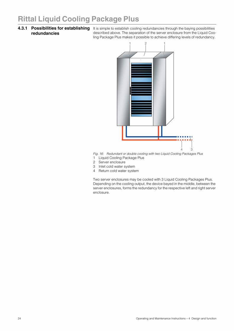
4.3.1 Possibilities for establishingredundancies It is simple to establish cooling redundancies through the baying possibilities described above. The separation of the server enclosure from the Liquid Coo-ling Package Plus makes it possible to achieve differing levels of redundancy.
Fig. 16: Redundant or double cooling with two Liquid Cooling Packages Plus1 Liquid Cooling Package Plus2 Server enclosure3 Inlet cold water system4 Return cold water system
Two server enclosures may be cooled with 3 Liquid Cooling Packages Plus. Depending on the cooling output, the device bayed in the middle, between the server enclosures, forms the redundancy for the respective left and right server enclosure.
34
21 1
24 Operating and Maintenance Instructions – 4 Design and function

Rittal Liquid Cooling Package Plus
Fig. 17: Redundant cooling with three Liquid Cooling Packages Plus1 Liquid Cooling Package Plus2 Server enclosure3 Inlet cold water system4 Return cold water system
Fig. 18: Redundant cooling and doubled, alternating water supply1 Liquid Cooling Package Plus2 Server enclosure3 Inlet cold water system 14 Return cold water system 15 Inlet cold water system 26 Return cold water system 2
34
21 21 1
56 34
21 21 1 2 1 2 1
25 Operating and Maintenance Instructions – 4 Design and function

26 Operating and Maintenance Instructions – 5 Technical specifications
Rittal Liquid Cooling Package Plus5 Technical
specifications
Tab. 2: Technical specifications
Technical specifications Liquid Cooling Package Plus
Model No. SK 3301.480
Rated voltage (V, Hz) 230/1~ 50/60 400/3~/N/PE 50/60
Rated current (A/Hz) 10.5/5011.5/60
3.5/503.8/60
Pre-fuse T (A) 16.0 10.0
Duty cycle (%) 100
Capacity (W/Hz) 2400/502650/60
Useful cooling output L37W15 (kW/Hz)(at 15 °C inlet temperature and a volumetric flow of 60 l/min)
28/5028/60
Air throughput of fans ((m3/h)/Hz)
max. 5000
Coolant Water/glycol mixture(up to 30%)
Coolant inlet temperature (°C) +6 to +20 (ideally +15)
Permissible operating pressure pmax (bar) 5
Ambient temperature range (°C) +6 to +35
Noise level (dB(A))(Open air above reflective flooring, distance 1 m)
64
Width (mm) 300
Height (mm) 2000
Depth (mm) 1200
Weight (kg) max. 230
Fill quantity (l) 9

27 Operating and Maintenance Instructions – 6 Installation – "Getting Started"
Rittal Liquid Cooling Package Plus6 Installation – "Getting
Started"
6.1 Installation conditions In order to ensure problem-free operation of the Liquid Cooling Package Plus, the following conditions for the installation location should be observed:
Supply connections required at the installation site
Tab. 3: Supply connections required at the installation site
Floor conditions- The floor of the installation space should be rigid and level.
- Choose the installation site so that the unit is not situated on a step, unlevel location, etc.
Climatic conditions- The room temperature must be between +6 °C and +40 °C
- The relative air humidity must be below 80%.
Electromagnetic interference- Interfering electrical installations (high frequency) should be avoided.
Type of connection Connection description:
Power connection: - 230 V 50/60 Hzwith connection cable DK 7856.02616 A, 1~, CEE connector, 3-pole
- 400 V, 3~, N, PE, 50/60 Hzwith connection cable DK 7856.02516 A, 3~, CEE connector, 5-pole
Cooling water connection: - +6 °C to +20 °C inlet temperature
- 5 bar permissible operating pressure
- Volumetric flow: depending on design (cf. Chapter 6.5.1, "Cooling output")
- 1" threaded pipe connection
Note:
Please see the notes and data regarding the cold water connection in Chapter 6.4.2, "Cooling water connection" and in Chapter 14.1, "Hydrologi-cal information".
Recommendation:
To keep the Liquid Cooling Package Plus easy to service, maintain a dis-tance of min. 1 m between the front and rear of the device and the nearest wall.
Recommendation:
Room temperature + 22 °C at 50% relative air humidity, according to ASH-RAE guidelines.

Rittal Liquid Cooling Package Plus
6.2 Assembling the LiquidCooling Package Plus
6.2.1 Preparatory work on the server enclosure
Before the Liquid Cooling Package Plus can be bayed onto the server enclos-ure, the following work should be carried out.
- Dismantle the side panels,
- Seal the server enclosure and
- Dismantle the server enclosure door.
Dismantle the side panels
Proceed as follows to dismantle the side panels:• Loosen and remove the 8 assembly screws found on each side panel of the
server enclosure.
• Remove all side panel securing elements from the side of the server enclos-ure onto which the Liquid Cooling Package Plus is to be bayed.
• Dismantle both side panel mountings from the upper mounting rail of the server enclosure. Use an appropriate lever to do this.
• Loosen and remove the screws on both of the side panel mounting brackets (upper and lower) in the middle of the mounting rail.
• Loosen and remove the screws from the 6 side panel holders on the side mounting rails.
Seal the server enclosureIn order to ensure the targeted air routing in the system, the server enclosure is horizontally divided into warm air and cold air sections by sealing the 482.6 mm (19") level.Proceed as follows to seal the 482.6 mm (19") level:• If the server enclosure is only partially configured, seal the open sections of
the 482.6 mm (19") level using blanking plates. Screw these tightly into the server rack from the front side.
• Fasten the broader (Model No. SK 3301.370/3301.320) of the two foam strips from the Liquid Cooling Package Plus accessories from outside onto one of the front supports of the server rack (cf. Fig. 19). Make sure to install this strip on the side of the server enclosure onto which the Liquid Cooling Package Plus is to be bayed.
• Fasten the smaller (Model No. SK 3301.380/3301.390) of the two foam strips from the Liquid Cooling Package Plus accessories from outside onto one of the front supports of the server rack (cf. Fig. 19). Make sure to install this strip on the side of the server enclosure which will again be sealed by a side panel.
Note:
It is only necessary to dismantle the side panels when the Liquid Cooling package is to be bayed onto a previously erected server enclosure. Otherwise, this work is not necessary.
Caution! Risk of injury!
The side panel holders have sharp-edged teeth, which allow for an eart-hing of the server enclosure's side panel.
Note:
The blanking plates are available in various heights (U) from the Rittal ac-cessory range.
28 Operating and Maintenance Instructions – 6 Installation – "Getting Started"

Rittal Liquid Cooling Package Plus
Fig. 19: Foam strip on a server rack support 1 Foam strip2 Server rack
• If devices which require cooling via sideways air throughput (e.g. switches, router, etc.) are built into the server enclosure, cut-outs must be incorporated into the foam strips.
• To do this, cut out a piece of the foam strip with a sharp knife.
• If several devices which require sideways air throughput are included, cut out several pieces of the foam strip, as is appropriate, so that, ultimately, there is a cut-out in the foam to the left or right in the height of each such device in the server rack. Ensure that there are no gaps on the warm air side of the device (Fig. 20, item 3).
• Cut additional pieces from the foam strips with a sharp knife that are at least as long as the height of the built-in devices.
• Attach the foam strips to the cold air side of the devices facing backward (Fig. 20, item 4). Ensure that you attach the strips such that all fans built into the devices can draw air and that none of them are blocked.
1
2
Note:
The foam strips can be attached between the front and rear supports of the server rack along the entire depth of the devices with air throughput at the sides (Fig. 20, item 5).
29 Operating and Maintenance Instructions – 6 Installation – "Getting Started"

Rittal Liquid Cooling Package Plus
Fig. 20: Placement of foam strips for devices with sideways air throughput - top view1 Liquid Cooling Package Plus2 Server enclosure3 Foam strips on warm air side4 Foam strips on cold air side5 Area in which the foam strips can be positioned
• If there is any remaining length of the foam strip on the server rack, cut it off at the top edge of the rack.
• On the side of the server enclosure opposite the Liquid Cooling Packing Plus, mount a side panel on the two side panel mountings. Align it with the front and rear side of the enclosure.
• Using the 8 assembly screws, screw the side panel firmly onto the side panel holders and the side panel mounting brackets.
• Seal off any cable entries which may be present with corresponding brush strips or similar.
Dismantle the server enclosure doorBefore baying a Liquid Cooling Package Plus, one or both of the server enclo-sure doors must be dismantled so that the attachment points for the baying connectors are accessible and are not covered by a door edge.
2
3
5
4
5
1
Note:
The Liquid Cooling Package Plus can, as desired, be bayed onto a server enclosure with a width of either 600 mm or 800 mm. Thus, the Liquid Cooling Package Plus accessories include a total of four foam strips with differing di-mensions.
The foam strips for a 600 mm wide server enclosure may be ordered with the following numbers from the Rittal accessory range:- Model No. SK 3301.370 for the LCP side
- Model No. SK 3301.380 for the side with the side panel
The foam strips for a 800 mm wide server enclosure may be ordered with the following numbers from the Rittal accessory range:- Model No. SK 3301.320 for the LCP side
- Model No. SK 3301.390 for the side with the side panel
30 Operating and Maintenance Instructions – 6 Installation – "Getting Started"

Rittal Liquid Cooling Package Plus
Proceed as follows to dismantle a server enclosure door:• Remove the sealing bungs from the four door hinges with an appropriate tool
(e.g. screwdriver).
• Release and open the server enclosure door.
• Loosen the hinge bolts from the four door hinges by raising them with an ap-propriate tool (e.g. screwdriver). Pull the bolts out of the hinge bolt holding fix-ture up to the catch (see Fig. 21, Step A).Begin with the lowest door hinge.
Fig. 21: Door hinge – dismantling1 Door hinges2 Hinge bolt holding fixture3 Hinge joint4 Server enclosure door
• Remove the server enclosure door (see Fig. 21, Step B).
Note:
It is only necessary to dismantle a server enclosure door when the Liquid Cooling Package Plus is to be bayed onto a previously erected server en-closure. Otherwise, this work is not necessary.If the Liquid Cooling Package Plus is to be set up with a new server enclos-ure, proceed according to the enclosure's assembly instructions and bay the Liquid Cooling Package Plus onto the server enclosure before assemb-ling the server enclosure doors.
1
1
2
4
3
A
A
B
Note:
Support the server enclosure door so that it will not fall as the door hinges are loosened. If needed, work with a second person.
31 Operating and Maintenance Instructions – 6 Installation – "Getting Started"

Rittal Liquid Cooling Package Plus
6.2.2 Installation and baying of theLiquid Cooling Package
Fig. 22: Liquid Cooling Package Plus - rear1 Enclosure door2 Cover3 Assembly screws4 Mounting hole
• Position the Liquid Cooling Package Plus on the side of the server enclosure to which it is to be bayed.
• Align the Liquid Cooling Package Plus with the server enclosure using the le-velling feet. Ensure that the Liquid Cooling Package Plus is aligned levelly and that both enclosures are adjusted to the same height and are vertically aligned to each other.
• Dismantle the door of the Liquid Cooling Package Plus whose hinges are on the side on which the server enclosure is to be bayed. Proceed as described in Chapter 6.2.1, "Preparatory work on the server enclosure".
• Loosen both assembly screws from the cover (Fig. 22, item 3) and remove the cover (Fig. 22, item 2).
• Using assembly screws, fasten three baying connectors each (Fig. 23, item 3) onto the intended attachment points in the frame on the front and rear sides of the Liquid Cooling Package Plus (Fig. 23, item 1).
1
2
4
4
3
3
Note:
If the Liquid Cooling Package Plus is to be bayed between two server enclo-sures, both doors of the LCP Plus must be dismantled before the baying connector is installed and the cover must be removed from the lower section of the rear so that the attachment points for the baying connector are acces-sible.
32 Operating and Maintenance Instructions – 6 Installation – "Getting Started"

Rittal Liquid Cooling Package Plus
Fig. 23: Liquid Cooling Package Plus on a server enclosure - rear1 Liquid Cooling Package Plus2 Server enclosure3 Baying connector
• Using the corresponding assembly screws, fasten the baying connectors (Fig. 23, item 3) onto the intended attachment points in the frame on the front and rear sides of the server enclosure (Fig. 23, item 2). As needed, press the Liquid Cooling Package Plus lightly against the server enclosure in order to bring the baying connectors into alignment with the attachment points.
• Then, check the stability of the Liquid Cooling Package Plus once more and adjust the levelling feet if necessary.
1
3
3
3
2
33 Operating and Maintenance Instructions – 6 Installation – "Getting Started"

Rittal Liquid Cooling Package Plus
6.2.3 Assembly of the side panelon the Liquid Cooling Package Plus
If the Liquid Cooling Package Plus is not bayed between two server enclosures, close it off with a side panel. Proceed as follows to assemble the side panel: • Remove the various assembly components from the optional side panel pa-
ckage (Model. No. SK 8100.235) or use those from a server enclosure which has already been dismantled.
• Using the assembly screws, mount the assembly components (2 side panel mountings, 2 side panel mounting brackets, 6 side panel holders) onto the side of the Liquid Cooling Package Plus which is opposite to the server en-closure.
• Place both side panel mountings (Fig. 24, item 1) as symmetrically as pos-sible onto the upper mounting rail of the LCP Plus and, using your hand, press them firmly in place.
• Screw down the two side panel mounting brackets (Fig. 24, item 2) above and below in the middle of the mounting rail using one screw each.
• Screw down 3 side panel holders (Fig. 24, item 3) onto each of the two side assembly rails with one screw each.
Fig. 24: Assembly components for the side panel1 Side panel mounting2 Side panel mounting bracket 3 Side panel holder
• Mount a side panel onto the two side panel mountings of the Liquid Cooling Package Plus and align them to the front and rear sides of the unit.
• Using the 8 assembly screws, screw the side panel firmly onto the side panel holders and the side panel mounting brackets.
Caution! Risk of injury!
The side panel holders have sharp-edged teeth, which allow for an eart-hing of the side panel through the Liquid Cooling Package Plus.
1
12
2
3
3
34 Operating and Maintenance Instructions – 6 Installation – "Getting Started"

Rittal Liquid Cooling Package Plus
6.3 Fan installation As delivered, the Liquid Cooling Package Plus contains six fan modules. If a fanmodule is defective, it can be replaced during operation without tools - quickly and easily.
6.3.1 Removing a fan module Proceed as follows to remove a fan module:• Open the rear door of the Liquid Cooling Package Plus.
Fig. 25: Fan plug-in unit1 Fan plug-in unit2 T handle3 Handle
• Open the fan module lock by turning the T handle (fig. 25, item 2) anticlock-wise a quarter of a rotation. (Fig. 25, item 2).
Fig. 26: Opening the T handle
1
32
35 Operating and Maintenance Instructions – 6 Installation – "Getting Started"

Rittal Liquid Cooling Package Plus
• Using the handle (Fig. 25, item 3), pull the fan module completely out of thefan plug-in unit.
Fig. 27: Pulling out the fan module
Caution! Risk of injury!
Only pull on the handle when removing the fan module. There is a dan-ger of trapping between the main carrier of the fan module and the edges of the gaps in the floor of the fan plug-in unit.
Caution! Risk of injury! Risk of damage!
While pulling the fan module out of the fan plug-in unit, support it from below. It cannot be held by the handle alone.
36 Operating and Maintenance Instructions – 6 Installation – "Getting Started"

Rittal Liquid Cooling Package Plus
Removing the lower fan moduleAs delivered, the fan module in the lower fan plug-in unit is covered by the ver-tically installed control unit of the water module (RLCP water). For this reason, you must remove the control unit of the water module before you can remove the lower fan module. Proceed as follows:• Open the rear door of the Liquid Cooling Package Plus.
Fig. 28: Water module control unit1 Water module control unit (RLCP water)2 Mounting plate3 Control unit holder4 Thumb screw
• Loosen both thumb screws (Fig. 28, item 4) from the control unit holder (Fig. 28, item 3) and completely unscrew them.
• Remove the control unit together with the holder (Fig. 28, item 1 and item 3) from the mounting plate (Fig. 28, item 2) and set it down outside the Liquid Cooling Package Plus.
•
• Open the fan module lock by turning the T handle (fig. 25, item 2) anticlock-wise a quarter of a rotation. (Fig. 25, item 2).
• Using the handle (Fig. 25, item 3), pull the fan module completely out of the fan plug-in unit.
1
2
34
4
Note:
There is no need to seperate any conductors from the water module control unit (RLCP water) to remove the fan module.
Caution! Risk of injury!
Only pull on the handle when removing the fan module. There is a dan-ger of trapping between the main carrier of the fan module and the edges of the gaps in the floor of the fan plug-in unit.
Caution! Risk of injury! Risk of damage!
While pulling the fan module out of the fan plug-in unit, support it from below. It cannot be held by the handle alone.
37 Operating and Maintenance Instructions – 6 Installation – "Getting Started"

Rittal Liquid Cooling Package Plus
6.3.2 Installing a fan module Proceed as follows to install a fan module:Fig. 29: Fan plug-in unit1 Fan plug-in unit2 T handle3 Slide rails
• Place the fan module onto the slide rails (Fig. 29, item 3) of the fan plug-in unit and push it in until it reaches the stop position.
Fig. 30: Plugging in the fan module
1
3
2
3
38 Operating and Maintenance Instructions – 6 Installation – "Getting Started"

Rittal Liquid Cooling Package Plus
• Close the fan module lock by turning the T handle (Fig. 29, item 2) clockwisea quarter of a rotation.
Fig. 31: Closing the T handle
Inserting the lower fan moduleAfter you have installed the lower fan module as described above, you must then install the water module control unit. Proceed as follows:
Fig. 32: Water module control unit1 Water module control unit (RLCP water)2 Mounting plate3 Control unit holder4 Thumb screw
• Place the control unit together with the holder (Fig. 32, item 1 and item 3) onto the mounting plate (Fig. 32, item 2) in the Liquid Cooling Package Plus.
• Insert both thumb screws (Fig. 32, item 4) and tighten them.
1
2
34
4
39 Operating and Maintenance Instructions – 6 Installation – "Getting Started"

Rittal Liquid Cooling Package Plus
6.4 Connecting theLiquid Cooling Package Plus
6.4.1 Electrical connection
6.4.1.1 General
The Liquid Cooling Package Plus' power supply is made over either a separate 3-pole or 5-pole supply, as desired. The device is always delivered with a 5-pole mains connection socket so that the user can attach a connection cable with a mains plug (3-pole or 5-pole) that corresponds to local requirements. Re-levant connection cables available from Rittal accessories (Model No. DK 7856.025 or DK 7856.026).
Two of fan modules installed in the Liquid Cooling Package Plus are on a sepa-rate phase.
If the Liquid Cooling Package Plus is connected to the mains using a 3-pole, single-phase, 230 V connection cable (L, N, PE; DK 7856.026), one of the pha-ses must be bridged to the other two. This is already implemented in the 5-pole plug.
Note:
Please keep this electrical documentation readily available so that it is al-ways on hand when needed. This is the only documentation which is autho-ritative for the unit.
Caution!
Work on electrical systems or equipment may only be carried out by an electrician or by trained personnel guided and supervised by an electri-cian. All work must be carried out in accordance with electrical engi-neering regulations.
The unit may only be connected after the above-named personnel have read this information.
Use insulated tools.
The connection regulations of the appropriate power company are to be followed.
The voltage values shown in the wiring plan or on the rating plate must match the mains voltage.
The pre-fuse specified in the wiring plan or on the rating plate should be provided as power protection. The unit must be individually fused.
The unit must be connected to the mains via an isolating device which ensures at least 3 mm contact opening when switched off.
The mains connection may only be made using the connection cable which extends from the unit.
No additional control equipment may be connected upstream of the de-vice at the supply end.
40 Operating and Maintenance Instructions – 6 Installation – "Getting Started"

Rittal Liquid Cooling Package Plus
If the Liquid Cooling Package Plus is connected to the mains using a 5-pole connection cable (400 V, 3~, N, PE; DK 7856.025), three separate phases (L1, L2, and L3) are available.In this way, if one connection phase fails, four fan modules will still be supplied with power and the Liquid Cooling Package Plus will continue to function (red-undancy).6.4.1.2 Electrical connection with the included 5-pole plug
5-pole, 3-phase connectionTo connect the Liquid Cooling Package Plus to the mains using a 5-pole, 3-pha-se connection cable, proceed as follows:
• Remove approximately 45 mm from the rubber cover of the sheathed flexible cable.
• Trim the neutral conductor (N) and the three phase conductors (L1, L2, and L3) to a length of approximately 35 mm. Leave the length of the PE conductor at approximately 45 mm.
• Remove approximately 9 mm from the insulation of all conductors with a sui-table tool.
Fig. 33: Dimensions for removing the rubber cover and insulation
• Attach wire end ferrules without insulating collars to the ends of the conduc-tors. To crimp the wire end ferrules, use a suitable crimping tool with an inte-gral lock to prevent the tool from opening prematurely.
• Connect all conductors to the connection plug (X-Com plug).
• Insert a screwdriver into an activation opening (Fig. 34, item 1) and open the screw terminal clamping point of the conductor entry (Fig. 34, item 2).
• Insert the conductor completely into the conductor entry and then remove the screw driver to close the screw terminal clamping point.
Note:
The cross section and the fusing of the connection cable may be found in Chapter 14.4, "Circuit diagram".
Danger!
Take outmost care not to short-circuit one of the phases with the zero conductor or the earth conductor. Otherwise, there is a risk of damage or injury.
45
9 9
41 Operating and Maintenance Instructions – 6 Installation – "Getting Started"

Rittal Liquid Cooling Package Plus
Fig. 34: Connection plug - rear1 Activation opening of the screw terminal clamping point for the conductor
entry2 Conductor entry
• Press the bottom piece of the strain relief housing from below onto the con-nection plug.
• Guide the conductors in the strain relief housing, as displayed in Fig. 35, and secure the sheathed flexible cable to the strain relief housing with a cable clamp.
Fig. 35: Connection plug with strain relief housing1 Strain relief for conductors with Ø > 12 mm2 Strain relief for conductors with Ø < 2 mm
1
2
Note:
The configuration of the Connection plug may be found in Chapter 14.4, "Circuit diagram".
Danger!
Take upmost care not to short-circuit one of the phases with the zero conductor or the earth conductor. Otherwise, there is a risk of damage and injury.
1 2
Note:
To provide adequate strain relief for cables with a diameter of <12 mm as well, it is necessary to install a second cable clamp underneath the cable (Fig. 35, item 2).
42 Operating and Maintenance Instructions – 6 Installation – "Getting Started"

Rittal Liquid Cooling Package Plus
• Close the strain relief housing by pressing the top piece of the housing fromabove onto the bottom piece (Fig. 36).
Fig. 36: Closing the strain relief housing
3-pole, single-phase connectionTo connect the Liquid Cooling Package Plus to the mains using a 3-pole, sing-le-phase connection cable, proceed as follows:
• Remove approximately 45 mm from the rubber cover of the sheathed flexible cable.
• Trim the neutral conductor (N) and the phase conductor (L) to a length of ap-proximately 35 mm. Leave the length of the PE conductor at approximately 45 mm.
• Remove approximately 9 mm from the insulation of all conductors with a sui-table tool.
Fig. 37: Dimensions for removing the rubber cover and insulation
• Attach wire end ferrules without insulating collars to the ends of the conduc-tors. To crimp the wire end ferrules, use a suitable crimping tool with an inte-gral lock to prevent the tool from opening prematurely.
• Bypass the phase connections on the connection plug using the two included bridges (Fig. 38, item 1).:Place one bridge between phase conductors L1 and L2 and one bridge between phase conductors L2 and L3.
45
9 9
43 Operating and Maintenance Instructions – 6 Installation – "Getting Started"

Rittal Liquid Cooling Package Plus
Fig. 38: Schematic diagram of the connection plug with strain relief housing1 Bridge for bridging the phase conductors2 Phase conductor (L)3 Neutral conductor (N)4 PE conductor
• To connect the connection plug, proceed as described in the section "5-pole, 3-phase connection".
Fastening the connection cableThe connection cable must be fastened for the electrical connection of the Li-quid Cooling Package Plus. Proceed as follows:
• Insert the cable tie and spreading anchor from the accessories into the pro-vided hole on the top of the Liquid Cooling Package Plus.
• Lay the connection cable and connect it to the connection socket.
• Fasten the connection cable with the cable tie.
1
23
4
Note:
The following bending radii must not be exceeded for a fixed installation of the connection cable.
5-pole connection cable: 4 x external diameter3-pole connection cable: 3 x external diameter
44 Operating and Maintenance Instructions – 6 Installation – "Getting Started"

Rittal Liquid Cooling Package Plus
6.4.2 Cooling water connection The Liquid Cooling Package Plus is connected to the cold water network viatwo 1" threaded pipe connections (external thread) on the inlet and return, lo-cated on the lower rear side of the unit. The connecting pieces of both pipes are composed of T pieces, to allow for the option of connecting from the rear or through the raised floor.
Fig. 39: Cold water network connection:1 Cooling water return (outlet) with1" external thread2 Cooling water flow (inlet) with 1" external thread
Note:
As much as possible, use armoured hoses for the cooling water hoses.The water connection may be made in a fixed manner using solid pipes as well. This may be done locally by the appropriate qualified person.
Note:
When tightening the coupling connection, use an appropriate tool to provide counter-support on the primary connection to ensure over-tightening is not performed (on the Liquid Cooling Package Plus and on the building ser-vices).
1 2
Note:
To ensure proper functioning of the control valve, a bypass or a water ham-mer arrestor should be provided.
Caution!
When installing, observe the applicable specifications concerning wa-ter quality and water pressure.
45 Operating and Maintenance Instructions – 6 Installation – "Getting Started"

Rittal Liquid Cooling Package Plus
Optionally, the cooling water connection may be made from below through the raised floor. This may be done through a built-in T piece.Fig. 40: Mounting hole for the cooling water connection through the raised floor1 Cooling water flow2 Cooling water return3 Liquid Cooling Package Plus rack
In case of a low water inlet temperature (<12 °C), the inlet and return lines should be appropriately insulated. If this is not done, condensate may form on the supply lines.
2 3
1
150
(45,
5)20
6
(297
)
(45)
Note:
It is possible to test the flow of the water cycle immediately after connection on the graphical display (touchscreen). In addition, you must first check whether the control valve is completely open (see Chapter 6.6.2, "Operation in stand-alone mode"). If the control valve is closed or only partially open, it can be opened in manual mode over a network connection using the setup screen (see Chapter 6.7.1, "Visualisation", page 68).
Note:
The building-side piping should be designed according to the Tichelmann Principle in order to maintain a hydraulically balanced system. If this is not the case, the flow volume of each Liquid Cooling Package Plus must be assured by using a flow quantity regulator.
Ideally, the Liquid Cooling Package Plus is connected to the cooling water system using a water/water heat exchanger.Advantage:• Reduction of water volumes in the secondary circuit,
• Setting of a defined water quality,
• Setting of a defined input temperature and
• Setting of a defined volumetric flow.
46 Operating and Maintenance Instructions – 6 Installation – "Getting Started"

Rittal Liquid Cooling Package Plus
Notes on water qualityFor safe operation, it is vital that the VBG guidelines on cooling water are ob-served (VGB R 455P). Cooling water must not contain any limescale deposits or loose debris, and it should have a low level of hardness, particularly a low level of carbonate hardness. For recooling within the plant, the carbonate hard-ness should not be too high. On the other hand, however, the water should not be so soft that it attacks the operating materials. When recooling the cooling water, the salt content should not rise too high as the result of evaporation of large quantities of water, since electrical conductivity increases as the concen-tration of dissolved substances rises, and the water thereby becomes more corrosive. For this reason, it is not only always necessary to add a correspon-ding quantity of fresh water, but also to remove part of the enriched water. Gyp-siferous water is unsuitable for cooling purposes because it has a tendency to form boiler scale, which is particularly difficult to remove. Furthermore, cooling water should be free from iron and manganese, because deposits may occur which settle in the pipes and block them. At best, organic substances should only be present in small quantities, because otherwise sludge deposits and mi-crobiological contamination may occur.Note:
To avoid frost and corrosion damage as well as biological contaminants, Rit-tal GmbH & Co. recommends that a water/glycol mixture be used up to max. 30% glycol.
Note:
The Liquid Cooling Package Plus is secured against excess pressure as re-gards a maximum permissible pressure (PS) of 8 bar if no cooling medium liquid is trapped. If shut-off valves that could cause cooling medium liquid getting trapped are installed on site, pressure relief vessels with safety val-ves (8 bar blowing-off pressure) must be built into the coolant circuit of the recooling system.
Note:
Before operation with water is started, all supply lines must be adequately flushed.Rittal GmbH & Co. KG also recommends the implementation of a magnetic filter in the cooling water flow for each Liquid Cooling Package or a central magnetic filter to avoid devices becoming contaminated with suspended matter and impurities containing ferrite.
Note:
To avoid the loss of fluids due to diffusion (open and closed systems) or eva-poration (open systems), it is recommended to employ automatic filling.
47 Operating and Maintenance Instructions – 6 Installation – "Getting Started"

Rittal Liquid Cooling Package Plus
6.4.3 Condensate dischargeconnectionAny condensate which may develop is collected in the condensate collecting tray in the water module of the Liquid Cooling Package Plus.
Fig. 41: Water module1 Cooling water flow (inlet)2 Condensate discharge (from condensate pump)3 Condensate discharge (outlet)4 Condensate overflow (no pressure), emergency overflow
Upon reaching a defined condensate level in the collecting tray, a float actua-ted switch activates a pump, which pumps off the condensate. The condensate that is pumped out is guided out of the Liquid Cooling Package Plus through a discharge hose (dimensions: external Ø = 8 mm, internal Ø = 6 mm) to an ex-ternal drain.In addition, the Liquid Cooling Package Plus is equipped with a condensate overflow hose that guides any condensate out of the Liquid Cooling Package Plus without pressure into an external drain, if the condensate pump or float-actuated switch fails.Both the condensate discharge hose and the condensate overflow hose are to be connected to a drain equipped with a siphon trap.
1
3
2
4
Note:
In order to ensure safe condensate discharge, the following points should be observed:- Lay the discharge hose without kinks
- Do not constrict the hose cross section
- Lay the condensate overflow hose with a gradient
Note:
In order to avoid increased condensation and to reduce energy use, the cooling water temperature should be adapted to match the required cooling output.
48 Operating and Maintenance Instructions – 6 Installation – "Getting Started"

Rittal Liquid Cooling Package Plus
6.5 Cooling operation andcontrol behaviourIf the LCP Plus is provided with power, the control valve controls the cooling wa-ter flow according to the established setpoint temperature. For more detailed explanations, please refer to Chapter 4.2, "Function".
6.5.1 Cooling output The following diagrams show the cooling output of the Liquid Cooling Package Plus in [kW], depending on the cooling water flow [l/min] and the air inlet tem-perature [°C] for various flow temperatures. They are meant to assist the ope-rator in the planning phase to determine the water circuit necessary for the system.
Fig. 42: Cooling output of the Liquid Cooling Package Plus, with flow temperature 10 °C
10
15
20
25
30
35
10 15 20 25 30 35 40 45
Air admittance 20˚CAir admittance 25˚C
Inlet temperature [°C]
Coo
ling
out
put
[Wat
t]
49 Operating and Maintenance Instructions – 6 Installation – "Getting Started"

Rittal Liquid Cooling Package Plus
Fig. 43: Cooling output of the Liquid Cooling Package Plus, with flow temperature 15 °C
6.5.2 Pressure loss The following diagram shows the pressure loss of the Liquid CoolingPackage Plus in [bar], depending on the volumetric flow [l/min]. It is meant to assist the operator in the planning phase to determine the water pressure of the cold wa-ter supply system necessary for the system.
Fig. 44: Pressure loss in the Liquid Cooling Package Plus
10,00
15,00
20,00
25,00
30,00
35,00
20,0 25,0 30,0 35,0 40,0 45,0 50,0 55,0 60,0 65,0
Air admittance 20˚CAir admittance 22˚CAir admittance 25˚C
Inlet temperature [°C]
Coo
ling
out
put
[Wat
t]
0
0,2
0,4
0,6
0,8
1
1,2
1,4
1,6
0 10 20 30 40 50 60 70 80Volumetric flow [l/min]
Pre
ssur
e lo
ss [
bar
]
50 Operating and Maintenance Instructions – 6 Installation – "Getting Started"

Rittal Liquid Cooling Package Plus
6.6 Operation6.6.1 General A Basic CMC forms the control unit of the Liquid Cooling Package Plus. Its jobs are to:- Retrieve all measurements over the I2C bus from the fan modules and the wa-
ter module (temperature, speed, flow, etc.).
- Evaluate all measurements and generate alarm and warning signals.
- Calculate the thermal output of the flow and return temperature as well as de-termine the water flow volume.
- Control air temperature in the server enclosure by regulating the fan speed and the water volume through the heat exchanger.
- Set the setpoint temperature for the cold air blown in (factory setting 20 °C).
- Control a graphical display (touchscreen) over a RS-232 interface.
- Display the measurements and settings of parameters and setpoints over the web interface of the CMC.
- Poll the sensor and setting values over SNMP.
Fig. 45: Control unit Liquid Cooling Package (Basic CMC) – front1 Button "C"2 Status LED (alarms and warnings)3 Status LED (network status)4 Hyperterminal
The control unit polls all measurements from the connected fan modules and water module. This communication takes place over the I2C bus. The control unit thus serves as the master and polls the measurements from the slave units or returns the setting data.The measurements which are delivered from the individual modules are evalu-ated by the control unit and possible warning and alarm signals are generated. If a new warning or alarm occurs, the internal beeper communicates this. At the same time, the alarm relay is switched. This acoustic alarm may be cleared by pressing down the clear button "C" briefly. At the same time, the alarm relay is reset. The exact cause of malfunction can be displayed in plain text on the con-nected graphical display (touchscreen). The following messages can be dis-played:
Warning messages- Fan speed of fan 1 or 2 from fan unit 1 faulty
- Fan speed of fan 1 or 2 from fan unit 2 faulty
- Fan speed of fan 1 or 2 from fan unit 3 faulty
- Flow faulty
- Control valve faulty
Note:
Further explanations concerning the various setting options and features are available in the CMC-TC system documentation.
CMC - TC
!
CBasic CMC
IOIOI
1 2 3 4
51 Operating and Maintenance Instructions – 6 Installation – "Getting Started"

Rittal Liquid Cooling Package Plus
Alarm messages- Temperature sensor of fan unit 1 (server-in/server-out temperature) faulty- Temperature sensor of fan unit 2 (server-in/server-out temperature) faulty
- Temperature sensor of fan unit 3 (server-in/server-out temperature) faulty
- Low temperature sensor faulty
- Return temperature sensor faulty
- Water module not present
- Leakage message
- No fan module detected
Design of the temperature control circuitThe actual temperature values of the cold air on the air input side (server-in temperature) delivered by the three temperature sensors on the heat ex-changer are used to control the air which is blown into the server enclosure. The average value is determined from the actual temperature values. The control unit constantly compares this (average) actual temperature with the setpoint temperature. If the setpoint temperature is exceeded, the control unit attempts to maintain a constant temperature by opening and closing the control valve. Only when the actual temperature falls below the value of "setpoint temperatu-re" is the control valve kept closed, i.e. no cold water flows through the heat ex-changer. Additionally, the necessary fan speed is determined and controlled through determining the temperature difference between the inlet and the outlet air (server-out temperature / also, in this case, an average value is determined through the fan modules.) The respective setpoint speed for the fans and the setting of the control valve is sent to the connected control units over the I2C bus.
Fig. 46: Control unit of the Liquid Cooling Package Plus (Basic CMC) - rear1 Sockets for additional sensors2 I2C socket socket3 Socket for controlling the graphical display4 Alarm relay sockets5 Network connection6 Power supply
Four additional standard sensors can be connected to the control unit (Basic CMC) to monitor additional physical parameters of the Liquid Cooling Package Plus. The sensors must simply be connected to one of the four sockets on the rear of the control unit (Fig. 46, item 1) and configured via the Basic CMC.
Note:
After turning on for the first time or after repair work, it is possible that the Liquid Cooling Package Plus will operate in emergency operation mode. In order to switch the unit to normal operation (control operation), press down the "C" button (Fig. 45, item 1) once quickly.
Power
24 VDCmax. 2,5A
P-I C21 23 4 IOIOI
1
1 2 3 4 5 6
52 Operating and Maintenance Instructions – 6 Installation – "Getting Started"

Rittal Liquid Cooling Package Plus
The following standard sensors can be connected in addition:Tab. 4: List of standard sensors
6.6.2 Operation in stand-alone mode
In stand-alone mode, the Liquid Cooling Package Plus is operated via the touchscreen of the graphical display on the front door.The user interface of the touchscreen allows the user to navigate between the individual menu options of the Liquid Cooling Package Plus controller using software-controlled buttons (MENU, NEXT, BACK).
Fig. 47: Touchscreen
The following menu options can be accessed:
SensorModel No.
DKMax.
Quantity
Temperature sensor 7320.500 4
Humidity sensor 7320.510 4
Analogue sensor input module "4 - 20 mA" 7320.520 4
Access sensor 7320.530 4
Vandalism sensor 7320.540 4 x 5
Airflow sensor 7320.550 4
Smoke alarm 7320.560 4
Motion sensor 7320.570 4
Digital input module 7320.580 4
Digital relay output module 7320.590 4
Voltage monitor 7320.600 4
Voltage monitor with switch output 7320.610 4
48 V voltage monitor 7320.620 4
Leakage sensor 7320.630 4
Note:
Further explanations concerning the various setting options and features are available in the CMC-TC system documentation.
Menu option Explanation
Server-intemperature
Display of the average of the three server-in temperatures from the sensors on the heat exchanger.
Alarms / Warnings
Display of the alarm and warning message in plain text (cf. Chapter 6.6.1, "General").
53 Operating and Maintenance Instructions – 6 Installation – "Getting Started"

Rittal Liquid Cooling Package Plus
Tab. 5: Menu options of the Liquid Cooling Package Plus controller
Setting the setpoint for the server-in temperature• Press the [NEXT] or [BACK] buttons repeatedly until the graphical display
displays the menu option "Setpoint".
• Open entry mode for the setpoint by pressing the [EDIT] button.
• Enter the setpoint by pressing the [+] and [-] buttons. The value can be set between 10 °C and 40 °C.
• To increase the setpoint, press the [+] button until the desired setpoint has been reached.
• To decrease the setpoint, press the [-] button until the desired setpoint has been reached.
• Confirm the entry by pressing the [ENTER] button.
• To cancel the entry of the setpoint, press the [ESC] button.
Air temperatures
Display of the six air temperatures (3 x server-in, 3 x server-out) determined by the temperature sensors.
Fan speed Display of the fan speeds.
Water system Display of - the water flow and water return temperatures,
- the setpoint and actual position of the control valve,
- the flow in [l/min] and the cooling output determined from the wa-ter temperature and the flow volume.
Setpoint Display and entry of the setpoint for the server-in temperature.
IP-Adress / Software-version
Display of the current IP address and software version of the Basic CMC.
Menu option Explanation
Note:
The input mode for the setpoint for the server-in temperature could be lo-cked, to avoid access by unauthorised personel. Further explanations are available in Chapter 6.7, "Extended Basic CMC options with network connection".
Note:
Connect the Basic CMC to a network for extended setting options (cf. Chapter 6.7, "Extended Basic CMC options with network connection").
54 Operating and Maintenance Instructions – 6 Installation – "Getting Started"

Rittal Liquid Cooling Package Plus
6.7 Extended Basic CMCoptions with network connection
By connecting the Liquid Cooling Package Plus control unit (Basic CMC) to a network, you are able to call up various measurements and warning or alarm messages. These may then be further processed (e.g. via a Web browser, SNMP, etc.). Furthermore, various values can be set over the network and then sent to the control unit. If the control unit is connected to a network, the status LED (Fig. 45, item 3) flashes when the unit is polled over the network via the Ethernet interface.
The following values can be called up and processed over the network in the browser window of the Basic CMC software:- Actual temperature
(average value of the cold air temperature, as determined by the control unit, which is used to regulate)
- Cooling output(calculated thermal output which is removed from the server enclosure)
- Alarm and warning messages (messages which give further information concerning the cause of a warning or an alarm)
- Setpoint fan speed/control valve(the fan speed set by the control unit for the fan modules as well as the posi-tion of the control valve (open/closed))
- Actual temperature/fan speeds(temperature level measured behind the heat exchanger (cold air temperatu-re) as well as the actual fan speeds of the fans for each fan module)
- Flow/return temperature/flow volume(the values of the flow and return temperatures as reported by the heat ex-changer module as well as the flow volume in l/min)
The following values can be edited in the browser window of the Basic CMC software and then sent to the control unit.- Setpoint temperature
(from the control unit to regulate the setpoint used)
To connect the Liquid Cooling Package Plus to a network, connect one of the network ports on the Liquid Cooling Package Plus control unit (Fig. 49, item 5) to a network access port using a category 5 patch cable.
Fig. 48: Control unit Liquid Cooling Package Plus (Basic CMC) – front1 Button "C"2 Status LED (alarms and warnings)3 Status LED (network status)4 IO connection
CMC - TC
!
CBasic CMC
IOIOI
1 2 3 4
55 Operating and Maintenance Instructions – 6 Installation – "Getting Started"

Rittal Liquid Cooling Package Plus
Fig. 49: Control unit Liquid Cooling Package Plus (Basic CMC) – rear1 Sockets for additional sensors2 I2C socket3 Socket for controlling the graphical display4 Alarm relay sockets5 Network connection6 Power supply
Power
24 VDCmax. 2,5A
P-I C21 23 4 IOIOI
1
1 2 3 4 5 6
56 Operating and Maintenance Instructions – 6 Installation – "Getting Started"

Rittal Liquid Cooling Package Plus
6.7.1 Visualisation Setting and changing the values which are delivered from the Liquid CoolingPackage Plus control unit are explained in the examples presented below.
Status screen
Fig. 50: Status screen of a CMC1 Information display2 Status window3 Navigation display
Fig. 50 shows the status screen of the browser window of a CMC. The screen is divided into three areas. At the left edge of the screen, under the Rittal logo, there is a navigation display which shows the current screen menu. The header of the screen contains an information display. This contains details of the connected units (Name/Liquid Cooling Package Plus), the location of the unit (Location), and the responsible contact person (Contact).
Note:
This documentation refers to the Basic CMC software with the provisional version 6.02. Further explanations concerning the operation and various set-ting options and features are available in the separate Basic CMC documen-tation.Firmware updates for the Basic CMC software are available under www.rimatrix5.com.
23
1
57 Operating and Maintenance Instructions – 6 Installation – "Getting Started"

Rittal Liquid Cooling Package Plus
Fig. 51: Status window1 LCP-Overview2 Graphical overview3 Sensors4 Status line
LCP-OverviewThe following values are displayed in the LCP-Overview area:
Tab. 6: Displays in the LCP-Overview display area
Setting values
Explanation
Server-in tem-perature
Displays the average of the three server-in temperatures from the fan modules.
Server-out temperature
Displays the average of the three server-out temperatures from the fan modules.
Cooling capa-city
Displays the calculated cooling output of the Liquid Cooling Package Plus. The output is calculated from the flow and return temperatures as well as from the flow values of the cooling water circuit (the value is calculated over approximately one to two minu-tes).
Setpoint Displays the current setpoint for the server-in temperature. This setpoint is used to control the server-in temperature using the flow volume of the control valve.
Operating mode
Displays the current operating mode (automatic or manual) in which the LCP Plus is operating.
Fanspeed Displays the currently set fan speed (0 = off / 1 to 4 = speed 1 to 4).
Control valve Displays the current setpoint for the position of the control valve in [%]:- 0% = valve closed,
- 100% = valve open.
Cycles cond. pump
Displays how often the condensate pump has been switched on.
Leakage sen-sor
Status of the Leakage sensor.
2
4
3
1
58 Operating and Maintenance Instructions – 6 Installation – "Getting Started"

Rittal Liquid Cooling Package Plus
Graphical overviewThe following values are displayed in the graphical overview in an illustrated depiction of the Liquid Cooling Package Plus:Tab. 7: Measurements and display values in the graphical overview
SensorsFour additional standard sensors can be connected to the control unit (Basic CMC) to monitor additional physical parameters of the Liquid Cooling Package Plus. The status of these sensors is displayed in this window.
Status lineThe status line displays whether or not the unit is functioning problem-free or if a warning or alarm message is present. The following displays are possible:- No Alarm (green background)
- Warning (orange background)
- Alarm (red background)
Setting values
Explanation
Server-in tem-perature (3x)
Displays the actual temperature and the status of each tempera-ture sensor on the cold air side of the LCP Plus.The temperatures are displayed in real values in [°C]. The status of the temperature sensors displayed in terms of colour:- green = sensor o.k.
- red = sensor defective
Server-out temperature (3x)
Displays the actual temperature and the status of each tempera-ture sensor on the warm air side of the LCP Plus.The temperatures are displayed in real values in [°C]. The status of the temperature sensors displayed in terms of colour:- green = sensor o.k.
- red = sensor defective
Fanspeed (3x) Displays the actual speed and the status of each fan.The temperatures are displayed in real values in [rpm]. The status of the temperature sensors displayed in terms of colour:- green = sensor o.k.
- orange = speed is minor to 400 rpm
The arrangement and the numbering of the fan at the monitor is equivalent to the real arrangement and numbering at the Liquid Cooling Package Plus (fan 1, top/fan 6 bottom).
Flow rate Displays the actual flow rate of the cooling medium in real values in [l/min]. The status of the temperature sensors displayed in terms of colour:- green = sensor o.k.
- orange = sensor defective
Control valve Displays the current setpoint for the position of the control valve in [%]:- 0% = valve closed,
- 100% = valve open.
Water tempe-rature
Displays the actual temperature and the status of the temperature sensor at the cooling water inlet and outlet.The temperatures are displayed in real values in [°C]. The status of the temperature sensors displayed in terms of colour:- green = sensor o.k.
- red = sensor defective
Note:
Further explanations concerning the various setting options and features are available in the CMC-TC system documentation.
59 Operating and Maintenance Instructions – 6 Installation – "Getting Started"

Rittal Liquid Cooling Package Plus
Fig. 52: Status screen with warning message1 Warning message
A warning message is displayed in the status line of the status window in Fig. 52. In this case, the control valve is open (74%), but there is no flow (0 l/min).
Fig. 53: Status screen with alarm message1 Alarm message
An alarm message is displayed in the status line of the status window in Fig. 53. In this case, temperature sensor 1 on the warm air side of the LCP Plus (server-out temperature) is faulty.
You can acknowledge alarm and warning messages as well as the message "Configuration Change" by pressing the "Clear" button.
1
1
60 Operating and Maintenance Instructions – 6 Installation – "Getting Started"

Rittal Liquid Cooling Package Plus
Setup screenFig. 54: Setup window for the actual temperature1 Information display2 Status window3 Navigation display
Fig. 54 shows the setup screen of the browser window of a CMC. The screen is divided into three areas.
In the setup screen, the setup window is located underneath the header. The values which are to be set are shown and entered in this window. Beneath the setup window there are also two buttons, "Accept" and "Reset". These are used to either accept or reject the entries, which have been made.- The "Accept" button is used to accept the changed values.
- The "Reset" button is used to clear the changed values.
Fig. 54 shows the setup window for the server-in temperature. Either the follo-wing values are displayed or the following settings may be made in this screen:
23
1
Note:
The layout of the left edge of the screen and the header corresponds to that of the status screen.
Setpoint Explanation
Unit name: Name of the RLCP unit (max. 10 characters)
Type: Message type
Sensor status: Temperature and status of the message are displayed in colour.
Message text: Text message which appears in the status window(may be edited).
Setpoint high: This setpoint may be used to generate and forward an alarm mes-sage in case of overheating (temperature sensor).
Setpointwarning:
This setpoint may be used to generate and forward a warning message.
Setpoint low: This setpoint may be used to generate and forward an alarm mes-sage in case of overcooling (temperature sensor).
Alarm relay: Serves to switch the PU's alarm relay on and off.
61 Operating and Maintenance Instructions – 6 Installation – "Getting Started"

Rittal Liquid Cooling Package Plus
Tab. 8: Setup value for the server-in temperature
Fig. 55: Setup screen for cooling capacity setpoint.
Fig. 55 shows the setup screen for the cooling capacity setpoint. This shows how much cooling output is being delivered by the recooling systems to the system at the moment.
The temperatures for the following setpoints may be changed in the lower part of the window: - Setpoint server-in temperature
Alarm beeper: Serves to switch the PU's alarm beeper on and off.
Alarm reset: Setting to determine whether triggered alarms are cleared auto-matically or require manual confirmation.
Trap receiver: Choice as to which receiver a trap is sent when status is changed.
Scheduled alarm off:
This point may be used to determine that no alarm should be reported for one or more timers. The time for the timer must be set in the timer menu.
Setpoint Explanation
62 Operating and Maintenance Instructions – 6 Installation – "Getting Started"

Rittal Liquid Cooling Package Plus
Fig. 56: Setup Screen for alarm messages
Fig. 56 shows the setup screen for alarm messages. Either the following values are displayed or the following settings may be made in this screen:
Tab. 9: Setup value for alarm messages
Additionally, the exact cause of the alarm message is displayed in plain text (more than one cause can be displayed). - Temperature sensor of fan unit 1 (server-in/server-out temperature) faulty
- Temperature sensor of fan unit 2 (server-in/server-out temperature) faulty
- Temperature sensor of fan unit 3 (server-in/server-out temperature) faulty
- Inlet temperature sensor faulty
- Return temperature sensor faulty
- Water module not available
- Leakage message
- Fan module not available
Setpoints Explanation
Unit name: Name of the RLCP unit (max. 10 characters)
Type: Message type
Sensor status: Status of the message (displayed in colour).
Message text: Text message which appears in the status window (may be edi-ted).
Alarm relay: Switches the PU's alarm relay on and off.
Alarm beeper: Switches the PU's alarm beeper on and off.
Alarm reset: Setting to determine whether triggered alarms are cleared auto-matically or require manual confirmation.
Trap receiver: Choice as to which receiver a trap is sent when status is changed.
Scheduled alarm off:
This point may be used to determine that no alarm should be reported for one or more timers. The time setting for the timer must be entered in the timer menu.
63 Operating and Maintenance Instructions – 6 Installation – "Getting Started"

Rittal Liquid Cooling Package Plus
Fig. 57: Setup screen for warning messages
Fig. 57 shows the setup screen for warning messages. Either the following va-lues are displayed or the following settings may be made in this screen.:
Tab. 10: Setup value for warning messages
Additionally, the exact cause of the warning message is displayed in plain text (more than one cause can be displayed).- Fan speed of fan 1 or 2 faulty
- Fan speed of fan 3 or 4 faulty
- Fan speed of fan 4 or 5 faulty
- Flow faulty
- Control valve faulty
Setpoints Explanation
Unit name: Name of the RLCP unit (max. 10 characters)
Type: Message type
Sensor status: Status of the message (displayed in colour).
Message text: Text message which appears in the status window (may be edi-ted).
Alarm relay: Switches the PU's alarm relay on and off.
Alarm beeper: Switches the PU's alarm beeper on and off.
Alarm reset: Setting to determine whether triggered alarms are cleared auto-matically or require manual confirmation.
Trap receiver: Choice as to which receiver a trap is sent when status is changed.
Scheduled alarm off:
This point may be used to determine that no alarm should be reported for one or more timers. The time for the timer must be set in the timer menu.
64 Operating and Maintenance Instructions – 6 Installation – "Getting Started"

Rittal Liquid Cooling Package Plus
Fig. 58: Login window
You must enter a password to call up the setup window for the operation data. This is done in the login window depicted in Fig. 58.
If nothing is entered or confirmed in the login window for more than 10 minutes, the password is reset and it must be entered again to call up the setup window for operation data.
Note:
Password: RittalLcp+XXXXXThe five-digit number (XXXXX) is the serial number of the Basic CMC (see page 69, table 13, “General settings for Liquid Cooling Package Plus” ).
Caution!
Never refer the password to unauthorised personnel.
The setup mode only serves for service purpose. Setting up of basic operating parameters should be exclusively carried out by Rittal ser-vice personnel.
65 Operating and Maintenance Instructions – 6 Installation – "Getting Started"

Rittal Liquid Cooling Package Plus
Fig. 59: Setup screen for operation parameters - "Automatic Mode"
Fig. 59 shows the setup screen for the operating parameters of the Liquid Coo-ling Package Plus for the functions in automatic mode. The following are para-meters that are displayed or settings that may be made on this screen:
Displays Explanation
Operating mode
Selection of the Liquid Cooling Package Plus operating mode. Here, automatic mode is selected.
Automatic mode
Pull-down menu for setting the control of the fans and the control valve of the Liquid Cooling Package Plus.
Fig. 60: Setting options
- Full:In this mode, the fan speed and the position of the control valve are controlled automatically.
- Fan only:In this mode, only the fan speed is controlled automatically. The position of the control valve can be set to a fixed position using the function for manual operation. This position is saved and used again after the system is restarted.
- Valve only:In this mode, only the position of the control valve is controlled au-tomatically. The fan speed can be set to a fixed speed using the function for manual operation. This speed is saved and used again after the system is restarted.
66 Operating and Maintenance Instructions – 6 Installation – "Getting Started"

Rittal Liquid Cooling Package Plus
Tab. 11: Operating parameters for automatic mode
Fan control mode
Pull-down menu for setting the calculation mode for automatic con-trol of the fan speeds.The required fan speed for automatic control is determined from the difference of the server-out temperature and the setpoint for the server-in temperature (dT = server-out temperature - server-in tem-perature) and controlled linearly between speeds 1 and 4.The following modes can be selected:
Fig. 61: Setting options
- Average temperature:In this mode, the average value of the server-out temperatures is used to calculate the required fan speed.
- Maximum temperature:In this mode, the highest value of the server-out temperatures is used to calculate the required fan speed.
In addition, the automatic control of the fan speeds can be cont-rolled using the values dT [min. fan speed] and dT [max. fan speed].
dT [min. fanspeed]
The fan operates at the lowest fan speed beneath this temperature difference.
dT [max. fanspeed]
The fan operates at the highest fan speed above this temperature difference.
Sampling time Setting of the control interval for the control valve. In this interval, the actual temperature (average from the measurements of the three fan modules/server-out temperature) is compared with the setpoint (server-in temperature).This is set in seconds [s] between 10 and 60 s (preset to 30 s).
PID componenets
Values for setting the PID control algorithm integrated in the LCP software. The following settings can be made here:- P amount:
Parameter for setting the proportional amount. This is set as a per-centage [%] between 0 and 30% (preset to 10%).
- I amount:Parameter for setting the integral amount. This is set in seconds [s] between 20 and 150 s (preset to 80 s).
- D amount:Parameter for setting the differential amount. This is set in amount per second [1/s] between 0 and 50/s (preset to 0/s).
Cw value Specific thermal capacity of the cooling liquid used.
Setpoint by display
Release options for the setpoint entry of the server-in temperature using the graphical display (touchscreen) of the Liquid Cooling Package Plus:- Enable:
Setpoint entry is possible.
- Disable:Setpoint entry is locked.
Displays Explanation
Caution!
The preset values for the parameters "Sampling time" and "PID compo-nents" are determined experimentally. Only change this values based cases to enhance the type of control.
67 Operating and Maintenance Instructions – 6 Installation – "Getting Started"

Rittal Liquid Cooling Package Plus
Fig. 62: Setup screen for operation parameters - "Manual Mode"
Fig. 62 shows the setup screen for the operating parameters of the Liquid Coo-ling Package Plus for the functions in manual mode.The following are parameters that are displayed or settings that may be made on this screen in addition to the functions in automatic mode:
Tab. 12: Operating parameters for manual mode
Setpoints Explanation
Operating mode
Selection of the Liquid Cooling Package Plus operating mode. Here, manual mode is selected.
Fanspeed Fan speed setting (0 = off / 1 to 4 = speed 1 to 4). The last setting that was made is saved and used again after the system is restarted if the setting "Valve only" is selected in auto-matic mode. Otherwise, the fan modules are controlled automati-cally.
Enable fans Switch off individual fan modules for testing.This function is only possible in manual mode. In automatic mode, all fan modules are activated.
Valve Setting of the opening position of the control valve. This is set as a percentage [%] between 0 and 100%.The last setting that was made is saved and used again after the system is restarted if the setting value "Fan only" is selected in automatic mode. Otherwise, the control valve is controlled auto-matically.
Note:
After the Liquid Cooling Package Plus is connected to the mains or restar-ted, the controller is always in automatic mode.
68 Operating and Maintenance Instructions – 6 Installation – "Getting Started"

Rittal Liquid Cooling Package Plus
Fig. 63: Setup screen „General Setup“
The setup screen "General Setup" is depicted in Fig. 63. All settings are made for the Liquid Cooling Package Plus here:
Tab. 13: General settings for Liquid Cooling Package Plus
Setpoints Explanation
Name Name of the LCP Plus unit (max. 40 characters)
Location Location of the LCP Plus unit (max. 40 characters)
Contact Responsible contact person (max. 40 characters)
Revision / Serialnr.
Revisions and serial numbers of the LCP Plus unit- SW: Software revision
- HW: Hardware revision
- SN: Serial number
Temperature unit
Default setting for the unit of temperature:- Degrees Celsius [°C]
- Degrees Fahrenheit [°F]
Measurement unit
Default setting for the unit of flow:- Litres per minute [l/min]
- Gallons per minute [US-Gallons/min]
Beeper Used to switch the Basis-CMC' alarm beeper on and off.
Quit alarm relay
Used to switch the Basis-CMC' alarm relay on and off.
Alarm relay options
Used to set the switching position that generates an alarm mes-sage.- Open: Message is generated when the relay opens
- Close: Message is generated when the relay closes
Web access Used to set the network access to the LCP Plus:- Full: Full access
- View only: Only view access
- No Access: No access
Actual date Actual Date
Actual time Current time
69 Operating and Maintenance Instructions – 6 Installation – "Getting Started"

Rittal Liquid Cooling Package Plus
Note:
Further explanations concerning the various setting options and features are available in the CMC-TC system documentation.
70 Operating and Maintenance Instructions – 6 Installation – "Getting Started"

Rittal Liquid Cooling Package Plus
7 Hardware andsoftware
7.1 Liquid Cooling Package Plus control unit
7.1.1 Hardware A Basic CMC forms the control unit of the Liquid Cooling Package Plus. Its job is to use the I2C bus to poll the measurements (such the three server-in tempe-ratures, three server-out temperatures, six fan speeds, flow rate, control valve position, flow and return temperatures of the cooling water) from the six fan mo-dules, the sensors on the heat exchanger, and from the water module, to per-form control functions, and to transfer the setpoints (such as the fan speed) to the individual units.
Fig. 64: Control unit Liquid Cooling Package (Basic CMC) – front1 Button "C"2 Status LED (alarms and warnings)3 Status LED (network status)4 Hyperterminal
The control circuit board is built into a standard CMC plastic housing. The fol-lowing components are on the front side of the unit:
Control component
Explanation
Button "C" Use this button to confirm warnings and alarms as well as to set the setpoint for the desired cold air temperature.
Status LED: (alarms and warnings)
Displays the internal status of the control unit through a duo LED (red/green). The various alarm and warning conditions can be shown via this LED.
Status LED: (network status)
Displays the status of the network connection.
CMC - TC
!
CBasic CMC
IOIOI
1 2 3 4
71 Operating and Maintenance Instructions – 7 Hardware and software

Rittal Liquid Cooling Package Plus
Fig. 65: Control unit of the Liquid Cooling Package Plus (Basic CMC) - rear1 Sockets for additional sensors2 I2C socket socket (X 22)3 Socket for controlling the graphical display (X 24)4 Alarm relay sockets5 Network connection (X 23)6 Power supply (X 21)
Various sockets are found on the rear side of the control unit.
Pin assignment of the sockets for additional sensors:1 24 V DC2 Gnd3 Sensor ID 14 Sensor ID 25 Analogue input6 Digital input/output
The 8-pole connector X22 contains the so-called Power-I2C bus.Assignment of the I2C bus:1 - N/C2 - N/C3 - N/C4 - N/C5 - Gnd6 - + 24 V DC7 - P-SDA8 - P-SCL
The graphical display on the front door is controlled via an RS-232 connection with the RJ12 socket X24.X24 pin assignment:1 24 V DC2 Gnd3 TxD4 RxD5 RTS6 CTS
Alarm relay socket pin assignment:1 24 v DC2 Gnd- Relay COMMON3 N/C4 Relay normally closed5 Relay common6 Relay normally open
Power
24 VDCmax. 2,5A
P-I C21 23 4 IOIOI
1
1 2 3 4 5 6
72 Operating and Maintenance Instructions – 7 Hardware and software

Rittal Liquid Cooling Package Plus
The RJ45 socket X23 is used to make an optional Ethernet connection to a net-work.1 Tx+2 Tx-3 Rx+4 n.c.5 n.c.6 Rx-7 n.c.8 n.c.Power supply pin assignment:1 24 V DC2 Gnd
The control unit is supplied with power via a separate power pack (DK 7320.425) and a Kycon socket. All modules are supplied with 24 V DC and are fed together with the I2C bus.
73 Operating and Maintenance Instructions – 7 Hardware and software

Rittal Liquid Cooling Package Plus
7.2 Control unit for fan module(RLCP fan)
7.2.1 Hardware
Fig. 66: Control unit fan module – front1 Power supply (X3)2 Fuse (2.5 A)3 Fuse (2.5 A)4 Power supply for fan 1 (X4)5 Power supply for fan 2 (X5)
Fig. 67: Control unit fan module – rear1 Socket for control cable (X26)2 Socket for air outlet temperature sensor (X8)3 Socket for air inlet temperature sensor (X9)4 Socket for tachometer Fan 1 (X6)5 Socket for tachometer Fan 2 (X7)6 Status LED
One control unit (RLCP fan) is assigned to two fan modules. It controls their in-dividual components. The control voltage is +24V and is fed together with the I2C bus through connector X26 of the control unit (Basic CMC).X26 pin assignment:1 Address signal (TTL Level)2 Gnd3 Address signal (TTL Level)4 Address signal (TTL Level)5 Gnd6 + 24 V DC7 I2C (data)8 I2C (clock)
The address signals can address up to six fan modules
X4 Fan 1 outF6Fuse max. 2,5 A TF5X3 AC in
(max. 230V/6A)X5 Fan 2 out
1 2 3
4 5
X6Speed 1
X9Air 2
X8Air 1
X26I2C
X7Speed 2
1 2 3 4 5
6
74 Operating and Maintenance Instructions – 7 Hardware and software

Rittal Liquid Cooling Package Plus
The fans have four speeds. Four relays control two fans. Both fans that belong to a control unit run with the same speed and are connected to the control unit (RLCP fan) via a 5-pole cable using a connector. The fans are equipped with an echo sensor, which reports the speed signal to the control unit (sockets X6 and X7).X6/X7 pin assignment:1 + 5 V DC2 Gnd3 Echo sensorFurthermore, the control unit has two sockets (X8 and X9) for connecting tem-perature sensors. One of these sensors is inside the fan module and one is on the front of the heat exchanger. The air temperature in front of the fans (that is, the temperature of the air drawn in from the server enclosure, X9) and the tem-perature behind the heat exchanger (that is, the temperature of the cold air sup-plied to the server enclosure, X8) are measured.X8/X9 pin assignment:1 NTC (5 V/max. 0.5 mA)2 Gnd
X3 pin assignment (power supply):1 L2 N
X4/X5 pin assignment (power supply of the fan modules):1 L (Speed 1)2 L (Speed 2)3 L (Speed 3)4 L (Speed 4)5 N
7.2.2 Status LED The control unit includes an LED which displays the internal status.
The control unit's software continuously reads the analogue values from the temperature sensors via the analogue channel and establishes an average va-lue for each sensor. Next, it reads the temperature value in °C from a table and writes this in the I2C transmission buffer.
Furthermore, the software counts the speed pulses of both connected fans and also writes this into the I2C transmission buffer.The fan set speed determined by the control unit is evaluated and the approp-riate fan speed is set on the fans via relays. An LED on the fan module shows an error code, which is indicated by short flash pulses. 0 No error (LED constantly on). The I2C data traffic is indicated as the LED is
briefly extinguished when a data packet is requested.1 Temperature sensor defect2 Fan speed error fan 13 Fan speed error fan 24 I2C timeout (approx. 20 s)
75 Operating and Maintenance Instructions – 7 Hardware and software

Rittal Liquid Cooling Package Plus
7.2.3 Control unit for water module(RLCP water)
7.3 Hardware
Fig. 68: Control unit – water module (front)1 Fuse (0.5 A)2 Power supply (X10)3 Power supply for condensate pump (X11)
Fig. 69: Control unit – water module - rear1 Socket for control cable (X18)2 Socket for control valve (X19)3 Status LED4 Socket for temperature sensor of cooling water return (X13)5 Socket for temperature sensor of cooling water flow (X12)6 Socket for magnetic valve (optional)7 Socket for flow sensor (X14)8 Socket for leakage sensor (X16)9 Socket for condensate sensor (X17)
The water unit also contains a control unit (RLCP water). The control voltage is +24 V and is fed together with the I2C bus through connector X18 of the control unit (RLCP water).X18 pin assignment:1 Address signal (TTL Level)2 Gnd3 N/C:4 Gnd5 Gnd6 + 24 V DC7 I2C (Data)8 I2C (Clock)
The control unit has two sockets (X12 and X13) for connecting two temperature sensors. Both of these sensors are used to measure the flow and return water temperature.X12/X13 pin assignment:1 NTC (5 V/max. 0.5 mA)2 Gnd
Fuse max. 0. A
X10 AC in X11 Cond.pump
2 31
I2CX18
MotorValveX19
WaterOutX13
InX12
ValveX15
FlowX14
LeakX16
Cond.X17
1 2 74 5 63 8 9
76 Operating and Maintenance Instructions – 7 Hardware and software

Rittal Liquid Cooling Package Plus
The water flow can be opened or closed via a control valve (+24 V DC). This valve is controlled via socket X19.X19 pin assignment:1 Gnd2 + 24 V DC (100 mA)3 2 ... 10 V DC (0.1 mA)4 2 ... 10 V DC (0.1 mA)The water flow is measured by a flow sensor. This sensor is equipped with an echo sensor. It is connected to socket X14.X14 pin assignment:1 + 5 V2 Gnd3 Input signal (TTL Level)
Furthermore, input X16 of the control unit (RLCP water) evaluates the signal from a leakage detector. X16 pin assignment:1 + 5 V2 Gnd3 Input signal (TTL Level)
The condensate level in the condensate collecting tray is measured using a le-vel sensor (float-actuated switch). This sensor is connected to socket X17.X17 pin assignment:1 + 5 V2 Gnd3 Input signal (TTL Level)
X10 pin assignment (power supply):1 N (max. 250 V AC/0.5 A)2 L (max. 250 V AC/0.5 A)
X11 pin assignment (power supply for condensate pump):1 N2 L
7.3.1 Staus LED The control unit includes an LED which displays the internal status.
The water module's software continuously reads the analogue values from the two temperature sensors for the inlet and return of the cooling water system via the analogue channel of the CPU and establishes an average value for each sensor. Next, it reads the temperature value in °C from a table and writes this in the I2C transmission buffer.
Furthermore, the software counts the pulses from the flow meter, reads the lea-kage sensor and the digital input, and also writes these values to the I2C trans-mission buffer. The position of the ball valve (opened/closed) is determined by the control unit. An LED on the water module shows an error code, which is in-dicated by short flash pulses. 0 No error (LED constantly on). The I2C data traffic is indicated as the LED is
briefly extinguished when a data packet is requested. 1 Leakage 2 Inlet temperature sensor faulty 3 Return temperature sensor faulty 4 I2C timeout (approx. 20 s)
77 Operating and Maintenance Instructions – 7 Hardware and software

78 Operating and Maintenance Instructions – 8 Maintenance
Rittal Liquid Cooling Package Plus8 Maintenance The Liquid Cooling Package Plus is maintenance-free. An additional external
filter should be used if the cooling water is contaminated. This should be clea-ned regularly.- The condensate discharge device should be checked regularly for proper
function.
- Visually inspect for leaks regularly (annual cycle).
Note:
At an ambient temperature of 40 °C, the nominal service life of the built-in fan is 40,000 operating hours.Fan module malfunctions are displayed on the graphical display or on the status screen of the Basic CMC (if the Basic CMC is connected to a net-work). Furthermore, the built-in control that is responsible for two fan modu-les compensates fully in the event of a fan module failure.

Rittal Liquid Cooling Package Plus
9 TroubleshootingMalfunction location
Malfunction Cause of malfunction Effect Remedy
Control valve The Basic CMC dis-plays flow even though the control valve is dis-played as closed.
The control valve is dirty The flow meter displays a value. There is a ΔT.
Use the Basic CMC to open and close the control valve several times; contaminants may be loosened.It is highly recommended that a filter be installed in the system to ensure the required water quality.
Flow meter Flow meter is dirty The flow meter displays no value, even when the control valve is open and there is a ΔT.
Switch the complete LCP Plus off and restart. Also disconnect any existing network connec-tions by removing the network connector of the Basic CMC from the LCP Plus.
Electronics/Software
The electro-nics/software do not respond
The system is hung up, e.g. through loose connection or incorrect operation
No response, display and cont-rol via the Basic CMC do not work correctly.
Disconnect power to the com-plete LCP Plus and restart. Also disconnect any existing net-work connections by removing the control unit network con-nector from the LCP Plus.
Liquid Cooling Package Plus
The LCP Plus is not regula-ting temperature and is opera-ting in emer-gency mode.
After a power supply interrup-tion or upon first installation, the LCP Plus may operate in emer-gency mode because of an alarm, e.g. because there is no water pressure.
The ball valve is open and the fans operate at full speed.
Press the ”C” button on the LCP Plus control unit. The sys-tem will then enter regulating mode if all is properly connec-ted and the unit is supplied with electricity and cold water.
The unit is not providing the required coo-ling output.
Air in the system If there is air in the system, the water cannot circulate properly in the heat exchanger. Thus, it cannot remove heat.
Bleeding the air from the heat exchanger.
Increased pressure loss on the piping network side, e.g. through a clogged filter or incorrectly set flow limiter.
The external pumps are not able to pump enough cold water through the LCP Plus.
Clean the filter, set the flow limi-ter correctly.
Air routing not correct The cooled air passes through unsealed openings past the equipment to the back of the enclosure.
Unused height units in the 482.6 mm (19") level as well as side slots and openings must be sealed using blanking pla-tes or foam strips. Both are available as accessories.
Server enclosure
Overheating of individual equipment in the server enclosure
79 Operating and Maintenance Instructions – 9 Troubleshooting

Rittal Liquid Cooling Package Plus
Cold water system
Corrosion and contaminants in the cold water system
Insufficient cleaning after a new installation
Unclean and aggressive water leads to a weakening of the material and to improper func-tion. The function of compon-ents such as the ball valve and the flow meter is strongly impaired through contami-nants.
During initial installation, the pipe network and the system parts should be flushed out before the installation of the LCP Plus.
Improper treatment of the water with corrosion protection additi-ves.
Rittal GmbH & Co. KG recom-mends the installation of filters and the treatment of the water with appropriate corrosion and, if needed, antifreeze additives. The recommended notes regarding water quality are found in Chapter 14.1, "Hydro-logical information".
Older systems with existing contaminants
Upon integration in existing cold water networks, the use of a water/water heat exchanger is recommended. This forms a second water cycle.
Malfunction location
Malfunction Cause of malfunction Effect Remedy
80 Operating and Maintenance Instructions – 9 Troubleshooting

Rittal Liquid Cooling Package Plus
10 Frequently askedquestions (FAQ)
In what output ranges is the Rittal Liquid Cooling Package available?
The cooling output of an air/water heat exchanger is basically dependent on the inlet temperature and volumetric flow of the water as well as the air throughput achieved by the fans which are used. Up to 30 kW of cooling output is possible. In correctly assessing the information, it is important to note at what ΔT (at what temperature differential between server air inlet and server air outlet) these val-ues were reported. Modern servers such as 1 U Dual CPU systems or blade servers can have a ΔT of up to 25 °C. Please note the recommendations of the server manufacturer.
Are special components required for use with the Liquid Cooling Package?
All components that follow the "front to back" cooling principle (99% of IT equip-ment) may be used without restriction in connection with the Liquid Cooling Package. Every Rittal server rack which was previously cooled conventionally may be cooled with a Liquid Cooling Package after changing to sealed doors. In other words, it is possible to retrofit standard racks and bay them onto the Liquid Cooling Package. The server enclosure remains unaffected by the side installation of the Liquid Cooling Package. All height units remain fully usable in their complete depth. Further, by locating the foam strips appropriately, suffi-cient cooling is also possible for devices which require sideways air throughput (e.g. switches).
Is the ambient air heated by additional heat coming out of these enclosures?
The cooling system in the enclosure works completely independently of the am-bient air. All waste heat is transferred externally through the cooling water cir-cuit.
May the quantity of heat removed be controlled dependent on the heat loss?
The controlled variable for the Liquid Cooling Package is the temperature of the air blown in in front of the 482.6 mm (19") level. The values to be used here are available in the manufacturer's instruction manual. Upon installation, the de-sired setpoint temperature is set once on the Liquid Cooling Package. This val-ue will be kept constant, irrespective of the cooling output demands. This occurs through the corresponding automatic opening and closing of the ball valve. Additionally, the necessary fan output is adjusted based on the air inlet and exhaust temperatures of the server. In this manner, the Liquid Cooling Package always cools only as much as is necessary without wasting energy. Further, this avoids problems arising from condensation and desiccation which results from overcooling.
How is the airflow in the enclosure achieved and what advantages does this have?
As a general rule, the "front to back" principle is used in server enclosures. Cold air is supplied to the front of the enclosure. The units built into the enclosure have their own fans, which draw in this air and use it internally for cooling. Thus heated, it is exhausted to the rear. The special horizontal air routing of the Liq-uid Cooling Package, which is adapted especially to this widespread cooling principle, evenly supplies cooled air to the complete height of the server enclo-sure. That means that all units, independent of their installation position in the enclosure and their charge state, receive sufficient cold air. Temperature gra-dients are avoided, so that an extremely high cooling output can be achieved for each enclosure.
Note:
This chapter contains only a selection of the frequently asked questions (FAQ). Further FAQs may be found on our website: www.rimatrix5.com
81 Operating and Maintenance Instructions – 10 Frequently asked questions (FAQ)

Rittal Liquid Cooling Package Plus
Can the Liquid Cooling Package be operated when the doors are opened?The response of the Liquid Cooling Package upon operation with opened doors depends chiefly upon the prevailing ambient conditions. If a front door is opened, the cool air is mixed marginally with the ambient air. Thus, no cooling problems are expected in air conditioned rooms. Overall, no heat is carried into the room. The back door should only be opened for a short while during oper-ation, since this breaks the cooling air circuit, resulting that the waste heat is carried into the room. However, this does not influence the cooling of the units in the enclosure.
Why is the Liquid Cooling Package, as an air/water heat exchanger, installed on the side panel?
It was important to develop a high performance cooling system which would also meet the requirements of the coming years. This could only be achieved by routing the cooling air in a manner which was tailored to the needs of the devices. The chief problem encountered when cooling with air from the raised floor, or with roof or floor heat exchangers is the air flow. Cold air which is fed into the enclosure from below or above changes its temperature greatly be-cause of recirculation. Temperature differentials of up to 20 °C were measured from "below" to "above" in enclosures found in data centres. Thus, a server in-stalled "below" in an enclosure may have temperature conditions of up to 20 °C "better" than one installed "above" in an enclosure. Because of this, in order to achieve sufficient cooling of all systems in the enclosure when using this sort of cooling, a significantly lower air temperature must be used. When cooling air is provided from the side, this problem does not arise. Cooling is more effective and more exact because the air supplied to the units can be held within 1-2 °C. Because the system is built as its own enclosure, the system is protected against the risk of leaks. All water-carrying parts are located outside the actual server enclosure. Connection to the cooling water network is made in the floor. Further, Rittal has many years of experience in the field of air/water heat ex-changers. All of this experience is incorporated into the construction of the Liq-uid Cooling Package. Because of these precautionary measures, even in the very unlikely event of a leak, water cannot find its way into the area for electronic components. Because of its "thin" profile of just 300 mm, the pattern achieved in the data centre is not interrupted. Because the depth of the enclosures is not increased, the full width of the walkways in the data centre is maintained.
How is water connected to the Liquid Cooling Package?
For easy installation, connection to the building or recooling system is made, as desired, from below or from the rear with 1" threaded connections. Of course, these may be exchanged with quick-release couplings.
Can both air-cooled and water-cooled server enclosures operate side-by-side in a data centre?
Of course. There must only be a water installation available for the water-cooled enclosures. The advantage of this is that the existing room air conditioning is not further burdened. Thereby, Liquid Cooling Package Systems can be used to intercept "hotspots" in the data centre without requiring the expansion of the air conditioning system.
Which dimensions are usable for the Liquid Cooling Package?
The Liquid Cooling Package itself has the dimensions W x H x D 300 x 2000 x 1200 mm. Every Rittal enclosure with the dimensions H x D 2000 x 1200 mm, independent of width, can be bayed. Other sizes available on request.
Does the Liquid Cooling Package require maintenance?
The Liquid Cooling Package is maintenance free. All components are designed with an extremely long lifespan. In case of a malfunction a message is gener-ated through the alarm output of the control unit or through the Basic CMC.
What advantages does a water-cooled solution have over an air-cooled solution in a data centre?
The use of water-cooled enclosures allows for controlled, efficient and cost-saving cooling of heat losses, which was not possible with conventional air con-ditioning. Thus, it is possible to fully use the space, which is physically available in the enclosures, instead of being forced to erect half-empty enclosures be-cause of air conditioning problems. This achieves considerable savings in the investment and operating costs of a data centre.
82 Operating and Maintenance Instructions – 10 Frequently asked questions (FAQ)
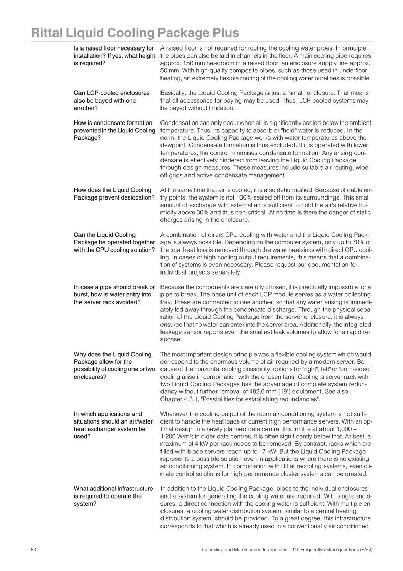
Rittal Liquid Cooling Package Plus
Is a raised floor necessary for installation? If yes, what height is required?A raised floor is not required for routing the cooling water pipes. In principle, the pipes can also be laid in channels in the floor. A main cooling pipe requires approx. 150 mm headroom in a raised floor; an enclosure supply line approx. 50 mm. With high-quality composite pipes, such as those used in underfloor heating, an extremely flexible routing of the cooling water pipelines is possible.
Can LCP-cooled enclosures also be bayed with one another?
Basically, the Liquid Cooling Package is just a "small" enclosure. That means that all accessories for baying may be used. Thus, LCP-cooled systems may be bayed without limitation.
How is condensate formation prevented in the Liquid Cooling Package?
Condensation can only occur when air is significantly cooled below the ambient temperature. Thus, its capacity to absorb or "hold" water is reduced. In the norm, the Liquid Cooling Package works with water temperatures above the dewpoint. Condensate formation is thus excluded. If it is operated with lower temperatures, the control minimises condensate formation. Any arising con-densate is effectively hindered from leaving the Liquid Cooling Package through design measures. These measures include suitable air routing, wipe-off grids and active condensate management.
How does the Liquid Cooling Package prevent desiccation?
At the same time that air is cooled, it is also dehumidified. Because of cable en-try points, the system is not 100% sealed off from its surroundings. This small amount of exchange with external air is sufficient to hold the air's relative hu-midity above 30% and thus non-critical. At no time is there the danger of static charges arising in the enclosure.
Can the Liquid Cooling Package be operated together with the CPU cooling solution?
A combination of direct CPU cooling with water and the Liquid Cooling Pack-age is always possible. Depending on the computer system, only up to 70% of the total heat loss is removed through the water heatsinks with direct CPU cool-ing. In cases of high cooling output requirements, this means that a combina-tion of systems is even necessary. Please request our documentation for individual projects separately.
In case a pipe should break or burst, how is water entry into the server rack avoided?
Because the components are carefully chosen, it is practically impossible for a pipe to break. The base unit of each LCP module serves as a water collecting tray. These are connected to one another, so that any water arising is immedi-ately led away through the condensate discharge. Through the physical sepa-ration of the Liquid Cooling Package from the server enclosure, it is always ensured that no water can enter into the server area. Additionally, the integrated leakage sensor reports even the smallest leak volumes to allow for a rapid re-sponse.
Why does the Liquid Cooling Package allow for the possibility of cooling one or two enclosures?
The most important design principle was a flexible cooling system which would correspond to the enormous volume of air required by a modern server. Be-cause of the horizontal cooling possibility, options for "right", left" or "both-sided" cooling arise in combination with the chosen fans. Cooling a server rack with two Liquid Cooling Packages has the advantage of complete system redun-dancy without further removal of 482,6 mm (19") equipment. See also Chapter 4.3.1, "Possibilities for establishing redundancies".
In which applications and situations should an air/water heat exchanger system be used?
Whenever the cooling output of the room air conditioning system is not suffi-cient to handle the heat loads of current high performance servers. With an op-timal design in a newly planned data centre, this limit is at about 1,000 –1,200 W/m²; in older data centres, it is often significantly below that. At best, a maximum of 4 kW per rack needs to be removed. By contrast, racks which are filled with blade servers reach up to 17 kW. But the Liquid Cooling Package represents a possible solution even in applications where there is no existing air conditioning system. In combination with Rittal recooling systems, even cli-mate control solutions for high performance cluster systems can be created.
What additional infrastructure is required to operate the system?
In addition to the Liquid Cooling Package, pipes to the individual enclosures and a system for generating the cooling water are required. With single enclo-sures, a direct connection with the cooling water is sufficient. With multiple en-closures, a cooling water distribution system, similar to a central heating distribution system, should be provided. To a great degree, this infrastructure corresponds to that which is already used in a conventionally air conditioned
83 Operating and Maintenance Instructions – 10 Frequently asked questions (FAQ)

Rittal Liquid Cooling Package Plus
data centre. The "cold" water is provided by water chillers (with adequate re-dundancy, especially in regard to the pumps). The water is distributed over a cooling water network in the data centre to fan coil or ceiling cooling units.What key disadvantages of today's air-cooled solutions are remedied by water cooling?
The chief problem of conventional cooling involves directing large amounts of cool air through raised floors, suspended ceilings and within the room. Often, because of complex flow conditions, the cold air does not reach the servers in sufficient quantities. There is actually enough cold produced; often, the cooling output from raised floor systems lies far above the electrically connected load of the unit, which needs to be cooled. In spite of this, the cooling is insufficient. This effect is explained by the fact that the cooling air is already warmed too much through recirculation on its way to the server. By using water to remove the heat out of the enclosure, an excellent separation between cold air and re-moved thermal energy is achieved. Because of its material characteristics, wa-ter can transport thermal energy almost 4,000 times "better" than air. Small pipes are capable of transporting very large quantities of heat.
Can accessories and other equipment from 482.6 mm (19") enclosures be used in conjunction with the Liquid Cooling Package?
The Liquid Cooling Package and the accompanying server enclosure are stan-dard products within the Rittal family of enclosures. All components and acces-sory parts can be used without limitation.
Up to what depth may servers be installed?
Modern server systems may be up to 800 mm deep. Because of that, it is rec-ommended that the 482.6 mm (19") level in the enclosure be installed so that the same distance remains to the door in front and in back. In combination with the space on the side between the 482.6 mm (19") level and the Liquid Cooling Package, sufficient room for the air which is fed or emitted is achieved. The side openings do not need to be completely open throughout their depth.
How does the Liquid Cooling Package respond to an elevated ambient temperature or fire?
Because the closed design seals the system to the outside, even greatly in-creased ambient air temperatures are not a problem – as long as the cold water supply is functioning. This represents an effective protection against the effects of fire in case of a fire in the room. Smoke, corrosive gases, water steam and fire-fighting water are securely kept away. Only extremely high temperatures or direct exposure to flames would be critical, but the consequences of fire in the area or in the adjacent room are in any case restrained.
Does the maximum depth available for installed equipment correspond with the enclosure's depth?
Almost the entire depth of the enclosure can be used for installed equipment. No other space for installed mechanical equipment, e.g. fans, is required.
84 Operating and Maintenance Instructions – 10 Frequently asked questions (FAQ)

Rittal Liquid Cooling Package Plus
11 Glossary1 U server: 1 U servers are very flat and deep, modern high performance servers, whose height corresponds to one height unit (1 U = 44.54 mm, the smallest standard height division). Typical dimensions are (W x D x H) 19" (482.6 mm) x 800 mm x 1 U. These systems normally include 2 CPUs, many GB RAM and hard drives, so that they require up to 100 m3/h cooling air at a maximum of 32°C.
482.6 mm (19") level: The front sides of the devices built into the server enclosure form the 19" (482.6 mm) level.
Blade server: By orienting dual CPU systems vertically and placing up to 14 units on a com-mon backplane to provide for signal routing and power supply, one has a so-called blade server.Blade servers can "generate" up to 4.5 kW heat loss per 7 U and 700 mm depth.
"Front to back" cooling principle:
The devices built into the server enclosure are normally cooled according to the "front to back" cooling principle. Under this cooling principle, cold air supplied by external air conditioning is blown to the front of the server enclosure. The fans in the devices built into the server enclosure direct this air horizontally through the server enclosure. The air is warmed through this process and is exhausted out the rear side of the en-closure.
Fig. 70: "Front to back" cooling principle as an example in a 1 U server
Hotspot: A hotspot is the concentration of thermal energy in a small area.Hot spots normally lead to local overheating and can cause system malfunc-tions.
Air/water heat exchanger: Air/water heat exchangers operate according to the same principle as automo-bile radiators. A liquid (water) flows through the heat exchanger, while, at the same time, air is blown over its surface area (which is as large as possible), fa-cilitating energy exchange. Depending on the temperature of the circulating liquid (water), an air/water heat exchanger may either heat or cool the circulated air.
Recooling system: As an initial comparison, a recooling system is like a refrigerator – through an active cooling circuit, unlike a household refrigerator, a recooling system pro-duces cold water. The thermal energy which is removed from the water is dis-sipated to the outside by fans. Because of this, it is normally advisable to locate recooling systems outside of buildings.Recooling systems and air/water heat exchangers form a normal cooling com-bination.
85 Operating and Maintenance Instructions – 11 Glossary

Rittal Liquid Cooling Package Plus
Switch: Multiple servers normally communicate with one another and in the network using switches.Because as many inputs as possible are located on the front side of switches, they frequently have an airflow from the side, not "front to back" cooling.
86 Operating and Maintenance Instructions – 11 Glossary

87 Operating and Maintenance Instructions – 12 Spare parts
Rittal Liquid Cooling Package Plus12 Spare parts
Tab. 14: Spare parts list – Liquid Cooling Package Plus
ItemModel No.
SKQty./Pack
Circuit board, water unit, complete 1
Circuit board, control unit, complete 1
Circuit board, fan unit, complete 1
Fan 1
Fan module, complete 1
Display 1
Heat exchanger
Sensor condensate pump 1
Float-actuated switch 1
Leakage sensor 1
Control valve 1
Flow meter 1
Condensate pump 1
Automatic bleeding valve 1
Cold air temperature sensor 1
Warm air temperature sensor 1
Temperature sensor water flow 1
Temperature sensor water return 1

88 Operating and Maintenance Instructions – 13 Accessories
Rittal Liquid Cooling Package Plus13 Accessories
13.1 Accessories Liquid Cooling Package
Tab. 15: Accessories list – Liquid Cooling Package Plus
13.2 Accessories from the rack program
Tab. 16: Accessories list – rack program
ItemModel No.
SKQty./Pack Comments
Vertical shielding (foam strips) for enclosure width 600 mm, for mounting side panel
3301.380 1
Vertical shielding (foam strips) for enclosure width 600 mm, for mounting LCP Plus
3301.370 1
Vertical shielding (foam strips)for enclosure width 800 mm, for mounting side panel
3301.390 1
Vertical shielding (foam strips)for enclosure width 800 mm, for mounting LCP Plus
3301.320 1
Covers to close off unused air entry and exhaust openings on Liquid Cooling Package
3301.310 2
Add-on cover 3301.421 1
Connection hose 3301.351 2
Connection cable, single-phase 7856.025 1 EU-Type
Connection cable, three-phase 7856.026 1 CEE plug 230 V
Item Model No. Qty./Pack Comments
Blanking plates, 1U 7151.035 2 also available in other heights!
Side panel package/side panel, screw-fastened 2000 mm x 1000 mm
8102.235 2

Rittal Liquid Cooling Package Plus
14 Further technical infor-mation
14.1 Hydrological information To avoid system damage and to ensure safe operation, Rittal GmbH & Co KG recommends the use of system water or an additive whose composition does not differ from that presented in the following summary:
Tab. 17: Hydrological data
pH value 7 – 8.5%
Carbon hardness > 3 < 8 °dH
Free carbonic acid 8 – 15 mg/dm3
Accompanying carbonic acid 8 – 15 mg/dm3
Corrosive carbonic acid 0 mg/dm3
Sulphides Free
Oxygen <10 mg/dm3
Chloride ions < 50 mg/dm3
Sulphate ions < 250 mg/dm3
Nitrates and nitrites < 10 mg/dm3
COD < 7 mg/dm3
Ammonia < 5 mg/dm3
Iron < 0.2 mg/dm3
Manganese < 0.2 mg/dm3
Conductivity < 2200 µS/cm
Residue on evapouration < 500 mg/dm3
Potassium permanganate con-sumption
< 25 mg/dm3
Suspended matter < 3 mg/dm3
> 3 < 15 mg/dm3 Partial current purification recommended> 15 mg/dm3 Continuous purification recommen-ded
89 Operating and Maintenance Instructions – 14 Further technical information

Rittal Liquid Cooling Package Plus
14.2 Characteristic curves14.2.1 Cooling output
Fig. 71: Cooling output of the Liquid Cooling Package Plus, with flow temperature 10 °C
Fig. 72: Cooling output of the Liquid Cooling Package Plus, with flow temperature 15 °C
10
15
20
25
30
35
10 15 20 25 30 35 40 45
Air admittance 20˚CAir admittance 25˚C
Inlet temperature [°C]
Coo
ling
out
put
[Wat
t]
10,00
15,00
20,00
25,00
30,00
35,00
20,0 25,0 30,0 35,0 40,0 45,0 50,0 55,0 60,0 65,0
Air admittance 20˚CAir admittance 22˚CAir admittance 25˚C
Inlet temperature [°C]
Coo
ling
out
put
[Wat
t]
90 Operating and Maintenance Instructions – 14 Further technical information

Rittal Liquid Cooling Package Plus
14.2.2 Pressure lossFig. 73: Pressure loss in the Liquid Cooling Package Plus
0
0,2
0,4
0,6
0,8
1
1,2
1,4
1,6
0 10 20 30 40 50 60 70 80Volumetric flow [l/min]
Pre
ssur
e lo
ss [
bar
]
91 Operating and Maintenance Instructions – 14 Further technical information

Rittal Liquid Cooling Package Plus
14.3 Overview diagramFig. 74: Overview diagram – Liquid Cooling Package Plus (front, side and rear views)
Fig. 75: Overview diagram – Liquid Cooling Package Plus (detail B and C)
View without side panel right front/back
Heat exchangerFront left side panel
Back left side panel
Connector
Fan mounting plate (6x)
Fan slide rail (6x)
Fan partitionFront partition
Fan slide rail connector cover (3x)
92 Operating and Maintenance Instructions – 14 Further technical information

Rittal Liquid Cooling Package Plus
Fig. 76: Overview diagram – Liquid Cooling Package Plus (isometry)
93 Operating and Maintenance Instructions – 14 Further technical information

Rittal Liquid Cooling Package Plus
14.4 Circuit diagramFig. 77: Circuit diagram
Display on front door
RJ12
K 04434 01 SK 23
Kycon KPP-3P
L3L2L1NPE
L1L2L3NPE
Mains input Fuses 3 x 6ANetzfilter / Line filter
3 x 10A
PEPEPE
RJ45
RJ45
RS232 (IOIOI)
Power 24 VDC
P-I2C
Ethernet A1CMC-TC/Basic
RJ45
M
Ethernet cable Kat. 5
Molex (Blind mating)
Temp. sensor FAN-1
B7Temp. sensor HEX-1
B6
2 x 0,34qmm
Molex (Blind mating)
Fuse 2,5 APE
PE
PE
Schirm / shield
Fan Controller 1
Molex (Blind mating)
Temp. sensor FAN-2
B7
Molex (Blind mating)
Fan Controller 2
Molex (Blind mating)
Temp. sensor FAN-3
B7
Molex (Blind mating)
Fan Controller 3
2 x 0,34qmm
2 x 0,34qmm
3 x 1,0qmm
3 x 1,0qmm
3 x 1,0qmm
4 x
0,25
qm
m
3 x
1,0q
mm
B6
B6
Temp. sensor HEX-2
Temp. sensor HEX-3
B1 Temp. sensor (water inlet)B2 Temp. sensor (water outlet)B3 Flow meterY1 Motor valveB4 Level sensor (leakage)B5 Level sensor (condensate)
3 x 1,0qmm
MPE
3 x 1,0qmm
Condensate pump
M1
A4
Fuse 0,5 A
PE
PE
Water group controller
F1...F324VDC Supply
X2X1
Z1
A2
X25
X18
X12X13X14X19X16X17
X11
X10
F4
M2
A5
X30
X29
X31
X27
MM2
X30
X29
X31
X28
MM2
X30
X29
X31
X27
MM2
X30
X29
X31
X28
MM2
X30
X29
X31
X27
MM2
X30
X29
X31
X28
X4
X6
X9X8
X26
X3
X7
X5
F5
PE
PE
PE
Schirm / shield
A5
X4
X6
X9X8
X26
X3
X7
X5
F5
PE
PE
PE
Schirm / shield
A5
X4
X6
X9X8
X26
X3
X7
X5
F5
X24
X21
X22
X23
F6Fuse 2,5 A
Fuse 2,5 A
Fuse 2,5 A
Fuse 2,5 A
Fuse 2,5 A
F6
F6
A3X32
Z2
A1 = LCP-Steuerplatine
A3 = Netzteil 24 V DC
A4 = Wasserplatine
A5 = Lüfterplatine
B1 = Temperaturfühler Wasservorlauf
F4 = Sicherung 0,5A
M1 = Pumpe
X14 = Durchflussmesser
A2 = Display
X19 = Motorventil
X1 = Eingangsstecker
X2 = Klemmleiste
X3 = AC Eingang Lüfter
X4 = Anschluss AC zum Lüfter
X8 = Temperaturfühler Ausblasluft
X9 = Temperaturfühler Ansaugluft
X10 = AC Wasserkontroller
X11 = Kondensatpumpe
X12 = Temperaturfühler Wasservorlauf
X13 = Temperaturfühler Wasserrücklauf
X21 = Anschluss DC Eingang CMC
X22 = Anschluss Steuerkabel CMC
X23 = Anschluss Ethernet
X24 = Anschluss CMC / Display
X26 = Anschluss DC Eingang Lüfter
X25 = Anschluss Display
X27 = Blind-Mating zur Lüftereinheit
X30 = Anschluss Lüfter
X18 = Anschluss DC Eingang Wasser
X16 = Leckagefühler
X32 = IEC 320 Anschluss an Netzteil A2
X17 = Kondensatfühler
F1-3 = Sicherung 6A
F5-6 = Sicherung 2,5A
X5 = Anschluss AC zum Lüfter
X28 = Blind-Mating Kabel
X29 = Blind-Mating Lüfter
X6 = Lüfter Drehzahlgeber
X7 = Lüfter Drehzahlgeber
X31 = Lüfter Sensor Hall IC
B2 = Temperaturfühler Wasserrücklauf
B3 = Durchflußmesser
B4 = Leckagefühler
B5 = Kondensatfühler
Z1 = Netzfilter, 4 polig
M2 = Lüftermotor 4stufig
B6 = Temperaturfühler HEX-1
B7 = Temperaturfühler Lüfter-1
Z2 = Ferritkern
Übersicht Kabelbaum "LCP - Plus" / Overview cable harness "LCP Plus"
Wechselstrom-Kabelbaun 230V AC / AC cable harness 230 V AC
Legende / Legend:
Gleichstrom und Kommunikationssiganel / DC and communication signals
Sensorsignal / Sensor signals
Sensor signals
AC
cab
le h
arne
ss
DC
& S
igna
l cab
le h
arne
ss
A1 = LCP control board
A3 = Power pack 24 V DC
A4 = Water board
A5 = Fan board
B5 = Condensate level sensor
F1-3 = Fuse 6A
M1 = Pump
X14 = Flow meter
A2 = Display
X19 = Motor valve
X1 = Input connector
X2 = Terminal strip
X3 = AC input fan
X4 = Connector AC to fan
X6 = Fan speed sensor
X8 = Temperature sensor extracted air
X9 = Temperature sensor air intake
X10 = AC water controller
X11 = Condensate pump
X12 = Temperature sensor water inlet
X13 = Temperature sensor water reflow
X21 = Connector DC input CMC
X22 = Connector cable CMC
X23 = Connector Ethernet
X24 = Connector CMC / display
X25 = Connector display
X26 = Connector DC input fan
X27 = Blind mating to fan unit
X30 = Connector fan
X18 = DC input water
X16 = Leakage level sensor
X17 = Condensate level sensor
F4 = Fuse 0.5A
F5-6 = Fuse 2.5A
X5 = Connector AC to fan
X7 = Fan speed sensor
X28 = Blind mating cable
X29 = Blind mating fan
X31 = Fan sensor Hall IC
B2 = Temperature sensor water reflow
B3 = Flow meter
B4 = Leakage level sensor
B1 = Temperature sensor water inlet
Z1 = Line filter, 4 poles
M2 = Fan motor 4 speeds
B7 = Temperature sensor fan-1
B6 = Temperature sensor HEX-1
X32 = IEC 320 connection to power pack A2
Z2 = Ferrite core
94 Operating and Maintenance Instructions – 14 Further technical information

Rittal Liquid Cooling Package Plus
14.5 Water circulation diagramFig. 78: Water circulation diagram1 Two-way control valve2 Leakage sensor3 Cooling water flow4 Cooling water return5 Condensate pump6 Condensate sensor (float-actuated switch)7 Flow meter8 Condensate collecting tray9 Fan module 1 (top)10 Fan module 2 (middle)11 Fan module 3 (bottom)
8 6 5 4
1 2 3
7
11
10
9
95 Operating and Maintenance Instructions – 14 Further technical information

Rittal Liquid Cooling Package Plus
Appendix 1Installation checklistRittal GmbH & Co. KG hopes that this checklist will help its customers and co-operation partners install and operate the products of the Liquid Cooling Pa-ckage family successfully.
Before the installation:
Are shut-off valves installed in the flow and return?
These valves serve to facilitate exchange or maintenance of the Liquid Cooling Package without requiring that the entire cold water supply is shut off.
Is a tacho setter installed in the return of each Liquid Cooling Package?
The tacho setter ensures a constant volumetric flow and helps to maintain the hydraulic balance of the system, especially when operating with other types of units, such as convectors.
Is a magnetic filter installed in the flow of each Liquid Cooling Package?
Rittal GmbH & Co. KG recommends that the flow of each Liquid Cooling Pa-ckage be equipped with a magnetic filter in order to protect the parts of the de-vice from malfunction due to contamination from the water system. It is recommended to install the filter as close to the Liquid Cooling Package as pos-sible.
Is the water supply area insulation carried out cleanly?
Proper insulation protects against condensate formation, especially on the parts of the cooling water flow.
Note:
If the pipework for the Liquid Cooling Package is carried out according to the Tichelmann principle, a tacho setter is not necessary.
Photo Amacell
96 Operating and Maintenance Instructions – Installation checklist
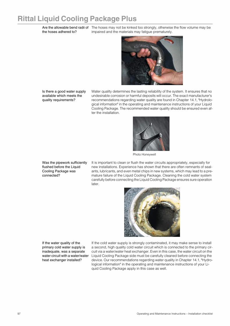
Rittal Liquid Cooling Package Plus
Are the allowable bend radii of the hoses adhered to?The hoses may not be kinked too strongly, otherwise the flow volume may be impaired and the materials may fatigue prematurely.
Is there a good water supply available which meets the quality requirements?
Water quality determines the lasting reliability of the system. It ensures that no undesirable corrosion or harmful deposits will occur. The exact manufacturer's recommendations regarding water quality are found in Chapter 14.1, "Hydrolo-gical information" in the operating and maintenance instructions of your Liquid Cooling Package. The recommended water quality should be ensured even af-ter the installation.
Was the pipework sufficiently flushed before the Liquid Cooling Package was connected?
It is important to clean or flush the water circuits appropriately, especially for new installations. Experience has shown that there are often remnants of seal-ants, lubricants, and even metal chips in new systems, which may lead to a pre-mature failure of the Liquid Cooling Package. Cleaning the cold water system carefully before connecting the Liquid Cooling Package ensures sure operation later.
If the water quality of the primary cold water supply is inadequate, was a separate water circuit with a water/water heat exchanger installed?
If the cold water supply is strongly contaminated, it may make sense to install a second, high quality cold water circuit which is connected to the primary cir-cuit via a water/water heat exchanger. Even in this case, the water circuit on the Liquid Cooling Package side must be carefully cleaned before connecting the device. Our recommendations regarding water quality in Chapter 14.1, "Hydro-logical information" in the operating and maintenance instructions of your Li-quid Cooling Package apply in this case as well.
Photo Honeywell
97 Operating and Maintenance Instructions – Installation checklist

Rittal Liquid Cooling Package Plus
Was the water prepared/treated with the appropriate additives?In addition to our recommendations regarding water quality, we recommend that the water be enriched with corrosion inhibitor and/or antifreeze. Also, a treatment to prevent algae and biofilms may be expedient in some cases.
Are unused height units in the bayed server enclosures sealed through vertical blanking plates, and are the side vertical foam strips installed?
In order to prevent undesired air short circuits and circulation patterns inside the server enclosure, all unused height units of the 482.6 mm (19") level should be closed off with blanking plates. Thus, the air will only enter the rear side of the server enclosure through the server itself, where it is drawn off by the Liquid Cooling Package. The blanking plates are available in various heights, e.g. Mo-del No. SK 1931.200 for one height unit. The vertical foam sealing strips, which are installed on the side in the server enclosure, ensure that the cooled air does not flow on the sides, past the 482.6 mm (19") level. Sealing strips are available for 2 applications and 2 enclosure widths. The respective model numbers are found in Chapter 13, "Accessories" in the operating and maintenance instruc-tions of your Liquid Cooling Package
Are all electrical, water, and power connections correctly made?
Before water is admitted, and, ideally before the ball valves are opened, be sure to check that all connections are properly made. Pay special attention to check that all quick release fasteners are fully snapped into place.
Is the TS/PS server enclosure equipped with the appropriate door?
Both the Liquid Cooling Package Standard and the Liquid Cooling Package Plus function with a sealed air circuit. Thus, the cooled server enclosure must largely be hermetically sealed and equipped with unperforated steel or glass doors on the front and rear sides.
Exception when using the Liquid Cooling Package Extend:The front of the server enclosure must, in this case, be fully air permeable.
After admitting cold water:
Are all parts and connections water tight?
Please check to be sure that all parts and connections which carry water are water tight. The Liquid Cooling Package is subject to an individual, comprehen-sive factory test, which also includes checking for leaks. This additional check serves to locate problems, such as possible transport damage, and to prevent greater damage.
Venting of the Liquid Cooling Package Plus
The Liquid Cooling Package Plus has an automatic vent. This has been closed in the factory and must be opened for venting purposes during initial startup. Close the vent again after startup. To gain access to the vent, the top fan must be removed.
Photo Clariant
98 Operating and Maintenance Instructions – Installation checklist

Rittal Liquid Cooling Package Plus
After installation:We recommend that the following selected parameters be gathered and docu-mented within a short time after installation.
- Inlet temperature
- Return temperature
- Volumetric flow with opened magnetic valve
Please feel free to contact Rittal if you have further questions or problems:
For malfunctions and repairs
Rittal Service Department
Tel.: +49 (0) 27 72/50 5-18 55E-mail: [email protected]
Note:
Documenting these parameters helps with error analysis if, during operati-on, malfunctions occur.
99 Operating and Maintenance Instructions – Installation checklist

100 Operating and Maintenance Instructions – Preparation and maintenance of the water in recooling systems
Rittal Liquid Cooling Package PlusAppendix 2Preparation and maintenance of the water in recooling systems
Depending on the type of installation to be cooled, certain purity requirements are placed on the cooling water in a recooling system. According to the level of contamination and the size and design of the recooling systems, a suitable pro-cess is used to prepare and/or maintain the water. The most common types of contamination and frequently used techniques to eliminate them in industrial cooling are:
Tab. 18: Cooling water contaminants and treatment procedures
Type of impurity Procedure
Mechanical contamination Filter the water using:Mesh filter, sand filter, cartridge filter, precoated filter, magnetic filter
Excessive hardness Soften the water via ion exchange
Moderate content of mechani-cal contaminants and harde-ners
Treat the water with stabilisers and/or dispersing agents
Moderate content of chemical contaminants
Treat the water with passivators and/or inhibitors
Biological contaminants, slime bacteria and algae
Treat the water with biocides
Note:
For the proper operation of a recooling system that uses water on at least one side, the composition of any additive used or system water should not deviate substantially from hydrological data presented in Chapter 14.1, "Hy-drological information".