Liquid Coatings for Girthwelds and Joints - … · the use of liquid epox-ies and liquid urethanes...
15
nvironmental and cost constraint issues drive the use of liquid epox- ies and liquid urethanes for the protec- tion of girthwelds and joints on pipelines. This article will use case histories to illustrate the field application of ure- thane and epoxy liquid coatings on girthwelds and appurtenances. Rehabilitation projects provide the backbone of the article. Specific requirements of liquid coatings and performance characteristics are included. The article also discusses why the use of liquid coatings is increasing and spells out the steps for their application. 22 www.paintsquare.com JPCL / August 2006 / PCE Why Liquid Coatings? An advantage of using liquid coatings in the place of FBE on girthwelds and joints on pipelines is that, unlike FBE or other powder coatings, under most con- ditions, liquid coatings do not require extra heat to achieve cure. On-site field application is therefore simplified because only cleaning and application equipment are needed. 1,2 Recent devel- opments in chemistry and technology have led to liquid coatings with perform- ance characteristics that approach those of FBE coatings (Table 1). Fitness for Use Two types of information help deter- mine whether or not a coating system is fit for use on a given project. Testing the performance and properties of the system is one source. The other source is performance history of the system in an exposure environment similar to what will be encounted in the upcom- ing project. Therefore, the first case history in this article reports on the long-term performance of liquid coat- ings on an underground storage tank. Subsequent cases in the article will report on the performance of similar coatings on pipelines in underground service. Case History: Underground Tanks in Italy For protection of steel tanks for under- ground service, the end user originally planned to prime the steel tanks and Liquid Coatings for Girthwelds and Joints: By J.A. Kehr, 3M USA; R. Hislop, 3M UK; P. Anzalone, 3M Italy; and A. Kataev, 3M Russia Proven Corrosion Protection for Pipelines Editor’s Note: This article was presented at the 16th International Conference on Pipeline Protection in Paphos, Cyprus, November 2–4, 2005, and is published in the conference Proceedings. Test/Property Cathodic disbondment resistance– 14 days, 65 C, 1.5 V, mmr Impact – ASTM G-14 16 mm tup, 24 C Material cost per unit volume Moisture vapor transmission 3 Time to backfill – minutes @ 24 C FBE-Single Layer 4.3 2.4 X 1.8 – Liquid Epoxy 6.5 2.8 3.1X 1.8 160 Liquid Urethane 9 3.2 2.6X 4.3 30 Table 1: Performance Properties of Rehab Coatings
Transcript of Liquid Coatings for Girthwelds and Joints - … · the use of liquid epox-ies and liquid urethanes...

nvironmental and costconstraint issues drivethe use of liquid epox-
ies and liquid urethanes for the protec-tion of girthwelds and joints onpipelines.
This article will use case histories toillustrate the field application of ure-thane and epoxy liquid coatings ongirthwelds and appurtenances.Rehabilitation projects provide thebackbone of the article. Specificrequirements of liquid coatings andperformance characteristics areincluded. The article also discusseswhy the use of liquid coatings isincreasing and spells out the steps fortheir application.
22 www.paintsquare.comJ P C L / A u g u s t 2 0 0 6 / P C E
Why Liquid Coatings?An advantage of using liquid coatings inthe place of FBE on girthwelds andjoints on pipelines is that, unlike FBE orother powder coatings, under most con-ditions, liquid coatings do not requireextra heat to achieve cure. On-site fieldapplication is therefore simplifiedbecause only cleaning and applicationequipment are needed.1,2 Recent devel-opments in chemistry and technologyhave led to liquid coatings with perform-ance characteristics that approach thoseof FBE coatings (Table 1).
Fitness for Use Two types of information help deter-mine whether or not a coating systemis fit for use on a given project. Testing
the performance and properties of thesystem is one source. The other sourceis performance history of the system inan exposure environment similar towhat will be encounted in the upcom-ing project. Therefore, the first casehistory in this article reports on thelong-term performance of liquid coat-ings on an underground storage tank.Subsequent cases in the article willreport on the performance of similarcoatings on pipelines in undergroundservice.
Case History: Underground Tanks in ItalyFor protection of steel tanks for under-ground service, the end user originallyplanned to prime the steel tanks and
Liquid Coatings for Girthwelds
and Joints:
By J.A. Kehr, 3M USA; R. Hislop, 3M UK; P. Anzalone, 3M Italy; and A. Kataev, 3M Russia
Proven Corrosion Protection for Pipelines
Editor’s Note: This article was presented at the 16th InternationalConference on Pipeline Protection in Paphos, Cyprus, November 2–4,2005, and is published in the conference Proceedings.
Test/PropertyCathodic disbondment resistance–14 days, 65 C, 1.5 V, mmrImpact – ASTM G-1416 mm tup, 24 CMaterial cost per unit volumeMoisture vapor transmission3
Time to backfill – minutes @ 24 C
FBE-Single Layer4.3
2.4
X1.8–
Liquid Epoxy6.5
2.8
3.1X1.8160
Liquid Urethane9
3.2
2.6X4.330
Table 1: Performance Properties of Rehab Coatings

apply a polyethylene (PE) tape as thecorrosion coating. During trials, theapplication process took several days,and during that time, exposure to thesun caused the tape to disbond. Inaddition, wrinkling was a problem, aswas application to irregularly shapedareas. Follow-up trials showed that atwo-part liquid epoxy was a viablesolution. Based on technical4 and appli-cation factors, a material was selected,and the tanks were coated. The tankswere transported 300 km, installed,and buried. This project was done in1992.
Monitoring of the cathodic protec-tion indicated that the coating was per-forming satisfactorily after 13 years.In April 2005, a support wall col-lapsed, allowing an opportunity forvisual inspection of the coating (Fig. 1).All parties were satisfied with thecoating performance.
Five years after the first tanks werecoated, a second set of tanks was coatedwith an epoxy-tar material and installed.An inspection in April 2005 revealedsevere disbonding of the coating.
While the project above is a specificcase history that shows that liquidcoatings can perform well, it also illus-trates the importance of material selec-
tion and/or application. Liquid coat-ings have a track record of more than40 years of performance in pipeline orsimilar underground situations.
Application Principles of Liquid Coatings
The application process for liquid coat-ings consists of simple steps—cleaningthe substrate, applying the coatingmaterial, and allowing the coating tocure. Although the process is simple,details of each step are important.
Cleaning the SubstrateFirst, foreign materials, e.g., old coat-ing, dirt, oil, and grease, should beremoved. Sharp edges should be
23www.paintsquare.com J P C L / A u g u s t 2 0 0 6 / P C E
ground to approximately a 3 mmradius, and weld spatter should beremoved with chipping hammers, files,or grinding wheels. Next, the areashould be blast cleaned to an accept-able standard such as NACE No.2/SSPC-SP 10, Near-White BlastCleaning.5 Blast cleaning can be per-formed with automated equipment(Fig. 2A) or by hand (Fig. 2B).
Blast cleaning also establishes ananchor pattern or surface roughness.Typical specifications call for a surfaceprofile depth of 40 to 100 µm.Angular media, such as inorganic min-erals or hardened steel grit, readilyprovide a profile depth in that range.Selection and testing of the specificblast media are important. Merelyestablishing a specified profile depth orpeak count does not assure that thethe coating will perform well.
Removing inorganic salts from thesteel surface is critical. Many stan-dards call for reblasting if rust bloomoccurs. If rust bloom occurs within afew hours of blast cleaning, it indicatesthe presence of salt on the steel. Blastcleaning alone is normally insufficientto remove salt. A water or acid washmay be required after blasting orbetween blast steps.
To prevent the blast cleaning processitself from contaminating the steel,condensate traps should be used toremove potential contaminants—oiland water—from the compressed air
Fig. 1: Underground Tanks in Italy
Fig. 2: Cleaning the Substrate
A B
Photos courtesy of the authors

ing, thus reducing the probability oferror. There is less handling of thecoating material, which reduces therisk of skin contact, but spray opera-tions require respiratory protection forworkers. Manual spray is generallyfaster than hand application.
Spray-grade coatings are designed toreact faster than hand-applied coatings,reducing the probability of contamina-tion from flying debris or insects. Theprocess is well-suited to large or irreg-ularly shaped objects.• Automated spray: Automatic sprayapplication requires specialized fit-for-purpose equipment (Fig. 3B). It usesproportioning equipment similar to thetype used in manual spray operation.Automated spray is usually suitablefor uniformly mixed and shapedobjects, such as girthwelds for pipelinecoating rehabilitation. It providesgreater control over coating thicknessand uniformity, thereby saving materi-al. This approach requires more set-uptime, but can be much faster than handor manual spray application.
Coating CureThe time required for a coating to geland cure depends on the specific mate-rial, the temperature of the steel, andthe atmospheric conditions. Urethanescan be designed to cure faster and atlower temperatures than epoxies.
The manufacturer’s data sheet will
that powers the blast cleaning system.After blasting, residual dust should beremoved either by vacuum or by blow-ing down the steel with clean com-pressed air.
The blast process also roughens andfeathers the factory-applied coating.
ApplicationWith 100% solids materials, there arethree methods of application—hand(brush, roller, or squeegee), manualspray, and automated spray. Eachapplication technique has its advan-tages and disadvantages.• Hand application: Hand applicationdepends on the skill of the operator inboth premixing and application. Theprocess is slower than manual or auto-mated spray, is more labor intensive,and brings the operators into closercontact with the coating material—thusincreasing the risk of exposure if prop-er protective/respiratory equipment isnot used. Because hand application is aslower process, slow-cure materials aretypically used to increase the pot life.That means a longer cure time beforeburial or handling. Hand application iseffective for small coating projects.• Spray application: Without the addi-tion of solvent, manual spray applica-tion requires the use of plural-compo-nent spray systems (Fig. 3A). Thesesystems are designed to properly pro-portion the two-component liquid coat-
give the lowest and highest allowablecure temperatures. If the steel orambient temperature is below thecure range of the specific coating, themanufacturer’s instructions for reheat-ing the steel part should be followed.Without specific instructions from thecoating or material manufacturer, agood starting point to ensure cure isto heat the part to about 65 C (18 F) ifthe ambient temperature is between-10 C (14 F) and 10 C (50 F). If thetemperature is below -10 C, the partshould be preheated to about 90 C(194 F).
If the temperature of the steel partis above 90 C (194 F), then care mustbe taken in applying the coatings toprevent volatilization of coating com-ponents. One way to avoid the prob-lem is to first apply a thin layer of thecoating (250 µm or less) and allow itto gel before applying the remainderof the coating to attain the specifiedthickness.
Liquid Coatings for Girthweld Protection
Over one million girthwelds havebeen coated with liquid materials inenvironments ranging from the trop-ics to arid deserts8 to the frigid plainsof Russia. While two-part liquid coat-ings have a long track record of per-formance on steel and as girthweldcoatings for FBE, only in the past fewyears have they been used for girth-welds for PE and polypropylene (PP)three-layer pipe coatings. The criticalissue is adhesion to the polyolefinmaterial.
Adhesion TestingTo determine the achievable bond,adhesion tests were conducted recent-ly on a urethane applied to PP. The PPsurface was abraded during blastcleaning and thermally oxidized witha gas flame before the coating applica-tion. Pull-off adhesion ranged from12.2 to 13.2 MPa for four tests.9 In all
24 www.paintsquare.comJ P C L / A u g u s t 2 0 0 6 / P C E
Fig. 3: Examples of Coating Application Methods
3A 3B

cases, the failure was in the glue, not inthe urethane or the PP, or at the inter-face between the two.
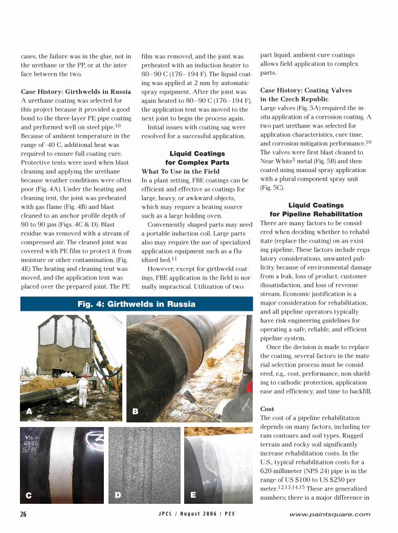
Case History: Girthwelds in RussiaA urethane coating was selected forthis project because it provided a goodbond to the three-layer PE pipe coatingand performed well on steel pipe.10
Because of ambient temperature in therange of -40 C, additional heat wasrequired to ensure full coating cure.Protective tents were used when blastcleaning and applying the urethanebecause weather conditions were oftenpoor (Fig. 4A). Under the heating andcleaning tent, the joint was preheatedwith gas flame (Fig. 4B) and blastcleaned to an anchor profile depth of80 to 90 µm (Figs. 4C & D). Blastresidue was removed with a stream ofcompressed air. The cleaned joint wascovered with PE film to protect it frommoisture or other contamination. (Fig.4E) The heating and cleaning tent wasmoved, and the application tent wasplaced over the prepared joint. The PE
film was removed, and the joint waspreheated with an induction heater to80–90 C (176–194 F). The liquid coat-ing was applied at 2 mm by automaticspray equipment. After the joint wasagain heated to 80–90 C (176–194 F),the application tent was moved to thenext joint to begin the process again.
Initial issues with coating sag wereresolved for a successful application.
Liquid Coatings for Complex Parts
What To Use in the FieldIn a plant setting, FBE coatings can beefficient and effective as coatings forlarge, heavy, or awkward objects,which may require a heating sourcesuch as a large holding oven.
Conveniently shaped parts may needa portable induction coil. Large partsalso may require the use of specializedapplication equipment such as a flu-idized bed.11
However, except for girthweld coat-ings, FBE application in the field is nor-mally impractical. Utilization of two-
part liquid, ambient-cure coatingsallows field application to complexparts.
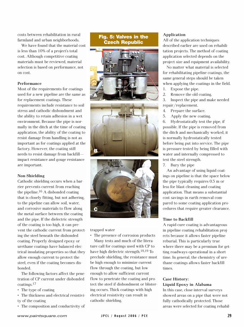
Case History: Coating Valves in the Czech RepublicLarge valves (Fig. 5A) required the in-situ application of a corrosion coating. Atwo-part urethane was selected forapplication characteristics, cure time,and corrosion-mitigation performance.10
The valves were first blast cleaned toNear-White5 metal (Fig. 5B) and thencoated using manual spray applicationwith a plural-component spray unit (Fig. 5C).
Liquid Coatings for Pipeline Rehabilitation
There are many factors to be consid-ered when deciding whether to rehabil-itate (replace the coating) on an exist-ing pipeline. These factors include regu-latory considerations, unwanted pub-licity because of environmental damagefrom a leak, loss of product, customerdissatisfaction, and loss of revenuestream. Economic justification is amajor consideration for rehabilitation,and all pipeline operators typicallyhave risk engineering guidelines foroperating a safe, reliable, and efficientpipeline system.
Once the decision is made to replacethe coating, several factors in the mate-rial selection process must be consid-ered, e.g., cost, performance, non-shield-ing to cathodic protection, applicationease and efficiency, and time to backfill.
CostThe cost of a pipeline rehabilitationdepends on many factors, including ter-rain contours and soil types. Ruggedterrain and rocky soil significantlyincrease rehabilitation costs. In theU.S., typical rehabilitation costs for a620-millimeter (NPS 24) pipe is in therange of US $100 to US $250 permeter.12,13,14,15 These are generalizednumbers; there is a major difference in
26 www.paintsquare.comJ P C L / A u g u s t 2 0 0 6 / P C E
Fig. 4: Girthwelds in Russia
B
C D E
A
costs between rehabilitation in ruralfarmland and urban neighborhoods.
We have found that the material costis less than 10% of a project’s totalcost. Although competitive coatingmaterials must be reviewed, materialselection is based on performance, noton cost.
PerformanceMost of the requirements for coatingsused for a new pipeline are the same asfor replacement coatings. Theserequirements include resistance to soilstress and cathodic disbondment andthe ability to retain adhesion in a wetenvironment. Because the pipe is nor-mally in the ditch at the time of coatingapplication, the ability of the coating toresist damage from handling is not asimportant as for coatings applied at thefactory. However, the coating stillneeds to resist damage from backfill—impact resistance and gouge resistanceare important.
Non-ShieldingCathodic shielding occurs when a bar-rier prevents current from reachingthe pipeline.16 A disbonded coatingthat is closely fitting, but not adhering,to the pipeline can allow soil, water,and corrosive materials to flow alongthe metal surface between the coatingand the pipe. If the dielectric strengthof the coating is too high, it can pre-vent the cathodic current from protect-ing the steel beneath the disbondedcoating. Properly designed epoxy orurethane coatings have balanced elec-trical insulating properties so that theyallow enough current to protect thesteel, even if the coating becomes dis-bonded.
The following factors affect the pene-tration of CP current under disbondedcoatings.17
• The type of coating• The thickness and electrical resistivi-ty of the coating• The composition and conductivity of
trapped water • The presence of corrosion products
Many tests and much of the litera-ture call for coatings used with CP tohave high dielectric strength.18,19 Topreclude shielding, the resistance mustbe high enough to minimize currentflow through the coating, but lowenough to allow sufficient currentflow to penetrate the coating and pro-tect the steel if disbondment or blister-ing occurs. Thick coatings with highelectrical resistivity can result incathodic shielding.
ApplicationAll of the application techniquesdescribed earlier are used on rehabili-tation projects. The method of coatingapplication selected depends on theproject size and equipment availability.
No matter what material is selectedfor rehabilitating pipeline coatings, thesame general steps should be takenwhen applying the coatings in the field.1. Expose the pipe.2. Remove the old coating.3. Inspect the pipe and make neededrepair/replacement.4. Prepare the surface.5. Apply the new coating.6. Hydrostatically test the pipe, ifpossible. If the pipe is removed fromthe ditch and mechanically worked, itis normally hydrostatically testedbefore being put into service. The pipeis pressure tested by being filled withwater and internally compressed totest the steel strength.7. Bury the pipe
An advantage of using liquid coat-ings on pipeline is that the space belowthe pipe typically requires 0.5 m orless for blast cleaning and coatingapplication. That means a substantialcost savings in earth removal com-pared to some coating application pro-cedures that require greater clearance.
Time to BackfillA rapid-cure coating is advantageousin pipeline coating rehabilitation proj-ects because it allows faster pipelinereburial. This is particularly truewhere there may be a premium for get-ting roadways operational in a shorttime. In general, the chemistry of ure-thane coatings allows faster backfilltimes.
Case History: Liquid Epoxy in Alabama In this case, close-interval surveysshowed areas on a pipe that were notfully cathodically protected. Thoseareas were selected for coating rehabil-
29www.paintsquare.com J P C L / A u g u s t 2 0 0 6 / P C E
Fig. 5: Valves in the Czech Republic
A
C
B
itation. The old coating was removedby a high-pressure wash; the pipelinewas abrasive blast cleaned; and a two-part liquid epoxy was manually sprayapplied.20 The application processwent well and resulted in a good-look-ing coating (Figs. 6A–D). The only con-cern was the amount of time requiredto achieve the specified cleaning stan-dard, because it increased the timerequired for the coating operation to becompleted.
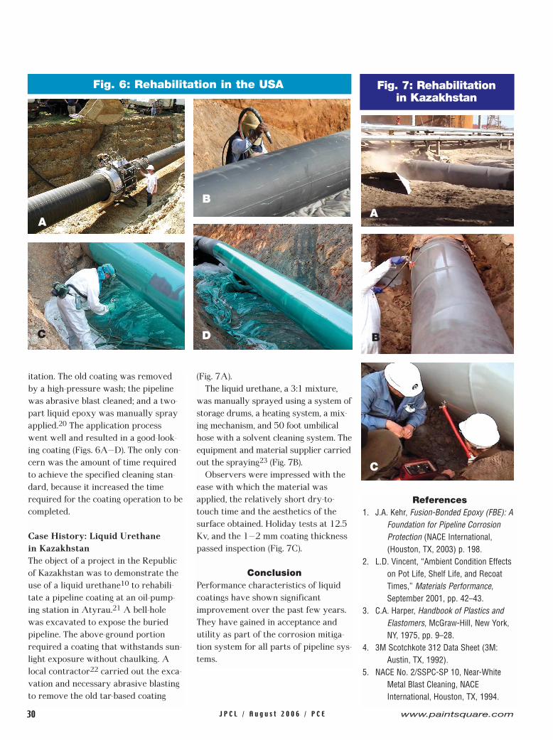
Case History: Liquid Urethane in KazakhstanThe object of a project in the Republicof Kazakhstan was to demonstrate theuse of a liquid urethane10 to rehabili-tate a pipeline coating at an oil-pump-ing station in Atyrau.21 A bell-holewas excavated to expose the buriedpipeline. The above-ground portionrequired a coating that withstands sun-light exposure without chaulking. Alocal contractor22 carried out the exca-vation and necessary abrasive blastingto remove the old tar-based coating
(Fig. 7A).The liquid urethane, a 3:1 mixture,
was manually sprayed using a system ofstorage drums, a heating system, a mix-ing mechanism, and 50 foot umbilicalhose with a solvent cleaning system. Theequipment and material supplier carriedout the spraying23 (Fig. 7B).
Observers were impressed with theease with which the material wasapplied, the relatively short dry-to-touch time and the aesthetics of thesurface obtained. Holiday tests at 12.5Kv, and the 1–2 mm coating thicknesspassed inspection (Fig. 7C).
ConclusionPerformance characteristics of liquidcoatings have shown significantimprovement over the past few years.They have gained in acceptance andutility as part of the corrosion mitiga-tion system for all parts of pipeline sys-tems.
References1. J.A. Kehr, Fusion-Bonded Epoxy (FBE): A
Foundation for Pipeline Corrosion Protection (NACE International, (Houston, TX, 2003) p. 198.
2. L.D. Vincent, “Ambient Condition Effects on Pot Life, Shelf Life, and Recoat Times,” Materials Performance, September 2001, pp. 42–43.
3. C.A. Harper, Handbook of Plastics and Elastomers, McGraw-Hill, New York, NY, 1975, pp. 9–28.
4. 3M Scotchkote 312 Data Sheet (3M: Austin, TX, 1992).
5. NACE No. 2/SSPC-SP 10, Near-White Metal Blast Cleaning, NACE International, Houston, TX, 1994.
Fig. 6: Rehabilitation in the USA
30 www.paintsquare.comJ P C L / A u g u s t 2 0 0 6 / P C E
Fig. 7: Rehabilitation in Kazakhstan
AA
B
C
B
C D


32 www.paintsquare.comJ P C L / A u g u s t 2 0 0 6 / P C E
6. Comparison of MCL Application Techniques (Burnley, UK: PIH, 2005).
7. Nova Gas Transmission Ltd., “Coating Application Procedure for Coating Girth Welds with Liquid Coatings (CAP-4),” December 1998.
8. Multi-Component Liquid Coatings vs. Heat Shrink Sleeves for PE Coated
Field Joints (Burnley, UK: PIH, 2005).9. D. Jackson, PIH, Personal Communication
(email to A. Kehr), May 27, 2005.10. 3M Skotchkote 352 UrethaneCoating
System Data Sheet and Application Instructions (3M: Austin, TX, 2001).
11. J.A. Kehr, Fusion-Bonded Epoxy (FBE): A Foundation for Pipeline Corrosion
Protection (NACE International, Houston, TX, 2003), pp. 167–197.
12. M. Dabiri, “Experiences of the Pipeline Owner,” Field Applied Coatings Seminar (Houston, TX: eb. Pipe Coating, Inc., April 29, 2003).
13. R. John, “Recoating a 42” Diameter, In-Service Oil Pipeline in the Middle East,” Pipeline Protection, ed.: J. Duncan, D. Norman, BHR 15th
International Conference on Pipeline Protection, (BHR Group: London 2001), pp. 41–46.
14. S.A. Taylor, personal interview, October 1997.
15. A.F. Bird, “Corrosion Detection Interpretation and Repairs of Carbon Steel Pipeline Utilizing Information Generated by an Ultrasonic Intelligent Vehicle,” paper No. 01634, Corrosion 2001(NACE International: Houston, TX, 2001).
16. J.A. Kehr, Fusion-Bonded Epoxy (FBE): A Foundation for Pipeline Corrosion Protection (NACE International, Houston, TX, 2003), pp. 470–471.
17. T.R. Jack, G. Van Boven, J. Wilmott, R.L.Sutherby, R.G. Worthingham, “Cathodic Protection Potential Penetration Under Disbonded Coatings,” Materials Performance(August 1994), pp. 17–21.
18. R.N. Sloan, “Pipeline Coatings,” A.W. Peabody, R.L. Bianchetti, eds., Control of Pipeline Corrosion, 2nd
Edition, (NACE International: Houston, TX, 2001), pp. 7–20.
19. C.G. Munger, Louis D. Vincent, Corrosion Protection by Protective Coatings, 2nd Edition, (NACE International: Houston, TX, 1999), p. 319.
20. 3M Scotchkote 323/323i Liquid Epoxy Coatings Data Sheet and Application Instructions (3M: Austin, TX, 2000).
21. KazTransOil, oil pumping station, Atyrau, Kazakhstan.
22. KazStroyService, Engineering Contractor,Head office, Almaty, Kazakhstan.
23. 3M USA, Austin, TX, 2000.
Clic
k ou
r Rea
der e
-Car
d at
pai
ntsq
uare
.com

moved to the Electronics/Electrical SalesDepartment. In 1992, Mr. Anzalone becamepart of 3M’s Corrosion Protection Products(CPP) Department, and he is presently 3M’sCPP South Europe sales & marketing opera-tions manager. Mr. Anzalone is a member ofUNI, ECISS, and ISO technical committees.
Alexey Kataev issales and mar-keting manager,Oil and GasProducts in 3M’sMoscow, Russia,location. Mr.Kataev has aPh.D. in polymerchemistry fromMoscow State
University. He has worked in 3M’s SpecialtyMaterials Division, Corrosion ProtectionProducts since 1993.
obtained an MBA(with distinction).Mr. Hislop had hisown company for8 years whileworking with theOffshore HSE, andconsulting on var-ious products. Hejoined 3MCorrosion
Production Products (CPP) in 1999 as north-ern european sales manager.
Pio Anzalonereceived a Ph.D.in electronics(bio-engineering)at NaplesUniversity. Hejoined 3MCompany’s JointCopying TechDepartment in1973. In 1980, he
Alan Kehr, techni-cal marketing man-ager of pipelinecoatings for 3M,has 38 years ofexperience in thepipeline and rein-forcing steel coat-ings industriesincluding researchand development
of coatings, marketing, and technical service.Mr. Kehr earned his BS in chemistry from theUniversity of Nebraska and and MBA from theUniversity of Texas-Austin. He authoredFusion-Bonded Epoxy (FBE): A Foundation forPipeline Corrosion Protection. He is active inNACE, ASTM, API, and CRSI.
Ray Hislop, graduated as a mechanical engi-neer and worked as a design & developmentengineer on diesel engines. During the devel-opment of the North Sea oil and gas fields hewas involved in technical sales of a range ofoffshore E&P products. During this period he
Click our Reader e-Card at paintsquare.com


32 www.paintsquare.comJ P C L / A u g u s t 2 0 0 6 / P C E

33www.paintsquare.com J P C L / A u g u s t 2 0 0 6 / P C E