Linius® - Kvalitetsmarkiser
88
Linius® Continuous louvre system
Transcript of Linius® - Kvalitetsmarkiser

Linius®Continuous louvre system

Table of contents < Introduction
Introduction
Table of contents 2
RENSON® company profile 3
References 4
Purpose of the CLS 7
Overview 8
Blade types
L.033 12
L.033 Variations 14
L.050 18
L.050HF 20
L.050W / L.050WS 22
L.050CL 24
L.050IM1 25
L.060HF 26
L.066 28
L.066CL 30
L.066IM1 31
L.066V 32
L.075 34
L.095 36
L.120 38
L.065AL / L.065 GL / L.065STS 40
L.060AC 42
L.150ACS / L.170ACS /
L.150ACL / L.170ACL 44
L.150DAC / L.170DAC 46
L.066P 48
Aesthetic blades for cladding
sunprotection 50
Sunclips® Evo 51
Selection criteria 52
Water penetration test
(or HEVAC tests) - principle 54
Overview table 56
Supporting structures 58
LD.0065 59
LD.0195 60
LD.0240 61
LD.0440 62
LD.0460 63
LD.0995 64
LD.1250 65
Sunclips® support structure
SD.014 / SD.054 / SD.100 66
System depth 67
Fixing elements
Fixing brackets
LZ.4202 and LZ.4211 68
U-shape mounting bracket LZ.4210 69
Angle bracket
Type LZ.4203 and LZ.4209 69
Accessories
A. Mesh 70
B. Sills 72
C. Aluminium frames 73
D. Doors 75
Specialities
A. Linius®-cassette system 77
B. Curved blades 78
C. Stand alone support structures 79
D. Acoustic applications 79
E. Mitred corners 80
F. Special shapes 81
G. Block blades L.033 and L.050 81
H. Turrets 82
I. Louvre grilles 82
J. Aesthetic façade cladding with
Sunclips® and Icarus® blades 83
Storage and maintenance
Care of equipment and materials 83
General instructions 84
Summary of RENSON® Linius®
continuous louvre system specifications 86
References 87
Contents

6 good reasons to have RENSON® as a partner.
1. Customer satisfaction by personal contact, professional advice, excellent
service and reliable, high-performance products are the main aims of our
company.
2. RENSON® is a reputable and established multinational company with
international expertise and experience thanks to the efforts of our local
specialists. They are present in all regions of the world. RENSON has assisted
with projects across the whole world, from Moscow to Tahiti and from Monaco
to Shanghai.
3. A complete service from start to finish, effective support and advice during the
design phase, site meetings and installation.
4. The production process is fully vertically integrated enabling manufacturing
to the strictest of standards. Investments in injection moulding machinery,
anodising facilities and a fully automatic powder coating installation ensure
efficiency and accuracy.
5. Continuous research and development translates customer needs into unique
solutions and innovative products.
6. RENSON® specialises in all aspects of ventilation and solar shading to achieve
the current goals of the Healthy Building Concept®.
RENSON® company profile

4
References < Introduction
Worldwide reference list
BELGIUM
Madou Tower – Brussels
Hogeschool GroepT – Leuven
Airport – Zaventem
Smithkline Beecham plant – Brussels
Alcatel building - Antwerp
Private house /office – Menen
Private residence – Bruges
Brandweerkazerne - Oudenaarde
Hospitalier Regional du Val de Sambre -
Auvelais
Secure Link - Wommelgem
Atlantis - Sint-Agatha-Berchem
FRANCE
Futuroscope - Poitiers
Euralille - Rijsel
Paris-Expo - Parijs
UVE - Rouen
Gemey Maybelline - Orléans
(Arch : Alain Bailly - Lionel Colson, Paris)
Siège SNCF - Mouchotte, Paris
CHU - Perpignan
Ifremer - Sète
Thomson - Rousset
Inria - Rennes
Institut Regional de Readapton - Nancy
I.R.R. Louis Pierquin - Nancy
Aérogare - Brest
Hospital Centre – Cannes
Palazzo delle esposizioni - Monaco
La goutte d’eau - Bègles
Centre hospitalier - Libourne
GERMANY
AIRBUS - Hamburg
Luchthaven - Frankfurt
Messehalle - Frankfurt
VW Design - Potsdam
Audi - Neckarsulm
Government quarter - Erfurt
Technology Centre - Gelsenkirchen
Peek & Cloppenburg - Cologne
Parking - Rostock
Technology Centre – Heidelberg
Wilmersdorf Arcades - Berlin
LSG Sky Chefs - Frankfurt
Elbe Shopping Centre - Hamburg
Erlangen Arcades - Erlangen
Frauenhof Institute - Magdeburg
Labour Agency – Berlin-Central
O2 World Arena - Berlin
EEZ Hamburg - Hamburg
Solon AG - Berlin
Bürohaus Scharnhausen - Ostfildern
America Center - Hamburg
Glückaufhaus - Essen
Messehalle - Frankfurt
Tempelhofer Hafen - Berlin
Kaufzentrum - Marl
Debeka Versicherung - Koblenz
Spree Dreieck - Berlin
ISRAEL
Telephone company – Naharia
HUNGARY
Vodafone – Budapest
NBC-Building – Budapest
Millenium Towers - Budapest
ITALY
University – Bologna
Parkhaus Köstlan - Brixen/Bressanone
Südtirol
POLAND
Riviera - Warszawa
Reform Plaza - Warszawa
Metro - Warszawa
Hotel Mercure - Poznan
Galeria Kazimierz - Kraków
Marino Shopping Center - Wroclaw
Promag SA - Poznan
NEDERLAND
Bouwhuis - Zoetermeer
HST station – Barendrecht
Mosae Forum - Maastricht
High Tech Centre Philips – Eindhoven
Haagse Poort - The Hague
Prinsenhof - The Hague
Showbizzcity - Aalsmeer
BAM Krasnapolsky - Amsterdam
Alexandrium - Amsterdam
Scheepvaart en transportcollege -
Rotterdam
Marine museum – Rotterdam
KPN Callcenter - Amersfoort
Sony Music - Delft
Philips high tech campus - Eindhoven
Amaliahof - Wissenkerke
Pier K - Nieuw-Vennep
Brandweerkazerne - Pijnacker
Sportcomplex Pitchpegoor - Tilburg
Electrabel - Zwolle
ROC Technovium - Nijmegen
Windesheim - Zwolle
Port City - Rotterdam
De Ronde Venen - Mijdrecht
TURKEY
Pamuk Bank - Istanbul
UNITED KINGDOM
More - London
Fetter Lane - London
Concert Hall – Perth
Royal Opera House - London
Carlton Gardens - London
Odeon - Glasgow
Breahead Park – Glasgow
Sunderland aquatics centre
Clarence Dock - Leeds
BBC - London
British Library - Boston Spa Whetherby
Wembley Stadium - London, Wembley
Sweeny Crescent, Residential - London
Westminster College - London
SWITZERLAND
World Trade Center - Lugano
Flughafen Zürich - Zürich
LUXEMBOURG
Licée technique du Centre – Dommeldange
AUSTRIA
Uniqua Tower - Wien
Hypo Tirol - Innsbruck
Mutter-Kind-Zentrum - Linz
Sparkasse Linz - Linz
Logistikhalle Privatbrauerei - Zwettl
PORTUGAL
Frente Mar da Ribeira de Boaventura -
Madeira
CZECH REPUBLIC
Prosek Metrostation - Prague
SPAIN
Mandarin Oriental - Barcelona

5
Introduction > References
Ref. Inria, Rennes (F), L.075S
Ref. Fraunhoferinstitut VDTC, Magdeburg (D), L.050 and L.033
Ref. Les Iris – Toulouse (F), O.P.A.C. – Arch. Tassera – Toulouse.
Company : SMAC ACIEROID
Ref. S
underla
nd A
quatic
s Centre
, Sunderla
nd (U
K), A
rch. R
ed B
ox A
rchite
ctu
reRef. P
rivate
House
/offic
e –
Menen (B
), Arc
h. P
hilip
pe G
uilb
ert

6
References < Introduction
Ref. VM Skoda garage, Gent (B), L.033
Ref. C
lare
nce D
ock, L
eeds (U
K), A
rch. C
are
yjo
nes, L
050 –
60%
FA
Ref. F
rente
Mar d
a R
ibeira
de B
oaventu
ra, M
adeira
(PT)
Ref. LSG Sky Chefs, Frankfurt (D), L.050.09
Ref. Privéwoning, Bruges (B), L.033
Ref. Concordia, Waregem (B), L.066

7
1 2 3
4 5 6
Introduction > Purpose of the continuous louvre system (CLS)
1. Screening
An application ideal for concealing unsightly equipment
from view.
2. Ventilation
An assembly allowing the air flow in and out of a building
whilst restricting the entry of rain. Here the CLS offers by
far the best aesthetic solution.
3. Screening against the weather
The continuous louvres system protects your installation
from wind, rain and vermin.
4. Acoustics
Fitted with acoustic blades, the CL S is ideal for the scree-
ning of noisy installations. The structure of the louvres
system together with the noise damping qualities ensure
that noise is strongly damped, while keeping good ventila-
tion.
5. Aesthetic cladding
Applications in which the blade profile design is preferred
to other applications.
6. Interior
Interior cladding, possibly incorporating back lighting.

8
Overview
The continuous louvre system consists of a support structure to which blades are fitted.
The support structure carries the complete louvre assembly and is formed by vertically or horizontal placed mullions fixed by
brackets at set distances. Depending on the structure, RENSON offers different mullion types. Blade supports are permanently
fixed to the mullions allowing the blades to be clip-locked onto their supports. The method of construction is simple and well
tested. Mitred corners, doors, vermin, bird or insect screens can all be incorporated.
Depending on the application, different constructions are possible.
Blade types
Extruded aluminium - standard blades:
Ref. L.033.01
Standard blade
p. 12
Ref. L.033HF
Blade with large free
area
p. 16
Ref. L.050.00
Standard blade
p. 18
Ref. L.066.01
Standard blade
p. 28
Ref. L.066.06
Blade with extended
nose
p. 28
Ref. L.075.01
Standard blade
p. 34
Ref. L.095.01
Standard blade
p. 36
Ref. L.120.01
Standard blade
with large span
p. 38
Ref. L.150.DAC.01
Combinable blade with
acoustic system
p. 46
Ref. L.050HF
Blade with large
free area
p. 20
Ref. L.050WS
Combinable blade with
high perfomance system
p. 22
Ref. L.060HF
Blade with large
free area
p. 26
Ref. L.120.01
Blade with large
free area
p. 38
Extruded aluminium - blades with large free area:

9
Ref. L.033.08
Labyrinthe blade
p. 14
Ref. L.033V
V-blade
p. 14
Ref. L.066V
V-blade
p. 32
Extruded aluminium - blades for restricted access and visual screening:
Ref. L.060AC
Acoustic blade
p. 42
Ref. L.150ACS.01
Acoustic blade
p. 44
Ref. L.150ACL.01
Acoustic blade
p. 44
Extruded aluminium - acoustic blades:
Ref. L.065AL & L.065AL.02
Aluminium
p. 40
Ref. L.065GL
Galvanised steel
p. 40
Ref. L.065StS
Stainless steel
p. 40
Rolled aluminium - rolled sheet blades:

10
Overview
Ref. L.050.21
Loggia® blade
p. 50
Ref. L.066P
Rectangular blade
p. 48
Ref. L.066.21
Loggia® blade
p. 50
Extruded aluminium - aesthetic blades for cladding/sunprotection
Ref. SE.096
Aluminium
p. 51
Ref. SE.130
Aluminium
p. 51
Ref. SE.176
Aluminium
p. 51
Ref. L.033CL
Closed blade
p. 16
Ref. L.050CL
Closed blade
p. 24
Ref. L.066CL
Closed blade
p. 30
Extruded aluminium - closed blades
Ref. L.050.25
Blade with extended
nose
p. 20
Ref. L.066S
Blade soft line
p. 28
Ref. L.075S
Blade soft line
p. 34
Extruded aluminium - project profiles (*)
Ref. L.095S
Blade soft line
p. 36
(*) = Project profiles not in stock

11
Overview
Ref. L.033IM1
Blade with integrated
insect mesh
p. 15
Ref. L.066.IM1
Blade with integrated
insect mesh
p. 31
Ref. Extreme L.050W
High performance blade
p. 22
Extruded aluminium – with integrated insect mesh Water resistant blade
Ref. LD.0065
Continuous support
p. 59
Ref. LD.0440
For constructions and
sideways fixation
p. 62
Ref. LD.0460
Medium vertical span
p. 63
Ref. LD.0995
Large vertical span
p. 64
Ref. LD.1250
For extra large
un supported spans
p. 65
Supporting structure Linius®
Ref. LD.0195
Limited
vertical span
p. 60
Ref. LD.0108
Adapter profile
p. 66
Ref. SD.014
Continuous support
p. 66
Ref. SD.054
Medium vertical span
p. 66
Ref. SD.100
Large vertical span
p. 66
Supporting structure Sunclips®
Ref. L.050IM1
Blade with integrated
insect mesh
p. 25
Ref. LD.0240
For lateral fixation
of mesh
p. 61
New!
New!

12
L.033.01
L.033.11 L.033.12
16
7
21
33
33.3
L.033 < Blade types
Extruded aluminium blade
Extruded aluminium profile for light duty with a 33.3 mm pitch.
Normally used for smaller surface areas, round and special shapes.
Materials
Aluminium extrusion, alloy EN AW 6063 T66
Finish
• Anodised (20 micron)
• Polyester powder coating RAL or Syntha Pulvin® colours
(60 - 80 μ/40 μ (UK))
Mesh
Fixed to rear of the support structure or in combination with blade
L.033IM1.
Features
Blade L.033.01 can also be curved with a minimum radius of 800 mm
(see p. 78). Top blade L.033.02 available for attractive top connection.
Long bottom blade L.033.03 and short bottom blade L.033.04 for
optimal finish.
Doors
Single and double doors available with standard RENSON® hardware and
rotating on pivot (see p. 75-76)
Blade support
• Single blade support: type L.033.11 (width: 30 mm)
• Double blade support for thermal expansion:
type L.033.12 (width: 34 mm) (connecting piece for 2 blades)

L.033.02
L.033.03 L.033.04
L.033.0113.5
37.5
43
25.5
49.5
6
30
20.4
Blade types > L.033
Technical drawings
Technical data
L.033.01
Pitch 33,3 mm
Depth 20,4 mm
Height 37,5 mm
K-Factor*, supply 22,68
Visual free area* 59%
Physical free area* 44,7%
Max. unsupported span between two mullions** 800 mm
* Definition see p. 52
** At qb 800 Pa wind pressure

14
L.033V
L.033.08
33.3
33.3
L.033V L.033.08
37.6
39.55
42.3
20.4
L.033 variations < Blade types
Extruded aluminium blade
Extruded aluminium profile with a 33.3 mm pitch.
Application examples
• L.033V and L.033.08 :
- High-risk applications, such as high voltage units requiring
restricted access
- Small format for high weather resistance
• (L.033V : HEVAC categorie A)
- Blade L.033V can be used together with blade L.033.01 thanks to
their identical appearance
• L.033HF :
- Physical free area 50%
• L.033CL :
- Suitable for fully or partially closed continuous louvre systems
Technical data
L.033V
Pitch 33,3 mm
Depth x Height 39,6 mm x 37,6 mm
K-Factor*, supply 61,04
Visual free area* 60 %
Physical free area* 43 %
Max. unsupported span between two mullions** 800 mm
L.033.08
Pitch 33,3 mm
Depth x Height 20,4 mm x 42,3 mm
K-Factor*, supply 123,46
Visual free area* 56 %
Physical free area* 26 %
Max. unsupported span between two mullions** 950 mm
* Definition see p. 52
** At qb 800 Pa wind pressure
Technical drawings

15
L.033.11 L.033.12
16
7
21
33
L.033IM1
1.3
20,4
13.6
38.2
18.8
ø3x11.5
11.5
3
Detail
R1
33.3
Blade types > L.033 variations
Extruded aluminium blade
Extruded aluminium profile with integrated insect mesh. This 33.3 mm
pitch blade clipped into the standard blade support combines weather
resistance and insect protection. No separate insect mesh is needed,
resulting in considerable time savings during installation. This blade is
also the ideal solution for applications where installation of a separate
insect mesh is difficult. The L.033IM1 blade combines perfectly with the
standard L.033.01 blade and L.033CL closed blade.
Materials
Aluminium extrusion, alloy EN AW 6063 T66
Finish
• Anodised (20 micron)
• Polyester powder coating RAL or Syntha Pulvin® colours
(60 - 80 μ/40 μ (UK))
Doors
Single and double doors available with standard RENSON® hardware and
rotating on pivot (see p. 75-76).
Blade support
• Single blade support: type L.033.11 (width: 30 mm)
• Double blade support for thermal expansion:
L.033.12 (width: 34 mm) (connecting piece for 2 blades)
Technical data
L.033IM1
Pitch 33,3 mm
Depth 20,4 mm
Height 38,2 mm
K-Factor*, supply 34,7
Visual free area* 59 %
Physical free area* 24 %
Max. unsupported span between two mullions** 1350 mm
* Definition see p. 52
** At qb 800 Pa wind pressure
Installation up
to x2 faster
Technical drawings

16
L.033HF
L.033CL
L.033.11 L.033.12
16
7
21
33
33.3
33
L.033 variations < Blade types
Extruded aluminium blade
Materials
Aluminium extrusion, alloy EN AW 6063 T66
Finish
• Anodised (20 micron)
• Polyester powder coating RAL or Syntha Pulvin® colours
(60 - 80 μ/40 μ (UK))
Mesh
Fixed to the support structure
Features
Blade L.033HF can also be curved with a minimum radius of 800 mm
(see p. 78).
Doors
Single and double doors available with standard RENSON® hardware and
rotating on pivot (see p. 75-76)
Blade support
• Single blade support: L.033.11 (width: 30 mm)
• Double blade support for thermal expansion: L.033.12 (width: 34 mm)
(connecting piece for 2 blades)
• The blade supports are the same for all L.033 blade types. They are
only fitted upside down for blade type L.033V.

L.033CLL.033HF
37.5
20.4 20.4
13.6
38.2
Blade types > L.033 variations
L.033HF
Pitch 33,3 mm
Depth x Height 20,4 mm x 37,5 mm
K-Factor*, supply 22,46
Visual free area* 59 %
Physical free area* 50 %
Max. unsupported span between two mullions** 800 mm
L.033CL
Pitch 33,3 mm
Depth x Height 20,4 mm x 38,2 mm
Max. unsupported span between two mullions** 1400 mm
* Definition see p. 52
** At qb 800 Pa wind pressure
Technical data
Technical drawings

18
L.050.00
27
10
0
L.050.13 L.050.14
20
0
27
50
L.050.110 L.050.120
50
L.050 < Blade types
Extruded aluminium blade
Heavy-duty extruded aluminium profile at 50 mm pitch with very high
air flow. Variable 50 to 100 mm pitch is possible with blade supports of
the type L.050.13 and L.050.14 (see drawing below).
Features
Blade L.050.00 can also be curved with a minimum radius of 800 mm
(see p. 78). Top blade L.050.02 available for attractive top connection.
Long bottom blade L.050.03 and short bottom blade L.050.04 for
optimal finish.
Materials
Aluminium extrusion, alloy EN AW 6063 T66
Finish
• Anodised (20 micron)
• Polyester powder coating RAL or Syntha Pulvin® colours
(60 - 80 μ/40 μ (UK))
Mesh
Fixed to the rear of the support structure or in combination with blade
L.050IM1.
Doors
Single and double doors available with standard RENSON® hardware and
rotating on pivot (see p. 75-76).
Blade support
• Blade supports for 50 mm pitch
• Single blade support: type L.050.110 (width 28 mm)
• Double blade support for thermal expansion:
type L.050.120 (width 34 mm) (connection piece for 2 blades)
• Blade supports for variable pitch 50 - 100 mm
• Single blade support: type L.050.13 (width 28 mm)
• Double blade support for thermal expansion:
types L.050.14 (width 34 mm) (connection piece for 2 blades)

L.050.02L.050.0015
56
41
68.5
L.050.04L.050.03
45
70
29
4
Blade types > L.050
Technical data
L.050.00
Pitch 50 mm
Depth 41,0 mm
Height 56,0 mm
K-Factor*, supply 12,57
Visual free area* 70%
Physical free area* 49%
Max. unsupported span between two mullions** 1200 mm
* Definition see p. 52
** At qb 800 Pa wind pressure
Technical drawings

20
27
10
0
L.050.13 L.050.14
20
0
27
50
L.050.110 L.050.120
L.050HF
L.050.25
50
50
L.050HF < Blade types
Extruded aluminium blade
Heavy-duty extruded aluminium profile at 50 mm pitch with very high
air flow. Variable 50 to 100 mm pitch is possible with blade supports
of the type L.050.13 and L.050.14 (see drawing below). Often to be
found where the blade pitch reflects the aesthetics of the overall project
design.
Materials
Aluminium extrusion, alloy EN AW 6063 T66
Finish
• Anodised (20 micron)
• Polyester powder coating RAL or Syntha Pulvin® colours
(60 - 80 μ/40 μ (UK))
Mesh
Fixed to rear of the support structure.
Features
Blade L.050HF can also be curved with a minimum radius of 800 mm
(see p. 78).
Doors
Single and double doors available with standard RENSON® hardware and
rotating on pivot (see p. 75-76)
Blade support
• Blade supports for 50 mm pitch
• Single blade support: type L.050.110 (width 28 mm)
• Double blade support for thermal expansion:
type L.050.120 (width 34 mm) (connection piece for 2 blades)
• Blade supports for variable pitch 50 - 100 mm
• Single blade support: type L.050.13 (width 28 mm)
• Double blade support for thermal expansion:
type L.050.14 (width 34 mm) (connecting piece for 2 blades)

L.050HF
41
15
41
50
25
60
Blade types > L.050HF
Technical data
L.050HF
Pitch 50 mm
Depth 41,0 mm
Height 50,0 mm
K-Factor*, supply 8,75
Visual free area* 70%
Physical free area* 60%
Max. unsupported span between two mullions** 1050 mm
L.050.25
Pitch 50 mm
Depth 41,0 mm
Height 60,0 mm
K-Factor*, supply 15,69
Visual free area* 50%
Physical free area* 32,5%
Max. unsupported span between two mullions** 1300 mm
* Definition see p. 52
** At qb 800 Pa wind pressure
Technical drawings
L.050.25 - project profile

22
50
20
0
66.6L.050W.11L.050W.11
20
0
27
50
L.050.110 L.050.120
L.050W
L.050WS
50
50
WA
TE
R R E S I S
T
AN
CE
3,0 m/sA2 class
L.050W / L.050WS < Blade types
Extruded aluminium blade
L.050W
The new patented system RENSON® Linius® L.050W is an aesthetically
elegant high performance louvre. The system consists of water-resistant
blades which have been tested up to 3.0 m/s according to HEVAC class
A2 (see p. 54). They are easy to install and barely visible, thanks to
being clip mounted to blade supports which accompany the system.
Other unique features of this system include excellent air flow, a good
physical free area and the blade’s large unsupported span between two
mullions.
This system L.050W can be provided with an optional frame profile
L.050W.21 - see Aluminium frames.
L.050WS
To provide a matching aesthetic blade, the L.050WS blade is available as
part of the system. The blade can be used for non active areas or where
high performance without weather restistance is required. Visually the
two systems appear the same.
Materials
Aluminium extrusion, alloy EN AW 6063 T66
Finish
• Anodised (20 micron)
• Polyester powder coating RAL or Syntha Pulvin®
colours (60 - 80 μ/40 μ (UK))
Blade support L.050W
• Blade support: type L.050W.11 (width: 34 mm)
Blade support L.050WS
• Single blade support: type L.050.110
• Double blade support for thermal expansion: type L.050.120

L.050W
L.050WS
L.050WSL.050W
130
89.6
50.5
55
Blade types > L.050W / L.050WS
Technical data
L.050W
Pitch 50 mm
Depth 130 mm
Height 90 mm
Watertightness A2 tem 3,0m/s
Physical free area 57%
K-Factor*, supply 10,47
Ce-coëfficient 0,309
Cd-coëfficient 0,246
Max. unsupported span between two mullions** 1900 mm
L.050WS
Pitch 50 mm
Depth 50 mm
Height 55 mm
Watertightness -
Physical free area 59%
K-Factor*, supply 6,09
Ce-coëfficient 0,406
Cd-coëfficient 0,382
Max. unsupported span between two mullions** 950 mm
* Definition see p. 52
** At qb 800 Pa wind pressure
Technical drawings

24
L.050CL
50
15
60
41
L.050CL < Blade types
Extruded aluminium blade
Applications
Often used in cases where the step between the blades display the
aesthetics of the project design. Available as doors, shapes and circles.
L.050CL - Suitable for fully or partially closed continuous louvre systems.
Materials
Aluminium extrusion, alloy EN AW 6063 T66
Finish
• Anodised (20 micron)
• Polyester powder coating RAL or Syntha Pulvin® colours
(60 - 80 μ/40 μ (UK))
Doors
Single and double doors available with standard RENSON® hardware and
rotating on pivot (see p. 75-76).
Blade support
• Single blade support: type L.050.110 (width: 28 mm)
• Double blade support for thermal expansion: L.050.120
(width: 34 mm) (connecting piece for 2 blades)
Technical data
L.050CL
Pitch 50 mm
Depth x Height 41 x 60
Max. unsupported span between two mullions** 2100 mm
* Definition see p. 52
** At qb 800 Pa wind pressure
Technical drawing

25
L.050IM1
20
0
27
50
L.050.110 L.050.120
50
14,9
2
60
41
38,85
ø3x27
27
1,67
3
Extruded aluminium blade
Extruded aluminium profile with integrated insect mesh. This 50 mm
pitch blade clipped into the standard blade support combines weather
resistance and insect protection. No separate insect mesh is needed,
resulting in considerable time savings during installation. This blade is
also the ideal solution for applications where installation of a separate
insect mesh is difficult. The L.050IM1 blade cimbines perfectly with the
standard L.050.00 blade and L.050CL closed blade.
Materials
Aluminiumextrusion, alloy EN AW-6063 T66
Finish
• Anodised (20 micron)
• Polyester powder coating RAL or Syntha Pulvin® colours
(60 - 80 μ/40 μ (UK))
Doors
Single and double doors available with standard RENSON® hardware and
rotating on pivot (see p. 75-76).
Blade support
• Single blade support: type L.050.110 (width: 28 mm)
• Double blade support for thermal expansion:
L.050.120 (width: 34 mm) (connecting piece for 2 blades)
Technical data
L.050IM1
Pitch 50 mm
Depth 41 mm
Height 60 mm
K-Factor*, supply 14,6
Visual free area* 70 %
Physical free area* 34,7 %
Max. unsupported span between two mullions** 2100 mm
* Definition see p. 52
** At qb 800 Pa wind pressure
Technical drawings
Blade types > L.050IM1
Installation up
to x2 faster
New!

26
18
0
50
60
L.060HF.12L.060HF.11
60
L.060HF < Blade types
Extruded aluminium blade
Extruded aluminium louvre profile with minimal air flow resistance.
Particularly suitable where a large airflow is required in combination
with considerable optical density and a sharp design.
Materials
Aluminium extrusion, alloy EN AW 6063 T66
Finish
• Anodised (20 micron)
• Polyester powder coating RAL or Syntha Pulvin® colours
(60 - 80 μ/40 μ (UK))
Mesh
Fixed to rear of the support structure or in combination with blade
L.066IM1.
Doors
Single and double doors available with standard RENSON® hardware and
rotating on pivot (see p. 75-76)
Blade support
• Single blade support: type L.060HF.11 (width 28 mm)
• Double blade support for thermal expansion:
L.060HF.12 (connecting piece for 2 blades) (width 34 mm)

6
60
78
Technical drawing
L.060HF
Pitch 60 mm
Depth 78 mm
Height 60 mm
K-Factor*, supply 5,03
K-Factor*, extraction 4,96
Visual free area* 90%
Physical free area* 76%
Max. unsupported span between two mullions** 650 mm
* Definition see p. 52
** At qb 800 Pa wind pressure
Technical data

28
L.066.06
L.066S
L.066.01
L.066.11 L.066.12
30L.066.14L.066.13
13
2
66
66
66
L.066 < Blade types
Extruded aluminium blade
Heavy-duty extruded aluminium profile at 66 mm pitch with high air
flow. Varia ble 66 to 132 mm pitch is possible with blade supports of
the type L.066.13 and L.066.14 (see drawing below). Blade L.066.02
available for nice top finish.
Materials
Aluminium extrusion, alloy EN AW 6063 T66
Finish
• Anodised (20 micron)
• Polyester powder coating RAL or Syntha Pulvin® colours
(60 - 80 μ/40 μ (UK))
Mesh
Fixed to rear of the support structure.
Doors
Single and double doors available with standard RENSON® hardware and
rotating on pivot (see p. 75-76).
Blade support
• Blade supports for 66 mm pitch
• Single blade support: type L.066.11 (width 28 mm)
• Double blade support for thermal expansion:
type L.066.12 (width 34 mm) (connection piece for 2 blades)
• Blade supports for variable pitch 66 - 132 mm
• Single blade support: type L.066.13 (width 28 mm)
• Double blade support for thermal expansion:
type L.066.14 (width 34 mm) (connecting piece for 2 blades)

L.066.01 L.066.02 L.066.06
20
55 55
76.5
76.5
31
33
73
55
18.8
86.7
Blade types > L.066
Technical drawings
L.066.01
Pitch 66 mm
Depth 55,0 mm
Height 76,5 mm
K-Factor*, supply 13,62
Visual free area* 70%
Physical free area* 49,2%
Max. unsupported span between two mullions** 1600 mm
L.066.06
Pitch 66 mm
Depth 31 mm
Height 73 mm
K-Factor*, supply 29,11
Visual free area* 50%
Physical free area* 38%
Max. unsupported span between two mullions** 1500 mm
L.066S
Pitch 66 mm
Depth 55,0 mm
Height 76,5 mm
K-Factor*, supply 13,62
Visual free area* 70%
Physical free area* 49%
Max. unsupported span between two mullions** 1600 mm
* Definition see p. 52
** At qb 800 Pa wind pressure
Technical data
L.066S - project profile

30
66
76.5
55
19.7
L.066CL < Blade types
Extruded aluminium blade
The largest of the “small” format louvres retaining high air flow charac-
teristics whilst providing a significant degree of weatherability.
L.066CL - Suitable for fully or partially closed continuous louvre systems.
Finish
• Anodised (20 micron)
• Polyester powder coating RAL or Syntha Pulvin® colours
(60 - 80 μ/40 μ (UK))
Doors
Single and double doors available with standard RENSON® hardware and
rotating on pivot (see p. 75-76)
Blade support
• Single blade support: type L.066.11 (width: 28 mm)
• Double blade support for thermal expansion:
L.066.12 (width: 34 mm) (connecting piece for 2 blades)
Technical drawing
L.066CL
Pitch 66 mm
Depth x Height 55 x 76,5
Max. unsupported span between two mullions** 2300 mm
* Definition see p. 52
** At qb 800 Pa wind pressure
Technical data

31
L.066.11 L.066.12
66
76.5
55
19.7
53
ø3x33
33
31.66
Technical drawings
Blade types > L.066IM1
Extruded aluminium blade
Extruded aluminium profile with integrated insect mesh. This 66 mm
pitch blade clipped into the standard blade support combines weather
resistance and insect protection. No separate insect mesh is needed,
resulting in considerable time savings during installation. This blade is
also the ideal solution for applications where installation of a separate
insect mesh is difficult. The L.066IM1 blade combines perfectly with the
standard L.066.01 blade and L.066CL closed blade.
Materials
Aluminium extrusion, alloy EN AW 6063 T66
Finish
• Anodised (20 micron)
• Polyester powder coating RAL or Syntha Pulvin® colours
(60 - 80 μ/40 μ (UK))
Doors
Single and double doors available with standard RENSON® hardware and
rotating on pivot (see p. 75-76).
Blade support
• Single blade support: type L.066.11 (width: 28 mm)
• Double blade support for thermal expansion:
L.066.12 (width: 34 mm) (connecting piece for 2 blades)
L.066IM1
Pitch 66 mm
Depth 55 mm
Height 76,5 mm
K-Factor*, supply 17,58
Visual free area* 70 %
Physical free area* 32 %
Max. unsupported span between two mullions** 2300 mm
* Definition see p. 52
** At qb 800 Pa wind pressure
Technical data
Installation up
to x2 faster

32
L.066.12L.066.11
66
66
L.066V < Blade types
Extruded aluminium blade
Extruded aluminium V-shape profile with a 66 mm pitch. For applica-
tions requiring restricted access, such as in high voltage units, or visual
screen and high water-resistance. If a continuous louvre wall with high
water-tightness properties is required, the blade is installed vertically to
achieve HEVAC class A water resis tance at 1.5 m/s (see p. 54-55). Blade
L.066V can be combined with blade L.066 thanks to their identical ap-
pearance.
Materials
Aluminium extrusion, alloy EN AW 6063 T66
Finish
• Anodised (20 micron)
• Polyester powder coating RAL or Syntha Pulvin® colours
(60 - 80 μ/40 μ (UK))
Mesh
Fixed to rear of the support structure.
Doors
Single and double doors available with standard RENSON® hardware and
rotating on pivot (see p. 75-76)
Blade support
• Single blade support: type L.066.11 (width: 28 mm)
• Double blade support for thermal expansion: L.066.12 (width: 34 mm)
(connecting piece for 2 blades)
• The blade supports are the same for all L.066 blade types. They are
only fitted upside down for blade type L.066V.
L.066V - vertical blades

62
20
74
Blade types > L.066V
Technical drawing
L.066V
Pitch 66 mm
Depth 61,5 mm
Height 74 mm
K-Factor*, supply 66,10
K-Factor*, extraction 79,72
Visual free area* 70%
Physical free area* 40,6%
Max. unsupported span between two mullions** 1650 mm
* Definition see p. 52
** At qb 800 Pa wind pressure
Technical data

34
22
5
75
36
L.075.11 L.075.12
L.075S
L.075.01
75
75
L.075 < Blade types
Extruded aluminium blade
Heavy duty extruded aluminium profile with an optimal air flow and a
75 mm pitch. This latest innovation in the RENSON® range is available
with a wide range of mesh options to handle all kinds of circumstances.
Materials
Aluminium extrusion, alloy EN AW 6063 T66
Finish
• Anodised (20 micron)
• Polyester powder coating RAL or Syntha Pulvin® colours
(60 - 80 μ/40 μ (UK))
Mesh
Clicked between the blades (see p. 70), or fixed to the rear of the sup-
port structure.
Features
• Top blade L.075.02 for optimal finish
• Lower blade L.075.03 for optimal sill lining
• Frame without flange (see p. 73)
• Frame with flange (see p. 73)
Doors
Single and double doors available with standard RENSON® hardware and
rotating on pivot (see p. 75-76)
Blade support
• Single blade support: type L.075.11 (width: 28 mm)
• Double blade support for thermal expansion:
L.075.12 (width: 34 mm) (connecting piece for 2 blades)

L.075.01 L.075.02 L.075.03
57,5
89.5
72
63.5
64.489.6
63.5
3.4
Blade types > L.075
Technical drawings
L.075.01
Pitch 75 mm
Depth 63,5 mm
Height 89,6 mm
K-Factor*, supply 16,52
Visual free area* 94%
Physical free area* 43%
Max. unsupported span between two mullions** 1100 mm
L.075S
Pitch 75 mm
Depth 57,5 mm
Height 89,5 mm
K-Factor*, supply 16,52
Physical free area* 46,5%
Max. unsupported span between two mullions** 1000 mm
* Definition see p. 52
** At qb 800 Pa wind pressure
Technical data
L.075S - project profile

36
19
0
95
48L.095.11 L.095.12
95
L.095 < Blade types
Extruded aluminium blade
Extra heavy-duty extruded aluminium blade with high free airflow and a
pitch of 95 mm.
Materials
Aluminium extrusion, alloy EN AW 6063 T66
Finish
• Anodised (20 micron)
• Polyester powder coating RAL or Syntha Pulvin® colours
(60 - 80 μ/40 μ (UK))
Mesh
Clicked between the blades (see p. 70), or fixed to the rear of the
support structure.
Doors
Single and double doors available with standard RENSON® hardware and
rotating on pivot (see p. 75-76)
Blade support
• Single blade support: type L.095.11 (width: 28 mm)
• Double blade support for thermal expansion:
L.095.12 (width: 34 mm) (connecting piece for 2 blades)

L.095.01
102.1
77.277.2
102.1
12.9
Blade types > L.095
Technical drawings
L.095
Pitch 95 mm
Depth 77,2 mm
Height 102,1 mm
K-Factor*, supply 11,41
Visual free area* 86%
Physical free area* 55,5%
Max. unsupported span between two mullions** 1300 mm
L.095S
Pitch 95 mm
Depth 77,2 mm
Height 102,1 mm
K-Factor*, supply 9,70
Physical free area* 55%
Max. unsupported span between two mullions** 1300 mm
* Definition see p. 52
** At qb 800 Pa wind pressure
Technical data
L.095S - project profile

38
24
0
12
0
56.5
L.120.11 L.120.12
120
L.120.13 L.120.14
MA
X . 2
40
56.45
L.120.13 L.120.14
L.120 < Blade types
Extruded aluminium blade
Extruded aluminium profile for large spans at 120 mm pitch with an
optimal air flow. Improved installation speed thanks to a small number
of clips and blades.
Materials
Aluminium extrusion, alloy EN AW 6063 T66
Finish
• Anodised (20 micron)
• Polyester powder coating RAL or Syntha Pulvin® colours
(60 - 80 μ/40 μ (UK))
Mesh
Fixed to rear of the support structure.
Doors
Single and double doors available with standard RENSON® hardware and
rotating on pivot (see p. 75-76)
Blade support
• Single blade support: Type L.120.11 (width: 28 mm)
• Double blade support for thermal expansion:
L.120.12 (width: 34 mm) (connecting piece for 2 blades)
• Blade supports for variable pitches 120-240 mm
• Single blade support: type L.120.13 (width 28 mm)
• Double blade support for thermal expansion:
type L.120.14 (width 34 mm) (connecting piece for 2 blades)
Installation up
to x2 faster

90
120
40
Blade types > L.120
Technical drawing
L.120
Pitch 120 mm
Depth 90 mm
Height 120 mm
K-Factor*, supply 13,82
K-Factor*, extraction 14,68
Visual free area* 66%
Physical free area* 60%
Max. unsupported span between two mullions** 2300 mm
* Definition see p. 52
** At qb 800 Pa wind pressure
Technical data

40
19
5
48
65
L.065AL
19
5
49
65
L.065GL
L.065AL.11 L.065AL.12
L.065GL.11 L.065GL.11
65
65
L.065AL / L.065GL / L.065STS < Blade types
Rolled blades
Rolled aluminium profile (L.065AL ); rolled aluminium profile, perforated
(L.065AL .02) galvanized steel (L.065GL) or stainless steel (L.065StS).
Light duty strip material with a pitch of 65 mm and resistance to normal
weather conditions. For use as a screen, ideal if a low-priced solution
is required. Mounted with a soft flowing appearance (M1) or with front
corner line (M2).
Materials
• Aluminium EN AW 3005-H18
• Galvanised steel EN 10142
• Stainless steel
Finish
Polyester powder coating RAL or Syntha Pulvin® colours
(60 - 80 μ/40 μ (UK)) - (only for L.065AL )
Mesh
Fixed to rear of the support structure.
Doors
Only with L.065AL
Blade support
• Type L.065AL: Single blade support type L.065AL.11
(width: 28 mm)
Double blade support type L.065AL.12
(width: 45 mm) (connecting piece for 2 blades)
• Type L.065GL & StS: Single blade support type L.065GL.11
(width: 28 mm)
Double blade support type L.065GL.12
(width: 45 mm) (connecting piece for 2 blades)

M1 M2
70
70
20
Blade types > L.065AL / L.065GL / L.065STS
Technical drawings
L.065AL, GL & STS
Pitch 65 mm
Depth 50,0 mm
Height 70,0 mm
K-Factor*, supply 13,32
Visual free area* 70%
Physical free area* 56%
Max. unsupported span between two mullions** 1200 mm
* Definition see p. 52
** At qb 800 Pa wind pressure
Technical data
Type L.065: 2 fastening options

42
L.060AC.11 L.060AC.12
18
060
63
60
L.060AC < Blade types
Extruded aluminium acoustic blade
Extruded aluminium profile with a pitch of 60 mm and perforated back;
maximum blade length of 6,000 mm. Blades packed with inorganic
mineral wool for acoustic performance. Developed to provide an
aesthetic solution for noise reducing continuous louvre applications.
Materials
• Extruded aluminium, EN AW-6063 T66, mineral wool, perforated PVC
strip.
Finish
• Anodised (20 micron)
• Polyester powder coating RAL or Syntha Pulvin® colours
(60 - 80 μ/40 μ (UK))
Mesh
Fixed to rear of the support structure.
Doors
Single and double doors available with standard RENSON® hardware and
rotating on pivot (see p. 75-76)
Acoustic properties
L.060AC: Rw (C;C
tr)= 6 (1;-2) dB
Blade support
• L.060AC : Single blade support: type L.060AC.11 (width: 28 mm)
• Double blade support for thermal expansion:
L.060AC.12 (width: 45 mm) (connecting piece for 2 blades)

64
69
15
20
91
Blade types > L.060AC
Technical drawing
L.060AC
Pitch 60 mm
Depth 64 mm
Height 69 mm
K-Factor* 9,22
Visual free area* 75 %
Physical free area* 34 %
Max. unsupported span between two mullions** 1700 mm
* Definition see p. 52
** At qb 800 Pa wind pressure
Technical data

44
L.150ACS.11
28
450
150
156
28
510
170
150 1
70
156
282
282
450
108
88
231 231
510
L.170ACL.11L.150ACL.11L.170ACS.11
L.150ACS
L.150ACL
L.150ACS.13 L.150ACL.13 L.150ACL.14
L.150ACS / L.170ACS / L.150ACL / L.170ACL < Blade types
Extruded aluminium blade
Extruded aluminium profile with a pitch of 150 mm and perforated
underside; maximum blade length of 6,000 mm. Blades packed with
inorganic mineral wool for acoustic performance. Developed to provide
an aesthetic solution for noise reducing continuous louvre applications.
In order to guarantee a aesthetical look and extra protection of the
mineral wool, the blade can be provided with lasered aluminium end
caps.
Materials
• L.150ACS and L.150ACL : extruded aluminium, EN AW - 6063 T66,
perforated aluminium sheet.
Finish
• Anodised (20 micron)
• Polyester powder coating RAL or Syntha Pulvin® colours
(60 - 80 μ/40 μ (UK))
Mesh
Fixed to rear of the support structure.
Doors
Single and double doors available with standard RENSON® hardware and
rotating on pivot (see p. 75-76)
End cap
Lasered aluminium end caps in the same colour of the blade.
L.150.ACS.13 : for blade L.150ACS.01
L.150.ACL.13 : for blade L.150ACL.01
L.150.ACL.14 : for blade L.150ACL with angle cuts at 45°
Acoustic properties
• L.150ACS: Rw (C;C
tr)= 11 (-1;-2) dB
• L.170ACS: Rw (C;C
tr)= 9 (0;-1) dB
• L.150ACL: Rw (C;C
tr)= 15 (-1;-4) dB
• L.170ACL: Rw (C;C
tr)= 13 (-1;-3) dB
Blade support
• L.150ACS: type L.150ACS.11
• L.170ACS: type L.170ACS.11
• L.150ACL: type L.150ACL.11
• L.170ACL: type L.170ACL.11

L.150ACS.01 L.150ACL.01
147
239
69
45
276
328
69
22245
393
Blade types > L.150ACS / L.170ACS / L.150ACL / L.170ACL
L.150ACS
Pitch 150 mm
Depth 147 mm
Height 239 mm
K-Factor*, supply 27,4
Visual free area* 54%
Physical free area* 34,3%
Max. unsupported span between two mullions** 2800 mm
L.170ACS
Pitch 170 mm
Depth 147 mm
Height 239 mm
K-Factor*, supply 25,4
Visual free area* 59%
Physical free area* 37%
Max. unsupported span between two mullions** 2800 mm
L.150ACL
Pitch 150 mm
Depth 222 mm
Height 328 mm
K-Factor*, supply 37,3
Visual free area* 54%
Physical free area* 34,3%
Max. unsupported span between two mullions** 2700 mm
L.170ACL
Pitch 170 mm
Depth 222 mm
Height 328 mm
K-Factor*, supply 28,58
Visual free area* 59%
Physical free area* 37%
Max. unsupported span between two mullions** 2700 mm
* Definition see p. 52
** At qb 800 Pa wind pressure
Technical data
Technical drawings

46
170
70
L.150ACS.01L.150ACL.01
L.150DAC.01L.170DAC.01
150/1
70
L.150ACS.01L.150ACL.01
L.150DAC.01L.170DAC.01
L.150.11 L.150.12
15
0
L.170.11 L.170.12
17
0
L.150.11 L.150.12
L.170.11 L.170.12
Extruded aluminium blade
Extruded aluminum profile with a step of 150 or 170 mm, according
acoustic system (*). This can be perfectly combined with the acoustic
blades L.150ACS.01 / L.150ACL.01, on places in the wall where no
acoustic damping is required.
Materials
• Extruded aluminium, EN AW - 6063 T66
Finish
• Anodised (20 micron)
• Polyester powder coating RAL or Syntha Pulvin® colours
(60 - 80 μ/40 μ (UK))
Blade support
• Single blade support: type L.150.11 or L.170.11 (*)
• Double blade support for thermal expansion:
type L.150.12 or L.170.12 (*)
(*) pitch of the blade according to system L.150DAC of L.170DAC
L.150DAC / L.170DAC < Blade types

67.5
170
69
Technical drawing
L.150DAC L.170DAC
Pitch 150 mm 170 mm
Depth 67,5 mm
Height 170 mm
Physical free area* 34% 37%
K-Factor*, supply 47,7 42,47
K-Factor*, extraction 41,08 37,58
Max. unsupported span between two
mullions**ca. 2.400mm
* Definition see p. 52
** At qb 800 Pa wind pressure
Technical data
Blade types > L.150DAC / L.170DAC

48
41
66
19
8
66
L.066P.13
L.066P.11 L.066P.12
L.066P < Blade types
Extruded aluminium blade
The Linius® L.066P Plano type is characterised by its unique and con-
temporary design. Linius® Plano blades are rectangular extruded alu-
minium blades. The system can be used for different purposes. It offers
the opportunity to create modern architectural constructions in a simple
way, both outside and inside.
In order to guarantee an aesthetical look, both blade ends can be pro-
vided with a pvc end cap.
Applications
• Sunshading blades
• Visual screen
• Aesthetic cladding
• Both exterior and interior applications
• Room divider
• Ceiling covering
• Integration in Loggia® type sunshading panels
Materials
• Aluminium extrusion, alloy EN AW 6063 T66
Finish
• Anodised (20 micron)
• Polyester powder coating RAL or Syntha Pulvin® colours
(60 - 80 μ/40 μ (UK))
End cap
End cap L.066P.13 in black or grey PVC
Blade support
• Single blade support: L.066P.11 (width: 28 mm)
• Double blade support for thermal expansion:
L.066P.12 (width: 34 mm) (connecting piece for 2 blades)

5315
Technical drawing
L.066P
Pitch 66 mm
Depth 53 mm
Height 15 mm
Visual free area* 77 %
Physical free area* 77 %
Max. unsupported span between two mullions** 800 mm
* Definition see p. 52
** At qb 800 Pa wind pressure
Technical data
Blade types > L.066P

50
Y-9
2
LG.040 + L.050.21
40X-92
9.7
X
Y
L.050.21
9.7
18°
45°
Y-9
2
40X-92
20
X
Y
L.066.21
66
20
33°
20
0
27
50
L.050.11 L.050.12
L.066.11 L.066.12L.066.11 L.066.12
27
10
0
L.050.13 L.050.14
30L.066.14L.066.13
132
L.066.13 L.066.14
L.050.21
31
10
8.5
40
L.066.21
316
46
Aesthetic blades for cladding/sunprotection < Blade types
L.050.21
Pitch 50 mm
Depth 31 mm
Height 40,5 mm
Visual free area* 80%
Physical free area* 53%
Max. unsupported span between two mullions** 800 mm
L.066.21
Pitch 66 mm
Depth 33 mm
Height 46 mm
Visual free area* 92%
Physical free area* 50%
Max. unsupported span between two mullions** 1000 mm
* Definition see p. 52
** At qb 800 Pa wind pressure
Technical data
Technical drawings
Extruded aluminium profile at standard 50 mm (L.050.21) and 66 mm
(L.066.21) pitch. Variable 50 to 100 mm pitch (L.050.21) is possible with
blade supports types L.050.13 and L.050.14 (L.050.21). Variable 66 to
132 mm pitch (L.066.21) is possible with blade supports of the type
L.066.13 and L.066.14 (L.066.21) – see drawing below. Can be used as
an aesthetic façade cladding, sun protection or visual barrier.
Materials
• Aluminium extrusion, alloy EN AW 6063 T66
L.050.21
Finish
• Polyester powder coating RAL or Syntha Pulvin® colours
(60 - 80 μ / 40 μ (UK))
L.066.21
Finish
• Anodised (20 microns)
• Polyester powder coating RAL or Syntha Pulvin® colours
(60 - 80 μ / 40 μ (UK))
Mesh
Fixed to rear of the support structure.
Doors
Single and double doors available with standard RENSON® hardware and
rotating on pivot (see p. 75-76)
Blade support
• L.050.21 : single blade support: type L.050.11 (width: 28 mm)
• Double blade support for thermal expansion: L.050.12 (width: 34 mm)
(connecting piece for 2 blades)
• L.066.21 : blade support: type L.066.11 (width: 28 mm)
• Double blade support for thermal expansion:
L.066.12 (width: 34 mm) (connecting piece for 2 blades)

51
SE 082.12SE 082.11
SE.176
127
176
25
94.5
130
22
SE.130
70
96
20
SE.096
Blade types > Sunclips® Evo
Sunclips® Evo blades composed of extruded aluminium profiles useable
as solar shading, cladding or visual barrier. Sunclips® Evo blades are
semi-open C-shaped profiles fitted with screw ducts with 96, 130 and
176 mm oversizing.
Materials
• Aluminium extrusion, alloy EN AW 6063 T66
Finish
• Anodised (20 micron)
• Polyester powder coating RAL or Syntha Pulvin® colours
(60 - 80 μ/40 μ (UK))
Mesh
Fixed to rear of the support structure.
Doors
Single and double doors available with standard RENSON® hardware and
rotating on pivot (see p. 75-76)
Blade support
• Single blade support: Type SE.082.11 (width: 28 mm)
• Double blade support for thermal expansion: SE.082.12
(width: 45 mm) (connecting piece for 2 blades)
Sunclips® EVO
Pitch variable (min. 100mm)
Depth & height Evo 96 = 70 mm
Evo 130 = 94,5 mm
Evo 176 = 127 mm
Physical free area* Evo 96 53%
K-Factor* Evo 96 6,23
Max. unsupported span between two mullions** Evo 96 = 1200 mm
Evo 130 = 1800 mm
Evo 176 = 1800 mm
* Definition see p. 52
** At qb 800 Pa wind pressure
Technical data
Technical drawings

52
A
B
C
This chapter offers you assistance in selecting the ideal RENSON® louvre
ventilation system. Some definitions well-known in the field of natural
ventilation are explained.
If the CLS is only used for aesthetic reasons, the theoretical values calcu-
lated using the formulas below can still provide an added value.
Definition 1: visual free area (*)
The visual free area is determined by the ratio between the visual
distance between two blades (A) and the pitch of the blade (C).
Definition 2: physical free area (*)
The physical free area is determined by the ratio between the narrowest
opening between two blades (B) and the pitch of the blade (C).
(*) Both definitions of the free area do not take into account the influence
of top and bottom blades.
Definition 3: K-Factor
The K -factor is a value describing the aerodynamic resistance to air
flow. Contrary to the free area it describes the relationship between
the air flow through the louvre and the pressure drop over it. For exact
interpretation purposes, the calculation is explained step by step below.
To find the resistance to air flow due to the insertion of a louvre into an
opening, a K-factor must be used. This factor is determined by trial and
error. Where specific volumes or air speeds are required, one can better
not use the free area to calculate the drop of pressure over or the size of
the louvre.
RENSON® recommends the use of K-factors which are established by the
actual testing of a louvre. Blades with the same
free area can have different K-factors. This is caused by small
differences in the shape of the profiles (e.g. different blade gradient,
different shape of the edges of the blades, etc.).
The free area must be used in cases where the open part of the CL S
must be equal to a certain percentage of the floor surface.
Before one can determine the pressure drop one must determine the air
speed using the following equation:
Air speed = FLOW RATE
SURFACE (a)
Flow rate = m3/s the volume of air passing through the CLS
Surface area = m2 the size of the louvre (front view)
Air speed = m/s the speed of the approaching air at the front
of the CLS. (This is the result of a certain
volume passing through the CLS.)
If two elements are known in this equation, one can calculate the third.
Pressure drop = K x 0,6 x Air speed ² (b)
One can transpose the equations to determine dimensions, air speeds or
pressure drop.
Selection criteria
Visual distance between 2 blades
Narrowest opening between 2 blades
The pitch of the blade
A
B
C

53
Selection criteria
Use of the K-Factor method
METHOD 1: identify suitable louvre type for a certain
opening size
1. Determine the required air flow rate
2. Determine the available opening (size of the louvre)
3. Determine the maximum permitted pressure drop
4. Choose the appropriate louvre type based
on the K-Factor
METHOD 2: determine required louvre size when louvre
type is already chosen
1. Choose preferred louvre type
2. Determine the air speed at the face of the louvre by
means of the K-factor and the maximum pressure drop
3. Determine the required air flow rate
4. Determine the minimum louvre size
Example of method 1
Which type of louvre is suitable to achieve the desired ventilation
volume of 55,000 m³/h with a maximum pressure drop of 25 P a and an
opening of 10 m²?
Calculation:
This is the maximum K-value to achieve the desired volume with a
certain pressure drop and size. Blade types L.050, L.050HF, L.060AC,
L.060HF, L.065, L.066, L.075, L.095 and L.120 can be recommended.
The final choice depends on personal preference.
Example of method 2
Blade type L.050.00 is preferred by the architect. What size is required
to achieve a maximum pressure drop of 30 Pa for a given flow rate of
10,000 m³/h ?
Calculation:
This is the minimum surface area of louvre type L.050.00 needed to
obtain a pressure drop of less than 30 Pa at a flow rate of 10,000 m³/h.
Air speed = 15,28 m³/s /10 m2
(surface area) = 1,53 m/s
Calculation formula (a) Calculation formula (b)
Flow rate = 55000 /3600 = 15,28 m3/s Pressure drop = 25 Pa
Size of the louvre = 10 m2 Air speed = 1,53 m/s
K-Factor = 25 / (0,6 x 1,532) = 17.80
Calculation formula (b)
K (L.050.00) = 12,57 Air speed =
Calculation formula (a)
Flow rate = 10.000 /3.600 = 2,78 m3/s Surface area =
√ 2,78 m3/s
1,99 m/s = 1,39 m2
30
0,6 x 12,57 = 1,99 m/s

54
Water penetration tests (or HEVAC tests) - principle
The RENSON® louvres were subjected to HEVAC
testing in Great Britain by a body accredited world-
wide.
A wall of 1 m², possibly fitted with a stainless
steel 304 mesh, was tested in torrential rain with
a capacity of 75 litres/hour and a wind speed of
13 m/second. The HEVAC class table is drawn up
depending on the results obtained, i.e. the quan-
tity of water passing through the louvre.
Test of a standard CLS
Quantity of water Surface area of louvre Class
75 mm/h (= 75 l/h) 1 m2
Test of a CLS with mesh and sill
Quantity of water Surface area of louvre Class
75 mm/h (= 75 l/h) 1 m2

55
Water penetration tests (or HEVAC tests) - principle
HEVAC Class % watertightness
Very good rain protection A 100 - 99
Good rain protection B 98,9 - 95
Average rain protection C 94,9 - 80
Low rain protection D < 80
Type Air speed (m/s) Standaard uitvoeringClass
With sillClass
With mesh 2,3 x 2,3 mm
L.033.01 0,00,51,01,5
BBCD
BBBC
L.033.08 0,00,51,01,5
----
AACD
Extreme L.050W 3,0 A2 A2
L.050.00 0,00,51,01,5
CCDD
BBCC
L.066.01 0,00,51,01,52,02,5
CCCCDD
BBCCCC
L.066V 0,00,51,01,52,0
-----
AAABD
L.066V(vertical blades)
0,00,51,01,52,0
-----
AAAAC
L.095.01 0,00,51,01,52,0
CDD
BCCCD
L.150ACS 0,00,51,01,52,0
-----
ABCDD
With mesh 6 x 6 mm
L.033V 0,00,51,01,52,0
ABCCD
AABCD
L.050.00 0,00,51,01,52,02,5
CCDDDD
CCCCCD
L.095.01 0,00,51,01,5
DDDD
CCCD
Type Air speed (m/s) Without mesh With mesh L.075.32
L.075.01
0,00,51,01,5
CCCD
ABCD
Air speed (m/s) Without mesh L.075.33 With mesh L.075.34
0,00,51,01,52,0
CCCCD
BBCD

56
Overview table
K-Factor
BLADE
TYPE
Pitch
(mm)
Blade height
(mm)
Materials Mesh Curved Door Mitred corner Visual
free area
(%)
Physical
free area
(%)
Friction
coefficient
Cfy
Friction
coefficient
Cfz
Supply
without
mesh
Supply
with
mesh
Exhaust
without
mesh
Exhaust
with
mesh
BLADE
TYPE
L.033.01 33,3 37,5 Alu Behind yes yes yes 59 44,7 1,34 0,44 22,68 23,56 25,25 25,51 L.033.01
L.033.08 33,3 42,3 Alu Behind no yes yes 56 26 1,3 0,5 - 123,46 - 118,15 L.033.08
L.033HF 33,3 37,5 Alu Behind yes yes yes 59 50 1,34 0,44 22,46 22,89 26,03 26,03 L.033HF
L.033V 33,3 37,6 Alu Behind no yes yes 59 43 1,4 -0,2 61,04 66,1 61,04 66,1 L.033V
L.033CL 33,3 38,2 Alu - no yes yes 59 - 1,34 0,44 - - - - L.033CL
L.033IM1 33,3 38,2 Alu Integrated no yes yes 59 24 1,34 0,44 - 34,7 - 31,0 L.033IM1
L.050.00 50 56 Alu Behind yes yes yes 70 49 1,28 0,74 12,57 13,42 8,91 9,34 L.050.00
L.050.21 50 40 Alu Behind no yes yes 80 53 1,17 0,94 - - - - L.050.21
L.050.25 50 60 Alu Behind no yes yes 50 32,5 1,34 0,44 15,69 - 16,33 - L.050.25
L.050HF 50 50 Alu Behind yes yes yes 70 60 1,21 0,85 8,75 9,41 8,86 9,47 L.050HF
L.050CL 50 60 Alu - no yes yes 70 - 1,3 0,74 - - - - L.050CL
L.050W 50 89,6 Alu Behind no no yes 70 57 1,3 0,95 - 10,47 - - L.050W
L.050WS 50 50,5 Alu Behind no yes yes 70 59 1,28 0,74 6,09 - 6,85 - L.050WS
L.050IM1 50 60 Alu Integrated no yes yes 70 34,7 1,3 0,74 - 14,6 - 16,5 L.050IM1
L.060AC 60 69 Alu Behind no yes yes 75 34 1,36 1,09 9,22 - 13,29 - L.060AC
L.060HF 60 60 Alu Behind no yes yes 90 76 1,23 1,32 5,03 5,59 4,96 5,62 L.060HF
L.065AL 65 70 Alu Behind no yes yes 70 56 1,26 0,68 13,32 13,92 17,08 17,22 L.065AL
L.065GL 65 70 galv. steel Behind no no no 70 56 1,26 0,68 13,32 13,92 17,08 17,22 L.065GL
L.065/STS 65 70 stainless steel Behind no no no 70 56 1,26 0,68 13,32 13,92 17,08 17,22 L.065/STS
L.066.01 66 76,5 Alu Behind no yes yes 70 49,2 1,27 0,71 13,62 14,24 14,91 14,91 L.066.01
L.066.06 66 73 Alu Behind no yes yes 50 37,8 1,34 0,44 29,11 - 29,3 - L.066.06
L.066.21 66 46 Alu Behind no yes yes 92 50 1,5 0,76 - - - - L.066.21
L.066P 66 15 Alu Behind no yes yes 77 77 1,02 0,42 - - - - L.066P
L.066S 66 76,5 Alu Behind no yes yes 70 49,2 1,28 0,74 13,62 - 14,62 - L.066S
L.066V 66 74 Alu Behind no yes yes 70 40,6 1,6 1,1 - 66,10 - 79,72 L.066V
L.066CL 66 76,5 Alu - no yes yes 70 - 1,3 0,71 - - - - L.066CL
L.066IM1 66 76,5 Alu Behind no yes yes 70 32 1,3 0,71 - 17,58 - 19,03 L.066IM1
L.075.01 75 89,2 Alu Behind no yes yes 94 43 1,22 0,71 16,52 - 17,65 - L.075.01
L.075.01 75 89,2 Alu L.075.32 between no yes yes 94 23 1,22 0,71 - 41,62 - 35,43 L.075.01
L.075.01 75 89,2 Alu L.075.33 between no yes yes 94 43 1,22 0,71 - 19,75 - 19,93 L.075.01
L.075.01 75 89,2 Alu L.075.34 between no yes yes 94 30 1,22 0,71 - 30,52 - 32,65 L.075.01
L.075S 75 89,5 Alu Behind no yes yes 94 46,5 1,22 0,71 16,52 - 17,65 - L.075S
L.095.01 95 102,1 Alu Behind no yes yes 86 55,5 1,33 0,89 11,41 - 11,65 - L.095.01
L.095.01 95 102,1 Alu L.095.33 between no yes yes 86 49 1,33 0,89 - 15,38 - 14,79 L.095.01
L.095S 95 101,1 Alu Behind no yes yes 86 55 1,33 0,89 9,7 - 9,4 - L.095S
L.120 120 120 Alu Behind no yes yes 66 60 1,21 0,85 13,82 - 14,68 - L.120
L.150DAC 150 170 Alu Behind no yes yes 54 34,3 1,36 1,09 47,70 - 42,47 - L.150DAC
L.170DAC 170 170 Alu Behind no yes yes 59 37 1,36 1,09 41,08 - 37,58 - L.170DAC
L.150ACS 150 239 Alu Behind no not recommended yes 54 34,3 1,36 1,09 27,4 - 27,1 - L.150ACS
L.170ACS 170 239 Alu Behind no not recommended yes 59 37 1,36 1,09 25,4 - 25,1 - L.170ACS
L.150ACL 150 328 Alu Behind no not recommended yes 54 34,3 1,36 1,09 37,3 - 41,9 - L.150ACL
L.170ACL 170 328 Alu Behind no not recommended yes 59 37 1,36 1,09 28,58 - 30,88 - L.170ACL
The friction coefficient (determined using wind tunnel tests) indicates how the wind affects the blade.
Cfy = coefficient used to determine the horizontal load (drag) on a blade
Cfz = coefficient used to determine the vertical load (lift) on a blade

57
K-Factor
BLADE
TYPE
Pitch
(mm)
Blade height
(mm)
Materials Mesh Curved Door Mitred corner Visual
free area
(%)
Physical
free area
(%)
Friction
coefficient
Cfy
Friction
coefficient
Cfz
Supply
without
mesh
Supply
with
mesh
Exhaust
without
mesh
Exhaust
with
mesh
BLADE
TYPE
L.033.01 33,3 37,5 Alu Behind yes yes yes 59 44,7 1,34 0,44 22,68 23,56 25,25 25,51 L.033.01
L.033.08 33,3 42,3 Alu Behind no yes yes 56 26 1,3 0,5 - 123,46 - 118,15 L.033.08
L.033HF 33,3 37,5 Alu Behind yes yes yes 59 50 1,34 0,44 22,46 22,89 26,03 26,03 L.033HF
L.033V 33,3 37,6 Alu Behind no yes yes 59 43 1,4 -0,2 61,04 66,1 61,04 66,1 L.033V
L.033CL 33,3 38,2 Alu - no yes yes 59 - 1,34 0,44 - - - - L.033CL
L.033IM1 33,3 38,2 Alu Integrated no yes yes 59 24 1,34 0,44 - 34,7 - 31,0 L.033IM1
L.050.00 50 56 Alu Behind yes yes yes 70 49 1,28 0,74 12,57 13,42 8,91 9,34 L.050.00
L.050.21 50 40 Alu Behind no yes yes 80 53 1,17 0,94 - - - - L.050.21
L.050.25 50 60 Alu Behind no yes yes 50 32,5 1,34 0,44 15,69 - 16,33 - L.050.25
L.050HF 50 50 Alu Behind yes yes yes 70 60 1,21 0,85 8,75 9,41 8,86 9,47 L.050HF
L.050CL 50 60 Alu - no yes yes 70 - 1,3 0,74 - - - - L.050CL
L.050W 50 89,6 Alu Behind no no yes 70 57 1,3 0,95 - 10,47 - - L.050W
L.050WS 50 50,5 Alu Behind no yes yes 70 59 1,28 0,74 6,09 - 6,85 - L.050WS
L.050IM1 50 60 Alu Integrated no yes yes 70 34,7 1,3 0,74 - 14,6 - 16,5 L.050IM1
L.060AC 60 69 Alu Behind no yes yes 75 34 1,36 1,09 9,22 - 13,29 - L.060AC
L.060HF 60 60 Alu Behind no yes yes 90 76 1,23 1,32 5,03 5,59 4,96 5,62 L.060HF
L.065AL 65 70 Alu Behind no yes yes 70 56 1,26 0,68 13,32 13,92 17,08 17,22 L.065AL
L.065GL 65 70 galv. steel Behind no no no 70 56 1,26 0,68 13,32 13,92 17,08 17,22 L.065GL
L.065/STS 65 70 stainless steel Behind no no no 70 56 1,26 0,68 13,32 13,92 17,08 17,22 L.065/STS
L.066.01 66 76,5 Alu Behind no yes yes 70 49,2 1,27 0,71 13,62 14,24 14,91 14,91 L.066.01
L.066.06 66 73 Alu Behind no yes yes 50 37,8 1,34 0,44 29,11 - 29,3 - L.066.06
L.066.21 66 46 Alu Behind no yes yes 92 50 1,5 0,76 - - - - L.066.21
L.066P 66 15 Alu Behind no yes yes 77 77 1,02 0,42 - - - - L.066P
L.066S 66 76,5 Alu Behind no yes yes 70 49,2 1,28 0,74 13,62 - 14,62 - L.066S
L.066V 66 74 Alu Behind no yes yes 70 40,6 1,6 1,1 - 66,10 - 79,72 L.066V
L.066CL 66 76,5 Alu - no yes yes 70 - 1,3 0,71 - - - - L.066CL
L.066IM1 66 76,5 Alu Behind no yes yes 70 32 1,3 0,71 - 17,58 - 19,03 L.066IM1
L.075.01 75 89,2 Alu Behind no yes yes 94 43 1,22 0,71 16,52 - 17,65 - L.075.01
L.075.01 75 89,2 Alu L.075.32 between no yes yes 94 23 1,22 0,71 - 41,62 - 35,43 L.075.01
L.075.01 75 89,2 Alu L.075.33 between no yes yes 94 43 1,22 0,71 - 19,75 - 19,93 L.075.01
L.075.01 75 89,2 Alu L.075.34 between no yes yes 94 30 1,22 0,71 - 30,52 - 32,65 L.075.01
L.075S 75 89,5 Alu Behind no yes yes 94 46,5 1,22 0,71 16,52 - 17,65 - L.075S
L.095.01 95 102,1 Alu Behind no yes yes 86 55,5 1,33 0,89 11,41 - 11,65 - L.095.01
L.095.01 95 102,1 Alu L.095.33 between no yes yes 86 49 1,33 0,89 - 15,38 - 14,79 L.095.01
L.095S 95 101,1 Alu Behind no yes yes 86 55 1,33 0,89 9,7 - 9,4 - L.095S
L.120 120 120 Alu Behind no yes yes 66 60 1,21 0,85 13,82 - 14,68 - L.120
L.150DAC 150 170 Alu Behind no yes yes 54 34,3 1,36 1,09 47,70 - 42,47 - L.150DAC
L.170DAC 170 170 Alu Behind no yes yes 59 37 1,36 1,09 41,08 - 37,58 - L.170DAC
L.150ACS 150 239 Alu Behind no not recommended yes 54 34,3 1,36 1,09 27,4 - 27,1 - L.150ACS
L.170ACS 170 239 Alu Behind no not recommended yes 59 37 1,36 1,09 25,4 - 25,1 - L.170ACS
L.150ACL 150 328 Alu Behind no not recommended yes 54 34,3 1,36 1,09 37,3 - 41,9 - L.150ACL
L.170ACL 170 328 Alu Behind no not recommended yes 59 37 1,36 1,09 28,58 - 30,88 - L.170ACL
The friction coefficient (determined using wind tunnel tests) indicates how the wind affects the blade.
Cfy = coefficient used to determine the horizontal load (drag) on a blade
Cfz = coefficient used to determine the vertical load (lift) on a blade

58
Supporting structures
A system consisting of extruded aluminium mullions on which the blade
supports and blades are fixed.
The fully homogenous structure is designed according to CEN/TC 250/
SC9 Eurocode - 9/BS8118 for the structural use of aluminium. The fit-
ting of the mullions is determined in accordance with CEN/TC 250/SC1
Eurocode 1/BS, section 3 and good craftsmanship.
The blades click tight onto the blade supports. The choice of the pitch
and other aspects is based on the data described on page 50-51. The
various options of doors, mitred corners and acoustic elements can be
selected and integrated in the design.
The complete supporting structure is prepared for the fastening of the
blade supports. Fastening can already fully take place at the factory or
be partly left for assembly on the site. With the last option one has the
flexibility to fasten the last blade supports on site and cut the mullions
to size for a perfect installation.

59
30
6.5
MA
X 5
00
MA
X 5
00
Supporting structures > LD.0065
Extruded aluminium profile for continuous support, directly assembled
on an existing wall or steel supporting structure.
Materials
• Aluminium extrusion, alloy EN AW 6063 T66
Finish
• Anodised (20 micron)
• Polyester powder coating RAL or Syntha Pulvin® colours
(60 - 80 μ/40 μ (UK))
LD.0065
Profile depth 6,5 mm
Profile width 30 mm
Moment of inertia 261 mm4
Flexural modulus 60 mm3
Recommended for fastening to fixed structures.
Technical data
Technical drawings

60
± 6
00 m
m*
36
17.5
LD.0195 < Supporting structures
Extruded aluminium profile for limited vertical span, directly assembled
on an existing wall or steel supporting structure. Type LD.0195 is used
to a maximum span of ± 600 mm.*
Materials
• Aluminium extrusion, alloy EN AW 6063 T66
Finish
• Anodised (20 micron)
• Polyester powder coating RAL or Syntha Pulvin® colours
(60 - 80 μ/40 μ (UK))
LD.0195
Profile depth 17,50 mm
Profile width 36 mm
Moment of inertia 5.931 mm4
Max. height span ± 600 mm
Flexural modulus 570 mm3
Technical data
Technical drawings
(* Max. span is calculated for a wind pressure of 800Pa and depends on applicable laws and the
blade type)

61
± 1
000 m
m*
94
24
25.5
Supporting structures > LD.0240
Extruded aluminium profile suitable for lateral fixation of insect mesh.
Used up to a maximum span of ± 1000 mm*.
Materials
• Aluminium extrusion, alloy EN AW 6063 T66
Finish
• Anodised (20 micron)
• Polyester powder coating RAL or Syntha Pulvin® colours
(60 - 80 μ (UK))
LD.0240
Profile depth 25,5 mm
Profile width 94 mm
Moment of inertia 17.402 mm4
Max. height span 1.120 mm3
Max. height span ± 1000 mm
Technical data
(* Max. span is calculated for a wind pressure of 800Pa and depends on applicable laws and the
blade type)
New!
Technical drawings

62
MA
X 1
50
0
36
44
± 1
500 m
m*
Extruded aluminium profile suitable for constructions and sideways fixa-
tion (see illustration). Used up to a maximum span of ± 1500 mm*.
Materials
• Aluminium extrusion, alloy EN AW 6063 T66
Finish
• Anodised (20 micron)
• Polyester powder coating RAL or Syntha Pulvin® colours
(60 - 80 μ/40 μ (UK))
LD.0440
Profile depth 44 mm
Profile width 36 mm
Moment of inertia 83.228 mm4
Max. height span 3.622 mm3
Max. height span ± 1500 mm
Technical data
(* Max. span is calculated for a wind pressure of 800Pa and depends on applicable laws and the
blade type)
Technical drawings
LD.0440 < Supporting structures

63
36
44
± 1
500 m
m*
Supporting structures > LD.0460
Extruded aluminium profile for medium vertical span used up to a maxi-
mum span of ± 1,500 mm.*
Materials
• Aluminium extrusion, alloy EN AW 6063 T66
Finish
• Anodised (20 micron)
• Polyester powder coating RAL or Syntha Pulvin® colours
(60 - 80 μ/40 μ (UK))
LD.0460
Profile depth 44 mm
Profile width 36 mm
Moment of inertia 83.357 mm4
Flexural modulus 3462 mm3
Max. height span ± 1500 mm
Technical data
(* Max. span is calculated for a wind pressure of 800Pa and depends on applicable laws and the
blade type)
Technical drawings

64
MA
X 3
60
0
36
97.5
± 2
800 m
m*
LD.0995 < Supporting structures
The LD.0995 type can be used for large vertical spans up to ± 2,800 mm.
It is attached to the structure using the mechanical fasteners supplied.
Materials
• Aluminium extrusion, alloy EN AW 6063 T66
Finish
• Anodised (20 micron)
• Polyester powder coating RAL or Syntha Pulvin® colours
(60 - 80 μ/40 μ (UK))
LD.0995
Profile depth 97,50 mm
Profile width 36 mm
Moment of inertia 625.600 mm4
Flexural modulus 12.100 mm3
Max. height span ± 2.800 mm
Technical data
(* Max. span is calculated for a wind pressure of 800Pa and depends on applicable laws and the
blade type)
Technical drawings

65
36
125
± 3
600 m
m*
Supporting structures > LD.1250
Extruded aluminium profile suitable for very large spans. Used up to a
maximum span of ± 3600mm*.
Materials
• Aluminium extrusion, alloy EN AW 6063 T66
Finish
• Anodised (20 micron)
• Polyester powder coating RAL or Syntha Pulvin® colours
(60 - 80 μ/40 μ (UK))
LD.1250
Profile depth 125mm
Profile width 36mm
Moment of inertia 1.219.444mm4
Flexural modulus 18.531mm3
Max. height span ± 3600mm
Technical data
(* Max. span is calculated for a wind pressure of 800Pa and depends on applicable laws and the
blade type)
Technical drawings

66
SD.014
30
10.8
40
14.5
SD.054 SD.100
40
54
40
100
SD.014 / SD.054 / SD.100 < Sunclips® supporting structures
Extruded aluminium profiles, always to be used in combination with
adapter profile LD.0108 (depth 14, 54 and 100 mm) as supporting
structure for aesthetic application. Also for use in combination with
Linius® blades as horizontal sun blind. For more info please see our
RENSON® Sunclips® brochure.
Materials
• Aluminium extrusion, alloy EN AW 6063 T66
Finish
• Anodised (20 micron)
• Polyester powder coating RAL or Syntha Pulvin® colours
(60 - 80 μ/40 μ (UK))
SD
Profile depth
SD.014 14,5 mm
SD.054 54 mm
SD.100 100 mm
Profile width SD.014/54/100 40 mm
Moment of inertia
SD.014 4.506 mm4
SD.054 208.600 mm4
SD.100 1.248.321 mm4
Flexural modulus
SD.014 495 mm3
SD.054 7.371 mm3
SD.100 24.381 mm3
Max. height span
SD.014 +/- 600 mm
SD.054 +/- 2000 mm
SD.100 +/- 3600 mm
Technical data
(* Max. span is calculated for a wind pressure of 800Pa and depends on applicable laws and the
blade type)
Technical drawings
AdapterprofielLD.0108

67
Type SD.100
(+LD.0108)
Type SD.054
(+LD.0108)
Type SD.014
(+LD.0108)
Lamelle +
Ref. LD.0065
Lamelle +
Ref. LD.0195
Lamelle +
Ref. LD.0460 / LD.0440
Lamelle +
Ref. LD.0995
97.5
44
17.5
6.5
44
125
Lamelle +
Ref. LD.1250
24
Lamelle +
Ref. LD.0240
Ref. LD.0065
Ref. LD.0195
Ref. LD.0460
Ref. LD.0995
Ref. LD.0440
Ref. LD.1250
Ref. LD.0240
LD.0065 LD.0195 LD.0240 LD.0440 LD.0460 LD.0995 LD.1250 SD.014 SD.054 SD.100
L.033.01 / L.033.08 / L.033HF / L.033CL/L.033IM1 29 40 46,5 66,5 66,5 120 147,5 37 76,5 122,5
L.033V 48,1 59,1 65,6 85,6 85,6 139,1 166,6 56,1 95,6 141,6
L.050.00 / L.050.25 / L.050HF / L.050CL / L.050IM1 49,5 60,5 67 87 87 140,5 168 57,5 97 143
L.050.21 39,5 50,5 57 77 77 130,5 158 47,5 87 133
L.050W 139 150 157 177 177 230 258 147 187 233
L.050WS 59 70 76,5 96,5 96,5 150 177,5 66,5 106,5 152,5
L.060HF 87 98 104 124 124 178 205 95 134 180
L.060AC 83 94 100 120 120 174 201 91 130 176
L.065AL / L.065AL.02 / L.065GL / L.065STS 58,5 69,5 76 96 96 149,5 177 66,5 106 152
L.066.01 / L.066S / L.066CL / L.066IM1 63,5 74,5 81 101 101 154,5 182 71,5 111 157
L.066.06 / L. 66.21 39,5 50,5 57 77 77 130,5 158 47,5 87 133
L.066P 61,5 72,5 79 99 99 152,5 180 69,5 109 155
L.066V 70 81 87,5 107,5 107,5 161 188,5 78 117,5 163,5
L.075.01 63,5 74,5 80 100 101 154,5 182 71,5 111 157
L.075S 66 77 83,5 103,5 103,5 157 184,5 74 113,5 159,5
L.095.01 / L.095S 86 97 103,5 123,5 123,5 177 204,5 94 133,5 179,5
L.120 99 110 117 137 137 190 218 107 147 193
L.150DAC / L.170DAC 76,5 87,5 94 114 114 167,5 195 84,5 124 170
L.150ACS.01 / L.170ACS 176,5 187,5 194 214 214 267,5 295 184,5 224 270
L.150ACL.01 / L.170ACL 251,5 262,5 269 289 289 342,5 370 259,5 299 345
SE.096.01 81,8 92,8 99,3 119,3 119,3 172,8 200,3 89,8 126,3 175,3
SE.130.01 106,2 117,2 123,7 143,7 143,7 197,2 224,7 114,2 153,7 199,7
SE.176.01 138,2 149,2 157,7 175,7 175,7 229 256,7 146,2 185,7 231,7
System depth
Blade +Type SD.014Blade +
Blade +
Blade +
Blade +
Blade +
Blade + Type SD.054
Blade + Type SD.100
• L.033.01 / L.033.08 / L.033HF /
L.033CL/L.033IM1
• L.033V
• L.050.00 / L.050.25 / L.050HF /
L.050CL / L.050IM1
• L.050.21
• L.050W
• L.050WS
• L.060HF
• L.060AC
• L.065AL / L.065AL.02 / L.065GL / L.065STS
• L.066.01 / L.066S / L.066CL / L.066IM1
• L.066.06 / L. 66.21
• L.066P
• L.066V
• L.075.01
• L.075S
• L.095.01 / L.095S
• L.120
• L.150DAC / L.170DAC
• L.150ACS.01 / L.170ACS
• L.150ACL.01 / L.170ACL
• SE.096.01
• SE.130.01
• SE.176.01
Total depth of a continuous louvre system (in mm):

68
30
655
550
60
M6
18
45°
15
M8
25
53
70
3
60
ø7
70
Fixing brackets
The Linius® mullions are fixed to an existing structure by means of
specific brackets. Using brackets type LZ.4206, LZ.4209, LZ.4210 and
LZ.4211 of the standard RENSON® product range, assembly of the mul-
lions is easy in most situations.
The corners LZ.4203 and LZ.4209 are assembled on the rear of the
mullions by means of clamping pieces LZ.4202 or LZ.4211. These parts
have a thread or press bolt, which allows them to be fixed at any height
to the support structure.
The LZ.4206 bracket slides into the rear of the supporting sections and
can move freely in these profiles. A fastening point with this bracket
guarantees horizontal stability but allows vertical movement due to
thermal expansion. Mounting bracket LZ.4210 is used for wall mounting
or ground mounting.
The type of bracket and the amount needed depends on the properties
of each type of mullion.
Fixing brackets LZ.4202 and LZ.4211
Type LZ.4202 Type LZ.4211 Type LZ.4206

69
7
8.520
16.5
15
50
24
37
4
58
80
80
5
5
ø9
18.7
54.7
5
18
24
8.5
24
32 35
ø9 x 17
==
36
ø9
50
80
4
4
18.7
54
.75
18
24
8.5
24
ø9
32
ø9 x 17
36
7
8.5
24
20
60
50
37
4
15
Fixing elements
U-shape mounting bracket LZ.4210 for supporting structure Linius
Angle bracket LZ.4203 and LZ.4209
Where necessary, project specific brackets can be designed and provided by a RENSON® approved manufacturer/installer.
Type LZ.4203
Type LZ.4209
U-shape mounting bracket SD.086.11 for supporting structure Sunclips

70
Bracket LZ.4206
- Insect: 2,3 mm x 2,3 mm (stainless steel)
- Bird: 6 mm x 6 mm (stainless steel)
- Vermin: 20 mm x 20 mm (stainless steel)
Accessories
A. Mesh
RENSON® offers various types of mesh to prevent the entry of insects,
birds or vermin behind the continuous louvre system.
1. The mesh can be riveted to the rear of the CLS
by means of a flat profile.
Various types of stainless steel mesh of different sizes are available on
rolls:
2. Support LD.0240 for lateral fixation of mesh - see illustration
3. The mesh can be clipped between two blades.
This is possible with blade type L.075 and L.095
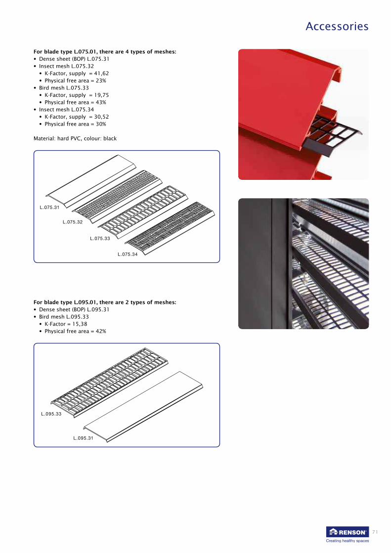
71
L.075.31
L.075.32
L.075.33
L.075.34
L.095.33
L.095.31
Accessories
For blade type L.075.01, there are 4 types of meshes:
• Dense sheet (BOP) L.075.31
• Insect mesh L.075.32
• K-Factor, supply = 41,62
• Physical free area = 23%
• Bird mesh L.075.33
• K-Factor, supply = 19,75
• Physical free area = 43%
• Insect mesh L.075.34
• K-Factor, supply = 30,52
• Physical free area = 30%
Material: hard PVC, colour: black
For blade type L.095.01, there are 2 types of meshes:
• Dense sheet (BOP) L.095.31
• Bird mesh L.095.33
• K-Factor = 15,38
• Physical free area = 42%

72
Ref. LZ.4140
Ref. LZ.4201
95
62.4
2
Accessories
B. Sills
A sill (type LZ.4140) can be fitted in the CL S to drain rain water off.
Fastener for a sill type LZ.4201
Instead of a sill, a frame can be used for the L.075 system (see item C).

73
LZ.4212
L.050W.21
LZ.4213L.050W.21
159
42.5
10
92°
Accessories
C. Aluminium frames
The high performant system L.050W can be provided with an optional
frame profile L.050W.21 which will result in an ideal water drainage.
This frame profile will be installed both horizontally and vertically
around the wall opening and is used in combination with mullion profile
LD.0240. These mullion profiles LD.0240, with pre-assembled clipses
L.050W.11, are to be installed onto structural mullions (type RENSON®
or a structural substructure) and provided with stainless steel mesh. In
this way incoming water is drained back to the outside.
New!

74
L.075.21
L.075.22
L.075.41
LZ.4207
LZ.4208
L.075.21
L.075.41
L.075.03 L.075.03
L.075.41
L.075.22
LD.0460
40
113
44
21.5
8.6
113
44
114
44
40
75
63.5
Accessories
C. Aluminium frames
The louvre system type 75 has been designed with the option of being
provided with a frame with or without flange.
The design with flange gives the aesthetically attractive appearance of a
continuous blade surface.
A sealing rubber can be used to give the louvre a perfect finish so
use of silicone putty is unnecessary.
LZ.4207: Corner trim connectorLZ.4208: Intermediate trim connector

75
C
PIVOT
PIVOT
Accessories
D. Doors
RENSON® offers single or double doors in custom made sizes, opening
inwards or outwards. In some cases, access behind the continuous
louvre system is required, for example to maintain and service (hidden)
industrial appliances.
The doors are fitted with locks, pivots, handles and restraining chain
upon specification.
Difference between overall size (O) and clear door opening (C)
Type blade:L.033 /
L.033.08L.033V L.050 /
L.050HFL.050.021 L.060AC /
L.060HFL.065AL L.066
O - C (mm) single double single double single double single double single double single double single double
Opening outwards 259,5 399 259,5 399 259,5 399 259,5 399 279,5 439 259,5 399 259,5 399
Opening inwards 218 - 237 - 238,5 - 238,5 - 275,5 - 246 - 252,5 -
Type lamel: L.066P L.066V L.066.21 L.075 L.095 L.120 L.150ACS
O - C (mm) single double single double single double single double single double single double single double
Opening outwards 259,5 399 259,5 399 259,5 399 259,5 399 279,5 439 309,5 499 539,5 959
Opening inwards 252,5 - 246 - 252,5 - 261,5 - 275,5 - 288 - 365 -
Please note that the actual opening (C) is smaller than the total door size
(O) due to the pivoting mechanism. The position of the pivot system will
in turn depend on the total load of the louvre door. RENSON® can assist
you in determining the correct sizes.
Clear door opening: C
Overall door size: O
Pivots

76
30
290
20
20
ø5 (2x)
4195
200 200
12.5
12.5
ø3.5 (3x)
Accessories
Handles and locks
One can choose between none, a single or a double door handle. If you
choose not to fit a door handle you can open and close the door with
the key to the lock. The handle can be a fixed door knob or a standard
handle. It is important to specify the handle type.
STANDARD SOLUTION SINGLE HANDLE
The Litto cylinder is the only approved option. Other proposals can be
considered if full technical data is provided to
RENSON®. Other types are available on request.
Accessories such as door dampers, storm chain,... are available on
request.
Door restrictor
A door restrictor is available as an option

77
Specialties
A. Linius® unitized system
Description
Innovative products are always challenging in terms of design, tech-
nique, flexibility and quality! To save valuable time in the assembly
process on site, RENSON® developed the Linius® unitized system.
The advantage of this system is that it allows an entire louvre system to
be divided into modules, which arrive on site in pre-assembled condi-
tion. Upon installation of the mullions on site, successive cassettes can
be easily and quickly installed using a clasping system.
Benefits
• Delivered as pre-assembled cassettes, hence:
- Quick installation, using clasped blades and simple clasping system
- Simple installation and alignment
- Easy assembly in hard-to-reach areas, e.g. high installations,
only accessible from the interior …
• Elements with invisible, encompassing frames
• Removable cassettes, e.g. machine areas
• Reclining elements possible
• Available with enfolded stainless steel mesh
• Elements for mitred corners possible
• Aesthetic appearance, solid and stable system
Properties
• Max. dimensions: 4m² per element – 9 to 16kg/m2
• Cassette layout optional according to grid
• All Linius® range blades are suitable
• Assembly using lever for smaller cassettes
OR using hoisting eye for larger cassettes and for high installations
(crane)
• Technical documentation available
Materials
Aluminium extrusion, alloy EN AW 6063 T66.
Finish
• Anodised F1 (20 micron)
• Polyester powder coating RAL or Syntha Pulvin® colours
(60 - 80 μ/40 μ (UK))
Mesh
Enfolded assembly of stainless steel mesh to the back of the cassettes
hendel
hijsoog

78
Specialties
B. Curved blades
Today’s designs often call for expressive forms giving a building a
specific look.
RENSON® has developed a curved assembly system that allows the archi-
tect’s creativity to be transformed into reality.
Blade types L.033.01, L.033HF, L.050.00 and L.050HF can be delivered
with an minimal outer radius of 800 mm.
In addition, blade types L.033.01 and L.050.00 can also be curved with a
minimal inner radius of 800 mm.
Plans for such a curved design must be submitted to the technical de-
partment at RENSON® for approval before the start of the construction
process.

79
64
69
15
20
91
L.060AC
147
239
69
45
276
L.150ACL.01
328
69
22245
393
L.150ACS.01
2#
3H
H
30°
LD.0995
LZ.4210 + LZ4211
LD.0460
LZ.4203 + 2x LZ.4211
LZ.4210
Specialties
C. Stand alone support structures
This system is used for freestanding louvre systems of limited sizes
and/or wind loads where an additional primary steel structure is ren-
dered unnecessary by a self-supporting aluminium structure.
D. Acoustic applications
Noise nuisance is an environmental pollutant.
We at RENSON® are fully aware of this. As a solution, RENSON® offers an
acoustic louvre that reduces noise pollution and complies with existing
regulations.
This acoustic louvre system allows air passage while reducing noise pas-
sage. The RENSON® technical department is at your disposal to advise
and discuss a suitable acoustic construction.
In order to determine the ideal solution, the following factors are
important:
• the desired dB noise level
• the noise level of the noise source
• the distance and location of the noise
• the required flow rate
The acoustic continuous louvre system consists of a support structure,
acoustic blades and blade supports.
The acoustic blade is filled with sound absorbing and non-combustible
mineral wool.

80
2.
Specialties
E. Mitred corners
Where a corner is formed, the blades are cut to the correct angle so they
fit perfectly and ensure an attractive aesthetic finish.
Possible solutions to fit corners
1.
Expansion
The mullions are fitted as close as possible to the corner
Expansion joint included in mitre
The mullions are fitted as close as possible to the corner
No thermal expansion
between the blades
Thermal
expansion
Fixation
(riveted)
Thermal
expansion Fixation
(riveted)
Thermal
expansion
No fixation

81
133.2
33.3
60.4
150
50
81
Specialties
F. Special shapes
RENSON® long ago moved on from the limits of a simple square design,
and has continuously conceived solutions for spe cific applications.
These are applications mainly intended to create a certain aesthetic
added value, but also applications where functional requirements must
be combined with a contemporary design.
G. Block blades L.033 and L.050
This type of blade offers fast and easy assembly and better vandalism-
resistance than the standard aluminium CL S. The blades can only be
used for riveting or screw-fixing to an existing full back structure (wall,
metal sheeting, …).
The extruded profiles are only available in types L.033 or L.050.
They consist of 3 to 4 blades extruded together. The profiles are
available as punched (L.033.07 / L.050.07) or unpunched (L.033.05 /
L.050.05) versions. The block blades can be used in conjunction with
the standard blades.
Available in lengths to 6000 mm
Available in lengths to 6000 mm

82
Specialties
H. Turrets
A turret is placed on the rooftop of buildings to conceal industrial
appliances. (chimney stacks,....)
RENSON® takes care of complete construction including the top plate
and sill.
I. Louvre grilles
Linius® CLS blades can also be used for assembled made-to-measure
louvres. These louvres are made of frame profiles for building in or
surface mounting, filled with a blade type depending on passage or aes-
thetic requirements, optionally fitted with a stainless steel insect mesh.
The louvres grilles and louvre system can then be aesthetically matched.
Louvre grilles are available in all forms, sizes, RAL colours, and as per-
manent or lockable versions. Louvre grilles with moving blades, sliding
panels, or fixed or removable surface-mounted grilles for windows are
also available.
SYSTEM BLADE BLADE TYPE Pitch GRILLE
L.033 L.033.01 Standard blade 33,3mm 411 ; 414 ; 414D ; 414VA ; 414THF ; 431 ; 432 ; 440/11
L.033.08 L.033.08 Labyrinthe blade 33,3mm 494
L.033V L.033V V-blade 33,3mm 422 ; 428
L.050 L.050.00 Standard blade 50mm 421 ; 424 ; 440/21
L.050HF L.050HF Blade with large free area 50mm 481 ; 484
L.060AC L.060AC Acoustic blade 60mm 445/86 ; 445/86GL
L.060HF L.060HF Blade with large free area 60mm 480 ; 483
L.065AL L.065AL.01 Rolled sheet blade 65mm 453
L.066 L.066.01 Standard blade 66mm 451
L.066V L.066V V-blade 66mm 452 ; 452V
L.095 L.095.01 Standard blade 95mm 425 ; 425/GL
L.150ACL L.150ACL.01 Acoustic blade 150mm 446/225
L.150ACS L.150ACS.01 Acoustic blade 150mm 446/150
L.170ACL L.150ACL.01 Acoustic blade 170mm 447/225
L.170ACS L.150ACS.01 Acoustic blade 170mm 447/150

83
Sunclips®
Icarus®
40
30
0
60
15
0
20
0
20
0
35
8060605042
35
322523
20
0
10
30
3 0 40
48
0
40
0
36
0
30
0
25
0
20
0
15
0
12
5
10
0
32
15
0
Storage and maintenance
J. Aesthetic façade cladding
with Sunclips® and Icarus® blades
Besides the range of louvre systems, RENSON® also offers a whole range
of aluminium profiles suitable for sunshading structures.
One of the systems can be vertically fitted to act as a louvre. This struc-
ture is mainly intended for purely aesthetic applications and/or sun-
shading.
Care of equipment and materials
To avoid deformation of blades etc. it is imperative to use ‘soft
handling’ methods to unload and store materials. Deliveries on pallets
may never be stacked more than two high to minimise exposing others
on the site to risk.
To prevent damage during storage, handling or delivery one must com-
ply with the following rules:
• the products are preferably stored inside.
• with open outside storage, remove the packaging to prevent the entry
of water and any overheating.
• never place the elements directly on damp ground.
• during storage one must guarantee sufficient ventilation of the ele-
ments.
• soiling by cement, mortar or lime must be immediately removed with
plenty of clean water.
Make sure that nearby material or installations cannot accidentally fall
against the boxes and cause damage. The components are packed in
wooden crates to protect them against damage. Packages and boxes
are labelled with the content. The label has a bar code with the internal
computer system reference. Where possible the link is made with the
production drawings that can be sent with the goods.
Deliveries are planned so the correct material arrives in the correct place
in the preferred order of use!
For more info see the Sunclips® and Icarus®
brochures

84
Storage and maintenance
General instructions
1. INSTALLATING DOOR ELEMENTS
• For ease of transport, the leaves for large or double doors may be delivered loose. Fitting and removing door leaves: see
“Instructions for assembly”
• In order to ensure that the blades in the CLS and those on the door are in line and so maintain the linearity of the louvre, it is
recommended to first put the door element in place and only then to locate the support structures next to that element.
• They must be installed perfectly vertically on both sides to be sure the door will work properly. It is also very important for
the batten at the base of the frame (and the pivot, especially) to be fully supported.
• It is fitted using brackets from Renson and anchoring materials specified and supplied by the installer.
2. INSTALLING INSECT, BIRD OR VERMIN MESH (OPTIONAL)
• PVC strips clipped between the blades after blade installation. These strips are available for blades L.050.01, L.075.01 and
L.095.01.
They are clipped in place by the lip of the blade.
• Stainless wire mesh V2A in 2.3 x 2.3 mm, 6 x 6 mm, 10 x 10 mm or 20 x 20 mm mesh (supplied on roll).
The mesh is fixed to the substructure or the support structures.
Suggestion: First attach an angle bracket to the support, then use a plate to bolt the mesh to the bracket.
3. INSTALLATION OF THE CONTINUOUS LOUVRE SYSTEM
3.1 Thermal dilation
When planning and assembling the strip wall system and the dilation joint, the thermal expansion of the aluminium must
always be taken into account. The thermal expansion coefficient of aluminium is 0.024 mm/mK (which is approximately
equivalent to expansion of 1 mm/m with a rise in temperature of 40° C). In the event of major temperature fluctuations,
the possibility of the harmless thermal expansion causing cracking sounds cannot be discounted.
To prevent that from happening as much as possible, it is important for the support profiles to which the strips are being
attached, to be installed well in line and perfectly plumb. We also recommend using shorter strip lengths so that the total
dilation per profile is kept to a minimum. Selecting the power-coated version also reduces that risk of dilation noise.
3.2 Positioning and aligning support structures
• The following points must be taken into account when planning and before ordering a CLS:
- the maximum allowable separation between the support structures is a function of the type of blade and support
structure, and the local wind loading.
- the vertical clearance between two attachment points is a function of the type of support structure, the clearance
between two support structures and the local wind loading.
For more details, see the Renson louvre documentation.
• Align the support structures with prefitted blade supports laterally such that the blade supports are all at the same
height.
Use suitable equipment such as a laser, cord, etc. to achieve this.
If the height of the supports varies, the blades will not be even and the wall will lose its linear appearance.
If the differences are large, the blade will not clip into the blade support.

85
± L (mm)/1000
± L (mm)/1000≤ 0,1 x L
Storage and maintenance
3.3 Installing support structures at expansion joints
When installing aluminium systems, always allow for the thermal expansion of aluminium.
Its coefficient of thermal expansion is 0.024 mm/mK. To avoid blocking the expansion of the strips after assembly, you
can choose from 2 possible methods at the level of the strip joints.
• Option 1: Installing support structures with double blade support for two blades (type L.XXX.12)
• Option 2: Installing two separate support structures with prefitted standard blade supports (type L.XXX.11)
4. Cleaning frequency
Aluminium elements exposed to regular rain and installed in a neutral atmosphere require thorough cleaning once or twice
a year. Aluminium components situated in an urban or industrial environment need to be thoroughly cleaned at least twice
a year. For coastal areas or areas with a strongly polluted atmosphere this frequency should be increased. Components not
exposed to rain must be cleaned more frequently.
Further and more detailed information for installation are available on our website www.renson.eu
This version is recommended
especially for attachment to
less regular substructures (e.g.
wood) or where there are ex-
treme variations in temperature.
Locate the support structures
as close as possible to the outer
end of the blade. The clearance
between the blade support and
the end of the blade should not
exceed 10% of the allowed free
length of the blade.

86
Summary of RENSON® Linius® continuous louvre system
Product description:
RENSON® Linius® CLS consists of sections of extruded ALMgSi0.5 aluminium with a sur face treatment specified by the architect.
The system consists of water-resistant ventilation blades, for simple and invisible assembly by clipping the blades into the blade
supports included in the system
Standards:
• Aluminium alloy: Al Mg Si 0,5 (F25)
- Standard: EN AW-6063
- Annealing: T66
• Strength calculations based on the following standards:
- ENV 1999-1-1: calculation for aluminium structures
- NBN B-03-002-2: wind load - dynamic effects
- EN 1991-1-4: wind load
Surface treatment:
• Anodised in natural colour F1 (20 micron): pre -treated and anodised
• Powder-coated in RAL colours (60 to 80 micron): aluminium profiles are pre -treated to ensure a firm powder coating, and then
powder-coated
System design:
• BLADES:
- Blade type L .................... of extruded aluminium
- Dimensions: Height: ....................
Depth: ....................
Pitch: ....................
- Invisible assembly by clipping the blades into the corresponding blade support L. .....................11 and L. .....................12
(joint clips)
- Drag coefficient: Cfy (determined using wind tunnel tests): .................... (horizontal direction)
Cfz (determined using wind tunnel tests): .................... (vertical direction)
- Visual free area: ....................
- Physical free area: ....................
- K-FACTOR: ....................
• SUPPORT STRUCTURE
- Support profile LD…………. of extruded aluminium:
- Dimensions: Height: ....................
Depth: ....................
- Minimum moment of inertia Iy = .................... mm4 (at 800Pa wind load)
- Blade clips are pre-assembled onto support profile
- Fixing brackets LZ. ....................l
• SPAn:
- Maximum unsupported span of the said system, at qb = 800 Pa wind load:
Blade: ....................
Support profile: ....................
• SySTEM DEPTH:
- Blade and support profile: ....................
• ACCESSORIES:
- Encompassing frame L.075.21 with flange or L.075.22 without flange.
- Enrollable rubber seal L.075.41 for frame profiles L.075.21; L.075.22
- Corner trim connector LZ.4207 and intermediate trim connector LZ.4208 for frame profiles L.075.21 ; L.075.22
- PVC -strips L. ……. .31, L. ……. .32, L. …….. .33 or L. ……. .34 clicked between the blades - assembly from front possible
- Stainless steel 2.3 x 2.3; 6 x 6 or 20 x 20 mm mesh, attached to the back of the support structure
- Sill profile LZ.4140 and bracket LZ.4201
(Please strike out whichever is not applicable)

87
Summary of RENSON® Linius® continuous louvre system References
Ref. Port City, Rotterdam (nL), L.050.01 curved
Ref. S
pre
e D
reie
ck, B
erlin
(DE), L
.050 H
FA
rch. JS
K A
rchite
kte
n (D
iete
r Scheffe
l), O
2 W
orld
Are
na, B
erlin
(DE)
Arch. Weston Williamson, Sweeny Cresent (UK)
Arch. Archikon BV, Amaliahof, Wissekerke (nL)
Mille
nniu
m T
ow
ers
, Budapest (H
U)

VENTILATION
SUNPROTECTION
OUTDOOR
Dealer
© L
20
06
401
11/14
En
gels
RENSON®: your partner in ventilation and sun protection
RENSON®, headquartered in Waregem (Belgium), is a trendsetter in Europe in natural ventilation and sun protection.
• Creating healthy spaces
From 1909, we’ve been developing energy efficient solutions assuring a healthy and comfortable indoor climate.
Our remarkable headquarters - built according to the ‘Healthy Building Concept’ – is a beautiful example portraying our
corporate mission.
• No speed limit on innovation
A multidisciplinary team of more than 50 R&D employees continually optimize our products and develop new and
innovative concepts.
• Strong in communication
Contact with the customer is of the utmost importance. A group of 70 in-the-field employees worldwide and a powerful
international distribution network are ready to advise you on site. EXIT 5 at Waregem gives you the possibility to
experience our products on your own and provides necessary training for installers.
• A reliable partner in business
We can guarantee our customers optimal quality and service thanks to our environmentally friendly and modern
production sites (with automated powder coating line, anodisation line, uPVC injection molding machinery and mold
making shop) covering an area of 95.000 m².
C r e a t i n g h e a l t h y s p a c e s
RENSON® reserves the right to make technical changes to the products shown.
The latest brochures may be downloaded from www.renson.eu
RENSON® Export Department • Tel. +32 (0)56 62 71 04 • [email protected]
N.V. RENSON® Sunprotection-Projects S.A
Maalbeekstraat 6 • IZ 2 Vijverdam • B-8790 Waregem
Tel. +32 (0)56 62 71 07 • Fax +32 (0)56 62 71 47
[email protected] • www.renson.eu
RENSON® Fabrications LTD
Fairfax Units 1-5 • Bircholt Road • Parkwood Industrial Estate • Maidstone • Kent ME15 9SF
Tel. 01622/754123 • Fax 01622/689478
[email protected] • www.renson.eu