Lingenfelter STOV-004 Speed Based Relay Control …Lingenfelter STOV-004 Speed Based Relay Control...
28
Lingenfelter STOV-004 Speed Based Relay Control Module (vehicle speed activated switch) & Speed to Voltage Converter Instructions Lingenfelter Performance Engineering 1557 Winchester Road Decatur, IN 46733 (260) 724-2552 (260) 724-8761 fax www.lingenfelter.com Release date: 5 March 2016 Revision - 1.3 PN: L460340004
Transcript of Lingenfelter STOV-004 Speed Based Relay Control …Lingenfelter STOV-004 Speed Based Relay Control...

Lingenfelter STOV-004 Speed Based Relay Control Module (vehicle speed activated switch) &
Speed to Voltage Converter Instructions
Lingenfelter Performance Engineering1557 Winchester Road
Decatur, IN 46733(260) 724-2552
(260) 724-8761 faxwww.lingenfelter.com
Release date: 5 March 2016Revision - 1.3
PN: L460340004
Page 2
Parts ListLingenfelter STOV-004 VSS Switch & Speed to
Voltage Converter Controller (PN: L460340004)
# Description Part number1 VSS Switch & Speed to Voltage Converter STOV-0042 Hook & loop tape2 Self-tapping screw AV160371 LPE decal L9200100001 Instructions
Tools & Materials Required• Phillips head screwdriver• Wire crimping tool
Optional Items Description Part number
LPE technician’s screwdriver L950050000Sealed 40 amp relay kit L450100000E38/E67 ECM pin MLX-0334680003e-Boost2 boost controller TS-0301-1003EFILive FlashScan V2 EFIFS2-SEFILive V2 FlashScan Tuner GM applications EFIS2-GMHall Effect speed sensor/driveshaft speed sensor
Description:The Lingenfelter STOV-004 is designed to read the Pulse Per Mile (PPM) from a Vehicle Speed Signal (VSS).The STOV-004 is then able to provide switched outputs and an analog output based on the speed signal. The STOV-004 can accept a speed signal from a Hall Effect VSS sensor, a driveshaft VSS sensor, or the Engine Control Module (ECM) or Powertrain Control Module (PCM) on most late model vehicles.
The STOV-004 can be used to:
• Disable the fans above a certain vehicle speed.
• Lock a Torque Converter Clutch (TCC) above a certain vehicle speed.
• Enable a second stage of boost or nitrous above a certain vehicle speed.
• Triggerabuzzerorwarninglightaboveaspecificvehiclespeed(over-speedwarning).
• Activate the door locks above a certain vehicle speed.
• Control virtually any other device that needs to be turned on or off at a certain vehicle speed.
• Disable a two-step once the vehicle is moving.
• Simulate a stage/gear shift output that works with multi-stage boost and nitrous controllers including:
• e-Boost2 boost controller from Turbosmart
• AMS-1000 boost controller from NLR systems
• Boost Leash, gear based, 1-6 from Leash Electronics

Page 3
Specifications• The Lingenfelter Performance Engineering (LPE) STOV-004 Speed to Voltage Converter and MPH Activated
Switch incorporates a precision 32-bit timer to realize microsecond precision over a wide operating frequency and MPH range.
• Designed to work with most late model vehicles that have a 100 to 60,000 pulse per mile (PPM) vehicle speed output signal available or hall effect sensor.
• Offers the following output capabilities
• MPH activated Window Switch
• MPH activated switch (simple on/off control)
• MPH based pulses (simulate gear/stage)
• VSS Pulse Counter
• 0-5 volts analog output proportional to speed. Speed range is 0-250 MPH
• (0 volts = 0 MPH, 5 volts = 250 MPH). Analog output will increase at a rate of 0.02 volts per MPH (linear relationship between speed and voltage).
• The 0-5 volts Analog and Switched outputs work simultaneously.
• Current draw: 0.1 amp plus current draw of device being controlled.
• Outputs are rated for up to 0.75 amps each.
• The STOV-004 should control a relay for higher current level applications.
• Outputs have a self protect feature and will turn OFF in case of direct short or over current condition.
• Includes a built in 2.2 k Ohm pull up resistor enabled by a DIP switch inside the back cover.
• Operating voltage range: 9.0 to 18.0 volts.
• Input signal type: square wave 12 volts.
• Processed Signal from ECM/PCM vehicle speed sensor.
• Square wave output type sensor (i.e. Hall Effect Sensor)
• Valid frequency range of 0.02778 to 2,350 Hz
• Valid pulse range 100 to 60,000 PPM
• Valid MPH ON and MPH OFF range 0 to 399 MPH
• CustommoldedhightemperatureglassfilledNylon6enclosure.
• Fully encapsulated (potted) construction for increased durability.
• One year warranty (from date of purchase).

Page 4
Table 1: Wiring (as labeled on module)Wire Color Label Notes NotesRed +12V Switched Power Connects to a switched +12V source.Orange +12V Output/Normally OFF This wire provides a +12V output (activated by
the vehicle speed settings)Black Ground Connects to a vehicle ground.Blue Analog Output Signal This is the vehicle speed output voltage (analog
voltage output). This is a 0-5 volt DC output.Gray Ground Output/Normally ON This wire connects to the ground side of the
device you plan to activate.Yellow Ground Output/Normally OFF This wire connects to the ground side of the
device you plan to activate.White PPM Input Signal (VSS) This is the vehicle speed pulse input. This
connects to the ECM/PCM Vehicle Speed Sensor (VSS) output signal or sensor signal wire.
Settings on the front face of the STOV-004:• Single sixteen position switch used to set the PPM during programming. Some positions on the sixteen
position switch are not currently used for anything outside of programming (see page 23).
• Two ten position switches for selecting MPH Low.
• MPH Low x10
• MPH Low x1
• Two ten position switches for selecting MPH High.
• MPH High x10
• MPH High x1
Settings inside the rear cover of the STOV-004:• FivetwopositionDIPswitches(Thelocationoftheseswitchesareshowninthefigureonthenextpage).
• DIP switch #1 and #2 are used to control MPH Low VSS switch point adders.
• DIP switch #1 in the ON (up) position adds 100 MPH to MPH Low.
• DIP switch #2 in the ON (up) position adds 200 MPH to MPH Low.
• DIP switch #3 and #4 are used to control MPH High VSS switch point adders.
• DIP switch #3 in the ON (up) position adds 100 MPH to MPH High.
• DIP switch #4 in the ON (up) position adds 200 MPH to MPH High.
• DIP switch #5 toggles the built in pull-up resistor.
• DIP Switch #5 in the ON (up) position enables the pull-up resistor.
• One push-button
• One push button used to program the vehicle PPM signal.
Page 5
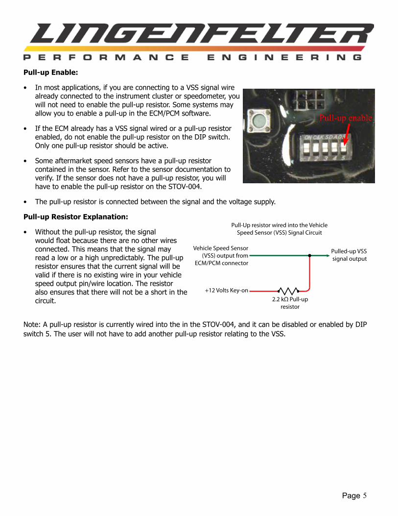
Pull-up Enable:
• In most applications, if you are connecting to a VSS signal wire already connected to the instrument cluster or speedometer, you will not need to enable the pull-up resistor. Some systems may allow you to enable a pull-up in the ECM/PCM software.
• If the ECM already has a VSS signal wired or a pull-up resistor enabled, do not enable the pull-up resistor on the DIP switch. Only one pull-up resistor should be active.
• Some aftermarket speed sensors have a pull-up resistor contained in the sensor. Refer to the sensor documentation to verify. If the sensor does not have a pull-up resistor, you will have to enable the pull-up resistor on the STOV-004.
• The pull-up resistor is connected between the signal and the voltage supply.
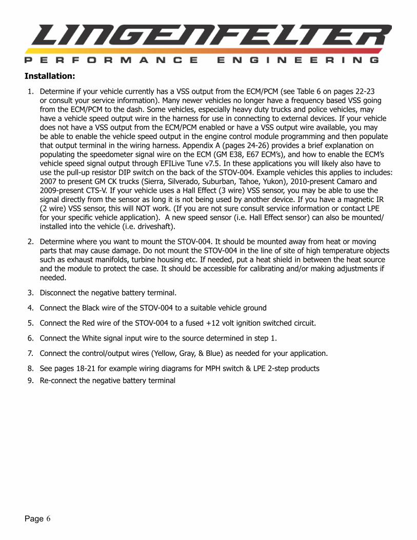
Pull-up Resistor Explanation:
• Without the pull-up resistor, the signal wouldfloatbecausetherearenootherwiresconnected. This means that the signal may read a low or a high unpredictably. The pull-up resistor ensures that the current signal will be valid if there is no existing wire in your vehicle speed output pin/wire location. The resistor also ensures that there will not be a short in the circuit.
Note: A pull-up resistor is currently wired into the in the STOV-004, and it can be disabled or enabled by DIP switch 5. The user will not have to add another pull-up resistor relating to the VSS.
Pull-up enable
Vehicle Speed Sensor (VSS) output from
ECM/PCM connector
+12 Volts Key-on
Pulled-up VSS signal output
2.2 kΩ Pull-up resistor
Pull-Up resistor wired into the Vehicle Speed Sensor (VSS) Signal Circuit
Page 6
Installation:
1. Determine if your vehicle currently has a VSS output from the ECM/PCM (see Table 6 on pages 22-23 or consult your service information). Many newer vehicles no longer have a frequency based VSS going from the ECM/PCM to the dash. Some vehicles, especially heavy duty trucks and police vehicles, may have a vehicle speed output wire in the harness for use in connecting to external devices. If your vehicle does not have a VSS output from the ECM/PCM enabled or have a VSS output wire available, you may be able to enable the vehicle speed output in the engine control module programming and then populate that output terminal in the wiring harness. Appendix A (pages 24-26) provides a brief explanation on populating the speedometer signal wire on the ECM (GM E38, E67 ECM’s), and how to enable the ECM’s vehicle speed signal output through EFILive Tune v7.5. In these applications you will likely also have to use the pull-up resistor DIP switch on the back of the STOV-004. Example vehicles this applies to includes: 2007 to present GM CK trucks (Sierra, Silverado, Suburban, Tahoe, Yukon), 2010-present Camaro and 2009-present CTS-V. If your vehicle uses a Hall Effect (3 wire) VSS sensor, you may be able to use the signal directly from the sensor as long it is not being used by another device. If you have a magnetic IR (2 wire) VSS sensor, this will NOT work. (If you are not sure consult service information or contact LPE foryourspecificvehicleapplication).Anewspeedsensor(i.e.HallEffectsensor)canalsobemounted/installed into the vehicle (i.e. driveshaft).
2. Determine where you want to mount the STOV-004. It should be mounted away from heat or moving parts that may cause damage. Do not mount the STOV-004 in the line of site of high temperature objects such as exhaust manifolds, turbine housing etc. If needed, put a heat shield in between the heat source and the module to protect the case. It should be accessible for calibrating and/or making adjustments if needed.
3. Disconnect the negative battery terminal.
4. Connect the Black wire of the STOV-004 to a suitable vehicle ground
5. Connect the Red wire of the STOV-004 to a fused +12 volt ignition switched circuit.
6. Connect the White signal input wire to the source determined in step 1.
7. Connect the control/output wires (Yellow, Gray, & Blue) as needed for your application.
8. See pages 18-21 for example wiring diagrams for MPH switch & LPE 2-step products
9. Re-connect the negative battery terminal
Page 7
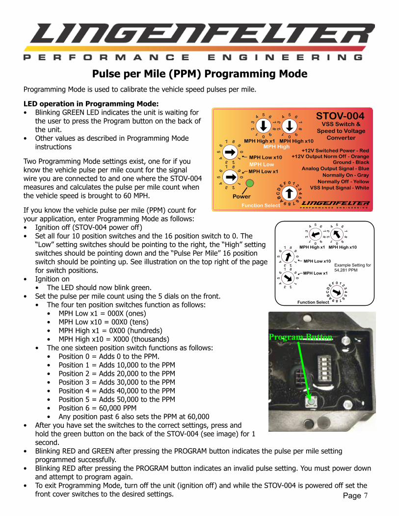
Pulse per Mile (PPM) Programming ModeProgramming Mode is used to calibrate the vehicle speed pulses per mile.
LED operation in Programming Mode:• Blinking GREEN LED indicates the unit is waiting for
the user to press the Program button on the back of the unit.
• Other values as described in Programming Mode instructions
Two Programming Mode settings exist, one for if you know the vehicle pulse per mile count for the signal wire you are connected to and one where the STOV-004 measures and calculates the pulse per mile count when the vehicle speed is brought to 60 MPH.
If you know the vehicle pulse per mile (PPM) count for your application, enter Programming Mode as follows:• Ignition off (STOV-004 power off)• Set all four 10 position switches and the 16 position switch to 0. The
“Low” setting switches should be pointing to the right, the “High” setting switches should be pointing down and the “Pulse Per Mile” 16 position switch should be pointing up. See illustration on the top right of the page for switch positions.
• Ignition on• The LED should now blink green.
• Set the pulse per mile count using the 5 dials on the front.• The four ten position switches function as follows:
• MPH Low x1 = 000X (ones)• MPH Low x10 = 00X0 (tens)• MPH High x1 = 0X00 (hundreds)• MPH High x10 = X000 (thousands)
• The one sixteen position switch functions as follows:• Position 0 = Adds 0 to the PPM.• Position 1 = Adds 10,000 to the PPM• Position 2 = Adds 20,000 to the PPM• Position 3 = Adds 30,000 to the PPM• Position 4 = Adds 40,000 to the PPM• Position 5 = Adds 50,000 to the PPM• Position 6 = 60,000 PPM• Any position past 6 also sets the PPM at 60,000
• After you have set the switches to the correct settings, press and hold the green button on the back of the STOV-004 (see image) for 1 second.
• Blinking RED and GREEN after pressing the PROGRAM button indicates the pulse per mile setting programmed successfully.
• Blinking RED after pressing the PROGRAM button indicates an invalid pulse setting. You must power down and attempt to program again.
• To exit Programming Mode, turn off the unit (ignition off) and while the STOV-004 is powered off set the front cover switches to the desired settings.
Power
STOV-004VSS Switch &
Speed to VoltageConverter
Ground - Black
Normally On - GrayNormally Off - Yellow
MPH Low x10
MPH Low x1
+12V Switched Power - Red
MPH Low
MPH High x10MPH High x1MPH High
Analog Output Signal - Blue
+12V Output Norm Off - Orange
VSS Input Signal - White
Function Select
Example Setting for 54,281 PPM
Function Select
MPH Low x10
MPH Low x1MPH Low
MPH High x10MPH High x1MPH High
Program Button
Page 8
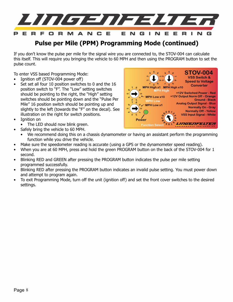
Pulse per Mile (PPM) Programming Mode (continued)
If you don’t know the pulse per mile for the signal wire you are connected to, the STOV-004 can calculate this itself. This will require you bringing the vehicle to 60 MPH and then using the PROGRAM button to set the pulse count.
To enter VSS based Programming Mode:• Ignition off (STOV-004 power off)• Set set all four 10 position switches to 0 and the 16
position switch to “F”. The “Low” setting switches should be pointing to the right, the “High” setting switches should be pointing down and the “Pulse Per Mile” 16 position switch should be pointing up and slightly to the left (towards the “F” on the decal). See illustration on the right for switch positions.
• Ignition on• The LED should now blink green.
• Safely bring the vehicle to 60 MPH.• We recommend doing this on a chassis dynamometer or having an assistant perform the programming
function while you drive the vehicle.• Make sure the speedometer reading is accurate (using a GPS or the dynamometer speed reading).• When you are at 60 MPH, press and hold the green PROGRAM button on the back of the STOV-004 for 1
second.• Blinking RED and GREEN after pressing the PROGRAM button indicates the pulse per mile setting
programmed successfully.• Blinking RED after pressing the PROGRAM button indicates an invalid pulse setting. You must power down
and attempt to program again.• To exit Programming Mode, turn off the unit (ignition off) and set the front cover switches to the desired
settings.
Power
STOV-004VSS Switch &
Speed to VoltageConverter
Ground - Black
Normally On - GrayNormally Off - Yellow
MPH Low x10
MPH Low x1
+12V Switched Power - Red
MPH Low
MPH High x10MPH High x1MPH High
Analog Output Signal - Blue
+12V Output Norm Off - Orange
VSS Input Signal - White
Function Select

Page 9
Speed Based Relay Control Mode
Description:
The STOV-004 can operate as a “Simple Switch” where the outputs switch at a single speed, or it can operate as a “Window Switch” where the outputs switch at one speed and then switch back at another speed (the “Window” being this speed range between the two speed settings).
LED operation in Speed Based Relay Control Mode:• Solid RED when powered up, all settings good and NO VSS signal is present• Solid GREEN when all settings good, VSS signal present and outputs are in the OFF state• Blinking GREEN indicates the outputs are ON• Blinking RED indicates pulse per mile setting is invalid or MPH ON is greater than MPH OFF and MPH
OFF is not equal to 0
Simple Switch Mode, Standard Configuration:
When used as a Simple Switch, the standard mode has a +12V output that is normally off (Norm OFF), a ground output that is normally off (Norm OFF) and a ground output that is normally on (Norm ON). In this mode the outputs function as they are labeled on the product decal.
For standard Simple Switch mode, set both the x1 and the x10 rotary switches for the MPH High setting to 0. Now set the desired switch speed using the MPH Low rotary switches with the x1 switch setting the speed in 1 mph increments and the x10 switch setting the speed in 10 mph increments. The image on the right shows an example of the rotary switches set to 78 MPH.
If you need to set the switch point to above 99 MPH, you will use the DIP switches found behind the back cover of the module. DIP switches 1 and 2 pertain to the MPH Low setting. If switch 1 is on it adds 100 to the MPH Low setting. If switch 2 is on it adds 200 MPH to the MPH Low setting. If 1 and 2 are both on then that adds 300 MPH to the MPH Low setting. The image on the right shows the DIP switch 2 in the on position. This adds 200 MPH to the previous image, and the STOV-004 would switch at 278 MPH.
Example 1:• VehicleSpeedSwitchmode,standardconfiguration(outputsbehaveaslabeledontheproductdecal)• MPH Low = 90 [MPH Low x1 = 0, MPH Low x10 = 9, DIP switch 1 & 2 OFF]• MPH High = 0
Output (Wire Color) Output state below MPH Low Output state above MPH Low+12v activation normally OFF (Orange) OFF (0 volts) ON (+12V)Ground activation normally ON (Gray) ON OFF
Ground activation normally OFF (Yellow) OFF ONSTOV-004 LED status solid GREEN* blinking GREEN
*NOTE: On initial power up the LED will be solid RED unless the PPM setting is invalid and will switch to solid green when a valid speed signal is present.
Standard Simple Switch Mode:Example - 78 MPH
Function Select
MPH Low x10
MPH Low x1MPH Low
MPH High x10MPH High x1MPH High
Page 10
Speed Based Relay Control Mode (continued)
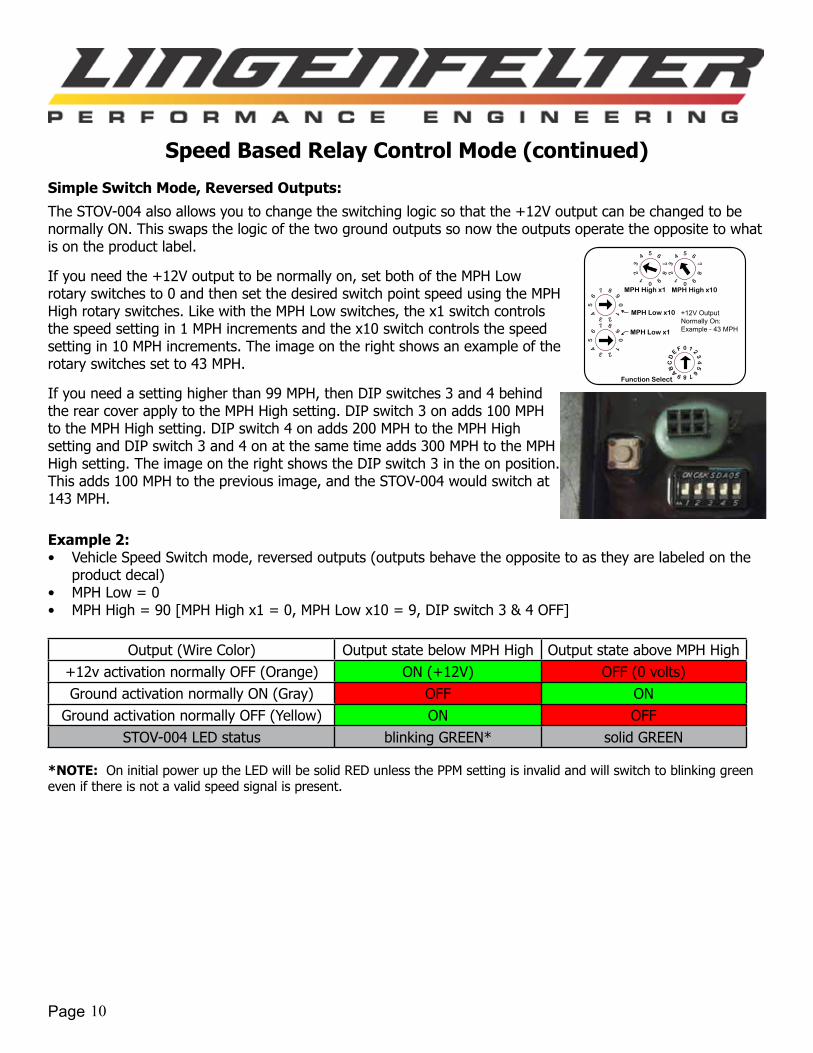
Simple Switch Mode, Reversed Outputs:
The STOV-004 also allows you to change the switching logic so that the +12V output can be changed to be normally ON. This swaps the logic of the two ground outputs so now the outputs operate the opposite to what is on the product label.
If you need the +12V output to be normally on, set both of the MPH Low rotary switches to 0 and then set the desired switch point speed using the MPH High rotary switches. Like with the MPH Low switches, the x1 switch controls the speed setting in 1 MPH increments and the x10 switch controls the speed setting in 10 MPH increments. The image on the right shows an example of the rotary switches set to 43 MPH.
If you need a setting higher than 99 MPH, then DIP switches 3 and 4 behind the rear cover apply to the MPH High setting. DIP switch 3 on adds 100 MPH to the MPH High setting. DIP switch 4 on adds 200 MPH to the MPH High setting and DIP switch 3 and 4 on at the same time adds 300 MPH to the MPH High setting. The image on the right shows the DIP switch 3 in the on position. This adds 100 MPH to the previous image, and the STOV-004 would switch at 143 MPH.
Example 2:• Vehicle Speed Switch mode, reversed outputs (outputs behave the opposite to as they are labeled on the
product decal)• MPH Low = 0• MPH High = 90 [MPH High x1 = 0, MPH Low x10 = 9, DIP switch 3 & 4 OFF]
Output (Wire Color) Output state below MPH High Output state above MPH High+12v activation normally OFF (Orange) ON (+12V) OFF (0 volts)Ground activation normally ON (Gray) OFF ON
Ground activation normally OFF (Yellow) ON OFFSTOV-004 LED status blinking GREEN* solid GREEN
*NOTE: On initial power up the LED will be solid RED unless the PPM setting is invalid and will switch to blinking green even if there is not a valid speed signal is present.
+12V Output Normally On:Example - 43 MPH
Function Select
MPH Low x10
MPH Low x1MPH Low
MPH High x10MPH High x1MPH High
Page 11
Speed Based Relay Control Mode (continued)
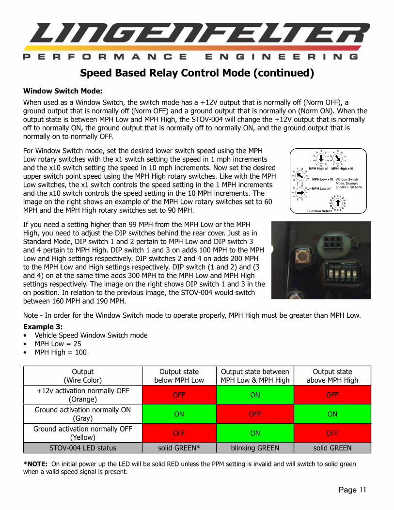
Window Switch Mode:
When used as a Window Switch, the switch mode has a +12V output that is normally off (Norm OFF), a ground output that is normally off (Norm OFF) and a ground output that is normally on (Norm ON). When the output state is between MPH Low and MPH High, the STOV-004 will change the +12V output that is normally off to normally ON, the ground output that is normally off to normally ON, and the ground output that is normally on to normally OFF.
For Window Switch mode, set the desired lower switch speed using the MPH Low rotary switches with the x1 switch setting the speed in 1 mph increments and the x10 switch setting the speed in 10 mph increments. Now set the desired upper switch point speed using the MPH High rotary switches. Like with the MPH Low switches, the x1 switch controls the speed setting in the 1 MPH increments and the x10 switch controls the speed setting in the 10 MPH increments. The image on the right shows an example of the MPH Low rotary switches set to 60 MPH and the MPH High rotary switches set to 90 MPH.
If you need a setting higher than 99 MPH from the MPH Low or the MPH High, you need to adjust the DIP switches behind the rear cover. Just as in Standard Mode, DIP switch 1 and 2 pertain to MPH Low and DIP switch 3 and 4 pertain to MPH High. DIP switch 1 and 3 on adds 100 MPH to the MPH Low and High settings respectively. DIP switches 2 and 4 on adds 200 MPH to the MPH Low and High settings respectively. DIP switch (1 and 2) and (3 and 4) on at the same time adds 300 MPH to the MPH Low and MPH High settings respectively. The image on the right shows DIP switch 1 and 3 in the on position. In relation to the previous image, the STOV-004 would switch between 160 MPH and 190 MPH.
Note - In order for the Window Switch mode to operate properly, MPH High must be greater than MPH Low.
Example 3:• Vehicle Speed Window Switch mode• MPH Low = 25• MPH High = 100
Output(Wire Color)
Output statebelow MPH Low
Output state betweenMPH Low & MPH High
Output stateabove MPH High
+12v activation normally OFF(Orange) OFF ON OFF
Ground activation normally ON(Gray) ON OFF ON
Ground activation normally OFF (Yellow) OFF ON OFF
STOV-004 LED status solid GREEN* blinking GREEN solid GREEN
*NOTE: On initial power up the LED will be solid RED unless the PPM setting is invalid and will switch to solid green when a valid speed signal is present.
Window Switch Mode: Example 60 MPH - 90 MPH
Function Select
MPH Low x10
MPH Low x1MPH Low
MPH High x10MPH High x1MPH High

Page 12
Stage/Gear Shift Output Mode
This mode is used to provide stage/gear shift output for boost controllers and other devices that need to see a gear shift position switch output to change stages such as:
• e-Boost2 boost controller from Turbosmart• AMS-1000 boost controller from NLR systems• Boost Leash, gear based, 1-6 from Leash Electronics
Table 2: Wiring for stage/gear shift output mode (as labeled on module)Wire Color Label NotesRed +12V Switched Power Connects to a switched +12 volt source.Orange +12V Output/Normally OFF Activation - This wire provides a switched +12V output
(activated by the vehicle speed settings).Black Ground Connects to a vehicle ground.Blue Analog Output Signal This is the vehicle speed output voltage (analog voltage
output). This is a 0-5 volt DC output.Gray Ground Output/Normally ON Increasing MPH pulse - This wire provides a pulsed ground
output (activated by the vehicle speed settings).Yellow Ground Output/Normally OFF Reset/Decreasing MPH pulse - This provides a pulsed ground
output (activated by the vehicle speed settings). White PPM Input Signal (VSS) This is the vehicle speed pulse input. This connects to the
ECM/PCM Vehicle Speed Sensor (VSS) output signal or sensor signal wire.
NOTE: In this mode, the four ten position dials are not used for anything outside of programming.
Page 13
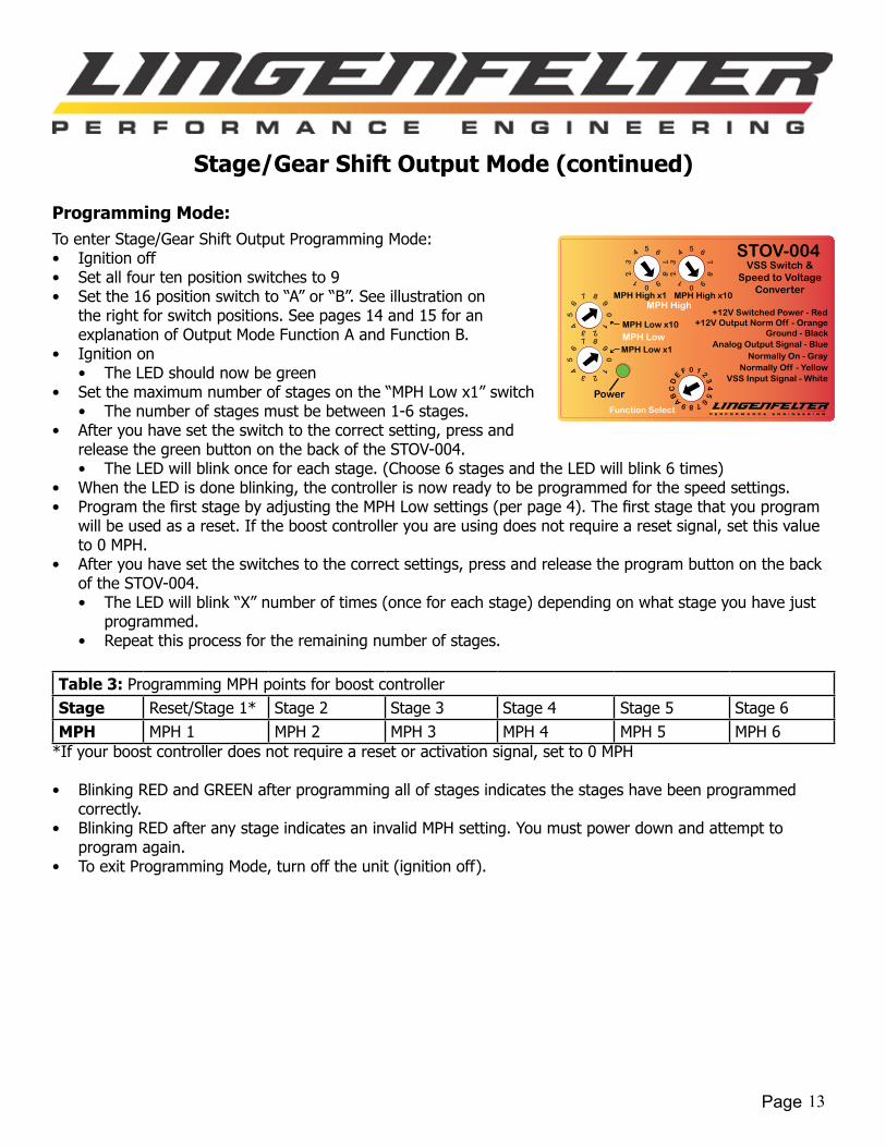
Stage/Gear Shift Output Mode (continued)
Programming Mode:To enter Stage/Gear Shift Output Programming Mode:• Ignition off• Set all four ten position switches to 9• Set the 16 position switch to “A” or “B”. See illustration on
the right for switch positions. See pages 14 and 15 for an explanation of Output Mode Function A and Function B.
• Ignition on• The LED should now be green
• Set the maximum number of stages on the “MPH Low x1” switch• The number of stages must be between 1-6 stages.
• After you have set the switch to the correct setting, press and release the green button on the back of the STOV-004. • The LED will blink once for each stage. (Choose 6 stages and the LED will blink 6 times)
• When the LED is done blinking, the controller is now ready to be programmed for the speed settings.• ProgramthefirststagebyadjustingtheMPHLowsettings(perpage4).Thefirststagethatyouprogram
will be used as a reset. If the boost controller you are using does not require a reset signal, set this value to 0 MPH.
• After you have set the switches to the correct settings, press and release the program button on the back of the STOV-004.• The LED will blink “X” number of times (once for each stage) depending on what stage you have just
programmed.• Repeat this process for the remaining number of stages.
Table 3: Programming MPH points for boost controllerStage Reset/Stage 1* Stage 2 Stage 3 Stage 4 Stage 5 Stage 6MPH MPH 1 MPH 2 MPH 3 MPH 4 MPH 5 MPH 6
*If your boost controller does not require a reset or activation signal, set to 0 MPH
• Blinking RED and GREEN after programming all of stages indicates the stages have been programmed correctly.
• Blinking RED after any stage indicates an invalid MPH setting. You must power down and attempt to program again.
• To exit Programming Mode, turn off the unit (ignition off).
Power
STOV-004VSS Switch &
Speed to VoltageConverter
Ground - Black
Normally On - GrayNormally Off - Yellow
+12V Switched Power - Red
Analog Output Signal - Blue
+12V Output Norm Off - Orange
VSS Input Signal - White
Function Select
MPH Low x10
MPH Low x1MPH Low
MPH High x10MPH High x1MPH High

Page 14
Stage/Gear Shift Output Mode (continued)
Stage/Gear Shift Output Mode Function A:
This function allows you to sequentially switch between different boost settings depending on what the speed of your vehicle is. This mode is compatible with the e-Boost2 boost controller (SSA in e-Boost2 instructions), AMS-1000 boost controller, and Boost Leash, gear based, boost controller.
The ORANGE and YELLOW wires are both used as RESET/ACTIVATION wires. Choose the correct wire depending on your device. If you are using the AMS-1000 boost controller, use the ORANGE wire. If you are using the e-Boost2 boost controller, use the YELLOW wire.
Operation as MPH increases - When the Reset/Stage 1 MPH value is reached, the yellow wire “Normally Off” output will turn ON (output a ground signal) for 0.25 seconds then turn OFF. This provides a pulse to reset the boost controller.
When the Reset/Stage 1 MPH value is reached, the orange wire “+12V Output Norm Off” output will turn OFF (output a ground signal), starting stage 1 boost control. This output will remain OFF until the MPH value drops below the Reset/Stage 1 MPH value.
As MPH increases and becomes greater than or equal to the next stage MPH the gray wire “Normally On” output will turn ON (output a ground signal) for 0.25 seconds then turn OFF, this provides a pulse to increment the boost controller to the next stage. This process continues as MPH increases until the last stage is reached.
As MPH decreases and falls below the Reset/Stage 1 MPH, the yellow wire “Normally Off” output will turn ON (output a ground signal) for 0.25 seconds then turn OFF. This provides a pulse to reset the boost controller.
As MPH decreases and falls below the the Reset/Stage 1 MPH, the orange wire “+12V Output Norm Off” output will turn ON (output a +12V signal), resetting the sequence (and in most systems, resetting your nitrous or boost controller). If MPH increases the above sequence is performed again.
LED operation:
TheLEDwillbereduntilyoureachtheMPHvalueofastage.Oncethevalueisreached,theLEDwillflashgreen.
Example:
For this example, MPH values were arbitrarily chosen. The MPH values are shown in the table below.
As the speed of your vehicle increases the STOV-004 will send a pulse to your boost controller telling your boost controller to go to the next stage. A pulse will only be sent to the boost controller as the speed of your vehicle increases or if you drop below your Reset MPH value. For example, if the speed of your vehicle is 55 MPH and you increase the speed of your vehicle to 75 MPH, the STOV-004 will output a pulse to your boost controller indicating that you have reached your Stage 5 MPH value. Then you continue to increase the speed of your vehicle to 80 MPH. Suddenly, you have to decelerate to 70 MPH. In Output Mode Function A, the STOV-004 will not send a pulse to the boost controller indicating that you dropped below your MPH set point. You will continue operating at Stage 5 boost control. Your boost controller will not reset until you drop below 5 MPH (Reset/Stage 1 speed).
Table 4: Example programmed MPH values for each stage.Stage Reset/Stage 1 Stage 2 Stage 3 Stage 4 Stage 5 Stage 6MPH 5 15 30 50 75 100
If you would like the STOV-004 to send a pulse to your boost controller indicating that the speed of the vehicle fell below your MPH set point, see Output Mode Function B on the next page.

Page 15
Stage/Gear Shift Output Mode (continued)
Stage/Gear Shift Output Mode Function B:
This function allows you to switch up and down between different boost settings depending on what the speed of your vehicle is. This mode is compatible with the e-Boost2 boost controller (SSb in e-Boost2 instructions).
Note: The Reset/Stage 1 MPH value is not used in this function.
Operation as MPH increases - When the next stage MPH value is reached, the gray wire “Normally On” output will turn ON (output a ground signal) for 0.25 seconds then turn OFF, starting the next stage boost control. This provides a pulse to increment the boost controller to the next stage.
Operation as MPH decreases - When the previous stage MPH value is reached, the yellow wire “Normally Off” output will turn ON (output a ground signal) for 0.25 seconds then turn OFF, starting the previous stage boost control this provides a pulse to decrement the boost controller to the previous stage.
LED operation:
• Vehicle MPH increasing - Red LED
• Nextstage-GreenLEDflash
• Vehicle MPH decreasing - Green LED
• PreviousStage-RedLEDflash
Example:For this example, MPH values will be the same as the example in Function A. The values are shown below. The MPH values are shown in the table below.
As the speed of your vehicle increases, the STOV-004 will send a pulse to your boost controller telling your boost controller to go to the next stage. As the speed of your vehicle decreases, the STOV-004 will send a pulse to your boost controller telling your boost controller to go to the previous stage. For example, if the speed of your vehicle is 55 MPH and you increase the speed of your vehicle to 75 MPH, the STOV-004 will output a pulse to your boost controller indicating that you have reached your Stage 5 MPH value. Then you continue to increase the speed of your vehicle to 80 MPH. Suddenly, you have to decelerate to 70 MPH. In Output Mode Function B, the STOV-004 will send a pulse to the boost controller indicating that you dropped below your MPH set point. Depending on your boost controller, you will now be operating at Stage 4 boost control.
Table 5: Example programmed MPH values for each stage.Stage Reset/Stage 1 Stage 2 Stage 3 Stage 4 Stage 5 Stage 6MPH 5 15 30 50 75 100

Page 16
VSS Pulse Counter Mode
This mode is used to activate the relay outputs based on the number of pulses received (from stopped condition) from the Vehicle Speed Sensor (VSS). In VSS Pulse Counter mode, you can select the number of pulses from the VSS that must occur before the outputs on the STOV-004 are activated. You can also select the maximum amount of time the STOV-004 reads 0 MPH before the outputs on the STOV-004 are reset.
Given that you know your vehicle’s PPM and the vehicle maintains traction, you can calculate the approximate distance traveled before the outputs are turned on.
Specifications:• Number of Pulses
• 0-399 pulses• Minimum Time between Pulses
• 0.0011 seconds• Time-Out Condition
• 0.1 - 9.9 seconds.
Settings on the front face of the STOV-004:In the VSS Pulse Counter Mode, the MPH switches on the front face of the STOV-004 no longer control MPH settings. The changes are as follows:
• Single sixteen position switch must be set to “E”
• Two ten position switches for selecting the number of pulses that must occur before the outputs are activated.
• MPH Low x10 = Number of Pulses x10
• MPH Low x1 = Number of Pulses x1
• Two ten position switches for selecting the Time-out condition.
• MPH High x10 = Time (seconds) x1.0
• MPH High x1 = Time (seconds) x0.1
Settings inside the rear cover of the STOV-004:In the VSS Pulse Counter Mode, the MPH switches inside the rear cover of the STOV-004 no longer control MPH settings. The changes are as follows:
• FivetwopositionDIPswitches(Thelocationoftheseswitchesareshowninthefigurebelow).
• DIP switch #1 and #2 are used to control the Number of Pulses switch point adders.
• DIP switch #1 in the ON (up) position adds 100 Pulses.
• DIP switch #2 in the ON (up) position adds 200 Pulses.
• DIP switch #3 and #4 do not function in VSS Pulse Counter Mode.
• DIP switch #5 toggles the built in pull-up resistor.
• DIP Switch #5 in the ON (up) position enables the pull-up resistor.
5280 * (Number of Pulses)PPM
Distance (feet) =PPM * (Distance (feet))
5280or Number of Pulses =

Page 17
VSS Pulse Counter Mode (continued)
LED operation in VSS Pulse Counter Mode:• Solid RED when powered up, all settings good and outputs are in the OFF state• Solid GREEN indicates a valid vehicle speed signal and outputs are in the OFF state• Blinking GREEN indicates the outputs are ON• Blinking RED indicates pulse per mile setting is invalid
If the time-out condition is set to 0 seconds, the outputs will not turn off once activated until the device is powered off.
If the STOV-004 reads 0 MPH for the duration of the Time-Out condition, the outputs will turn off.
Example 1:• VSS Pulse Counter Mode• Time-Out Condition = 0.0 seconds• Known PPM = 4000• Number of Pulses = 27
The outputs will turn on after 27 pulses (approximately 35 feet). The outputs will not turn off until the device is powered off.
Example 2:• VSS Pulse Counter Mode• Time-Out Condition = 2.0 seconds• Known PPM = 8000• Number of Pulses = 100
The outputs will turn on after 100 pulses (approximately 66 feet). The outputs will turn off after the STOV-004 reads 0 MPH for 2.0 seconds or until the device is powered off.
Output(Wire Color)
Output statebelow Number of Pulses or
Time-Out Condition is reached
Output stateabove Number of Pulses
+12v activation normally OFF (Orange) OFF ON
Ground activation normally ON (Gray) ON OFF
Ground activation normally OFF (Yellow) OFF ON
STOV-004 LED status solid RED or solid GREEN blinking GREEN

Page 18
85
86
30
87a 87
+12 Volt Key-On Power
Gro
und
0-5
Volt
outp
ut b
ased
on
MPH
, .02
Vol
ts p
er M
PH
Normally ON Output, ON when MPH is below set point. OFF when MPH exceeds set point.
Normally OFF Output, OFF when MPH is below set point. On when
MPH exceeds set point.
Connect to VSS (Pulse Per Mile) signal from PCM
Relay will ONLY be ON when MPH is below
set point.
Controlled Device Input
Signal Disable Installation(Example- Fan Relay Control)
Controlled Device Output
+12 Volt
01
3
56
7
2
4
8 9A
BCD
EF
01
356
7
2
4
89
AB C D
EF
Power
STOV-003Speed to Voltage
Ground - Black
Stage Out / Norm On - Gray
Activation Out / Norm Off - Green
PPM Signal Input - White
Convertor
Function Selection
Range Selection
+12V Switched Power - Red
Voltage Out - Yellow
Power
STOV-004VSS Switch &
Speed to VoltageConverter
Ground - Black
Normally On - GrayNormally Off - Yellow
MPH Low x10
MPH Low x1
+12V Switched Power - Red
MPH Low
MPH High x10MPH High x1MPH High
Analog Output Signal - Blue
+12V Output Norm Off - Orange
VSS Input Signal - White
Function Select

Page 19
In this con�guration, the STOV-004 is being used to only allow a 2-step controller to be active at the line. Once the vehicle is moving, the STOV-004 switches the relay, disabling the 2-step controller. Set the MPH switch point to a speed below your �rst gear shift point.
1 - Locate the CPP (Clutch Pedal Position) Switch and unplug the 2-wire connector.2 - Cut wires appox. 3" back from connector.3 - Find +12 volt Key On power source and connect to one wire of the CPP connector.4 - Splice two wires onto the remaining CPP connector wire and connect one wire to #85 on the Relay. The extra wire will be used for LNC-2000 Launch Controller activation.5 - Connect terminal #86 on the Relay to Ground.6 - Connect wires cut from CPP Switch connector to Terminals #30 and #87 as shown.7 - Set the STOV-004 MPH switch point to a speed just below your �rst shift point.
1998-2002 F-Body and 1997-2007 Corvette Factory Clutch Switch Diagram with the STOV-004 and LNC-2000 Modules
Wire color illustrated isfor 1999 TransAm
85
86
30
87a 87
2
4
Ground
5
General purposeAutomotive Relay.5 to 40 Amp
6
3
01
3
56
7
2
4
8 9A
BCD
EF
01
356
7
2
4
89
AB C D E
F
Power
STOV-002Speed to Voltage
Ground - Black
Stage Out / Norm On - Gray
Activation Out / Norm Off - Green
PPM Signal Input - White
Convertor
Function Selection
Range Selection
+12V Switched Power - Red
Voltage Out - Yellow
Power
STOV-004VSS Switch &
Speed to VoltageConverter
Ground - Black
Normally On - GrayNormally Off - Yellow
MPH Low x10
MPH Low x1
+12V Switched Power - Red
MPH Low
MPH High x10MPH High x1MPH High
Analog Output Signal - Blue
+12V Output Norm Off - Orange
VSS Input Signal - White
Function Select
LNC-2000
Red = MAP +5VBlack = MAP/Linear GroundPurple = MAP/Linear Signal
F = Linear Mode .2 Volt = 0* 4.8 Volt = 15*
Max Retard
85
86
30
87a 87
+12 Volt Key-On Power
Grou
nd
0-5
Volt
outp
ut b
ased
on
MPH
, .02
Volts
per
MPH
LNC-2000 or LNC-003 +12V Activation
Normally ON Output, ON when MPH is below set point. OFF when MPH
exceeds set point.
Normally OFF Output, OFF when MPH is below set point. On when
MPH exceeds set point.
Connect to Pulse Per Mile signal from PCM
+12 Volt Key-On Power
Relay will ONLY be ON when MPH is below
set point.
1
Page 20
LNC-2014
Red = MAP +5VBlack = MAP/Linear GroundPurple = MAP/Linear Signal
F = Linear Mode .2 Volt = 0* 4.8 Volt = 15*
Max Retard
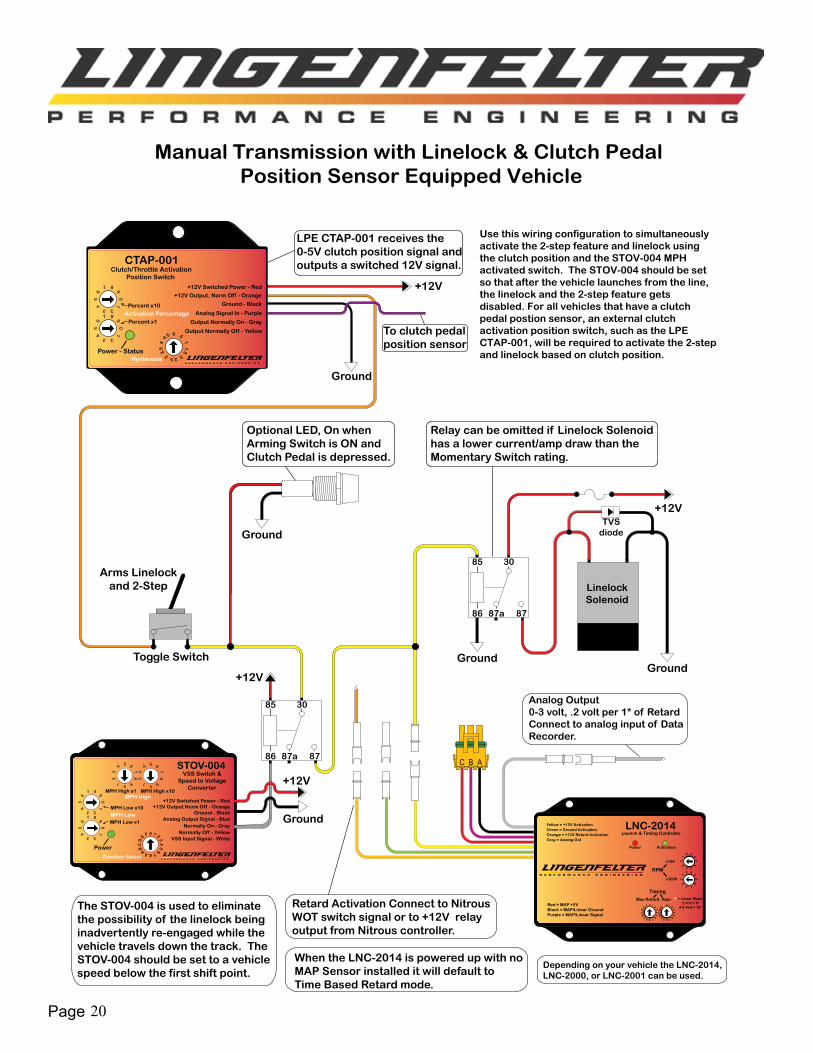
Manual Transmission with Linelock & Clutch Pedal Position Sensor Equipped Vehicle
ABC
Toggle Switch
Arms Linelockand 2-Step
Ground
85
86
30
87a 87
Ground
LinelockSolenoid
+12V
Ground
Optional LED, On whenArming Switch is ON andClutch Pedal is depressed.
Relay can be omitted if Linelock Solenoidhas a lower current/amp draw than theMomentary Switch rating.
Analog Output0-3 volt, .2 volt per 1* of RetardConnect to analog input of DataRecorder.
Retard Activation Connect to NitrousWOT switch signal or to +12V relayoutput from Nitrous controller.
Use this wiring configuration to simultaneously activate the 2-step feature and linelock using the clutch position and the STOV-004 MPH activated switch. The STOV-004 should be set so that after the vehicle launches from the line, the linelock and the 2-step feature gets disabled. For all vehicles that have a clutch pedal postion sensor, an external clutch activation position switch, such as the LPE CTAP-001, will be required to activate the 2-step and linelock based on clutch position.
+12V
Ground
Power - Status
CTAP-001Clutch/Throttle Activation
Ground - Black
Output Normally On - Gray
Output Normally Off - Yellow
Position Switch
Percent x10
Percent x1
+12V Switched Power - Red
Activation Percentage Analog Signal In - Purple
+12V Output, Norm Off - Orange
Hysteresis
0 .5
11.5
22.53
3.5
4
4.5
LPE CTAP-001 receives the 0-5V clutch position signal and outputs a switched 12V signal.
To clutch pedal position sensor
TVS diode
When the LNC-2014 is powered up with noMAP Sensor installed it will default toTime Based Retard mode.
85
86
30
87a 87
Ground
+12V
+12V
The STOV-004 is used to eliminatethe possibility of the linelock being inadvertently re-engaged while thevehicle travels down the track. TheSTOV-004 should be set to a vehiclespeed below the first shift point.
Power
STOV-004VSS Switch &
Speed to VoltageConverter
Ground - Black
Normally On - GrayNormally Off - Yellow
MPH Low x10
MPH Low x1
+12V Switched Power - Red
MPH Low
MPH High x10MPH High x1MPH High
Analog Output Signal - Blue
+12V Output Norm Off - Orange
VSS Input Signal - White
Function Select
Depending on your vehicle the LNC-2014, LNC-2000, or LNC-2001 can be used.
Page 21
LNC-2014
Red = MAP +5VBlack = MAP/Linear GroundPurple = MAP/Linear Signal
F = Linear Mode .2 Volt = 0* 4.8 Volt = 15*
Max Retard
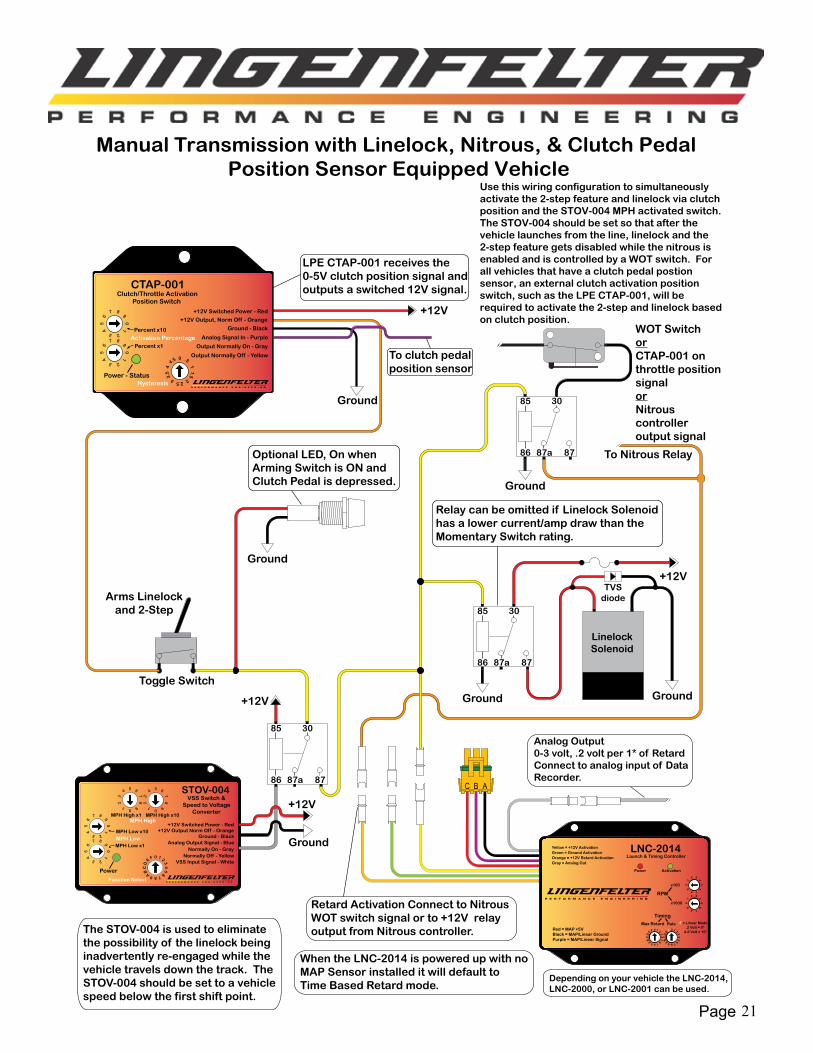
Manual Transmission with Linelock, Nitrous, & Clutch Pedal Position Sensor Equipped Vehicle
ABC
Toggle Switch
Arms Linelockand 2-Step
Ground
85
86
30
87a 87
Ground
LinelockSolenoid
+12V
Ground
Optional LED, On whenArming Switch is ON andClutch Pedal is depressed.
Relay can be omitted if Linelock Solenoidhas a lower current/amp draw than theMomentary Switch rating.
Analog Output0-3 volt, .2 volt per 1* of RetardConnect to analog input of DataRecorder.
Retard Activation Connect to NitrousWOT switch signal or to +12V relayoutput from Nitrous controller.
85
86
30
87a 87
Ground
To Nitrous Relay
Use this wiring configuration to simultaneously activate the 2-step feature and linelock via clutch position and the STOV-004 MPH activated switch. The STOV-004 should be set so that after the vehicle launches from the line, linelock and the 2-step feature gets disabled while the nitrous is enabled and is controlled by a WOT switch. For all vehicles that have a clutch pedal postion sensor, an external clutch activation position switch, such as the LPE CTAP-001, will be required to activate the 2-step and linelock based on clutch position.
+12V
Ground
Power - Status
CTAP-001Clutch/Throttle Activation
Ground - Black
Output Normally On - Gray
Output Normally Off - Yellow
Position Switch
Percent x10
Percent x1
+12V Switched Power - Red
Activation Percentage Analog Signal In - Purple
+12V Output, Norm Off - Orange
Hysteresis
0 .5
11.5
22.53
3.5
4
4.5
LPE CTAP-001 receives the 0-5V clutch position signal and outputs a switched 12V signal.
To clutch pedal position sensor
TVS diode
WOT SwitchorCTAP-001 on throttle position signalorNitrous controlleroutput signal
Power
STOV-004VSS Switch &
Speed to VoltageConverter
Ground - Black
Normally On - GrayNormally Off - Yellow
MPH Low x10
MPH Low x1
+12V Switched Power - Red
MPH Low
MPH High x10MPH High x1MPH High
Analog Output Signal - Blue
+12V Output Norm Off - Orange
VSS Input Signal - White
Function Select
85
86
30
87a 87
Ground
+12V
+12V
The STOV-004 is used to eliminatethe possibility of the linelock being inadvertently re-engaged while thevehicle travels down the track. TheSTOV-004 should be set to a vehiclespeed below the first shift point.
When the LNC-2014 is powered up with noMAP Sensor installed it will default toTime Based Retard mode.
Depending on your vehicle the LNC-2014, LNC-2000, or LNC-2001 can be used.
Page 22
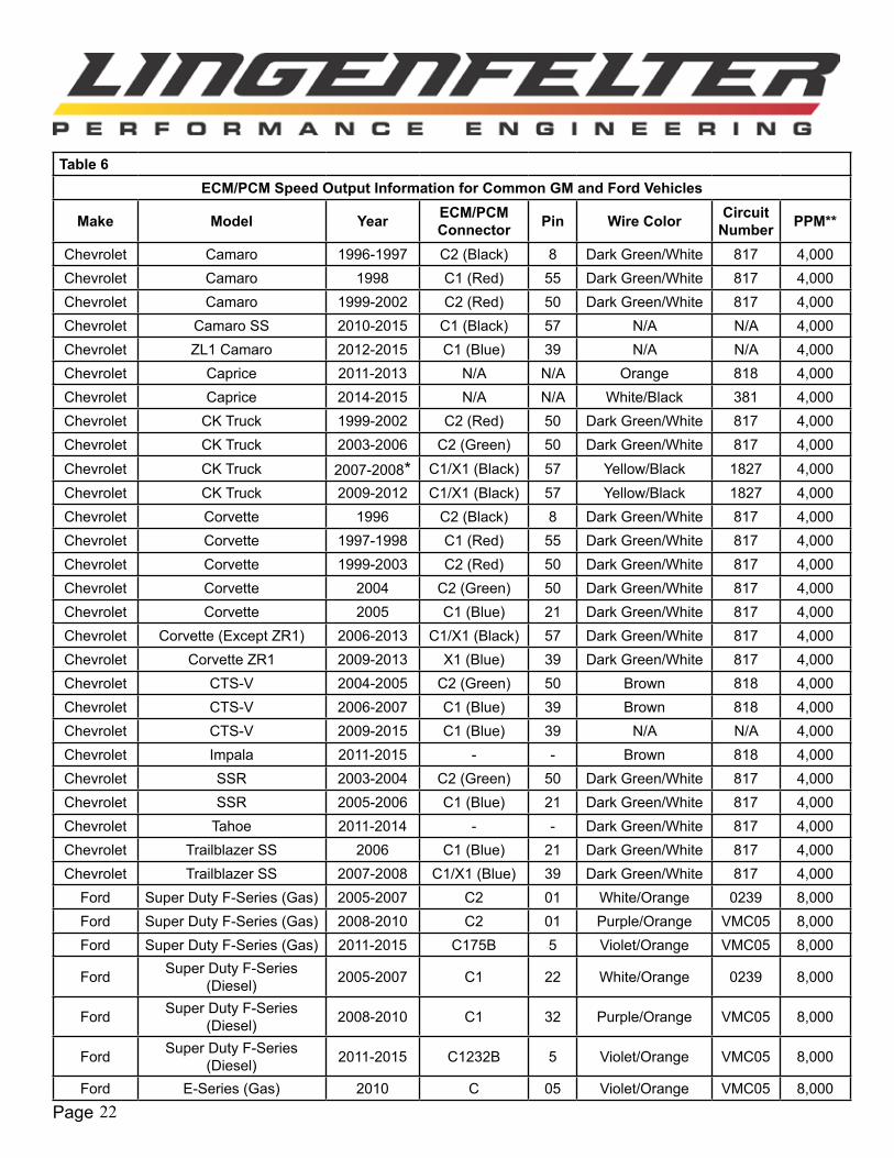
Table 6ECM/PCM Speed Output Information for Common GM and Ford Vehicles
Make Model Year ECM/PCM Connector Pin Wire Color Circuit
Number PPM**
Chevrolet Camaro 1996-1997 C2 (Black) 8 Dark Green/White 817 4,000Chevrolet Camaro 1998 C1 (Red) 55 Dark Green/White 817 4,000Chevrolet Camaro 1999-2002 C2 (Red) 50 Dark Green/White 817 4,000Chevrolet Camaro SS 2010-2015 C1 (Black) 57 N/A N/A 4,000Chevrolet ZL1 Camaro 2012-2015 C1 (Blue) 39 N/A N/A 4,000Chevrolet Caprice 2011-2013 N/A N/A Orange 818 4,000Chevrolet Caprice 2014-2015 N/A N/A White/Black 381 4,000Chevrolet CK Truck 1999-2002 C2 (Red) 50 Dark Green/White 817 4,000Chevrolet CK Truck 2003-2006 C2 (Green) 50 Dark Green/White 817 4,000Chevrolet CK Truck 2007-2008* C1/X1 (Black) 57 Yellow/Black 1827 4,000Chevrolet CK Truck 2009-2012 C1/X1 (Black) 57 Yellow/Black 1827 4,000Chevrolet Corvette 1996 C2 (Black) 8 Dark Green/White 817 4,000Chevrolet Corvette 1997-1998 C1 (Red) 55 Dark Green/White 817 4,000Chevrolet Corvette 1999-2003 C2 (Red) 50 Dark Green/White 817 4,000Chevrolet Corvette 2004 C2 (Green) 50 Dark Green/White 817 4,000Chevrolet Corvette 2005 C1 (Blue) 21 Dark Green/White 817 4,000Chevrolet Corvette (Except ZR1) 2006-2013 C1/X1 (Black) 57 Dark Green/White 817 4,000Chevrolet Corvette ZR1 2009-2013 X1 (Blue) 39 Dark Green/White 817 4,000Chevrolet CTS-V 2004-2005 C2 (Green) 50 Brown 818 4,000Chevrolet CTS-V 2006-2007 C1 (Blue) 39 Brown 818 4,000Chevrolet CTS-V 2009-2015 C1 (Blue) 39 N/A N/A 4,000Chevrolet Impala 2011-2015 - - Brown 818 4,000Chevrolet SSR 2003-2004 C2 (Green) 50 Dark Green/White 817 4,000Chevrolet SSR 2005-2006 C1 (Blue) 21 Dark Green/White 817 4,000Chevrolet Tahoe 2011-2014 - - Dark Green/White 817 4,000Chevrolet Trailblazer SS 2006 C1 (Blue) 21 Dark Green/White 817 4,000Chevrolet Trailblazer SS 2007-2008 C1/X1 (Blue) 39 Dark Green/White 817 4,000
Ford Super Duty F-Series (Gas) 2005-2007 C2 01 White/Orange 0239 8,000Ford Super Duty F-Series (Gas) 2008-2010 C2 01 Purple/Orange VMC05 8,000Ford Super Duty F-Series (Gas) 2011-2015 C175B 5 Violet/Orange VMC05 8,000
Ford Super Duty F-Series (Diesel) 2005-2007 C1 22 White/Orange 0239 8,000
Ford Super Duty F-Series (Diesel) 2008-2010 C1 32 Purple/Orange VMC05 8,000
Ford Super Duty F-Series (Diesel) 2011-2015 C1232B 5 Violet/Orange VMC05 8,000
Ford E-Series (Gas) 2010 C 05 Violet/Orange VMC05 8,000
Page 23
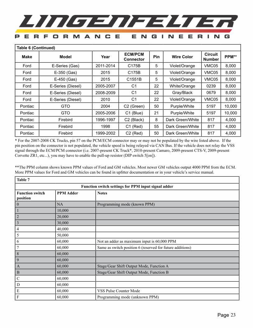
Table 6 (Continued)
Make Model Year ECM/PCM Connector Pin Wire Color Circuit
Number PPM**
Ford E-Series (Gas) 2011-2014 C175B 5 Violet/Orange VMC05 8,000Ford E-350 (Gas) 2015 C175B 5 Violet/Orange VMC05 8,000Ford E-450 (Gas) 2015 C1551B 5 Violet/Orange VMC05 8,000Ford E-Series (Diesel) 2005-2007 C1 22 White/Orange 0239 8,000Ford E-Series (Diesel) 2008-2009 C1 22 Gray/Black 0679 8,000
Ford E-Series (Diesel) 2010 C1 22 Violet/Orange VMC05 8,000
Pontiac GTO 2004 C2 (Green) 50 Purple/White 5197 10,000Pontiac GTO 2005-2006 C1 (Blue) 21 Purple/White 5197 10,000Pontiac Firebird 1996-1997 C2 (Black) 8 Dark Green/White 817 4,000Pontiac Firebird 1998 C1 (Red) 55 Dark Green/White 817 4,000Pontiac Firebird 1999-2002 C2 (Red) 50 Dark Green/White 817 4,000
* For the 2007-2008 CK Trucks, pin 57 on the PCM/ECM connector may or may not be populated by the wire listed above. If the pin position on the connector is not populated, the vehicle speed is being relayed via CAN Bus. If the vehicle does not relay the VSS signal through the ECM/PCM connector (i.e. 2007-present CK Truck*, 2010-present Camaro, 2009-present CTS-V, 2009-present Corvette ZR1, etc...), you may have to enable the pull-up resistor (DIP switch 5[on]).
**The PPM column shows known PPM values of Ford and GM vehicles. Most newer GM vehicles output 4000 PPM from the ECM. More PPM values for Ford and GM vehicles can be found in upfitter documentation or in your vehicle’s service manual.
Table 7Function switch settings for PPM input signal adder
Function switch position
PPM Adder Notes
0 NA Programming mode (known PPM)1 10,0002 20,0003 30,0004 40,0005 50,0006 60,000 Not an adder as maximum input is 60,000 PPM7 60,000 Same as switch position 6 (reserved for future additions)8 60,0009 60,000A 60,000 Stage/Gear Shift Output Mode, Function AB 60,000 Stage/Gear Shift Output Mode, Function BC 60,000D 60,000E 60,000 VSS Pulse Counter ModeF 60,000 Programming mode (unknown PPM)

Page 24
Appendix A: Enabling ECM Vehicle Speed Signal OutputOn some vehicles (such as the 2010-2015 Camaro, 2007-2015 C/K Trucks, and 2009-2015 CTS-V), the speedometer is not connected to the ECM by a direct Vehicle Speed Sensor (VSS) signal wire. Instead, the dash receives the VSS signal via some other method (such as serial data or CAN). In most cases, however, the vehicle’s ECM has an unpopulated pin that can be used to communicate the VSS signal from the ECM to an external device, such as the STOV-004. The following sections explain how to connect a wire to the correct pin on the ECM, as well as how to enable the ECM VSS signal output using EFILive Tune v7.5.
Populating the Speedometer signal wire on the ECM (GM E38, E67 ECM’s)
1. Determine the correct ECM pin location for the Vehicle Speed Sensor (VSS) output signal on your vehicle. A list of VSS signal pin locations for some GM vehicles has been provided in Table 6 (Pages 22-23).
2. DisconnecttheECMconnectorthathousestheVSSoutputsignalterminal.Useasmallflatheadscrewdrivertoopenthe wire enclosure on the back side of the connector. This exposes the wires as they come out of the connector.
3. Ifthereisaterminalcoveronthefrontsideoftheconnector,useasmallflatheadscrewdrivertoremoveitbypryingup on each end. You should now see the terminals of each wire, along with colored terminal plugs in pin locations that are not currently populated.
4. Locate the ECM’s VSS output signal pin location on the connector. Remove the colored terminal plug from the connector with a small screwdriver.
5. Crimp a terminal (PN: 0334680003 -- for E38/E67 ECM’s) to a piece of wire (long enough to reach from the ECM to the STOV-004), which will become your VSS output signal wire. The terminal will lock into the connector when oriented correctly, so make sure that you have the terminal correctly oriented before attempting to insert the terminal into the connector.
6. Insert the terminal into the correct pin location from the back side of the connector. You should here an audible “click,” which tells you that the terminal is inserted in the correct orientation and has locked into place.
7. Reinstall the terminal cover, close the connector wire enclosure, and reinstall the connector onto the ECM.
8. This wire can now be connected to the “VSS Input Signal” terminal on the STOV-004.
Page 25
Page 26
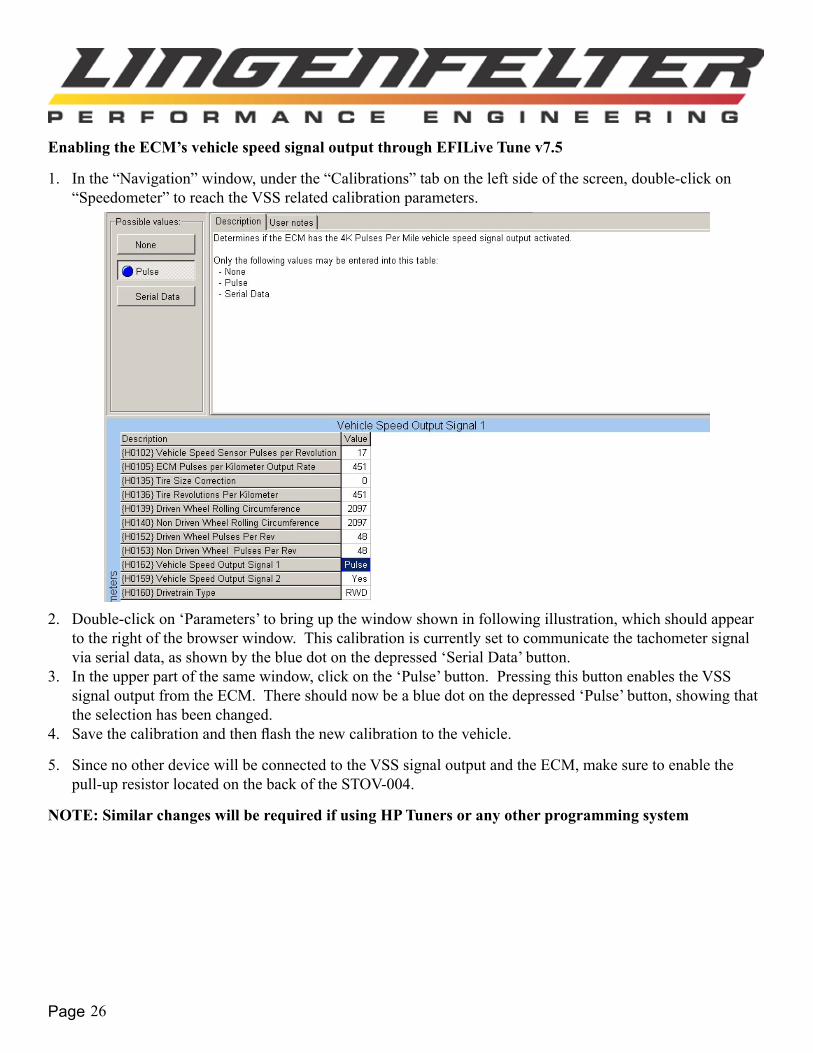
Enabling the ECM’s vehicle speed signal output through EFILive Tune v7.5
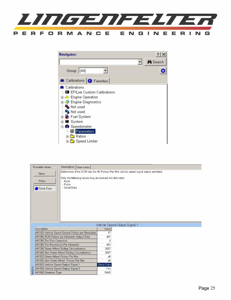
1. In the “Navigation” window, under the “Calibrations” tab on the left side of the screen, double-click on “Speedometer” to reach the VSS related calibration parameters.
2. Double-click on ‘Parameters’ to bring up the window shown in following illustration, which should appear to the right of the browser window. This calibration is currently set to communicate the tachometer signal via serial data, as shown by the blue dot on the depressed ‘Serial Data’ button.
3. In the upper part of the same window, click on the ‘Pulse’ button. Pressing this button enables the VSS signal output from the ECM. There should now be a blue dot on the depressed ‘Pulse’ button, showing that the selection has been changed.
4. Save the calibration and then flash the new calibration to the vehicle.
5. Since no other device will be connected to the VSS signal output and the ECM, make sure to enable the pull-up resistor located on the back of the STOV-004.
NOTE: Similar changes will be required if using HP Tuners or any other programming system

Page 27
Additional Notes and Warnings:• Changes to the switch settings must be done with the STOV-004 powered off.
• The switch positions are only read on start up (initial device power up).
• MakesurethattheSTOV-004groundwireissufficientlysecuredtoavehicleground.Failuretofullysecurethe STOV-004 ground wire to a vehicle ground source could cause the STOV-004 to malfunction.
• Do NOT submerge the module in liquid or directly wash the unit with liquid of any type. The switches on the STOV-004 are sealed but are NOT rated for high pressure washing, use caution if power washing near the STOV-004 module.
• Do NOT mount the STOV-004 directly on top of the engine or near the exhaust manifolds due to heat concerns.
• Do NOT mount the STOV-004 in the line of site of high temperature objects such as exhaust manifolds, turbine housings, etc... If needed, install a heat shield in between the heat source and the module to protect the plastic case.
• DoNOTinstallwithin6”ofnitroussolenoidsorotherdeviceswithstrongmagneticfields.
• Do NOT install near the spark plugs or the spark plug wires (or other potential strong sources of electrical noise).
• LPE recommends the use of resistor type spark plugs and RFI (radio frequency interference) and EMI (Electromagnetic Interference) suppression spark plug wires on all EFI engines and any vehicle that has electronic control modules on board (including the STOV-004). Failure to do so may result in erratic operation of electronic device
Troubleshooting:If you believe that the STOV-004 is switching at an incorrect vehicle speed, check the following:
• Verify that you are using the correct PPM for your vehicle.
• Reprogramming the STOV-004 may be necessary
If you are not receiving a speed signal, check the following:
• Verify that you are using a pull-up resistor if necessary (see page 5).
• Verify that you are using a correct vehicle speed output.

Page 28L460340004 STOV-004 MPH Activated Switch Instructions v1.3.indd
Limited Warranty:LPE warrants the Lingenfelter STOV-004 Speed Based Relay Control Module & Speed to Voltage Converter be free from defects in material and workmanship under normal use and if properly installed for a period of one year from the date of purchase. If the module is found to be defective as mentioned above, it will be replaced or repaired if returned prepaid along with proof of date of purchase. This shall constitute the sole remedy of the purchaser and the sole liability of LPE. To the extent permitted by law, the foregoing is exclusive and in lieu of all other warranties or representations whether expressedorimplied,includinganyimpliedwarrantyofmerchantabilityorfitness.InnoeventshallLPEbeliableforspecial or consequential damages.
Lingenfelter Performance Engineering1557 Winchester Road
Decatur, IN 46733(260) 724-2552
(260) 724-8761 faxwww.lingenfelter.com
NOTICES:It is the responsibility of the purchaser to follow all guidelines and safety procedures supplied with this product and any other manufacture’s product used with this product.
Lingenfelter Performance Engineering assumes no responsibility for damages resulting from accident, improper installation, misuse, abuse, improper operation, lack of reasonable care, or all previously stated reasons due to incompatibility with other manufacturer’s products.
Lingenfelter Performance Engineering assumes no responsibility or liability for damages incurred from the use of products manufactured or sold by Lingenfelter Performance Engineering on vehicles used for competition racing.
It is the purchaser’s responsibility to check the state and local laws and sanctioning body requirements pertaining to the use of this product for racing applications. Lingenfelter Performance Engineering does not recommend nor condone the use of its products for illegal street racing.
For additional product installation information and technical support, contact LPE or your LPE products distributor. You can also find technical support and usage discussions regarding this product and many other LPE products in our Internet forums:
http://www.lingenfelter.com/LPEforumfiles
Follow us on Facebook!
http://www.facebook.com/home.php#!/lpehp