Linear Residential Actuator Installation Guide
30
LRA Linear Residential Actuator Installation Guide Operator models contained in this manual conform to UL325 standard for use in Class I, II, III, and IV applications USA & Canada (800) 421-1587 & (800) 392-0123 (760) 438-7000 - Toll Free FAX (800) 468-1340 www.linearcorp.com
Transcript of Linear Residential Actuator Installation Guide

LRALinear Residential Actuator
Installation Guide
Operator models contained in this manual conform to UL325 standard for use in
Class I, II, III, and IV applications
USA & Canada (800) 421-1587 & (800) 392-0123(760) 438-7000 - Toll Free FAX (800) 468-1340
www.linearcorp.com

LRA Linear Residential Actuator Installation Guide 228158 Revision X17 8-11-2011
Table of Contents
Pre-installation Information . . . . . . . . . . . . . . . . . . . . . . . . . . . . . . . . . .1Before You Begin... . . . . . . . . . . . . . . . . . . . . . . . . . . . . . . . . . . . . . .1Always Check the Gate’s Action . . . . . . . . . . . . . . . . . . . . . . . . . . . .1Gate Operator Classifi cations . . . . . . . . . . . . . . . . . . . . . . . . . . . . . .1Approved Obstruction Detection Devices . . . . . . . . . . . . . . . . . . . . .1
Safety Information and Warnings . . . . . . . . . . . . . . . . . . . . . . . . . . . . . .1Regulatory Warnings . . . . . . . . . . . . . . . . . . . . . . . . . . . . . . . . . . . . .1
Linear Actuator Operator Overview . . . . . . . . . . . . . . . . . . . . . . . . . . . .2Wiring Specifi cations . . . . . . . . . . . . . . . . . . . . . . . . . . . . . . . . . . . . . . .2
AC Power Wiring . . . . . . . . . . . . . . . . . . . . . . . . . . . . . . . . . . . . . . . .2DC Control and Accessory Wiring . . . . . . . . . . . . . . . . . . . . . . . . . . .2
Control Box Mounting . . . . . . . . . . . . . . . . . . . . . . . . . . . . . . . . . . . . . . .2Gate Layout Illustration. . . . . . . . . . . . . . . . . . . . . . . . . . . . . . . . . . . . . .3Mounting Bracket Installation . . . . . . . . . . . . . . . . . . . . . . . . . . . . . . . .4
Universal Post Bracket Installation . . . . . . . . . . . . . . . . . . . . . . . . . .4Gate Bracket Installation . . . . . . . . . . . . . . . . . . . . . . . . . . . . . . . . . .4
Operator Setup . . . . . . . . . . . . . . . . . . . . . . . . . . . . . . . . . . . . . . . . . . . .5Operator Mounting . . . . . . . . . . . . . . . . . . . . . . . . . . . . . . . . . . . . . .5Controller Connection . . . . . . . . . . . . . . . . . . . . . . . . . . . . . . . . . . . .5AC Power Connection . . . . . . . . . . . . . . . . . . . . . . . . . . . . . . . . . . . .6Earth Ground . . . . . . . . . . . . . . . . . . . . . . . . . . . . . . . . . . . . . . . . . . .6Manual Disconnect . . . . . . . . . . . . . . . . . . . . . . . . . . . . . . . . . . . . . .6Dual Gate Stagger Delay . . . . . . . . . . . . . . . . . . . . . . . . . . . . . . . . . .6Limit Switch Adjustment . . . . . . . . . . . . . . . . . . . . . . . . . . . . . . . . . .8
Controller Features . . . . . . . . . . . . . . . . . . . . . . . . . . . . . . . . . . . . . . . . .9Indicator Descriptions . . . . . . . . . . . . . . . . . . . . . . . . . . . . . . . . . . . . . .10Terminal Descriptions . . . . . . . . . . . . . . . . . . . . . . . . . . . . . . . . . . . . . .11Operator Accessory Connections . . . . . . . . . . . . . . . . . . . . . . . . . . . .12Basic Controller Programming. . . . . . . . . . . . . . . . . . . . . . . . . . . . . . .13
Programming Overview . . . . . . . . . . . . . . . . . . . . . . . . . . . . . . . . . .13Entering Programming Mode . . . . . . . . . . . . . . . . . . . . . . . . . . . . .13Exiting Programming Mode . . . . . . . . . . . . . . . . . . . . . . . . . . . . . . .13Programming Keystrokes . . . . . . . . . . . . . . . . . . . . . . . . . . . . . . . .13Left or Right Hand Operation. . . . . . . . . . . . . . . . . . . . . . . . . . . . . .13Dual Gate Enable . . . . . . . . . . . . . . . . . . . . . . . . . . . . . . . . . . . . . .13Auto Close Timer . . . . . . . . . . . . . . . . . . . . . . . . . . . . . . . . . . . . . . .13Run Alarm and Pre-start Alarm . . . . . . . . . . . . . . . . . . . . . . . . . . . .14Maximum Open Direction Current Setting . . . . . . . . . . . . . . . . . . . .14Maximum Close Direction Current Setting . . . . . . . . . . . . . . . . . . .14
Advanced Controller Programming . . . . . . . . . . . . . . . . . . . . . . . . . . .15Entering Advanced Programming Mode . . . . . . . . . . . . . . . . . . . . .15Maximum Run Time . . . . . . . . . . . . . . . . . . . . . . . . . . . . . . . . . . . .15Single Button Input Setup . . . . . . . . . . . . . . . . . . . . . . . . . . . . . . . .15Auxiliary Relay Mode . . . . . . . . . . . . . . . . . . . . . . . . . . . . . . . . . . . .16Reverse Delay Time . . . . . . . . . . . . . . . . . . . . . . . . . . . . . . . . . . . .16Constant Pressure Mode . . . . . . . . . . . . . . . . . . . . . . . . . . . . . . . . .16Shadow Loop Open Prevention . . . . . . . . . . . . . . . . . . . . . . . . . . . .16Low Power Mode . . . . . . . . . . . . . . . . . . . . . . . . . . . . . . . . . . . . . . .17Power Failure Mode . . . . . . . . . . . . . . . . . . . . . . . . . . . . . . . . . . . . .17Soft Start/Stop Duration . . . . . . . . . . . . . . . . . . . . . . . . . . . . . . . . .17Reset Cycle Count . . . . . . . . . . . . . . . . . . . . . . . . . . . . . . . . . . . . .17Maintenance Alert Trigger . . . . . . . . . . . . . . . . . . . . . . . . . . . . . . . .18Mid-travel Stop Position . . . . . . . . . . . . . . . . . . . . . . . . . . . . . . . . . .18Anti-tailgate Enable . . . . . . . . . . . . . . . . . . . . . . . . . . . . . . . . . . . . .18Motor Type Selection . . . . . . . . . . . . . . . . . . . . . . . . . . . . . . . . . . . .18Radio Enable . . . . . . . . . . . . . . . . . . . . . . . . . . . . . . . . . . . . . . . . . .19Antenna Installation . . . . . . . . . . . . . . . . . . . . . . . . . . . . . . . . . . . . .19Radio Transmitter Learn . . . . . . . . . . . . . . . . . . . . . . . . . . . . . . . . .19Radio Transmitter Delete . . . . . . . . . . . . . . . . . . . . . . . . . . . . . . . . .19MGT Obstacle Transmitter Learn . . . . . . . . . . . . . . . . . . . . . . . . . .19MGT Obstacle Transmitter Delete . . . . . . . . . . . . . . . . . . . . . . . . . .19Reset Controller to Factory Defaults . . . . . . . . . . . . . . . . . . . . . . . .19
Loop Layout Illustration . . . . . . . . . . . . . . . . . . . . . . . . . . . . . . . . . . . .20Safety Edge Layout Illustration . . . . . . . . . . . . . . . . . . . . . . . . . . . . . .21Photoeye Installation Illustration . . . . . . . . . . . . . . . . . . . . . . . . . . . . .22Gate Operation . . . . . . . . . . . . . . . . . . . . . . . . . . . . . . . . . . . . . . . . . . . .23
Open Button . . . . . . . . . . . . . . . . . . . . . . . . . . . . . . . . . . . . . . . . . .23Close Button . . . . . . . . . . . . . . . . . . . . . . . . . . . . . . . . . . . . . . . . . .23Stop Button . . . . . . . . . . . . . . . . . . . . . . . . . . . . . . . . . . . . . . . . . . .23Single Input . . . . . . . . . . . . . . . . . . . . . . . . . . . . . . . . . . . . . . . . . . .23Fire Department Input . . . . . . . . . . . . . . . . . . . . . . . . . . . . . . . . . . .23Open Input . . . . . . . . . . . . . . . . . . . . . . . . . . . . . . . . . . . . . . . . . . . .23Open Obstruction . . . . . . . . . . . . . . . . . . . . . . . . . . . . . . . . . . . . . .23Close Obstruction . . . . . . . . . . . . . . . . . . . . . . . . . . . . . . . . . . . . . .23Reverse Input . . . . . . . . . . . . . . . . . . . . . . . . . . . . . . . . . . . . . . . . .23Open Loop . . . . . . . . . . . . . . . . . . . . . . . . . . . . . . . . . . . . . . . . . . . .23Reverse Loop . . . . . . . . . . . . . . . . . . . . . . . . . . . . . . . . . . . . . . . . .23Shadow/Reset Loop . . . . . . . . . . . . . . . . . . . . . . . . . . . . . . . . . . . .23
Operation Indications . . . . . . . . . . . . . . . . . . . . . . . . . . . . . . . . . . . . . .23Power-up Display . . . . . . . . . . . . . . . . . . . . . . . . . . . . . . . . . . . . . . .23Idle Condition . . . . . . . . . . . . . . . . . . . . . . . . . . . . . . . . . . . . . . . . .23Last Gate Position/Condition . . . . . . . . . . . . . . . . . . . . . . . . . . . . . .23Pre-start Delay . . . . . . . . . . . . . . . . . . . . . . . . . . . . . . . . . . . . . . . .23Reverse Delay . . . . . . . . . . . . . . . . . . . . . . . . . . . . . . . . . . . . . . . . .23Run Timer . . . . . . . . . . . . . . . . . . . . . . . . . . . . . . . . . . . . . . . . . . . .23
Error Indications . . . . . . . . . . . . . . . . . . . . . . . . . . . . . . . . . . . . . . . . . .24Entrapment . . . . . . . . . . . . . . . . . . . . . . . . . . . . . . . . . . . . . . . . . . .24MGT Obstacle Transmitter Trouble . . . . . . . . . . . . . . . . . . . . . . . . .24Maximum Run Time Exceeded . . . . . . . . . . . . . . . . . . . . . . . . . . . .24
Troubleshooting . . . . . . . . . . . . . . . . . . . . . . . . . . . . . . . . . . . . . . . . . . .25Contacting Technical Support . . . . . . . . . . . . . . . . . . . . . . . . . . . . .25Operator fails to start . . . . . . . . . . . . . . . . . . . . . . . . . . . . . . . . . . . .25Motor operates, but gate does not move . . . . . . . . . . . . . . . . . . . . .25Motor sounds like it is working harder than normal . . . . . . . . . . . . .25Gate stopping part way open or closed (but no visible obstruction) . . . . . . . . . . . . . . . . . . . . . . . . . . . . . . . .25Gate staying open with automatic system . . . . . . . . . . . . . . . . . . . .25How to Order Replacement Parts . . . . . . . . . . . . . . . . . . . . . . . . . .25
Model LRA Replacement Parts . . . . . . . . . . . . . . . . . . . . . . . . . . . . . .26Preventative Maintenance . . . . . . . . . . . . . . . . . . . . . . . . . . . . . . . . . .27
General . . . . . . . . . . . . . . . . . . . . . . . . . . . . . . . . . . . . . . . . . . . . . .27Lubrication . . . . . . . . . . . . . . . . . . . . . . . . . . . . . . . . . . . . . . . . . . . .276-Month Preventative Maintenance . . . . . . . . . . . . . . . . . . . . . . . . .27Battery Maintenance . . . . . . . . . . . . . . . . . . . . . . . . . . . . . . . . . . . .27
FCC Notice . . . . . . . . . . . . . . . . . . . . . . . . . . . . . . . . . . . . . . . . . . . . . . .27Gate Operator Installation Checklist . . . . . . . . . . . . . . . . . . . . . . . . . .28
ONLY QUALIFIED TECHNICIANSSHOULD WORK ON
LINEAR RESIDENTIALACTUATORS
WARNING
WARNING
CONTROLS INTENDED FOR USER ACTIVATION MUST BE LOCATED AT LEAST SIX FEET (6') AWAY FROM ANY MOVING PART OF THE GATE AND WHERE THE USER IS PREVENTED FROM REACHING OVER, UNDER, AROUND OR THROUGH THE GATE TO OPERATE THE CONTROLS. OUTDOOR OR EASILY ACCESSIBLE CONTROLS SHALL HAVE A SECURITY FEATURE TO PREVENT UNAUTHORIZED USE.

LRA Linear Residential Actuator Installation Guide - 1 - 228158 Revision X17 8-11-2011
Pre-installation Information
Before You Begin...Before unpacking, inspect the carton for exterior damage. If you fi nd damage, advise the delivery carrier of a potential claim. Inspect your package carefully. You can check your accessory box parts with the enclosed packing slip for your convenience. Claims for shortages will be honored for only 30 days from the date of shipment.
Before installing the operator, read this manual completely to ensure all requirements for proper installation are present. Verify that the voltage to be used matches the voltage of the operator.
If you have any questions about the requirements for proper installation of this gate operator contact technical support at 800-421-1587.
Always Check the Gate’s ActionIt’s very important before installing the gate operator to make sure the gate’s swing is free and level throughout the entire swing path. If the gate does not seem to operate properly, it may affect the operator performance or greatly shorten the life of the unit. The gate should also be designed so that airfl ow is ample to prevent wind resistance and drag.
Gate Operator Classifi cationsAll gate operators can be divided into one of four different classifi cations, depending on their design and usage. Install this gate operator only when the operator is appropriate for the construction and usage class as defi ned below:
• Class I Residential Vehicular Gate OperatorA vehicular gate operator intended for use in a home or for one to four single family dwellings with a common garage or parking area associated with these dwellings.
• Class II Commercial / General Access Vehicular Gate OperatorA vehicular gate operator intended for use in a commercial location or building such as a multi-family housing unit of fi ve or more single family units, hotel, retail store or other building servicing the general public.
• Class III Industrial / Limited Access Vehicular Gate OperatorA vehicular gate operator intended for use in an industrial location or building such as a factory or loading dock area or other location not intended to service the general public.
• Class IV Restricted Access Vehicular Gate OperatorA vehicular gate operator intended for use in a guarded industrial location or building such as an airport security area or other restricted access locations not servicing the general public, in which unauthorized access is prevented via supervision by security personnel.
Approved Obstruction Detection DevicesThe following contact or non-contact obstruction detection devices have been approved for use with Linear’s Residential Actuators as part of a UL325 compliant installation:
• Contact EdgesMiller Edge Models MGO20, MGR20, MGS20, ME120
• PhotoeyesMMTC Model IR-55 (165’ range - P/N 2520-441)MMTC Model E3K (28’ range - P/N 2520-031)
Safety Information and Warnings
Regulatory WarningsRead the following before beginning to install Linear’s Residential Actuators:
THE FOLLOWING FORMATS ARE USED FOR SAFETY NOTESIN THESE INSTRUCTIONS.
WARNING This type of warning note is used to indicate possible mechanical hazards that may cause serious injuries or death.
CAUTION This type of warning note is used to indicate the possibility of damage to the gate or gate operator.
WARNING This type of warning note is used to indicate possible electrical shock hazards that may cause serious injuries or death.
IMPORTANT INSTALLATION SAFETY INSTRUCTIONS WARNING
TO REDUCE THE RISK OF SEVERE INJURY OR DEATH TO PERSONS, REVIEW THESE INSTALLATION SAFETY
STEPS BEFORE PROCEEDING 1. READ AND FOLLOW ALL INSTALLATION INSTRUCTIONS. 2. Read the yellow “Safety Instructions” brochure enclosed with the
packet of information. If any pages are missing or are unreadable, or you do not have the safety instructions, please call Linear at 1-800-421-1587 to request additional copies.
3. ALL ELECTRICAL CONNECTIONS TO THE POWER SUPPLY MUST BE MADE BY A LICENSED ELECTRICIAN AND MUST OBSERVE ALL NATIONAL AND LOCAL ELECTRICAL CODES.
4. A separate power-disconnect switch should be located near the operator so that primary power can be turned off when necessary.
5. Install the enclosed warning signs on both sides of the gate. A minimum of two (2) WARNING SIGNS shall be installed, one on each side of the gate where easily visible.
6. Never reach between, through or around the fence to operate the gate.
7. Never connect a button station within reach of the gate or on the side of the gate operator.
8. Do not adjust the operator controller’s current sensing feature too high. It should be adjusted high enough to keep the gate from falsely triggering the sensing, but no higher than necessary for the gate to operate. DO NOT DEFEAT THE PURPOSE OF THIS FUNCTION!
9. You must install all required safety equipment. 10. UL325 Compliance requires the use of contact edges or photoelectric
controls on all automatic or remotely-controlled gate operators. 11. The operator is intended for installation only on gates used for
vehicles. Pedestrians must be supplied with a separate access opening. The pedestrian access opening shall be designed to promote pedestrian usage. Locate the gate such that persons will not come into contact with the vehicular gate during the entire path of travel of the vehicular gate.
LRA Linear Residential Actuator Installation Guide - 2 - 228158 Revision X17 8-11-2011
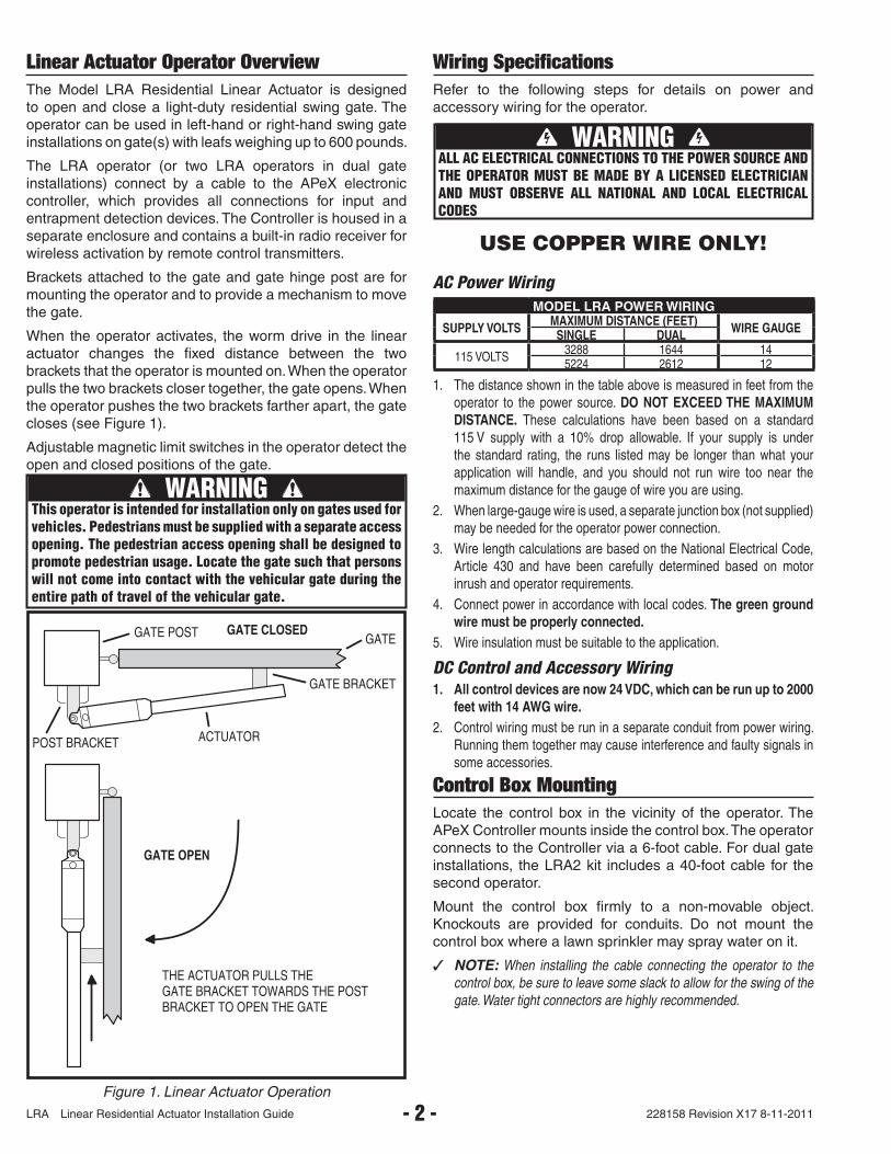
Linear Actuator Operator OverviewThe Model LRA Residential Linear Actuator is designed to open and close a light-duty residential swing gate. The operator can be used in left-hand or right-hand swing gate installations on gate(s) with leafs weighing up to 600 pounds.
The LRA operator (or two LRA operators in dual gate installations) connect by a cable to the APeX electronic controller, which provides all connections for input and entrapment detection devices. The Controller is housed in a separate enclosure and contains a built-in radio receiver for wireless activation by remote control transmitters.
Brackets attached to the gate and gate hinge post are for mounting the operator and to provide a mechanism to move the gate.
When the operator activates, the worm drive in the linear actuator changes the fi xed distance between the two brackets that the operator is mounted on. When the operator pulls the two brackets closer together, the gate opens. When the operator pushes the two brackets farther apart, the gate closes (see Figure 1).
Adjustable magnetic limit switches in the operator detect the open and closed positions of the gate.
Wiring Specifi cationsRefer to the following steps for details on power and accessory wiring for the operator.
AC Power WiringMODEL LRA POWER WIRING
SUPPLY VOLTS MAXIMUM DISTANCE (FEET) WIRE GAUGESINGLE DUAL
115 VOLTS 3288 1644 145224 2612 12
1. The distance shown in the table above is measured in feet from the operator to the power source. DO NOT EXCEED THE MAXIMUM DISTANCE. These calculations have been based on a standard 115 V supply with a 10% drop allowable. If your supply is under the standard rating, the runs listed may be longer than what your application will handle, and you should not run wire too near the maximum distance for the gauge of wire you are using.
2. When large-gauge wire is used, a separate junction box (not supplied) may be needed for the operator power connection.
3. Wire length calculations are based on the National Electrical Code, Article 430 and have been carefully determined based on motor inrush and operator requirements.
4. Connect power in accordance with local codes. The green ground wire must be properly connected.
5. Wire insulation must be suitable to the application.
DC Control and Accessory Wiring1. All control devices are now 24 VDC, which can be run up to 2000
feet with 14 AWG wire.2. Control wiring must be run in a separate conduit from power wiring.
Running them together may cause interference and faulty signals in some accessories.
Control Box MountingLocate the control box in the vicinity of the operator. The APeX Controller mounts inside the control box. The operator connects to the Controller via a 6-foot cable. For dual gate installations, the LRA2 kit includes a 40-foot cable for the second operator.
Mount the control box fi rmly to a non-movable object. Knockouts are provided for conduits. Do not mount the control box where a lawn sprinkler may spray water on it.
✓ NOTE: When installing the cable connecting the operator to the control box, be sure to leave some slack to allow for the swing of the gate. Water tight connectors are highly recommended.
WARNING ALL AC ELECTRICAL CONNECTIONS TO THE POWER SOURCE AND THE OPERATOR MUST BE MADE BY A LICENSED ELECTRICIAN AND MUST OBSERVE ALL NATIONAL AND LOCAL ELECTRICAL CODES
USE COPPER WIRE ONLY!
WARNING This operator is intended for installation only on gates used for vehicles. Pedestrians must be supplied with a separate access opening. The pedestrian access opening shall be designed to promote pedestrian usage. Locate the gate such that persons will not come into contact with the vehicular gate during the entire path of travel of the vehicular gate.
GATE POST GATE
ACTUATOR
GATE CLOSED
GATE OPEN
THE ACTUATOR PULLS THEGATE BRACKET TOWARDS THE POSTBRACKET TO OPEN THE GATE
GATE BRACKET
POST BRACKET
Figure 1. Linear Actuator Operation

LRA Linear Residential Actuator Installation Guide - 3 - 228158 Revision X17 8-11-2011
Gate Layout Illustration
ENTR
Y
GAT
E FU
LLY
CLO
SED
GAT
E FU
LLY
OPE
N
LEAV
E SL
ACK
IN C
ABLE
TO
ALLO
W F
OR
GAT
E SW
ING
1/2
GAT
EH
EIG
HT
CO
NTR
OL
BOX
CO
NTR
OL
BOX
GAT
E TO
P VI
EW
GAT
E BA
CK S
IDE
VIEW
36"
REC
OM
MEN
DED
MIN
IMU
M B
ACKS
PAC
E8"
FR
OM
CEN
TER
OF
GAT
E H
ING
E
RO
ADW
AY
POST
OR
PILL
AR
POST
OR
PILL
AR
EXIT
GAT
E H
ING
E
LRA
ACTU
ATO
R
LRA
ACTU
ATO
R IN
CLO
SED
PO
SITI
ON
LRA
ACTU
ATO
R IN
OPE
N P
OSI
TIO
NLE
FT H
AND
GAT
E O
PERA
TIO
NSH
OW
N

LRA Linear Residential Actuator Installation Guide - 4 - 228158 Revision X17 8-11-2011
Mounting Bracket InstallationExamine Figure 2 for details on the required mounting locations for the brackets. They must be mounted at the correct locations to allow the operator to open the gate at a 90 degree angle and to ensure the operator functions smoothly.
The brackets must also be mounted level in respect to each other so the operator’s front and rear mounting points are vertical and not offset at an angle.
1. Measure approximately halfway up the gate height and determine good strong spots located in the required areas to mount the brackets on the post and gate.
2. Using Figure 2 as a guide, mark the locations on the post or pillar and the gate for the mounting brackets. The top surface of the post bracket must be 3/8” below the top surface of the gate bracket to allow for the bolt-on operator bracket’s 3/8” thickness.
✓ NOTE: Depending on the gate design, an additional reinforcing plate welded to the gate may be required to provide a good spot to mount the gate bracket.
Universal Post Bracket Installation✓ NOTE: When installing the post bracket on a round post or masonry
pillar, use improvised methods (additional plate with lag bolts and anchors, concrete wedge anchors, U-bolts, etc.) to securely fasten the bracket.
1. Tack weld the post bracket to the post at the marked spot and double-check its level and height.
2. Finish welding the post bracket to the gate post and allow the weld to cool.3. Attach the bolt-on operator bracket to the post bracket at the correct
depth and angle using three bolts and locknuts (there are 18 possible positions). Install the operator bracket pin as shown in Figure 3.
Gate Bracket InstallationBefore welding the gate bracket, be sure the centers of the operator mounting holes on the brackets will end up 29-1/2” apart when the gate is fully closed.
1. Tack weld the gate bracket to the gate at the marked spot and double-check its level and height.
2. Finish welding the gate bracket to the gate.3. After the welding is completed and the gate bracket has cooled,
snap the limit switch magnet assembly onto the gate bracket (see Figure 4).
4. From the top side of the gate bracket, slide the load bushing into the bracket hole.
Alternate method to locate the gate bracket:
1. Hold the gate bracket with the magnets installed onto the LRA traveler.2. Run the unit to the full open position.3. Place the rear of the arm onto the post bracket.4. Manually fully open the gate.5. Position the gate bracket in the required position.6. Remove the magnet assembly and bolt or weld the bracket in place.
Figure 2. Required Bracket Locations
Figure 4. Gate Bracket Installation
WELD GATE BRACKETTO GATE
SNAP MAGNETASSEMBLY ONTOGATE BRACKETAFTER WELDING
USE ALEVEL
29-1/2"
6"
5-1/2"
LOCATE POST BRACKET AT THESEDIMENSIONS FROM THE GATE CENTERLINE AND HINGE POINT
SETTING THE BRACKETS AT THISDISTANCE WILL CAUSE THE GATETO OPEN AT 90 DEGREES (DEPENDINGON THE LIMIT SWITCH SETTINGS)
NOTE: THE 5-1/2" AND6" DIMENSIONS ARECRITICAL FOR PROPERGATE OPERATION
WELD POST BRACKETTO POST
ASSEMBLE OPERATORBRACKET PIN WITHTHICK SPACER ON PIN
ATTACH OPERATORBRACKET TO POSTBRACKET AT PROPERLOCATION WITHTHREE BOLTS ANDLOCKNUTS
Figure 3. Post Bracket Installation
WARNING The gate must be installed in a location so that enough clearance is supplied between the gate and adjacent structures when opening and closing to reduce the risk of entrapment. Swing gates shall not open into public areas.

LRA Linear Residential Actuator Installation Guide - 5 - 228158 Revision X17 8-11-2011
Operator Setup
Operator MountingThe operator mounts on the post bracket pin and into the gate bracket bushing. Refer to Figure 5.
1. With the gate closed, carefully position the operator over the mounting brackets.
2. Lower the operator onto the post bracket pin while guiding the operator’s worm drive traveler shaft into the gate bracket bushing.
3. Install the washer and clip-ring on the post bracket pin.4. Install the washer and clip-ring on the traveler shaft.
Controller ConnectionThe APeX Controller is mounted in a sealed NEMA4 enclosure. Open the cover for installation access.
The Controller contains two 5-position plug-in terminal blocks for connection to one or two LRA operators. Terminal block MOTOR-1 is used in single gate LRA installations. Terminal block MOTOR-2 is used for the second arm in dual gate LRA2 installations.
To make wiring easy, the terminal blocks are removable and plug into the Controller’s circuit board.
1. Route the operator cable up through the fl uid-tight strain-relief fi tting on the bottom of the Controller’s cabinet.
2. Noting the wire colors, connect the operator cable to MOTOR-1 Terminals 1-5 on the Controller.
3. Route the cable towards the operator. Be sure to leave enough slack in the cable to allow for the gate swing.
4. Remove the operator’s wiring access plate (see Figure 6).5. Cut the cable to length if required, then slide the O-ring over the end
of the cable.6. Connect the interface cable to the operator’s terminal block matching
the same colors and terminal numbers used in Step 2 (see Figure 6).7. Replace the operator’s wiring access plate being careful to align the
O-ring below the cable clamp. The O-ring helps keep out moisture.For dual gate installations, repeat Steps 1-7 and connect the second operator’s cable to the MOTOR-2 5-position terminal block in the Controller (see Figure 7). Use the strain-relief fi tting that comes with the LRA2 kit where the cable enters the Controller cabinet.
TRAVELERSHAFT
GATE BRACKETBUSHING
WASHERAND CLIP-RING
Figure 5. Mounting the Operator
Figure 6. Operator Cable Connections
Figure 7. Controller Cable Connections
12
34
5 5 - OPEN LIMIT4 - COMMON (LIMIT)3 - CLOSE LIMIT2 - MOTOR1 - MOTOR
MATCH TERMINAL NUMBERSON OPERATOR & CONTROLLER
PUT O-RING ON CABLE TOSEAL OUT MOISTURE
O-RINGFITS
IN SLOT
MOTOR 1 TERMINALS MOTOR 2 TERMINALS
TO LRA ARM #1
TO LRA ARM #2
1
2
3
45
5
4
3
21
FOR STAGGERED GATE INSTALLATIONS,ONLY THE MOTOR 1 CONNECTION CAN BEDELAYED ON OPENING. PLUG THE ARM TOBE DELAYED INTO THE MOTOR 1 TERMINALS.
MOTOR 1 MOTOR 21 2 3 4 5 1 2 3 4 5

LRA Linear Residential Actuator Installation Guide - 6 - 228158 Revision X17 8-11-2011
Operator Setup (Continued)
AC Power ConnectionThe control box contains a power disconnect switch to turn on and off the power available to the operator. Following wiring specifi cations on Page 2, incoming power should be brought into the control box and connected to the labeled pigtails from the disconnect box. A wiring connections print can be found on the label inside the cover of the operator. See Figure 8 for power option examples.
Earth GroundInstall a ground rod and connect it to the control box in every installation. A good earth ground is necessary to allow the Controller’s built-in surge and lightning protection circuitry to work effectively.
✓ NOTE: Do not splice the ground wire. Use a single piece of solid copper 12 AWG wire between the ground rod and the control box.
1. Install an 8-foot long copper ground rod within three feet of the control box.
2. Use a clamp to connect a solid copper 12 AWG ground wire to the ground rod.
3. Route the ground wire to the control box through a wiring knockout.4. Connect the ground wire to the screw terminal located above the
115V power receptacle on the Controller’s metal chassis.
Manual DisconnectIn case of a power failure or other condition, the gate can be manually moved without action from the operator by using the manual disconnect switch (see Figure 9).
To activate the manual disconnect switch:
1. Open the cover on the switch.2. Insert the disconnect key (supplied with operator).3. Turn the key clockwise 90˚.4. Reverse the steps to re-engage the operator.
Dual Gate Stagger DelayThis feature is used for overlapping dual gates. After completing setup of the operator, in dual gate installations use the following control to adjust the dual gate stagger:
To delay opening of Gate 1, and delay closing of Gate 2, gently adjust the potentiometer located on the motor board (under the small blue removable cover) clockwise until the desired delay is reached (see Figure 10). Do not turn more than ¾ of a turn or damage will result. Range is 0 to 10 seconds delay.
Only Motor-1 can be delayed on open. Plug the appropriate LRA arm into either the MOTOR-1 or MOTOR-2 terminal block to change which gate is delayed.
DISCONNECT(UNLOCK)
CONNECT(LOCK)
MANUAL DISCONNECTCAN BE USED TODISENGAGEOPERATOR
STAGGER DELAY ADJUSTMENT(ON MOTOR CONTROLLER BOARD
UNDER BLUE COVER)
MOREDELAY
LESSDELAY
Figure 9. Manual Disconnect
Figure 10. Stagger Delay Control
WARNING ALL AC ELECTRICAL CONNECTIONS TO THE POWER SOURCE AND THE OPERATOR MUST BE MADE BY A LICENSED ELECTRICIAN AND MUST OBSERVE ALL NATIONAL AND LOCAL ELECTRICAL CODES.
CONTROL BOX
GREEN - GROUNDWHITE - NEUTRALBLACK - HOT
BRING 115V HOT, NEUTRAL, ANDGROUND INTO CONTROL BOX ANDCONNECT TO AC POWER FLYING LEADS
115V POWERRECEPTACLE
GROUNDSCREW
POWER KNOCKOUTON CABINET BOTTOM
AC POWER MUST BE CONNECTEDBY A LICENSED ELECTRICTIAN
Figure 8. Power and Ground Connections

LRA Linear Residential Actuator Installation Guide - 7 - 228158 Revision X17 8-11-2011

LRA Linear Residential Actuator Installation Guide - 8 - 228158 Revision X17 8-11-2011
Operator Setup (Continued)
Limit Switch AdjustmentThe open and close limit switches are adjustable by sliding them on the operator’s frame. Sliding either switch closer to the center of the operator decreases the gate travel.
1. To limit the opening travel of the gate for setup, loosen the locking screw on the open limit switch, slide the switch towards the center of the operator (see Figure 11).
2. With the gate closed, apply power to the Controller, STAY CLEAR OF THE GATE and press the OPEN button.
3. Observe the gate as it opens, and watch the point where it stops.4. To limit the closing travel of the gate for setup, loosen the locking
screw on the close limit switch, remove the wire holding plugs from the wire slot in the channel, slide the switch towards the center of the operator (see Figure 12).
5. Be sure to STAY CLEAR OF THE GATE and press the CLOSE button.
6. Observe the gate as it closes, and watch the point where it stops.7. Adjust the two limit switches until the open and close stopping points
are set correctly for the gate. TIGHTEN THE LOCKING SCREWS ON THE LIMIT SWITCHES.
8. Push any extra limit wire back into the motor housing. Replace the limit switch wire holding plugs to retain the limit switch wire.
SLIDE OPEN LIMIT SWITCHTO ADJUST OPEN LIMIT
LIMIT SWITCH LOCKING SCREW
OPEN LIMIT SWITCH
Figure 11. Open Limit Switch
Figure 12. Close Limit Switch
SLIDE CLOSE LIMIT SWITCHTO ADJUST CLOSE LIMIT
LIMIT SWITCHLOCKING SCREW
CLOSE LIMIT SWITCH
REMOVE AND REPLACELIMIT WIRE PLUG DURINGLIMIT SWITCH ADJUSTMENT
CAUTION Be careful not to damage the limit switch wires while adjusting the limit switches. Gently pull the limit switch wire while tightening the limit switch locking screw (see Figure 12).
AVOID PINCHING THE LIMIT SWITCHWIRE BY GENTLY PULLING IT WHILETIGHTENING THE LIMIT SWITCH
Figure 13. Limit Switch Wire

LRA Linear Residential Actuator Installation Guide - 9 - 228158 Revision X17 8-11-2011
Controller Features
SHADOW/RESET
PROGRAMMINGBUTTONS
POWERINDICATORS
DISPLAY
WHIPANTENNA
OPERATIONBUTTONS
OPERATION ANDPROGRAMMING
INDICATORS
ANTENNACONNECTOR
MOTORBOARDCOVER
INPUTPOWER
TERMINALS
ACCESSORYPOWER
TERMINALS
RESETBUTTON
TERMINALS
SOLARPANEL
TERMINALS
BATTERYTERMINALS
PLUG-INLOOP
DETECTORCONNECTORS
PRIMARY/SECONDARYCOMM LINKTERMINALS
SINGLEINPUT
TERMINALS
FIRE DEPTINPUT
TERMINALS
OPEN INPUTTERMINALS
3-BUTTONSTATION
TERMINALS
OPEN AND CLOSEOBSTRUCTION
INPUT TERMINALS REVERSEINPUT
TERMINALSOPEN LOOP
INPUT TERMINALS
REVERSE LOOPINPUT TERMINALS
SHADOW/RESET LOOPINPUT TERMINALS
LIMIT SWITCHINPUT TERMINALS
ALARMOUTPUT
TERMINALS
AC MOTOROUTPUT
TERMINALS
AUXILIARYRELAY
TERMINALS
Figure 14. Controller Features

LRA Linear Residential Actuator Installation Guide - 10 - 228158 Revision X17 8-11-2011
Indicator Descriptions
INDICATOR DEFINITION INDICATION WHEN LITDURING NORMAL OPERATION
INDICATION WHEN LITDURING PROGRAMMINGOPERATION PROGRAMMING
24 VOLT INPUT POWER
LOW VOLTAGE AC POWER IS PRESENT
24 VOLT DC ACCY POWER
LOW VOLTAGE DC POWER IS PRESENT
OPENOPEN SIGNAL PRESENT FROM THE INTERNAL RECEIVER OR AN EXTERNAL DEVICE CONNECTED TO THE OPEN INPUT TERMINAL
CLOSECLOSE SIGNAL IS PRESENT FROM A DEVICE CONNECTED TO THE CLOSE INPUT TERMINAL
STOPSTOP INPUT TERMINAL IS OPEN AND NOT CONNECTED TO COMMON
PROGRAM CONTROLLER IS IN PROGRAMMING MODEREVERSE DELAY SET SIGNAL FROM REVERSING DEVICE IS PRESENT SET REVERSE DELAY TIME
LOCKOUT ALARM SETCONTROLS AND OPERATOR ARE LOCKED OUT BECAUSE OF EXISTING TROUBLE CONDITION
SET RUN ALARM AND PRE-START ALARM
RADIO LEARNBUILT-IN RECEIVER IS DETECTING A RADIO SIGNAL FROM A REMOTE CONTROL
TRANSMITTERS CAN BE ENTERED INTO MEMORY (UP TO 40 TRANSMITTERS)
OPEN CURRENT SETMOTOR CURRENT HAS EXCEEDED THE OPEN CURRENT SETTING WHILE OPENING
SET MAXIMUM OPEN CURRENT
OPEN OBSTR MGT 2 SETOPEN OBSTRUCTION TERMINAL CONNECTED TO COMMON BY BEAM OR SAFETY EDGE, OR SIGNAL FROM MGT OBSTACLE TRANSMITTER
SET MGT #2 FUNCTION
OPEN RELAY OPEN RELAY IS ACTIVATEDOPEN LIMIT BRAKE DELAY OPEN LIMIT SWITCH IS ACTIVATED
CLOSE CURRENT SETMOTOR CURRENT HAS EXCEEDED THE CLOSE CURRENT SETTING WHILE CLOSING
SET MAXIMUM CLOSE CURRENT
CLOSE OBSTR MGT 1 SETCLOSE OBSTRUCTION TERMINAL CONNECTED TO COMMON BY BEAM OR SAFETY EDGE, OR SIGNAL FROM MGT OBSTACLE TRANSMITTER
SET MGT #1 FUNCTION
CLOSE RELAY AUTO CLOSE SET CLOSE RELAY IS ACTIVATED SET AUTO-CLOSE TIMECLOSE LIMIT CLOSE LIMIT SWITCH IS ACTIVATED
SINGLE SETSINGLE TERMINAL CONNECTED TO COMMON BY AN EXTERNAL PUSHBUTTON OR RADIO
SET SINGLE BUTTON INPUT FUNCTION
MAX RUN SET MAXIMUM RUN TIMER HAS BEEN EXCEEDED SET MAXIMUM RUN TIME
COMM LINK SETNOT USED IN SINGLE OR DUAL GATE LRA INSTALLATIONS
MAINT ALERT SET MAINTENANCE IS REQUIRED ON OPERATOR SET MAINTENANCE ALERT CYCLE COUNT
"RL" LEFT OR RIGHTHAND OPERATION
"PM" SINGLE ORDUAL GATE
"AC" AUTO CLOSETIMER
"RP" RUN ALARMPRE-START ALARM
"OC" MAXIMUM OPENCURRENT
"CC" MAXIMUM CLOSECURRENT
"AD"ADVANCED PROGRAMMING
"RT" MAXIMUMRUN TIMER
"SB"SINGLE BUTTONINPUT SETUP
"AR" AUXILIARYRELAY MODE
"RD" REVERSEDELAY TIME
"LP"LOW POWERMODE
POWERFAILURE MODE"FS"
"SS" SOFT START/STOPDURATION
"CT" RESET CYCLECOUNT
"MA"MAINTENANCE ALERTTRIGGER
"MT" MID-TRAVELSTOP POSITION
"RA"RADIOENABLE
"TL" LEARNTRANSMITTERS
"TD"DELETETRANSMITTERS
"ML"LEARN MGTTRANSMITTERS
"MD"ERASE MGTTRANSMITTERS
"CL"RESET TOFACTORY DEFAULTS
APEX FUNCTION DISPLAY INDICATIONS
MOTOR TYPESELECTION"MO"
"CP" CONSTANTPRESSURE MODE
"SP" SHADOW LOOPOPEN INHIBIT
"AT" ANTI-TAILGATEENABLE

LRA Linear Residential Actuator Installation Guide - 11 - 228158 Revision X17 8-11-2011
Terminal Descriptions
TERMINAL GROUP FUNCTION
AC N24 VOLT INPUT
FACTORY CONNECTED TO 24 VAC FROM TRANSFORMER OR 24 VDC FROM CONTINUOUS DUTY DC SUPPLY.AC
DC -ACCESSORY POWER PROVIDES 24 VOLT DC POWER FOR ACCESSORIES. (.5A MAX)
DC +
RESETRESET BUTTON FACTORY CONNECTED TO THE CONTROLLER’S RESET BUTTON.
COMMON
C
COMM LINK NOT USED IN SINGLE OR DUAL GATE LRA INSTALLATIONS.B
A
COMMONSINGLE BUTTON INPUT
CONNECT TO NORMALLY OPEN SWITCH FOR SINGLE BUTTON OPERATION. ALTERNATES BETWEEN OPEN-CLOSE OR OPEN-STOP-CLOSE DEPENDING ON PROGRAMMING.SINGLE
COMMONFIRE BOX INPUT CONNECT TO NORMALLY OPEN SWITCH IN FIRE BOX FOR FIRE DEPARTMENT ACCESS.
FIRE DEPT
COMMONOPEN INPUT
CONNECT TO NORMALLY OPEN DEVICES (KEYPAD, CARD READER, KEYSWITCH, TELEPHONE ENTRY SYSTEM) TO OPEN THE GATE. A CONSTANT OPEN INPUT WILL OVERRIDE THE MID-TRAVEL STOP AND HALT THE AUTO CLOSE TIMER UNTIL RELEASED.OPEN
OPEN
3-BUTTON STATION INPUT
CONNECT TO 3-BUTTON STATION FOR OPEN-CLOSE-STOP CONTROL. A CONSTANT OPEN INPUT WILL OVERRIDE THE MID-TRAVEL STOP AND HALT THE AUTO CLOSE TIMER UNTIL RELEASED.
CLOSE
COMMON
STOP
COM
OBSTRUCTION INPUTS
CONNECT TO NORMALLY OPEN DEVICES (GATE EDGE, PHOTO BEAM) TO DETECT AN OBSTRUCTION DURING OPENING. WHILE GATE IS IN MOTION, ANY OPEN OBSTRUCTION SIGNAL WILL CAUSE THE GATE TO STOP, REVERSE A SHORT DISTANCE, AND THEN STOP AGAIN. AT THIS TIME THE AUTO CLOSE TIMER IS DISABLED, AND A RENEWED INPUT WILL BE REQUIRED TO START THE GATE AGAIN. SHOULD THE GATE BE RESTARTED AND THE OBSTACLE SIGNAL OCCUR AGAIN PRIOR TO REACHING A LIMIT, THE GATE WILL STOP AGAIN, LOCKOUT, AND SOUND THE EMERGENCY ALARM.
O-OBS
C-OBSFUNCTIONS THE SAME AS THE OPEN OBSTRUCTION, EXCEPT IN THE CLOSING DIRECTION.
COM
COMREVERSE
CONNECT TO NORMALLY OPEN DEVICES TO CAUSE A REVERSAL WHEN THE GATE IS TRAVELING CLOSED. THE GATE WILL REVERSE TO THE FULL OPEN POSITION.REV
OPEN LOOPOPEN LOOP
CONNECT TO OPEN LOOP/FREE EXIT LOOP. THE GATE WILL OPEN WHEN THE LOOP IS TRIGGERED, AND REMAIN OPEN AS LONG AS THE LOOP IS TRIGGERED. REQUIRES LOOP DETECTOROPEN LOOP
REVERSE LOOPREVERSE LOOP
CONNECT TO REVERSE LOOP. TRIGGERING THE LOOP WILL CAUSE A REVERSAL WHEN THE GATE IS TRAVELING CLOSED. THE GATE WILL REVERSE TO THE FULL OPEN POSITION.. REQUIRES LOOP DETECTORREVERSE LOOP
SHADOW/RESET LOOPSHADOW/RESET LOOP
CONNECT TO SHADOW/RESET LOOP TO KEEP THE GATE IN ITS FULLY OPEN POSITION AS LONG AS THE SIGNAL IS PRESENT. USED TO KEEP GATE OPEN WHILE VEHICLE IS PASSING THROUGH.. REQUIRES LOOP DETECTORSHADOW/RESET LOOP
-ALARM FACTORY CONNECTED TO THE ALARM BEEPER.
+
N.O.
AUX RELAYFOR CONNECTION TO AUXILIARY DEVICES (MAGNETIC LOCK, SOLENOID LOCK, STROBE LIGHT) FOR ACTIVATION (OR DEACTIVATION) DURING GATE OPERATION.
COM
N.C.
+24 VOLT SOLAR PANEL FOR CONNECTION TO 24 VOLT SOLAR PANEL FOR BATTERY CHARGING.
-
+24 VOLT BATTERY FACTORY CONNECTED TO BATTERIES IN DC MODEL OPERATORS.
-

LRA Linear Residential Actuator Installation Guide - 12 - 228158 Revision X17 8-11-2011
Operator Accessory Connections3-BUTTON STATION
KEYSWITCH
FIRE ACCESS SWITCH
SINGLE-CHANNEL RADIO RECEIVER
WIRELESS GATE EDGE SENSOR
MGTTRANSMITTER
PHOTOEYE FOR REVERSE
PHOTOEYE FOR OPEN OBSTRUCTION
TELEPHONE ENTRY
KEYPAD
EXTERNAL POWER
SOLENOID LOCK
MAGLOCK
WARNING STROBE OR AUDIBLE SOUNDER
GATE EDGE SENSOR FOR REVERSE
CHANNEL #1OPEN/CLOSE
TWO-CHANNEL RADIO RECEIVER
PHOTOEYE FOR CLOSE OBSTRUCTION
Figure 15. Operator Accessory Connections

LRA Linear Residential Actuator Installation Guide - 13 - 228158 Revision X17 8-11-2011
Basic Controller Programming
Programming OverviewThe Controller can be programmed with various options for the operator. The programming fi elds are defi ned as “functions” that have “options”. To make setup easier for the installer, the Controller’s programming is divided into two groups: basic and advanced. The basic programming group contains the functions commonly used in most swing gate installations. The advanced programming group contains functions less commonly used (i.e. maximum run timer, etc.).
Entering Programming ModeEnter programming mode by pressing the UP and DOWN buttons together for one second. While in programming mode the PROGRAM indicator will light.
Exiting Programming ModeExit programming mode at any time by pressing the UP and DOWN buttons together. The Controller will automatically exit programming mode after three minutes of inactivity.
Programming Keystrokes(Typical Programming Method)
While in programming mode, press the UP or DOWN buttons to scroll through the programming functions. When the desired function is displayed press the ENTER button to display the currently set option for the function. When an option is displayed, the decimal points are lit.
To change the option, press and hold the ENTER button for 1 second. To indicate that an option is ready to be changed, the display will fl ash. While the display is fl ashing, press the UP or DOWN button to display the other options available for that function.
When the desired option is displayed, press the ENTER button to store it into memory. To select another function, press ENTER, UP, or DOWN.
Left or Right Hand OperationIn typical installations, the LRA pulls the gate to open it inward. Set the Controller for right hand operation regardless if the installation is a left hand or right hand gate. This will make the open limit switch on the motor end of the operator. Same for dual gate LRA2 installations.
In some installations, the LRA pushes the gate to open it outward. Set the Controller for left hand operation regardless if the installation is a left hand or right hand gate. This will make the close limit switch on the motor end of the operator. Same for dual gate LRA2 installations.
Dual Gate EnableThis APeX programming function is only used for other models of gate operators. DO NOT CHANGE THIS SETTING IN ANY LRA INSTALLATION (SINGLE GATE OR DUAL GATE).
Auto Close TimerThe factory default turns off the Auto Close Timer. The timer can be set from 1 to 59 seconds and from 1 to 9 minutes. When the Auto Close Timer is set, after opening, the gate will wait for the length of the Auto Close Timer then close automatically.
PRESS DOWN AND UPBUTTONS TOGETHER
FOR ONE SECOND
PROGRAM INDICATORWILL LIGHT WHEN SYSTEM
IS IN PROGRAM MODE
PROGRAMINDICATOR
ANDDOWN UP
ENTERINGPROGRAMMING
FUNCTION
LEFT HANDRIGHT HAND
"RL"
FOR PULL-TO-OPEN INSTALLATIONS LEAVE THE CONTROLLER SET FOR RIGHT HAND OPERATION
FOR PUSH-TO-OPEN INSTALLATIONS SET THE CONTROLLER FOR LEFT HAND OPERATION
LEFT HAND LIMITS FORPUSH-TO-OPEN INSTALLATIONS(GATE SWINGS OUT TO OPEN)
RIGHT HAND LIMITS FORPULL-TO-OPEN INSTALLATIONS(GATE SWINGS IN TO OPEN)
OPTIONS
PRESS UP ORDOWN TO CYCLE
THROUGH OPTIONS
PRESS ENTER TOSELECT AN OPTION
FUNCTION
SINGLE GATE OR DUAL GATE LRAINSTALLATIONS USE THIS SETTING!
SINGLE GATEDUAL GATE
"PM"
THIS APEX PROGRAMMING FUNCTION IS ONLY USEDFOR OTHER MODELS OF GATE OPERATORS
DO NOT CHANGE THIS SETTING IN ANYLRA INSTALLATION!
PRESS UP OR DOWNTO SCROLL DISPLAY
THROUGH FUNCTIONS
PRESS ENTER FORONE SECOND TOSELECT OPTION
(THE DISPLAYWILL FLASH)
PRESS UPOR DOWN
TO CHANGEOPTION
ENTER
PROGRAMMINGKEYSTROKES
SELECTFUNCTION
CURRENTLYSET OPTION
OPTION READYTO CHANGE
PRESS ENTER TODISPLAY CURRENTLY
SET OPTION
CHOOSEOPTION
OR
UP
DOWN
OR
UP
DOWN
OPTIONSTORED
PRESS ENTERTO STORE
OPTION
SELECTFUNCTION
ENTER ENTER ENTER
OR
UP
DOWN
OR
PRESS UP, DOWNOR ENTER SELECT
NEXT FUNCTION
FUNCTION
SET TIMER VALUE1 TO 59 SECONDS
AUTO CLOSE TIMER DISABLED
SET TIMER VALUE1 TO 9 MINUTES
OPTIONS
PRESS UP ORDOWN TO CYCLE
THROUGH OPTIONS
PRESS ENTER TOSELECT AN OPTION
AUTO CLOSETIMER
"AC"
LRA Linear Residential Actuator Installation Guide - 14 - 228158 Revision X17 8-11-2011
Basic Controller Programming (Cont.)
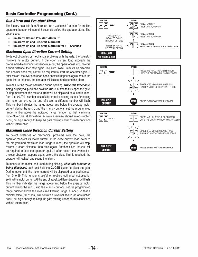
Run Alarm and Pre-start AlarmThe factory default is Run Alarm on and a 3-second Pre-start Alarm. The operator’s beeper will sound 3 seconds before the operator starts. The options are:
• Run Alarm Off and Pre-start Alarm Off• Run Alarm On and Pre-start Alarm Off• Run Alarm On and Pre-start Alarm On for 1-9 Seconds
Maximum Open Direction Current SettingTo detect obstacles or mechanical problems with the gate, the operator monitors its motor current. If the open current load exceeds the programmed maximum load range number, the operator will stop, reverse a short distance, then stop again. The Auto Close Timer will be disabled, and another open request will be required to start the operator again. If after restart, the overload or an open obstacle happens again before the open limit is reached, the operator will lockout and sound the alarm.
To measure the motor load used during opening, while this function is being displayed, push and hold the OPEN button to fully open the gate. During movement, the motor current will be displayed as a load number from 0 to 99. This number is useful for troubleshooting but not for setting the motor current. At the end of travel, a different number will fl ash. This number indicates the range above and below the average motor current during the run. Using the + and - buttons, set the programmed range number above the indicated range number, so that a minimal force (30-40 lbs. at 10-feet) will activate a reversal should an obstruction occur, but high enough to keep the gate moving under normal conditions without interruption.
Maximum Close Direction Current SettingTo detect obstacles or mechanical problems with the gate, the operator monitors its motor current. If the close current load exceeds the programmed maximum load range number, the operator will stop, reverse a short distance, then stop again. Another close request will be required to start the operator again. If after restart, the overload or a close obstacle happens again before the close limit is reached, the operator will lockout and sound the alarm.
To measure the motor load used during closing, while this function is being displayed, push and hold the CLOSE button to close the gate. During movement, the motor current will be displayed as a load number from 0 to 99. This number is useful for troubleshooting but not used for setting the motor current. At the end of travel, a different number will fl ash. This number indicates the range above and below the average motor current during the run. Using the + and - buttons, set the programmed range number above the measured fl ashing range number, so that a minimal force (50-75 lbs.) will activate a reversal should an obstruction occur, but high enough to keep the gate moving under normal conditions without interruption.
FUNCTION
SUGGESTED MINIMUM NUMBER WILLFLASH, ADJUST TO THE PROPER FORCE
OPTIONS
MAX CLOSECURRENT
PRESS AND HOLD THE CLOSE BUTTONUNTIL THE OPERATOR RUNS FULLY CLOSED
ENTER PRESS ENTER TO STORE THE FORCE
"CC"
FUNCTION
SUGGESTED MINIMUM NUMBER WILLFLASH, ADJUST TO THE PROPER FORCE
OPTIONS
MAX OPENCURRENT
PRESS AND HOLD THE OPEN BUTTONUNTIL THE OPERATOR RUNS FULLY OPEN
ENTER PRESS ENTER TO STORE THE FORCE
"OC"
FUNCTION
RUN ALARM ONPRE-START ALARM OFF
RUN ALARM ONPRE-START ALARM ON FOR 1 - 9 SECONDS
OPTIONS
RUN ALARMPRE-START ALARM
PRESS UP ORDOWN TO CYCLE
THROUGH OPTIONS
PRESS ENTER TOSELECT AN OPTION
RUN ALARM OFFPRE-START ALARM OFF"RP"

LRA Linear Residential Actuator Installation Guide - 15 - 228158 Revision X17 8-11-2011
Advanced Controller Programming
Entering Advanced Programming ModeTo access and program the Advanced Programming functions, for each programming session, Advanced Programming must be enabled.
After exiting programming, the Advanced Programming functions will be available on the programming display during the next programming session unless the operator has run 50 or more cycles. After that, Advanced Programming must be enabled again.
Maximum Run TimeThe factory default for the Maximum Run Time (MRT) is 99 seconds. When the operator starts, a timer will begin counting. If a open or close limit is not reached or an obstacle or reversing input is not received before the timer expires, the operator will stop, the unit locks out and the alarm sounds. The timer can be set for 10 to 99 seconds, but should be left at 99 in most applications. Setting it too close to the actual run time may cause the time to expire with changing ambient temperature, gate conditions, etc…
If AC is present and an open or close limit is not reached or an obstacle or reversing input is not received before this timer exceeds MRT, the operator will stop, the unit locks out and the alarm sounds.
In the case that AC is not present and MRT expires, it will be ignored as long as the actual run time is under 99 seconds. When the gate reached full open or full close position, MRT will be interpreted as fail safe/secure. EN05 will occur. If FS as set to fail safe, the gate will open. If FS is set to fail secure, the gate will close. However, if the actual run time is higher than 99, it will be interpreted as a physical mechanical problem, EN01 will occur and the gate will stop immediately.
Single Button Input SetupThis function is used for selecting the operation for single button controls and radio receivers.
The factory default sets the SINGLE input terminal so successive inputs will cycle the operator in OPEN-STOP-CLOSE-STOP order.
Alternately, the SINGLE input can be set to cause the gate to OPEN unless the gate is fully open. If the gate is fully open, the input will cause the gate to CLOSE.
FUNCTION
ADVANCED PROGRAMMING FUNCTIONSWILL NOT BE DISPLAYED
OPTIONS
PRESS UP ORDOWN TO CYCLE
THROUGH OPTIONS
PRESS ENTER TOSELECT AN OPTION
ADVANCEDPROGRAMMING
"AD"
ADVANCED PROGRAMMING OPTIONSWILL BE DISPLAYED
NOTE: ADVANCED PROGRAMMINGWILL STAY ENABLED AFTEREXITING PROGRAMMING UNTILTHE GATE CYCLES 50 TIMES
FUNCTION
SINGLE INPUT WILL OPEN OPERATOR,IF OPERATOR IS ALREADY OPEN, SINGLEINPUT WILL CLOSE OPERATOR
SINGLE INPUT WILL CYCLE OPERATORIN ORDER OF OPEN-STOP-CLOSE-STOP
OPTIONS
PRESS UP ORDOWN TO CYCLE
THROUGH OPTIONS
PRESS ENTER TOSELECT AN OPTION
SINGLE BUTTONINPUT SETUP
"SB"
FUNCTION
PRESS ENTER FOR 1 SECOND
WHILE DISPLAY IS FLASHING, PRESSUP OR DOWN TO CHANGE THEMAXIMUM RUN TIME (10-99 SECONDS)
OPTIONS
MAXIMUM RUNTIMER
DISPLAY SHOWS CURRENTMAXIMUM RUN TIME SETTING
ENTER
ENTER PRESS ENTER TO STORE THE VALUE
"RT"

LRA Linear Residential Actuator Installation Guide - 16 - 228158 Revision X17 8-11-2011
Advanced Controller Programming (Cont.)
Auxiliary Relay ModeThe Auxiliary Relay has normally open and normally closed contacts. The factory setting disables the Auxiliary Relay. The relay can be set for:
• Maglock: To deactivate a magnetic or solenoid gate lock, the relay will energize during any pending or actual gate motion (open only).
• M4: To deactivate a magnetic or solenoid gate lock, the relay will energize during any pending or actual gate motion (open only). 3 seconds after the gate starts to move, the relay will de-energize. This option is used for higher current solenoid locks.
• Ticket Dispenser: The relay will energize while the gate is moving in the open direction and at the full open limit, or in an entrapment condition.
• Strobe: To activate a warning strobe light, the relay will energize during any pending or actual gate motion (either open or close).
• Alarm: The relay will energize if the gate is manually forced open from the full closed position.
Reverse Delay TimeThe factory default sets the Reverse Delay to 1 second. The operator will wait the length of the delay before reversing direction. This feature will not change the reversal time when the operator is responding to an entrapment condition from an obstruction input or inherent entrapment protection sensor. The Reverse Delay can be set from 1 to 9 seconds. Heaver gates require a longer delay to allow time for the gate to stop.
Constant Pressure ModeThe factory default allows momentary pressure on a control station’s OPEN or CLOSE button to cycle the operator. The controller can be set to require constant pressure on the OPEN, CLOSE, or both buttons to run the operator.
✓ NOTE: If a button is set for constant pressure, and it is released before the operator reaches the open or close limit, the operator will stop the gate at its current position.
Shadow Loop Open PreventionIf the shadow loop is triggered, it always prevents the gate from closing if the Auto Close Timer activates or a CLOSE command is given while the gate is at the full open position.
The controller can also be set to prevent the gate from opening if the shadow loop is triggered while the gate is at the close limit position. This prevents a swing gate from opening into a vehicle if it’s parked near the gate on the inside.
FUNCTION
SET TIMER VALUE1 TO 9 SECONDS
OPTIONS
PRESS UP ORDOWN TO CYCLE
THROUGH OPTIONS
PRESS ENTER TOSELECT AN OPTION
REVERSEDELAY TIME
"RD"
FUNCTION
AUXILIARY RELAY USED FORMAGLOCK CONTROL
AUXILIARY RELAY DISABLED
AUXILIARY RELAY USED FORTICKET DISPENSER CONTROL
OPTIONS
PRESS UP ORDOWN TO CYCLE
THROUGH OPTIONS
PRESS ENTER TOSELECT AN OPTION
AUXILIARYRELAY MODE
"AR"
AUXILIARY RELAY USED FORWARNING STROBE LIGHT
AUXILIARY RELAY USED FORCONNECTION TO ALARM DEVICE
AUXILIARY RELAY USED FORMAGLOCK OR SOLENOID CONTROL3 SECOND DELAY TO RE-ENERGIZE
FUNCTION
CONSTANT PRESSURE SET TO OFF(MOMENTARY PRESSURE ON)
OPTIONS
PRESS UP ORDOWN TO CYCLE
THROUGH OPTIONS
PRESS ENTER TOSELECT AN OPTION
CONSTANTPRESSURE MODE
"CP"
OPEN BUTTON SET FORCONSTANT PRESSURE
CLOSE BUTTON SET FORCONSTANT PRESSURE
OPEN AND CLOSE BUTTONS BOTH SETFOR CONSTANT PRESSURE
FUNCTION
STANDARD OPERATIONSHADOW LOOP INHIBITS CLOSING ONLY
OPTIONS
PRESS UP ORDOWN TO CYCLE
THROUGH OPTIONS
PRESS ENTER TOSELECT AN OPTION
SHADOW LOOPOPEN PREVENTION
"SP"
OPEN INHIBIT ON, SHADOW LOOP INHIBITSOPENING AND CLOSING

LRA Linear Residential Actuator Installation Guide - 17 - 228158 Revision X17 8-11-2011
Advanced Controller Programming (Cont.)
Low Power ModeThis function is only used with DC battery backup. The factory default disables the Low Power Mode. When Low Power Mode is enabled, and AC power fails, the controller will assume Low Power Mode after 60 seconds of gate inactivity. Low power mode turns off all accessory power and indicators. Only inputs from the radio receiver, reverse loop, open loop (optional by programming), fi re department input, or restoring AC power will wake the Controller from Low Power Mode. Programming Mode can still be accessed while the Controller is awake in Low Power Mode.
Power Failure ModeThis function is only used with DC battery backup. The factory default is set for Fail Safe, alternately the Controller can be set for Fail Secure, Open Immediate, or Close Immediate.
• Fail Safe: If the AC power fails and the battery voltage drops below approximately 22 Volts, 5 seconds later the operator will cycle open if not already open. When AC power is restored, or the battery gets charged by solar panels, the operator will resume normal operation and auto-close if programmed to do so.
• Fail Secure: If the AC power fails and the battery voltage drops below approximately 22 Volts, 5 seconds later the operator will cycle closed if not already closed. When AC power is restored, or the battery gets charged by solar panels, the operator will resume normal operation.
• Open Immediate: If the AC power fails, the operator will cycle open if not already open and cease operation. When AC power is restored, the operator will resume normal operation and auto-close if programmed to do so.
• Close Immediate: If the AC power fails, the operator will cycle closed if not already closed and cease operation. When AC power is restored, the operator will resume normal operation.
Soft Start/Stop DurationThis function causes the operator to start and stop the DC motor slowly reducing gate wear and tear (at the full open or closed positions only). The factory default sets the Soft Start/Stop Duration to 3 seconds. The Soft Start/Stop Duration can be set from 1 to 10 seconds.
✓ NOTE: Changing the Soft Start/Stop Duration will reset the open and close current setting value to zero. It will be necessary to reprogram maximum open and close current settings.
Reset Cycle CountThe Controller counts of the number of times the operator has been cycled full open and close. The cycle count can be displayed. The display will scroll the cycle count number, fl ashing two digits at a time from left to right.
To reset the Cycle Count, press and hold the ENTER button for 2 seconds while the Cycle Count is displayed.
If the Maintenance Alert has been triggered, resetting the Cycle Count will also reset the Maintenance Alert indicator.
FUNCTION
SET TO FAIL SAFE MODE
OPTIONS
PRESS UP ORDOWN TO CYCLE
THROUGH OPTIONS
PRESS ENTER TOSELECT AN OPTION
POWERFAILURE MODE
"FS"
SET TO FAIL SECURE MODE
DC MODELSONLY
SET TO OPEN IMMEDIATE MODE
SET TO CLOSEIMMEDIATE MODE
FUNCTION
LOW POWER MODE DISABLED
OPTIONS
PRESS UP ORDOWN TO CYCLE
THROUGH OPTIONS
PRESS ENTER TOSELECT AN OPTION
LOW POWERMODE
"LP"
LOW POWER MODE #1RADIO WILL WAKE AND ACTIVATE,REVERSE LOOP WILL JUST WAKE
DC MODELSONLY
LOW POWER MODE #2 - RADIO OROPEN LOOP WILL WAKE AND ACTIVATE,REVERSE LOOP WILL JUST WAKE
THE FIRE DEPARTMENT INPUTWILL ALWAYS WAKE UP CONTROLLER
FUNCTION
SET SOFT START DURATION TIMEFROM 1 TO 10 SECONDS
SOFT START DISABLED
OPTIONS
PRESS UP ORDOWN TO CYCLE
THROUGH OPTIONS
PRESS ENTER TOSELECT AN OPTION
SOFT START/STOPDURATION
"SS"
DC MODELSONLY
FUNCTIONPRESS ENTER TO START THE CYCLE COUNT DISPLAY
1ST DISPLAY
NOTE: PRESS ENTER FOR 2 SECONDSWHILE THE "CT" FUNCTION IS DISPLAYEDTO RESET THE CYCLE COUNT TO ZERO
RESET CYCLECOUNT
"CT"
2ND DISPLAY 3RD DISPLAY 4TH DISPLAY
EXAMPLE ABOVE SHOWS 10,420 CYCLES
DECIMAL POINT LITON 4TH DISPLAY

LRA Linear Residential Actuator Installation Guide - 18 - 228158 Revision X17 8-11-2011
Advanced Controller Programming (Cont.)
Maintenance Alert TriggerThe Controller has a MAINT ALERT indicator that can be programmed to light when the number of activations exceeds a set number of cycles.
The factory default sets the Maintenance Alert Trigger to 10,000 cycles. The Maintenance Alert Trigger can be programmed for 5, 10, 15, or 25 thousand cycles.
The Maintenance Cycle Count can be reset independently from the operator’s absolute Cycle Count.
Mid-travel Stop PositionThe Controller can be programmed so the gate will stop at a mid-travel point instead of fully opening. This can be useful in installations where a large gate, that takes a long time to open and close fully, only needs to be opened partway to allow traffi c to pass.
The factory default sets the Controller for full open operation. Alternately, the Controller can be programmed to open for 1 to 99 seconds then stop, before reaching the open limit.
When a Mid-travel Stop Position time has been programmed, the gate will still fully open if the Fire Department input is triggered, if the OPEN button is held down beyond the Mid-travel Stop Position, or a close obstruction or reverse loop input is triggered.
Anti-tailgate EnableThe factory default sets the Anti-tailgate Enable to OFF. With this setting, during a gate cycle, after the shadow loop has been triggered by the vehicle and then has cleared after the vehicle passes, the Auto Close Timer or a CLOSE command is required to begin closing the gate.
If the Anti-tailgate Enable is set to ON, the gate will close immediately as soon as the shadow loop has cleared. Any subsequent shadow loop triggers while the gate is closing will stop the gate. When the shadow loop clears, the gate will continue closing.
Motor Type SelectionThe factory sets the default for the Controller to match the type of motor in the operator. When the Controller is used with the Model LRA Linear Residential Actuator leave this setting at the factory default.
FUNCTION
SETS THIS MAINTENANCE ALERT TRIGGERFOR 5, 10, 15, OR 25 THOUSAND CYCLES
DISABLES THE MAINTENANCE ALERTFUNCTION
RESETS THE MAINTENANCE ALERTINDICATOR AND SETS THE MAINTENANCEALERT COUNT TO ZERO
OPTIONS
PRESS UP ORDOWN TO CYCLE
THROUGH OPTIONS
PRESS ENTER TOSELECT AN OPTION
MAINTENANCEALERT TRIGGER
"MA"
FUNCTION
SET LENGTH OF OPENING TIMEFROM 1 TO 99 SECONDS
MID-TRAVEL STOP DISABLED(GATE RUNS FULL TRAVEL)
OPTIONS
PRESS UP ORDOWN TO CYCLE
THROUGH OPTIONS
PRESS ENTER TOSELECT AN OPTION
MID-TRAVELSTOP POSITION
"MT"
FUNCTION
MOTOR TYPESELECTION
"MO"
LEAVE THE CONTROLLER SET FORDC MOTOR OPERATION WITH
SOFT START/STOP FORALL MODEL LRA INSTALLATIONS
FUNCTION
ANTI-TAILGATE ENABLE OFFGATE REQUIRES AUTO OR MANUAL CLOSE
OPTIONS
PRESS UP ORDOWN TO CYCLE
THROUGH OPTIONS
PRESS ENTER TOSELECT AN OPTION
ANTI-TAILGATEENABLE
"AT"
ANTI-TAILGATE ENABLE ONGATE CLOSES WHEN SHADOW LOOP CLEARS
LRA Linear Residential Actuator Installation Guide - 19 - 228158 Revision X17 8-11-2011
Advanced Controller Programming (Cont.)
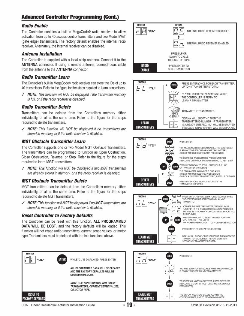
Radio EnableThe Controller contains a built-in MegaCode® radio receiver to allow activation from up to 40 access control transmitters and two Model MGT (gate edge) transmitters. The factory default enables the internal radio receiver. Alternately, the internal receiver can be disabled.
Antenna InstallationThe Controller is supplied with a local whip antenna. Connect it to the ANTENNA connector. If using a remote antenna, connect coax cable from the antenna to the ANTENNA connector.
Radio Transmitter LearnThe Controller’s built-in MegaCode® radio receiver can store the IDs of up to 40 transmitters. Refer to the fi gure for the steps required to learn transmitters.
✓ NOTE: This function will NOT be displayed if the transmitter memory is full, or if the radio receiver is disabled.
Radio Transmitter DeleteTransmitters can be deleted from the Controller’s memory either individually, or all at the same time. Refer to the fi gure for the steps required to delete transmitters.
✓ NOTE: This function will NOT be displayed if no transmitters are stored in memory, or if the radio receiver is disabled.
MGT Obstacle Transmitter LearnThe Controller supports one or two Model MGT Obstacle Transmitters. The transmitters can be programmed to function as Open Obstruction, Close Obstruction, Reverse, or Stop. Refer to the fi gure for the steps required to learn MGT transmitters.
✓ NOTE: This function will NOT be displayed if two MGT transmitters are already stored in memory, or if the radio receiver is disabled.
MGT Obstacle Transmitter DeleteMGT transmitters can be deleted from the Controller’s memory either individually, or all at the same time. Refer to the fi gure for the steps required to delete MGT transmitters.
✓ NOTE: This function will NOT be displayed if no MGT transmitters are stored in memory, or if the radio receiver is disabled.
Reset Controller to Factory DefaultsThe Controller can be reset with this function. ALL PROGRAMMED DATA WILL BE LOST, and the factory defaults will be loaded. This function will not erase radio transmitters, current sense values, or motor type. Transmitters must be deleted with the two functions above.
FUNCTION
TO DELETE ALL MGT TRANSMITTERS, PRESS ENTER FOR2 SECONDS, (TO EXIT WITHOUT DELETING ANY, QUICKLYPRESS ENTER)
ERASE MGTTRANSMITTERS
"MD" WILL BLINK FOR 30 SECONDS WHILE THE CONTROLLERIS READY TO DELETE ALL MGT TRANSMITTERS
"MD"ENTER PRESS ENTER
ENTER
THE DISPLAY WILL SHOW "DELETE ALL" AND THECONTROLLER RETURNS TO PROGRAMMING MODE
FUNCTION
INTERNAL RADIO RECEIVER DISABLED
OPTIONS
PRESS UP ORDOWN TO CYCLE
THROUGH OPTIONS
PRESS ENTER TOSELECT AN OPTION
RADIOENABLE
"RA"
INTERNAL RADIO RECEIVER ENABLED
FUNCTION
TO DELETE ALL TRANSMITTERS, PRESS ENTER FOR2 SECONDS, OR TO PICK TRANSMITTERS GO TO NEXT STEP
DELETETRANSMITTERS
"TD" WILL BLINK FOR 30 SECONDS WHILE THE CONTROLLERIS READY TO DELETE ONE OR MORE TRANSMITTERS,(TO EXIT WITHOUT DELETING ANY, PRESS ENTER)
"TD"ENTER PRESS ENTER
ENTER
ORUP DOWN
ENTER
PRESS UP OR DOWN TO SCROLL THROUGH THE LISTOF TRANSMITTER ID NUMBERS
THE TRANSMITTER ID NUMBER IS DISPLAYED(TO EXIT WITHOUT DELETING, PRESS ENTER)(TO PICK A DIFFERENT TRANSMITTER ID, PRESS UP OR DOWN)
PRESS ENTER FOR 2 SECONDS TO DELETE THETRANSMITTER DISPLAYED
FUNCTION
ACTIVATE THE MGT TRANSMITTER, THE DISPLAY WILLFLASH "rE" - IF THE TRANSMITTER IS ALREADY ENTERED,"DU" WILL BE DISPLAYED, IF DECODE IS BAD "ERROR" WILLBE DISPLAYED
LEARN MGTTRANSMITTERS
PRESS ENTER, "ML" WILL BLINK FOR 30 SECONDS WHILETHE CONTROLLER IS READY TO LEARN AN MGTTRANSMITTER"ML"
ENTER
ORUP DOWN
ENTER
DISPLAY WILL SHOW "--" FOR 5 SECONDS, THEN SHOW THETRANSMITTER'S ID NUMBER - REPEAT STEPS FORSECOND MGT TRANSMITTER IF USED
PRESS ENTER TO ACCEPT THE SELECTION
PRESS UP OR DOWN TO SELECT THE MGT FUNCTION:"rE" = REVERSE "St" = STOP "OP" = OPEN OBSTRUCTION "CL" = CLOSE OBSTRUCTION
FUNCTION
ACTIVATE THE TRANSMITTER
DISPLAY WILL SHOW "- -" THEN THETRANSMITTER ID NUMBER - IF TRANSMITTERIS ALREADY ENTERED, "dU" WILL BE DISPLAYED,IF DECODE IS BAD "ERROR" WILL BE DISPLAYED
LEARNTRANSMITTERS
"TL" WILL BLINK FOR 30 SECONDS WHILETHE CONTROLLER IS READY TOLEARN A TRANSMITTER
"TL"ENTER
PRESS ENTER (ONCE FOR EACH TRANSMITTER,UP TO 40 TRANSMITTERS TOTAL)
FUNCTION
RESET TOFACTORY DEFAULTS
"CL" ENTER WHILE "CL" IS DISPLAYED, PRESS ENTER
ALL PROGRAMMED DATA WILL BE CLEAREDAND THE FACTORY DEFAULTS WILL BESTORED IN MEMORY.
NOTE: THIS FUNCTION WILL NOT ERASETRANSMITTERS, CURRENT SENSE VALUES,OR MOTOR TYPE.
LRA Linear Residential Actuator Installation Guide - 20 - 228158 Revision X17 8-11-2011
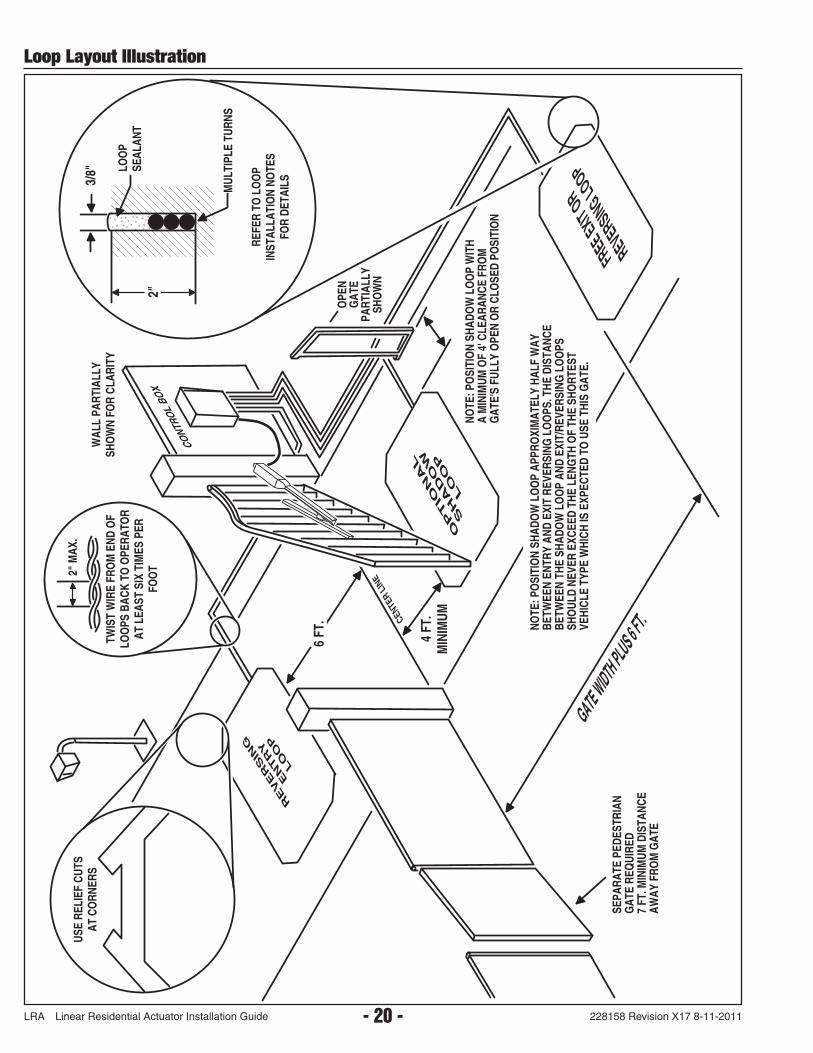
Loop Layout Illustration
2"
3/8"
4 FT
.M
INIM
UM
USE
RELI
EF C
UTS
AT C
ORN
ERS
TWIS
T W
IRE
FRO
M E
ND O
FLO
OPS
BAC
K TO
OPE
RATO
RAT
LEA
ST S
IX T
IMES
PER
FOO
T2" M
AX.
LOO
PSE
ALAN
T
MUL
TIPL
E TU
RNS
REFE
R TO
LO
OP
INST
ALLA
TIO
N NO
TES
FOR
DETA
ILS
OPE
NG
ATE
PART
IALL
YSH
OW
N
NOTE
: PO
SITI
ON
SHAD
OW
LO
OP
APPR
OXI
MAT
ELY
HALF
WAY
BETW
EEN
ENTR
Y AN
D EX
IT R
EVER
SING
LO
OPS
. THE
DIS
TANC
EBE
TWEE
N TH
E SH
ADO
W L
OO
P AN
D EX
IT/R
EVER
SING
LO
OPS
SHO
ULD
NEVE
R EX
CEED
THE
LEN
GTH
OF
THE
SHO
RTES
TVE
HICL
E TY
PE W
HICH
IS E
XPEC
TED
TO U
SE T
HIS
GAT
E.
WAL
L PA
RTIA
LLY
SHO
WN
FOR
CLAR
ITY
SEPA
RATE
PED
ESTR
IAN
GAT
E RE
QUI
RED
7 FT
. MIN
IMUM
DIS
TANC
EAW
AY F
ROM
GAT
E
6 FT
.
NOTE
: PO
SITI
ON
SHAD
OW
LO
OP
WIT
H A
MIN
IMUM
OF
4' C
LEAR
ANCE
FRO
MG
ATE'
S FU
LLY
OPE
N O
R CL
OSE
D PO
SITI
ON

LRA Linear Residential Actuator Installation Guide - 21 - 228158 Revision X17 8-11-2011
Safety Edge Layout Illustration
RECE
IVER
FO
R G
ATE
EDG
E TR
ANSM
ITTE
RBU
ILT
INTO
CO
NTRO
LLER
GAT
E ED
GE
TRAN
SMIT
TER
#1
SEPA
RATE
PED
ESTR
IAN
GAT
E RE
QUI
RED
7FT.
MIN
IMUM
DIS
TANC
EAW
AY F
ROM
GAT
E
EDG
E M
OUN
TED
ON
LEAD
ING
OUT
SIDE
EDG
EO
F G
ATE
EDG
ES M
OUN
TED
ACRO
SSBO
TTO
M O
F G
ATE
WIR
E ED
GES
SHO
WN
TO T
HE C
LOSE
OBS
TRUC
TIO
N IN
PUT
ONL
YO
R TO
WIR
ELES
S G
ATE
EDG
E TR
ANSM
ITTE
RS
ITEM
DES
CRIP
TIO
N
1
GAT
E (R
EFER
ENCE
ONL
Y)
2
EDG
E
3
EDG
E EX
TRUS
ION
4
S
PACE
RS (3
)
5
8-3
2 X
1" S
CREW
S (3
)
6
RET
AINI
NG B
RACK
ET
REVE
RSIN
G E
DGE
ASSE
MBL
Y CL
OSE
-UP
5
1
2
34
6
GAT
E ED
GE
TRAN
SMIT
TER
#2
WAR
NING
On
e or
mor
e co
ntac
t se
nsor
s sh
all b
e lo
cate
d on
the
in
side
and
out
side
lea
ding
edg
e of
a s
win
g ga
te.
Addi
tiona
lly,
if th
e bo
ttom
edg
e of
a s
win
g ga
te i
s gr
eate
r th
an s
ix i
nche
s (1
52 m
m)
abov
e th
e gr
ound
at
any
poi
nt in
its
arc
of t
rave
l, on
e or
mor
e co
ntac
t se
nsor
s sh
all b
e lo
cate
d on
the
bott
om e
dge.
A ha
rdw
ired
cont
act
sens
or s
hall
be l
ocat
ed a
nd i
ts
wiri
ng a
rran
ged
so t
hat
the
com
mun
icat
ion
betw
een
the
sens
or a
nd t
he g
ate
oper
ator
is n
ot s
ubje
cted
to
mec
hani
cal d
amag
e.A
wire
less
con
tact
sen
sor
such
as
one
that
tra
nsm
its
radi
o fr
eque
ncy
(RF)
sig
nals
to
the
gate
ope
rato
r fo
r en
trap
men
t pro
tect
ion
func
tions
shal
l be
loca
ted
whe
re
the
tran
smis
sion
of
the
sign
als
are
not
obst
ruct
ed o
r im
pede
d by
bui
ldin
g st
ruct
ures
, na
tura
l la
ndsc
apin
g or
sim
ilar o
bstr
uctio
n. A
wire
less
con
tact
sen
sor s
hall
func
tion
unde
r the
inte
nded
end
-use
con
ditio
ns.

LRA Linear Residential Actuator Installation Guide - 22 - 228158 Revision X17 8-11-2011
Photoeye Installation Illustration
SEPA
RATE
PED
ESTR
IAN
GAT
E RE
QUI
RED
7 FT
. MIN
IMUM
DIS
TANC
E AW
AY F
ROM
GAT
E
OBS
TRUC
TIO
N DE
TECT
ING
APP
LICA
TIO
N
(WIR
E TO
CLO
SE O
BSTR
UCTI
ON)
OBS
TRUC
TIO
N DE
TECT
ING
APP
LICA
TIO
N
(WIR
E TO
OPE
N O
BSTR
UCTI
ON)
PHO
TOEY
E RE
VERS
E AP
PLIC
ATIO
N
(WIR
E TO
REV
ERSE
)
BEAM
PAT
H
BEAM
PAT
H
BEAM
PAT
H
THIS
DRA
WIN
G IS
INTE
NDED
TO
DRA
W A
TTEN
TIO
N TO
PO
SSIB
LE L
OCA
TIO
NS F
OR
THE
INST
ALLA
TIO
NO
F CO
NTAC
T O
R NO
N-CO
NTAC
T O
BSTR
UCTI
ON
SENS
ING
DEV
ICES
. OTH
ER A
REAS
OF
ENTR
APM
ENT
MAY
EXI
ST D
EPEN
DING
ON
EACH
SPE
CIFI
C IN
STAL
LATI
ON.
CARE
MUS
T BE
TAK
EN T
O P
OSI
TIO
N PH
OTO
EYES
SO
THA
T NU
ISAN
CE T
RIPP
ING
IS M
INIM
IZED
.
REFE
R TO
CO
NNEC
TIO
N IL
LUST
RATI
ONS
FO
R DE
TAIL
S
LRA Linear Residential Actuator Installation Guide - 23 - 228158 Revision X17 8-11-2011
Gate Operation
Open ButtonOpens the gate. If the Controller is programmed to stop opening the gate at mid-travel, a constant press of the OPEN button will override the Mid-travel Stop and completely open the gate. If the Auto Close Timer is set, it will be suspended until the OPEN button is released.
Close ButtonCloses the gate if the gate is open. Also closes the gate if the gate is in the process of opening.
Stop ButtonStops the gate from opening or closing at any time.
Single InputOpens the gate if it’s closed and closes the gate if it’s open (open-close programming option). Activating the input while the gate is moving will reverse the gate.
Can be programmed to stop the gate while the gate is moving (open-stop-close programming option).
Fire Department InputFully opens the gate when the input is activated. Overrides the Mid-travel Stop and Auto Close Timer (if either is programmed for the gate). The gate will lockout in the open position without sounding the alarm. Press the STOP button to release the lockout.
Open InputFunctions the same as the OPEN button.
Open ObstructionWhile the gate opening, any open obstruction signal will cause the gate to stop, reverse a short distance, and then stop again. The Auto Close Timer will be disabled, and a renewed input will be required to start the gate again. Should the gate be restarted and the obstacle signal occur again prior to reaching a limit, the gate will stop again, lockout, and sound the emergency alarm.
Close ObstructionSame as the open obstruction, but in the closing direction.
Reverse InputIf the reverse input is triggered while the gate is closing, the gate will reverse to the full open position. If the Auto Close Timer is set, when the reverse input is cleared, the gate will close when the Auto Close Timer expires.
Open LoopFunctions the same as the OPEN button.
Reverse LoopFunctions the same as the reverse input.
Shadow/Reset LoopHolds the gate fully open or fully closed while triggered. If open, the gate closes immediately when cleared if Anti-tailgate is enabled.
Operation IndicationsDuring normal operation, the Controller’s displays will indicate current operating conditions and status.
Power-up DisplayWhen the Controller powers up, dashes will show on the display, then the fi rmware version number, then the gate type (SL for slide and swing gates).
Exiting programming restarts the Controller. The power-up display will show upon the restart.
Idle ConditionWhile the Controller is idling, waiting for a command, the display will show circulating dashes.
For DC models only - Clockwise : Batteries discharging, Counterclockwise : Batteries charging
Last Gate Position/ConditionWhen the gate moves or stops, the display will show the status for up to one minute.
• Stop is displayed as St• Full Close is displayed as FC• Full Open is displayed as FO• Entrapment is displayed as En
Pre-start DelayDuring the pre-start delay, the display will countdown the number of seconds remaining before the operator starts.
Reverse DelayIf the gate travel direction is reversed from a user activation or reversing device, and a reverse delay is set, the display will count down the delay time in seconds before the operator restarts.
Run TimerWhile the gate is opening or closing, the number of seconds running time is displayed.

LRA Linear Residential Actuator Installation Guide - 24 - 228158 Revision X17 8-11-2011
Error IndicationsDuring abnormal operation, the Controller’s displays and beeper will indicate the error condition that has occurred.
EntrapmentIf an entrapment condition occurs detected by two repeated open or close obstruction triggers, the Controller will lock the operator out. The beeper will sound constantly and the gate will not operate. To reset the Controller press the STOP button or press the RESET button on the control box.
MGT Obstacle Transmitter TroubleIf any MGT transmitters are used with the operator, their supervision feature will alert the Controller if there is any trouble with the transmitter. MGT transmitters send hourly status reports and will send low battery reports when the transmitter has a low battery. The MGT transmitters also have a tamper detection switch that will trigger when their case is opened.
When the Controller detects a low transmitter battery, a tamper signal, or missing transmitter status reports, the gate will still operate normally, but the beeper will change as follows:
• The Pre-start Alarm will beep twice as fast.• The Run Alarm will beep twice as fast and continue for fi ve minutes
after the gate stops.• The sounder will “chirp” every fi ve seconds when the gate is idle.
Correct the trouble (close case, replace battery, or replace transmitter) to clear the obstacle transmitter trouble indications.
Maximum Run Time ExceededIf the Maximum Run Time is exceeded, the Controller stops the operator the same as if a double obstacle has occurred in an entrapment condition. The entrapment alarm sounds constantly, and is cleared by pressing the STOP button or the RESET button on the cover. After the STOP or RESET button is pressed, because the Maximum Run Time has been exceeded, the sounder will beep twice every fi ve seconds. The next operation of the gate will clear the indication.
CONTROLLER ERROR CAUSES AND INDICATIONS
ERROR CAUSE ERROR INDICATION HOW TO CLEAR
TWO SAFETY REVERSALS (ON SINGLE GATE OR ON EITHER DUAL GATE)
En 00, CONTINUOUS ALARM BEEPER, GATE DISABLED
PRESS STOP BUTTON
MAXIMUM RUN TIMER EXCEEDED ON OPENING
En 01, AND MAX RUN LED, CONTINUOUS ALARM BEEPER, GATE DISABLED
PRESS STOP BUTTON, CLEARS CONTINUOUS ALARM, THEN DOUBLE BEEP EVERY 5 SECONDS UNTIL NEXT OPERATION
MAXIMUM RUN TIMER EXCEEDED ON CLOSING
En 02, AND MAX RUN LED, CONTINUOUS ALARM BEEPER, GATE DISABLED
PRESS STOP BUTTON, CLEARS CONTINUOUS ALARM, THEN DOUBLE BEEP EVERY 5 SECONDS UNTIL NEXT OPERATION
COMM LINK FAILURE
En 03, AND COMM LINK LED, CONTINUOUS ALARM BEEPER FOR 1 MINUTE, GATE DISABLED (EXCEPT FOR FIRE DEPT INPUT)
COMM LINK NOT USED IN LRA DUAL GATE INSTALLATIONS. BE SURE APEX IS SET FOR SINGLE GATE.
GATE FULL OPEN RESULTING FROM FIRE DEPT INPUT
En 04, GATE DISABLED PRESS STOP BUTTON
FAIL SAFE OR FAIL SECURE BECAUSE OF BATTERY VOLTAGE DROP BELOW 21.6 VDC DUE TO AC POWER LOSS
En 05, GATE DISABLEDBATTERY VOLTAGE MUST RISE ABOVE 24 VDC
OTHER CONTROLLER IN ENTRAPMENT (DUAL GATE)
En 06, GATE DISABLED
CLEAR ENTRAPMENT ON OTHER CONTROLLER (PRESS STOP)
LOW AC VOLTAGE AT CONTROLLER
En 07, GATE DISABLEDRESTORE AC POWER TO NORMAL LEVEL
INPUT TRIGGERED DURING ENTRAPMENT LOCKOUT
En 08, GATE DISABLED PRESS STOP BUTTON
COMPATIBILITY PROBLEM
En 09, GATE DISABLEDUPDATE FIRMWARE AND RESET BOTH PAIRED CONTROLLERS
EEPROM PROBLEM En 10, GATE DISABLEDTRY RESET, CALL TECH. SUPPORT
DC MOTOR MISMATCH En 11, GATE DISABLED
REPROGRAM MOTOR TYPE OR CHANGE DC MOTOR BOARD, NEXT GATE MOVEMENT WILL RETRY DC MOTOR CHECK
MOTOR FAILURE En 12, GATE DISABLED REPLACE MOTORAC POWER LOSS IN OPEN OR CLOSE IMMEDIATE POWER FAIL MODE
En 13 REAPPLY AC POWER
MAXIMUM RUN TIMER EXCEEDED AFTER AC POWER LOSS
En 14
BATTERY VOLTAGE MUST RISE ABOVE 24 VOLTS
MGT SUPERVISORY CONDITION (TAMPER, LOW BATTERY, MISSING HOURLY STATUS)
FAST BEEPS DURING PRESTART, FAST BEEP RUN ALARM, CHIRP EVERY 5 SECONDS AT IDLE
CLEARS WHEN MGT CONDITION CLEARS
WARNING The Stop and/or Reset button must be located in the line-of-sight of the gate. Activation of the reset control shall not cause the operator to start.
LRA Linear Residential Actuator Installation Guide - 25 - 228158 Revision X17 8-11-2011
Troubleshooting
Contacting Technical SupportFor technical questions regarding Linear gate operators, contact the Technical Services Department at:
1-800-421-1587 from 6:30 AM to 4:30 PM Pacifi c time
Operator fails to startA. Make sure you have power at the master distribution
panel and that the power has not been turned off.
B. If the “Reset to Factory Defaults” (CL) programming step has been used, ensure the motor type (MO) has been set to d2 and open (OC) and closed currents (CC) have been set.
Motor operates, but gate does not moveA. Make sure all mounting hardware is still attached and
that all fasteners are tight.
B. Check that the actuator worm gear is moving. If it isn’t, the gears in the drive may have stripped.
Motor sounds like it is working harder than normalA. Make sure the gate is moving freely and without binding
throughout its entire travel.
Gate stopping part way open or closed (but no visible obstruction)A. The Controller may have received a false obstruction
input triggered by current sensing set too low. Make sure the gate moves freely through its entire travel before adjusting the current sensing.
B. The Maximum Run Timer may have counted down and expired. This can be caused by having the timer set too low. When the timer expires, the gate stops and the beeper will sound.
C. An obstruction signal from an accessory wired to the obstruction input may have triggered falsely. Check the control board for lit indicators for any of the following inputs: safety, shadow/reset, open obstruction, close obstruction, stop, etc. If any are lit when the operator should be running, remove all devices hooked to that function and hook them up one at a time and try to run the operator until the problem device is found. Refer to Page 8 for details on the control board indicators.
Gate staying open with automatic systemA. If there are vehicle detectors used with the operator, one
of the loops or loop detectors may be sending a false signal or needs to be reset. Observe the indicators on the loop detector. Unplug the detector and try running the operator.
B. An opening or reversing device may be stuck or malfunctioning. Try disconnecting these devices and hook them back up one at a time and try running the operator until the malfunctioning device is found.
How to Order Replacement PartsUse the part numbers listed on the following pages.
Contact your local Linear dealer or distributor to order parts.1. Supply the model number and serial number of your operator.2. Specify the quantity of pieces needed and order by part number and name of part.3. State whether to ship by freight, truck, parcel post, UPS or air express.4. State whether transportation charges are to be prepaid or collect.5. Specify name and address of person or company to whom parts are to be shipped.6. Specify name and address of person or company to whom invoice is to be sent

LRA Linear Residential Actuator Installation Guide - 26 - 228158 Revision X17 8-11-2011
Model LRA Replacement Parts
HARDWARE KIT
POSTBRACKETKIT GATE BRACKET KIT
WORM DRIVE CAP,TRAVELER, & GATE
BRACKET KITKIT #3 90
30
1
2
28
91
KIT #4
63
17
101
27
65
44
KIT #1
KIT #2
101
17
2664
99
17
101
99
92
9495
9625
97
2500-2436LRA COMPLETE ARM
31
32
33
MODEL LRA ARM MECHANICAL PARTS LISTREF. # PART # ITEM # REPLACEMENT PART QTY.
KIT #1Gate Bracket Kit
2500-2470
99 Gate Bracket 164 Magnet Holder 117 Seeger Ring D25 1
101 Spacer 126 Limit Magnet 2
KIT #2Traveler, Cap, & Gate Bracket Kit
2500-2479
99 Gate Bracket 196 Arm Cap 194 Traveler 197 Self-tapping Screw 4x18 225 Self-tapping Screw 5x20 317 Seeger Ring D25 1
101 Spacer 195 Self-lubricating Bushing 192 Traveler Shell 2
KIT #3Post Bracket Kit
2500-2469
91 Locknut 128 Washer 230 Bushing 3090 Seeger Ring D12 12 Operator Bracket 11 Operator Bracket Pin 131 Bolt 332 Locknut 333 Post Bracket 1
KIT #4Hardware Kit
2500-2478
65 Wiring Cover 144 Self-Tapping Screw 317 Seeger Ring D25 1
101 Spacer 127 O-ring 163 Release Key 1
KIT #5Limit Switch Kit
2510-461
29 Reed Sensor 166 Sensor Cover 121 Wire Holder 27 Self-Tapping Screw 1
63 2500-2471 Release Key Only 12500-2436 Complete LRA Arm (w/o Controller) 1
MODEL LRA CONTROLLER MECHANICAL PARTS LISTREF. # PART # DESCRIPTION
2500-2474 Arm-to-Controller Cable, By Foot2100-2119 Apex LRA Mounting Plate2500-2472 Controller Enclosure (Complete w/o Apex Module)2500-2476 24 Volt Plug-in Transformer2520-518 Controller (Complete)
2500-2511 Apex Dual Capable DC Motor Module
LRA2 DUAL GATE KITREF. # PART # DESCRIPTION
LRA2Second LRA arm kit for dual-gate installations(kit includes one LRA arm, 40-feet of cable, and wiring strain-relief bushing)

LRA Linear Residential Actuator Installation Guide - 27 - 228158 Revision X17 8-11-2011
Preventative Maintenance
GeneralLinear gate operators are designed for many years of trouble-free operation and, under recommended operating conditions, will require only minimal maintenance. To ensure that a unit is ready for operation at all times, and to preclude serious damage or failure, inspect the unit systematically. Proper adjustments and lubrication should be made as recommended.
Lubrication✓ Motor — Motors have sealed ball bearings and do not
require further lubrication.
✓ Post Bracket Pin & Traveler Shaft — Lubricate the front and back pivot points with a lithium complex-based grease.
✓ Actuator Body — Wipe down the unit with a clean rag.
✓ Control Cable — Inspect the operator to control box cable for cracks in the insulation, breaks, or other signs of failure. Check all connection points. Replace cable if necessary.
6-Month Preventative Maintenance1. Inspect all nuts and bolts for proper tightness and tighten
as necessary.
2. Check all reversing devices for proper function. Inspect all contact edges for wear and replace if required. Check photoeyes for proper alignment and function.
3. Check current sensing for proper adjustment when fi nished with inspection and maintenance.
4. Inspect the installation area. Are all the warning signs intact and visible? If they are missing or need replaced, contact Linear. Be sure there are no control stations mounted within reach of the gate. Review safety literature with the customer and advise them to remove any such stations found.
Battery MaintenanceThe gel-cell batteries in this operator require no routine maintenance. For assured continued performance, they should be replaced every year. If power is to be removed for one week or more, disconnect the negative wire from the batteries as this will prevent deep discharging. Fully charge before use after storage or upon initial installation.
FCC NoticeThis device complies with FCC Rules Part 15 and Industry Canada Rules & Regulations. Operation is subject to the following two conditions: (1) This device may not cause harmful interference and (2) this device must accept any interference received, including interference that may cause undesired operation.
For all gate operators, you must inspect the gate for proper operation. The gate should move easily without binding through its entire travel. If the gate does bind, adjust or fi x as required. Failure to keep the gate in good working condition will have adverse effects on the operator.
WARNING Always disconnect power from operator before servicing. Keep clear of gate during operation.

LRA Linear Residential Actuator Installation Guide - 28 - 228158 Revision X17 8-11-2011
Gate Operator Installation Checklist
❑ ❑ 1. The gate has been checked to make sure it is level and moves freely in both directions.
❑ ❑ 2. Potential pinch areas have been guarded so as to be inaccessible OR have contact and/or non-contact obstruction sensing devices installed.
❑ ❑ 3. The installer has installed one or more contact or non-contact obstruction sensing devices, in compliance with UL325 requirements for this installation.
❑ ❑ 4. If pedestrian traffi c is expected, a separate pedestrian gate has been installed, a minimum of seven feet from the gate. The customer has been informed that all pedestrian traffi c must use the pedestrian gate.
❑ ❑ 5. Warning signs have been installed on each side of the gate in highly visible locations. The customer has been informed that these signs must remain at all times.
❑ ❑ 6. There are no controls installed on the gate operator, or within seven feet of the gate.
❑ ❑ 7. The installer has properly adjusted the obstruction sensing feature and has tested the gate to make sure that the gate stops and reverses a short distance with minimal resistance applied (40 lbs. on a swing gate at the end of the gate, 75 lbs. on a slide gate)
❑ ❑ 8. The installer has instructed the customer in the proper use of the gate operator and reviewed all of the operational functions, obstruction sensing devices, warning beeper and reset, etc.
❑ ❑ 9. The installer has instructed the customer in the proper use of the operator’s manual disconnect feature. The manual disconnect must never be used while the gate is in motion. The power switch must be turned off before using the manual disconnect and disengaging the operator.
❑ ❑ 10. The installer has reviewed all safety instructions with the customer, and has left the safety instructions and owner’s information sheets for their reference.
❑ ❑ 11. The installer has answered any questions the customer has regarding the operation of the gate operator and gate operator safety precautions.
❑ ❑ 12. The installer has explained to the customer that a regular maintenance schedule for both the gate and the gate operator is recommended.
By signing this installation checklist, I/we hereby certify that each item listed and checked above has been covered by the installer and is clearly understood by the customer.
INSTALLER CUSTOMER
Customer’s Signature
Installer’s Signature
Date
Date