Linear Optics Corrections
20
Linear Optics Corrections RHIC: Todd Satogata, Mei Bai, Jen Niedziela AGS: Vincent Schoefer, Kevin Brown, Leif Ahrens, … November 3, 2006 Objective Reduce machine/model difference in optics, in both directions! Orbit Response Matrix AC Dipole Optics AGS Orbit Response Matrix
-
Upload
lucas-marsh -
Category
Documents
-
view
39 -
download
0
description
Linear Optics Corrections. RHIC: Todd Satogata, Mei Bai, Jen Niedziela AGS: Vincent Schoefer, Kevin Brown, Leif Ahrens, … November 3, 2006. Objective Reduce machine/model difference in optics, in both directions! Orbit Response Matrix AC Dipole Optics AGS Orbit Response Matrix. - PowerPoint PPT Presentation
Transcript of Linear Optics Corrections

Linear Optics CorrectionsLinear Optics Corrections
RHIC: Todd Satogata, Mei Bai, Jen NiedzielaAGS: Vincent Schoefer, Kevin Brown, Leif Ahrens, …
November 3, 2006
ObjectiveReduce machine/model difference in optics, in both directions!
Orbit Response Matrix AC Dipole Optics AGS Orbit Response Matrix
November 3, 2006
T. Satogata - APEX Linear Optics 2
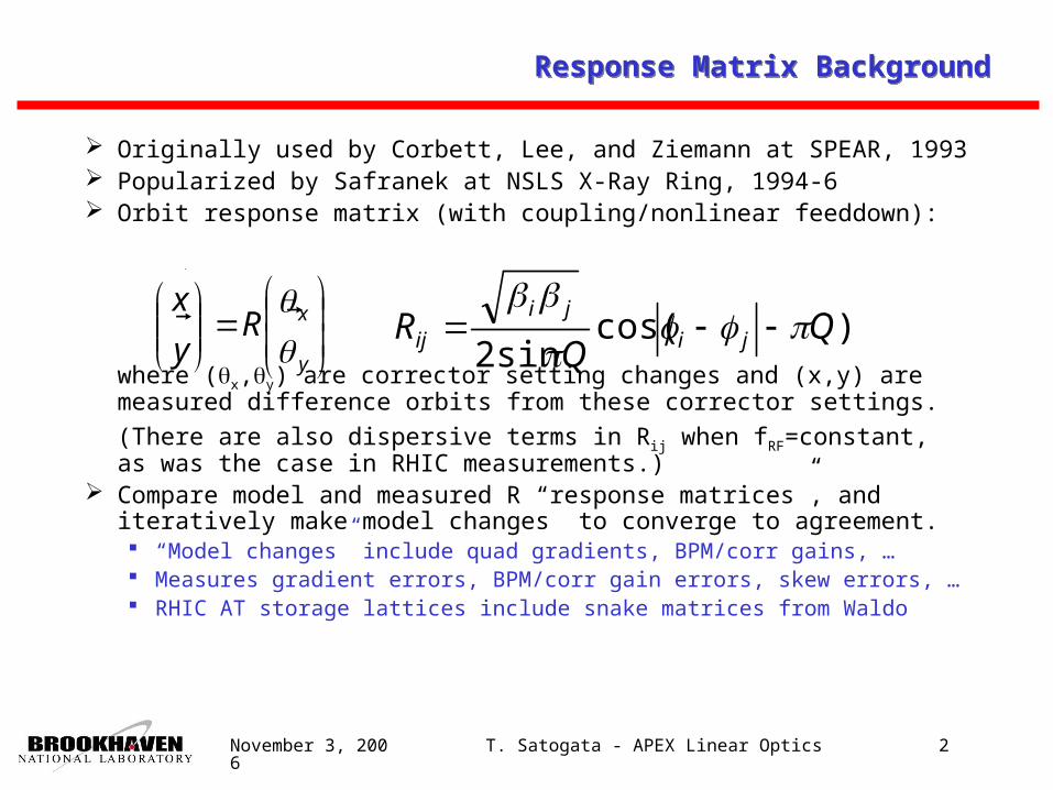
Response Matrix BackgroundResponse Matrix Background
Originally used by Corbett, Lee, and Ziemann at SPEAR, 1993
Popularized by Safranek at NSLS X-Ray Ring, 1994-6 Orbit response matrix (with coupling/nonlinear feeddown):
where (x,y) are corrector setting changes and (x,y) are measured difference orbits from these corrector settings.(There are also dispersive terms in Rij when fRF=constant, as was the case in RHIC measurements.)
Compare model and measured R “response matrices”, and iteratively make model changes to converge to agreement. “Model changes” include quad gradients, BPM/corr gains, … Measures gradient errors, BPM/corr gain errors, skew errors, … RHIC AT storage lattices include snake matrices from Waldo
y
xRy
x
)cos(sin2
R ji
ji
ij

November 3, 2006
T. Satogata - APEX Linear Optics 3
Response Matrix BackgroundResponse Matrix Background
The difference between Rmodel and Rmeasured is written as a single vector with length (NbpmsxNcorrs), and expanded in terms of variable changes vk, that include quad gradient errors, corrector and BPM gain errors, skew errors, etc:
This can be solved for vk with SVD, assuming a good model for . The quadrupole gradient error dependence is nonlinear, so the SVD solution is iterated through the model until it converges. Weight with BPM noise I
N
N
Nnmnmnm
Nmnmnmn
N
N
nm
mn
v
v
v
v
vRvRvR
vRvRvR
vRvRvR
vRvRvR
R
R
R
R
1
2
1
21
)1(2)1(1)1(
12212112
11211111
)1(
12
11
...
/...//
/...//
............
/...//
/...//
...
kij vR /

November 3, 2006
T. Satogata - APEX Linear Optics 4
Simulation Results: No BPM NoiseSimulation Results: No BPM Noise
Tested yellow store lattice, random –0.1 to 0.1% quad errs With no BPM noise, fitting is “perfect”
Lattice is therefore nondegenerate

November 3, 2006
T. Satogata - APEX Linear Optics 5
Issue: BPM Noise from 10 HzIssue: BPM Noise from 10 Hz
Average orbit noise at store: 30-40 um horizontal peak-peak 7800 turn averaging gives 15-20 um peak-peak Need ~10 orbits per data point to achieve 5 um BPM noise,
including BPM change to average orbit sampling period

November 3, 2006
T. Satogata - APEX Linear Optics 6
20% beta beat before fit
0.2% beta beat after fit
Simulation Results: 30 um BPM NoiseSimulation Results: 30 um BPM Noise
With 30 um BPM noise, error bars are larger than errors Fits are inexact, but method still converges – not unique Beta beating is reduced by two orders of magnitude
November 3, 2006
T. Satogata - APEX Linear Optics 7
Before After
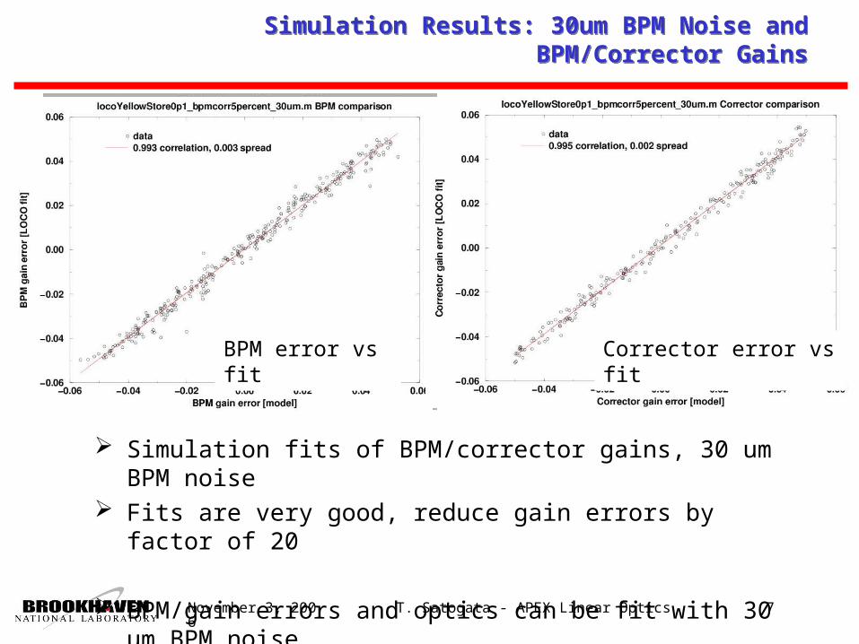
Simulation Results: 30um BPM Noise and BPM/Corrector Gains
Simulation Results: 30um BPM Noise and BPM/Corrector Gains
Simulation fits of BPM/corrector gains, 30 um BPM noise Fits are very good, reduce gain errors by factor of 20
BPM/gain errors and optics can be fit with 30 um BPM noise
BPM error vs fit Corrector error vs fit

November 3, 2006
T. Satogata - APEX Linear Optics 8
APEX Data Acquisition and ORM Data Summary (pp35)APEX Data Acquisition and ORM Data Summary (pp35)
Data acquisition and analysis: Takes 1-2 hours for all correctors in either RHIC ring Both rings done in parallel for storage measurement 3 average orbits acquired for each corrector setting Need to automate analysis, tedious BPM/corrector
alignment and orbit averaging Measure/monitor tunes throughout measurement
No good blue injection ORM data acquired during Run-6 Yellow injection data taken during blue polarimeter
pumpdown
Machine State
Date BPMs Correctors
Yellow injection
May 10 2006 159+161 117+117
Yellow store May 30 2006 89+90 113+116
Blue store May 30 2006 147+145 112+112

November 3, 2006
T. Satogata - APEX Linear Optics 9
30-50% “signal”, chi^2=54
ORM reduces difference, chi^2 by >10
Beam Experiment Analysis: pp35 Yellow Store Q1/8/9Beam Experiment Analysis: pp35 Yellow Store Q1/8/9
Use only arc BPMs, fit Q1/Q8/Q9 quadrupoles Appears to converge, chi^2 reduces by factor 10 Beta beating is 10-15% horizontal, over 40% vertical! Fitted quadrupole errors are still too large by at least x10
Example: yi6-qf8 fit converges to a change of –5% ! Check data

November 3, 2006
T. Satogata - APEX Linear Optics 10
ORM reduces difference, chi^2 by 20
Beam Experiment Analysis: pp35 Yellow Store Q1/4-9Beam Experiment Analysis: pp35 Yellow Store Q1/4-9
Use only arc BPMs, but now fit Q1/4-9 quadrupoles Appears to converge better, chi^2 reduces by factor 20 Beta beating is consistent with previous result, smoother Fitted quadrupole errors are even larger, up to 8%!
Need to double-check data; these errors are unphysical
November 3, 2006
T. Satogata - APEX Linear Optics 11
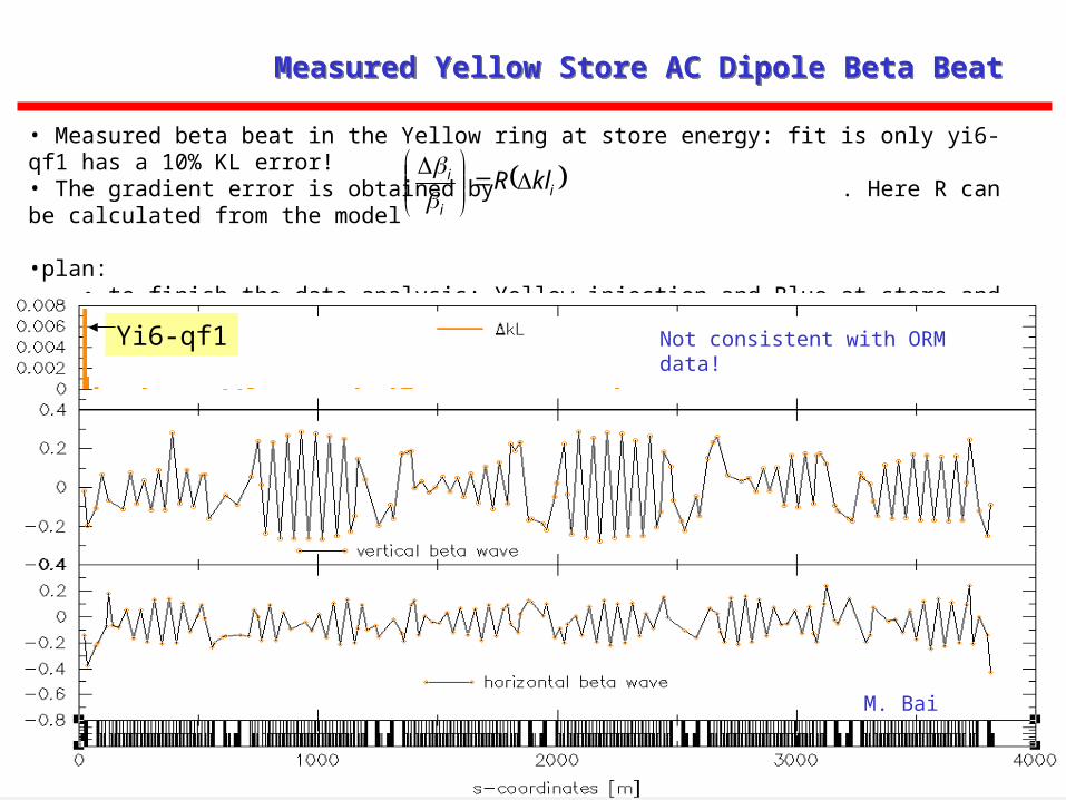
• Measured beta beat in the Yellow ring at store energy: fit is only yi6-qf1 has a 10% KL error!• The gradient error is obtained by . Here R can be calculated from the model
•plan:• to finish the data analysis: Yellow injection and Blue at store and injection• dedicated gradient error measurement at injection
Yi6-qf1
ii
i klR
Measured Yellow Store AC Dipole Beta BeatMeasured Yellow Store AC Dipole Beta Beat
M. Bai
Not consistent with ORM data!

November 3, 2006
T. Satogata - APEX Linear Optics 12
Future PlansFuture Plans
Careful analysis of existing data Remove suspicious data, hand-match full ORM matrices Aggressive singular value cuts; existing too permissive?
Blind baseline APEX Insert and measure known quadrupole errors
Improve BPMs, reduce data acquisition noise Change BPM average orbit sampling time Increase number of orbits acquired per corrector setting
Reduce dimensionality Typically 20-25% of correctors are used (FNAL, ALS) Speeds up data acquisition, analysis, reduces memory
requirements Coupling analysis
Reduced dimensionality should allow this

November 3, 2006
T. Satogata - APEX Linear Optics 13
APEX Requests and RequirementsAPEX Requests and Requirements
2-3h Blue testing at injection during startup period Decouple; separate/measure tunes for lattice fit; save model Measure dispersion before and after ORM measurement BPMs averaging set to 7800 turns to limit 10 Hz (nth turn?) Measure BPM average orbit noise at all BPMs Compare difference orbit measurement/prediction, dispersion Measure ORM/correct optics/recheck if differences above
noise AC dipole and ORM optics measurements Fit all quads to improve model, IR knobs to improve machine (Fast) blind baseline measurement for AC dipole analysis Remeasure after analysis and correction for validation
3h Storage optics measurement/correction Repeat above setup, including BPM noise baseline 6 bunches, uncogged, acquire both rings simultaneously AC dipole measurement immediately after ORM measurement

November 3, 2006
T. Satogata - APEX Linear Optics 14
AGS ORM Measurement DataAGS ORM Measurement Data
At extraction, near integer resonance, June 15 2006 2-3mm response, need to filter out some bad data
V. Schoefer

November 3, 2006
T. Satogata - APEX Linear Optics 15
AGS MAD-X and Matlab/AT ComparisonAGS MAD-X and Matlab/AT Comparison
November 3, 2006
T. Satogata - APEX Linear Optics 16
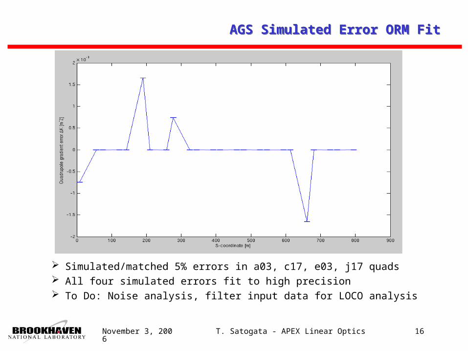
AGS Simulated Error ORM FitAGS Simulated Error ORM Fit
Simulated/matched 5% errors in a03, c17, e03, j17 quads All four simulated errors fit to high precision To Do: Noise analysis, filter input data for LOCO analysis
November 3, 2006
T. Satogata - APEX Linear Optics 17
ConclusionsConclusions
RHIC ORM Simulations RHIC storage lattice looks nondegenerate (even triplets) BPM/corrector gains, 0.1% gradient errors, and beta beating
correction can be found with realistic BPM noise (30um) RHIC ORM Data Analysis and APEX
Present analysis doubtful, converges to large (10%) errors Hand-correlate data to triple-check for oversights Reduce BPM average orbit noise (sampling, more
data/point) Parasitic setup/testing with Blue beam at injection 3h for ramping/store gradient error measurement/correction
RHIC AC Dipole APEX Parasitic (e.g. after) above ORM APEX, complementary
AGS ORM Studying extraction lattice, matches MAD-X Evaluating susceptibility to BPM noise Have ORM data in hand for analysis

November 3, 2006
T. Satogata - APEX Linear Optics 18
====================================================

November 3, 2006
T. Satogata - APEX Linear Optics 19
Twiss Parameter MeasurementsTwiss Parameter Measurements
Hoffstaetter, Keil, and Xiao (EPAC 2002) Iteratively fit cos/sin variations of (1) to measured Rij
Alternate between corrector and BPM (,) fitting Least-squares is solved with SVD of:
j
j
nn
nn
n
nnnj
j
j
g
f
R
R
R
)sin(sin2
)cos(sin2
......
)sin(sin2
)cos(sin2
)sin(sin2
)cos(sin2
/
...
/
/
11
11
1
1
00
00
0
0
11
00
22jjj gf )/arctan( jjj gf

November 3, 2006
T. Satogata - APEX Linear Optics 20
Response Matrix Dimensions at RHICResponse Matrix Dimensions at RHIC
Each RHIC ring has 334 BPM measurements (167 per plane) 234 correctors (117 per plane)
Total response matrix size is 78156 points APS/FNAL use only 25-40 correctors, all BPMs (Sajeev)
Fitting parameters 334 BPM measurement gains (offsets subtract out) 232 corrector strength gains (assume two are perfect) 117 path length changes for horizontal correctors 246 main/IR quadrupole gradients (or 72 IRs) (144 chromatic sextupole offsets)
Total fitting parameters: 929 (more or less)Total size of fit matrix: 78156*929 = 70 MpointsGrows larger very quickly with additional fit
parameters Minimize dimensionality to improve speed