
Linear motor for multi–car elevators: design and position...
12
Turk J Elec Eng & Comp Sci, Vol.19, No.6, 2011, c T ¨ UB ˙ ITAK doi:10.3906/elk-1007-594 Linear motor for multi–car elevators: design and position measurement ∗ C ¸a˘grıG ¨ URB ¨ UZ 1,† , Ender KAZAN 1 , Ahmet ONAT 1 , Sandor MARKON 2 1 Faculty of Engineering and Natural Sciences, Sabancı University, ˙ Istanbul, 34956, TURKEY e-mail: [email protected] 2 Graduate School of Information Technology, Kobe Institute of Computing, Kobe 650-0001, JAPAN Received: 20.07.2010 Abstract Multi-car elevator is an emerging technology consisting of two or more elevator cars moving independently in an elevator hoistway, which has become more appealing as building heights increase. In this paper, the design and drive methodologies for a linear motor driven multi-car elevator system with independently moving cars is introduced together with experimental results. Additionally, a safety method developed for the linear motor elevator and the conditions necessary for its proper operation are discussed. The new results introduced in this paper are in the areas of the designmethod of the linear motor for multi-car elevatorsystem, and the preliminary results for the position measurement system. Key Words: Linear motors, elevators, safety methods, design optimization, position measurement 1. Introduction Recent improvements in building technology has made it possible to increase heights considerably, with the current highest building in the world being higher than 800m. Although structural requirements are great in erecting such buildings, another very important aspect is one of logistics; i.e., how to allow for transport of goods and waste, of supplies such as energy and water and also of people into and out of the building, since the ratio of building volume to the area of transport passages diminishes. The transport passages mainly consist of elevator hoistways, and there can be a large number of dedicated hoistways in tall buildings, 50 being not uncommon. One of the main criteria for elevator performance is passenger hall-waiting time. To improve this performance several techniques such as express elevators which only serve specific floors or building sections are employed. However, as long as one elevator car is installed in a hoistway, these solutions give limited performance. One of the promising solutions is to install a large number of elevator cars in every hoistway (which may not overtake cars in front of themselves), and control them using a sophisticated group control ∗ This paper has been selected for publication in “The Special Issue” from TOK’09 (The 17th National IFAC Symposium on Automatic Control) † Corresponding author: Faculty of Engineering and Natural Sciences, Sabancı University ˙ Istanbul, 34956, TURKEY 827
Transcript of Linear motor for multi–car elevators: design and position...

Turk J Elec Eng & Comp Sci, Vol.19, No.6, 2011, c© TUBITAK
doi:10.3906/elk-1007-594
Linear motor for multi–car elevators: design and
position measurement∗
Cagrı GURBUZ1,†, Ender KAZAN1, Ahmet ONAT1, Sandor MARKON2
1Faculty of Engineering and Natural Sciences, Sabancı University, Istanbul, 34956, TURKEYe-mail: [email protected]
2Graduate School of Information Technology,Kobe Institute of Computing, Kobe 650-0001, JAPAN
Received: 20.07.2010
Abstract
Multi-car elevator is an emerging technology consisting of two or more elevator cars moving independently
in an elevator hoistway, which has become more appealing as building heights increase. In this paper, the
design and drive methodologies for a linear motor driven multi-car elevator system with independently moving
cars is introduced together with experimental results. Additionally, a safety method developed for the linear
motor elevator and the conditions necessary for its proper operation are discussed. The new results introduced
in this paper are in the areas of the design method of the linear motor for multi-car elevator system, and the
preliminary results for the position measurement system.
Key Words: Linear motors, elevators, safety methods, design optimization, position measurement
1. Introduction
Recent improvements in building technology has made it possible to increase heights considerably, with thecurrent highest building in the world being higher than 800m. Although structural requirements are great inerecting such buildings, another very important aspect is one of logistics; i.e., how to allow for transport ofgoods and waste, of supplies such as energy and water and also of people into and out of the building, since theratio of building volume to the area of transport passages diminishes. The transport passages mainly consistof elevator hoistways, and there can be a large number of dedicated hoistways in tall buildings, 50 being notuncommon.
One of the main criteria for elevator performance is passenger hall-waiting time. To improve thisperformance several techniques such as express elevators which only serve specific floors or building sectionsare employed. However, as long as one elevator car is installed in a hoistway, these solutions give limitedperformance. One of the promising solutions is to install a large number of elevator cars in every hoistway(which may not overtake cars in front of themselves), and control them using a sophisticated group control
∗This paper has been selected for publication in “The Special Issue” from TOK’09 (The 17th National IFAC Symposium onAutomatic Control)
†Corresponding author: Faculty of Engineering and Natural Sciences, Sabancı University Istanbul, 34956, TURKEY
827

Turk J Elec Eng & Comp Sci, Vol.19, No.6, 2011
algorithm [1, 2, 3, 4]. The conventional elevator mechanisms relying on ropes, pulleys and counterweights havelimitations on the number of cars that can be placed in the same hoistway. Therefore a new method, such aslinear motor driven elevator cars is needed [5].
The research on linear motors is new compared to rotational machines [6], and generally is handled incontexts where weight of the mover is not critical to performance which simplifies the design requirementsand analysis. Recently however, linear motors for drive of vertical loads in transportation have been alsostudied [7, 8, 9, 10] where high thrust to weight ratio is required. A strong candidate is permanent magnet
linear synchronous motors (PMLSM), which has become feasible in the recent years with the advances inpermanent magnet technology where high coercivity permanent magnet material with low cost has becomeavailable [8, 9, 11, 12, 13].
In multi–car elevator applications the elevator car must be free of any connections, mechanical orelectrical, to facilitate freedom in motion. This brings some interesting design requirements where safetydevices, position encoding, supplying power to car interior, communication of call buttons etc. must all beimplemented externally, from the stator side. All of these must be solved satisfactorily before successful designscan be produced. This constraint also mandates that the design must be a long armature type where the statorcontains the coils and the mover contains permanent magnets.
In this paper, we describe the main features of a linear motor designed for vertical transportationapplications, including safety [14, 15]. Then the optimization method used to design the new generation moveris introduced. Next we introduce a novel active position measurement method, where the stator itself is usedto determine the position of the mover which will be used for controlling at low speeds. Finally results of testsperformed on the actual full scale motor are given.
2. Safety system for linear motor elevators
Although the mover can be held stationary using electromagnetic force, an electromechanical brake for arrestingthe mover while the elevator is stopped at a floor is also necessary. However, because of the design requirementthat no electrical connections must be made to the elevator car, such a device cannot be installed on the moveritself, but must be on the stator side. A simple but expensive implementation is to build a solenoid operatedbrake with a length equal to the length of the stator.
Another solution is to re–design the stator and motor drive method such that its functionality is extendedbeyond only thrust generation, to also generate a virtual current vector along the top edge of the stator. Thiscan then be exploited on the mover by a suitable magnetic device to generate a sideways force and drive a brakemechanism.
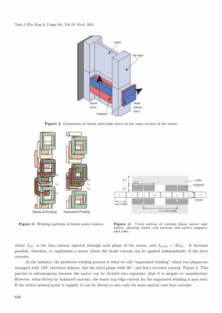
Special DC bias currents superposed on the drive currents can be used to generate a virtual brake currentalong the top edge of the stator which cause a force on a permanent magnet in its vicinity (Figure 2). Thepermanent magnet is in turn connected to a brake mechanism. The electromechanical structure of the brakeis such that in the absence of the DC bias currents, the brake is engaged and in their presence the brake isreleased. Using this method it becomes possible to generate thrust and operate the brake mechanism on thesame part of the motor section [15]. Such a brake mechanism can also be used to create safety zones on theelevator system, in which brakes will be applied to an elevator car and stopped unless the car has permissionto transit a given section of the stator.
The stator winding pattern required to generate the virtual current vector at the top edge of the stator
828

GURBUZ, KAZAN, ONAT, MARKON: Linear motor for multi–car elevators: design and...,
Figure 1. The linear motor designed for multi–car elevator applications.
will be explained next. The relationship of this current to the DC bias currents depends on the winding patternof the motor. We employ a winding pattern which we will call here “balanced winding”, consisting of coilswhere each phase is arranged at 120o electrical degrees as shown in Figure 3. For the balanced winding andthe conventionally defined motor phase currents ia , ib , ic , where ia(t) + ib(t) + ic(t) = 0 under normal driveconditions, the virtual current vector at the top edge of the stator becomes zero over a distance of one phaselength. However, if the neutral point of the motor is tapped to sink a DC current component through all phasecoils which we call the brake current Ibrake , then the virtual current becomes non–zero for any value of Ibrake .
Ibrake = ia(t) + IDC + ib(t) + IDC + ic(t) + IDC (1)
829
Turk J Elec Eng & Comp Sci, Vol.19, No.6, 2011
top edge
brakereleaseforce
thrustforce
stator
magnets
Figure 2. Generation of thrust and brake force on the same section of the stator.
c
a
bi
i
iaicibi
Balanced Winding Segmented Winding
w - v + u + w + v - u - w - v +
yokemagnet
coil width
L2
L1
L3
airgap
3 x coil width
Figure 3. Winding patterns of linear motor stators. Figure 4. Cross section of coreless linear motor andmover, showing stator coil sections and mover magnetsand yoke.
where IDC is the bias current injected through each phase of the motor, and Ibrake = 3IDC . It becomespossible, therefore, to implement a motor where the brake current can be applied independently of the drivecurrents.
In the industry, the preferred winding pattern is what we call “segmented winding” where two phases arearranged with 120o electrical degrees, but the third phase with 60o , and fed a reversed current, Figure 3. Thispattern is advantageous because the motor can be divided into segments, thus it is simpler to manufacture.However, when driven by balanced currents, the stator top edge current for the segmented winding is non–zero.If the motor neutral point is tapped, it can be driven to zero only for some special case bias currents.
830

GURBUZ, KAZAN, ONAT, MARKON: Linear motor for multi–car elevators: design and...,
The balanced winding is better suited for a safety brake operation on linear motor elevators sincegenerating a stator top field requires a special current pattern. The segmented winding on the other hand,will generate a zero stator top field in one special case current. In case of emergency where the motor or themotor driver is damaged or power is lost, there is a larger set of possible failure modes in which the balancedwinding will not be able to provide the special current pattern and thus the brake will engage to arrest the fallof the elevator car. Another advantage of balanced winding is that since the system is set up in such a way thatbrake is engaged for zero brake current and disengaged when brake current exceeds a certain value, there is noneed to supply brake current when the elevator car must be stopped [15].
3. Optimization method used to design the mover
For the air-core linear PM synchronous motor, a mover with iron yoke and permanent magnets is investigatedas shown in Figure 4. All of the dimensions which are the thickness of the magnet L1 , the width of the magnetL2 , and the thickness of the yoke L3 are treated as design variables. In general, thrust force is chosen as oneof the optimization objectives for linear motors, however we choose payload instead of thrust force as objectivesince the motor is designed for vertical transportation where how much load can be lifted is more importantthan how much force can be obtained. Consequently, the objectives of this optimization are chosen as highpayload P , low force ripple rd , low magnet weight Q and low brake effect eb described in Equations 2, 3, 4, 5.
P = F − Q (2)
rd = rd = (Fxmax − Fxmin) /Fxave × 100 (3)
eb = (F − Fb) /F × 100 (4)
Q = dm × Vm (5)
where F is the thrust force, Q is the total weight of one mover, Fxmax , Fxmin and Fxave are the maximum,the minimum and the average forces within the movement of one phase distance respectively. Fb is the thrustforce at the instant when the DC brake currents together with the AC drive currents are applied as describedin Section 2. Density and volume of the magnets are shown as dm and Vm respectively.
For the optimization, the variables are bounded as 10 ≤ L1 ≤ 40 , 20 ≤ L2 ≤ 60 and 10 ≤ L3 ≤ 40in mm. Instead of defining a continuous problem space including all of the three variables, an alternativeprocedure is followed where first L1 and L3 are optimized while holding L2 fixed at different values. Namely,for each L2 value, the values for L1 and L3 that give the highest payload are found. Then, by comparing theperformance on all the objectives at different values, the optimum value for L2 is found. The main advantageof this procedure is reduced search space and prioritizing high payload over other objectives. The reason foroptimizing L2 variable after L1 and L3 is its higher effect on all of the objectives. The search algorithmto determine the thickness of magnet, L1 , and, yoke L3 , is given in Figure 5. For a given L1 and L2 , thethickness of the yoke (i.e. L3 ) can be increased as long as there is still increase in payload. Although largeryoke thicknesses after this point give higher thrust forces, we define this point as the optimal value since theincrease in weight of the mover is larger than the increase in thrust force which is not desirable for higherpayload objective. Similarly, the same algorithm can be applied for determining the optimal value of magnetthickness L1 . However, there is still need to determine optimal L3 again for each L1 to be compared. Theoptimal L1 and L3 values calculated for each L2 are given in Table 1.
831

Turk J Elec Eng & Comp Sci, Vol.19, No.6, 2011
Increase the Yoke Thickness
Analyse the Payload
Did Payload Increase?Yes
Output the previous value
No
Increase the Magnet Thickness
Did Payload Increase?Yes
No
Set previous value as optimal
Increase the Magnet Width
Figure 5. Finding optimal magnet and yoke thicknesses regarding to payload.
Table 1. Optimal values of L1 and L3 with respect to L2 .
L2(mm) 20 24 28 32 36 40 44 48 52 56 60L1(mm) 34 30 30 30 28 28 28 28 28 30 28L3(mm) 12 14 16 18 20 22 24 24 24 24 22
0
10
20
30
40
50
60
0
2
4
6
8
10
12
14
16
18
20
18 20 22 24 26 28 30 32 34 36 38 40 42 44 46 48 50 52 54 56 58 60 62
Payl
oad
(kg)
Forc
e R
ippl
e an
d B
rake
Eff
ect (
%)
Magnet Witdh (mm)
force ripple(%) brake effect(%) payload(kg)
Figure 6. Change of objectives vs magnet width. Figure 7. Final coil shape used for the stator.
Once the optimal values of magnet and yoke thicknesses (L1 and L3 ) are determined, the objectives canbe analyzed for comparison of magnet width L2 to find the final optimal solution. The results of objectiveswith respect to L2 variable are found by a 2D FEM software [16] shown in Figure 6. It can be seen that all ofthe objective functions have different trends over L2 . Therefore, there is need for a multi-objective optimization
832

GURBUZ, KAZAN, ONAT, MARKON: Linear motor for multi–car elevators: design and...,
switch
Figure 8. Motor driver, for the brake operation discussed.
with a cost function which can be defined as,
Wmw = k1W1 + k2W2 + k3W3 + k4W4 (6)
where,
W1 = eb (7)
W2 = rd (8)
W3 = 1/P (9)
W4 = Q (10)
In the cost function, it is important to reduce W3 and W4 in order to reduce the running costs and initialcosts respectively. On the other hand, it is also important to reduce W1 and W2 for the sake of controllability.Therefore, k1 ...k4 can be chosen with respect to the desired weights of costs and controllability of the motor [17].
4. Implementation of the linear motor
The stator coil shape is important in the implementation of the linear motor. It defines the performance of themotor including the brake and thrust forces, and also the cost of the completed unit based on its complexity.Here the design for the full scale experimental test motor and its special driver topology will be explained.
Several coil shapes were considered for the stator. Although initial designs consisted of complex shapedcoils with different shapes for each phase, final design shown in Figure 7 was eventually reached. It consists ofa simple, single coil shape repeated to construct a balanced winding stator.
As discussed in Section 2, brake currents must flow into the neutral point of the motor, superposed on theusual balanced drive currents. To make this possible, the neutral point of the motor was connected to ground orDC link, over an extra switch on the motor that we call the “seventh switch” and a ballast inductor, as shownin Figure 8. To produce brake currents, the mid part of the center aligned PWM cycle when all motor coils areconnected to DC link is used. During this time period, the seventh switch is closed for a suitable duration. Asanother strategy, it is also possible to generate thrust and brake forces using a different part of the stator thanthat used for thrust generation.
5. Position sensing
It is desirable to drive linear motors with no electrical connections between the mover and stator. However, mostposition sensing methods available [18] rely on a stationary passive position reference such as the grated strip
833

Turk J Elec Eng & Comp Sci, Vol.19, No.6, 2011
of an incremental encoder and an active part attached to the mover, where a flexible cable must be connectedto the mover of the motor.
In this section, the principle of operation and the methodology of the development and testing of apassive position sensor system that uses one non-active linear motor stator segment in front of or behind themover will be given. The sensing operates on the principle of measuring the variation of the mutual inductancebetween different coils of the stator, when a magnetic shunt in the form of ferromagnetic material fixed at apredetermined distance ahead of the mover moves along them. The measurement is sufficiently accurate andreliable to supplement a sensorless position control scheme, as a backup scheme. By combining two completelydifferent position sensing methods, the total system is judged to be safe to be used in a passenger elevator.
When we deliberately introduce physical asymmetry into the system of magnetic circuit of the statorcoils, it causes the terminal parameters also to show asymmetrical behavior. We can infer information aboutthe conditions causing the asymmetry, by measuring the terminal parameter values. Let us consider the case ofplacing a block of soft magnetic material in the vicinity of the linear motor armature winding (Figure 9). Whenwe apply a sinusoidal current into one phase coil and analyze the field distribution, an asymmetric variationdepending on the position of the ferromagnetic block can be clearly seen. The finite element magnetic analysissoftware “FEMM” [16] was used to analyze the field distribution in a 2-dimensional approximation, the crosssection of the stator, to generate Figure 9, with the ferromagnetic block placed in an asymmetric position. Inthe following, we call that block a “magnetic shunt”. Since the mover is fixed at a known distance away fromthe magnetic shunt, by measuring the position of the shunt, the position of the mover can easily be calculated.
Figure 9. Model of linear motor armature with magnetic shunt, showing cross section through motor coils and shunt.
The method can be analyzed similar to the measurement of mutual inductance between two coils asshown in Figure 10. When a sinusoidal voltage is applied to one of the coils, the induced voltage at the otherside depends on the mutual inductance. The mutual inductance in this case depends, in turn, on the positionof the magnetic shunt.
L1 L2
V1V2
i1
Figure 10. Setup for measuring mutual inductance.
The equations of the circuit are given in Eqs. 11 and 12:
834

GURBUZ, KAZAN, ONAT, MARKON: Linear motor for multi–car elevators: design and...,
V1 = R1i1 + L1di1dt
+ Mdi2dt
(11)
V2 = R2i2 + L2di2dt
+ Mdi1dt
(12)
From the analysis mentioned above, we can calculate the induced voltages across the two other motorphases for each magnetic shunt position. When we move the magnetic shunt across the length of the armature,these voltages will change accordingly. The expected values of induced voltages can be calculated or measuredbeforehand, and placed in a look-up table. During the operation, the measured induced voltages can be comparedto those in the table, and the position of the magnetic shunt can be found by a search algorithm. Instead ofusing a ferromagnetic shunt, a diamagnetic shunt can also be used, which would have the reverse effect onbreaking the symmetry of the magnetic field.
6. Results
In this section we present results about the generated brake force, a comparison of the generated thrust force withrespect to the simulation results, and the results of the active position sensing method discussed in Section 5. Thesimulated and experimental results are based on the full scale motor designed using the method as describedin this paper, except the brake force data, which was generated using an earlier motor, also designed andimplemented by the authors.
The brake force should ideally remain constant with respect to mover position, and change linearly withrespect to brake current. To measure these performance values, a magnet plate with N38 type magnets wasbuilt and mounted on the mover using a linear bearing movable perpendicular to the direction of motion. Thesideways force was measured using a strain gage. The position along the stator was measured using a linearposition encoder. Brake forces were applied to each coil separately using voltage supplies. The brake force withrespect to brake plate position on the stator can be seen in Figure 11. The brake force does not vary muchwhen the mover advances on the stator. However, the brake force is not large. Therefore a brake system witha carefully designed mechanical advantage is necessary. Also the brake plate magnetic design can be improvedto increase the brake force.
In Figure 12, the change in brake force with respect to brake current while the mover is in a fixed positioncan be seen. The change in brake force with respect to brake current is linear.
The payload performance of a linear motor for vertical applications is important. A mover was designedaccording to the method summarized in Section 3. The thrust force was measured by applying a current of3A to the stator and increasing the downward force on the mover while observing the vertical displacement.The mover shifted to a lower position as force is increased, and just after the maximum thrust force, it slips.This test was repeated for two air gap values, 19mm and 14mm. Smaller air gaps are advantageous but may bedifficult to obtain due to manufacturing tolerances. The design gap for this motor was 14mm, which includesthe thickness of the stator.
Results of this test can be seen in Figure 13. The total capability of 19mm mover is 53kg, while for14mm, it is possible to carry 59kg of weight (since the optimization did not include the dead weight of the
mover support structure, it is added to the thrust force). The simulation results show that the same movershould be capable of lifting 54kg for 19mm, and 58kg for 14mm air gaps. These results suggest that this slotlessmotor design is well suited to 2D FEM analysis. Although the payload capacity of the designed movers is high,
835

Turk J Elec Eng & Comp Sci, Vol.19, No.6, 2011
0 20 40 60 800
40
80
120
160
200
Position[mm]
Bra
ke f
orce
[gr]
measuredfitted
0 0.5 1 1.5 2 2.50
75
150
225
300
Current[A]
Bra
ke f
orce
[gr]
measuredfitted
Figure 11. Distribution of brake force. Figure 12. Brake force with respect to brake current.
15
20
25
30
35
40
45
50
55
60
0 5 10 15 20 25 30Mover vertical displacement (mm)
Payl
oad
(kg)
Figure 13. Motor payload for different air gap values for 3A current.
the payload can be linearly and inexpensively increased by mechanically connecting several movers together,with one phase length separation [15]. Using such an arrangement, the weight of one person can easily be liftedusing three movers.
For position sensing we have tested the method that we described in previous section on a linear motorwith dimensions shown in Table 2.
One coil of Phase B was fed with 1kHz sinusoidal current, and the induced voltages in one coil each ofPhase A and Phase C were measured. Since the excitation would cause eddy currents in a solid iron core, alaminated magnetic shunt was used to reduce their effect.
The result shown in Figure 14 is obtained with a laminated magnetic shunt of iron. For this ironlamination fill factor is 0.9 and the lamination thickness is 1 mm. We have found that the position sensing isfeasible.
The locus of the two voltages is shown in Figure 15. In principle, by measuring the voltages, we can readout the position if this curve is labeled with measured shunt positions.
836

GURBUZ, KAZAN, ONAT, MARKON: Linear motor for multi–car elevators: design and...,
Table 2. Dimensions of the tested motor.
Phases 3Stator width 200 mmStator thickness 10 mmPole pitch 60 mmWidth of magnetic shunt 20 mmLength of magnetic shunt 190 mmThickness of magnetic shunt 40 mm
270 280 290 300 310 320 330 340 3500.18
0.2
0.22
0.24
0.26
0.28
0.3
Uvoltage and Vvoltage vs Position
Position[mm]
Uvo
ltage
and
Vvo
ltage
[V]
U voltage
V voltage
0.18 0.2 0.22 0.24 0.26 0.28 0.30.18
0.2
0.22
0.24
0.26
0.28
0.3Uvoltage vs Vvoltage
Uvoltage [V]
Vvo
ltage
[V]
Figure 14. Induced terminal voltages of coil A and C
with respect to shunt position.
Figure 15. Parametric representation of the data in Fig-
ure 14, showing voltages of coils A and C with respect to
each other as shunt is moved.
7. Conclusions
In this paper, we describe the main features of a linear motor designed for vertical transportation applications,including safety. Also a mover optimization method for designing the mover is introduced. Depending on thecost function, how we can find optimal mover structure for different features (e.g force ripple, payload, thrust
force etc.) is explained. Once the optimal parameters of the mover are determined, the importance of thecoil shapes for implementation of the linear motor is explained. Also the effect of the coil shape on the brakemechanism is represented. The idea was supported by methodology of new position sensing method followedby simulations and experimental results.
It has been inferred that the linear motor system can operate both propulsion and safety system withdifferent optimization of mover. Further research will be done to operate this system according to the newposition sensing method, and thus to satisfy the idea of ropeless linear motor. Furthermore, we are still workingon the optimization of mover, position sensing method and safety system.
It has been observed that the proposed system can successfully operate as a combined propulsion andsafety system. Further research will be done to validate the operation of the safety system for all failure modes,and thus to satisfy the requirements for certification. Furthermore, we are working on the modification of theoptimization procedure to include directly the cost of the stator, which will become an important factor whenapplying the results of this research to elevators of extreme high-rise buildings.
837
Turk J Elec Eng & Comp Sci, Vol.19, No.6, 2011
Acknowledgments
This research was supported in part by Fujitec Co., Ltd. of Japan.
References
[1] T. Ishii, “Elevators for skyscrapers,” Spectrum, IEEE, vol. 31, no. 9, pp. 42–46, 1994.
[2] W. Jones, “How to build a mile-high skyscraper,” Spectrum, IEEE, vol. 44, no. 6, pp. 52–53, 2007.
[3] S. Markon, H. Kita, and H. Kise, Control of Traffic Systems in Buildings: Applications of Modern Supervisory and
Optimal Control (Advances in Industrial Control). NJ, USA: Springer-Verlag New York, Inc., 2006.
[4] S. Takahashi, H. Kita, H. Suzuki, T. Sudo, and S. Markon, “Simulation-based optimization of a controller for
multi-car elevators using a genetic algorithm for noisy fitness function,” in The 2003 Congress on Evolutionary
Computation, CEC ’03, vol. 3, 2003, pp. 1582–1587.
[5] M.Miyatake, T.Koseki, and S.Sone, “Design and traffic control of multiple cars for an elevator system driven by
linear synchronous motors,” in Proc.Symposium on Linear Drives for Industry Applications, no. AP-22, 1998, pp.
94–97.
[6] I. Boldea and S. Nasar, Linear motion electromagnetic devices. Taylor & Francis, 2001.
[7] J. F. Gieras and Z. J. Piech, Linear synchronous motors: transportation and automation systems. CRC Press,
2000.
[8] H. Yamaguchi, H. Osawa, T. Watanabe, and H. Yamada, “Power supply of long stator linear motors application to
multi mobile system,” in Proc. AMC96, 1996, pp. 441–446.
[9] S. Chevailler, M. Jufer, and Y. Perriard, “Linear motors for multi mobile systems,” in IAS2005, 2005, pp. 2099–2106.
[10] A. Cassat, B. Kawkabani, Y. Perriard, and J.-J. Simond, “Power supply of long stator linear motors - application
to multi mobile system,” in Industry Applications Society Annual Meeting, 2008. IAS ’08. IEEE, 2008, pp. 1–7.
[11] K. Yoshida and X. Zhang, “Sensorless guidance control with constant airgap in ropeless linear elevator,” in The 4th
International Power Electronics and Motion Control Conference, vol. 2, 2004, pp. 772–776.
[12] N. Takahashi, T. Yamada, D. Miyagi, and S. Markon, “Basic study of optimal design of linear motor for rope-less
elevator,” in 7th International Conference on Computation in Electromagnetics, 2008, pp. 202–203.
[13] K. B.Quan, H. X.Zhen, W. Hong-xing, and L. Li-yi, “Thrust and thermal characteristics of electromagnetic launcher
based on permanent magnet linear synchronous motors,” Magnetics, IEEE Transactions on, vol. 45, no. 1, pp. 358–
362, 2009.
[14] S. Markon, Y. Komatsu, A. Onat, A. Yamanaka, and E. Kazan, “Linear motor coils as brake actuators for multi-car
elevators,” in Proc. LDIA, 2007, pp. 73–74.
[15] A. Onat, E. Kazan, N. Takahashi, D. Miyagi, and Y. Komatsu, “Design and implementation of a linear motor for
multi-car elevators,” Mechatronics, IEEE Transactions on, accepted for publication.
[16] D. C. Meeker, “Finite element method magnecits, version 4.2 (02nov2009 build).”
[17] E. Kazan, “Design and implementation of a linear motor for multi–car elevators,” Master’s thesis, Sabanci University,
Istanbul, Turkey, July 2009.
[18] D. Nyce, Linear Position Sensors: Theory and Application. USA: Wiley Interscience, 2004.
838