Linear Escalator Brochure
10
SERIES SERIES Z ESCALA TORS For USA For USA
Transcript of Linear Escalator Brochure
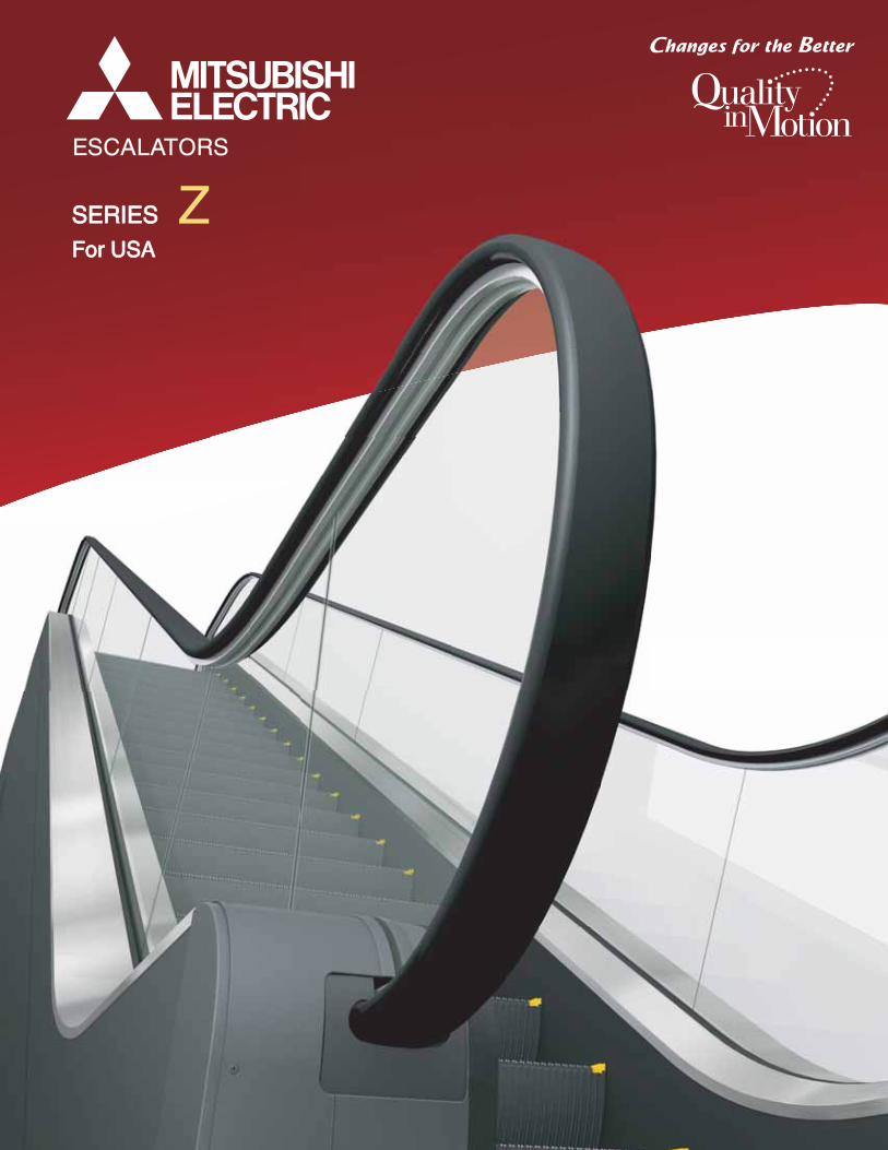
SERIES SERIES ZESCALATORS
For USAFor USA
L-170-8-C81071-A IN-0808 Printed in Japan (INADEN) ©2008 Mitsubishi Electric Corporation
New publication, effective Aug. 2008.Specifications subject to change without notice.
http://www.mitsubishi-elevator.com/
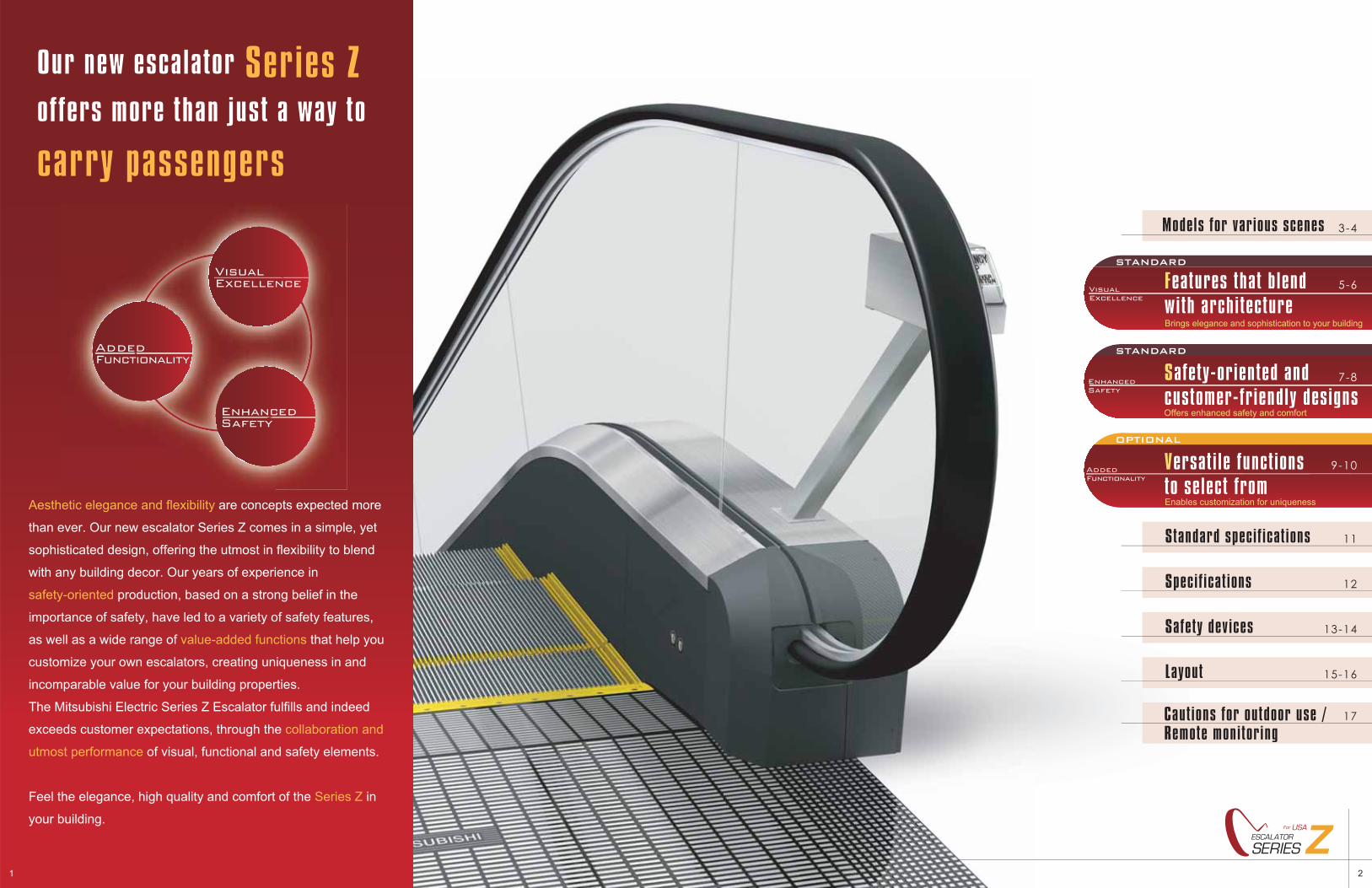
Our new escalator Series Zoffers more than just a way to carry passengers
Aesthetic elegance and flexibility are concepts expected more
than ever. Our new escalator Series Z comes in a simple, yet
sophisticated design, offering the utmost in flexibility to blend
with any building decor. Our years of experience in
safety-oriented production, based on a strong belief in the
importance of safety, have led to a variety of safety features,
as well as a wide range of value-added functions that help you
customize your own escalators, creating uniqueness in and
incomparable value for your building properties.
The Mitsubishi Electric Series Z Escalator fulfills and indeed
exceeds customer expectations, through the collaboration and
utmost performance of visual, functional and safety elements.
Feel the elegance, high quality and comfort of the Series Z in
your building.
Versatile functionsto select fromEnables customization for uniqueness
9-10AddedFunctionality
3-4
11
17
Models for various scenes
Standard specifications
Cautions for outdoor use /Remote monitoring
12Specifications
13-14Safety devices
15-16Layout
Features that blendwith architectureBrings elegance and sophistication to your building
5-6VisualExcellence
STANDARD
OPTIONAL
Safety-oriented andcustomer-friendly designsOffers enhanced safety and comfort
7-8EnhancedSafety
STANDARD
VisualExcellence
EnhancedSafety
AddedFunctionality
21
ZZSERIESESCALATOR
For USA
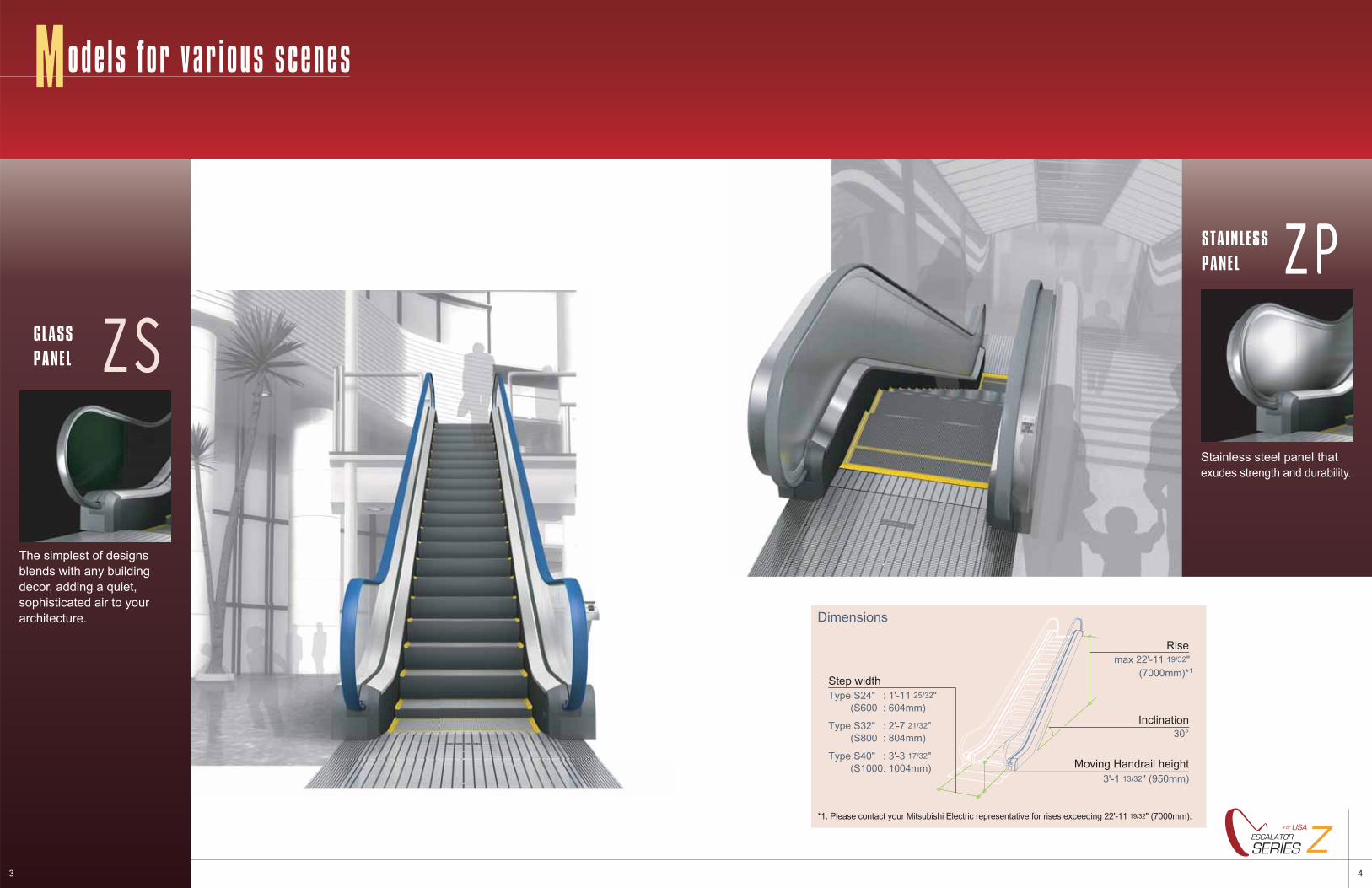
Dimensions
max 22'-11 19/32" (7000mm)*1
30°
3'-1 13/32" (950mm)
Step width
Moving Handrail height
Inclination
Rise
*1: Please contact your Mitsubishi Electric representative for rises exceeding 22'-11 19/32" (7000mm).
Type S24" : 1'-11 25/32"(S600 : 604mm)
Type S32" : 2'-7 21/32" (S800 : 804mm)
Type S40" : 3'-3 17/32" (S1000: 1004mm)
The simplest of designsblends with any buildingdecor, adding a quiet,sophisticated air to yourarchitecture.
ZSZSGLASSPANEL
ZPZPSTAINLESSPANEL
Stainless steel panel that exudes strength and durability.
43
ZSERIESESCALATOR
For USA
Models for var ious scenes
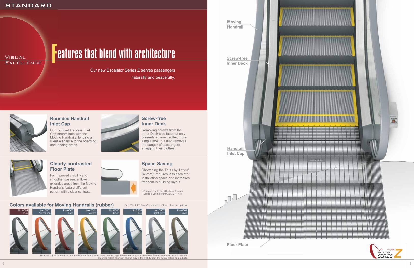
HandrailInlet Cap
Floor Plate
Screw-free Inner Deck
MovingHandrail
65
ZZSERIESESCALATOR
For USA
Colors available for Moving Handrails (rubber)No.0001
BlackNo.0502
VermilionNo.0503
RedNo.0504
YellowNo.0505
GreenNo.0506
BlueNo.0507
Light grayNo.0508
Brown
Space SavingShortening the Truss by 1 25/32" (45mm)* requires less escalator installation space and increases freedom in building layout.
Clearly-contrastedFloor PlateFor improved visibility and smoother passenger flows, extended areas from the Moving Handrails feature different pattern with a clear contrast.
Rounded HandrailInlet CapOur rounded Handrail Inlet Cap streamlines with the Moving Handrails, lending a silent elegance to the boarding and landing areas.
Screw-freeInner DeckRemoving screws from the Inner Deck side face not only presents an even softer, more simple look, but also removes the danger of passengers snagging their clothes.
Handrail colors shown in photos may differ slightly from the actual colors on products.Handrail colors for outdoor use are different from these shown on this page. Please contact your Mitsubishi Electric representative for details.
Only "No. 0001 Black" is standard. Other colors are optional.
* Compared with the Mitsubishi Electric Series J Escalator (for ASME A17.1).
Our new Escalator Series Z serves passengers
naturally and peacefully.
VisualExcellence Features that blend with architecture
STANDARD
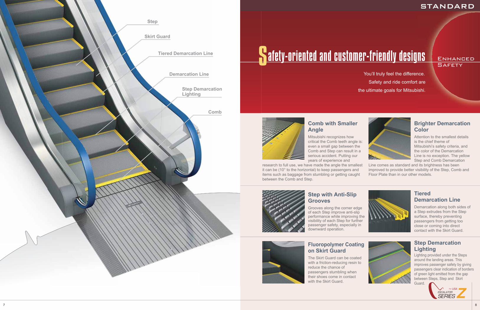
Step
Step Demarcation Lighting
Tiered Demarcation Line
Demarcation Line
Comb
Skirt Guard
87
ZZSERIESESCALATOR
For USA
Fluoropolymer Coating on Skirt GuardThe Skirt Guard can be coated with a friction-reducing resin to reduce the chance of passengers stumbling when their shoes come in contact with the Skirt Guard.
Step with Anti-SlipGroovesGrooves along the corner edge of each Step improve anti-slip performance while improving the visibility of each Step for further passenger safety, especially in downward operation.
Tiered Demarcation LineDemarcation along both sides of a Step extrudes from the Step surface, thereby preventing passengers from getting too close or coming into direct contact with the Skirt Guard.
Lighting provided under the Steps around the landing areas. This improves passenger safety by giving passengers clear indication of borders of green light emitted from the gap between Steps, Step and Skirt Guard.
Step Demarcation Lighting
Comb with Smaller AngleMitsubishi recognizes how critical the Comb teeth angle is: even a small gap between the Comb and Step can result in a serious accident. Putting our years of experience and
research to full use, we have made the angle the smallest it can be (10° to the horizontal) to keep passengers and items such as baggage from stumbling or getting caught between the Comb and Step.
Brighter Demarcation ColorAttention to the smallest details is the chief theme of Mitsubishi’s safety criteria, and the color of the Demarcation Line is no exception. The yellow Step and Comb Demarcation
Line comes as standard and its brightness has been improved to provide better visibility of the Step, Comb and Floor Plate than in our other models.
EnhancedSafety
You’ll truly feel the difference.
Safety and ride comfort are
the ultimate goals for Mitsubishi.
Safety-oriented and customer-friendly designs
STANDARD
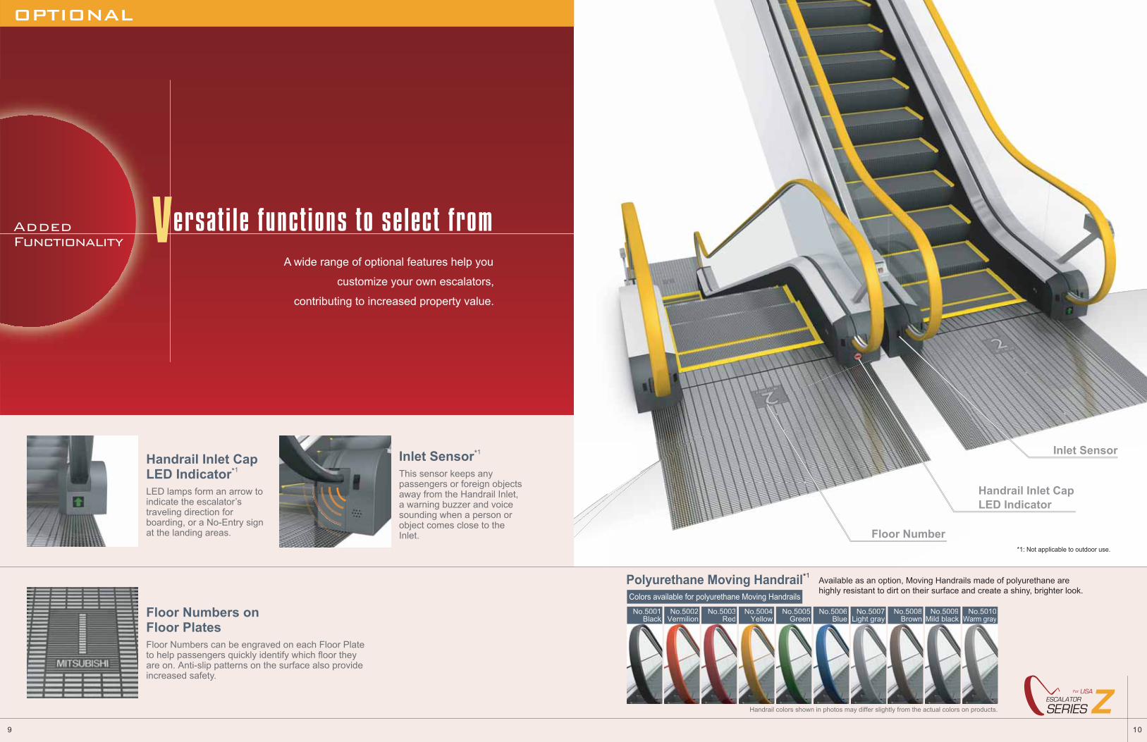
Handrail Inlet Cap LED Indicator
Inlet Sensor
Floor Number*1: Not applicable to outdoor use.
109
ZZSERIESESCALATOR
For USA
No.5001Black
No.5002Vermilion
No.5003Red
No.5004Yellow
No.5005Green
No.5006Blue
No.5007Light gray
No.5009Mild black
No.5008Brown
No.5010Warm gray
Handrail colors shown in photos may differ slightly from the actual colors on products.
Colors available for polyurethane Moving Handrails
Polyurethane Moving Handrail*1Available as an option, Moving Handrails made of polyurethane arehighly resistant to dirt on their surface and create a shiny, brighter look.
Handrail Inlet CapLED Indicator*1
LED lamps form an arrow to indicate the escalator’s traveling direction for boarding, or a No-Entry sign at the landing areas.
Inlet Sensor*1
This sensor keeps any passengers or foreign objects away from the Handrail Inlet, a warning buzzer and voice sounding when a person or object comes close to the Inlet.
Floor Numbers onFloor PlatesFloor Numbers can be engraved on each Floor Plate to help passengers quickly identify which floor they are on. Anti-slip patterns on the surface also provide increased safety.
A wide range of optional features help you
customize your own escalators,
contributing to increased property value.
Versatile functions to select fromAddedFunctionality
OPTIONAL
Deck Board(Inner Deck)
Corner Deck
Moving Handrail
Guard Rail
Interior Panel
Deckboard(Outer Deck)
Stainless steelhairline
Stainless steelhairline
Stainless steelhairline
Stainless steelhairline
Stainless steelhairline
Moving Handrail
Guard Rail
Stainless steelhairline
Interior Panel
Deck Board(Inner Deck)
Deck Board(Outer Deck)
Transparent tempered glass
Stainless steelhairline
Stainless steelhairline
ZPZS
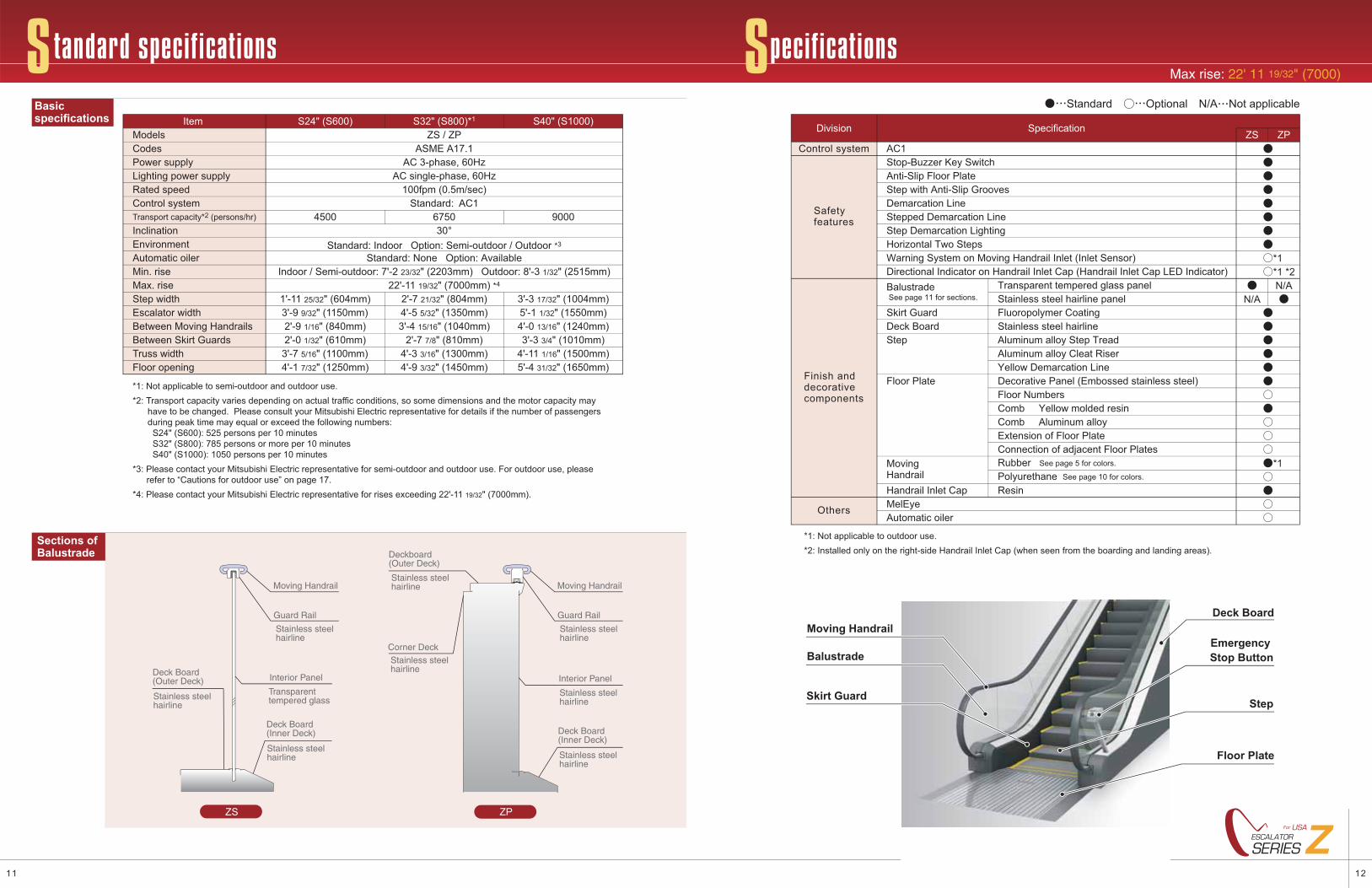
Standard specifications SpecificationsMax rise: 22' 11 19/32" (7000)
S24" (S600) S32" (S800)*1 S40" (S1000)Item
AC 3-phase, 60HzAC single-phase, 60Hz
100fpm (0.5m/sec)Standard: AC1
4500 6750 9000
1'-11 25/32" (604mm) 2'-7 21/32" (804mm) 3'-3 17/32" (1004mm)3'-9 9/32" (1150mm) 4'-5 5/32" (1350mm) 5'-1 1/32" (1550mm)2'-9 1/16" (840mm) 3'-4 15/16" (1040mm) 4'-0 13/16" (1240mm)2'-0 1/32" (610mm) 2'-7 7/8" (810mm) 3'-3 3/4" (1010mm)
3'-7 5/16" (1100mm) 4'-3 3/16" (1300mm) 4'-11 1/16" (1500mm)4'-1 7/32" (1250mm) 4'-9 3/32" (1450mm) 5'-4 31/32" (1650mm)
Power supply
ModelsCodes
Lighting power supplyRated speedControl systemTransport capacity*2 (persons/hr)
InclinationEnvironmentAutomatic oilerMin. riseMax. riseStep widthEscalator widthBetween Moving HandrailsBetween Skirt GuardsTruss widthFloor opening
Sections of Balustrade
Basicspecifications
Indoor / Semi-outdoor: 7'-2 23/32" (2203mm) Outdoor: 8'-3 1/32" (2515mm)22'-11 19/32" (7000mm) *4
Standard: Indoor Option: Semi-outdoor / Outdoor *3
Standard: None Option: Available
30°
ZS / ZPASME A17.1
*1: Not applicable to semi-outdoor and outdoor use.*2: Transport capacity varies depending on actual traffic conditions, so some dimensions and the motor capacity may have to be changed. Please consult your Mitsubishi Electric representative for details if the number of passengers during peak time may equal or exceed the following numbers: S24" (S600): 525 persons per 10 minutes S32" (S800): 785 persons or more per 10 minutes S40" (S1000): 1050 persons per 10 minutes*3: Please contact your Mitsubishi Electric representative for semi-outdoor and outdoor use. For outdoor use, please refer to “Cautions for outdoor use” on page 17.*4: Please contact your Mitsubishi Electric representative for rises exceeding 22'-11 19/32" (7000mm).
1211
ZZSERIESESCALATOR
For USA
AC1
N/AN/A
Control system
Safetyfeatures
Finish anddecorativecomponents
*1: Not applicable to outdoor use.*2: Installed only on the right-side Handrail Inlet Cap (when seen from the boarding and landing areas).
Others
SpecificationDivision ZS ZP●●●●●●●●
●●
●●●●●●
●
●
Stop-Buzzer Key Switch
Step with Anti-Slip GroovesAnti-Slip Floor Plate
Step Demarcation Lighting
Demarcation Line
Horizontal Two StepsWarning System on Moving Handrail Inlet (Inlet Sensor)
Stepped Demarcation Line
Directional Indicator on Handrail Inlet Cap (Handrail Inlet Cap LED Indicator)
Deck BoardStep
Floor Plate
Handrail Inlet Cap
MovingHandrail
Rubber See page 5 for colors.
Polyurethane See page 10 for colors.
Skirt Guard
Balustrade See page 11 for sections.
MelEyeAutomatic oiler
Transparent tempered glass panelStainless steel hairline panel
Stainless steel hairlineAluminum alloy Step TreadAluminum alloy Cleat RiserYellow Demarcation LineDecorative Panel (Embossed stainless steel)Floor NumbersComb Yellow molded resinComb Aluminum alloyExtension of Floor Plate
Resin
Fluoropolymer Coating
Standard ○ Optional N/A Not applicable
*1○
*1●
○
○○○
○
*1 *2○
Connection of adjacent Floor Plates
○○
Moving HandrailDeck Board
Step
Emergency Stop Button
Floor Plate
Balustrade
Skirt Guard
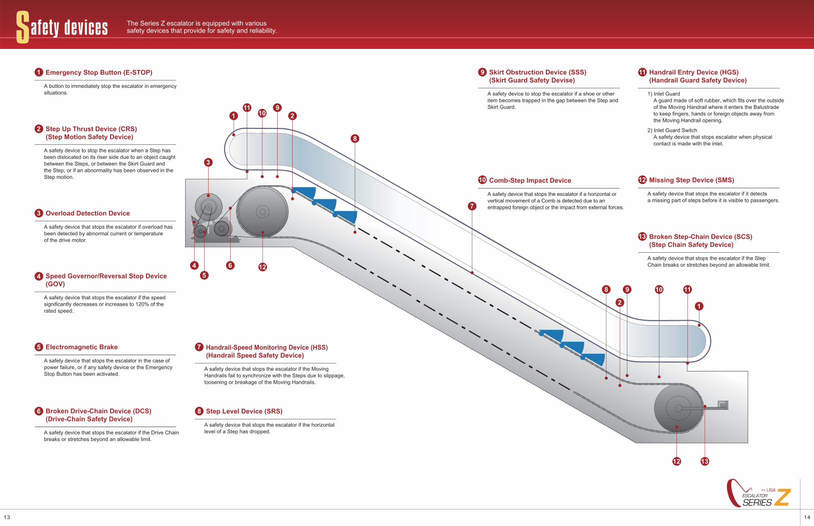
OPTIONALThe Series Z escalator is equipped with various safety devices that provide for safety and reliability.Safety devices
1
7
8
8
9
9
10
10
11
11
12
12
13
2
12
3
45
6
● Broken Step-Chain Device (SCS) (Step Chain Safety Device)
A safety device that stops the escalator if the Step Chain breaks or stretches beyond an allowable limit.
13
● Missing Step Device (SMS)
A safety device that stops the escalator if it detects a missing part of steps before it is visible to passengers.
12● Comb-Step Impact Device
A safety device that stops the escalator if a horizontal or vertical movement of a Comb is detected due to an entrapped foreign object or the impact from external forces.
10
● Skirt Obstruction Device (SSS) (Skirt Guard Safety Devise)
A safety device to stop the escalator if a shoe or other item becomes trapped in the gap between the Step and Skirt Guard.
9
● Step Level Device (SRS)
A safety device that stops the escalator if the horizontal level of a Step has dropped.
8
● Handrail-Speed Monitoring Device (HSS) (Handrail Speed Safety Device)
A safety device that stops the escalator if the Moving Handrails fail to synchronize with the Steps due to slippage, loosening or breakage of the Moving Handrails.
7
A safety device that stops the escalator if the Drive Chain breaks or stretches beyond an allowable limit.
● Broken Drive-Chain Device (DCS) (Drive-Chain Safety Device)6
● Emergency Stop Button (E-STOP)
A button to immediately stop the escalator in emergency situations.
1
● Step Up Thrust Device (CRS) (Step Motion Safety Device)
A safety device to stop the escalator when a Step has been dislocated on its riser side due to an object caught between the Steps, or between the Skirt Guard and the Step, or if an abnormality has been observed in the Step motion.
2
● Overload Detection Device
A safety device that stops the escalator if overload has been detected by abnormal current or temperature of the drive motor.
3
A safety device that stops the escalator if the speed significantly decreases or increases to 120% of the rated speed.
● Speed Governor/Reversal Stop Device (GOV)4
● Electromagnetic Brake
A safety device that stops the escalator in the case of power failure, or if any safety device or the Emergency Stop Button has been activated.
5
● Handrail Entry Device (HGS) (Handrail Guard Safety Device)
1) Inlet GuardA guard made of soft rubber, which fits over the outside of the Moving Handrail where it enters the Balustrade to keep fingers, hands or foreign objects away from the Moving Handrail opening.
2) Inlet Guard SwitchA safety device that stops escalator when physical contact is made with the inlet.
11
1413
ZZSERIESESCALATOR
For USA
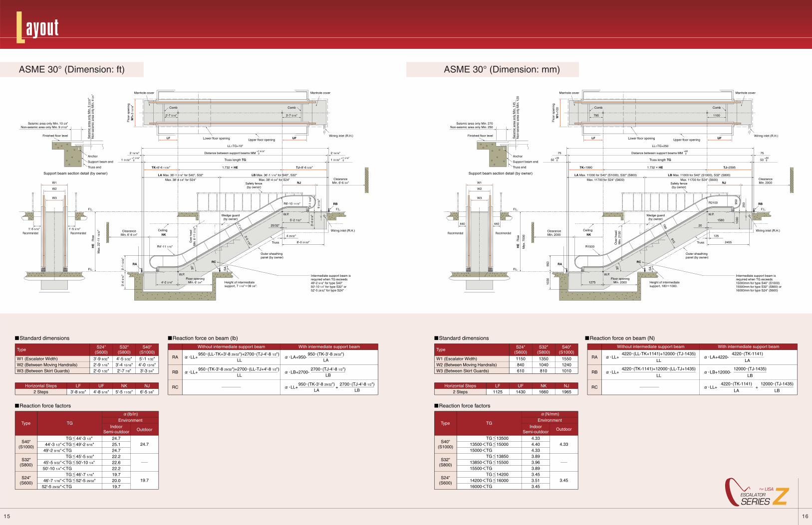
Layout
ASME 30° (Dimension: mm)ASME 30° (Dimension: ft)
TG 1350013500 TG 1500015000 TG TG 1385013850 TG 1550015500 TG TG 1420014200 TG 1600016000 TG
4.33
3.45
1150840610
13501040810
155012401010
Standard dimensions
W1 (Escalator Width)W2 (Between Moving Handrails)W3 (Between Skirt Guards)
IndoorSemi-outdoor
Outdoor
Reaction force on beam (N)
TypeWith intermediate support beam
LA+4220-4220 (TK-1141)
LA
LB+12000-12000 (TJ-1435)
LB
4220 (TK-1141)
LALL+ +
12000 (TJ-1435)
LB
4220 (LL-TK+1141)+12000 (TJ-1435)
LLLL+
4220 (TK-1141)+12000 (LL-TJ+1435)
LLLL+
RA
RB
RC
Without intermediate support beam
Reaction force factors
Type TG
(N/mm)Environment
4.334.404.333.893.963.893.453.513.45
S24"(S600)
S32"(S800)
S40"(S1000)
S40"(S1000)
S24"(S600)
S32"(S800)
2 Steps 1125 1430 1660 1965Horizontal Steps LF UF NK NJ
19.7
24.7S40"
(S1000)
S24"(S600)
S32"(S800)
3'-9 9/32"2'-9 1/16"2'-0 1/32"
4'-5 5/32"3'-4 15/16"2'-7 7/8"
5'-1 1/32"4'-0 13/16"3'-3 3/4"
Standard dimensions
W1 (Escalator Width)W2 (Between Moving Handrails)W3 (Between Skirt Guards)
2 Steps 3'-8 9/32" 4'-8 5/16" 5'-5 11/32" 6'-5 3/8"
IndoorSemi-outdoor Outdoor
Reaction force on beam (lb)
TypeWith intermediate support beam
LA+950-950 (TK-3'-8 29/32")
LA
LB+2700-2700 (TJ-4'-8 1/2")
LB
950 (TK-3'-8 29/32")LA
2700 (TJ-4'-8 1/2")LB
LL+ +
Without intermediate support beam
Horizontal Steps LF UF NK NJ
950 (LL-TK+3'-8 29/32")+2700 (TJ-4'-8 1/2")LL
LL+
950 (TK-3'-8 29/32")+2700 (LL-TJ+4'-8 1/2")LL
LL+
RA
RB
RC
S24"(S600)
S32"(S800)
S40"(S1000)
Reaction force factors
Type TG
(lb/in)
Environment
TG 44'-3 1/2"44'-3 1/2" TG 49'-2 9/16"
49'-2 9/16" TG TG 45'-5 9/32"
45'-5 9/32" TG 50'-10 1/4" 50'-10 1/4" TG
TG 46'-7 1/16" 46'-7 1/16" TG 52'-5 29/32" 52'-5 29/32" TG
24.725.124.722.222.622.219.720.019.7
440 440
Seismic area only Min. 270Non-seismic area only Min. 250
Sei
smic
are
a on
ly M
in. 1
45N
on-s
eism
ic a
rea
only
Min
. 120
950
1030
1030
W1+
100
Flo
or o
peni
ng
795
LF
1100
UF
LL=TG+250
Distance between support beams MM +40
0
50 +30
0 50 +30
0
75
TK=1990
75
Max
. 700
0
TJ=2595
NJ
950
250R2100
1580
125
2455
20
Floor openingMin. 20001275
790
915
ClearanceMin. 2000
Intermediate support beam isrequired when TG exceeds15000mm for type S40" (S1000)15500mm for type S32" (S800) or16000mm for type S24" (S600)
Height of intermediatesupport, 180 1000.
Ove
r he
adM
in. 2
130
R1500
NKClearanceMin. 2000
RB
Wedge guard(by owner)
Truss
Outer sheathingpanel (by owner)
SA30
°
RC
W.P.
W.P.
Ceiling
Finished floor level
Anchor
Support beam end
Truss end
Support beam section detail (by owner)
W3
HE
R
ise
F.L.
F.L.
F.L.
W2
W1
Recommended Recommended
RA
Truss length TG
Safety fence(by owner)
1.732 HE
Wiring inlet (R.H.)
Wiring inlet (R.H.)
Upper floor openingLower floor opening
Manhole cover Manhole cover
Comb Comb
LA Max. 11000 for S40" (S1000), S32" (S800)
Max. 11700 for S24" (S600)
LB Max. 11000 for S40" (S1000), S32" (S800)
Max. 11700 for S24" (S600)
W1+
3 15
/16"
Flo
or o
peni
ng
1'-5 5/16" 1'-5 5/16"
Seismic area only Min. 10 5/8"Non-seismic area only Min. 9 27/32"
Sei
smic
are
a on
ly M
in. 5
23/
32"
Non
-sei
smic
are
a on
ly M
in. 4
3/4
"
3'-1
13/
32"
3'-4
9/1
6"
2'-7 5/16"
LF
2 15/16"
TK=6'-6 11/32"
LA Max. 36'-1 1/16" for S40", S32"
Max. 38'-4 5/8" for S24"
LB Max. 36'-1 1/16" for S40", S32"
Max. 38'-4 5/8" for S24"
TJ=8'-6 5/32"
NJ
R6'-10 11/16"
5'-2 7/32"
8'-0 21/32"
4 29/32"
25/32"
Floor openingMin. 6' 3/4"4'-2 3/16"
R4'-11 1/16"
NK
2'-7 3/32"3'-0 1/32"
9 27
/32"
ClearanceMin. 6'-6 3/4"
3'-7 5/16"
LL=TG+10"
Distance between support beams MM +1 9/16"
0
1 31/32" +1 3/16"
0
2 15/16"
1 31/32" +1 3/16"
0
UF
Max
. 22'
-11
19/3
2"
Ove
r hea
dM
in. 6
'-11
27/3
2"
Intermediate support beam isrequired when TG exceeds49'-2 9/16" for type S40"50'-10 1/4" for type S32" or52'-5 29/32" for type S24"
Height of intermediatesupport, 7 1/16" 39 3/8".
RB
Wedge guard(by owner)
Truss
Outer sheathingpanel (by owner)
SA30
°
RC
W.P.
W.P.
Ceiling
Finished floor level
Anchor
Support beam end
Truss end
Support beam section detail (by owner)
W3
HE
R
ise
F.L.
F.L.
F.L.
W2
W1
Recommended Recommended
RA
Truss length TG
Safety fence(by owner)
1.732 HE
Wiring inlet (R.H.)
Wiring inlet (R.H.)
Upper floor openingLower floor opening
Manhole cover Manhole cover
Comb Comb
3'-4
9/1
6"
ClearanceMin. 6'-6 3/4"
3'-1
13/
32"
1615
ZZSERIESESCALATOR
For USA
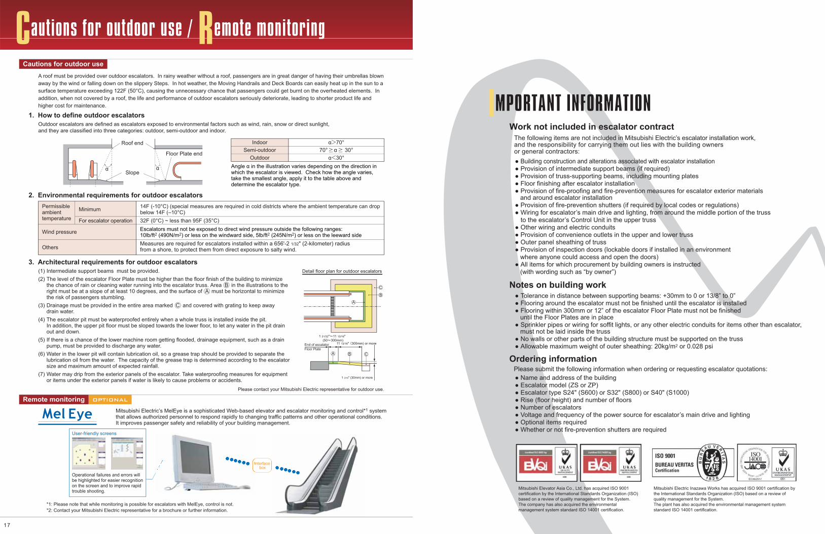
Cautions for outdoor use / Remote monitoring
Mitsubishi Electric’s MelEye is a sophisticated Web-based elevator and escalator monitoring and control*1 system that allows authorized personnel to respond rapidly to changing traffic patterns and other operational conditions. It improves passenger safety and reliability of your building management.
Please contact your Mitsubishi Electric representative for outdoor use.
*1: Please note that while monitoring is possible for escalators with MelEye, control is not.*2: Contact your Mitsubishi Electric representative for a brochure or further information.
User-friendly screens
Indoor α>70°
α<30°Semi-outdoor
Outdoor
2. Environmental requirements for outdoor escalators
Minimum
For escalator operation
Permissibleambient temperature
Wind pressure
Others
14F (-10°C) (special measures are required in cold districts where the ambient temperature can drop below 14F (–10°C)32F (0°C) ~ less than 95F (35°C)Escalators must not be exposed to direct wind pressure outside the following ranges:10lb/ft2 (490N/m2) or less on the windward side, 5lb/ft2 (245N/m2) or less on the leeward sideMeasures are required for escalators installed within a 656'-2 1/32" (2-kilometer) radius from a shore, to protect them from direct exposure to salty wind.
3. Architectural requirements for outdoor escalators
1. How to define outdoor escalators
Operational failures and errors will be highlighted for easier recognition on the screen and to improve rapid trouble shooting.
Intermediate support beams must be provided.The level of the escalator Floor Plate must be higher than the floor finish of the building to minimizethe chance of rain or cleaning water running into the escalator truss. Area B in the illustrations to theright must be at a slope of at least 10 degrees, and the surface of A must be horizontal to minimizethe risk of passengers stumbling.Drainage must be provided in the entire area marked C and covered with grating to keep awaydrain water.The escalator pit must be waterproofed entirely when a whole truss is installed inside the pit. In addition, the upper pit floor must be sloped towards the lower floor, to let any water in the pit drainout and down.If there is a chance of the lower machine room getting flooded, drainage equipment, such as a drainpump, must be provided to discharge any water. Water in the lower pit will contain lubrication oil, so a grease trap should be provided to separate thelubrication oil from the water. The capacity of the grease trap is determined according to the escalatorsize and maximum amount of expected rainfall.Water may drip from the exterior panels of the escalator. Take waterproofing measures for equipmentor items under the exterior panels if water is likely to cause problems or accidents.
(1)(2)
(3)
(4)
(5) (6)
(7)
Cautions for outdoor use
Remote monitoring
70° α 30°
Interfacebox
A roof must be provided over outdoor escalators. In rainy weather without a roof, passengers are in great danger of having their umbrellas blown away by the wind or falling down on the slippery Steps. In hot weather, the Moving Handrails and Deck Boards can easily heat up in the sun to a surface temperature exceeding 122F (50°C), causing the unnecessary chance that passengers could get burnt on the overheated elements. In addition, when not covered by a roof, the life and performance of outdoor escalators seriously deteriorate, leading to shorter product life and higher cost for maintenance.
Outdoor escalators are defined as escalators exposed to environmental factors such as wind, rain, snow or direct sunlight, and they are classified into three categories: outdoor, semi-outdoor and indoor.
Angle α in the illustration varies depending on the direction in which the escalator is viewed. Check how the angle varies, take the smallest angle, apply it to the table above and determine the escalator type.
OPTIONAL
Slope
Roof end
Floor Plate end
α α
Detail floor plan for outdoor escalators
11 13/16" 300mm) or more
1 31/32" 11 13/16"(50 300mm)
End of escalatorFloor Plate
1 3/16" (30mm) or more
A
A
B
B
C
C
17
Work not included in escalator contract
Notes on building work
Ordering information
IMPORTANT INFORMATION
● Name and address of the building● Escalator model (ZS or ZP)● Escalator type S24" (S600) or S32" (S800) or S40" (S1000)● Rise (floor height) and number of floors● Number of escalators● Voltage and frequency of the power source for escalator’s main drive and lighting● Optional items required ● Whether or not fire-prevention shutters are required
The following items are not included in Mitsubishi Electric’s escalator installation work, and the responsibility for carrying them out lies with the building ownersor general contractors:
Please submit the following information when ordering or requesting escalator quotations:
Mitsubishi Electric Inazawa Works has acquired ISO 9001 certification by the International Standards Organization (ISO) based on a review of quality management for the System.The plant has also acquired the environmental management system standard ISO 14001 certification.
● Tolerance in distance between supporting beams: +30mm to 0 or 13/8” to 0”● Flooring around the escalator must not be finished until the escalator is installed● Flooring within 300mm or 12” of the escalator Floor Plate must not be finished until the Floor Plates are in place● Sprinkler pipes or wiring for soffit lights, or any other electric conduits for items other than escalator, must not be laid inside the truss ● No walls or other parts of the building structure must be supported on the truss● Allowable maximum weight of outer sheathing: 20kg/m2 or 0.028 psi
● Building construction and alterations associated with escalator installation● Provision of intermediate support beams (if required)● Provision of truss-supporting beams, including mounting plates● Floor finishing after escalator installation● Provision of fire-proofing and fire-prevention measures for escalator exterior materials and around escalator installation● Provision of fire-prevention shutters (if required by local codes or regulations)● Wiring for escalator’s main drive and lighting, from around the middle portion of the truss to the escalator’s Control Unit in the upper truss● Other wiring and electric conduits ● Provision of convenience outlets in the upper and lower truss● Outer panel sheathing of truss● Provision of inspection doors (lockable doors if installed in an environment where anyone could access and open the doors)● All items for which procurement by building owners is instructed (with wording such as “by owner”)
Mitsubishi Elevator Asia Co., Ltd. has acquired ISO 9001 certification by the International Standards Organization (ISO) based on a review of quality management for the System.The company has also acquired the environmental management system standard ISO 14001 certification.