line post insulators ANSI - Sediver post insulators ANSI USA/Canada ... basic and minimum...
16
Sediver composite line post insulators ANSI USA/Canada 2010
Transcript of line post insulators ANSI - Sediver post insulators ANSI USA/Canada ... basic and minimum...
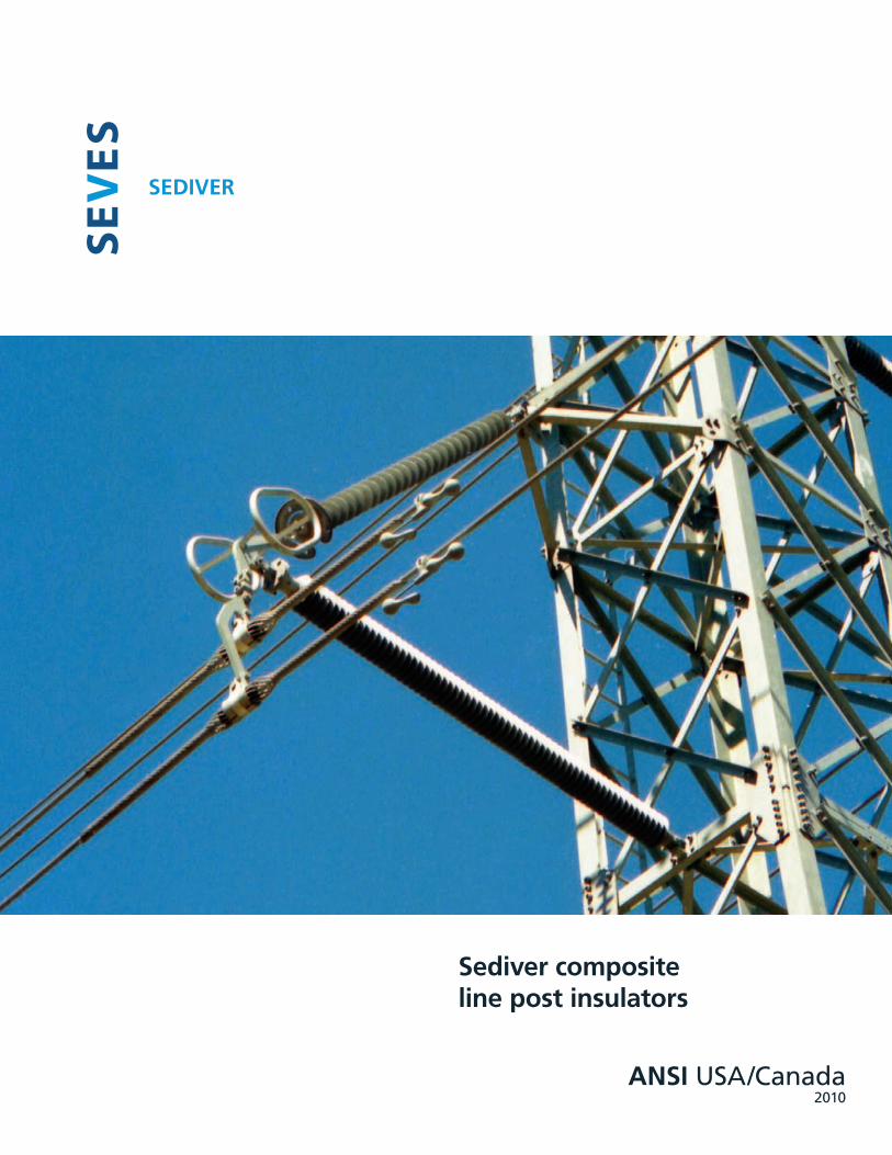
Sediver composite line post insulators
ANSI USA/Canada 2010

This catalog presents a selection of the Sediver composite Line Post insulators answering the needs of North-American customers in term of standards (ANSI), current practices and environmental conditions. ANSI standard C29.17 sets the basic and minimum requirements for this type of insulator. Sediver composite insulators meet and exceed the performance requirements of ANSI standards.
* Some of the companies above are now part of new entities
Sediver introduced composite insulators in 1975, after a 10-year research and development program. The dependability of the Sediver design has been demonstrated by the excellent performance of nearly 5 million polymer insulators now installed worldwide at voltages from 15 kV to 735 kV.
Experience records in the U.S. and world-wide confirm that Sediver composite insulators have proven to perform extremely well over the last 30 years.
Sediver composite insulators in North America
Alabama Electric Coop, Andalusia, AL - Alabama Power Co, Birmingham, AL - Appalachian Power Co, - Arizona Public Service Co, AZ - Austin (City of), Austin, TX - Baltimore Gas & Electric, Baltimore, MD - Big Rivers Electric, Henderson, KY - Bonneville Power Administration, Portland, OR - Carolina Power & Light, Raleigh, NC - Central Illinois Public Service, Springfield, IL - Central Power & Light, Corpus Christi, TX - Commonwealth Edison Co, IL - Connecticut Light & Power, CT - Delmarva Power & Light, Wilmington, DE - Delmarva Power Co, MD - Detroit Edison, Detroit, MI - Douglas Country PUD, Washington, WA - Empire Electric District, Joplin, MO - Florida Power & Light, Miami, FL - Georgia Power, Atlanta, GA - Grant County PUD - Houston Light & Power, Houston, TX - Idaho Power, Morristown, NJ - Imperial Irrigation District Iowa-Illinois Gas & Electric, IL - Jersey Central, Power & Light Morriston, NJ - Kansas City Power & Light, KS - Kansas City Public Utility Board, KS - Kansas Gas & Electricity, KS - Kansas Power & Light, KS - Knoxville Utilities Board, TN - Los Angeles Dept of Water & Power, Los Angeles, CA - Midway Sunset Co-Generation, CA - Minnkota Power Coop, Mississippi Power & Light, MS - Mississippi Power Co, MS - Nebraska Public Power District, Colombus, NB - Nevada Power Co, NV - New England Power Co - New York State Electric & Gas, NY - Niagara Mohawk Power Co, - North Virginia Electric Coop, VA - Northern Indiana Public Service, IN - Northern States Power Co, Ohio Edison Company, OH - Otter Tail Power Company, - Pacific Gas & Electric,- Pacific Power & Light, Portland, OR - Pensylvannia Power Co, Allentown, PA - Philadelphia Electric - Public Service Electric & Gas, Newark, NJ - Public Service of Colorado, Denver, CO - Public Service of Indiana, IN - Public Service of New Hampshire, NH - Public Service of New Mexico, NM - Public Service of Oklahoma, OK - Puget Sound Power & Light, - San Antonio {City of}, Public Serv, Bd, Tx San Diego Gas & Electric, Sierra Pacific Power Company, - South Carolina Electric & Gas, SC - South Mississippi Power Assoc, MS Southern California Edison, CA - Southwestern Electric Power Co, - Southwestern Public Service, Tacoma {City of}, Washington, WA - Tampa Electric, Tarheel Electric Membership Association, - Tennesse Valley Authority, Chattanooga, TN - Tri-State Generation & Trans, Ass, - Union Electric Co, St Louis, MO - United Power Association, Elk River, - Utah Power & Light, Salt Lake city, UT - West Penn Power, - Western Area Power Adminis, - Winfield {City of}, Kansas, KS - Wisconsin Electric Power, WI - Wisconsin Power & Light, WI - Wisconsin Public Service, WI - USA Alberta Power, BC Hydro, Enmax, Hydro Québec, Hydro One, Manitoba Hydro, Newfoundland Hydro, NB Power, Sask Power - Canada
Some customers* of Sediver composite insulators in the U.S.A and Canada
�

Sediver today
Today Sediver’s global presence is assured by: manufacturing facilities located in South America (Brazil), Europe (Italy) and the Far East (China). Each facility is ISO 9001-2000 certified and is governed by the same quality assurance programs and organization. This ensures that all Sediver insulators are manufactured with the same design, following the same methods and procedures in order to supply insulators to our worldwide clients with the same level of high quality.
centralized technical resources located in France, including Research and Development and Customer Technical Support as well as high voltage laboratories.
a large and widespread commercial network ensuring timely assistance to customers in the execution of their projects. The sales offices for North America are based in Tiffin (OH), USA and Montreal, Canada, with regional representatives covering all of the North American territory.
Quality driven organization and staff
Ideally, an insulator once installed, should be maintenance free and forgotten by the operator of the line for several decades. Sediver contributes to achieving this goal by placing quality at all levels of the organization and at the forefront of the actions undertaken by all personnel. The Sediver quality system covers all products and activities from the design, manufacturing, testing and supply, up to after-sales service.
Quality of products
Each factory quality organization is coordinated through a centralized Quality Department who acts as the client’s representative in determining and assuring full compliance of the manufactured insulators with the highest standards. Each quality department has absolute authority to ensure that the overall quality policy is enforced and respected at all levels of operations.
Quality of technical support
A team of skilled engineers operating in our Product Engineering Dept are dedicated to providing solutions to customers in the field of high-voltage insulation and protection. Their know how is based on 60 years of experience, testing and research carried out in state of the art laboratories using cutting edge technology in the fields of material science and mechanical and HV testing, including pollution testing and 3D electrical and mechanical simulations.
The SEVES group is a world leader in the power insulator industry, specialized in composite, toughened glass and porcelain insulators for high voltage transmission lines and substations.
Sediver is part of the Seves group and has been specialized for the last 60 years in the field of high voltage toughened glass and polymer insulation. More recently, composite surge arresters have been added to our product range.
�

�
Long term performanceThe direct injection molding process used by Sediver offers a unique quality of interface between the rod and the housing as well as between the end fitting and the housing. Making the insulator fully “impenetrable”, this feature also offers unparallel quality of bonding along the rod preventing any risk of internal tracking along the longitudinal interface of the composite insulator.
Sediver unique combination between design features ... and manufacturing process
Sediver « Impenetrable » design proven dependability
Injected housing moulded directly to the rod and the fittings forming an impenetrable protective housing
End fitting attached to rod by compression crimping process which is acoustically monitored to ensure consistent performance
Bonded interface between rubber and metal fitting - no seals
All Sediver composite insulators are manufactured at high pressure and high temperature thanks to direct injection molding technology. This unique “impenetrable” housing design safely protects the fiberglass rod against water or contaminant penetration without the need of any “seals”. Injection molding technology has been adopted and continuously perfected by Sediver since 1985.
The Sediver state-of-the-art insulator is made with the most advanced materials, resulting from extensive research testing and field experience gained over more than 50 years of expertise in overhead line insulation.
Field experience has clearly demonstrated that composite insulator's performance and degradation is directly related to some key design features. One of them, (provided material selection is adequate),
is defined by the method of construction of the housing. In this regard, internal tracking and moisture penetration are known to be the main actors for failures in service. To prevent such risks, Sediver's housing is directly injected at high temperature and high pressure on the fiberglass rod and the fittings, assuring a complete adherence and strong bonding of the rubber.
The perfect bonding between rod and housing will not allow any development of internal tracking under the housing. The complete adherence of the rubber on to the end fitting enlarged collar eliminates the need for inherently weak sealing devices responsible for moisture ingress, and subsequently brittle fractures. The housing being totally “impenetrable” will also prevent possible moisture penetration along the core.
Mechanical ratings and definitions
Sediver line post insulators are available with core diameter of 1.75" to 3.5". Applications curves taking into account tri-dimensional loading are available upon request.
Specified Cantilever Load (SCL): cantilever load rating when tested in accordance with ANSI C29.17-2002.
Specified Tensile Load (STL): tensile load rating when tested in accordance with ANSI C29.17-2002.
Maximum Design Cantilever Load (MDCL): maximum cantilever load which causes no damage on the insulator. It is set at 50% of SCL.

�
Interface integrity monitoringThe longitudinal interface along the fiberglass rod and the rubber housing is highly critical in regard to risks of internal tracking if this interface is not perfectly bonded.
Thanks to the injection molding process, the Sediver design offers the strongest possible bonding and adherence between these two components.
Additionally, Sediver designed an exclusive non destructive testing method based on ultrasonic techniques to validate, on a sampling basis, the quality of this interface.
This control performed on finished products ensures the highest level of dependability of our polymer insulators.
Sediver unique combination between design features ... and manufacturing process
Fiberglass reinforced epoxy resin rod
Galvanized end fittings designed to reduced the E-field and provide a large surface rubber bonding
Housing material
Sediver line post insulators are available either with EPDM or with silicone rubber housing.
• EPDM compound has been specially formulated to provide optimum weathering and electrical properties for all operating conditions. Sediver has more than 30 years of excellent field experience with EPDM insulators over a wide range of pollution levels.
• Silicone compound provides excellent hydrophobic and recovery characteristics which limit leakage current and arcing in polluted or seacoast environments.
Both Sediver rubber formulations are the result of extensive research and testing programs.
Core: pultruded rods made by impregnation of high quality fiberglass with epoxy resin.
End fittings: hot dip galvanized steel, ductile or malleable cast iron for applications under severe environmental conditions.
Bases: hot deep galvanized rolled steel for bendable bases and ductile or malleable cast iron or steel for rigid bases.
Grading rings: • high grade aluminum alloy for the ring • hot dip galvanized steel for the bracket and supporting horn • stainless steel for bolts and nuts
Grading rings At higher operating voltages, grading rings are necessary to reduce the voltage gradient on and within the insulator, and to reduce radio noise to acceptable levels. As on ceramic strings, the need for grading rings also depends on admissible hardware design, conductor bundle position, altitude and contamination conditions. General recommendations for Sediver line post insulators used in non-contaminated and low altitude (<3000’) areas are:
Line voltage
Recommendations
2.5" serie 30
3.0" & 3.5" series 35 & 40
Line end Tower end Line end Tower end
230 kV X(1)
345 kV X X
500 kV X X X X
(1) No grading ring required for braced line post
Materials
Grading ring diameter 15.4" (390 mm)

Sediver composite line post insulators
�
1.7�” (��mm)SERIES �0
BaseA B C D
In mm In mm In mm In mm
GB-12 9.5 241 12 305 - - 0.94 23.8
VB-08 5 127 3 76 13.1 333 0.69 17.5
Trunnion clamps
Catalog N° Conductor range (inches)
ACTS 45-25-57 0.25-0.57
ACTS 45-5-106 0.50-1.06
ACTS 106-150 1.00-1.50
Mounting studs
StudRef.
A B C
In mm In mm In mm
SS-1 1.8 46 1.56 40 0.75 19
SS-2 2.0 51 1.56 40 0.88 22
SW-1 7.56 192 4.0 102 0.75 19
SW-2 8.07 205 4.0 102 0.88 22
for round poles 7" to 10" (178 to 254 mm)
End fittings
*to be used with trunnion clamps as per ANSI C29.7
Bases type GHorizontal Gain
GB-12Vertical Gain
V8-08
Line end
Pole end
K* V*
P
(20.6mm)Ø13/16"
3/4"- 10UNCor7/8"- 9UNC
3.3"(85mm)
0.77" MAX (19.5mm)
Ø 0.97" MIN (24.6mm)
BA
Slot 0.81"x 3.3" (20.6 x 84mm)
D
B
A
C
Slot 0.69"x 1.08" (17.5mm x 27.5mm)
Ø D
Ø DB
A
C
A
C
B
T

1.7�”(��mm)SERIES �0
Rev 8-10
Sediver composite line post insulators
7
Typical Line
Voltage
SediverCatalog
Designation
Number of
Sheds
Line Post Spacing
“X”
Leakage Distance
Dry Arcing Distance*
Low Frequency Flashover *
Critical Impulse
Flashover *
Max. Design Cantilever
Load
Approx. Net Wt Stud
Ref.Inches (mm)
Inches (mm)
Inches (mm)
Dry kV
Wet kV
Pos. kV
Neg. kV
Lbs (kN)
Lbs. (kg)
�� kV
SEDNPVN20 XH9 008 S0
8
20.6 37.9 14.3165 120 255 395
1450 11
SS-1or
SW-1
3/4"
522 962 363 6.5 5
SEDNPKN20 XH9 008 S020.6 37.9 14.3
165 120 255 3951450 11
522 962 363 6.5 5
SEDNPKG20 XH9 008 S022.0 37.9 14.3
165 120 255 3951360 19
558 962 363 6 8.6
SEDNPVN20 XH9 009 S0
9
22.0 42.7 15.8180 135 275 425
1350 12560 1085 401 6 5.3
SEDNPKN20 XH9 009 S022.0 42.7 15.8
180 135 275 4251350 12
560 1085 401 6 5.3
SEDNPKG20 XH9 009 S023.5 42.7 15.8
180 135 275 4251270 19
596 1085 401 5.7 8.8
�9 kV
SEDNPVN20 XH9 011 S0
11
25.1 52.4 18.8210 160 315 490
1190 13
SS-2or
SW-2
7/8"
637 1331 478 5.3 5.8
SEDNPKN20 XH9 011 S025.1 52.4 18.8
210 160 315 4901190 13
637 1331 478 5.3 5.8
SEDNPKG20 XH9 011 S026.5 52.4 18.8
210 160 315 4901130 21
673 1331 478 5 9.4
SEDNPVN20 XH9 012 S0
12
26.6 57.2 20.4225 175 335 515
1120 13676 1453 517 5 6.1
SEDNPKN20 XH9 012 S026.6 57.2 20.4
225 175 335 5151120 13
676 1453 517 5 6.1
SEDNPKG20 XH9 012 S028.0 57.2 20.4
225 175 335 5151070 21
711 1453 517 4.8 9.6
SEDNPVN20 XH9 013 S0
13
28.1 62.0 21.9240 190 355 545
1060 14714 1576 555 4.7 6.4
SEDNPKN20 XH9 013 S028.1 62.0 21.9
240 190 355 5451060 14
714 1576 555 4.7 6.4
SEDNPKG20 XH9 013 S029.5 62.0 21.9
240 190 355 5451010 22
750 1576 555 4.5 9.9
88 kV
SEDNPVN20 XH9 015 S0
15
31.1 71.7 24.9265 215 395 590
960 15791 1822 632 4.3 6.9
SEDNPKN20 XH9 015 S031.1 71.7 24.9
265 215 395 590960 15
791 1822 632 4.3 6.9
SEDNPKG20 XH9 015 S032.5 71.7 24.9
265 215 395 590920 23
826 1822 632 4.1 10.5
SEDNPVN20 XH9 016 S0
16
32.7 76.5 26.4280 230 435 605
910 16830 1944 671 4.1 7.2
SEDNPKN20 XH9 016 S032.7 76.5 26.4
280 230 435 605910 16
830 1944 671 4.1 7.2
SEDNPKG20 XH9 016 S034.1 76.5 26.4
280 230 435 605880 24
865 1944 671 3.9 10.7
Tests complying with ANSI C29.17. Table shows typical models. Other dimensions or fittings combinations are available on request. STL: Clamp top 5,000 Lbs (22 kN) - Tongue 10,000 Lbs (44 kN)
5°
x
NPKG20
x
NPVN20
ØØ
x
5.78"( 147 mm)
1.5"
(38.5mm)
NPKN20
Sediver designation systemSED N P1 K2 G3 20 XH9 012 S 0
Sediverdesign
ANSIStandard
End fitting and base Core size series Shed profile
Number of sheds
Housing material Number of grading rings1-Pole end 2-Line end S - Silicone
3-Base type: G-Gain, N-No base E - EPDM
A B
C
5XD1
1XD2
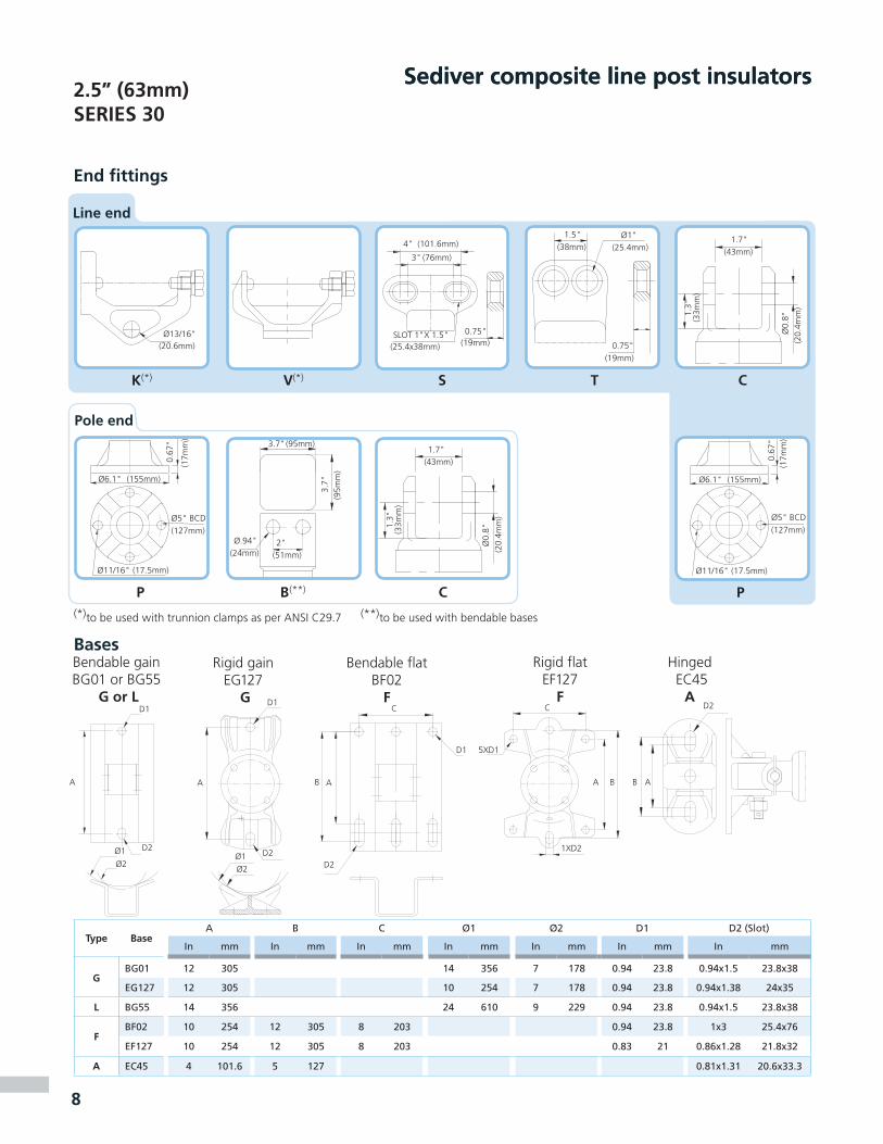
8
Sediver composite line post insulators�.�” (��mm)SERIES �0
End fittings
Sediver composite line post insulators
BasesBendable gainBG01 or BG55
G or L
Bendable flat BF02
F
Rigid gainEG127
G
Rigid flatEF127
F
Hinged EC45
A
Type BaseA B C Ø1 Ø2 D1 D2 (Slot)
In mm In mm In mm In mm In mm In mm In mm
GBG01 12 305 14 356 7 178 0.94 23.8 0.94x1.5 23.8x38
EG127 12 305 10 254 7 178 0.94 23.8 0.94x1.38 24x35
L BG55 14 356 24 610 9 229 0.94 23.8 0.94x1.5 23.8x38
FBF02 10 254 12 305 8 203 0.94 23.8 1x3 25.4x76
EF127 10 254 12 305 8 203 0.83 21 0.86x1.28 21.8x32
A EC45 4 101.6 5 127 0.81x1.31 20.6x33.3
(*)to be used with trunnion clamps as per ANSI C29.7 (**)to be used with bendable bases
D1
D2Ø1
Ø2
A
D2
B A
D1
CD1
D2
Ø2Ø1
A B A
D2
Line end
P
Pole end
B(**) C
(43mm)1.7"
(33m
m)
1.3"
(20.
4mm
)Ø
0.8"
(95mm)3.7"
(51mm)2"
(95m
m)
3.7"
(24mm)Ø.94"
(155mm)Ø6.1"
(17.5mm)Ø11/16"
(17m
m)
0.67
"
(127mm)Ø5" BCD
P
(155mm)Ø6.1"
(17.5mm)Ø11/16"
(127mm)Ø5" BCD
(17m
m)
0.67
"
(101.6mm)4"
(76mm)3"
(20.6mm)Ø13/16" SLOT 1"X 1.5"
(25.4x38mm) (19mm)0.75"
(25.4mm)Ø1"
(19mm)0.75"
(43mm)1.7"
(33m
m)
1.3"
(20.
4mm
)Ø
0.8"
V(*) TSK(*) C
(38mm)1.5"
9
�.�”(��mm)SERIES �0
Sediver composite line post insulators
Typical Line
Voltage
SediverCatalog
Designation
Number of
Sheds
Line Post Spacing
“X”
Leakage Distance
Dry Arcing Distance*
Low Frequency Flashover *
Critical Impulse
Flashover *
Max. Design Cantilever
Load
Approx. Net Wt
Inches (mm)
Inches (mm)
Inches (mm)
Dry kV
Wet kV
Pos. kV
Neg. kV
Lbs (kN)
Lbs. (kg)
�9 kV
SEDNBSG30XH 016 S0 1634.3 77 25.8
275 225 425 5952630 56
871 1958 657 11.7 25.6
SEDNBSG30XH 019 S0 1938.7 92 30.4
320 265 495 6702260 60
984 2331 772 10.1 27.1
�9-11� kV SEDNBSG30XH 023 S0 2344.6 111 36.5
375 315 585 7601900 64
1134 2829 926 8.5 29.0
11� kV SEDNBSG30XH 025 S0 2547.6 121 39.5
400 335 635 8001770 66
1210 3078 1003 7.9 30.0
11�-1�8 kV
SEDNBSG30XH 029 S0 2953.5 141 45.6
455 385 725 8851540 71
1360 3575 1157 6.8 32.0
1�8 kV SEDNBSG30XH 034 S0 3461.0 165 53.1
520 445 835 9851330 76
1549 4198 1350 5.9 34.5
1�1 kV
SEDNBSG30XH 039 S0 3968.4 190 60.7
585 500 950 10801170 82
1737 4820 1542 5.2 37.0
SEDNBSG30XH 043 S0 4374.3 209 66.8
635 545 1040 11551070 86
1887 5318 1696 4.8 39.0
with
grad
ing
ring
* ��0 kV
SEDNBSG30XH 047 S1 4780.2 229 68.4
645 555 1060 1175990 96
2038 5815 1737 4.4 43.4
SEDNBSG30XH 051 S1 5186.2 249 74.4
695 600 1150 1245920 100
2189 6313 1891 4.1 45.4
SEDNBSG30XH 055 S1 5592.1 268 80.5
745 640 1240 1315850 104
2339 6811 2045 3.8 47.3
SEDNBSG30XH 058 S1 5896.5 283 85.0
785 670 1305 1370810 108
2452 7184 2160 3.6 48.8
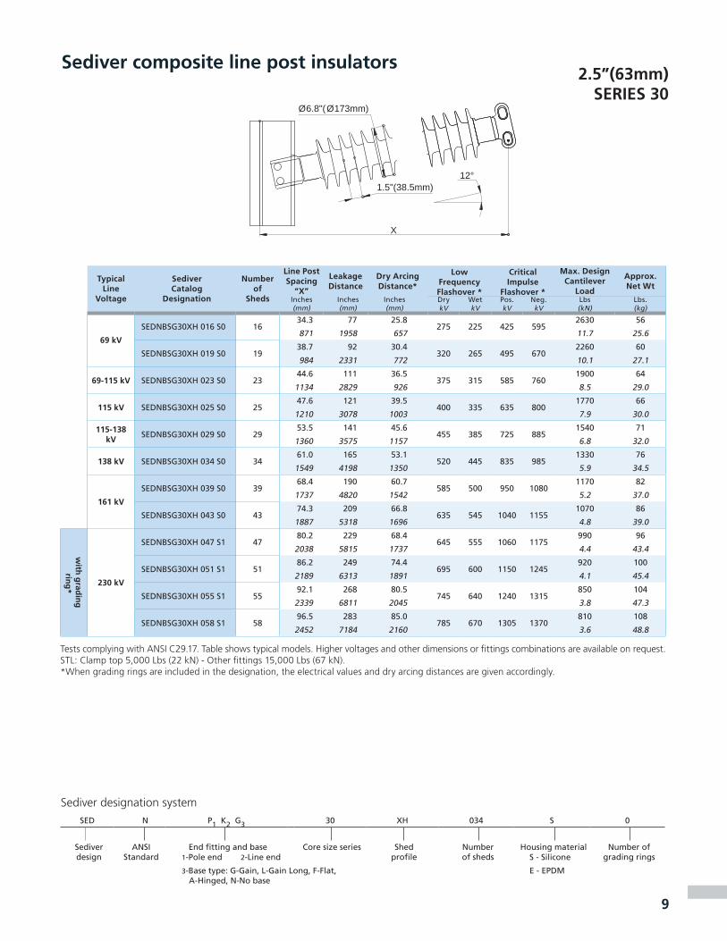
Tests complying with ANSI C29.17. Table shows typical models. Higher voltages and other dimensions or fittings combinations are available on request. STL: Clamp top 5,000 Lbs (22 kN) - Other fittings 15,000 Lbs (67 kN).*When grading rings are included in the designation, the electrical values and dry arcing distances are given accordingly.
Sediver designation system
12°
X
Ø6.8"(Ø173mm)
1.5"(38.5mm)
SED N P1 K2 G3 30 XH 034 S 0
Sediverdesign
ANSIStandard
End fitting and base Core size series Shed profile
Number of sheds
Housing material Number of grading rings1-Pole end 2-Line end S - Silicone
3-Base type: G-Gain, L-Gain Long, F-Flat, A-Hinged, N-No base
E - EPDM
10
Sediver composite line post insulators�.0”(7� mm)SERIES ��
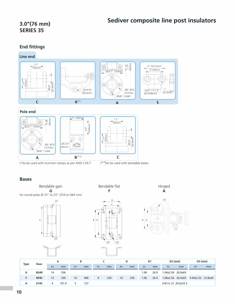
End fittings
Type BaseA B C D D1 D� (slot) D� (slot)
In mm In mm In mm In mm In mm In mm In mm
G BG�0 14 356 1.06 26.9 1.06x2.56 26.9x65
F BF�0 13 330 16 406 9 229 10 254 1.06 26.9 1.06x2.56 26.9x65 0.94x2.52 23.8x64
A EC�� 4 101.6 5 127 0.81x1.31 20.6x33.3
(*)to be used with trunnion clamps as per ANSI C29.7 (**)to be used with bendable bases
Bases
Bendable gain G
for round poles Ø 10" to 23" (254 to 584 mm)
D1
D2
A
HingedA
B A
D2
Line end
4" (101.6mm)
3"(76mm)
SLOT 1"X 1.5"(25.4x38mm) (25.4mm)
1"
S
(20.6mm)Ø13/16"
K(*)
Pole end
B(**) C
5.5" (140mm)
(75mm)2.95"
(140
mm
)5.
5"
(35mm)Ø1.37"
Bendable flatF
B A
D2
D1
D
C
D3
(43mm)1.7"
(33m
m)
1.3"
(20.
4mm
)Ø
0.8"
(43mm)1.7"
(33m
m)
1.3"
(20.
4mm
)Ø
0.8"
A
C
(Ø 6.7" 170mm)
(45m
m)
1.77
"
(127mm)Ø5" BCD
Ø5/8" 11UNC
A
(Ø 6.7" 170mm)
(45m
m)
1.77
"
(127mm)Ø5" BCD
Ø5/8" 11UNC

�.0”(7� mm)SERIES ��
Sediver composite line post insulators
Typical Line
Voltage
SediverCatalog
Designation
Number of
Sheds
Line Post Spacing
“X”
Leakage Distance
Dry Arcing Distance*
Low Frequency Flashover *
Critical Impulse
Flashover *
Maximum Design
Cantilever Load
Approx. Net Wt
Inches (mm)
Inches (mm)
Inches (mm)
Dry kV
Wet kV
Pos. kV
Neg. kV
Lbs (kN)
Lbs. (kg)
�9/11� kV SEDNBSG35 XI 021 S0 2145.2 99 33.3
345 285 540 7102920 56
1148 2518 846 13 25.2
11� kV SEDNBSG35 XI 023 S0 2348.2 108 36.3
370 310 585 7552740 58
1224 2756 923 12.2 26.4
11�/1�8 kV SEDNBSG35 XI 027 S0 2754.1 127 42.4
425 360 675 8402430 63
1374 3232 1077 10.8 28.7
1�8 kV SEDNBSG35 XI 032 S0 3261.5 151 50.0
490 420 790 9452140 70
1563 3827 1270 9.5 31.7
1�1 kV
SEDNBSG35 XI 037 S0 3768.9 174 57.6
555 475 905 10401910 76
1751 4422 1462 8.5 34.6
SEDNBSG35 XI0 41 S0 4174.9 193 63.6
605 520 995 11201760 81
1902 4898 1616 7.8 36.9
��0 kV
SEDNBSG35 XI 044 S0 4479.3 207 68.2
645 555 1060 11751660 85
2015 5255 1732 7.4 38.6
SEDNBSG35 XI 048 S0 4885.2 226 74.2
695 595 1150 12451550 90
2165 5731 1886 6.9 41.0
SEDNBSG35 XI 052 S0 5291.2 244 80.3
745 640 1235 13151450 95
2316 6207 2040 6.4 43.3
SEDNBSG35 XI 055 S0 5595.6 258 84.8
780 670 1300 13651380 99
2429 6564 2155 6.1 45.1
SEDNBSG35 XI 058 S0 58100.1 272 89.4
820 700 1370 14151330 103
2542 6921 2271 5.9 46.8
Tests complying with ANSI C29.17. Table shows typical models. Higher voltages and other dimensions or fittings combinations are available on request. STL: Clamp top 5,000 Lbs (22 kN) - Other fittings 15,000 Lbs (67 kN).*When grading rings are included in the designation, the electrical values and dry arcing distances are given accordingly.
11
12°
X
Ø6.9"(Ø176mm)
1.5"(38.5mm)
Sediver designation system
SED N P1 K2 G3 35 XI 032 S 0
Sediverdesign
ANSIStandard
End fitting and base Core size series Shed profile
Number of sheds
Housing material Number of grading rings1-Pole end S - Silicone
2-Line end 3-Base type: G-Gain, F-Flat, A-Hinged, N-No base
E - EPDM

Sediver composite line post insulators�.�”(88 mm)SERIES �0
1�
End fittings
Type BaseA B C D D1 D� (slot) D� (slot)
In mm In mm In mm In mm In mm In mm In mm
G BG�0 14 356 1.06 26.9 1.06x2.56 26.9x65
F BF�0 13 330 16 406 9 229 10 254 1.06 26.9 1.06x2.56 26.9x65 0.94x2.52 23.8x64
A EC�� 4 101.6 5 127 0.81x1.31 20.6x33.3
(*)to be used with trunnion clamps as per ANSI C29.7 (**)to be used with bendable bases
Bases
Bendable gain G
for round poles Ø 10" to 30" (254 to 762 mm)
D1
D2
A
HingedA
B A
D2
Line end
4" (101.6mm)
3"(76mm)
SLOT 1"X 1.5"(25.4x38mm) (25.4mm)
1"
S
(20.6mm)Ø13/16"
K(*)
Pole end
B(**) C
5.5" (140mm)
(75mm)2.95"
(140
mm
)5.
5"
(35mm)Ø1.37"
Bendable flatF
B A
D2
D1
D
C
D3
(43mm)1.7"
(33m
m)
1.3"
(20.
4mm
)Ø
0.8"
(43mm)1.7"
(33m
m)
1.3"
(20.
4mm
)Ø
0.8"
A
C
(Ø 6.7" 170mm)
(45m
m)
1.77
"
(127mm)Ø5" BCD
Ø5/8" 11UNC
A
(Ø 6.7" 170mm)
(45m
m)
1.77
"
(127mm)Ø5" BCD
Ø5/8" 11UNC
1�
�.�”(88 mm)SERIES �0
Sediver composite line post insulators
Typical Line
Voltage
SediverCatalog
Designation
Number of
Sheds
Line Post Spacing
“X”
Leakage Distance
Dry Arcing Distance*
Low Frequency Flashover *
Critical Impulse
Flashover *
Max. Design Cantilever
Load
Approx. Net Wt
Inches (mm)
Inches (mm)
Inches (mm)
Dry kV
Wet kV
Pos. kV
Neg. kV
Lbs (kN)
Lbs. (kg)
11� kV SEDNBSG40XV023S0 2348.1 96 36.4
370 310 585 7554110 110
1221 2428 925 18.3 50
11�-1�8 kV SEDNBSG40XV027S0 2754.0 112 42.5
425 360 680 8453660 116
1371 2852 1079 16.3 52.8
1�8 kV SEDNBSG40XV032S0 3261.4 133 50.1
490 420 790 9453230 124
1560 3382 1272 14.4 56.4
1�1 kV
SEDNBSG40XV037S0 3768.8 154 57.6
555 475 905 10452890 132
1748 3912 1464 12.8 60
SEDNBSG40XV041S0 4174.8 171 63.7
610 520 995 11202620 139
1900 4336 1618 11.6 62.9
��0 kV
SEDNBSG40XV045S0 4580.7 187 69.8
660 565 1085 11902410 145
2049 4760 1772 10.7 65.7
SEDNBSG40XV049S0 4986.6 204 75.8
710 610 1170 12652220 151
2200 5183 1926 9.9 68.6
SEDNBSG40XV056S0 5697 233 86.4
795 680 1325 13851960 162
2463 5925 2196 8.8 73.6
with
grad
ing
rin
g*
��� kV SEDNBSG40XV069S1 69116.3 288 104.6
940 800 1580 15801660 188
2953 7303 2657 7.4 85.4
�00 kV SEDNBSG40XV085S2 85140.0 354 121.8
1075 915 1760 17601420 219
3556 8998 3094 6.3 99.3
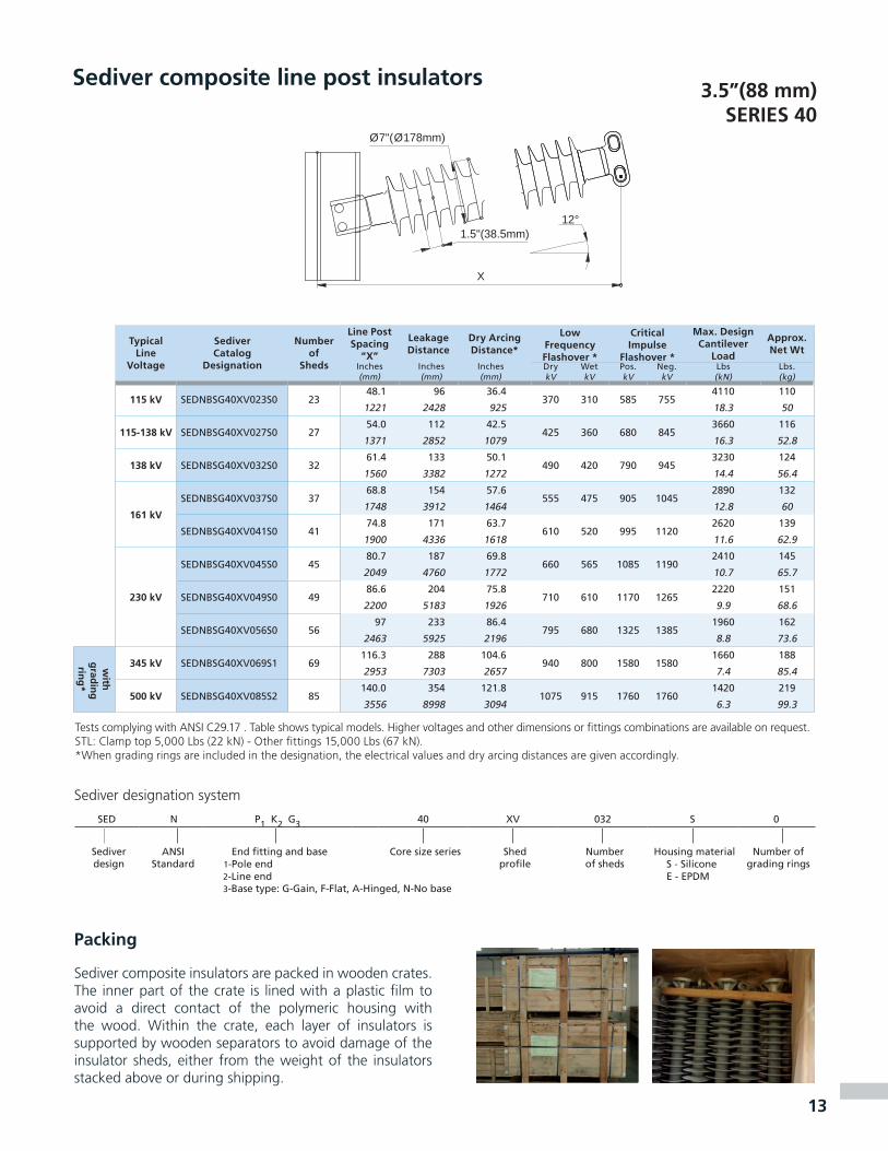
Tests complying with ANSI C29.17 . Table shows typical models. Higher voltages and other dimensions or fittings combinations are available on request. STL: Clamp top 5,000 Lbs (22 kN) - Other fittings 15,000 Lbs (67 kN).*When grading rings are included in the designation, the electrical values and dry arcing distances are given accordingly.
Sediver designation system
12°
X
Ø7"(Ø178mm)
1.5"(38.5mm)
Packing
Sediver composite insulators are packed in wooden crates. The inner part of the crate is lined with a plastic film to avoid a direct contact of the polymeric housing with the wood. Within the crate, each layer of insulators is supported by wooden separators to avoid damage of the insulator sheds, either from the weight of the insulators stacked above or during shipping.
SED N P1 K2 G3 40 XV 032 S 0
Sediverdesign
ANSIStandard
End fitting and base Core size series Shed profile
Number of sheds
Housing material Number of grading rings1-Pole end S - Silicone
2-Line end 3-Base type: G-Gain, F-Flat, A-Hinged, N-No base
E - EPDM
1�
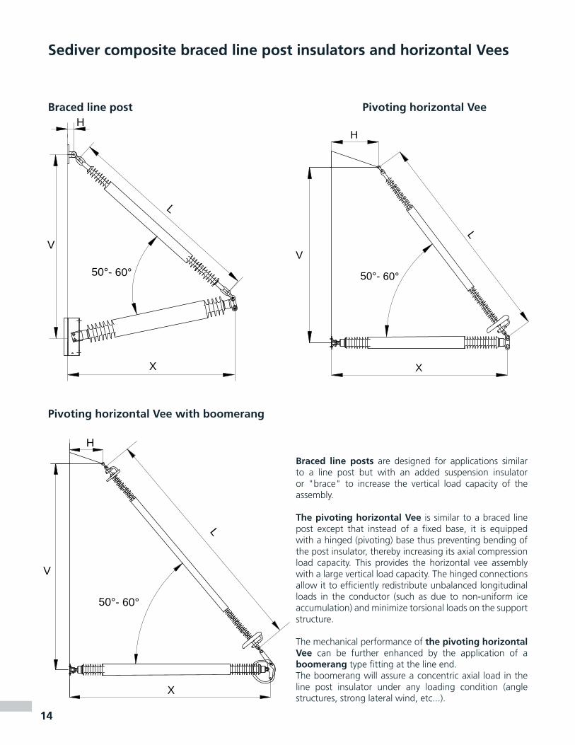
Sediver composite braced line post insulators and horizontal Vees
Braced line post Pivoting horizontal Vee
Pivoting horizontal Vee with boomerang
Braced line posts are designed for applications similar to a line post but with an added suspension insulator or "brace" to increase the vertical load capacity of the assembly.
The pivoting horizontal Vee is similar to a braced line post except that instead of a fixed base, it is equipped with a hinged (pivoting) base thus preventing bending of the post insulator, thereby increasing its axial compression load capacity. This provides the horizontal vee assembly with a large vertical load capacity. The hinged connections allow it to efficiently redistribute unbalanced longitudinal loads in the conductor (such as due to non-uniform ice accumulation) and minimize torsional loads on the support structure.
The mechanical performance of the pivoting horizontal Vee can be further enhanced by the application of a boomerang type fitting at the line end. The boomerang will assure a concentric axial load in the line post insulator under any loading condition (angle structures, strong lateral wind, etc...).
L
X
H
V
50°- 60°
L
X
H
V
50°- 60°
X
L
H
V
50°- 60°

1�
Sediver composite braced line post insulators and horizontal Vees
Typical Line
Voltage
SediverCatalog
Designation
Line PostDesignation
BraceDesignation
X L V HLow
Frequency Flashover *
Critical Impulse
Flashover *
Maximum Vertical Load(1)
Approx. Net Wt
Inmm
Inmm
Inmm
Inmm
Dry kV
Wet kV
Pos. kV
Neg. kV
Lbs (kN)
Lbs. (kg)
with
grad
ing
ring
*
1�1 kVPHVF 161 3014 0001 S1 NCSA30XH39S0 NEE120XF057S1
70.3 73.4 68.7 22510 435 820 970
11250 801786 1865 1744 559 50 36
PHVF 161 3014 0002 S1 NCSA30XH43S0 NEE120XF063S176.4 79.9 72.2 22
555 475 900 104011250 85
1940 2030 1835 559 50 39
��0 kV
PHVF 230 3014 0001 S1 NCSA30XH47S0 NEE120XF069S182.4 86.4 80.2 28
610 525 1000 112511250 90
2094 2195 2038 711 50 41
PHVF 230 3014 0002 S1 NCSA30XH51S0 NEE120XF075S188.5 92.9 83.9 28
660 570 1085 119511250 95
2248 2360 2130 711 50 43
PHVF 230 3014 0003 S1 NCSA30XH55S0 NEE120XF079S194.6 97.2 86.2 30
705 605 1170 126011250 100
2402 2470 2190 762 50 45
PHVF 230 3014 0004 S1 NCSA30XH58S0 NEE120XF083S199.1 101.6 88.2 30
745 640 1235 131511250 104
2517 2580 2240 762 50 47
Pivoting horizontal Vee with boomerang
Typical Line
Voltage
SediverCatalog
Designation
Line PostDesignation
BraceDesignation
X L V HLow
Frequency Flashover *
Critical Impulse
Flashover *
Maximum Vertical Load(1)
Approx. Net Wt
Inmm
Inmm
Inmm
Inmm
Dry kV
Wet kV
Pos. kV
Neg. kV
Lbs (kN)
Lbs. (kg)
with
grad
ing
ring
*
��� kV PHVB 345 3014 0001 S2 NCCA30XH69S0 NEE120XF097S1115.9 116.7 108.8 32
835 715 1400 144010125 161
2945 2965 2765 813 45 73
�00 kV PHVB 500 4014 0002 S4 NCCA40XV85S1 NEE180XF119S5141.8 141.7 134 50
1020 870 1730 169011250 251
3600 3598 3402 1270 50 114
Typical Line
Voltage
SediverCatalog
Designation
Line PostDesignation
BraceDesignation
X L V HLow
Frequency Flashover*
Critical Impulse
Flashover *
Maximum Vertical Load (1)
Approx. Net Wt
Inmm
Inmm
Inmm
Inmm
Dry kV
Wet kV
Pos. kV
Neg. kV
Lbs (kN)
Lbs. (kg)
11� kVBLPG 115 3014 0001 S0 NBSG30XH25S0 NEE120XF039S0
47.6 53.9 55.7 2400 335 635 800
11250 801209 1370 1416 51 50 36
BLPG 115 3014 0002 S0 NBSG30XH29S0 NEE120XF045S053,5 60.4 60.1 2
455 385 725 88011250 86
1361 1535 1528 51 50 39
1�8 kV BLPG 138 3014 0001 S0 NBSG30XH34S0 NEE120XF055S061.0 71.2 68.9 2
520 445 835 9809000 92
1549 1809 1750 51 40 42
with
grad
ing
ring
*
1�1 kVBLPG 161 3014 0001 S1 NBSG30XH39S0 NEE120XF065S1
68.4 82.1 79.2 2505 430 810 960
6750 106
1737 2085 2010 51 30 48
BLPG 161 3014 0002 S1 NBSG30XH43S0 NEE120XF071S174.3 88.6 83.6 2
555 475 900 10405625 111
1887 2250 2123 51 25 50
��0 kVBLPG 230 3014 0001 S1 NBSG30XH51S0 NEE120XF085S1
86.2 103.7 95.5 2655 560 1075 1185
4050 1222189 2634 2426 51 18 55
BLPG 230 3014 0002 S1 NBSG30XH55S0 NEE120XF091S192.1 110.2 99.9 2
690 590 1140 12403375 127
2339 2799 2538 51 15 58
Braced line post
Pivoting horizontal Vee
All assemblies above are equipped with two straight shackles, one at the tower end and one connecting the brace to the line post.Adjustable extension links or turnbuckles can be offered upon request in order to match different vertical distances on the tower as well as customized design.
Test complying with ANSI C29.17 . Table shows typical models. Other dimension of fittings combinations are available upon request.(*) When grading rings are included in the designation, the electrical values are given accordingly. (1) Maximum vertical load: with no longitudal or transversal stresses. Application curves taking into account tridimensional loading are available upon request.
Ø0.79"Ø(20mm)
4.45" (113mm)
0.94"(24mm)

Contribution to international committees
Since the very beginning of international technical cooperation, Sediver has always been an active member in fields of research and standardization in international committees and working groups dealing with all aspects of high voltage insulation; for example Sediver experts are Project Leaders in IEC working groups 36WG11, 36BMT10...
Institute of Electrical and Electronics Engineers
Sediver’s experts are
active in
• T&D Committee • WG Insulator
contamination
• WG Insulator strength
• WG Application of non ceramic insulators
• ESMOL
List of some IEEE and international publications on composite:“IEEE Guide for Braced Insulator Assemblies for Overhead Transmission Lines 60 kV and greater” IEEE TF1�.09.09.07 (E. DEL BELLO…) IEEE Transactions on Power Delivery, Vol.23 N°2, April 2008 p.785-791
«Determination of the brittle fracture process of field failed HV insulators» C. de TOURREIL ; G. THEVENET ; E. BROCARD ; N. SIAMPIRINGUE ; N. PICHON – XIVth ISH , 2005 Paper D-28
«Use of corona rings to control the electrical field along transmission line composite insulators» CIGRE WG B�-0� (E. BROCARD …) CIGRE TECHNICAL BROCHURE, 2005 N° 284
«Guide for the evaluation of composite line post insulators subjected to combined mechanical load / Guide pour l’évaluation des consoles isolantes composites soumises à une combinaison de charges mécaniques « CIGRE WG ��-0� (E. BROCARD…) ELECTRA, 2002, N° 203
«Composite Insulator Handling guide» CIGRE WG ��-0� (E. BROCARD …) CIGRE TECHNICAL BROCHURE, April 2001, N° 184
«Brittle fracture» of composite insulators : the new explanation and a field case study» C. DE TOURREIL, L. PARGAMIN, G.THEVENET, S. PRAT, N. SIAMPIRINGUE , ISH, 2001, Paper 5-25
«New compact composite insulation for environmental economic and safety considerations»D. DUMORA, 2001 WORLD INSULATOR CONGRESS AND EXHIBITION, Shanghai Nov. 18-21, 2001
«Non destructive techniques for the evaluation of the integrity of composite insulators» J.M. GEORGE, INTERNATIONAL SYMPOSIUM ON MODERN INSULATOR TECHNOLOGIES, Coral Gables Florida, Nov. 16-19, 1997
«Studies of the long term performance of composite insulators and of the representativity of ageing tests» G. RIQUEL, JM FOURMIGUE, D. DE DECKER, R. JOULIE, R. PARRAUD, CIGRE 1996, Paper 33-304
«Review of in service diagnostic testing of composite insulators / Revue des techniques de diagnostic en service pour isolateurs composites» CIGRE WG ��-0�, ELECTRA, 1996, N° 169
«Rating of composite suspension insulators related to the long term mechanical strength of rods» L. PARIS, L. PARGAMIN, D. DUMORA, R. PARRAUD, IEEE Transactions on Power Delivery, Vol.9 n°4 October 1994 p.2055-2063
«Mechanical behavior of flexurally stressed composite insulators» D. DUMORA, D. FELDMANN, M. GAUDRY, IEEE POWER DELIVERY, 1990 Vol. 5 n°2 p.1066-1073
«Natural and artificial weathering of EPDM compounds used in outdoor high voltage insulation» C. AUBIN, C. HOUDRET, R. MAILFERT, L. PARGAMIN, IEEE ELECTRICAL INSULATION, 1981, N° 4
«Composite insulators for lines 220 kV and above» L. PARGAMIN, J. HUC, IEE CONFERENCE PUBLICATION, 1979, N° 176
«Effects of the superposition of electric, mechanical and environmental stresses on the fatigue behavior of composite insulating materials» R. MAILFERT, J. THORIS, D. RIVIERE, L. PARGAMIN, CIGRE, 1978, Paper 15-10
«Behaviour of fiber reinforced plastics in HV insulators and fiber matrix bonding in composites: testing and measurements by a pointe-plan needle test» L. PARGAMIN, R. MAILFERT, IEEE, 1976, Paper A 77 025-0Catalogs
Seves Canada Inc.
172 Merizzi,Ville St-Laurent, Quebec, Canada H4T 1S4
Tel. +1.514.739.3385 - Fax [email protected] - www.seves.com
ISO 9001 certifications
Seves USA Inc.
981 Tyber RoadTiffin, Ohio 44883, USA
Tel. +1.419.447.3460 - Fax [email protected] - www.seves.com Ph
oto
s Se
div
er ©
Do
c.C
.L/Z
.L./P
.S. -
C44
-20
08-r
ev20
10