LINE ARRAY SPEAKERS SR-H2L SR-H2S SR-H3L SR-H3S … · • The short type (SR-H2L and SR-H2S) is...
16
OPERATING INSTRUCTIONS LINE ARRAY SPEAKERS EXTENSION PLATE (optional) SR-H2L SR-H2S SR-H3L SR-H3S SR-EP3 SR-H3L (Long and Linear type) SR-H3S (Long and Curved type) SR-H2L (Short and Linear type) SR-H2S (Short and Curved type) Thank you for purchasing TOA's Line Array Speakers and their associated products. Please carefully follow the instructions in this manual to ensure long, trouble-free use of your equipment.
Transcript of LINE ARRAY SPEAKERS SR-H2L SR-H2S SR-H3L SR-H3S … · • The short type (SR-H2L and SR-H2S) is...
OPERATING INSTRUCTIONS
LINE ARRAY SPEAKERS
EXTENSION PLATE (optional)
SR-H2LSR-H2SSR-H3LSR-H3S
SR-EP3
SR-H3L(Long and Linear type)
SR-H3S(Long and Curved type)
SR-H2L(Short and Linear type)
SR-H2S(Short and Curved type)
Thank you for purchasing TOA's Line Array Speakers and their associated products.Please carefully follow the instructions in this manual to ensure long, trouble-free use of your equipment.
2
TABLE OF CONTENTS
1. SAFETY PRECAUTIONS ......................................................................................... 3
2. GENERAL DESCRIPTION ....................................................................................... 5
3. FEATURES ................................................................................................................... 5
4. ABOUT COVERAGE AREA .................................................................................... 6
5. DIMENSIONAL DIAGRAMS5.1. Line Array Speaker SR-H2L (Short and Linear type) ................................................. 7
5.2. Line Array Speaker SR-H2S (Short and Curved type) ............................................... 7
5.3. Extension Plate SR-EP3 (optional) ............................................................................ 7
5.4. Line Array Speaker SR-H3L (Long and Linear type) .................................................. 8
5.5. Line Array Speaker SR-H3S (Long and Curved type) ................................................ 8
6. INTERNAL WIRING DIAGRAM6.1. Line Array Speaker SR-H2L and SR-H2S .................................................................. 9
6.2. Line Array Speaker SR-H3L and SR-H3S .................................................................. 9
7. INPUT TERMINAL CONNECTION ...................................................................... 10
8. CHANGING TO HIGH IMPEDANCE ................................................................... 11
9. JOINING SPEAKERS .............................................................................................. 12
10. INSTALLATION EXAMPLES USING THE OPTIONAL BRACKETS ....... 13
11. DIGITAL PROCESSOR FILTERING11.1. When using the SR-H2L ......................................................................................... 14
11.2. When using the SR-H2S ........................................................................................ 14
11.3. When using the SR-H3L or Linked Speakers ......................................................... 14
11.4. When using the SR-H3S ........................................................................................ 14
12. SPECIFICATIONS12.1. Line Array Speaker SR-H2L and SR-H2S .............................................................. 15
12.2. Line Array Speaker SR-H3L and SR-H3S .............................................................. 15
12.3. Extension Plate SR-EP3 (optional) ........................................................................ 16
3
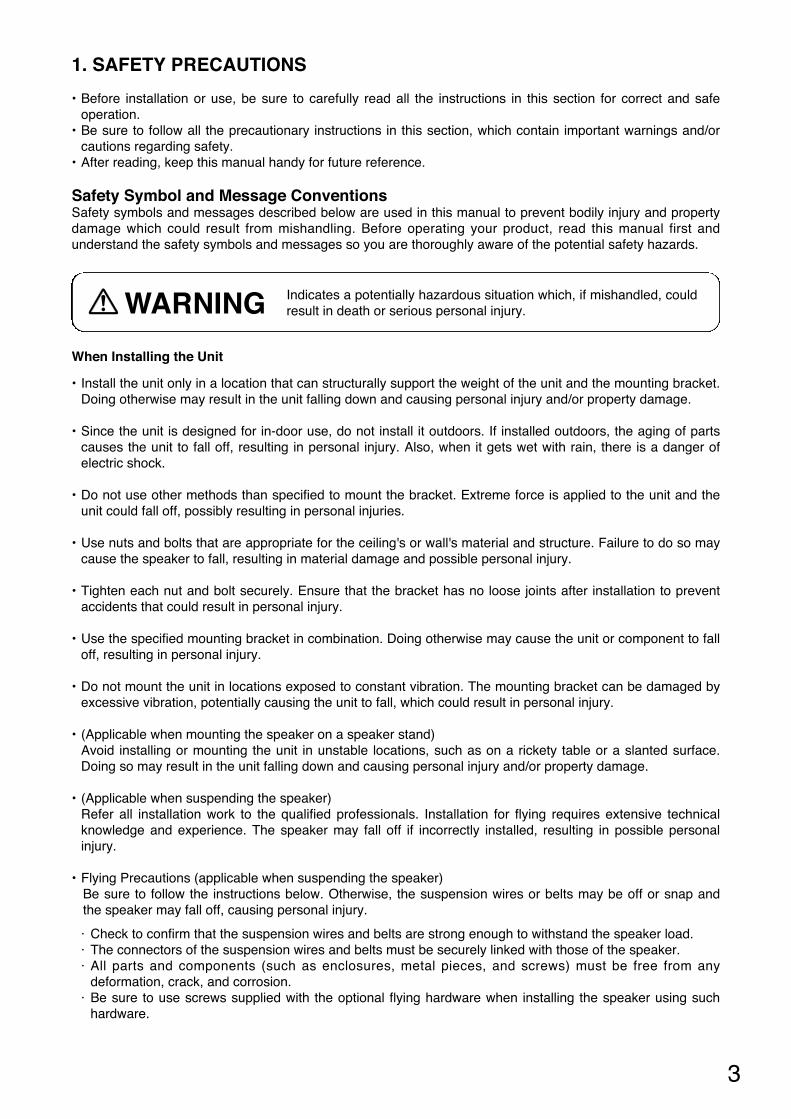
When Installing the Unit
• Install the unit only in a location that can structurally support the weight of the unit and the mounting bracket.Doing otherwise may result in the unit falling down and causing personal injury and/or property damage.
• Since the unit is designed for in-door use, do not install it outdoors. If installed outdoors, the aging of partscauses the unit to fall off, resulting in personal injury. Also, when it gets wet with rain, there is a danger ofelectric shock.
• Do not use other methods than specified to mount the bracket. Extreme force is applied to the unit and theunit could fall off, possibly resulting in personal injuries.
• Use nuts and bolts that are appropriate for the ceiling's or wall's material and structure. Failure to do so maycause the speaker to fall, resulting in material damage and possible personal injury.
• Tighten each nut and bolt securely. Ensure that the bracket has no loose joints after installation to preventaccidents that could result in personal injury.
• Use the specified mounting bracket in combination. Doing otherwise may cause the unit or component to falloff, resulting in personal injury.
• Do not mount the unit in locations exposed to constant vibration. The mounting bracket can be damaged byexcessive vibration, potentially causing the unit to fall, which could result in personal injury.
• (Applicable when mounting the speaker on a speaker stand)Avoid installing or mounting the unit in unstable locations, such as on a rickety table or a slanted surface.Doing so may result in the unit falling down and causing personal injury and/or property damage.
• (Applicable when suspending the speaker)Refer all installation work to the qualified professionals. Installation for flying requires extensive technicalknowledge and experience. The speaker may fall off if incorrectly installed, resulting in possible personalinjury.
• Flying Precautions (applicable when suspending the speaker) Be sure to follow the instructions below. Otherwise, the suspension wires or belts may be off or snap andthe speaker may fall off, causing personal injury.
· Check to confirm that the suspension wires and belts are strong enough to withstand the speaker load.· The connectors of the suspension wires and belts must be securely linked with those of the speaker.· All parts and components (such as enclosures, metal pieces, and screws) must be free from any
deformation, crack, and corrosion. · Be sure to use screws supplied with the optional flying hardware when installing the speaker using such
hardware.
1. SAFETY PRECAUTIONS
• Before installation or use, be sure to carefully read all the instructions in this section for correct and safeoperation.
• Be sure to follow all the precautionary instructions in this section, which contain important warnings and/orcautions regarding safety.
• After reading, keep this manual handy for future reference.
Safety Symbol and Message Conventions Safety symbols and messages described below are used in this manual to prevent bodily injury and propertydamage which could result from mishandling. Before operating your product, read this manual first andunderstand the safety symbols and messages so you are thoroughly aware of the potential safety hazards.
Indicates a potentially hazardous situation which, if mishandled, couldresult in death or serious personal injury. WARNING
4
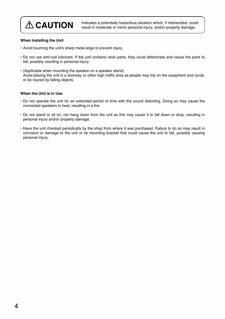
When Installing the Unit
• Avoid touching the unit's sharp metal edge to prevent injury.
• Do not use anti-rust lubricant. If the unit contains resin parts, they could deteriorate and cause the parts tofall, possibly resulting in personal injury.
• (Applicable when mounting the speaker on a speaker stand)Avoid placing the unit in a doorway or other high traffic area as people may trip on the equipment and cords,or be injured by falling objects.
When the Unit is in Use
• Do not operate the unit for an extended period of time with the sound distorting. Doing so may cause theconnected speakers to heat, resulting in a fire.
• Do not stand or sit on, nor hang down from the unit as this may cause it to fall down or drop, resulting inpersonal injury and/or property damage.
• Have the unit checked periodically by the shop from where it was purchased. Failure to do so may result incorrosion or damage to the unit or its mounting bracket that could cause the unit to fall, possibly causingpersonal injury.
Indicates a potentially hazardous situation which, if mishandled, couldresult in moderate or minor personal injury, and/or property damage.CAUTION
5
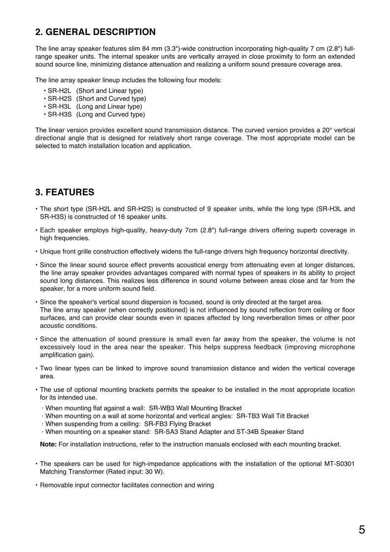
2. GENERAL DESCRIPTION
The line array speaker features slim 84 mm (3.3")-wide construction incorporating high-quality 7 cm (2.8") full-range speaker units. The internal speaker units are vertically arrayed in close proximity to form an extendedsound source line, minimizing distance attenuation and realizing a uniform sound pressure coverage area.
The line array speaker lineup includes the following four models:
• SR-H2L (Short and Linear type)• SR-H2S (Short and Curved type)• SR-H3L (Long and Linear type)• SR-H3S (Long and Curved type)
The linear version provides excellent sound transmission distance. The curved version provides a 20° verticaldirectional angle that is designed for relatively short range coverage. The most appropriate model can beselected to match installation location and application.
3. FEATURES
• The short type (SR-H2L and SR-H2S) is constructed of 9 speaker units, while the long type (SR-H3L andSR-H3S) is constructed of 16 speaker units.
• Each speaker employs high-quality, heavy-duty 7cm (2.8") full-range drivers offering superb coverage inhigh frequencies.
• Unique front grille construction effectively widens the full-range drivers high frequency horizontal directivity.
• Since the linear sound source effect prevents acoustical energy from attenuating even at longer distances,the line array speaker provides advantages compared with normal types of speakers in its ability to projectsound long distances. This realizes less difference in sound volume between areas close and far from thespeaker, for a more uniform sound field.
• Since the speaker's vertical sound dispersion is focused, sound is only directed at the target area. The line array speaker (when correctly positioned) is not influenced by sound reflection from ceiling or floorsurfaces, and can provide clear sounds even in spaces affected by long reverberation times or other pooracoustic conditions.
• Since the attenuation of sound pressure is small even far away from the speaker, the volume is notexcessively loud in the area near the speaker. This helps suppress feedback (improving microphoneamplification gain).
• Two linear types can be linked to improve sound transmission distance and widen the vertical coveragearea.
• The use of optional mounting brackets permits the speaker to be installed in the most appropriate locationfor its intended use.
· When mounting flat against a wall: SR-WB3 Wall Mounting Bracket · When mounting on a wall at some horizontal and vertical angles: SR-TB3 Wall Tilt Bracket· When suspending from a ceiling: SR-FB3 Flying Bracket· When mounting on a speaker stand: SR-SA3 Stand Adapter and ST-34B Speaker Stand
Note: For installation instructions, refer to the instruction manuals enclosed with each mounting bracket.
• The speakers can be used for high-impedance applications with the installation of the optional MT-S0301Matching Transformer (Rated input: 30 W).
• Removable input connector facilitates connection and wiring
6
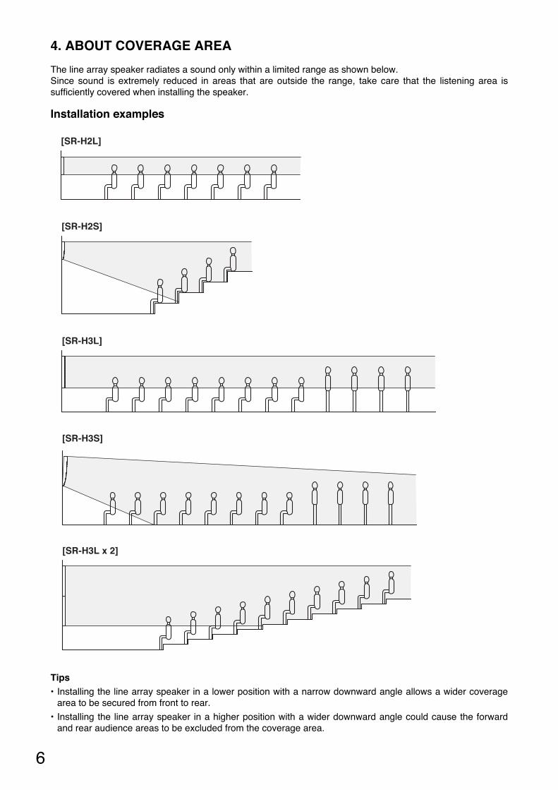
4. ABOUT COVERAGE AREA
The line array speaker radiates a sound only within a limited range as shown below. Since sound is extremely reduced in areas that are outside the range, take care that the listening area issufficiently covered when installing the speaker.
Installation examples
Tips• Installing the line array speaker in a lower position with a narrow downward angle allows a wider coverage
area to be secured from front to rear.
• Installing the line array speaker in a higher position with a wider downward angle could cause the forwardand rear audience areas to be excluded from the coverage area.
[SR-H3L]
[SR-H3S]
[SR-H2L]
[SR-H2S]
[SR-H3L x 2]
7
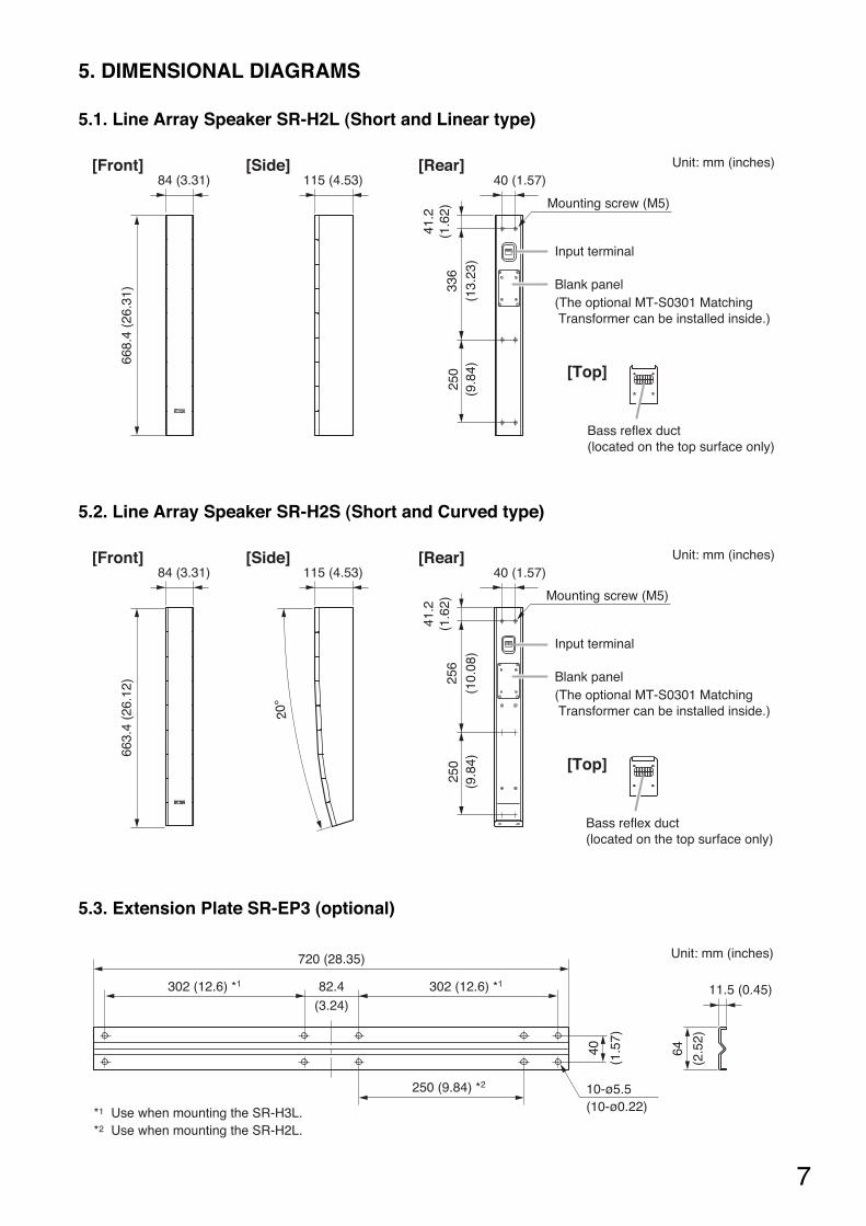
5. DIMENSIONAL DIAGRAMS
5.2. Line Array Speaker SR-H2S (Short and Curved type)
5.1. Line Array Speaker SR-H2L (Short and Linear type)
5.3. Extension Plate SR-EP3 (optional)
[Front] [Rear][Side] Unit: mm (inches)84 (3.31) 115 (4.53)
668.
4 (2
6.31
)
Input terminal
Blank panel(The optional MT-S0301 Matching Transformer can be installed inside.)
[Top]
336
(13.
23)
250
(9.8
4)
41.2
(1.6
2)Bass reflex duct(located on the top surface only)
40 (1.57)
Mounting screw (M5)
20°
[Front]84 (3.31)
663.
4 (2
6.12
)
[Side]115 (4.53)
[Rear] Unit: mm (inches)
Input terminal
Blank panel(The optional MT-S0301 Matching Transformer can be installed inside.)
[Top]
256
(10.
08)
250
(9.8
4)
41.2
(1.6
2)
Bass reflex duct(located on the top surface only)
40 (1.57)
Mounting screw (M5)
Unit: mm (inches)
64
(2.5
2)
40
(1.5
7)
82.4(3.24)
720 (28.35)
10-ø5.5(10-ø0.22)
11.5 (0.45)302 (12.6) *1 302 (12.6) *1
250 (9.84) *2
*1 Use when mounting the SR-H3L.*2 Use when mounting the SR-H2L.
8
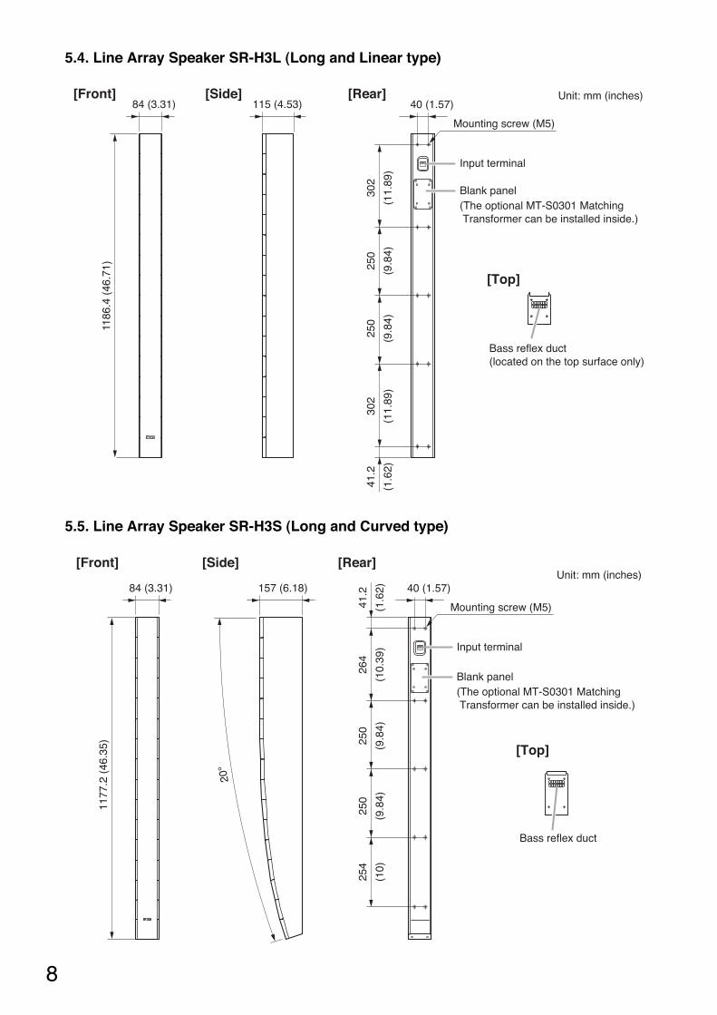
5.5. Line Array Speaker SR-H3S (Long and Curved type)
5.4. Line Array Speaker SR-H3L (Long and Linear type)
1186
.4 (
46.7
1)
302
(11.
89)
250
(9.8
4)
250
(9.8
4)
302
(11.
89)
41.2
(1.6
2)
[Front] [Rear][Side]84 (3.31) 115 (4.53) 40 (1.57)
[Top]
Unit: mm (inches)
Input terminal
Blank panel(The optional MT-S0301 Matching Transformer can be installed inside.)
Bass reflex duct(located on the top surface only)
Mounting screw (M5)
20°
264
(10.
39)
250
(9.8
4)
250
(9.8
4)
254
(10)
41.2
(1.6
2)
1177
.2 (
46.3
5)
[Front] [Rear][Side]
84 (3.31) 157 (6.18) 40 (1.57)
[Top]
Unit: mm (inches)
Input terminal
Blank panel(The optional MT-S0301 Matching Transformer can be installed inside.)
Bass reflex duct
Mounting screw (M5)
9
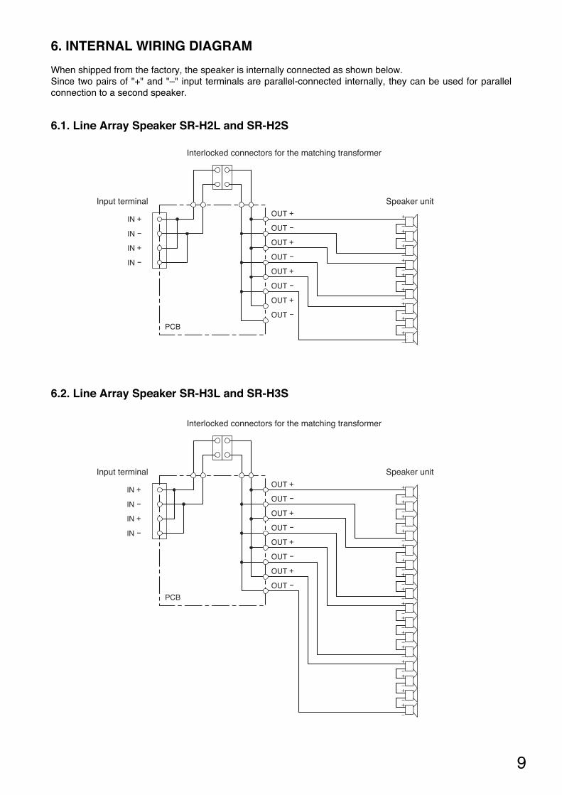
6. INTERNAL WIRING DIAGRAM
When shipped from the factory, the speaker is internally connected as shown below. Since two pairs of "+" and "–" input terminals are parallel-connected internally, they can be used for parallelconnection to a second speaker.
6.1. Line Array Speaker SR-H2L and SR-H2S
OUT +IN +
OUT -
OUT +
OUT -
OUT +
OUT -
OUT +
OUT -
IN -
IN +
IN -
PCB
Speaker unit
Interlocked connectors for the matching transformer
Input terminal
6.2. Line Array Speaker SR-H3L and SR-H3S
OUT +IN +
OUT -
OUT +
OUT -
OUT +
OUT -
OUT +
OUT -
IN -
IN +
IN -
PCB
Speaker unit
Interlocked connectors for the matching transformer
Input terminal
10
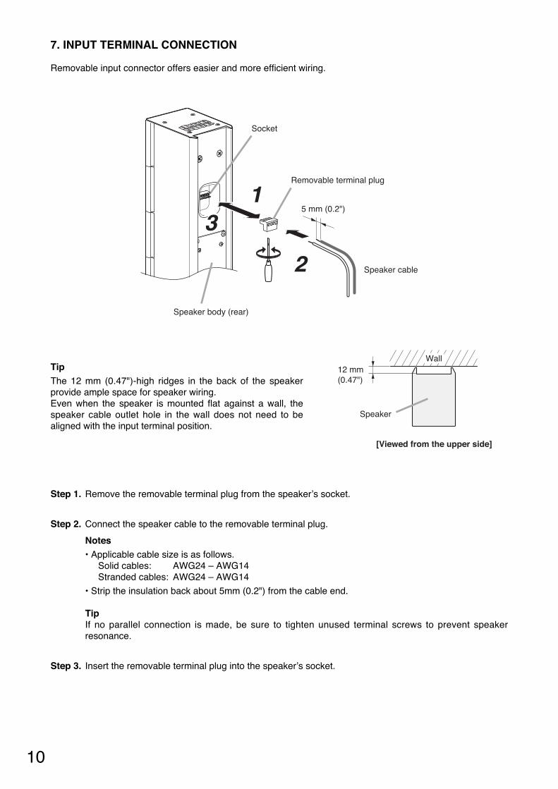
7. INPUT TERMINAL CONNECTION
Removable input connector offers easier and more efficient wiring.
5 mm (0.2")
Speaker body (rear)
Removable terminal plug
Socket
Speaker cable
13
2
12 mm(0.47")
Speaker
Wall
[Viewed from the upper side]
TipThe 12 mm (0.47")-high ridges in the back of the speakerprovide ample space for speaker wiring. Even when the speaker is mounted flat against a wall, thespeaker cable outlet hole in the wall does not need to bealigned with the input terminal position.
Step 1. Remove the removable terminal plug from the speaker’s socket.
Step 2. Connect the speaker cable to the removable terminal plug.
Notes• Applicable cable size is as follows.
Solid cables: AWG24 – AWG14 Stranded cables: AWG24 – AWG14
• Strip the insulation back about 5mm (0.2") from the cable end.
Tip If no parallel connection is made, be sure to tighten unused terminal screws to prevent speakerresonance.
Step 3. Insert the removable terminal plug into the speaker’s socket.
11
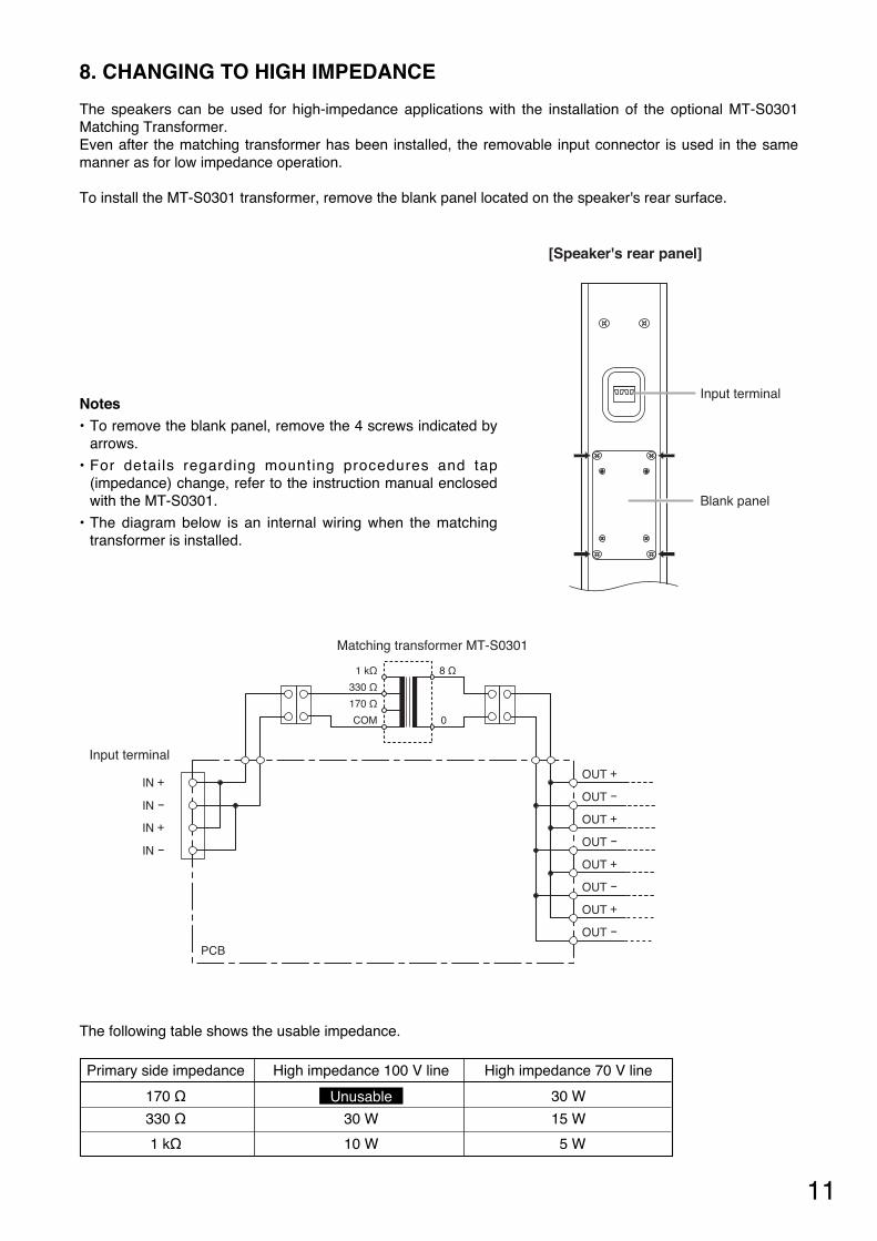
8. CHANGING TO HIGH IMPEDANCE
The speakers can be used for high-impedance applications with the installation of the optional MT-S0301Matching Transformer.Even after the matching transformer has been installed, the removable input connector is used in the samemanner as for low impedance operation.
To install the MT-S0301 transformer, remove the blank panel located on the speaker's rear surface.
Primary side impedance High impedance 100 V line High impedance 70 V line
170 Ω 30 W
330 Ω 30 W 15 W
1 kΩ 10 W 5 W
Unusable
The following table shows the usable impedance.
[Speaker's rear panel]
Input terminal
Blank panel
Notes• To remove the blank panel, remove the 4 screws indicated by
arrows.
• For details regarding mounting procedures and tap(impedance) change, refer to the instruction manual enclosedwith the MT-S0301.
• The diagram below is an internal wiring when the matchingtransformer is installed.
OUT +IN +
Matching transformer MT-S0301
1 kΩ 8 Ω
0
330 Ω
170 Ω
COM
OUT -
OUT +
OUT -
OUT +
OUT -
OUT +
OUT -
IN -
IN +
IN -
PCB
Input terminal
12
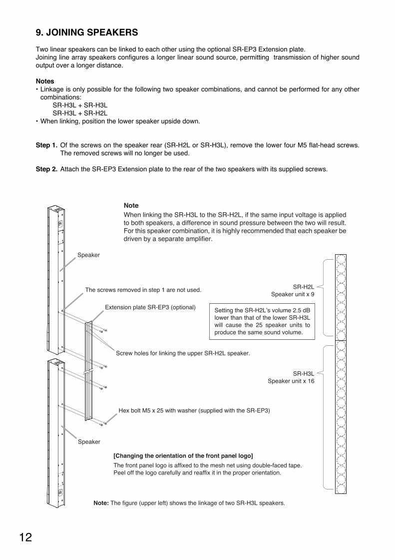
9. JOINING SPEAKERS
Two linear speakers can be linked to each other using the optional SR-EP3 Extension plate. Joining line array speakers configures a longer linear sound source, permitting transmission of higher soundoutput over a longer distance.
Notes • Linkage is only possible for the following two speaker combinations, and cannot be performed for any other
combinations: SR-H3L + SR-H3L SR-H3L + SR-H2L
• When linking, position the lower speaker upside down.
Step 1. Of the screws on the speaker rear (SR-H2L or SR-H3L), remove the lower four M5 flat-head screws.The removed screws will no longer be used.
Step 2. Attach the SR-EP3 Extension plate to the rear of the two speakers with its supplied screws.
Extension plate SR-EP3 (optional)
Screw holes for linking the upper SR-H2L speaker.
The screws removed in step 1 are not used.
Speaker
Speaker
Note: The figure (upper left) shows the linkage of two SR-H3L speakers.
Hex bolt M5 x 25 with washer (supplied with the SR-EP3)
NoteWhen linking the SR-H3L to the SR-H2L, if the same input voltage is applied to both speakers, a difference in sound pressure between the two will result. For this speaker combination, it is highly recommended that each speaker be driven by a separate amplifier.
SR-H2LSpeaker unit x 9
SR-H3LSpeaker unit x 16
Setting the SR-H2L’s volume 2.5 dB lower than that of the lower SR-H3L will cause the 25 speaker units to produce the same sound volume.
[Changing the orientation of the front panel logo]
The front panel logo is affixed to the mesh net using double-faced tape.Peel off the logo carefully and reaffix it in the proper orientation.
13
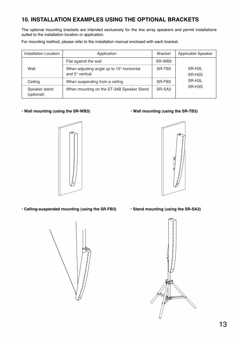
10. INSTALLATION EXAMPLES USING THE OPTIONAL BRACKETS
The optional mounting brackets are intended exclusively for the line array speakers and permit installationssuited to the installation location or application.
For mounting method, please refer to the installation manual enclosed with each bracket.
• Wall mounting (using the SR-WB3) • Wall mounting (using the SR-TB3)
• Ceiling-suspended mounting (using the SR-FB3) • Stand mounting (using the SR-SA3)
Installation Location
Wall
Ceiling
Speaker stand(optional)
Applicable SpeakerApplication Bracket
SR-H2L
SR-H2S
SR-H3L
SR-H3S
Flat against the wall
When adjusting angle up to 15° horizontal and 5° vertical
When suspending from a ceiling
When mounting on the ST-34B Speaker Stand
SR-WB3
SR-TB3
SR-FB3
SR-SA3
14
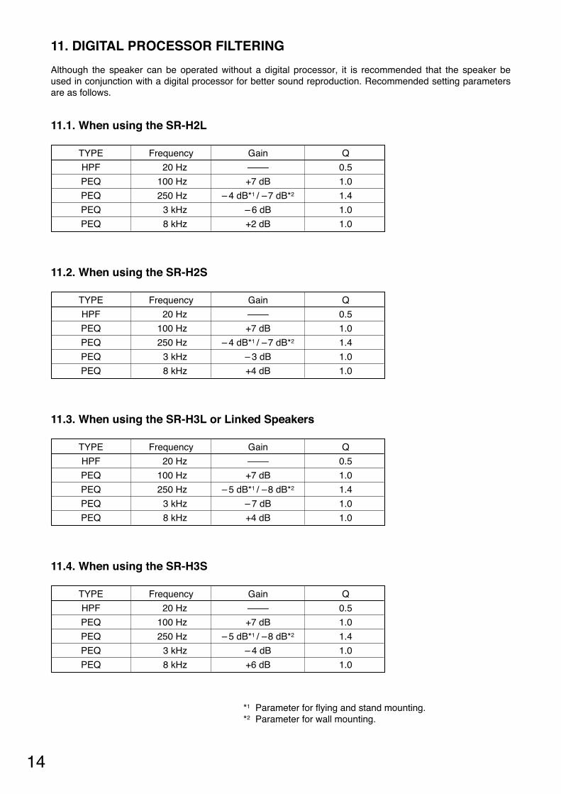
11. DIGITAL PROCESSOR FILTERING
Although the speaker can be operated without a digital processor, it is recommended that the speaker beused in conjunction with a digital processor for better sound reproduction. Recommended setting parametersare as follows.
11.1. When using the SR-H2L
11.2. When using the SR-H2S
Q
0.5
1.0
1.4
1.0
1.0
TYPE
HPF
PEQ
PEQ
PEQ
PEQ
Frequency
20 Hz
100 Hz
250 Hz
3 kHz
8 kHz
Gain
–
+7 dB
– 4 dB*1 / –7 dB*2
– 6 dB
+2 dB
Q
0.5
1.0
1.4
1.0
1.0
TYPE
HPF
PEQ
PEQ
PEQ
PEQ
Frequency
20 Hz
100 Hz
250 Hz
3 kHz
8 kHz
Gain
–
+7 dB
– 4 dB*1 / –7 dB*2
– 3 dB
+4 dB
*1 Parameter for flying and stand mounting.*2 Parameter for wall mounting.
11.3. When using the SR-H3L or Linked Speakers
11.4. When using the SR-H3S
Q
0.5
1.0
1.4
1.0
1.0
TYPE
HPF
PEQ
PEQ
PEQ
PEQ
Frequency
20 Hz
100 Hz
250 Hz
3 kHz
8 kHz
Gain
–
+7 dB
– 5 dB*1 / –8 dB*2
– 7 dB
+4 dB
Q
0.5
1.0
1.4
1.0
1.0
TYPE
HPF
PEQ
PEQ
PEQ
PEQ
Frequency
20 Hz
100 Hz
250 Hz
3 kHz
8 kHz
Gain
–
+7 dB
– 5 dB*1 / –8 dB*2
– 4 dB
+6 dB

15
Model No. SR-H2L SR-H2SEnclosure Bass-reflex typePower Handling Capacity Continuous program: 180 WRated Impedance 8 ΩSensitivity 92 dB
(1 W, 1 m equivalent, measured at 4 m)90 dB (1 W, 1 m equivalent, measured at 4 m)
Frequency Response 80 Hz − 18 kHz* 90 Hz − 17 kHz*Directivity Angle Horizontal: 90°
Vertical: 0° (within the range of speaker height)Horizontal: 90°Vertical: 20°
Speaker Component 7 cm (2.8") cone-type x 9Input Connector Removable input connectorFinish Enclosure: MDF, white, urethane paint
Front grille: Punched steel plate, white, acrylic paintDimensions 84 (w) x 668.4 (h) x 115 (d) mm
(3.31" x 26.31" x 4.53")84 (w) x 663.4 (h) x 115 (d) mm
(3.31" x 26.12" x 4.53")Weight 4.4 kg (9.7 lb) 4.2 kg (9.26 lb)Option
* When recommended parameters are applied by the optional digital speaker processor DP-SP3
Note: The design and specifications are subject to change without notice for improvement.
12. SPECIFICATIONS12.1. Line Array Speakers SR-H2L and SR-H2S
12.2. Line Array Speakers SR-H3L and SR-H3S
Model No. SR-H3L SR-H3SEnclosure Bass-reflex typePower Handling Capacity Continuous program: 360 WRated Impedance 8 ΩSensitivity 95 dB
(1 W, 1 m equivalent, measured at 8 m)92 dB (1 W, 1 m equivalent, measured at 8 m)
Frequency Response 110 Hz − 18 kHz* 90 Hz − 17 kHz*Directivity Angle Horizontal: 90°
Vertical: 0° (within the range of speaker height)Horizontal: 90°Vertical: 20°
Speaker Component 7 cm (2.8") cone-type x 16Input Connector Removable input connectorFinish Enclosure: MDF, white, urethane paint
Front grille: Punched steel plate, white, acrylic paintDimensions 84 (w) x 1186.4 (h) x 115 (d) mm
(3.31" x 46.71" x 4.53")84 (w) x 1177.2 (h) x 157 (d) mm
(3.31" x 46.35" x 6.18")Weight 7.6 kg (16.75 lb) 7.9 kg (17.42 lb)Option
* When recommended parameters are applied by the optional digital speaker processor DP-SP3
Note: The design and specifications are subject to change without notice for improvement.
Matching transformer: MT-S0301Extension plate: SR-EP3Wall mounting bracket: SR-WB3Wall tilt bracket: SR-TB3Flying bracket: SR-FB3
Stand adapter: SR-SA3 (Applicable stand :ST-34B)Digital speaker processor: DP-SP3
Matching transformer: MT-S0301Extension plate: SR-EP3Wall mounting bracket: SR-WB3Wall tilt bracket: SR-TB3Flying bracket: SR-FB3
Stand adapter: SR-SA3 (Applicable stand :ST-34B)Digital speaker processor: DP-SP3
Traceability Information for EuropeManufacturer:
TOA Corporation7-2-1, Minatojima-Nakamachi, Chuo-ku, Kobe, Hyogo, Japan
Authorized representative:TOA Electronics Europe GmbHSuederstrasse 282, 20537 Hamburg,Germany
URL: http://www.toa.jp/
133-01-00154-00
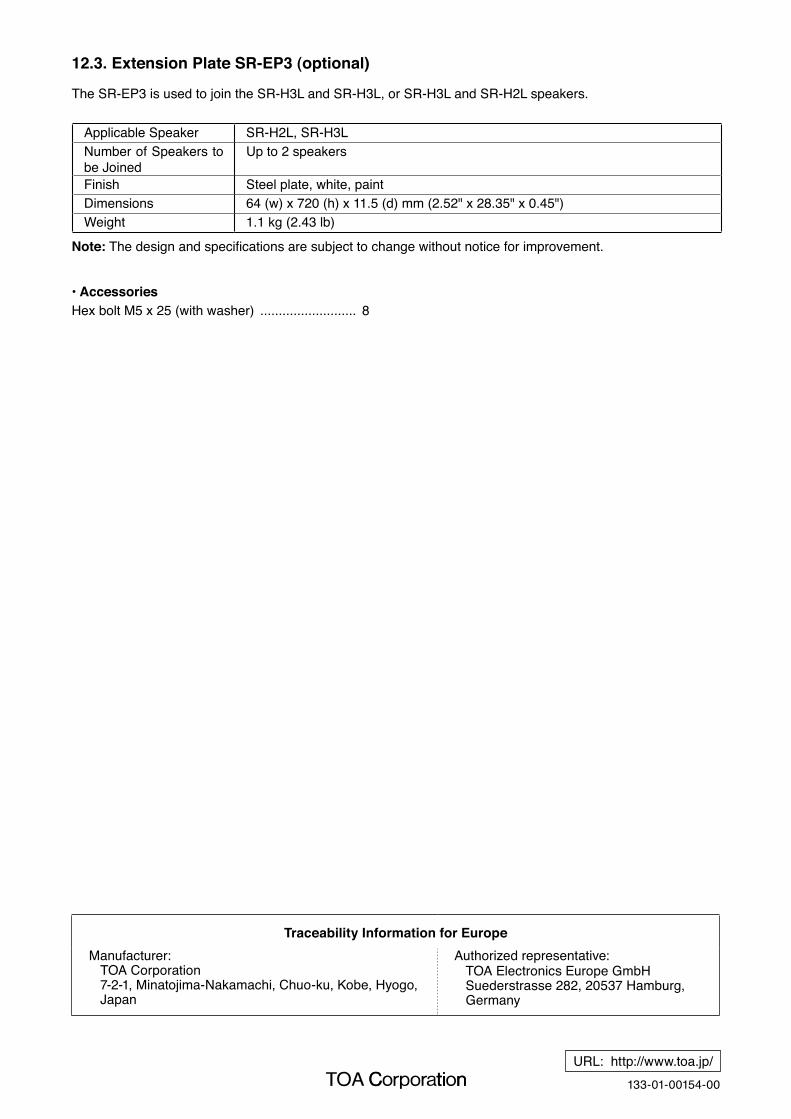
Applicable Speaker SR-H2L, SR-H3LNumber of Speakers to be Joined
Up to 2 speakers
Finish Steel plate, white, paintDimensions 64 (w) x 720 (h) x 11.5 (d) mm (2.52" x 28.35" x 0.45")Weight 1.1 kg (2.43 lb)
• AccessoriesHex bolt M5 x 25 (with washer) .......................... 8
12.3. Extension Plate SR-EP3 (optional)
The SR-EP3 is used to join the SR-H3L and SR-H3L, or SR-H3L and SR-H2L speakers.
Note: The design and specifications are subject to change without notice for improvement.