LINCOLN - National Highway Traffic Safety …LINCOLN: 2013-2015 MKS This article supersedes TSB...
82
Transcript of LINCOLN - National Highway Traffic Safety …LINCOLN: 2013-2015 MKS This article supersedes TSB...
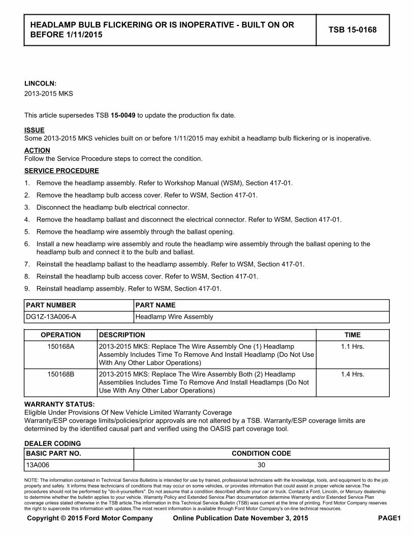
LINCOLN:2013-2015 MKS
This article supersedes TSB 15-0049 to update the production fix date.
ISSUESome 2013-2015 MKS vehicles built on or before 1/11/2015 may exhibit a headlamp bulb flickering or is inoperative.
ACTIONFollow the Service Procedure steps to correct the condition.
SERVICE PROCEDURE
1. Remove the headlamp assembly. Refer to Workshop Manual (WSM), Section 417-01.
2. Remove the headlamp bulb access cover. Refer to WSM, Section 417-01.
3. Disconnect the headlamp bulb electrical connector.
4. Remove the headlamp ballast and disconnect the electrical connector. Refer to WSM, Section 417-01.
5. Remove the headlamp wire assembly through the ballast opening.
6. Install a new headlamp wire assembly and route the headlamp wire assembly through the ballast opening to theheadlamp bulb and connect it to the bulb and ballast.
7. Reinstall the headlamp ballast to the headlamp assembly. Refer to WSM, Section 417-01.
8. Reinstall the headlamp bulb access cover. Refer to WSM, Section 417-01.
9. Reinstall headlamp assembly. Refer to WSM, Section 417-01.
PART NUMBER PART NAMEDG1Z-13A006-A Headlamp Wire Assembly
OPERATION DESCRIPTION TIME150168A 2013-2015 MKS: Replace The Wire Assembly One (1) Headlamp
Assembly Includes Time To Remove And Install Headlamp (Do Not UseWith Any Other Labor Operations)
1.1 Hrs.
150168B 2013-2015 MKS: Replace The Wire Assembly Both (2) HeadlampAssemblies Includes Time To Remove And Install Headlamps (Do NotUse With Any Other Labor Operations)
1.4 Hrs.
WARRANTY STATUS:Eligible Under Provisions Of New Vehicle Limited Warranty CoverageWarranty/ESP coverage limits/policies/prior approvals are not altered by a TSB. Warranty/ESP coverage limits aredetermined by the identified causal part and verified using the OASIS part coverage tool.
DEALER CODINGBASIC PART NO. CONDITION CODE13A006 30
HEADLAMP BULB FLICKERING OR IS INOPERATIVE - BUILT ON ORBEFORE 1/11/2015 TSB 15-0168
NOTE: The information contained in Technical Service Bulletins is intended for use by trained, professional technicians with the knowledge, tools, and equipment to do the jobproperly and safely. It informs these technicians of conditions that may occur on some vehicles, or provides information that could assist in proper vehicle service.Theprocedures should not be performed by "do-it-yourselfers". Do not assume that a condition described affects your car or truck. Contact a Ford, Lincoln, or Mercury dealershipto determine whether the bulletin applies to your vehicle. Warranty Policy and Extended Service Plan documentation determine Warranty and/or Extended Service Plancoverage unless stated otherwise in the TSB article.The information in this Technical Service Bulletin (TSB) was current at the time of printing. Ford Motor Company reservesthe right to supercede this information with updates.The most recent information is available through Ford Motor Company's on-line technical resources.
Copyright © 2015 Ford Motor Company Online Publication Date November 3, 2015 PAGE1
FORD:2016 Explorer
ISSUESome 2016 Explorer vehicles may have a front seat cushion cover that appears loose near the front edge of the seat. Thismay be caused by the seat cushion cover J-retainer becoming disengaged from the seat cushion pan flange.
ACTIONFollow the Service Procedure steps to correct the condition.
SERVICE PROCEDURE
Install two (2) retention clips on the seat cushion cover J-retainer.
The following procedure and part are applicable to all 2016 Explorer front seat configurations, trim levels, right and/or leftside.
1. Position the affected seat rearward.
2. Completely disengage the J-retainer from the seat cushion pan flange.
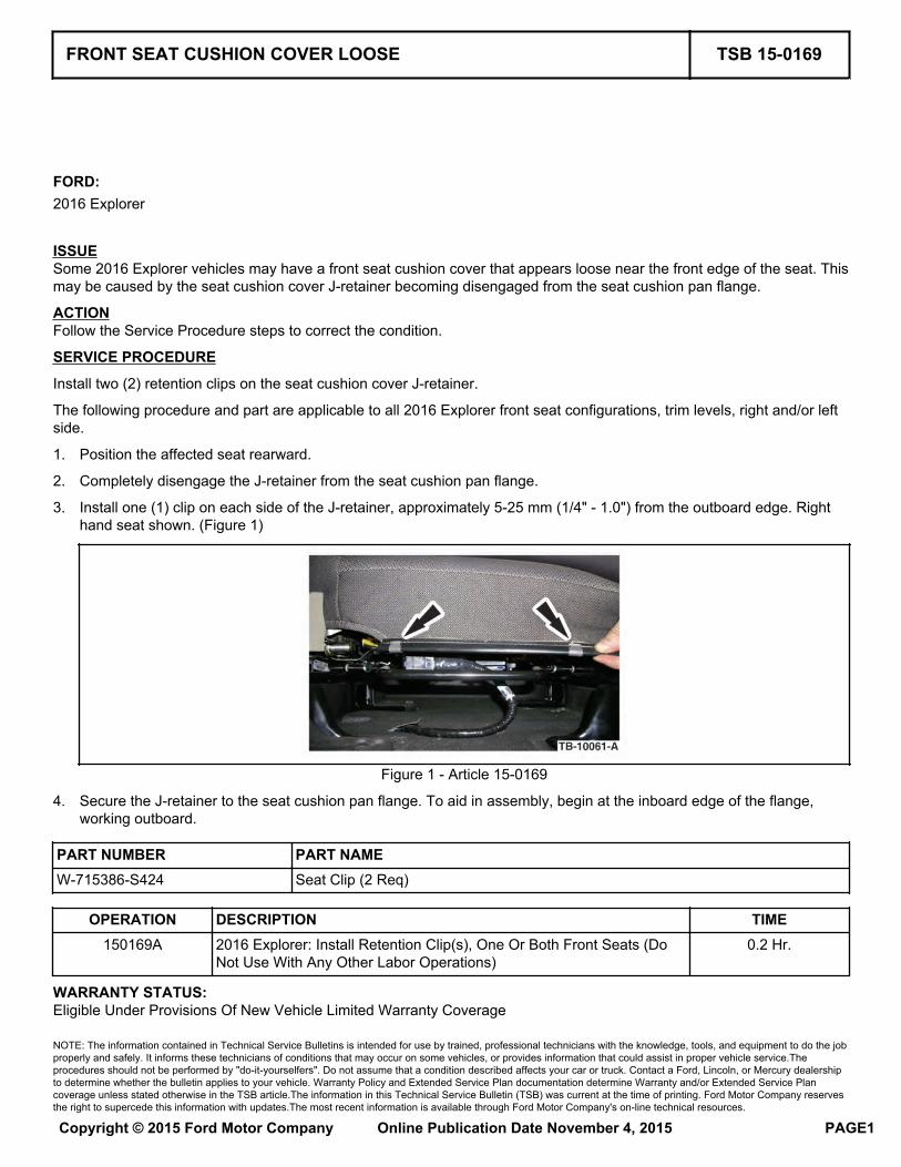
3. Install one (1) clip on each side of the J-retainer, approximately 5-25 mm (1/4" - 1.0") from the outboard edge. Righthand seat shown. (Figure 1)
Figure 1 - Article 15-0169
4. Secure the J-retainer to the seat cushion pan flange. To aid in assembly, begin at the inboard edge of the flange,working outboard.
PART NUMBER PART NAMEW-715386-S424 Seat Clip (2 Req)
OPERATION DESCRIPTION TIME150169A 2016 Explorer: Install Retention Clip(s), One Or Both Front Seats (Do
Not Use With Any Other Labor Operations)0.2 Hr.
WARRANTY STATUS:Eligible Under Provisions Of New Vehicle Limited Warranty Coverage
FRONT SEAT CUSHION COVER LOOSE TSB 15-0169
NOTE: The information contained in Technical Service Bulletins is intended for use by trained, professional technicians with the knowledge, tools, and equipment to do the jobproperly and safely. It informs these technicians of conditions that may occur on some vehicles, or provides information that could assist in proper vehicle service.Theprocedures should not be performed by "do-it-yourselfers". Do not assume that a condition described affects your car or truck. Contact a Ford, Lincoln, or Mercury dealershipto determine whether the bulletin applies to your vehicle. Warranty Policy and Extended Service Plan documentation determine Warranty and/or Extended Service Plancoverage unless stated otherwise in the TSB article.The information in this Technical Service Bulletin (TSB) was current at the time of printing. Ford Motor Company reservesthe right to supercede this information with updates.The most recent information is available through Ford Motor Company's on-line technical resources.
Copyright © 2015 Ford Motor Company Online Publication Date November 4, 2015 PAGE1
Warranty/ESP coverage limits/policies/prior approvals are not altered by a TSB. Warranty/ESP coverage limits aredetermined by the identified causal part and verified using the OASIS part coverage tool.
DEALER CODINGBASIC PART NO. CONDITION CODE7062900 33
TSB 15-0169 (Continued)
PAGE2
FORD:2015 TaurusLINCOLN:2015 MKS
ISSUESome 2015 Taurus and MKS vehicles equipped with a 3.5L Gasoline Turbocharged Direct Injection (GTDI) engine andbuilt on 9/22/2015 and through 10/21/2015 may exhibit a MIL on with diagnostic trouble code (DTC) P0012 and/or P0022.
ACTIONReprogram the powertrain control module (PCM) to the latest calibration using IDS release 97.05 or higher. Make sureyou are connected to the internet when entering module programming to obtain the latest updates. Calibration files mayalso be obtained at www.motorcraftservice.com.
OPERATION DESCRIPTION TIME150170A 2015 Taurus And MKS 3.5L GTDI: Retrieve DTCs And Reprogram The
PCM (Do Not Use With Any Other Labor Operations)0.3 Hr.
WARRANTY STATUS:Eligible Under Provisions Of New Vehicle Limited Warranty Coverage And Emissions Warranty CoverageWarranty/ESP coverage limits/policies/prior approvals are not altered by a TSB. Warranty/ESP coverage limits aredetermined by the identified causal part and verified using the OASIS part coverage tool.
DEALER CODINGBASIC PART NO. CONDITION CODERECALEM 04
3.5L GTDI - MALFUNCTION INDICATOR LAMP (MIL) ON WITHDIAGNOSTIC TROUBLE CODES (DTC) P0012 AND/OR P0022 - BUILT ON9/22/2015 AND THROUGH 10/21/2015
TSB 15-0170
NOTE: The information contained in Technical Service Bulletins is intended for use by trained, professional technicians with the knowledge, tools, and equipment to do the jobproperly and safely. It informs these technicians of conditions that may occur on some vehicles, or provides information that could assist in proper vehicle service.Theprocedures should not be performed by "do-it-yourselfers". Do not assume that a condition described affects your car or truck. Contact a Ford, Lincoln, or Mercury dealershipto determine whether the bulletin applies to your vehicle. Warranty Policy and Extended Service Plan documentation determine Warranty and/or Extended Service Plancoverage unless stated otherwise in the TSB article.The information in this Technical Service Bulletin (TSB) was current at the time of printing. Ford Motor Company reservesthe right to supercede this information with updates.The most recent information is available through Ford Motor Company's on-line technical resources.
Copyright © 2015 Ford Motor Company Online Publication Date November 4, 2015 PAGE1
FORD:2015 F-150
ISSUESome 2015 F-150 vehicles equipped with a 2.7L gasoline turbocharged direct injected (GTDI) engine and built on orbefore 10/5/2015 may exhibit an illuminated malfunction indicator lamp (MIL) with diagnostic trouble code (DTC) P2450.
ACTIONFollow the Service Procedure steps to correct the condition.
SERVICE PROCEDURE
1. Connect the Ford Integrated Diagnostic System (IDS) service tool or equivalent to the data link connector (DLC). IsDTC P2450 the only DTC stored in powertrain control module (PCM)?
a. Yes - proceed to Step 2.
b. No - this article does not apply. Refer to Powertrain Control/Emission Diagnosis (PC/ED) manual for normaldiagnosis.
2. Replace the fuel tank mounted evaporative emission blocking valve. Refer to Workshop Manual (WSM), Section303-13.
a. The evaporative emission blocking valve is serviced with the fuel tank pressure sensor and tube.
PART NUMBER PART NAMEFL3Z-9D683-F Fuel Tank Pressure Sensor And Tube (23 Gallon Fuel Tank Excludes 122" Wheel
Base)
FL3Z-9D683-D Fuel Tank Pressure Sensor And Tube (36 Gallon Fuel Tank)
FL3Z-9D683-B Fuel Tank Pressure Sensor And Tube ( 23 Gallon Fuel Tank 122" Wheel Base)
N800594-S100 Bolt - Pinion Flange/Transmission Flange
W715579-S439 Bolt - Driveshaft Center Bearing
W717158-S441 Nut - Driveshaft Center Bearing
OPERATION DESCRIPTION TIME150171A 2015 F150 2.7L GTDI One Piece Driveshaft: Retrieve DTCs Replace
The Evaporative Emission Blocking Valve Includes Time To RemoveAnd Install Fuel Tank (Do Not Use With Any Other Labor Operations)
1.6 Hrs.
150171B 2015 F150 2.7L GTDI Two Piece Driveshaft: Retrieve DTCs ReplaceThe Evaporative Emission Blocking Valve Includes Time To RemoveAnd Install Fuel Tank (Do Not Use With Any Other Labor Operations)
1.8 Hrs.
WARRANTY STATUS:Eligible Under Provisions Of New Vehicle Limited Warranty Coverage And Emissions Warranty CoverageWarranty/ESP coverage limits/policies/prior approvals are not altered by a TSB. Warranty/ESP coverage limits aredetermined by the identified causal part and verified using the OASIS part coverage tool.
2.7L GTDI - MIL ILLUMINATED WITH DTC P2450 - BUILT ON OR BEFORE10/5/2015 TSB 15-0171
NOTE: The information contained in Technical Service Bulletins is intended for use by trained, professional technicians with the knowledge, tools, and equipment to do the jobproperly and safely. It informs these technicians of conditions that may occur on some vehicles, or provides information that could assist in proper vehicle service.Theprocedures should not be performed by "do-it-yourselfers". Do not assume that a condition described affects your car or truck. Contact a Ford, Lincoln, or Mercury dealershipto determine whether the bulletin applies to your vehicle. Warranty Policy and Extended Service Plan documentation determine Warranty and/or Extended Service Plancoverage unless stated otherwise in the TSB article.The information in this Technical Service Bulletin (TSB) was current at the time of printing. Ford Motor Company reservesthe right to supercede this information with updates.The most recent information is available through Ford Motor Company's on-line technical resources.
Copyright © 2015 Ford Motor Company Online Publication Date November 5, 2015 PAGE1
DEALER CODINGBASIC PART NO. CONDITION CODE9G712 42
TSB 15-0171 (Continued)
PAGE2
FORD:2016 Fusion
ISSUESome 2016 Fusion vehicles equipped with a 1.5L gasoline turbocharged direct injected (GTDI) engine and built on orbefore 8/22/2015 may exhibit an illuminated MIL with one or more of the following diagnostic trouble codes (DTCs):P0036, P0137, P0138 and/or P0141.
ACTIONFollow the Service Procedure steps to correct the condition.
SERVICE PROCEDURE
1. Using an Integrated Diagnostic System (IDS) or equivalent scan tool check for DTCs. Is DTC P0036, P0137, P0138and/or P0141 present in powertrain control module (PCM) memory?
a. Yes - proceed to Step 2.
b. No - this article does not apply. Refer to Powertrain Control/Emissions Diagnosis (PC/ED) manual for normaldiagnostics.
2. Reprogram the PCM to the latest calibration using IDS release 97.01 or higher. Make sure you are connected to theinternet when entering module programming to obtain the latest updates. Calibration files may also be obtained atwww.motorcraftservice.com.
3. Replace the bank 1, sensor 2 catalyst monitor sensor (CMS). Refer to Workshop Manual (WSM), Section 303-14.
PART NUMBER PART NAMEDS7Z-9G444-A Catalyst Monitor Sensor
OPERATION DESCRIPTION TIME150172A 2016 Fusion 1.5L GTDI: Retrieve DTCs, Reprogram The PCM And
Replace The CMS (Do Not Use With Any Other Labor Operations)0.8 Hr.
WARRANTY STATUS:Eligible Under Provisions Of New Vehicle Limited Warranty Coverage And Emissions Warranty CoverageWarranty/ESP coverage limits/policies/prior approvals are not altered by a TSB. Warranty/ESP coverage limits aredetermined by the identified causal part and verified using the OASIS part coverage tool.
DEALER CODINGBASIC PART NO. CONDITION CODE9G444 01
1.5L GTDI - MALFUNCTION INDICATOR LAMP (MIL) ILLUMINATED WITHDTCS P0036, P0137, P0138 AND/OR P0141 - BUILT ON OR BEFORE8/22/2015
TSB 15-0172
NOTE: The information contained in Technical Service Bulletins is intended for use by trained, professional technicians with the knowledge, tools, and equipment to do the jobproperly and safely. It informs these technicians of conditions that may occur on some vehicles, or provides information that could assist in proper vehicle service.Theprocedures should not be performed by "do-it-yourselfers". Do not assume that a condition described affects your car or truck. Contact a Ford, Lincoln, or Mercury dealershipto determine whether the bulletin applies to your vehicle. Warranty Policy and Extended Service Plan documentation determine Warranty and/or Extended Service Plancoverage unless stated otherwise in the TSB article.The information in this Technical Service Bulletin (TSB) was current at the time of printing. Ford Motor Company reservesthe right to supercede this information with updates.The most recent information is available through Ford Motor Company's on-line technical resources.
Copyright © 2015 Ford Motor Company Online Publication Date November 5, 2015 PAGE1
LINCOLN:2015-2016 MKC
ISSUESome 2015-2016 MKC vehicles built on or before 7/24/2015 may exhibit a front seat backrest cover zipper separated,split or broken due to excessive trim cover tension.
ACTIONFollow the Service Procedure steps to correct the condition.
SERVICE PROCEDURE
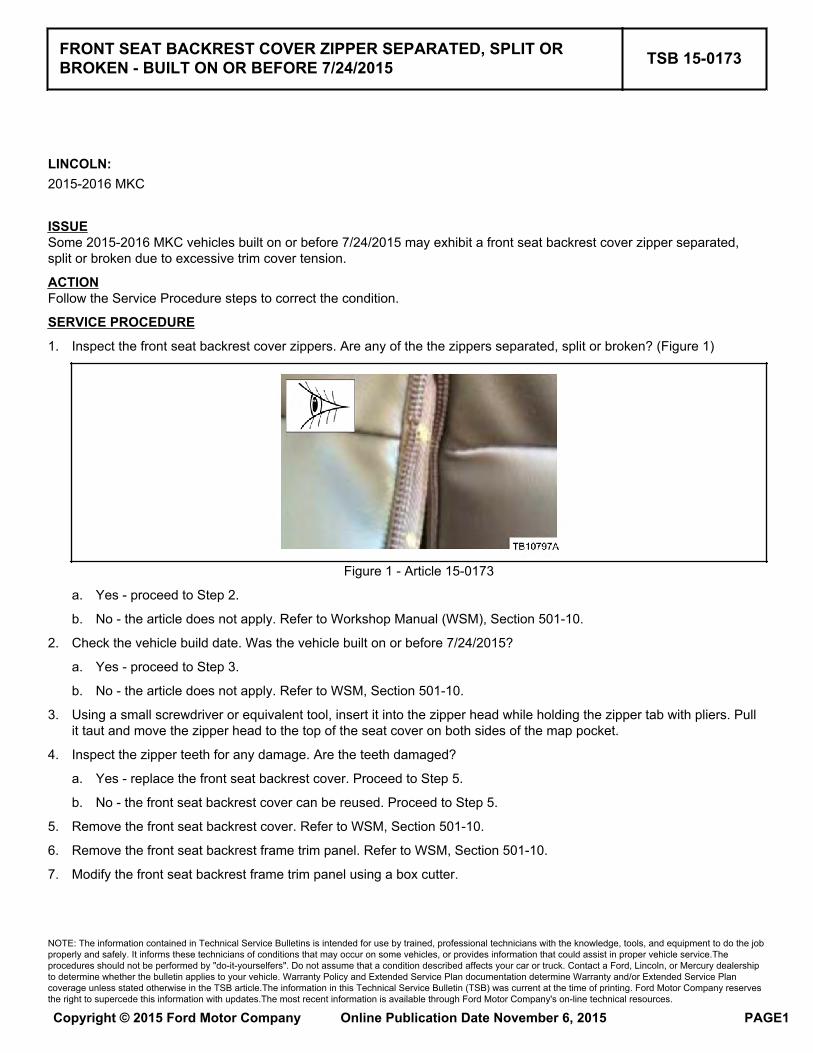
1. Inspect the front seat backrest cover zippers. Are any of the the zippers separated, split or broken? (Figure 1)
Figure 1 - Article 15-0173
a. Yes - proceed to Step 2.
b. No - the article does not apply. Refer to Workshop Manual (WSM), Section 501-10.
2. Check the vehicle build date. Was the vehicle built on or before 7/24/2015?
a. Yes - proceed to Step 3.
b. No - the article does not apply. Refer to WSM, Section 501-10.
3. Using a small screwdriver or equivalent tool, insert it into the zipper head while holding the zipper tab with pliers. Pullit taut and move the zipper head to the top of the seat cover on both sides of the map pocket.
4. Inspect the zipper teeth for any damage. Are the teeth damaged?
a. Yes - replace the front seat backrest cover. Proceed to Step 5.
b. No - the front seat backrest cover can be reused. Proceed to Step 5.
5. Remove the front seat backrest cover. Refer to WSM, Section 501-10.
6. Remove the front seat backrest frame trim panel. Refer to WSM, Section 501-10.
7. Modify the front seat backrest frame trim panel using a box cutter.
FRONT SEAT BACKREST COVER ZIPPER SEPARATED, SPLIT ORBROKEN - BUILT ON OR BEFORE 7/24/2015 TSB 15-0173
NOTE: The information contained in Technical Service Bulletins is intended for use by trained, professional technicians with the knowledge, tools, and equipment to do the jobproperly and safely. It informs these technicians of conditions that may occur on some vehicles, or provides information that could assist in proper vehicle service.Theprocedures should not be performed by "do-it-yourselfers". Do not assume that a condition described affects your car or truck. Contact a Ford, Lincoln, or Mercury dealershipto determine whether the bulletin applies to your vehicle. Warranty Policy and Extended Service Plan documentation determine Warranty and/or Extended Service Plancoverage unless stated otherwise in the TSB article.The information in this Technical Service Bulletin (TSB) was current at the time of printing. Ford Motor Company reservesthe right to supercede this information with updates.The most recent information is available through Ford Motor Company's on-line technical resources.
Copyright © 2015 Ford Motor Company Online Publication Date November 6, 2015 PAGE1
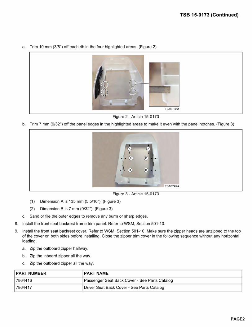
a. Trim 10 mm (3/8") off each rib in the four highlighted areas. (Figure 2)
Figure 2 - Article 15-0173
b. Trim 7 mm (9/32") off the panel edges in the highlighted areas to make it even with the panel notches. (Figure 3)
Figure 3 - Article 15-0173
(1) Dimension A is 135 mm (5 5/16"). (Figure 3)
(2) Dimension B is 7 mm (9/32"). (Figure 3)
c. Sand or file the outer edges to remove any burrs or sharp edges.
8. Install the front seat backrest frame trim panel. Refer to WSM, Section 501-10.
9. Install the front seat backrest cover. Refer to WSM, Section 501-10. Make sure the zipper heads are unzipped to the topof the cover on both sides before installing. Close the zipper trim cover in the following sequence without any horizontalloading.
a. Zip the outboard zipper halfway.
b. Zip the inboard zipper all the way.
c. Zip the outboard zipper all the way.
PART NUMBER PART NAME7864416 Passenger Seat Back Cover - See Parts Catalog
7864417 Driver Seat Back Cover - See Parts Catalog
TSB 15-0173 (Continued)
PAGE2
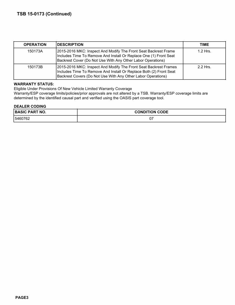
OPERATION DESCRIPTION TIME150173A 2015-2016 MKC: Inspect And Modify The Front Seat Backrest Frame
Includes Time To Remove And Install Or Replace One (1) Front SeatBackrest Cover (Do Not Use With Any Other Labor Operations)
1.2 Hrs.
150173B 2015-2016 MKC: Inspect And Modify The Front Seat Backrest FramesIncludes Time To Remove And Install Or Replace Both (2) Front SeatBackrest Covers (Do Not Use With Any Other Labor Operations)
2.2 Hrs.
WARRANTY STATUS:Eligible Under Provisions Of New Vehicle Limited Warranty CoverageWarranty/ESP coverage limits/policies/prior approvals are not altered by a TSB. Warranty/ESP coverage limits aredetermined by the identified causal part and verified using the OASIS part coverage tool.
DEALER CODINGBASIC PART NO. CONDITION CODE5460762 07
TSB 15-0173 (Continued)
PAGE3
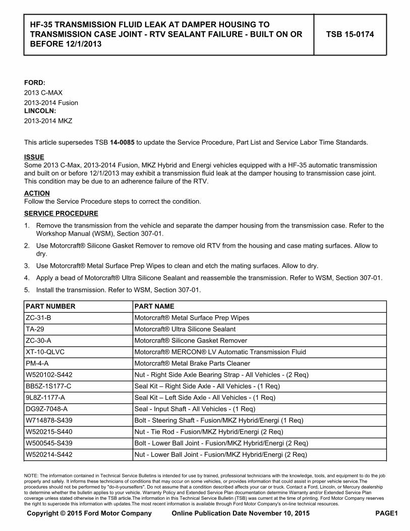
FORD:2013 C-MAX2013-2014 FusionLINCOLN:2013-2014 MKZ
This article supersedes TSB 14-0085 to update the Service Procedure, Part List and Service Labor Time Standards.
ISSUESome 2013 C-Max, 2013-2014 Fusion, MKZ Hybrid and Energi vehicles equipped with a HF-35 automatic transmissionand built on or before 12/1/2013 may exhibit a transmission fluid leak at the damper housing to transmission case joint.This condition may be due to an adherence failure of the RTV.
ACTIONFollow the Service Procedure steps to correct the condition.
SERVICE PROCEDURE
1. Remove the transmission from the vehicle and separate the damper housing from the transmission case. Refer to theWorkshop Manual (WSM), Section 307-01.
2. Use Motorcraft® Silicone Gasket Remover to remove old RTV from the housing and case mating surfaces. Allow todry.
3. Use Motorcraft® Metal Surface Prep Wipes to clean and etch the mating surfaces. Allow to dry.
4. Apply a bead of Motorcraft® Ultra Silicone Sealant and reassemble the transmission. Refer to WSM, Section 307-01.
5. Install the transmission. Refer to WSM, Section 307-01.
PART NUMBER PART NAMEZC-31-B Motorcraft® Metal Surface Prep Wipes
TA-29 Motorcraft® Ultra Silicone Sealant
ZC-30-A Motorcraft® Silicone Gasket Remover
XT-10-QLVC Motorcraft® MERCON® LV Automatic Transmission Fluid
PM-4-A Motorcraft® Metal Brake Parts Cleaner
W520102-S442 Nut - Right Side Axle Bearing Strap - All Vehicles - (2 Req)
BB5Z-1S177-C Seal Kit – Right Side Axle - All Vehicles - (1 Req)
9L8Z-1177-A Seal Kit – Left Side Axle - All Vehicles - (1 Req)
DG9Z-7048-A Seal - Input Shaft - All Vehicles - (1 Req)
W714878-S439 Bolt - Steering Shaft - Fusion/MKZ Hybrid/Energi (1 Req)
W520215-S440 Nut - Tie Rod - Fusion/MKZ Hybrid/Energi (2 Req)
W500545-S439 Bolt - Lower Ball Joint - Fusion/MKZ Hybrid/Energi (2 Req)
W520214-S442 Nut - Lower Ball Joint - Fusion/MKZ Hybrid/Energi (2 Req)
HF-35 TRANSMISSION FLUID LEAK AT DAMPER HOUSING TOTRANSMISSION CASE JOINT - RTV SEALANT FAILURE - BUILT ON ORBEFORE 12/1/2013
TSB 15-0174
NOTE: The information contained in Technical Service Bulletins is intended for use by trained, professional technicians with the knowledge, tools, and equipment to do the jobproperly and safely. It informs these technicians of conditions that may occur on some vehicles, or provides information that could assist in proper vehicle service.Theprocedures should not be performed by "do-it-yourselfers". Do not assume that a condition described affects your car or truck. Contact a Ford, Lincoln, or Mercury dealershipto determine whether the bulletin applies to your vehicle. Warranty Policy and Extended Service Plan documentation determine Warranty and/or Extended Service Plancoverage unless stated otherwise in the TSB article.The information in this Technical Service Bulletin (TSB) was current at the time of printing. Ford Motor Company reservesthe right to supercede this information with updates.The most recent information is available through Ford Motor Company's on-line technical resources.
Copyright © 2015 Ford Motor Company Online Publication Date November 10, 2015 PAGE1
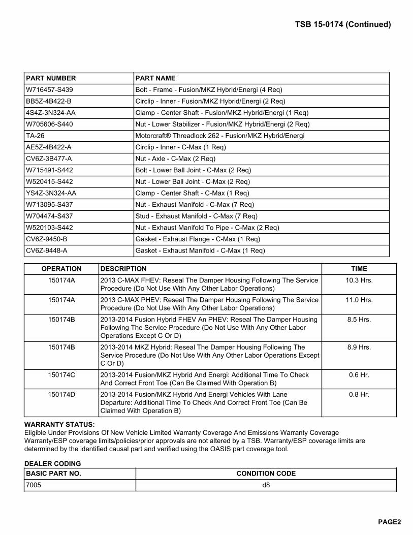
PART NUMBER PART NAMEW716457-S439 Bolt - Frame - Fusion/MKZ Hybrid/Energi (4 Req)
BB5Z-4B422-B Circlip - Inner - Fusion/MKZ Hybrid/Energi (2 Req)
4S4Z-3N324-AA Clamp - Center Shaft - Fusion/MKZ Hybrid/Energi (1 Req)
W705606-S440 Nut - Lower Stabilizer - Fusion/MKZ Hybrid/Energi (2 Req)
TA-26 Motorcraft® Threadlock 262 - Fusion/MKZ Hybrid/Energi
AE5Z-4B422-A Circlip - Inner - C-Max (1 Req)
CV6Z-3B477-A Nut - Axle - C-Max (2 Req)
W715491-S442 Bolt - Lower Ball Joint - C-Max (2 Req)
W520415-S442 Nut - Lower Ball Joint - C-Max (2 Req)
YS4Z-3N324-AA Clamp - Center Shaft - C-Max (1 Req)
W713095-S437 Nut - Exhaust Manifold - C-Max (7 Req)
W704474-S437 Stud - Exhaust Manifold - C-Max (7 Req)
W520103-S442 Nut - Exhaust Manifold To Pipe - C-Max (2 Req)
CV6Z-9450-B Gasket - Exhaust Flange - C-Max (1 Req)
CV6Z-9448-A Gasket - Exhaust Manifold - C-Max (1 Req)
OPERATION DESCRIPTION TIME150174A 2013 C-MAX FHEV: Reseal The Damper Housing Following The Service
Procedure (Do Not Use With Any Other Labor Operations)10.3 Hrs.
150174A 2013 C-MAX PHEV: Reseal The Damper Housing Following The ServiceProcedure (Do Not Use With Any Other Labor Operations)
11.0 Hrs.
150174B 2013-2014 Fusion Hybrid FHEV An PHEV: Reseal The Damper HousingFollowing The Service Procedure (Do Not Use With Any Other LaborOperations Except C Or D)
8.5 Hrs.
150174B 2013-2014 MKZ Hybrid: Reseal The Damper Housing Following TheService Procedure (Do Not Use With Any Other Labor Operations ExceptC Or D)
8.9 Hrs.
150174C 2013-2014 Fusion/MKZ Hybrid And Energi: Additional Time To CheckAnd Correct Front Toe (Can Be Claimed With Operation B)
0.6 Hr.
150174D 2013-2014 Fusion/MKZ Hybrid And Energi Vehicles With LaneDeparture: Additional Time To Check And Correct Front Toe (Can BeClaimed With Operation B)
0.8 Hr.
WARRANTY STATUS:Eligible Under Provisions Of New Vehicle Limited Warranty Coverage And Emissions Warranty CoverageWarranty/ESP coverage limits/policies/prior approvals are not altered by a TSB. Warranty/ESP coverage limits aredetermined by the identified causal part and verified using the OASIS part coverage tool.
DEALER CODINGBASIC PART NO. CONDITION CODE7005 d8
TSB 15-0174 (Continued)
PAGE2
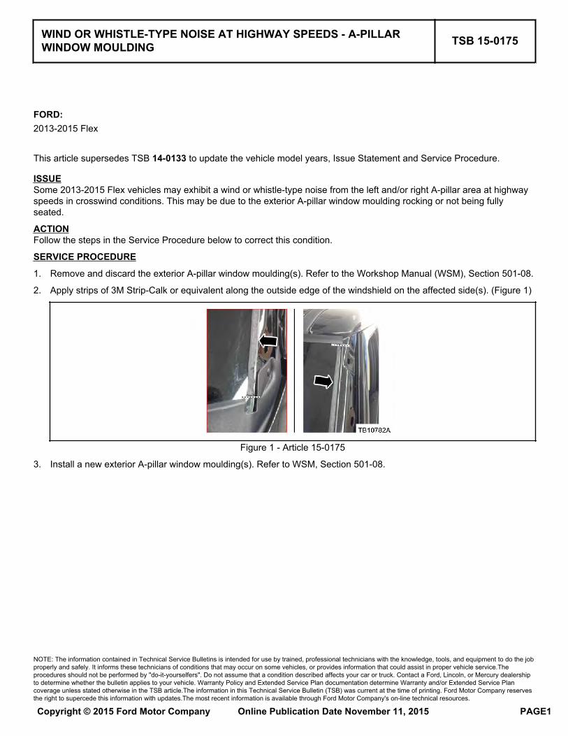
FORD:2013-2015 Flex
This article supersedes TSB 14-0133 to update the vehicle model years, Issue Statement and Service Procedure.
ISSUESome 2013-2015 Flex vehicles may exhibit a wind or whistle-type noise from the left and/or right A-pillar area at highwayspeeds in crosswind conditions. This may be due to the exterior A-pillar window moulding rocking or not being fullyseated.
ACTIONFollow the steps in the Service Procedure below to correct this condition.
SERVICE PROCEDURE
1. Remove and discard the exterior A-pillar window moulding(s). Refer to the Workshop Manual (WSM), Section 501-08.
2. Apply strips of 3M Strip-Calk or equivalent along the outside edge of the windshield on the affected side(s). (Figure 1)
Figure 1 - Article 15-0175
3. Install a new exterior A-pillar window moulding(s). Refer to WSM, Section 501-08.
WIND OR WHISTLE-TYPE NOISE AT HIGHWAY SPEEDS - A-PILLARWINDOW MOULDING TSB 15-0175
NOTE: The information contained in Technical Service Bulletins is intended for use by trained, professional technicians with the knowledge, tools, and equipment to do the jobproperly and safely. It informs these technicians of conditions that may occur on some vehicles, or provides information that could assist in proper vehicle service.Theprocedures should not be performed by "do-it-yourselfers". Do not assume that a condition described affects your car or truck. Contact a Ford, Lincoln, or Mercury dealershipto determine whether the bulletin applies to your vehicle. Warranty Policy and Extended Service Plan documentation determine Warranty and/or Extended Service Plancoverage unless stated otherwise in the TSB article.The information in this Technical Service Bulletin (TSB) was current at the time of printing. Ford Motor Company reservesthe right to supercede this information with updates.The most recent information is available through Ford Motor Company's on-line technical resources.
Copyright © 2015 Ford Motor Company Online Publication Date November 11, 2015 PAGE1
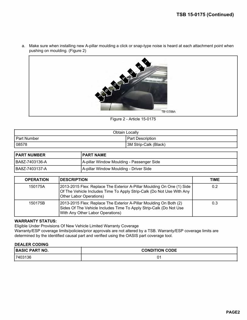
a. Make sure when installing new A-pillar moulding a click or snap-type noise is heard at each attachment point whenpushing on moulding. (Figure 2)
Figure 2 - Article 15-0175
Obtain LocallyPart Number Part Description08578 3M Strip-Calk (Black)
PART NUMBER PART NAMEBA8Z-7403136-A A-pillar Window Moulding - Passenger Side
BA8Z-7403137-A A-pillar Window Moulding - Driver Side
OPERATION DESCRIPTION TIME150175A 2013-2015 Flex: Replace The Exterior A-Pillar Moulding On One (1) Side
Of The Vehicle Includes Time To Apply Strip-Calk (Do Not Use With AnyOther Labor Operations)
0.2
150175B 2013-2015 Flex: Replace The Exterior A-Pillar Moulding On Both (2)Sides Of The Vehicle Includes Time To Apply Strip-Calk (Do Not UseWith Any Other Labor Operations)
0.3
WARRANTY STATUS:Eligible Under Provisions Of New Vehicle Limited Warranty CoverageWarranty/ESP coverage limits/policies/prior approvals are not altered by a TSB. Warranty/ESP coverage limits aredetermined by the identified causal part and verified using the OASIS part coverage tool.
DEALER CODINGBASIC PART NO. CONDITION CODE7403136 01
TSB 15-0175 (Continued)
PAGE2
FORD:2015 Focus
ISSUESome 2015 Focus vehicles equipped with EMTC and built on or before 7/24/2015 may exhibit no airflow through the panelvents when panel/floor mode is selected.
ACTIONFollow the Service Procedure steps to correct the condition.
SERVICE PROCEDURE
1. Check the vehicle build date. Was the vehicle built on or before 7/24/2015 and equipped with a 1.0L gasolineturbocharged direct injected (GTDI) engine?
a. Yes - reprogram the heating ventilation air conditioning (HVAC) module using IDS release 97.02 or higher. Makesure you are connected to the internet when entering module programming to obtain the latest updates.Calibration files may also be obtained at www.motorcraftservice.com.
b. No - proceed to Step 2.
2. Was the vehicle built on or before 7/24/2015 and equipped with a 2.0L gasoline direct injected (GDI) engine or 2.0LGTDI engine?
a. Yes - replace the HVAC control module. Refer to Workshop Manual (WSM), Section 412-00.
b. No - this article does not apply. Refer to WSM, Section 412-00.
PART NUMBER PART NAMEF1EZ-19980-T HVAC Control Module - Without Heated Seats
F1EZ-19980-U HVAC Control Module - With Heated Seats
OPERATION DESCRIPTION TIME150176A 2015 Focus 1.0L GTDI: Reprogram The HVAC Module (Do Not Use
With Any Other Labor Operations)0.3 Hr.
150176A 2015 Focus 2.0L: Replace The HVAC Module (Do Not Use With AnyOther Labor Operations)
0.5 Hr.
WARRANTY STATUS:Eligible Under Provisions Of New Vehicle Limited Warranty CoverageWarranty/ESP coverage limits/policies/prior approvals are not altered by a TSB. Warranty/ESP coverage limits aredetermined by the identified causal part and verified using the OASIS part coverage tool.
DEALER CODINGBASIC PART NO. CONDITION CODE19980 42
ELECTRONIC MANUAL TEMPERATURE CONTROL (EMTC) - NOAIRFLOW FROM PANEL VENTS WHEN PANEL/FLOOR MODESELECTED - BUILT ON OR BEFORE 7/24/2015
TSB 15-0176
NOTE: The information contained in Technical Service Bulletins is intended for use by trained, professional technicians with the knowledge, tools, and equipment to do the jobproperly and safely. It informs these technicians of conditions that may occur on some vehicles, or provides information that could assist in proper vehicle service.Theprocedures should not be performed by "do-it-yourselfers". Do not assume that a condition described affects your car or truck. Contact a Ford, Lincoln, or Mercury dealershipto determine whether the bulletin applies to your vehicle. Warranty Policy and Extended Service Plan documentation determine Warranty and/or Extended Service Plancoverage unless stated otherwise in the TSB article.The information in this Technical Service Bulletin (TSB) was current at the time of printing. Ford Motor Company reservesthe right to supercede this information with updates.The most recent information is available through Ford Motor Company's on-line technical resources.
Copyright © 2015 Ford Motor Company Online Publication Date November 17, 2015 PAGE1
FORD:2013-2014 FusionLINCOLN:2013-2014 MKZ
This article supersedes TSB 14-0099 to update the Part List, Service Procedure and Service Labor Time Standards.
ISSUESome 2013-2014 Fusion and MKZ vehicles built on or before 2/24/2014 may exhibit a musty or organic-type odor from thefront vents when air conditioning (A/C) is activated.
ACTIONFollow the Service Procedure steps to correct the condition.
SERVICE PROCEDURE
1. Replace the Climate Control Housing which includes a revised evaporator core coating. Refer to Workshop Manual(WSM), Section 412-00.
a. Transfer the components from the old housing to the new housing as needed.
PART NUMBER PART NAMEEG9Z-19B555-C Climate Control Housing - Manual Air Conditioning
EG9Z-19B555-D Climate Control Housing - Dual Zone Auto Temp Control
W714878-S439 Bolt - Steering Column Shaft-To-Steering Column
W716505-S422 Bolt - Steering Column (1 Pkg)
W715667-S439 Clip - A-Pillar 2-Stage (1 Pkg)
OPERATION DESCRIPTION TIME150177A 2013-2014 Fusion: Replace The Climate Control Housing (Do Not Use
With Any Other Labor Operations)6.4 Hrs.
150177A 2013-2014 Fusion Hybrid: Replace The Climate Control Housing (DoNot Use With Any Other Labor Operations)
6.8 Hrs.
150177A 2013-2014 Fusion Hybrid Plug In: Replace The Climate ControlHousing (Do Not Use With Any Other Labor Operations)
7.0 Hrs.
150177A 2013-2014 MKZ: Replace The Climate Control Housing (Do Not UseWith Any Other Labor Operations)
7.4 Hrs.
150177A 2013-2014 MKZ Hybrid: Replace The Climate Control Housing (Do NotUse With Any Other Labor Operations)
7.8 Hrs.
WARRANTY STATUS:Eligible Under Provisions Of New Vehicle Limited Warranty CoverageWarranty/ESP coverage limits/policies/prior approvals are not altered by a TSB. Warranty/ESP coverage limits aredetermined by the identified causal part and verified using the OASIS part coverage tool.
MUSTY ODOR FROM A/C VENT ON INITIAL START UP - BUILT ON ORBEFORE 2/24/2014 TSB 15-0177
NOTE: The information contained in Technical Service Bulletins is intended for use by trained, professional technicians with the knowledge, tools, and equipment to do the jobproperly and safely. It informs these technicians of conditions that may occur on some vehicles, or provides information that could assist in proper vehicle service.Theprocedures should not be performed by "do-it-yourselfers". Do not assume that a condition described affects your car or truck. Contact a Ford, Lincoln, or Mercury dealershipto determine whether the bulletin applies to your vehicle. Warranty Policy and Extended Service Plan documentation determine Warranty and/or Extended Service Plancoverage unless stated otherwise in the TSB article.The information in this Technical Service Bulletin (TSB) was current at the time of printing. Ford Motor Company reservesthe right to supercede this information with updates.The most recent information is available through Ford Motor Company's on-line technical resources.
Copyright © 2015 Ford Motor Company Online Publication Date November 18, 2015 PAGE1
DEALER CODINGBASIC PART NO. CONDITION CODE19B555 42
TSB 15-0177 (Continued)
PAGE2
FORD:2012-2014 Edge, Explorer2013-2014 TaurusLINCOLN:2013-2014 MKT
This article supersedes TSB 13-9-8 to update the Service Procedure and Parts List.
ISSUESome 2012-2014 Edge, Explorer and 2013-2014 MKT and Taurus vehicles equipped with a 2.0L Gasoline TurbochargedDirect Injection (GTDI) engine may exhibit difficult to start, runs rough, crank-no start, lack of power, loss of idle RPM orhesitation concerns with diagnostic trouble codes (DTCs) P0106, P0236 or a repeat P0128. These conditions may becaused by a wiring concern in the signal return splice.
ACTIONFollow the Service Procedure Steps to correct the condition.
SERVICE PROCEDURE
1. Using Integrated Diagnostic System (IDS) service tool or equivalent scan tool, check for DTCs.
2. Does the powertrain control module (PCM) only have P0128 DTC stored?
a. No - proceed to Step 4.
b. Yes - proceed to Step 3.
3. Is the coolant level full?
a. No - fill the cooling system using the vacuum cooling system filler procedure. Refer to WSM, Section 303-03.Proceed to Step 4.
b. Yes - proceed to Step 4.
4. Replace the signal return splices using the wire, lead-free solder, heat shrink tubing and instructions supplied in thewire splice solder repair kit.
a. Edge - S176 (YE/GN) and S119 (YE/VT)
b. Explorer - S176 (YE/GN) and S143 (YE/VT)
c. MKT - S112 (YE/GN) and S124 (YE/VT)
d. Taurus - S113 (YE/GN) and S125 (YE/VT)
PART NUMBER PART NAMECU5Z-14A411-A Wire Splice Solder Repair Kit
VC-3DIL-B Motorcraft® Orange Antifreeze/Coolant Prediluted
OPERATION DESCRIPTION TIMEMT150178 Use SLTS Operations If Available; Claim Additional Diagnosis Or Labor
Performed As Actual TimeActual Time
2.0L GTDI ENGINE - DRIVABILITY CONCERNS - DTCS P0106/P0128AND/OR P0236 TSB 15-0178
NOTE: The information contained in Technical Service Bulletins is intended for use by trained, professional technicians with the knowledge, tools, and equipment to do the jobproperly and safely. It informs these technicians of conditions that may occur on some vehicles, or provides information that could assist in proper vehicle service.Theprocedures should not be performed by "do-it-yourselfers". Do not assume that a condition described affects your car or truck. Contact a Ford, Lincoln, or Mercury dealershipto determine whether the bulletin applies to your vehicle. Warranty Policy and Extended Service Plan documentation determine Warranty and/or Extended Service Plancoverage unless stated otherwise in the TSB article.The information in this Technical Service Bulletin (TSB) was current at the time of printing. Ford Motor Company reservesthe right to supercede this information with updates.The most recent information is available through Ford Motor Company's on-line technical resources.
Copyright © 2015 Ford Motor Company Online Publication Date November 20, 2015 PAGE1
WARRANTY STATUS:Eligible Under Provisions Of New Vehicle Limited Warranty Coverage And Emissions Warranty CoverageWarranty/ESP coverage limits/policies/prior approvals are not altered by a TSB. Warranty/ESP coverage limits aredetermined by the identified causal part and verified using the OASIS part coverage tool.
DEALER CODINGBASIC PART NO. CONDITION CODE12A581 28
TSB 15-0178 (Continued)
PAGE2
FORD:2008-2010 E-150, E-250, E-350, F-1502008-2011 Crown Victoria2013-2014 E-150, E-250, E-350LINCOLN:2008 Mark LT2008-2011 Town CarMERCURY:2008-2011 Grand Marquis
This article supersedes TSB 14-0153 to update the vehicle model years and Part List.
ISSUEA service kit has been released to assist with proper repair of the 4R75E transmission in 2008 Mark LT, 2008-2010 F-150,2008-2010 / 2013-2014 E-Series, 2008-2011 Crown Victoria, Grand Marquis and Town Car vehicles that exhibit agrinding, whine-type noise, vibration and/or gear slippage while driving, or a loss of reverse resulting from a planetarygear assembly failure.
ACTIONFollow the Service Procedure steps to correct the condition.
SERVICE PROCEDURE
1. Connect the Ford Integrated Diagnostic System (IDS) or equivalent service tool to the data link connector (DLC).Retrieve all diagnostic trouble codes (DTCs) and record.
a. The following DTCs may be present: P0733, P0720, P0722, P0731, P1783, P0732, P0734, P0721, P0297,P0781, P0782, P1728, P1715, P1744, P1783, P0741, P1741, P1742 and/or P1743.
2. Remove the transmission fluid pan. Refer to Workshop Manual (WSM), Section 307-01.
3. Inspect the transmission fluid pan magnet for debris.
a. If metallic debris is present, proceed to Step 4.
b. If little or no metallic debris is present or if blackened friction material is present, this article does not apply. Referto WSM, Section 307-01 for normal diagnosis.
4. Install transmission fluid pan, remove transmission and disassemble. Refer to WSM, Section 307-01.
a. If cost cap directs transmission repair, proceed to Step 5.
b. If cost cap directs transmission replacement, proceed to Step 10.
5. Clean all internal components thoroughly. Replace any friction material which have metal pieces embedded.
6. Disassemble and clean the main control valve body. Refer to WSM, Section 307-01.
7. Assemble the transmission using the parts provided in the service kit. Be certain to perform steps to determinenumber 1 thrust washer thickness. Refer to WSM, Section 307-01.
a. Service kit contains seals and gaskets for all 4R75 models. Match up all removed seals and gaskets. Some sealsand gaskets in the kit will not be required for certain models. Discard any unused components.
4R75E TRANSMISSION - GRINDING/WHINE/VIBRATION/GEARSLIPPAGE - SERVICE KIT AVAILABLE TSB 15-0179
NOTE: The information contained in Technical Service Bulletins is intended for use by trained, professional technicians with the knowledge, tools, and equipment to do the jobproperly and safely. It informs these technicians of conditions that may occur on some vehicles, or provides information that could assist in proper vehicle service.Theprocedures should not be performed by "do-it-yourselfers". Do not assume that a condition described affects your car or truck. Contact a Ford, Lincoln, or Mercury dealershipto determine whether the bulletin applies to your vehicle. Warranty Policy and Extended Service Plan documentation determine Warranty and/or Extended Service Plancoverage unless stated otherwise in the TSB article.The information in this Technical Service Bulletin (TSB) was current at the time of printing. Ford Motor Company reservesthe right to supercede this information with updates.The most recent information is available through Ford Motor Company's on-line technical resources.
Copyright © 2015 Ford Motor Company Online Publication Date November 23, 2015 PAGE1
8. Were any of the following DTCs present in Step 1: P0741, P1741, P1742, P1743?
a. No - proceed to Step 9.
b. Yes - replace the torque convertor and proceed to Step 10.
9. Place the torque converter assembly on the bench and drain the old fluid. Refill with fresh transmission fluid and drainagain. Repeat until clean oil is present when draining.
10. Perform transmission fluid cooler back flushing and cleaning. Refer to WSM, Section 307-01.
a. The transmission fluid cooler on Crown Victoria, Grand Marquis and Town Car vehicles cannot be flushed due to aninternal thermostatic bypass valve. These vehicles require replacement of the transmission fluid cooler (A/Ccondenser assembly). Refer to WSM, Section 307-02.
11. Install the transmission. Refer to WSM, Section 307-01.
PART NUMBER PART NAMEAL3Z-7A398-C Planetary Upgrade Kit
378941-441 Nut - Converter (4 req.)
56142-S439 Exhaust Bolts - Crown Vic / Grand Mar / Town Car (4 req.)
391188-S441 Exhaust Flange Nuts - Crown Vic / Grand Mar / Town Car (4 req.)
N800594-S100 Driveshaft Fasteners - Except Econoline
N811880-100 Driveshaft Fasteners - Econoline
XL-5 Motorcraft® Multi-Purpose Grease Spray
XG-1-E1 Motorcraft® Premium Long-Life Grease
XT-10-QLVC Motorcraft® MERCON® LV Automatic Transmission Fluid (2009-2012 MY)
XT-5-QM Motorcraft® MERCON® V Automatic Transmission And Power Steering Fluid (2008MY)
TA-25-B Motorcraft® Threadlock and Sealer
XL-12 Motorcraft® Transfer Case Fluid
56761-S439 Bolt - Two Piece Driveshaft - Econoline Center Bearing
W711116-S439 Bolt - 2008 F-150 Multi-piece Driveshaft Center Bearing
7L1Z-4B496-C Front Driveshaft Fasteners - 2009-2010 F-150 4X4 (2 req.)
7L1Z-4B496-D Front Driveshaft Fasteners - 2009-2010 F-150 4X4 (3 req.)
W716375-S900 Transfer Case Bolts - 2009-2010 F-150 4X4 (9 req)
E7TZ-7086-A Gasket - Transfer Case
BW7Z-19712-A A/C Condenser-Cooler - Crown Victoria/Grand Marquis/Town Car
7902 Torque Converter Assembly - See The Dealer Catalog For Proper Replacement Part
7000 Transmission Assembly - See The Dealer Catalog For Proper Replacement Part
OPERATION DESCRIPTION TIME150179A 2008-2011 Crown Victoria, Grand Marquis And Town Car: Check DTCs,
Inspect Fluid Pan, Replace Transmission, Flush Cooler Lines, ReplaceThe Transmission Fluid Cooler Includes Time To Remove And InstallTransmission And Post Road Test (Do Not Use With Any Other LaborOperations Except C When Required)
5.0 Hrs.
TSB 15-0179 (Continued)
PAGE2
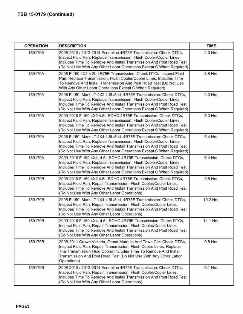
OPERATION DESCRIPTION TIME150179A 2008-2010 / 2013-2014 Econoline 4R75E Transmission: Check DTCs,
Inspect Fluid Pan, Replace Transmission, Flush Cooler/Cooler Lines,Includes Time To Remove And Install Transmission And Post Road Test(Do Not Use With Any Other Labor Operations Except C When Required)
4.3 Hrs.
150179A 2008 F-150 4X2 4.2L 4R75E Transmission: Check DTCs, Inspect FluidPan, Replace Transmission, Flush Cooler/Cooler Lines, Includes TimeTo Remove And Install Transmission And Post Road Test (Do Not UseWith Any Other Labor Operations Except C When Required)
3.8 Hrs.
150179A 2008 F-150, Mark LT 4X2 4.6L/5.4L 4R75E Transmission: Check DTCs,Inspect Fluid Pan, Replace Transmission, Flush Cooler/Cooler Lines,Includes Time To Remove And Install Transmission And Post Road Test(Do Not Use With Any Other Labor Operations Except C When Required)
4.0 Hrs.
150179A 2009-2010 F-150 4X2 4.6L SOHC 4R75E Transmission: Check DTCs,Inspect Fluid Pan, Replace Transmission, Flush Cooler/Cooler Lines,Includes Time To Remove And Install Transmission And Post Road Test(Do Not Use With Any Other Labor Operations Except C When Required)
5.0 Hrs.
150179A 2008 F-150, Mark LT 4X4 4.6L/5.4L 4R75E Transmission: Check DTCs,Inspect Fluid Pan, Replace Transmission, Flush Cooler/Cooler Lines,Includes Time To Remove And Install Transmission And Post Road Test(Do Not Use With Any Other Labor Operations Except C When Required)
5.4 Hrs.
150179A 2009-2010 F-150 4X4, 4.6L SOHC 4R75E Transmission: Check DTCs,Inspect Fluid Pan, Replace Transmission, Flush Cooler/Cooler Lines,Includes Time To Remove And Install Transmission And Post Road Test(Do Not Use With Any Other Labor Operations Except C When Required)
6.4 Hrs.
150179B 2009-2010 F-150 4X2 4.6L SOHC 4R75E Transmission: Check DTCs,Inspect Fluid Pan, Repair Transmission, Flush Cooler/Cooler Lines,Includes Time To Remove And Install Transmission And Post Road Test(Do Not Use With Any Other Labor Operations)
9.8 Hrs.
150179B 2008 F-150, Mark LT 4X4 4.6L/5.4L 4R75E Transmission: Check DTCs,Inspect Fluid Pan, Repair Transmission, Flush Cooler/Cooler Lines,Includes Time To Remove And Install Transmission And Post Road Test(Do Not Use With Any Other Labor Operations)
10.2 Hrs.
150179B 2009-2010 F-150 4X4, 4.6L SOHC 4R75E Transmission: Check DTCs,Inspect Fluid Pan, Repair Transmission, Flush Cooler/Cooler Lines,Includes Time To Remove And Install Transmission And Post Road Test(Do Not Use With Any Other Labor Operations)
11.1 Hrs.
150179B 2008-2011 Crown Victoria, Grand Marquis And Town Car: Check DTCs,Inspect Fluid Pan, Repair Transmission, Flush Cooler Lines, ReplaceThe Transmission Fluid Cooler Includes Time To Remove And InstallTransmission And Post Road Test (Do Not Use With Any Other LaborOperations)
9.8 Hrs.
150179B 2008-2010 / 2013-2014 Econoline 4R75E Transmission: Check DTCs,Inspect Fluid Pan, Repair Transmission, Flush Cooler/Cooler Lines,Includes Time To Remove And Install Transmission And Post Road Test(Do Not Use With Any Other Labor Operations)
9.1 Hrs.
TSB 15-0179 (Continued)
PAGE3
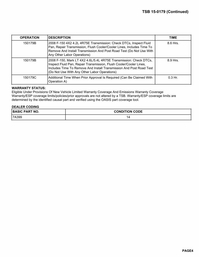
OPERATION DESCRIPTION TIME150179B 2008 F-150 4X2 4.2L 4R75E Transmission: Check DTCs, Inspect Fluid
Pan, Repair Transmission, Flush Cooler/Cooler Lines, Includes Time ToRemove And Install Transmission And Post Road Test (Do Not Use WithAny Other Labor Operations)
8.6 Hrs.
150179B 2008 F-150, Mark LT 4X2 4.6L/5.4L 4R75E Transmission: Check DTCs,Inspect Fluid Pan, Repair Transmission, Flush Cooler/Cooler Lines,Includes Time To Remove And Install Transmission And Post Road Test(Do Not Use With Any Other Labor Operations)
8.9 Hrs.
150179C Additional Time When Prior Approval Is Required (Can Be Claimed WithOperation A)
0.3 Hr.
WARRANTY STATUS:Eligible Under Provisions Of New Vehicle Limited Warranty Coverage And Emissions Warranty CoverageWarranty/ESP coverage limits/policies/prior approvals are not altered by a TSB. Warranty/ESP coverage limits aredetermined by the identified causal part and verified using the OASIS part coverage tool.
DEALER CODINGBASIC PART NO. CONDITION CODE7A399 14
TSB 15-0179 (Continued)
PAGE4
FORD:2016 F-650, F-750
ISSUESome 2016 F-Super Duty 650/750 vehicles equipped with a 6.8L engine may exhibit an inoperative PTO due to wiringcircuit CE326 being installed in the incorrect powertrain control module (PCM) connector cavity of C175B.
ACTIONFollow the Service Procedure steps to correct the condition.
SERVICE PROCEDURE
1. Check the vehicle build date. Was the vehicle built on or before 10/22/2015?
a. Yes - proceed to Step 2.
b. No - this article does not apply. Refer to Powertrain Control/Emissions Diagnosis (PC/ED) manual for PTOControls Diagnostics or the Truck Body Builders Advisory Service website, the Body Builders Layout Book or theSpecial Vehicle Engineering Quality Bulletin Index for the latest information on Stationary SEIC operation.
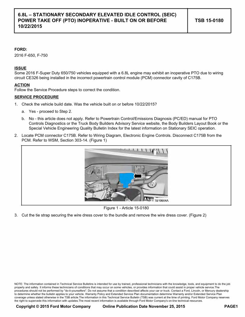
2. Locate PCM connector C175B. Refer to Wiring Diagram, Electronic Engine Controls. Disconnect C175B from thePCM. Refer to WSM, Section 303-14. (Figure 1)
Figure 1 - Article 15-0180
3. Cut the tie strap securing the wire dress cover to the bundle and remove the wire dress cover. (Figure 2)
6.8L – STATIONARY SECONDARY ELEVATED IDLE CONTROL (SEIC)POWER TAKE OFF (PTO) INOPERATIVE - BUILT ON OR BEFORE10/22/2015
TSB 15-0180
NOTE: The information contained in Technical Service Bulletins is intended for use by trained, professional technicians with the knowledge, tools, and equipment to do the jobproperly and safely. It informs these technicians of conditions that may occur on some vehicles, or provides information that could assist in proper vehicle service.Theprocedures should not be performed by "do-it-yourselfers". Do not assume that a condition described affects your car or truck. Contact a Ford, Lincoln, or Mercury dealershipto determine whether the bulletin applies to your vehicle. Warranty Policy and Extended Service Plan documentation determine Warranty and/or Extended Service Plancoverage unless stated otherwise in the TSB article.The information in this Technical Service Bulletin (TSB) was current at the time of printing. Ford Motor Company reservesthe right to supercede this information with updates.The most recent information is available through Ford Motor Company's on-line technical resources.
Copyright © 2015 Ford Motor Company Online Publication Date November 25, 2015 PAGE1
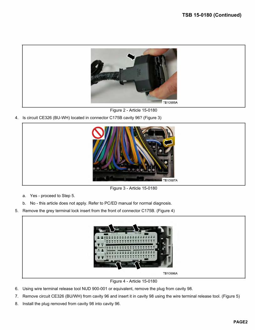
Figure 2 - Article 15-0180
4. Is circuit CE326 (BU-WH) located in connector C175B cavity 96? (Figure 3)
Figure 3 - Article 15-0180
a. Yes - proceed to Step 5.
b. No - this article does not apply. Refer to PC/ED manual for normal diagnosis.
5. Remove the grey terminal lock insert from the front of connector C175B. (Figure 4)
Figure 4 - Article 15-0180
6. Using wire terminal release tool NUD 900-001 or equivalent, remove the plug from cavity 98.
7. Remove circuit CE326 (BU/WH) from cavity 96 and insert it in cavity 98 using the wire terminal release tool. (Figure 5)
8. Install the plug removed from cavity 98 into cavity 96.
TSB 15-0180 (Continued)
PAGE2
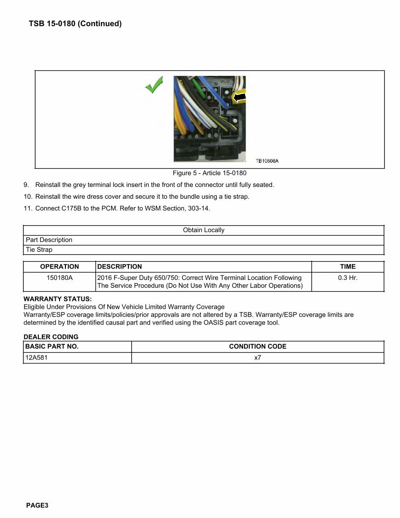
Figure 5 - Article 15-0180
9. Reinstall the grey terminal lock insert in the front of the connector until fully seated.
10. Reinstall the wire dress cover and secure it to the bundle using a tie strap.
11. Connect C175B to the PCM. Refer to WSM Section, 303-14.
Obtain LocallyPart DescriptionTie Strap
OPERATION DESCRIPTION TIME150180A 2016 F-Super Duty 650/750: Correct Wire Terminal Location Following
The Service Procedure (Do Not Use With Any Other Labor Operations)0.3 Hr.
WARRANTY STATUS:Eligible Under Provisions Of New Vehicle Limited Warranty CoverageWarranty/ESP coverage limits/policies/prior approvals are not altered by a TSB. Warranty/ESP coverage limits aredetermined by the identified causal part and verified using the OASIS part coverage tool.
DEALER CODINGBASIC PART NO. CONDITION CODE12A581 x7
TSB 15-0180 (Continued)
PAGE3
FORD:2013-2016 Fusion
This article supersedes TSB 13-5-18 to remove the production fix date, model line versions, update the vehicle modelyears, Service Procedure and Part List.
ISSUESome 2013-2016 Fusion vehicles may exhibit a concern with the luggage compartment lid not staying open.
ACTIONFollow the Service Procedure steps to correct the condition.
SERVICE PROCEDURE
1. Paint to match the replacement upper and lower torsion bars based on vehicle configuration. Refer to WorkshopManual (WSM), Section 100-01 for exterior color paint code.
2. Remove the two (2) push pin fasteners securing the luggage compartment lid striker trim cover and remove the cover.
3. Remove the spare tire cover.
4. Remove the four (4) cargo net fasteners and the two (2) push pin fasteners securing the luggage compartment trim.Position the right and left side trim aside.
5. Support the luggage compartment lid in the full open position.
6. Remove the nylon tie strap holding the torsion bars.
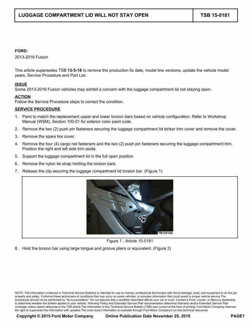
7. Release the clip securing the luggage compartment lid torsion bar. (Figure 1)
Figure 1 - Article 15-0181
8. Hold the torsion bar using large tongue and groove pliers or equivalent. (Figure 2)
LUGGAGE COMPARTMENT LID WILL NOT STAY OPEN TSB 15-0181
NOTE: The information contained in Technical Service Bulletins is intended for use by trained, professional technicians with the knowledge, tools, and equipment to do the jobproperly and safely. It informs these technicians of conditions that may occur on some vehicles, or provides information that could assist in proper vehicle service.Theprocedures should not be performed by "do-it-yourselfers". Do not assume that a condition described affects your car or truck. Contact a Ford, Lincoln, or Mercury dealershipto determine whether the bulletin applies to your vehicle. Warranty Policy and Extended Service Plan documentation determine Warranty and/or Extended Service Plancoverage unless stated otherwise in the TSB article.The information in this Technical Service Bulletin (TSB) was current at the time of printing. Ford Motor Company reservesthe right to supercede this information with updates.The most recent information is available through Ford Motor Company's on-line technical resources.
Copyright © 2015 Ford Motor Company Online Publication Date November 25, 2015 PAGE1
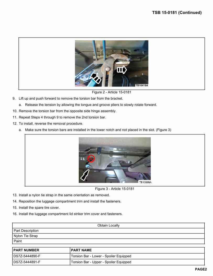
Figure 2 - Article 15-0181
9. Lift up and push forward to remove the torsion bar from the bracket.
a. Release the tension by allowing the tongue and groove pliers to slowly rotate forward.
10. Remove the torsion bar from the opposite side hinge assembly.
11. Repeat Steps 4 through 9 to remove the 2nd torsion bar.
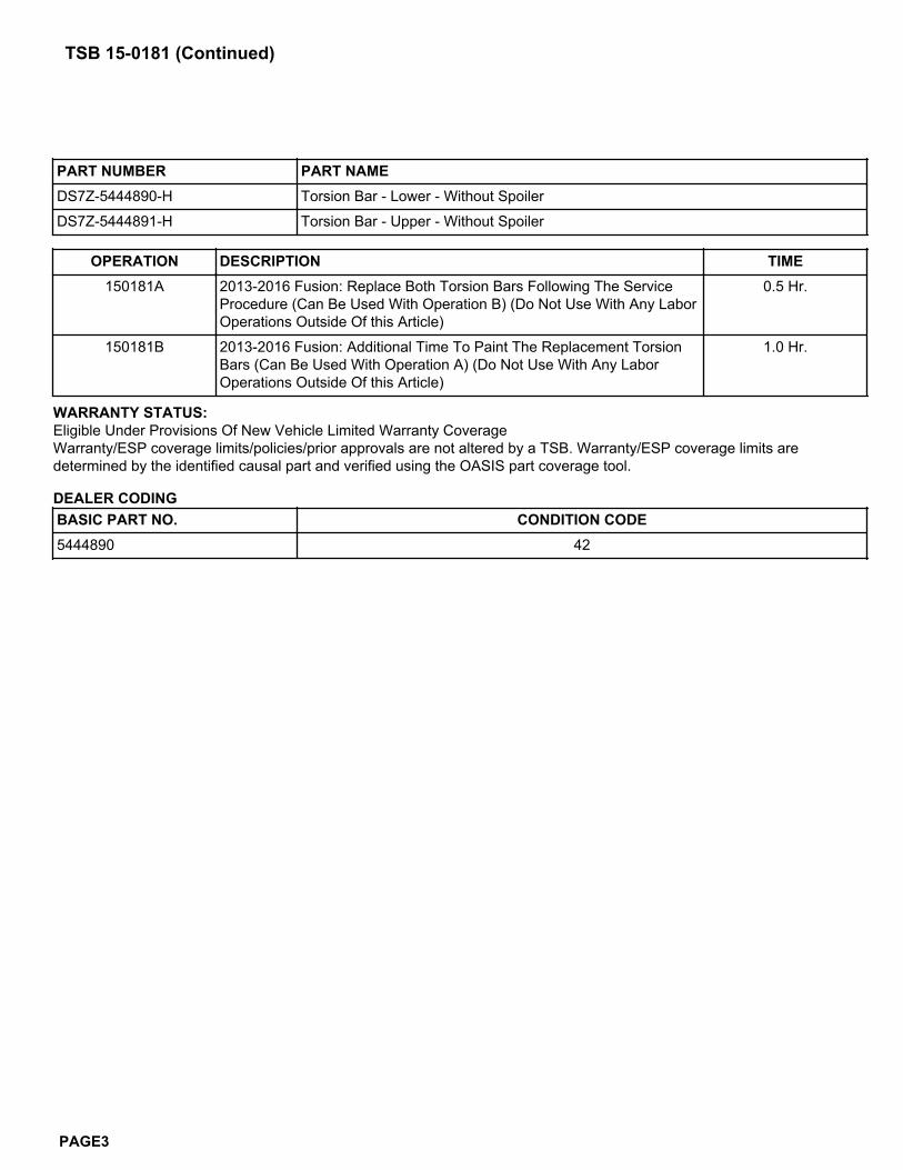
12. To install, reverse the removal procedure.
a. Make sure the torsion bars are installed in the lower notch and not placed in the slot. (Figure 3)
Figure 3 - Article 15-0181
13. Install a nylon tie strap in the same orientation as removed.
14. Reposition the luggage compartment trim and install the fasteners.
15. Install the spare tire cover.
16. Install the luggage compartment lid striker trim cover and fasteners.
Obtain LocallyPart DescriptionNylon Tie StrapPaint
PART NUMBER PART NAMEDS7Z-5444890-F Torsion Bar - Lower - Spoiler Equipped
DS7Z-5444891-F Torsion Bar - Upper - Spoiler Equipped
TSB 15-0181 (Continued)
PAGE2
PART NUMBER PART NAMEDS7Z-5444890-H Torsion Bar - Lower - Without Spoiler
DS7Z-5444891-H Torsion Bar - Upper - Without Spoiler
OPERATION DESCRIPTION TIME150181A 2013-2016 Fusion: Replace Both Torsion Bars Following The Service
Procedure (Can Be Used With Operation B) (Do Not Use With Any LaborOperations Outside Of this Article)
0.5 Hr.
150181B 2013-2016 Fusion: Additional Time To Paint The Replacement TorsionBars (Can Be Used With Operation A) (Do Not Use With Any LaborOperations Outside Of this Article)
1.0 Hr.
WARRANTY STATUS:Eligible Under Provisions Of New Vehicle Limited Warranty CoverageWarranty/ESP coverage limits/policies/prior approvals are not altered by a TSB. Warranty/ESP coverage limits aredetermined by the identified causal part and verified using the OASIS part coverage tool.
DEALER CODINGBASIC PART NO. CONDITION CODE5444890 42
TSB 15-0181 (Continued)
PAGE3
Copyright 2015 Ford Motor Company
Michael A. Berardi Ford Motor Company Director P. O. Box 1904 Service Engineering Operations Dearborn, Michigan 48121 Ford Customer Service Division
November 9, 2015 TO: All U.S. Ford and Lincoln Dealers
SUBJECT: Customer Satisfaction Program 14B07 Certain 2013 through 2014 Model Year C-Max Hybrid and Fusion Hybrid Vehicles Transmission Inspection and Repair
REF :
TSB 14-0214 - HF35 Transmission - Thumping/Rubbing Or Grinding Noise Dated November 13, 2014
PROGRAM TERMS
This program will be in effect through May 31, 2016. There is no mileage limit for this program.
URGENCY / EXPIRATION DATE
This Customer Satisfaction Program has an expiration date of May 31, 2016 to encourage dealers and customers to have this service performed as soon as possible.
We recommend dealers utilize their FSA VIN Lists name and address (available on December 4, 2015) to contact customers with affected vehicles. This will help minimize the number of vehicles that may exhibit transfer shaft gear assembly-to-damper housing contact, which requires a more extensive repair.
AFFECTED VEHICLES
Vehicle Model Year Assembly Plant Build Dates
Fusion Hybrid 2013-2014 Hermosillo November 30, 2012 through January 21, 2014
C-Max Hybrid 2013-2014 Michigan August 8, 2012 through June 17, 2014
Affected vehicles are identified in OASIS and FSA VIN Lists.
REASON FOR THIS PROGRAM
Under certain driving conditions, the transfer shaft gear assembly bearing may fail prematurely. This can result in thumping, rubbing, or grinding noises from the transmission, and may be accompanied by the illumination of the powertrain fault indicator (wrench light) in the instrument cluster.
SERVICE ACTION
Dealers are to disassemble and inspect the transmission for damage or excessive wear, then either repair or replace the transmission as needed. This service must be performed on all affected vehicles at no charge to the vehicle owner.
NOTE: Technical Assistance Center prior approval is not required if the transmission requires replacement under this program.
OWNER NOTIFICATION MAILING SCHEDULE
Owner Letters are expected to be mailed the week of November 16, 2015. Dealers should repair any affected vehicles that arrive at their dealerships, whether or not the customer has received a letter.
Copyright 2015 Ford Motor Company
ATTACHMENTS
Attachment I: Administrative Information Attachment II: Labor Allowances and Parts Ordering Information Attachment III: Technical Information Owner Notification Letter
QUESTIONS & ASSISTANCE
For questions and assistance, contact the Special Service Support Center (SSSC) via the SSSC Web Contact Site. The SSSC Web Contact Site can be accessed through the Professional Technician Society (PTS) website using the SSSC link listed at the bottom of the OASIS VIN report screen or listed under the SSSC tab.
Sincerely,
Michael A. Berardi
Copyright 2015 Ford Motor Company
ATTACHMENT I Page 1 of 2
Customer Satisfaction Program 14B07 Certain 2013 through 2014 Model Year C-Max Hybrid and Fusion Hybrid Vehicles
Transmission Inspection and Repair
OASIS ACTIVATION
OASIS will be activated on November 9, 2015.
FSA VIN LISTS ACTIVATION
FSA VIN Lists will be available through https://web.fsavinlists.dealerconnection.com on November 9, 2015. Owner names and addresses will be available by December 4, 2015.
NOTE: Your FSA VIN Lists may contain owner names and addresses obtained from motor vehicle registration records. The use of such motor vehicle registration data for any purpose other than in connection with this program is a violation of law in several states, provinces, and countries. Accordingly, you must limit the use of this listing to the follow-up necessary to complete this service action.
STOCK VEHICLES
Use OASIS to identify any affected vehicles in your used vehicle inventory.
SOLD VEHICLES
Owners of affected vehicles will be directed to dealers for repairs.
Immediately contact any of your affected customers whose vehicles are not on your VIN list but are identified in OASIS. Give the customer a copy of the Owner Notification Letter (when available) and schedule a service date.
Correct other affected vehicles identified in OASIS which are brought to your dealership.
TITLE BRANDED / SALVAGED VEHICLES
Affected title branded and salvaged vehicles are eligible for this service action.
ADDITIONAL LABOR TIME AND/OR PARTS
Submit a request to the SSSC Web Contact Site prior to the repair if you have any of the following:
Damage that you believe was caused by the covered condition.
A condition that requires additional labor and/or parts to complete the repair.
Aftermarket equipment or non-Ford modifications to the vehicle which might prevent the repair of the covered condition.
Requests for approval after completion of the repair may not be granted. Ford Motor Company reserves the right to deny coverage for related damage in cases where the vehicle owner has not had this recall performed on a timely basis. Additional related damage parts are subject to random selection for return to the Ford Warranty Parts Analysis Center (WPAC).
Copyright 2015 Ford Motor Company
ATTACHMENT I Page 2 of 2
Customer Satisfaction Program 14B07 Certain 2013 through 2014 Model Year C-Max Hybrid and Fusion Hybrid Vehicles
Transmission Inspection and Repair
OWNER REFUNDS
Ford Motor Company is offering a refund for owner-paid repairs covered by this program if the repair was performed before the date of the Owner Notification Letter. This refund offer expires January 31, 2016.
Dealers are also pre-approved to refund owner-paid emergency repairs that were performed away from an authorized servicing dealer after the date of the Owner Notification Letter. There is no expiration date for emergency repair refunds. Non-covered repairs, or those judged by Ford to be excessive, will not be reimbursed.
Refunds will only be provided for the cost associated with transmission replacement caused by transfer shaft gear assembly bearing failure.
RENTAL VEHICLES
If you have a unique circumstance which may require a rental vehicle, please contact the SSSC via the SSSC Web Contact Site.
CLAIMS PREPARATION AND SUBMISSION
Enter claims using Direct Warranty Entry (DWE) or One Warranty Solution (OWS).
o DWE: refer to ACESII manual for claims preparation and submission information.
o OWS: when entering claims in DMS software, select claim type 31: Field Service Action. The FSA number (14B07) is the sub code.
Additional labor and/or parts must be claimed as related damage on a separate repair line from which the FSA is claimed. Additional labor and/or parts require prior approval from the SSSC via the SSSC Web Contact Site.
Submit refunds on a separate repair line.
- Program Code: 14B07 - Misc. Expense: ADMIN
- Misc. Expense: REFUND - Misc. Expense: 0.2 Hrs.
Multiple refunds should be submitted on one repair line and the invoice details for each repair should be detailed in the comments section of the claim.
For rental vehicle claiming, follow Extended Service Plan (ESP) guidelines for dollar amounts. Enter the total amount of the rental expense under Miscellaneous Expense code "Rental".
PROGRAM TERMS: This program will be in effect through May 31, 2016. There is no mileage limit for this program.
Copyright 2015 Ford Motor Company
ATTACHMENT II Page 1 of 4
Customer Satisfaction Program 14B07 Certain 2013 through 2014 Model Year C-Max Hybrid and Fusion Hybrid Vehicles
Transmission Inspection and Repair
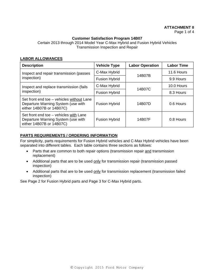
LABOR ALLOWANCES
Description Vehicle Type Labor Operation Labor Time
Inspect and repair transmission (passes inspection)
C-Max Hybrid 14B07B
11.6 Hours
Fusion Hybrid 9.9 Hours
Inspect and replace transmission (fails inspection)
C-Max Hybrid 14B07C
10.0 Hours
Fusion Hybrid 8.3 Hours
Set front end toe – vehicles without Lane Departure Warning System (use with either 14B07B or 14B07C)
Fusion Hybrid 14B07D 0.6 Hours
Set front end toe – vehicles with Lane Departure Warning System (use with either 14B07B or 14B07C)
Fusion Hybrid 14B07F 0.8 Hours
PARTS REQUIREMENTS / ORDERING INFORMATION
For simplicity, parts requirements for Fusion Hybrid vehicles and C-Max Hybrid vehicles have been separated into different tables. Each table contains three sections as follows:
Parts that are common to both repair options (transmission repair and transmission replacement)
Additional parts that are to be used only for transmission repair (transmission passed inspection)
Additional parts that are to be used only for transmission replacement (transmission failed inspection)
See Page 2 for Fusion Hybrid parts and Page 3 for C-Max Hybrid parts.
Copyright 2015 Ford Motor Company
ATTACHMENT II Page 2 of 4
Customer Satisfaction Program 14B07 Certain 2013 through 2014 Model Year C-Max Hybrid and Fusion Hybrid Vehicles
Transmission Inspection and Repair
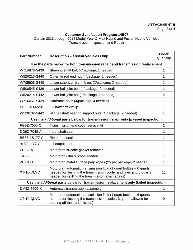
Part Number Description – Fusion Vehicles Only Order
Quantity
Use the parts below for both transmission repair and transmission replacement
W714878-S439 Steering shaft bolt (4/package, 1 needed) 1
W520215-S440 Outer tie rod end nut (4/package, 2 needed) 1
W705606-S440 Lower stabilizer bar link nut (2/package, 2 needed) 1
W500545-S439 Lower ball joint bolt (4/package, 2 needed) 1
W520214-S442 Lower ball joint nut (1/package, 2 needed) 2
W716457-S439 Subframe bolts (4/package, 4 needed) 1
BB5Z-4B422-B LH halfshaft circlip 1
W520102-S442 RH halfshaft bearing support nuts (4/package, 2 needed) 1
Use the additional parts below for transmission repair only (passed inspection)
FG9Z-7000-C Transmission end cover service kit 1
DG9Z-7048-A Input shaft seal 1
BB5Z-1S177-C RH output seal 1
9L8Z-1177-G LH output seal 1
ZC-30-A Motorcraft silicone gasket remover 1
TA-29 Motorcraft ultra silicone sealant 1
ZC-31-B Motorcraft metal surface prep wipes (25 per package, 2 needed) 1
XT-10-QLVC Motorcraft automatic transmission fluid (1 quart bottles – 6 quarts needed for flushing the transmission cooler and lines and 5 quarts needed for refilling the transmission after repairs)
11
Use the additional parts below for transmission replacement only (failed inspection)
DM5Z-7000-K Automatic transmission assembly 1
XT-10-QLVC Motorcraft automatic transmission fluid (1 quart bottles – 6 quarts needed for flushing the transmission cooler, 3 quarts allowed for topping off the transmission)
9
Copyright 2015 Ford Motor Company
ATTACHMENT II Page 3 of 4
Customer Satisfaction Program 14B07 Certain 2013 through 2014 Model Year C-Max Hybrid and Fusion Hybrid Vehicles
Transmission Inspection and Repair
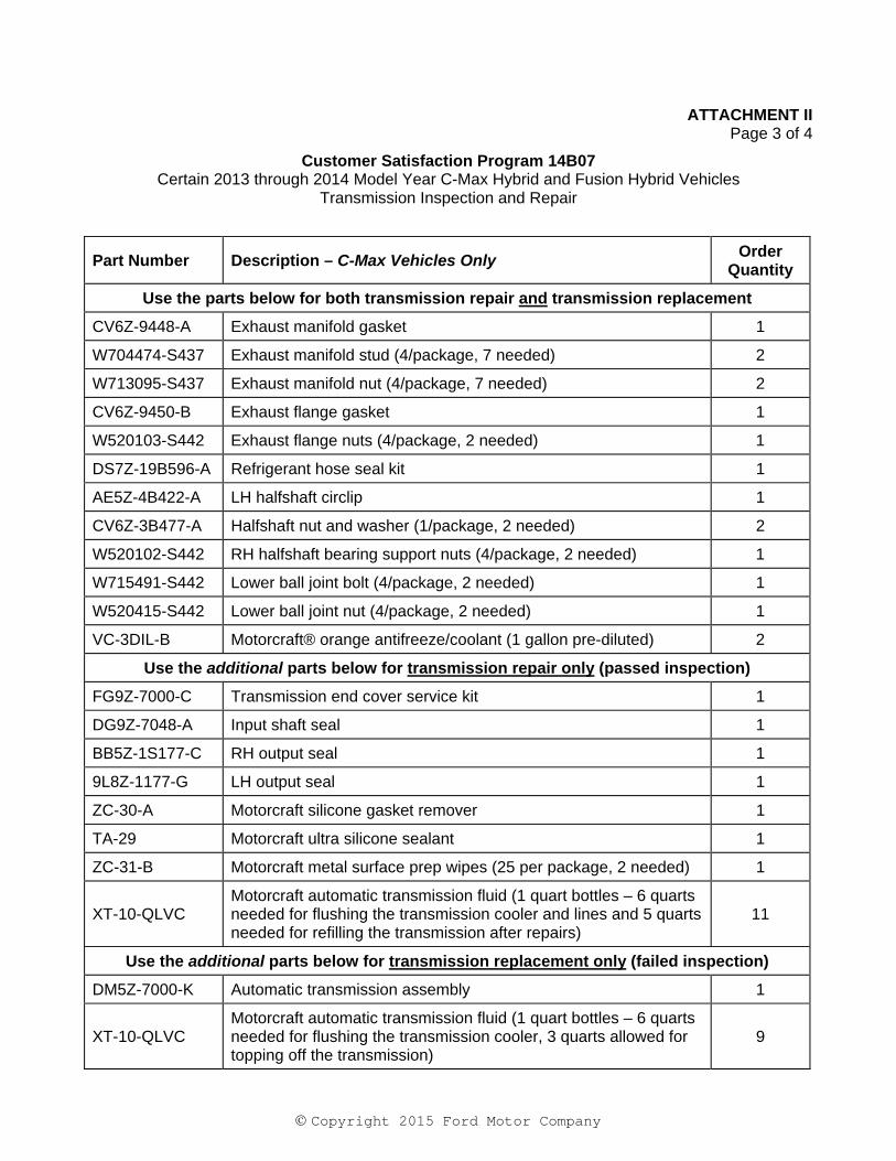
Part Number Description – C-Max Vehicles Only Order
Quantity
Use the parts below for both transmission repair and transmission replacement
CV6Z-9448-A Exhaust manifold gasket 1
W704474-S437 Exhaust manifold stud (4/package, 7 needed) 2
W713095-S437 Exhaust manifold nut (4/package, 7 needed) 2
CV6Z-9450-B Exhaust flange gasket 1
W520103-S442 Exhaust flange nuts (4/package, 2 needed) 1
DS7Z-19B596-A Refrigerant hose seal kit 1
AE5Z-4B422-A LH halfshaft circlip 1
CV6Z-3B477-A Halfshaft nut and washer (1/package, 2 needed) 2
W520102-S442 RH halfshaft bearing support nuts (4/package, 2 needed) 1
W715491-S442 Lower ball joint bolt (4/package, 2 needed) 1
W520415-S442 Lower ball joint nut (4/package, 2 needed) 1
VC-3DIL-B Motorcraft® orange antifreeze/coolant (1 gallon pre-diluted) 2
Use the additional parts below for transmission repair only (passed inspection)
FG9Z-7000-C Transmission end cover service kit 1
DG9Z-7048-A Input shaft seal 1
BB5Z-1S177-C RH output seal 1
9L8Z-1177-G LH output seal 1
ZC-30-A Motorcraft silicone gasket remover 1
TA-29 Motorcraft ultra silicone sealant 1
ZC-31-B Motorcraft metal surface prep wipes (25 per package, 2 needed) 1
XT-10-QLVC Motorcraft automatic transmission fluid (1 quart bottles – 6 quarts needed for flushing the transmission cooler and lines and 5 quarts needed for refilling the transmission after repairs)
11
Use the additional parts below for transmission replacement only (failed inspection)
DM5Z-7000-K Automatic transmission assembly 1
XT-10-QLVC Motorcraft automatic transmission fluid (1 quart bottles – 6 quarts needed for flushing the transmission cooler, 3 quarts allowed for topping off the transmission)
9
Copyright 2015 Ford Motor Company
ATTACHMENT II Page 4 of 4
Customer Satisfaction Program 14B07 Certain 2013 through 2014 Model Year C-Max Hybrid and Fusion Hybrid Vehicles
Transmission Inspection and Repair
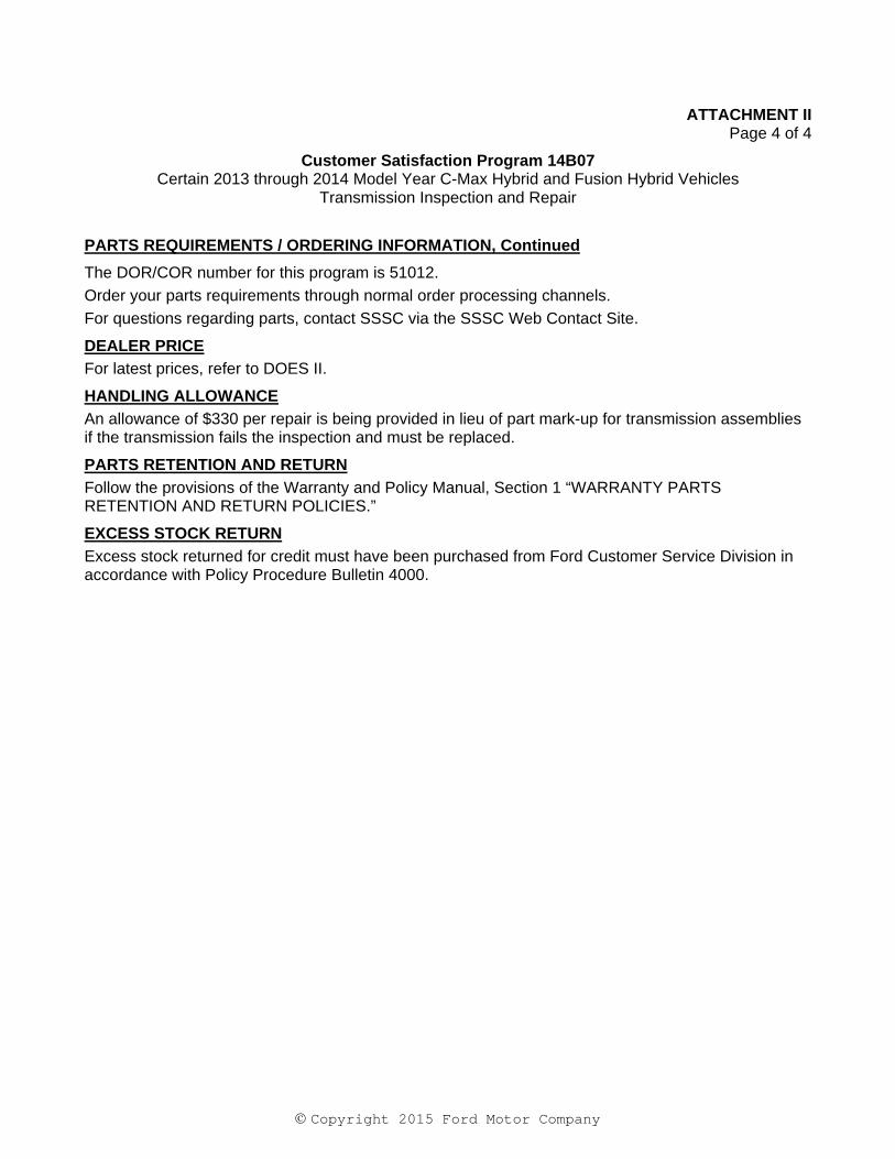
PARTS REQUIREMENTS / ORDERING INFORMATION, Continued
The DOR/COR number for this program is 51012.
Order your parts requirements through normal order processing channels.
For questions regarding parts, contact SSSC via the SSSC Web Contact Site.
DEALER PRICE
For latest prices, refer to DOES II.
HANDLING ALLOWANCE
An allowance of $330 per repair is being provided in lieu of part mark-up for transmission assemblies if the transmission fails the inspection and must be replaced.
PARTS RETENTION AND RETURN
Follow the provisions of the Warranty and Policy Manual, Section 1 “WARRANTY PARTS RETENTION AND RETURN POLICIES.”
EXCESS STOCK RETURN
Excess stock returned for credit must have been purchased from Ford Customer Service Division in accordance with Policy Procedure Bulletin 4000.
ATTACHMENT III PAGE 1 OF 25
CUSTOMER SATISFACTION PROGRAM 14B07
CPR © 2015 FORD MOTOR COMPANYDEARBORN, MICHIGAN 4812111/2015
CERTAIN 2013 - 2014 MODEL YEAR C-MAX HYBRID AND FUSION HYBRID VEHICLES — TRANSMISSION INSPECTION AND REPAIR
OVERVIEW
Under certain driving conditions, the transfer shaft gear assembly bearing may fail prematurely. This can result in thumping, rubbing, or grinding noises from the transmission, and may be accompanied by the illumination of the powertrain fault indicator (wrench light) in the instrument cluster. Dealers are to disassemble and inspect the transmission for damage or excessive wear, then either repair or replace the transmission as needed.
SERVICE PROCEDURE
1. Remove the transmission assembly. Please follow the Workshop Manual (WSM) procedures in Section 307-01.
2. Flush transmission fluid cooling system. Please follow the WSM procedures in Section 307-02.
3. Follow the Transmission - Disassembly and Inspection Procedure starting on Page 2.
- Is contact or wear present on damper housing or any of the gears or bearings? - No - Proceed to Transmission - Repair and Assembly Procedure starting on Page 4. - Yes - Install a new transmission assembly. Please follow the WSM procedures in Section 307-01.
ATTACHMENT III PAGE 2 OF 25
CUSTOMER SATISFACTION PROGRAM 14B07
CPR © 2015 FORD MOTOR COMPANYDEARBORN, MICHIGAN 4812111/2015
E151264
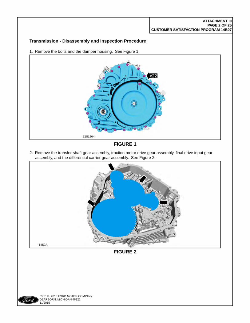
FIGURE 1
Transmission - Disassembly and Inspection Procedure
1. Remove the bolts and the damper housing. See Figure 1.
2. Remove the transfer shaft gear assembly, traction motor drive gear assembly, final drive input gear assembly, and the differential carrier gear assembly. See Figure 2.
1452A
FIGURE 2
ATTACHMENT III PAGE 3 OF 25
CUSTOMER SATISFACTION PROGRAM 14B07
CPR © 2015 FORD MOTOR COMPANYDEARBORN, MICHIGAN 4812111/2015
1452B
PLACE COPY HERE
PLACE COPY HERE
PLACE COPY HERE
PASS INSPECTION
STUD FORMISSING NUT
STUD FORMISSING NUT
PASS INSPECTIONFAIL INSPECTION
FIGURE 3
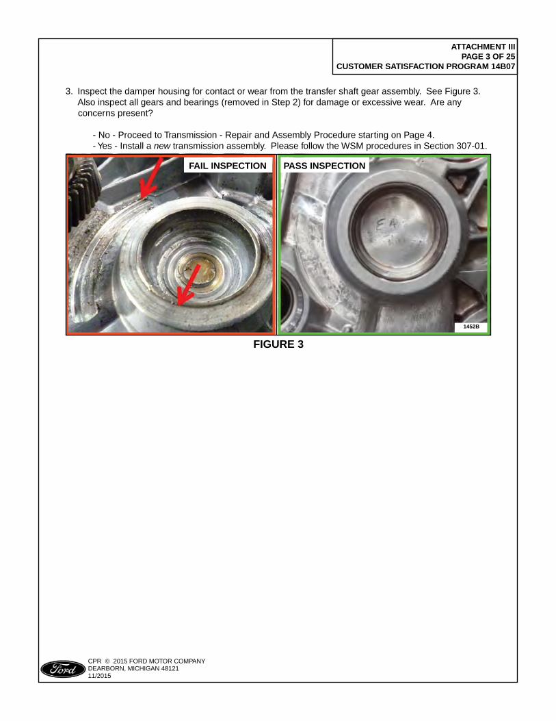
3. Inspect the damper housing for contact or wear from the transfer shaft gear assembly. See Figure 3. Also inspect all gears and bearings (removed in Step 2) for damage or excessive wear. Are any concerns present?
- No - Proceed to Transmission - Repair and Assembly Procedure starting on Page 4. - Yes - Install a new transmission assembly. Please follow the WSM procedures in Section 307-01.
ATTACHMENT III PAGE 4 OF 25
CUSTOMER SATISFACTION PROGRAM 14B07
CPR © 2015 FORD MOTOR COMPANYDEARBORN, MICHIGAN 4812111/2015
Transmission - Repair and Assembly Procedure
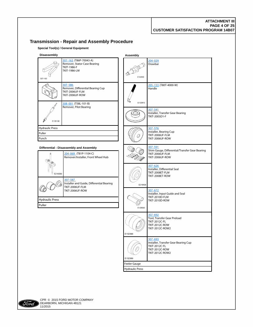
204 -029Drawbar
205 -153 (T80T-4000-W) Handle
307 -541Installer, Transfer Gear BearingTKIT-2005D1-F
307 -576Installer, Bearing CupTKIT-2006UF-FLMTKIT-2006UF-ROW
307 -591Shim Gauge, Di�erential/Transfer Gear BearingTKIT-2006UF-FLMTKIT-2006UF-ROW
307 -626Installer, Di�erential SealTKIT-2008ET-FLMTKIT-2008ET-ROW
307 -672Installer, Input Guide and SealTKIT-2010D-FLMTKIT-2010D-ROW
307 -692Tool, Transfer Gear PreloadTKIT-2012C-FLTKIT-2012C-ROWTKIT-2012C-ROW2
307 -693Installer, Transfer Gear Bearing CupTKIT-2012C-FLTKIT-2012C-ROWTKIT-2012C-ROW2
Feeler Gauge
Hydraulic Press
Special Tool(s) / General Equipment
307 -163 (T86P-70043-A) Remover, Stator Case BearingTKIT-1986-FTKIT-1986-LM
307 -586Remover, Di�erential Bearing CupTKIT-2006UF-FLMTKIT-2006UF-ROW
308 -001 (T58L-101-B) Remover, Pilot Bearing
Hydraulic Press
Puller
Punch
Disassembly Assembly
Differential - Disassembly and Assembly
204 -069 (T81P-1104-C) Remover/Installer, Front Wheel Hub
307 -587Installer and Guide, Di�erential BearingTKIT-2006UF-FLMTKIT-2006UF-ROW
Hydraulic Press
Puller
ATTACHMENT III PAGE 5 OF 25
CUSTOMER SATISFACTION PROGRAM 14B07
CPR © 2015 FORD MOTOR COMPANYDEARBORN, MICHIGAN 4812111/2015
E153250
307-163
308-001
FIGURE 4
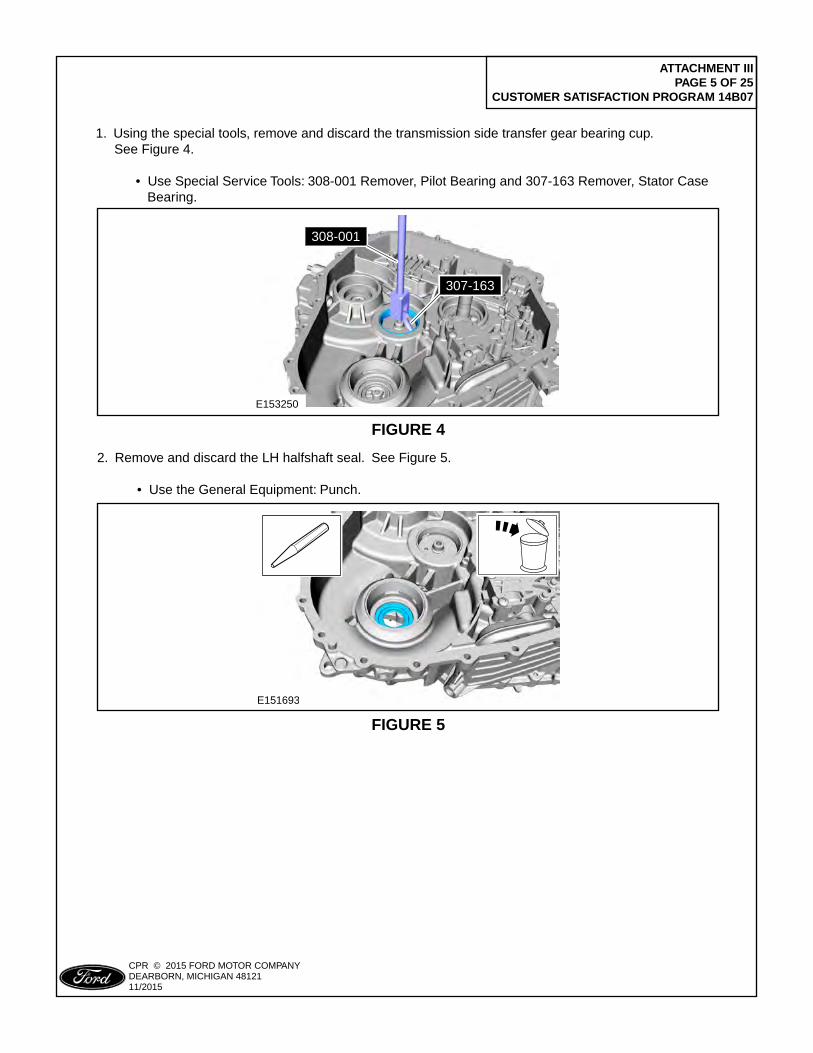
1. Using the special tools, remove and discard the transmission side transfer gear bearing cup. See Figure 4. • Use Special Service Tools: 308-001 Remover, Pilot Bearing and 307-163 Remover, Stator Case Bearing.
E151693
FIGURE 5
2. Remove and discard the LH halfshaft seal. See Figure 5.
• Use the General Equipment: Punch.
ATTACHMENT III PAGE 6 OF 25
CUSTOMER SATISFACTION PROGRAM 14B07
CPR © 2015 FORD MOTOR COMPANYDEARBORN, MICHIGAN 4812111/2015
E151698
x2
FIGURE 6
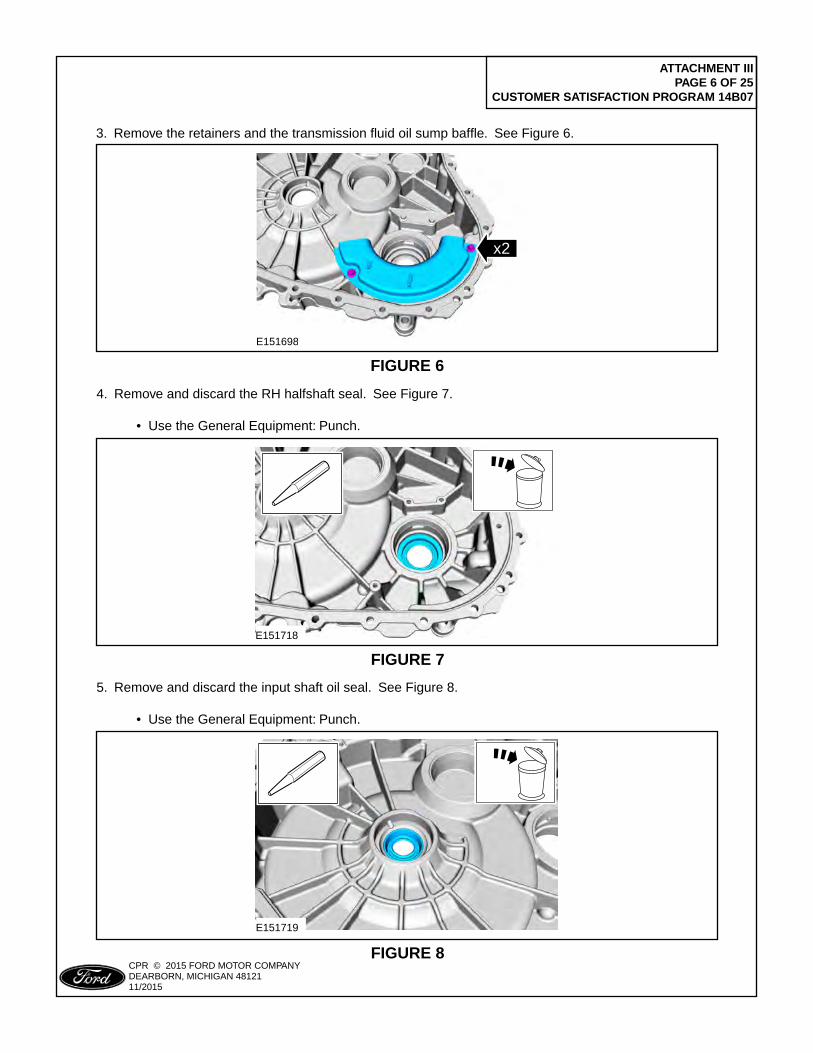
3. Remove the retainers and the transmission fluid oil sump baffle. See Figure 6.
E151718
FIGURE 7
4. Remove and discard the RH halfshaft seal. See Figure 7.
• Use the General Equipment: Punch.
E151719
FIGURE 8
5. Remove and discard the input shaft oil seal. See Figure 8.
• Use the General Equipment: Punch.
ATTACHMENT III PAGE 7 OF 25
CUSTOMER SATISFACTION PROGRAM 14B07
CPR © 2015 FORD MOTOR COMPANYDEARBORN, MICHIGAN 4812111/2015
E151843
308-001
307-163
FIGURE 9
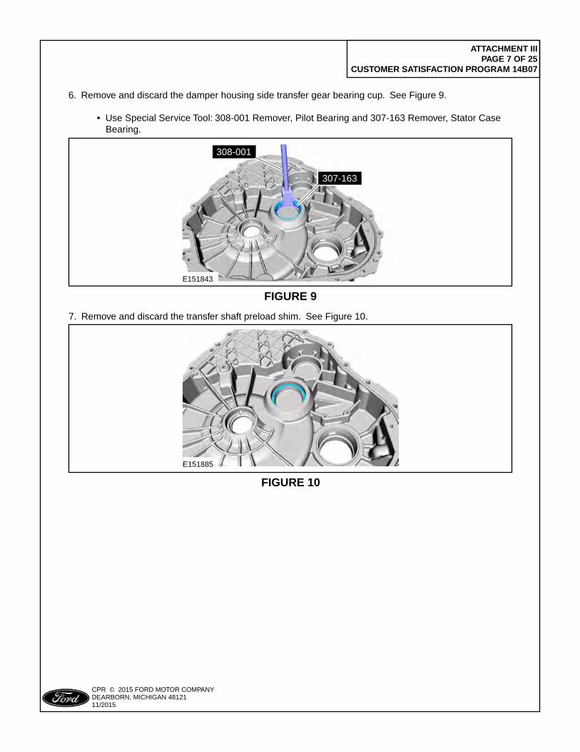
6. Remove and discard the damper housing side transfer gear bearing cup. See Figure 9.
• Use Special Service Tool: 308-001 Remover, Pilot Bearing and 307-163 Remover, Stator Case Bearing.
E151885
FIGURE 10
7. Remove and discard the transfer shaft preload shim. See Figure 10.
ATTACHMENT III PAGE 8 OF 25
CUSTOMER SATISFACTION PROGRAM 14B07
CPR © 2015 FORD MOTOR COMPANYDEARBORN, MICHIGAN 4812111/2015
E151846
307-586
12
3
FIGURE 11
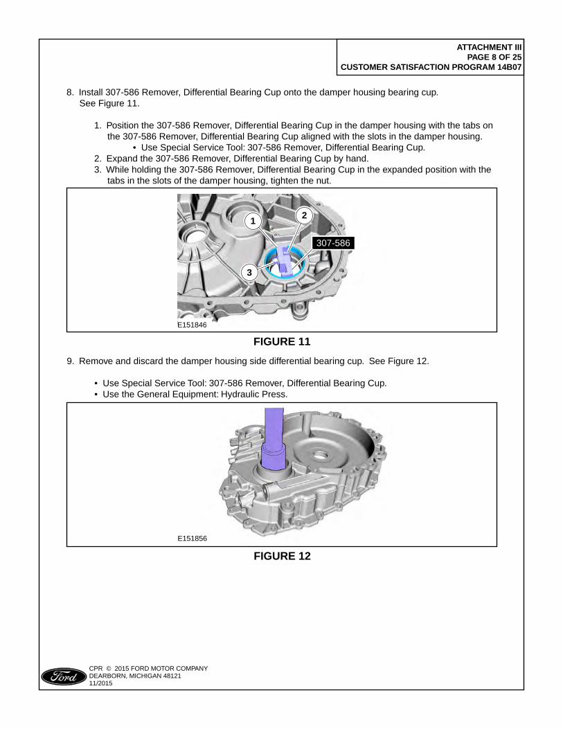
8. Install 307-586 Remover, Differential Bearing Cup onto the damper housing bearing cup. See Figure 11.
1. Position the 307-586 Remover, Differential Bearing Cup in the damper housing with the tabs on the 307-586 Remover, Differential Bearing Cup aligned with the slots in the damper housing. • Use Special Service Tool: 307-586 Remover, Differential Bearing Cup. 2. Expand the 307-586 Remover, Differential Bearing Cup by hand. 3. While holding the 307-586 Remover, Differential Bearing Cup in the expanded position with the tabs in the slots of the damper housing, tighten the nut.
E151856
FIGURE 12
9. Remove and discard the damper housing side differential bearing cup. See Figure 12.
• Use Special Service Tool: 307-586 Remover, Differential Bearing Cup. • Use the General Equipment: Hydraulic Press.
ATTACHMENT III PAGE 9 OF 25
CUSTOMER SATISFACTION PROGRAM 14B07
CPR © 2015 FORD MOTOR COMPANYDEARBORN, MICHIGAN 4812111/2015
E151884
FIGURE 13
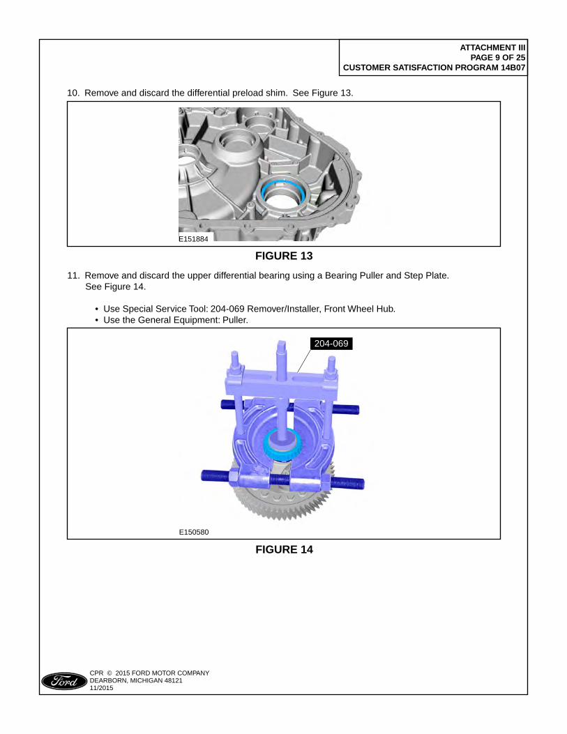
10. Remove and discard the differential preload shim. See Figure 13.
E150580
204-069
FIGURE 14
11. Remove and discard the upper differential bearing using a Bearing Puller and Step Plate. See Figure 14.
• Use Special Service Tool: 204-069 Remover/Installer, Front Wheel Hub. • Use the General Equipment: Puller.
ATTACHMENT III PAGE 10 OF 25
CUSTOMER SATISFACTION PROGRAM 14B07
CPR © 2015 FORD MOTOR COMPANYDEARBORN, MICHIGAN 4812111/2015
307-587/1
307-587/2
307-587/1
307-587/2E150586
FIGURE 15
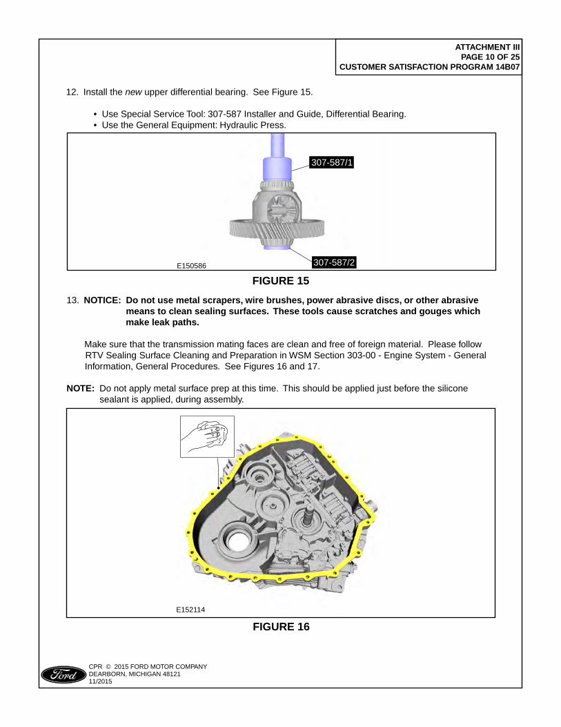
12. Install the new upper differential bearing. See Figure 15.
• Use Special Service Tool: 307-587 Installer and Guide, Differential Bearing. • Use the General Equipment: Hydraulic Press.
E152114
FIGURE 16
13. NOTICE: Do not use metal scrapers, wire brushes, power abrasive discs, or other abrasive means to clean sealing surfaces. These tools cause scratches and gouges which make leak paths.
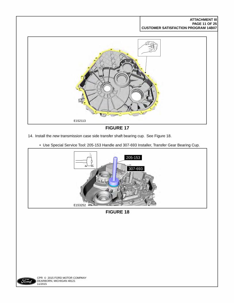
Make sure that the transmission mating faces are clean and free of foreign material. Please follow RTV Sealing Surface Cleaning and Preparation in WSM Section 303-00 - Engine System - General Information, General Procedures. See Figures 16 and 17.
NOTE: Do not apply metal surface prep at this time. This should be applied just before the silicone sealant is applied, during assembly.
ATTACHMENT III PAGE 11 OF 25
CUSTOMER SATISFACTION PROGRAM 14B07
CPR © 2015 FORD MOTOR COMPANYDEARBORN, MICHIGAN 4812111/2015
E152113
FIGURE 17
E153252
307-693
205-153
FIGURE 18
14. Install the new transmission case side transfer shaft bearing cup. See Figure 18. • Use Special Service Tool: 205-153 Handle and 307-693 Installer, Transfer Gear Bearing Cup.
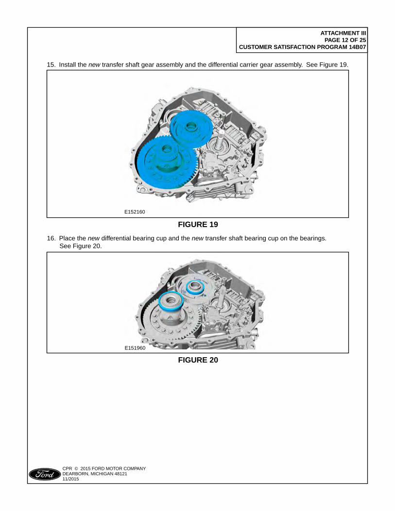
ATTACHMENT III PAGE 12 OF 25
CUSTOMER SATISFACTION PROGRAM 14B07
CPR © 2015 FORD MOTOR COMPANYDEARBORN, MICHIGAN 4812111/2015
E152160
FIGURE 19
15. Install the new transfer shaft gear assembly and the differential carrier gear assembly. See Figure 19.
E151960
FIGURE 20
16. Place the new differential bearing cup and the new transfer shaft bearing cup on the bearings. See Figure 20.
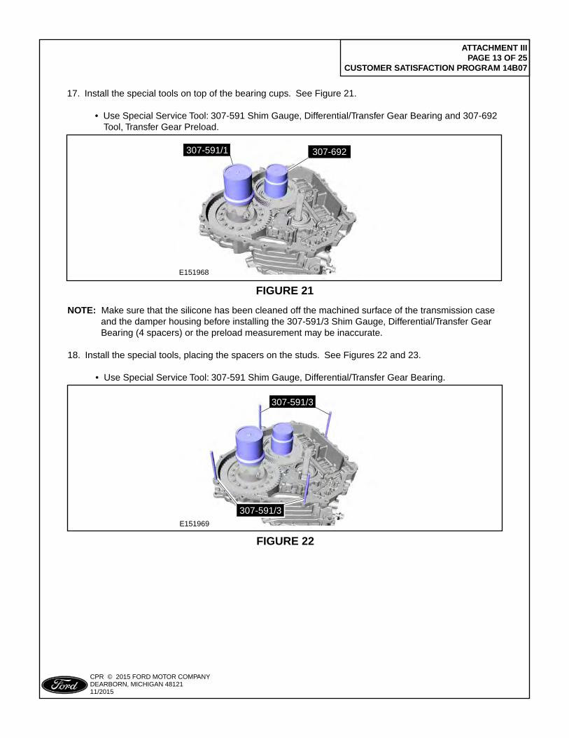
ATTACHMENT III PAGE 13 OF 25
CUSTOMER SATISFACTION PROGRAM 14B07
CPR © 2015 FORD MOTOR COMPANYDEARBORN, MICHIGAN 4812111/2015
E151968
307-692307-591/1
FIGURE 21
17. Install the special tools on top of the bearing cups. See Figure 21.
• Use Special Service Tool: 307-591 Shim Gauge, Differential/Transfer Gear Bearing and 307-692 Tool, Transfer Gear Preload.
E151969
307-591/3
307-591/3
FIGURE 22
NOTE: Make sure that the silicone has been cleaned off the machined surface of the transmission case and the damper housing before installing the 307-591/3 Shim Gauge, Differential/Transfer Gear Bearing (4 spacers) or the preload measurement may be inaccurate.
18. Install the special tools, placing the spacers on the studs. See Figures 22 and 23.
• Use Special Service Tool: 307-591 Shim Gauge, Differential/Transfer Gear Bearing.
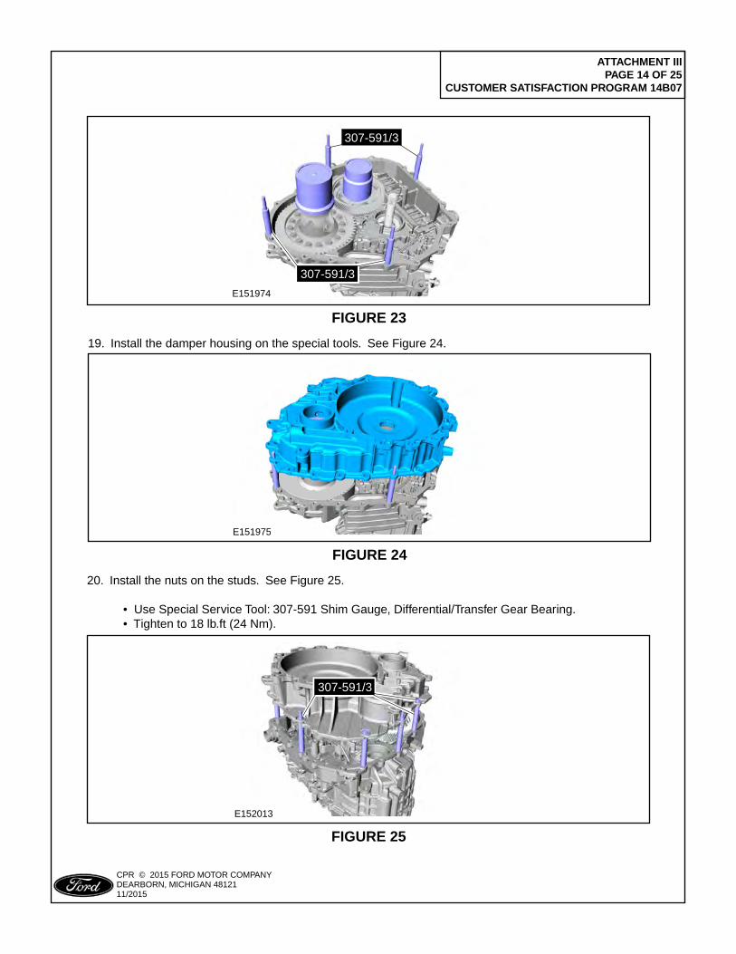
ATTACHMENT III PAGE 14 OF 25
CUSTOMER SATISFACTION PROGRAM 14B07
CPR © 2015 FORD MOTOR COMPANYDEARBORN, MICHIGAN 4812111/2015
E151974
307-591/3
307-591/3
FIGURE 23
E151975
FIGURE 24
19. Install the damper housing on the special tools. See Figure 24.
E152013
307-591/3
FIGURE 25
20. Install the nuts on the studs. See Figure 25.
• Use Special Service Tool: 307-591 Shim Gauge, Differential/Transfer Gear Bearing. • Tighten to 18 lb.ft (24 Nm).
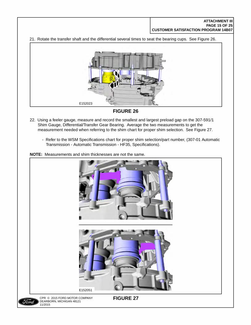
ATTACHMENT III PAGE 15 OF 25
CUSTOMER SATISFACTION PROGRAM 14B07
CPR © 2015 FORD MOTOR COMPANYDEARBORN, MICHIGAN 4812111/2015
E152023
FIGURE 26
21. Rotate the transfer shaft and the differential several times to seat the bearing cups. See Figure 26.
E152051
FIGURE 27
22. Using a feeler gauge, measure and record the smallest and largest preload gap on the 307-591/1 Shim Gauge, Differential/Transfer Gear Bearing. Average the two measurements to get the measurement needed when referring to the shim chart for proper shim selection. See Figure 27.
- Refer to the WSM Specifications chart for proper shim selection/part number, (307-01 Automatic Transmission - Automatic Transmission - HF35, Specifications).
NOTE: Measurements and shim thicknesses are not the same.
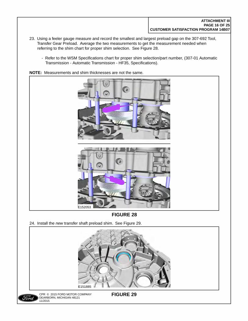
ATTACHMENT III PAGE 16 OF 25
CUSTOMER SATISFACTION PROGRAM 14B07
CPR © 2015 FORD MOTOR COMPANYDEARBORN, MICHIGAN 4812111/2015
E152053
FIGURE 28
23. Using a feeler gauge measure and record the smallest and largest preload gap on the 307-692 Tool, Transfer Gear Preload. Average the two measurements to get the measurement needed when referring to the shim chart for proper shim selection. See Figure 28.
- Refer to the WSM Specifications chart for proper shim selection/part number, (307-01 Automatic Transmission - Automatic Transmission - HF35, Specifications).
NOTE: Measurements and shim thicknesses are not the same.
E151885
FIGURE 29
24. Install the new transfer shaft preload shim. See Figure 29.
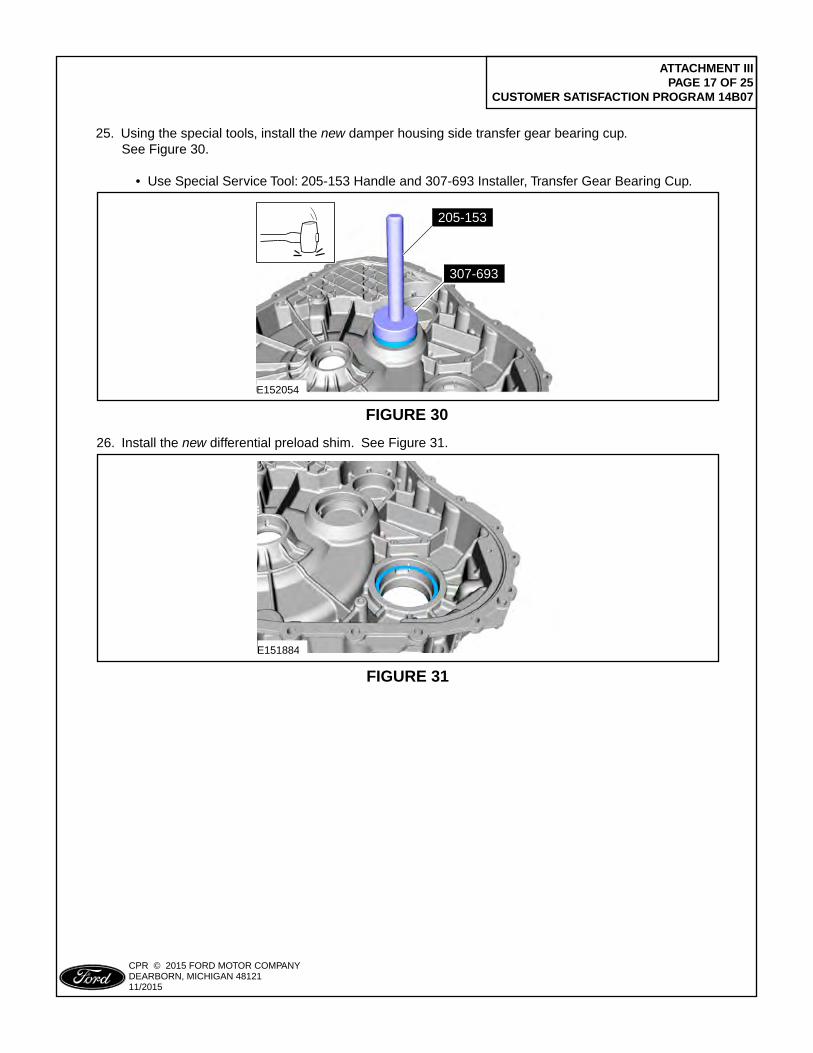
ATTACHMENT III PAGE 17 OF 25
CUSTOMER SATISFACTION PROGRAM 14B07
CPR © 2015 FORD MOTOR COMPANYDEARBORN, MICHIGAN 4812111/2015
E152054
307-693
205-153
FIGURE 30
25. Using the special tools, install the new damper housing side transfer gear bearing cup. See Figure 30.
• Use Special Service Tool: 205-153 Handle and 307-693 Installer, Transfer Gear Bearing Cup.
E151884
FIGURE 31
26. Install the new differential preload shim. See Figure 31.
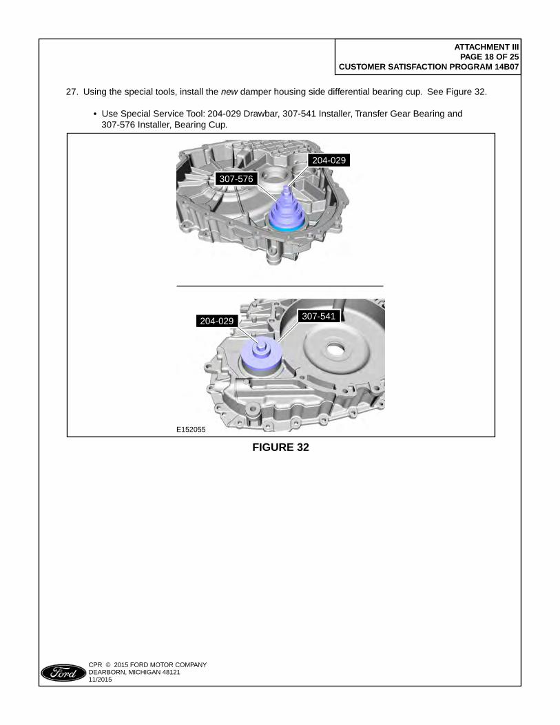
ATTACHMENT III PAGE 18 OF 25
CUSTOMER SATISFACTION PROGRAM 14B07
CPR © 2015 FORD MOTOR COMPANYDEARBORN, MICHIGAN 4812111/2015
E152055
204-029
307-576
307-541204-029
FIGURE 32
27. Using the special tools, install the new damper housing side differential bearing cup. See Figure 32.
• Use Special Service Tool: 204-029 Drawbar, 307-541 Installer, Transfer Gear Bearing and 307-576 Installer, Bearing Cup.
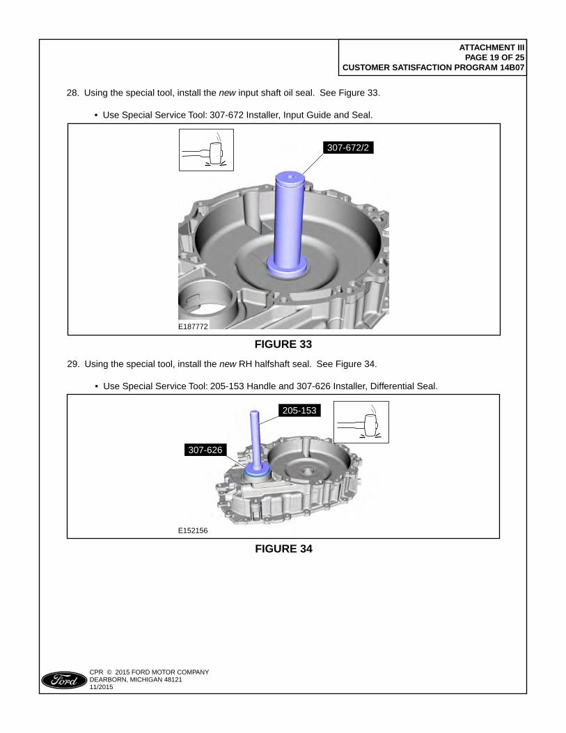
ATTACHMENT III PAGE 19 OF 25
CUSTOMER SATISFACTION PROGRAM 14B07
CPR © 2015 FORD MOTOR COMPANYDEARBORN, MICHIGAN 4812111/2015
307-672/2307-672/2
E187772
FIGURE 33
28. Using the special tool, install the new input shaft oil seal. See Figure 33.
• Use Special Service Tool: 307-672 Installer, Input Guide and Seal.
E152156
205-153
307-626
FIGURE 34
29. Using the special tool, install the new RH halfshaft seal. See Figure 34.
• Use Special Service Tool: 205-153 Handle and 307-626 Installer, Differential Seal.
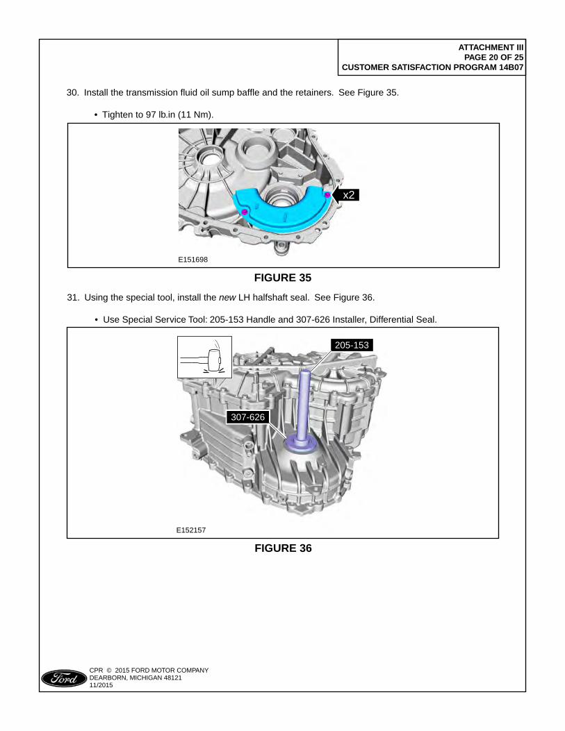
ATTACHMENT III PAGE 20 OF 25
CUSTOMER SATISFACTION PROGRAM 14B07
CPR © 2015 FORD MOTOR COMPANYDEARBORN, MICHIGAN 4812111/2015
E151698
x2
FIGURE 35
30. Install the transmission fluid oil sump baffle and the retainers. See Figure 35.
• Tighten to 97 lb.in (11 Nm).
E152157
205-153
307-626
FIGURE 36
31. Using the special tool, install the new LH halfshaft seal. See Figure 36.
• Use Special Service Tool: 205-153 Handle and 307-626 Installer, Differential Seal.
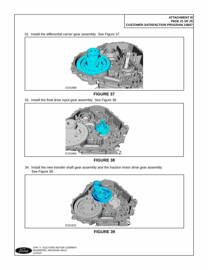
ATTACHMENT III PAGE 21 OF 25
CUSTOMER SATISFACTION PROGRAM 14B07
CPR © 2015 FORD MOTOR COMPANYDEARBORN, MICHIGAN 4812111/2015
E151686
FIGURE 37
32. Install the differential carrier gear assembly. See Figure 37.
E151663
FIGURE 38
33. Install the final drive input gear assembly. See Figure 38.
E151631
FIGURE 39
34. Install the new transfer shaft gear assembly and the traction motor drive gear assembly. See Figure 39.
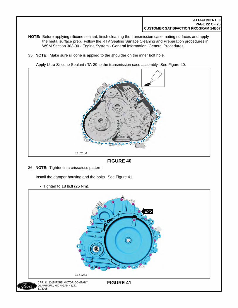
ATTACHMENT III PAGE 22 OF 25
CUSTOMER SATISFACTION PROGRAM 14B07
CPR © 2015 FORD MOTOR COMPANYDEARBORN, MICHIGAN 4812111/2015
E152154
FIGURE 40
NOTE: Before applying silicone sealant, finish cleaning the transmission case mating surfaces and apply the metal surface prep. Follow the RTV Sealing Surface Cleaning and Preparation procedures in WSM Section 303-00 - Engine System - General Information, General Procedures. 35. NOTE: Make sure silicone is applied to the shoulder on the inner bolt hole.
Apply Ultra Silicone Sealant / TA-29 to the transmission case assembly. See Figure 40.
E151264
FIGURE 41
36. NOTE: Tighten in a crisscross pattern.
Install the damper housing and the bolts. See Figure 41. • Tighten to 18 lb.ft (25 Nm).
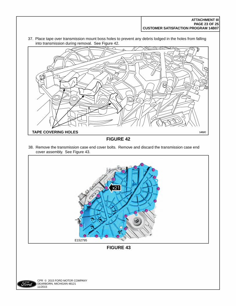
ATTACHMENT III PAGE 23 OF 25
CUSTOMER SATISFACTION PROGRAM 14B07
CPR © 2015 FORD MOTOR COMPANYDEARBORN, MICHIGAN 4812111/2015
1452C
PLACE COPY HERE
PLACE COPY HERE
PLACE COPY HERE
PASS INSPECTION
STUD FORMISSING NUT
STUD FORMISSING NUT
TAPE COVERING HOLES
FIGURE 42
37. Place tape over transmission mount boss holes to prevent any debris lodged in the holes from falling into transmission during removal. See Figure 42.
E152795
FIGURE 43
38. Remove the transmission case end cover bolts. Remove and discard the transmission case end cover assembly. See Figure 43.
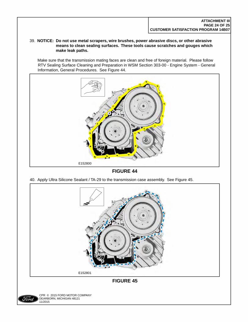
ATTACHMENT III PAGE 24 OF 25
CUSTOMER SATISFACTION PROGRAM 14B07
CPR © 2015 FORD MOTOR COMPANYDEARBORN, MICHIGAN 4812111/2015
39. NOTICE: Do not use metal scrapers, wire brushes, power abrasive discs, or other abrasive means to clean sealing surfaces. These tools cause scratches and gouges which make leak paths.
Make sure that the transmission mating faces are clean and free of foreign material. Please follow RTV Sealing Surface Cleaning and Preparation in WSM Section 303-00 - Engine System - General Information, General Procedures. See Figure 44.
E152800
FIGURE 44
40. Apply Ultra Silicone Sealant / TA-29 to the transmission case assembly. See Figure 45.
E152801
FIGURE 45
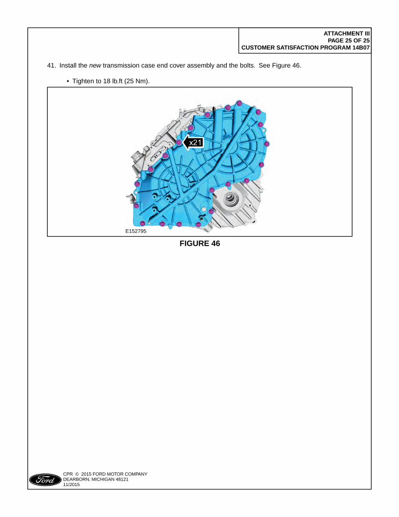
ATTACHMENT III PAGE 25 OF 25
CUSTOMER SATISFACTION PROGRAM 14B07
CPR © 2015 FORD MOTOR COMPANYDEARBORN, MICHIGAN 4812111/2015
E152795
FIGURE 46
41. Install the new transmission case end cover assembly and the bolts. See Figure 46.
• Tighten to 18 lb.ft (25 Nm).
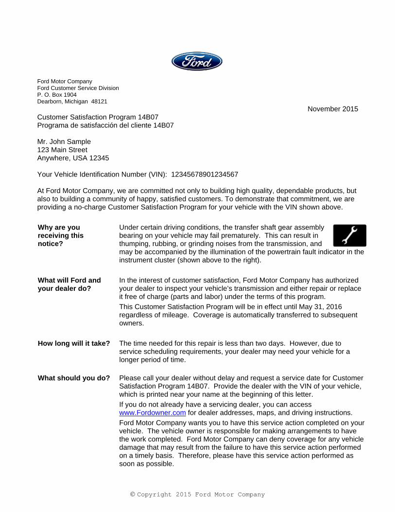
Copyright 2015 Ford Motor Company
Ford Motor Company Ford Customer Service Division P. O. Box 1904 Dearborn, Michigan 48121
November 2015 Customer Satisfaction Program 14B07 Programa de satisfacción del cliente 14B07 Mr. John Sample 123 Main Street Anywhere, USA 12345 Your Vehicle Identification Number (VIN): 12345678901234567 At Ford Motor Company, we are committed not only to building high quality, dependable products, but also to building a community of happy, satisfied customers. To demonstrate that commitment, we are providing a no-charge Customer Satisfaction Program for your vehicle with the VIN shown above.
Why are you receiving this notice?
Under certain driving conditions, the transfer shaft gear assembly bearing on your vehicle may fail prematurely. This can result in thumping, rubbing, or grinding noises from the transmission, and may be accompanied by the illumination of the powertrain fault indicator in the instrument cluster (shown above to the right).
What will Ford and your dealer do?
In the interest of customer satisfaction, Ford Motor Company has authorized your dealer to inspect your vehicle’s transmission and either repair or replace it free of charge (parts and labor) under the terms of this program.
This Customer Satisfaction Program will be in effect until May 31, 2016 regardless of mileage. Coverage is automatically transferred to subsequent owners.
How long will it take? The time needed for this repair is less than two days. However, due to service scheduling requirements, your dealer may need your vehicle for a longer period of time.
What should you do? Please call your dealer without delay and request a service date for Customer Satisfaction Program 14B07. Provide the dealer with the VIN of your vehicle, which is printed near your name at the beginning of this letter.
If you do not already have a servicing dealer, you can access www.Fordowner.com for dealer addresses, maps, and driving instructions.
Ford Motor Company wants you to have this service action completed on your vehicle. The vehicle owner is responsible for making arrangements to have the work completed. Ford Motor Company can deny coverage for any vehicle damage that may result from the failure to have this service action performed on a timely basis. Therefore, please have this service action performed as soon as possible.
Copyright 2015 Ford Motor Company
Have you previously paid for this repair?
If you have previously paid for a repair that addresses the issue described in this letter, you still need to have this service action performed to ensure the correct parts and procedures were used.
If the previously paid for repair was performed before the date of this letter, you may be eligible for a refund. Refunds will only be provided for service related to transmission repairs related to transfer shaft gear assembly bearing failure. To verify eligibility and expedite reimbursement, give your paid original receipt to your dealer before January 31, 2016. To avoid delays, do not send receipts to Ford Motor Company.
What if you no longer own this vehicle?
If you no longer own this vehicle, and have an address for the current owner, please forward this letter to the new owner.
You received this notice because our records, which are based primarily on state registration and title data, indicate that you are the current owner.
Can we assist you further?
If you have difficulties getting your vehicle repaired promptly and without charge, please contact your dealership's Service Manager for assistance.
RETAIL OWNERS: If you still have concerns, please contact the Ford Motor Company Customer Relationship Center at 1-866-436-7332 and one of our representatives will be happy to assist you. For the hearing impaired call 1-800-232-5952 (TDD). Representatives are available Monday through Friday: 8:00AM – 8:00PM (Eastern Time).
If you wish to contact us through the Internet, our address is: www.Fordowner.com.
Si necesita ayuda o tiene alguna pregunta, por favor llame al Centro de Relación con Clientes al 1-866-436-7332 y presione 2 para Español.
FLEET OWNERS: If you still have concerns, please contact the Fleet Customer Information Center at 1-800-34-FLEET, Option #3 and one of our representatives will be happy to assist you. Representatives are available Monday through Friday: 8:00AM - 8:00PM (Eastern Time).
Or you may contact us through the Internet at www.fleet.ford.com.
Thank you for your attention to this important matter.
Ford Customer Service Division
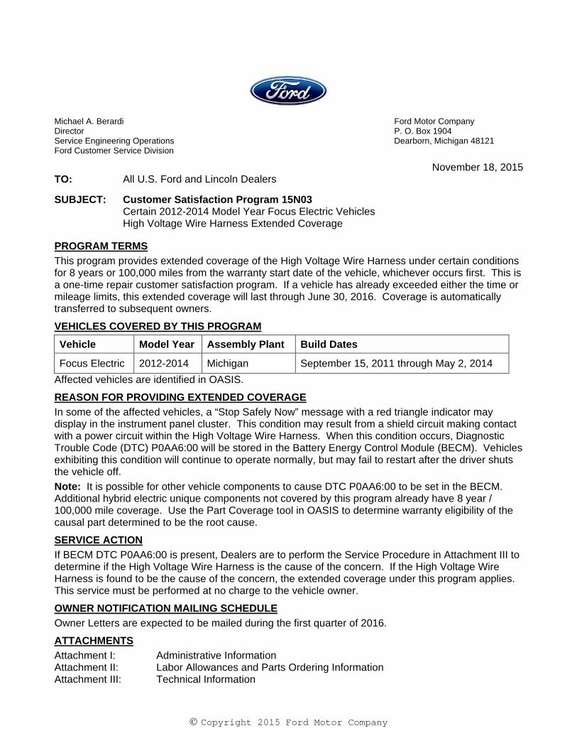
Copyright 2015 Ford Motor Company
Michael A. Berardi Ford Motor Company Director P. O. Box 1904 Service Engineering Operations Dearborn, Michigan 48121 Ford Customer Service Division
November 18, 2015 TO: All U.S. Ford and Lincoln Dealers
SUBJECT: Customer Satisfaction Program 15N03 Certain 2012-2014 Model Year Focus Electric Vehicles High Voltage Wire Harness Extended Coverage
PROGRAM TERMS
This program provides extended coverage of the High Voltage Wire Harness under certain conditions for 8 years or 100,000 miles from the warranty start date of the vehicle, whichever occurs first. This is a one-time repair customer satisfaction program. If a vehicle has already exceeded either the time or mileage limits, this extended coverage will last through June 30, 2016. Coverage is automatically transferred to subsequent owners.
VEHICLES COVERED BY THIS PROGRAM
Vehicle Model Year Assembly Plant Build Dates
Focus Electric 2012-2014 Michigan September 15, 2011 through May 2, 2014
Affected vehicles are identified in OASIS.
REASON FOR PROVIDING EXTENDED COVERAGE
In some of the affected vehicles, a “Stop Safely Now” message with a red triangle indicator may display in the instrument panel cluster. This condition may result from a shield circuit making contact with a power circuit within the High Voltage Wire Harness. When this condition occurs, Diagnostic Trouble Code (DTC) P0AA6:00 will be stored in the Battery Energy Control Module (BECM). Vehicles exhibiting this condition will continue to operate normally, but may fail to restart after the driver shuts the vehicle off.
Note: It is possible for other vehicle components to cause DTC P0AA6:00 to be set in the BECM. Additional hybrid electric unique components not covered by this program already have 8 year / 100,000 mile coverage. Use the Part Coverage tool in OASIS to determine warranty eligibility of the causal part determined to be the root cause.
SERVICE ACTION
If BECM DTC P0AA6:00 is present, Dealers are to perform the Service Procedure in Attachment III to determine if the High Voltage Wire Harness is the cause of the concern. If the High Voltage Wire Harness is found to be the cause of the concern, the extended coverage under this program applies. This service must be performed at no charge to the vehicle owner.
OWNER NOTIFICATION MAILING SCHEDULE
Owner Letters are expected to be mailed during the first quarter of 2016.
ATTACHMENTS
Attachment I: Administrative Information Attachment II: Labor Allowances and Parts Ordering Information Attachment III: Technical Information
Copyright 2015 Ford Motor Company
QUESTIONS & ASSISTANCE
For questions and assistance, contact the Special Service Support Center (SSSC) via the SSSC Web Contact Site. The SSSC Web Contact Site can be accessed through the Professional Technician Society (PTS) website using the SSSC link listed at the bottom of the OASIS VIN report screen or listed under the SSSC tab.
Sincerely,
Michael A. Berardi
Copyright 2015 Ford Motor Company
ATTACHMENT I Page 1 of 2
Customer Satisfaction Program 15N03 Certain 2012-2014 Model Year Focus Electric Vehicles
High Voltage Wire Harness Extended Coverage
OASIS ACTIVATION
OASIS will be activated on November 18, 2015.
FSA VIN LISTS ACTIVATION
FSA VIN Lists will not be activated for this service action.
STOCK VEHICLES
Do not perform this program unless the affected vehicle exhibits the covered condition.
SOLD VEHICLES
Only owners with affected vehicles that exhibit the covered condition will be directed to dealers for repairs.
TITLE BRANDED / SALVAGED VEHICLES
Vehicles with cancelled warranties are not eligible for this service action.
ADDITIONAL LABOR TIME AND/OR PARTS
Submit a request to the SSSC Web Contact Site prior to the repair if you have any of the following:
Damage that you believe was caused by the covered condition.
A condition that requires additional labor and/or parts to complete the repair.
Aftermarket equipment or non-Ford modifications to the vehicle which might prevent the repair of the covered condition.
Requests for approval after completion of the repair may not be granted. Additional related damage parts are subject to random selection for return to the Ford Warranty Parts Analysis Center (WPAC).

Copyright 2015 Ford Motor Company
ATTACHMENT I Page 2 of 2
Customer Satisfaction Program 15N03 Certain 2012-2014 Model Year Focus Electric Vehicles
High Voltage Wire Harness Extended Coverage
OWNER REFUNDS
Ford Motor Company is offering a refund for owner-paid repairs covered by this program if the repair was performed before the date of the Owner Notification Letter. This refund offer expires June 30, 2016.
Dealers are also pre-approved to refund owner-paid emergency repairs that were performed away from an authorized servicing dealer after the date of the Owner Notification Letter. There is no expiration date for emergency repair refunds. Non-covered repairs, or those judged by Ford to be excessive, will not be reimbursed.
Refunds will only be provided for the cost associated with performing diagnostics and replacement of the High Voltage Wire Harness when BECM DTC P0AA6:00 was present and the root cause component was determined to be the High Voltage Wire Harness.
RENTAL VEHICLES
If a customer's vehicle requires the replacement of the High Voltage Wire Harness under this program, Ford Motor Company will pay for up to 2 days of vehicle rental. Follow Extended Service Plan (ESP) guidelines for dollar amounts. The daily rate can include applicable taxes but must not exceed the stated daily rate. Rentals will only be reimbursed for the day(s) the vehicle is at the dealership for part replacement. Prior approval for more than 2 rental days is required from the SSSC via the SSSC Web Contact Site. To guarantee the shortest delivery time, an emergency order for parts must be placed.
CLAIMS PREPARATION AND SUBMISSION
This is a one-time repair program and also applies to vehicles that are within the New Vehicle Limited Warranty coverage period. When a vehicle is determined to exhibit this concern, repairs should be claimed against Program Code 15N03.
Enter claims using Direct Warranty Entry (DWE) or One Warranty Solution (OWS).
o DWE: refer to ACESII manual for claims preparation and submission information.
o OWS: when entering claims in DMS software, select claim type 31: Field Service Action. The FSA number (15N03) is the sub code.
Additional labor and/or parts must be claimed as related damage on a separate repair line from which the FSA is claimed. Additional labor and /or parts require prior approval from the SSSC via the SSSC Web Contact Site.
Submit refunds on a separate repair line.
- Program Code: 15N03 - Misc. Expense: ADMIN
- Misc. Expense: REFUND - Misc. Expense: 0.2 Hrs.
Multiple refunds should be submitted on one repair line and the invoice details for each repair should be detailed in the comments section of the claim.
For rental vehicle claiming, follow Extended Service Plan (ESP) guidelines for dollar amounts. Enter the total amount of the rental expense under Miscellaneous Expense code "Rental".
Copyright 2015 Ford Motor Company
ATTACHMENT II Page 1 of 1
Customer Satisfaction Program 15N03 Certain 2012-2014 Model Year Focus Electric Vehicles
High Voltage Wire Harness Extended Coverage
LABOR ALLOWANCES
Description Labor Operation Labor Time
Perform Service Procedure Diagnostics and Replace the High Voltage Wire Harness
15N03B 4.0 Hours
PARTS REQUIREMENTS / ORDERING INFORMATION
Part Number Description Order Quantity
CM5Z-14A318-D High Voltage Wire Harness 1
CV6Z-00812-A Bolt – Cross Member Reinforcement Bracket 1
Note: To guarantee the shortest delivery time, an emergency order for parts must be placed.
The DOR/COR number for this program is 51011.
Order your parts requirements through normal order processing channels.
For questions regarding parts, contact SSSC via the SSSC Web Contact Site.
DEALER PRICE
For latest prices, refer to DOES II.
PARTS RETENTION AND RETURN
Follow the provisions of the Warranty and Policy Manual, Section 1 “WARRANTY PARTS RETENTION AND RETURN POLICIES.”
EXCESS STOCK RETURN
Excess stock returned for credit must have been purchased from Ford Customer Service Division in accordance with Policy Procedure Bulletin 4000.
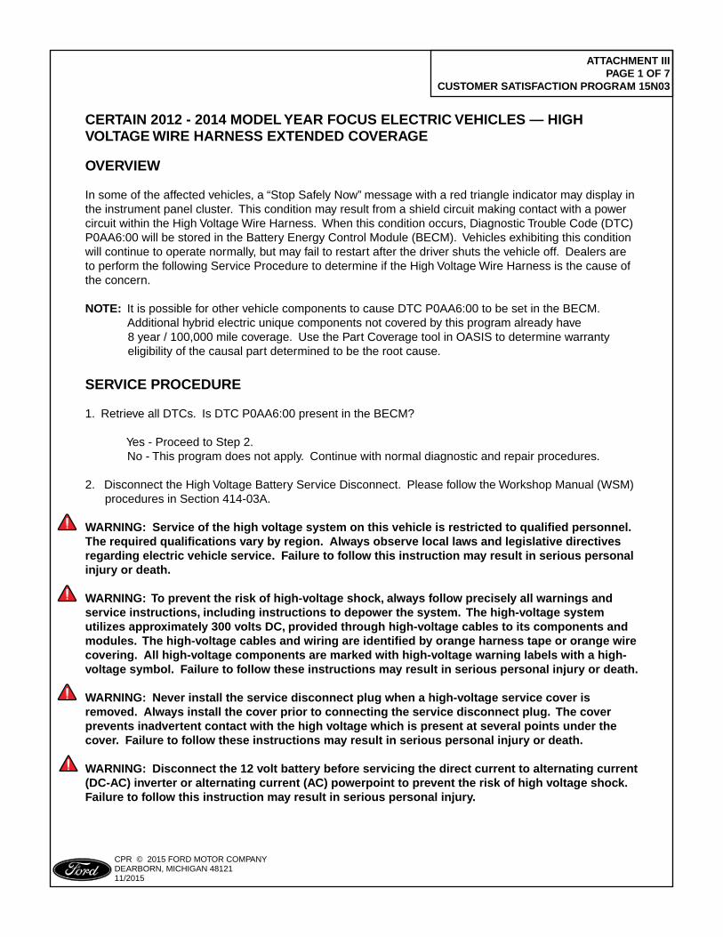
ATTACHMENT III PAGE 1 OF 7
CUSTOMER SATISFACTION PROGRAM 15N03
CPR © 2015 FORD MOTOR COMPANYDEARBORN, MICHIGAN 4812111/2015
CERTAIN 2012 - 2014 MOdEl YEAR FOCUS ElECTRIC VEHIClES — HIGH VOlTAGE wIRE HARNESS ExTENdEd COVERAGE
OVERVIEw
In some of the affected vehicles, a “Stop Safely Now” message with a red triangle indicator may display in the instrument panel cluster. This condition may result from a shield circuit making contact with a power circuit within the High Voltage Wire Harness. When this condition occurs, Diagnostic Trouble Code (DTC) P0AA6:00 will be stored in the Battery Energy Control Module (BECM). Vehicles exhibiting this condition will continue to operate normally, but may fail to restart after the driver shuts the vehicle off. Dealers are to perform the following Service Procedure to determine if the High Voltage Wire Harness is the cause of the concern.
NOTE: It is possible for other vehicle components to cause DTC P0AA6:00 to be set in the BECM. Additional hybrid electric unique components not covered by this program already have 8 year / 100,000 mile coverage. Use the Part Coverage tool in OASIS to determine warranty eligibility of the causal part determined to be the root cause.
SERVICE PROCEdURE
1. Retrieve all DTCs. Is DTC P0AA6:00 present in the BECM?
Yes - Proceed to Step 2. No - This program does not apply. Continue with normal diagnostic and repair procedures. 2. Disconnect the High Voltage Battery Service Disconnect. Please follow the Workshop Manual (WSM) procedures in Section 414-03A.
wARNING: Service of the high voltage system on this vehicle is restricted to qualified personnel. The required qualifications vary by region. Always observe local laws and legislative directives regarding electric vehicle service. Failure to follow this instruction may result in serious personal injury or death.
wARNING: To prevent the risk of high-voltage shock, always follow precisely all warnings and service instructions, including instructions to depower the system. The high-voltage system utilizes approximately 300 volts dC, provided through high-voltage cables to its components and modules. The high-voltage cables and wiring are identified by orange harness tape or orange wire covering. All high-voltage components are marked with high-voltage warning labels with a high-voltage symbol. Failure to follow these instructions may result in serious personal injury or death.
wARNING: Never install the service disconnect plug when a high-voltage service cover is removed. Always install the cover prior to connecting the service disconnect plug. The cover prevents inadvertent contact with the high voltage which is present at several points under the cover. Failure to follow these instructions may result in serious personal injury or death.
wARNING: disconnect the 12 volt battery before servicing the direct current to alternating current (dC-AC) inverter or alternating current (AC) powerpoint to prevent the risk of high voltage shock. Failure to follow this instruction may result in serious personal injury.
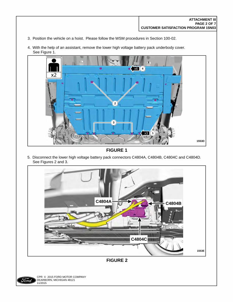
ATTACHMENT III PAGE 2 OF 7
CUSTOMER SATISFACTION PROGRAM 15N03
CPR © 2015 FORD MOTOR COMPANYDEARBORN, MICHIGAN 4812111/2015
FIGURE 1
1553D
PLACE COPY HERE
PLACE COPY HERE
PLACE COPY HERE
STUD FORMISSING NUT
STUD FORMISSING NUT
STUD FORMISSING NUT
x6
x3 1
2
3
4
x2
3. Position the vehicle on a hoist. Please follow the WSM procedures in Section 100-02.
4. With the help of an assistant, remove the lower high voltage battery pack underbody cover. See Figure 1.
5. Disconnect the lower high voltage battery pack connectors C4804A, C4804B, C4804C and C4804D. See Figures 2 and 3.
FIGURE 2
1553E
PLACE COPY HERE
PLACE COPY HERE
PLACE COPY HERE
STUD FORMISSING NUT
STUD FORMISSING NUT
STUD FORMISSING NUT
C4804C
C4804A C4804B
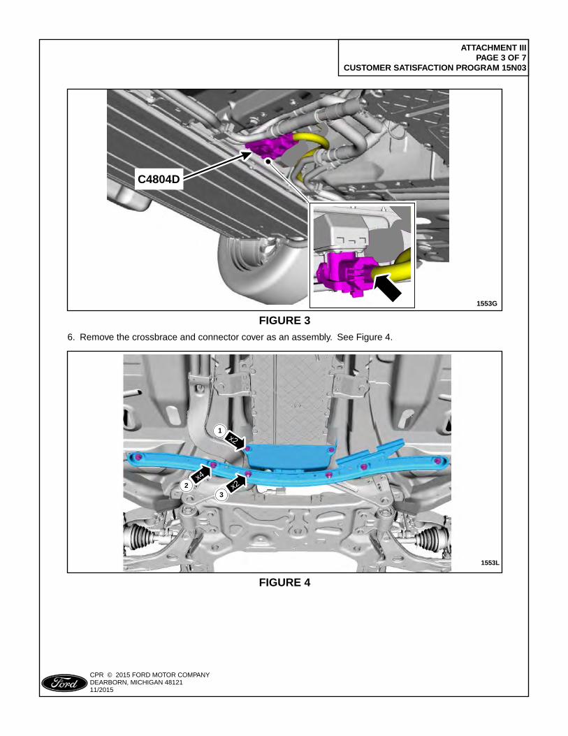
ATTACHMENT III PAGE 3 OF 7
CUSTOMER SATISFACTION PROGRAM 15N03
CPR © 2015 FORD MOTOR COMPANYDEARBORN, MICHIGAN 4812111/2015
FIGURE 3
1553G
PLACE COPY HERE
PLACE COPY HERE
PLACE COPY HERE
STUD FORMISSING NUT
STUD FORMISSING NUT
STUD FORMISSING NUT
C4804D
6. Remove the crossbrace and connector cover as an assembly. See Figure 4.
FIGURE 4
1553L
PLACE COPY HERE
PLACE COPY HERE
PLACE COPY HERE
STUD FORMISSING NUT
STUD FORMISSING NUT
STUD FORMISSING NUT
x2
x4
x2
x2 1
x4
x223
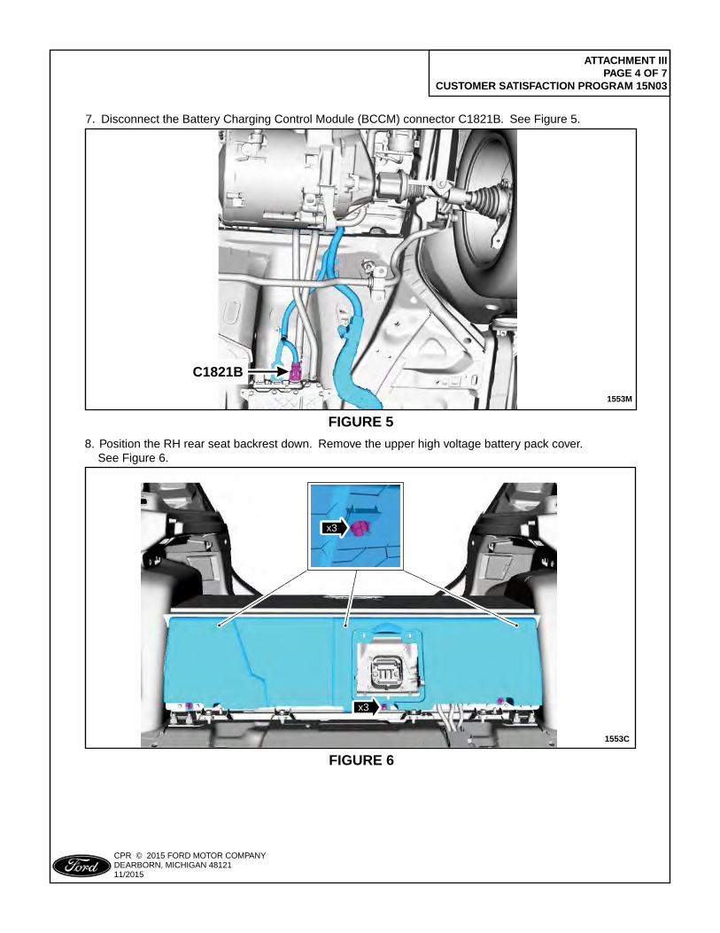
ATTACHMENT III PAGE 4 OF 7
CUSTOMER SATISFACTION PROGRAM 15N03
CPR © 2015 FORD MOTOR COMPANYDEARBORN, MICHIGAN 4812111/2015
7. Disconnect the Battery Charging Control Module (BCCM) connector C1821B. See Figure 5.
FIGURE 5
1553M
PLACE COPY HERE
PLACE COPY HERE
PLACE COPY HERE
STUD FORMISSING NUT
STUD FORMISSING NUT
STUD FORMISSING NUT
C1821B
FIGURE 6
1553C
PLACE COPY HERE
PLACE COPY HERE
PLACE COPY HERE
STUD FORMISSING NUT
STUD FORMISSING NUT
STUD FORMISSING NUT
x3x3
x3
8. Position the RH rear seat backrest down. Remove the upper high voltage battery pack cover. See Figure 6.
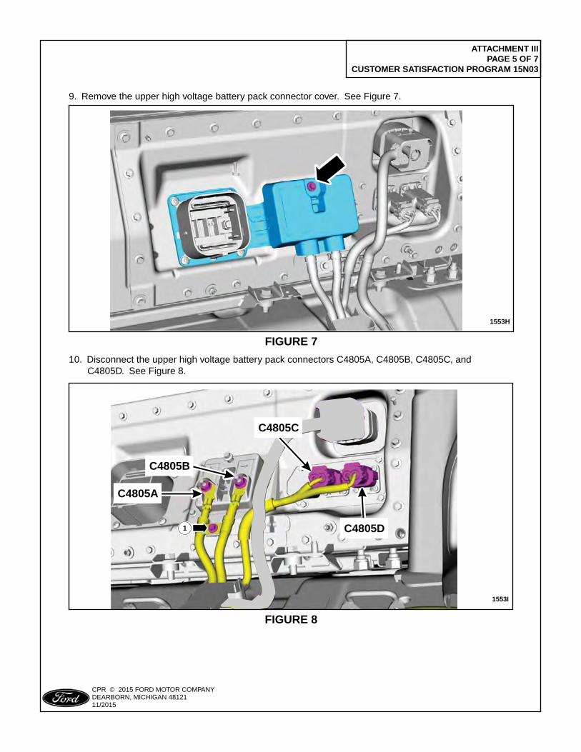
ATTACHMENT III PAGE 5 OF 7
CUSTOMER SATISFACTION PROGRAM 15N03
CPR © 2015 FORD MOTOR COMPANYDEARBORN, MICHIGAN 4812111/2015
FIGURE 7
1553H
PLACE COPY HERE
PLACE COPY HERE
PLACE COPY HERE
STUD FORMISSING NUT
STUD FORMISSING NUT
STUD FORMISSING NUT
9. Remove the upper high voltage battery pack connector cover. See Figure 7.
FIGURE 8
1553I
PLACE COPY HERE
PLACE COPY HERE
PLACE COPY HERE
STUD FORMISSING NUT
STUD FORMISSING NUT
STUD FORMISSING NUT
1
C4805C
C4805B
C4805D
C4805A
10. Disconnect the upper high voltage battery pack connectors C4805A, C4805B, C4805C, and C4805D. See Figure 8.
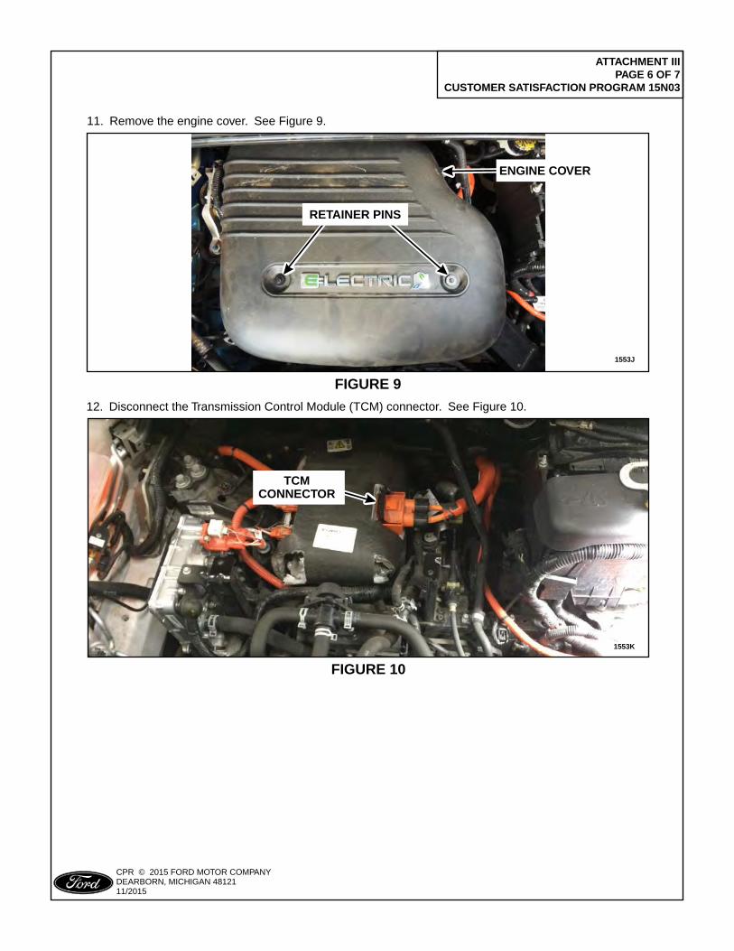
ATTACHMENT III PAGE 6 OF 7
CUSTOMER SATISFACTION PROGRAM 15N03
CPR © 2015 FORD MOTOR COMPANYDEARBORN, MICHIGAN 4812111/2015
11. Remove the engine cover. See Figure 9.
FIGURE 9
1553J
PLACE COPY HERE
PLACE COPY HERE
STUD FORMISSING NUT
STUD FORMISSING NUT
STUD FORMISSING NUT
RETAINER PINS
ENGINE COVER
12. Disconnect the Transmission Control Module (TCM) connector. See Figure 10.
FIGURE 10
1553K
TCMCONNECTOR
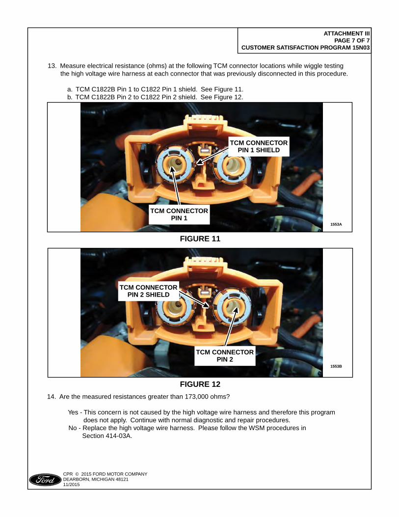
ATTACHMENT III PAGE 7 OF 7
CUSTOMER SATISFACTION PROGRAM 15N03
CPR © 2015 FORD MOTOR COMPANYDEARBORN, MICHIGAN 4812111/2015
13. Measure electrical resistance (ohms) at the following TCM connector locations while wiggle testing the high voltage wire harness at each connector that was previously disconnected in this procedure.
a. TCM C1822B Pin 1 to C1822 Pin 1 shield. See Figure 11. b. TCM C1822B Pin 2 to C1822 Pin 2 shield. See Figure 12.
FIGURE 11
1553A
PLACE COPY HERE
PLACE COPY HERE
PLACE COPY HERE
STUD FORMISSING NUT
STUD FORMISSING NUT
STUD FORMISSING NUT
TCM CONNECTORPIN 1
TCM CONNECTORPIN 1 SHIELD
FIGURE 12
14. Are the measured resistances greater than 173,000 ohms?
Yes - This concern is not caused by the high voltage wire harness and therefore this program does not apply. Continue with normal diagnostic and repair procedures. No - Replace the high voltage wire harness. Please follow the WSM procedures in Section 414-03A.
1553B
PLACE COPY HERE
PLACE COPY HERE
PLACE COPY HERE
STUD FORMISSING NUT
STUD FORMISSING NUT
STUD FORMISSING NUT
TCM CONNECTORPIN 2
TCM CONNECTORPIN 2 SHIELD
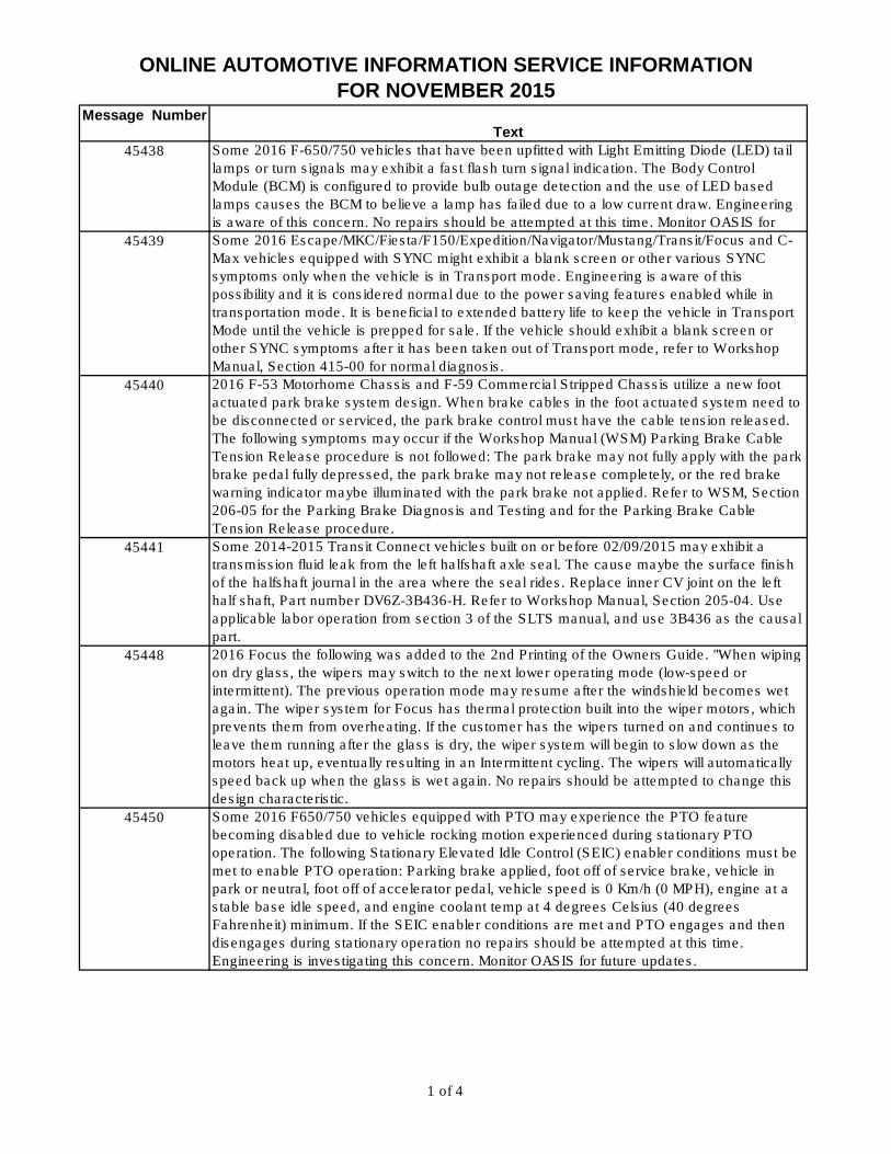
ONLINE AUTOMOTIVE INFORMATION SERVICE INFORMATION FOR NOVEMBER 2015
Message NumberText
45438 Some 2016 F-650/750 vehicles that have been upfitted with Light Emitting Diode (LED) tail
lamps or turn signals may exhibit a fast flash turn signal indication. The Body Control
Module (BCM) is configured to provide bulb outage detection and the use of LED based
lamps causes the BCM to believe a lamp has failed due to a low current draw. Engineering
is aware of this concern. No repairs should be attempted at this time. Monitor OASIS for
45439 Some 2016 Escape/MKC/Fiesta/F150/Expedition/Navigator/Mustang/Transit/Focus and C-
Max vehicles equipped with SYNC might exhibit a blank screen or other various SYNC
symptoms only when the vehicle is in Transport mode. Engineering is aware of this
possibility and it is considered normal due to the power saving features enabled while in
transportation mode. It is beneficial to extended battery life to keep the vehicle in Transport
Mode until the vehicle is prepped for sale. If the vehicle should exhibit a blank screen or
other SYNC symptoms after it has been taken out of Transport mode, refer to Workshop
Manual, Section 415-00 for normal diagnosis.
45440 2016 F-53 Motorhome Chassis and F-59 Commercial Stripped Chassis utilize a new foot
actuated park brake system design. When brake cables in the foot actuated system need to
be disconnected or serviced, the park brake control must have the cable tension released.
The following symptoms may occur if the Workshop Manual (WSM) Parking Brake Cable
Tension Release procedure is not followed: The park brake may not fully apply with the park
brake pedal fully depressed, the park brake may not release completely, or the red brake
warning indicator maybe illuminated with the park brake not applied. Refer to WSM, Section
206-05 for the Parking Brake Diagnosis and Testing and for the Parking Brake Cable
Tension Release procedure.
45441 Some 2014-2015 Transit Connect vehicles built on or before 02/09/2015 may exhibit a
transmission fluid leak from the left halfshaft axle seal. The cause maybe the surface finish
of the halfshaft journal in the area where the seal rides. Replace inner CV joint on the left
half shaft, Part number DV6Z-3B436-H. Refer to Workshop Manual, Section 205-04. Use
applicable labor operation from section 3 of the SLTS manual, and use 3B436 as the causal
part.
45448 2016 Focus the following was added to the 2nd Printing of the Owners Guide. "When wiping
on dry glass, the wipers may switch to the next lower operating mode (low-speed or
intermittent). The previous operation mode may resume after the windshield becomes wet
again. The wiper system for Focus has thermal protection built into the wiper motors, which
prevents them from overheating. If the customer has the wipers turned on and continues to
leave them running after the glass is dry, the wiper system will begin to slow down as the
motors heat up, eventually resulting in an Intermittent cycling. The wipers will automatically
speed back up when the glass is wet again. No repairs should be attempted to change this
design characteristic.
45450 Some 2016 F650/750 vehicles equipped with PTO may experience the PTO feature
becoming disabled due to vehicle rocking motion experienced during stationary PTO
operation. The following Stationary Elevated Idle Control (SEIC) enabler conditions must be
met to enable PTO operation: Parking brake applied, foot off of service brake, vehicle in
park or neutral, foot off of accelerator pedal, vehicle speed is 0 Km/h (0 MPH), engine at a
stable base idle speed, and engine coolant temp at 4 degrees Celsius (40 degrees
Fahrenheit) minimum. If the SEIC enabler conditions are met and PTO engages and then
disengages during stationary operation no repairs should be attempted at this time.
Engineering is investigating this concern. Monitor OASIS for future updates.
1 of 4
ONLINE AUTOMOTIVE INFORMATION SERVICE INFORMATION FOR NOVEMBER 2015
45451 Some 2016 E-Series E450 Cutaways and Stripped Chassis stretched vehicles equipped
with a 6.8L engine and 6R140 transmission may exhibit a vibration and moan at 55 MPH to
65 MPH under load. Engineering is currently investigating this condition and is developing a
service repair procedure to be available shortly. Do not attempt repair or replacement of
components at this time. Monitor QVM and OASIS bulletins for updates.
45452 Some 2015 F-150 XL and or XLT vehicles equipped with an ESOF transfer case, built on or
before 6/16/2015, may exhibit a rotational noise from the transfer case while in 2-wheel high
(2H) that does not change significantly when shifted to 4-wheel high (4H). The noise can be
described as ticking, scraping or rubbing noise that occurs between 32 Km/h (20 MPH) to
80 Km/h (50 MPH). The noise is most noticeable at lower speeds and will increase
frequency with speed. To eliminate this concern, replace the Front Planet Carrier (7A398)
and Ring Rear (7A153). Refer to WSM, Section 308-07. Use applicable labor operations
from Section 7 of the SLTS manual.
45455 Some 2013-2016 MKZs may exhibit a chuckle or knocking noise on one or both sides in the
rear of the vehicle while traveling over bumps. To correct the concern, replace both rear
upper shock mounts (HG9Z-18A161-A). Refer to the Rear Shock Absorber removal and
installation procedure in the Workshop Manual (WSM), Section 204-02. While removing the
shocks, inpsect for fluid leakage and replace the rear shock absorber(s) if abnormal fluid
leakage beyond normal seepage is present (visible drip/run). Use the applicable 18125AT
labor operation from section 5 of the SLTS manual.
45456 Some 2010-2012 Fusion and 2010-2011 Milan vehicles equipped with manual temperature
control may experience the climate control system intermittently blowing warm air when cold
air is selected or the a/c is turned on. This may be due to the blend door defaulting to a
position of 65-70% that mixes warm air and cold air. To correct the concern, reprogram the
HVAC module using IDS version 98.01 or higher. Make sure you are connected to the
internet when entering module programming to obtain the latest updates. Use applicable
12651D labor operations in section 10 of the SLTS manual and causal part 19980 for
reflash only. 2010-2011 Fusion/Milan would only be affected if the HVAC module has been
replaced in service history. The scan tool will then identify the HVAC as having a later
45457 Some 2016 Focus vehicles built on or before 9/23/15, may exhibit an incorrect average fuel
economy reading. Focus clusters have two trip computers (trip 1 and trip 2). If the customer
is using one for short trips (reset at every refill) and the other for long trips (no reset since
he/she owns the vehicle) the issue may be present after either trip computer reads greater
than 2000 miles. Reprogram the instrument panel cluster (IPC) to resolve the concern,
using IDS version 98.01 or higher. Make sure you are connected to the internet when
entering module programming to obtain the latest updates. Calibration files may also be
obtained at www.motorcraftservice.com. Use applicable 12651D labor operations in section
10 of the SLTS manual, use causal part 10849 for reprogram only.
45458 Some 2016 MKX vehicles equipped with a Harman Revel or Harman Revel Ultima audio
system built on or before 11/3/2015, may exhibit a 12-volt battery that is unable to maintain
a charge or becomes discharged. To correct the concern, reprogram the Audio Digital
Signal Processing (DSP) module to the latest calibration using IDS version 98.01 and
higher. Make sure you are connected to the internet when entering module programming to
obtain the latest calibration. Calibration files may also be obtained at
www.motorcraftservice.com. For warranty claiming, use causal part 18B849 and applicable
12651D labor operations in the Service Labor Time Standards Manual, Section 10.
2 of 4
ONLINE AUTOMOTIVE INFORMATION SERVICE INFORMATION FOR NOVEMBER 2015
45459 Some 2015-2016 Transit vehicles may exhibit front seat safety belts that do not extend or
retract properly or may exhibit an abnormal noise. Verify if the vehicle has been modified, in
particular if a bulkhead partition between the front seats and cargo area has been added to
the vehicle. Fasteners or holes in the lower b-pillar are indicators that the seat belt retractor
mechanism could have been compromised. If diagnostics lead to retractor replacement,
inspect for drill or screw holes in the retractor housing. Damage to the seat belt retractor
caused by a vehicle modifier is not warrantable.
45461 Some 2015 and 2016 Transit High Roof Wagons built on or after 6/2/2015 may have been
shipped with a headliner panel that was not properly seated, causing a gap at the C and/or
C 1/2 pillar(s). In most cases the condition can be resolved by removing the associated pillar
trim panel, carefully seating the headliner pillar tab to the pillar block, and while holding the
headliner in place, reinstalling the pillar trim panel. Headliner pillar tab damage can be
repaired with service kit EK4Z-6151916-A. Note: Headliner retention in these areas is
intentionally delicate to allow for proper air curtain deployment. Visual inspection is adequate
for this condition, while physical tugging or prying may damage an otherwise acceptable
connection.
45462 Some 2015-2016 F-Super Duty pickups equipped with a 6.7L diesel engines may exhibit a
runs rough condition during exhaust regeneration. This condition may occur when the
vehicle is idled for prolonged periods of time or when frequently driven short distances that
�don t allow the regeneration cycle to complete. A calibration to address this concern is
expected to be available in late March 2016. It is allowable to perform TSB 15-0124 until the
calibration becomes available. To avoid a repeat occurrence customers need to be
reminded to follow the drive cycle recommendations in the Customer Information Sheet
45463 2013-2016 MKX/Escape/MKC/Fusion/MKZ/Flex/MKT and 2013-2015 Edge all wheel drive
(AWD) vehicles may now be serviced with a new rear drive unit (RDU) service kit. For
vehicles with symptoms including shudder, chatter, grinding, banging, popping, clicking or
binding from the RDU at any time, or inadequate torque at the rear wheels, service the RDU
using service kit CV6Z-4A232-A. Workshop Manual (WSM) diagnostics are in the process
of being updated. A repair procedure for the ATC clutch is published. Refer to WSM,
Section 205-02. Use applicable 7453D labor operation(s) in the Service Labor Time
Standards (SLTS) manual, Section 7.
45474 Some 2013-2014 Fusion, MKZ, and Escape vehicles built on or before 1/31/2014 and
equipped with a 6F35 may exhibit a harsh forward engagement. If no DTCs are present and
the fluid level is correct, this may be due to a worn forward clutch piston seal. The surface
finish on the bore of the center support could cause the forward clutch piston to wear
prematurely. To correct the concern, perform a transmission overhaul and install a new
center support. Refer to section 7 of the SLTS manual for appropriate labor times.
45480 Some 2011-2016 F-Super Duty vehicles equipped with Snow Prep Package option (Order
Guide option 473) may exhibit an erratic operation of the radio, climate Control and
Instrument Panel Cluster(IPC) during High Use Of Snow Plow. This is due to excessive
electrical voltage spikes caused when the snow plow motor stalls. To avoid snow plow
motor stall the operator should avoid continued pressing of the snow plow adjustment
switch. These vehicles are equipped with a New Body Control Module (BCM) and its
function is to provide protection against excessive voltage spikes, by shutting down circuit(s)
operation. The BCM strategy may interpret the excessive voltage or snowplow operation, as
an over voltage condition, causing the BCM to load shed (short term momentarily turn off)
the interior lamps/components. These conditions are considered normal vehicle function an
no repairs should be attempted.
3 of 4
ONLINE AUTOMOTIVE INFORMATION SERVICE INFORMATION FOR NOVEMBER 2015
45481 Some 2016 F-650/F-750 and/or 2013-2016 F-Super Duty vehicles equipped with One Touch
auto up / down power windows may exhibit erratic operation with possibility of a different
window(s) being inoperative after each key cycle. Check for possible aftermarket equipment
added to the accessory delay circuits of the body control module (BCM). Splicing into the
accessory delay circuits can cause voltage to drop, when the ignition key is turned on
resulting in power window motor(s) to be inoperative for a key cycle. Refer to Warranty and
policy manual for Aftermarket accessories policies. If no aftermarket accessories are
present and/or a functional operation is suspect, refer to Workshop Manual (WSM), Section
501-11 for diagnostics and repairs. Follow Warranty Policy Manual for vehicle coverage.
45482 After installing a replacement HVAC module on a 2010-2012 Fusion or 2010-2011 Milan
with manual temperature control, verify that the replacement module is at the latest
calibration using IDS version 98.01 or higher. Make sure you are connected to the internet
when entering module programming to obtain the latest updates. Calibration files may also
be obtained at www.motorcraftservice.com. Use applicable 12651D labor operations in
section 10 of the SLTS manual.
45485 Some 2015-2016 Focus vehicles built on or before 9/23/2015 may exhibit an incorrect
average fuel economy reading. Focus clusters have two trip computers (trip 1 and trip 2). If
the customer is using one for short trips (reset at every refill) and the other for long trips (no
reset since he/she owns the vehicle) the issue may be present after either trip computer
reads greater than 3219 Km (2000 miles). Reprogram the instrument panel cluster (IPC) to
resolve the concern, using IDS version 98.01 or higher. Make sure you are connected to the
internet when entering module programming to obtain the latest updates. Calibration files
may also be obtained at www.motorcraftservice.com. Use applicable 12651D labor
operations in section 10 of the SLTS manual, use causal part 10849 for reprogram.
4 of 4