
Lightweight Module Construction - Calgary Model Railway Constr_160114.pdf · Lightweight Module...
30
Lightweight Module Construction Clinic for Calgary Model Trainmen Ironside 13 Jan 2016
Transcript of Lightweight Module Construction - Calgary Model Railway Constr_160114.pdf · Lightweight Module...

Lightweight Module Construction
Clinic for Calgary Model Trainmen
Ironside 13 Jan 2016

Learn by Doing Then do it again
(or learn by someone else doing)

Full Config 21’ (earlier in life) full Timesaver
Small Config 15’ (later in life) S7 (2’) sub for S3/S4 Timesaver (8’)
S1
S5
S7
S6
S2
S1
S5 S4
S6
S2 S3
Ogden Road

J Ironside and Son
Equipment Sales (Section 7)
S7 Old
Can be used in place of Ogden Industrial
(Timesaver) S3/S4 for smaller footprint
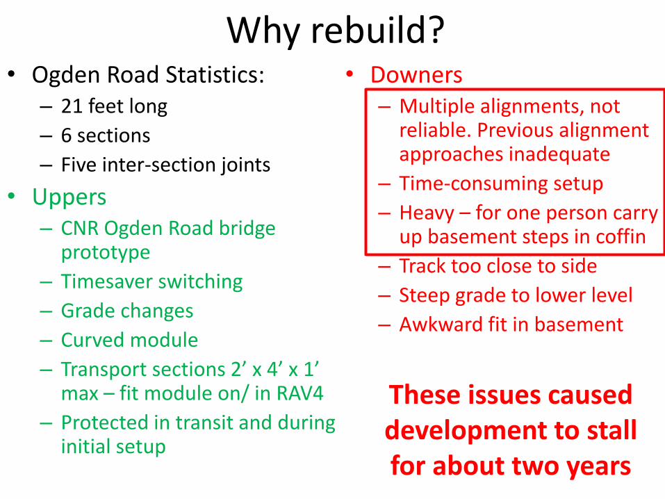
Why rebuild? • Ogden Road Statistics:
– 21 feet long
– 6 sections
– Five inter-section joints
• Uppers – CNR Ogden Road bridge
prototype
– Timesaver switching
– Grade changes
– Curved module
– Transport sections 2’ x 4’ x 1’ max – fit module on/ in RAV4
– Protected in transit and during initial setup
• Downers – Multiple alignments, not
reliable. Previous alignment approaches inadequate
– Time-consuming setup
– Heavy – for one person carry up basement steps in coffin
– Track too close to side
– Steep grade to lower level
– Awkward fit in basement
These issues caused development to stall for about two years

Rebuild
Old
New

Overview Objective
Lightweight, portable
Easy section setup
– no tools except socket
driver for coffin removal
(Free-mo ends standard
clamps/ fitter rails)
Protection in transit
and setup
Approaches
• Light Materials – thinner ply, foam top
with plywood beam sub-roadbed
• Strength through structure
• Flexible vs stiff
• Handholds including in coffins
• Butt joint tracks
• Dowel alignment
• Sprung cam latch connection
• Knob-clamped legs
• Electrical pigtail one end only
• Legs installed prior to coffin removal
• End plates protect track butt joints and
scenery
• Coffin protects scenery
Improved
Improved
Preserved

Harvested old stuff
Before harvest
Only electrical
infrastructure installed
S1 Old S3 New
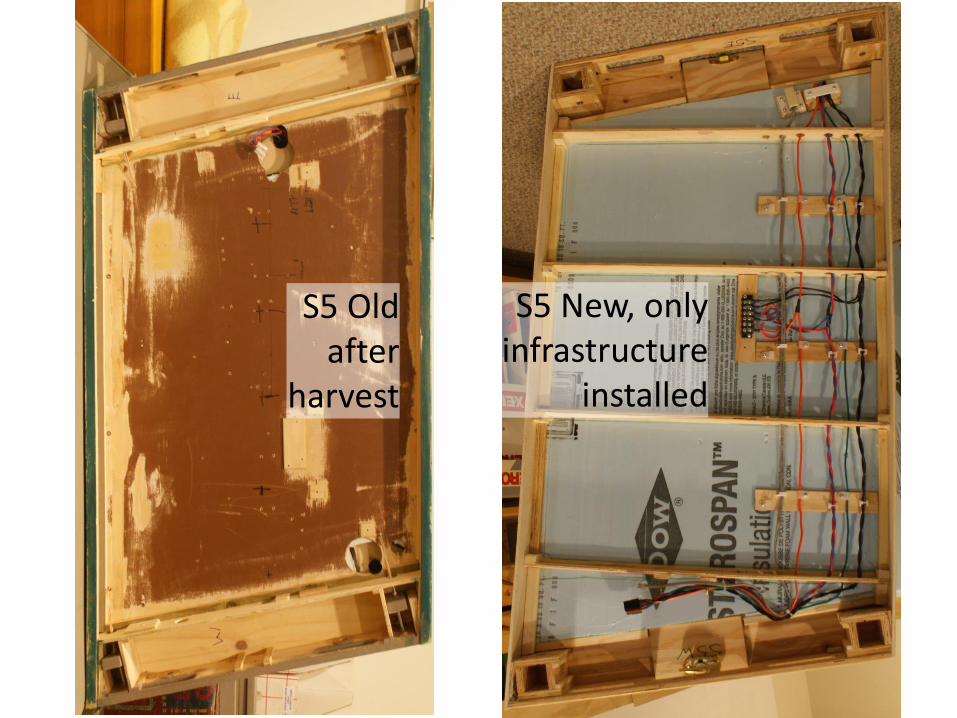
S5 Old after
harvest
S5 New, only infrastructure
installed
Build (1)
Sequence of assembly makes the difference in construction difficulty
• Ends built first in matching pairs
– Cut and route end plates for handholds and latches
– Drill end plate pairs together and install alignment dowels (mark pairs!)
– Assemble end plate to top, leg pockets, and latch base plate
– Install cam latches for sections

Top View of section end assemblies – Sections Joined End structures are assembled first, then sides are added on assembly fixture which holds everything square
Bottom View – Sections Joined End assemblies are constructed as matching ends with all glued joints End plates are ½” ply routed and drilled on a template Tops are ¼” ply Leg pockets are ½” ply Knob is leg securing clamp – one of four knobs installed
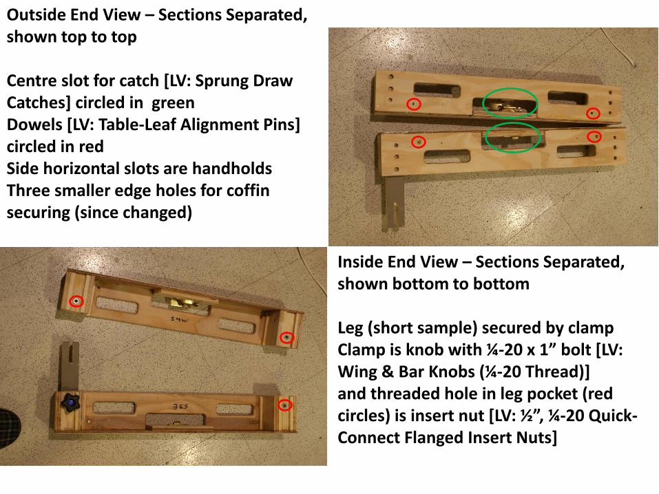
Inside End View – Sections Separated, shown bottom to bottom Leg (short sample) secured by clamp Clamp is knob with ¼-20 x 1” bolt [LV: Wing & Bar Knobs (¼-20 Thread)] and threaded hole in leg pocket (red circles) is insert nut [LV: ½”, ¼-20 Quick-Connect Flanged Insert Nuts]
Outside End View – Sections Separated, shown top to top Centre slot for catch [LV: Sprung Draw Catches] circled in green Dowels [LV: Table-Leaf Alignment Pins] circled in red Side horizontal slots are handholds Three smaller edge holes for coffin securing (since changed)

Pins/ Cam Latch Joining Sections
Alignment Pins
Latch Lever
Latch Hook
Latch Closed

Build (2) • Assemble Module/ Section
– Attach sides using assembly fixture
– End profiles shaped as a pair (trio)
– Install end profiles
– Use one section as jig for next

Adding sides on assembly fixture with previous section as jig
Assembly fixture allows precise leveling and provides clamping surfaces
Build (3) • Install Electrical Infrastructure
• Add sub-roadbed and track – Set up section pairs, attached and level – Add sub-roadbed – Note use of lightweight beam structure – sound isolation – Add roadbed – Install track across joints – Use PC ties to ensure robustness – Cut track and PC ties – File chamfers on rails
• Electrical – Install feeders and other electrical elements
• Scenery – Add scenery and cut fascia profiles

Sub-Roadbed
S3
S4
S5
T-Beam (2” x 3/16” Ply web and flange) supported on end plates
Bridge abutments and piers supported on removable 3 1/2” x 3/16” Ply strip made rigid by aluminium channel on bottom, supported on end plates
Every section is different!!!
(but end structures may
be the same)

S5 Old S5 New, before track and scenery
Access to proper tools required • Regular Tools
– Table saw
– Cross compound or chop saw
– Drill press
– Router with top/ bottom guided bits
– Clamps (lots of them)
– Squares/ Right Angle clamping fixtures
• Special Tools – Routing jig (for end handholds and latch holes)
– Drilling jigs (for dowels, end plates, and coffins)
– Assembly fixture (for ensuring flatness and perpendicular surfaces when gluing)
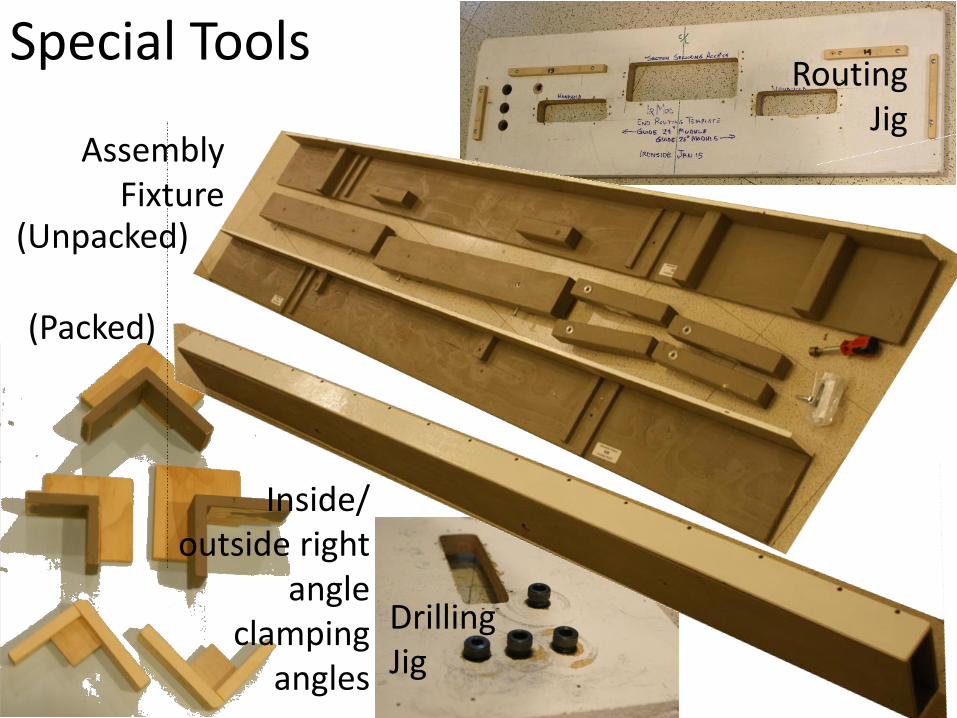
Special Tools Routing
Jig
Drilling Jig
(Packed)
(Unpacked)
Assembly Fixture
Inside/ outside right
angle clamping
angles

Assembly Clamp and
wait then
Clamp and wait

Coffin
As flatpack
Assembled Ten
minutes later

Modified End Plate/ Coffin Attachment
Bolts 1
3
2
Coffin
Protective End Plate
Section End Plate
Section End Plate to Protective End Plate Coffin Added - Internal Coffin Added - External
1 2 3
Peg Hole in Section
End Plate
1
Prototype- Handholds
not cut
Three bolts per end vs six bolts per end
Peg Peg

Weight Comparison • Old section measured
weight
– S1 (4 feet): TBD
– S2 (4 feet): 13100g
– S3 (4 feet): 14100g
– S4 (4 feet): 17415g
– S5 (4 feet): 12700g
– S6 (1 foot): 4855g
– S7 (2 feet): 8600g
• Predicted weight
/% Reduction
– 6100g/ TBD
– 7300g/ -44%
– 7000g/ -50%
– 8200g/ -53%
– 6500g/ -49%
– 3300g/ -17%
– 5000g/ -42%
Predicted weight based on measurement of unfinished section, and addition of same weight for electrical as in old
section, plus ~500g per foot for scenery. Weight reduction does not include legs or coffin

Material Densities
Material Size
Weight
Grams Unit
Pine/ Fir Strip ¼” Sq 1 in
Pine/ Fir Strip ½” Sq 4 in
Pine/ Fir Strip ¾” Sq 9 in
Pine/ Fir Strip ¾” x 1.5” 18 in
Pine/ Fir Strip ¾” x 2.5” 29 in
Pine/ Fir Strip ¾” x 3.5" 36 in
Pine/ Fir Strip 1.5" Sq 10 in
Ply Fir 1/2" 5 in2
Ply Birch 3/4" 7.5 in2
Ply Fir 1/4" 2.5 in2
Ply Pine 3/16" 2 in2
Foam Expanded 1/2" 0.22 in2
Foam Expanded 1" 0.43 in2
Foam Expanded 1.5" 0.65 in2
Foam Expanded 2" 0.87 in2

Examples so far
• Mike Walker – Two section, 8’ Free-mo module with 15 degree angled
ends
• Mark Wittrup – Two section, 12’ Free-mo module with 10 degree angled
ends
• Ironside – Five baseboard sections built, one angled, no track yet
– To go, both Free-mo end sections, one angled

Alternative Light Weight Approaches
Waffle Very strong, rigid More complex
The Sipping & Switching Society of N.C
FoamTop Light Durability question remains
Frank Wilhem Palouse

Conclusions • Lightweight but robust modules possible
• Use structure, not mass, for strength
• Approach neither trivial nor fast
• Major benefits:
– Alignment (but does not require lightweight structure)
– Portability/ ease of setup
• Unverified factors
– Long term stability
– Noise isolation

Finger Poking Time • Section 5 Old Design
– Ogden Road Truss Bridge Mock-up – Offset angle to move track from near edge (2 ½”) to centre – Electrical already harvested
• Section 5 New Design – Same footprint/ purpose as old design – Offset angle to move track from near edge (4”) to centre – Electrical infrastructure installed
• Section 7 New Design – Optional substitute section (2’) for S3/S4 Timesaver (8’) – Electrical infrastructure installed – Joins to S5 West new design
• Section 6 (Free-mo; end sections only) – Joins to S5 East new design – Short (1’) section

Presentation slides will be made available on
www.calgarymodelrailway.ca/


