Lightning and Surge Protection Strategy for Instrumentation
44
Singapore Industrial Automation Association Presented by: Eric Lim LAC Power Solution Asia Pacific Pte Ltd Dr Tan SysEng Pte Ltd
-
Upload
govtech-singapore -
Category
Engineering
-
view
129 -
download
5
Transcript of Lightning and Surge Protection Strategy for Instrumentation
Singapore Industrial Automation Association
Presented by:
Eric Lim
LAC Power Solution Asia Pacific Pte Ltd
Dr Tan
SysEng Pte Ltd
2
Agenda• Introductions
• Surge 101 – The Basics of Surge Protection
– Transient Overvoltages – Causes and Effects
– How a SPD/TVSS works
– Industry Standards
• Specifying SPD’s
• Summary
• Questions

Who Needs SPDs:
• Realistically – Everyone
Hey Doc, which teeth should I floss? Just the ones you want to keep.
Surges are like termites: Either you have them now, or you’re going
to.
• Anything with electronics needs SPDs
• How can I tell if an SPD will help?
Increased run times on equipment and reduced equipment failure.
• How can I monitor for surges?
Reality: Accurately monitoring transients requires high resolution
scopes, lots of memory, high grade CTs, skilled labor, substantial
cost, and still have opportunity to not catch the problem.
Almost always less expensive to install token SPD and try it, as
opposed to bringing in test equipment
3

4
What Is a Surge/Transient?
• High amplitude, short duration overvoltage
• Can be positive or negative polarity
– Transient: > two times system’s RMS voltage
– Noise: < two times system’s RMS voltage
Transient Overvoltage –Can be thousands of volts
Millionths of second
I

5
What Causes Surges/Transients?
• Lightning
• Switching:
– Load Switching – utility & customer
• Motors, Large Loads, Faults, Fuse
Operation
– Source Switching
• Smart Grid, Gensets, PV, Wind Turbine
• Internally generated surges: ≈70%
• Externally generated surges: ≈30%
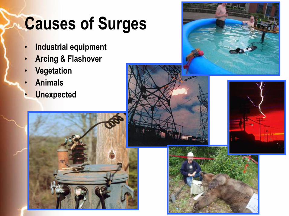
Causes of Surges• Industrial equipment
• Arcing & Flashover
• Vegetation
• Animals
• Unexpected

7
Effects of Transient Voltages?
• Microelectronics Intolerant to Surges
• Disruption
– Lockups, Downtime & Interruption costs
– Computing glitches and errors
• Degradation
– Microelectronics
– Slow & continuous damage to motor insulation
• Destruction
– Failed microelectronics, ballasts,
motors, controllers, etc.

8
Surge Suppressors• A SPD, TVSS or Surge Suppressor will Not effectively
control:
– Utility “swells” lasting several cycles
– Utility “sags”
– Harmonics
– Certain noise problems
– Not a substitute for Lightning Protection System
– Will not save energy or lower utility billing
9
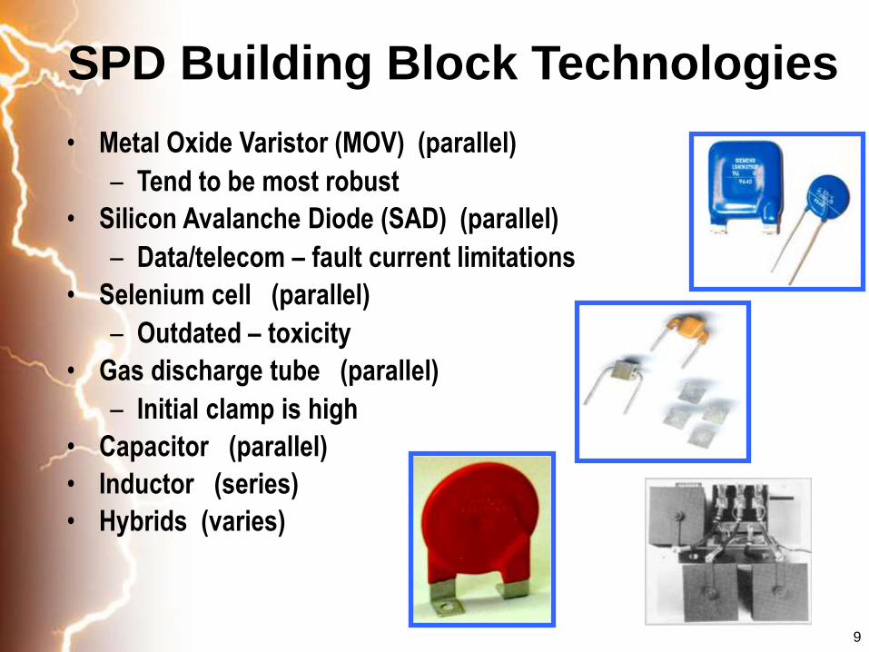
SPD Building Block Technologies
• Metal Oxide Varistor (MOV) (parallel)
– Tend to be most robust
• Silicon Avalanche Diode (SAD) (parallel)
– Data/telecom – fault current limitations
• Selenium cell (parallel)
– Outdated – toxicity
• Gas discharge tube (parallel)
– Initial clamp is high
• Capacitor (parallel)
• Inductor (series)
• Hybrids (varies)
10
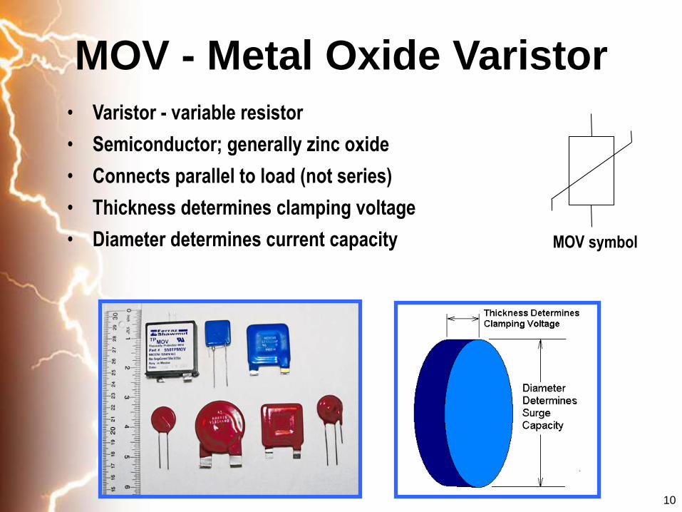
MOV - Metal Oxide Varistor
• Varistor - variable resistor
• Semiconductor; generally zinc oxide
• Connects parallel to load (not series)
• Thickness determines clamping voltage
• Diameter determines current capacity MOV symbol
11
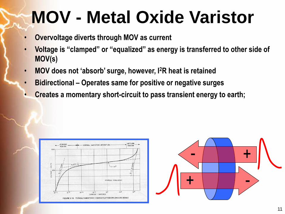
MOV - Metal Oxide Varistor • Overvoltage diverts through MOV as current
• Voltage is “clamped” or “equalized” as energy is transferred to other side of
MOV(s)
• MOV does not ‘absorb’ surge, however, I2R heat is retained
• Bidirectional – Operates same for positive or negative surges
• Creates a momentary short-circuit to pass transient energy to earth;
+-
+ -

12
SPD/TVSS Terminology• Let-through voltage, clamping voltage, suppressed voltage, measured
limiting voltage (measured in Vpeak)
• Surge current, peak-amp current, maximum current, (measured in
Imax)
• MCOV - Maximum Continuous Operating Voltage of the electrical
system (measured in Vrms)
Load
Surge Current
(thru SPD)
MOV/SPD
Clamping or
Let-Through
Voltage
MCOV
13
SPD/TVSS Terminology
MCOV
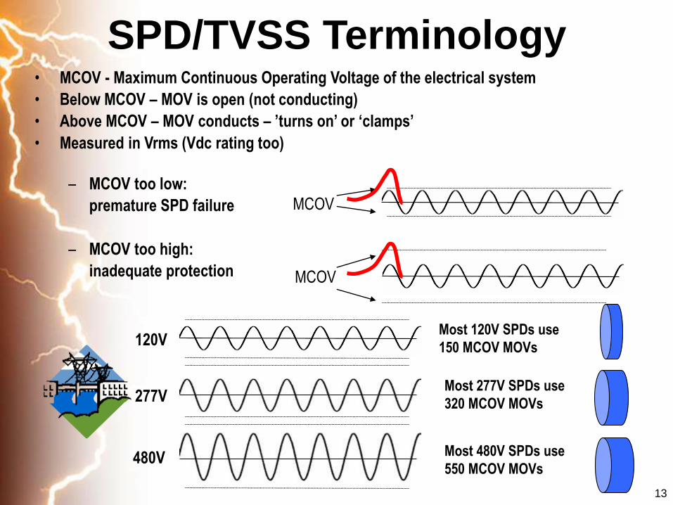
Most 120V SPDs use
150 MCOV MOVs
Most 277V SPDs use
320 MCOV MOVs
Most 480V SPDs use
550 MCOV MOVs
MCOV
120V
277V
480V
• MCOV - Maximum Continuous Operating Voltage of the electrical system
• Below MCOV – MOV is open (not conducting)
• Above MCOV – MOV conducts – ’turns on’ or ‘clamps’
• Measured in Vrms (Vdc rating too)
– MCOV too low:
premature SPD failure
– MCOV too high:
inadequate protection
14
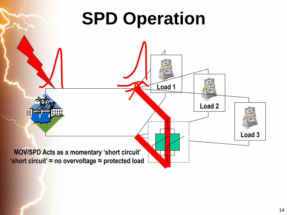
SPD Operation
MOV/SPD Acts as a momentary ‘short circuit’
‘short circuit’ ≈ no overvoltage ≈ protected load
Load 1
Load 2
Load 3
15
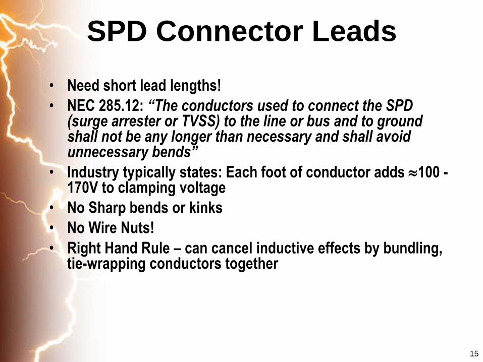
SPD Connector Leads
• Need short lead lengths!
• NEC 285.12: “The conductors used to connect the SPD (surge arrester or TVSS) to the line or bus and to ground shall not be any longer than necessary and shall avoid unnecessary bends”
• Industry typically states: Each foot of conductor adds 100 -170V to clamping voltage
• No Sharp bends or kinks
• No Wire Nuts!
• Right Hand Rule – can cancel inductive effects by bundling, tie-wrapping conductors together

16
Modes of Protection
• MOVs equalize potential
across either side of MOV
• Various ways to connect MOVs
• IEEE recommends defining modes: L-N, L-G, N-G, etc. (because ‘Common Mode’ and ‘Normal Mode’ mean different things to different folks)

17
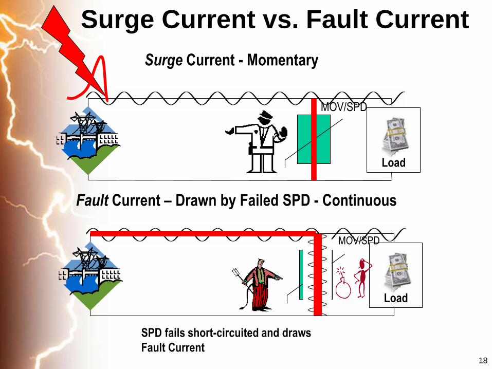
SPD/TVSS Terminology
• Surge Current
– Normal operation - Current through MOV/SPD while conducting a surge – tends to be momentary
• Fault Current
– Failure condition - Current through MOV/SPD when it has failed in a short-circuit condition – tends to be continuous
• Two totally different currents
• A transient doesn’t know if its entering 4,000A switchgear or a 100A panel.
• Fault current is based on the distribution system, not surge transient.
18
Surge Current vs. Fault Current
Load
MOV/SPD
Surge Current - Momentary
MOV/SPD
Fault Current – Drawn by Failed SPD - Continuous
SPD fails short-circuited and draws
Fault Current
Load

19
Standards, Codes, Practices, and
Guidelines for Low Voltage SPDs
• IEEE Trilogy
– C62.41.1 & C62.41.2 - 2002 Best Practices
– C62.45 - 2002 Test Procedures
• Importance of UL 1449
– Safety & failure testing
– Performance testing - clamping voltage and pulse life
– Third Edition, Second Edition Revision, Second Edition
• USA National Electrical Code 2002, 2005 & 2008
• IEC EN61000-4-4 & EN61000-4-5
• CP33 ???

20
Flash Density: Flashes/km2/year
21
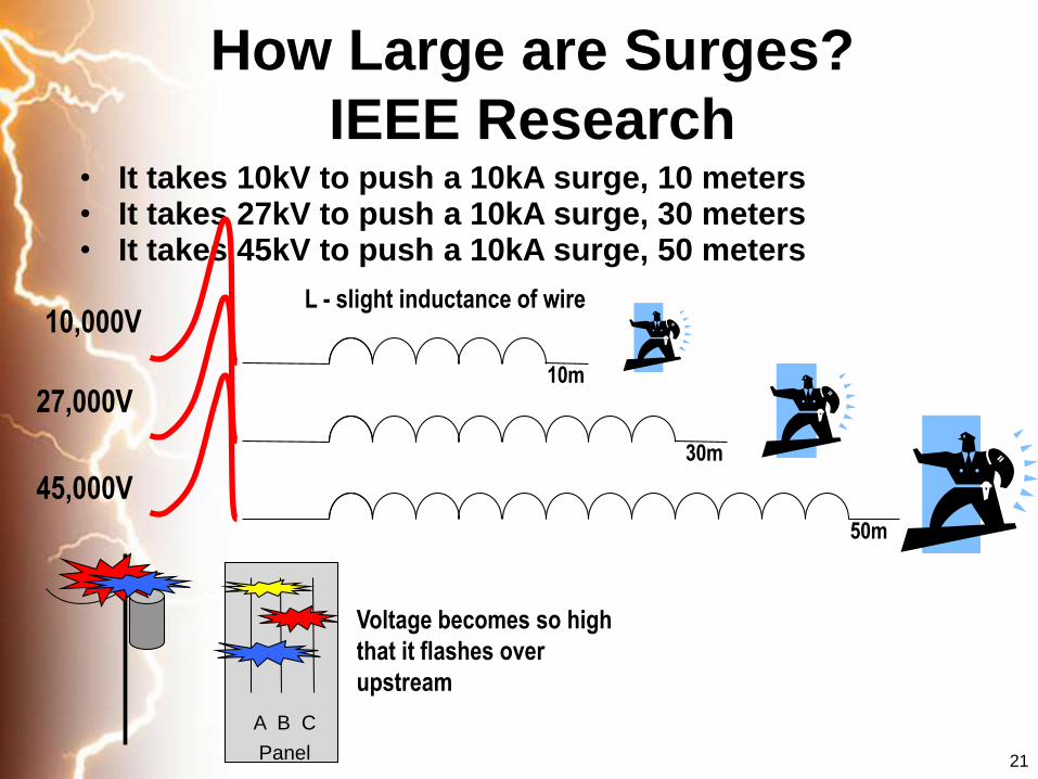
• It takes 10kV to push a 10kA surge, 10 meters• It takes 27kV to push a 10kA surge, 30 meters• It takes 45kV to push a 10kA surge, 50 meters
Voltage becomes so high
that it flashes over
upstream
10,000V
27,000V
45,000V
A B C
Panel
L - slight inductance of wire
10m
30m
50m
How Large are Surges?
IEEE Research

22
IEEE C62.41.2 - 2002“Expected voltages and current surges”
Location Categorya
Peak Valuesd Effective Impedance ()
Voltage(kV)
Current(kA)
A 6 0.5 12f
B 6 3 2
Table 3 – Standard 1.2/50s – 8/20s Combination Wave
Expected voltages and current surges in Location Categoriesa A and Bb
Single-phase modesc : L-N, L-G and [L&N]-G
Polyphase modes: L-L, L-N, L-G and [L’s]-G
(See Table 5 for N-G modes)
Table 4 – Scenario I tests for SPDs intended for Location Category C3
Exposure
Standard tests Optional test
1.2/50µs Voltage generator 8/20µs Current generator
100kHz Ring Wave for front-of-wave response
evaluationMinimum open-circuit voltage
to be applied to SPDCurrent to be driven through
the SPDb
Low 6kV 3kAc 6kV
High 10kV 10kA 6kV
23
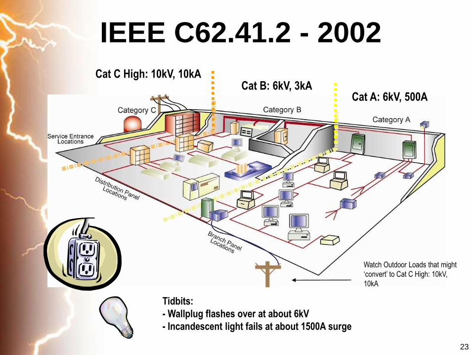
IEEE C62.41.2 - 2002
Cat C High: 10kV, 10kACat B: 6kV, 3kA
Cat A: 6kV, 500A
Tidbits:
- Wallplug flashes over at about 6kV
- Incandescent light fails at about 1500A surge
Watch Outdoor Loads that might
‘convert’ to Cat C High: 10kV,
10kA

24
Cascade Protection
Trans
Meter
Svc.
Disc.
Panel
10m (30feet)
25
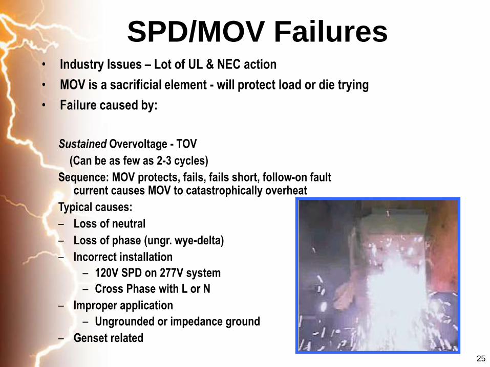
SPD/MOV Failures• Industry Issues – Lot of UL & NEC action
• MOV is a sacrificial element - will protect load or die trying
• Failure caused by:
Sustained Overvoltage - TOV
(Can be as few as 2-3 cycles)
Sequence: MOV protects, fails, fails short, follow-on fault current causes MOV to catastrophically overheat
Typical causes:
– Loss of neutral
– Loss of phase (ungr. wye-delta)
– Incorrect installation
– 120V SPD on 277V system
– Cross Phase with L or N
– Improper application
– Ungrounded or impedance ground
– Genset related
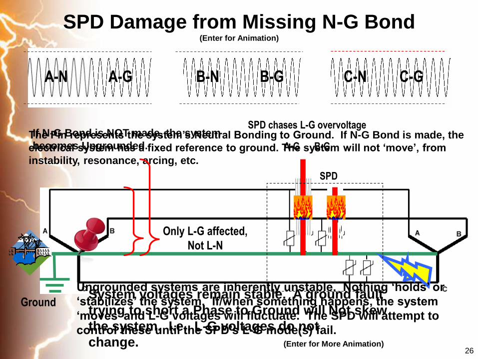
A-G B-G C-GA-N B-N C-N
Ground
SPD chases L-G overvoltage
A-G B-G
SPD Damage from Missing N-G Bond(Enter for Animation)
Only L-G affected,
Not L-N
26
The Pin represents the system’s Neutral Bonding to Ground. If N-G Bond is made, the
electrical system has a fixed reference to ground. The system will not ‘move’, from
instability, resonance, arcing, etc.
System voltages remain stable. A ground fault
trying to short a Phase to Ground will Not skew
the system. I.e., L-G voltages do not
change. (Enter for More Animation)
If N-G Bond is NOT made, the system
becomes Ungrounded.
SPD
Ungrounded systems are inherently unstable. Nothing ‘holds’ or
‘stabilizes’ the system. If/when something happens, the system
‘moves’ and L-G voltages will fluctuate. The SPD will attempt to
control these until the SPD’s L-G mode(s) fail.

27
Typical Sequence of SPD Failure
Load
MOV/SPD
If extremely rapid
overheat, and ruptureIf overheats ‘slowly’
– can catch fire
System level Sustained Overvoltage – TOV Voltage exceeds MCOV – as little as 2-3 cycles
MOV fails towards short circuit
Follow-on/fault current causes MOV to catastrophically overheat

UL 1449
• UL 1449 is the industry safety standard
• End of life testing
– Why? SPD/MOV failure
• Assigns performance ratings for comparison
• UL 1449 Second Edition effective Aug 98
• UL 1449 Second Edition Revision adds Intermediate Fault Current
testing, released and effective Feb 07
• UL 1449 Third Edition released & effective Sept 09
28

UL 1449 THIRD Edition
SPD
TVSSSurge
Arresters
• New SPD Types: Types 1, 2, 3 & 4
• New Voltage Protection Ratings (VPRs) replace
old-style Suppressed Voltage Ratings (SVRs)
• New I nominal ratings
• Bid Specifications become Obsolete as product
evaluation & ratings change
(Major huge expensive big deal to manufacturers!)
Combine TVSS and Surge Arresters into one UL
Standard, UL 1449 3rd Edition renamed:
Surge Protective Devices (SPDs)
Effective: Sept 29, 2009
29


UL 1449-3Nominal Discharge Current Testing – I nominal, InNew Concept to USA – Originated from IEC 61643
- Duty Cycle Testing
- 15 8x20s surges through every mode of three samples used for VPR
testing
Type 1 – 20kA or 10kA
Type 2 – 20kA, 10kA, 5kA or 3kA
Type 3 – 3kA
Type 4 – Based on intended usage as Types 1, 2 or 3
UL 96A Master Label requires 20kA In from Type 1 or Type 2
SPD
32
33
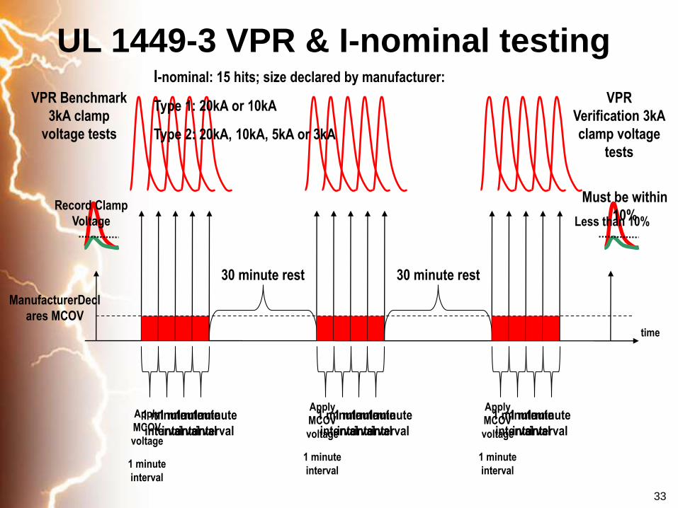
UL 1449-3 VPR & I-nominal testing
time
VPR Benchmark
3kA clamp
voltage tests
30 minute rest
Apply
MCOV
voltage
1 minute
interval
1 minute
interval
1 minute
interval
1 minute
interval
1 minute
interval
ManufacturerDecl
ares MCOV
Record Clamp
Voltage
30 minute rest
Apply
MCOV
voltage
1 minute
interval
1 minute
interval
1 minute
interval
1 minute
interval
1 minute
interval
Apply
MCOV
voltage
1 minute
interval
1 minute
interval
1 minute
interval
1 minute
interval
VPR
Verification 3kA
clamp voltage
tests
Must be within
10%
I-nominal: 15 hits; size declared by manufacturer:
Type 1: 20kA or 10kA
Type 2: 20kA, 10kA, 5kA or 3kA
Less than 10%

EMC Directive 89/336/EC
Immunity to Fast Transients
• EN61000-4-4
• The Severity Level depends on the
environment.
• The equipment tested must not show
any change in its normal operation .

• Test levels for burst tests
Level mains supply lines I/O lines
1 500V 5kHz 250V 5kHz
2 1000V 5kHz 500V 5kHz
3 2000V 5kHz 1000V 5kHz
4 4000V 2.5kHz 2000V 5kHz
Test Levels

Immunity to Lightning Transients
• EN61000-4-5
• The Severity Level depends on the
environment.
• The equipment tested must not show
any change in its normal operation .

Immunity to Lightning Transients
Severity
Class
Test Voltage Environment
1 0,5K V Highly Protected
2 1 KV Protected
3 2 KV Normal Industry
4 4 KV Heavy Industry
X Especial Special Locations

IEC vs. UL and IEEE• Promotes the 10x350 impulse
– Evolved from a 10 Coulomb charge
– Uses ramp up or pre-conditioning test
• IEC believes 100% of lighting can enter a building and go through wire
• IEC says grounding is different and overhead lines are more vulnerable to lightning
• More concerned with protecting the switch gear not sensitive equipment
• 10x350 waves requires a different technology
– Spark gap type arrestors
– Questionable clamping and protective abilities
• Promotes the 8X20 impulse
– No pre-conditioning
– Just “whack” it with the
surge
• IEEE say natural inductance of
wire limits surges
• Lightning Protection and Surge
Protection are cousins, not
brothers
• More concerned with protection
sensitive equipment along with
the switchgear
• IEEE and UL SPDs tend to clamp
lower
38

IEC vs. UL and IEEE
• There is great debate on IEC vs. IEEE
– Politics coming into play??
• IEC’s 10x350 wave is >700 times larger than IEEE experiences
– IEEE may be off by a little but not 700X!
• Spark Gap IEC units can handle a lot of energy
– Moving surge current is not the same as clamping low enough to
protect loads, ex. Clamping voltage could be 1000++ volts
– Load dies while SPD survives
• North American UL only cares about safe failure
– European surge manufacturers have difficulty passing UL
– Safety aspects are far behind UL
• The debate is not likely to end anytime soon…
39
40
• Could be Biggest Myth in all of Surge Suppression
• Tends to falsely imply protection from events not demonstrated to occur
– IEEE: surge amplitude is limited
• Driven by Marketing:
– Used for spec posturing to exclude safer SPDs from specs
– Creates aura for needing larger SPDs. When LS-1 was written in 1992, a big TVSS was 30kA; now 500kA-1000kA
• Moving surge current not the same as reducing voltage to a survivable level
• Tests purposely do not show 10,000 – 20,000V clamping voltages.
– Most folks would figure out load died at least 9,000V ago
• Few grounding systems can ‘earth’ claimed ratings
• Can argue that fusing compromises associated with Single Impulse led to safety problems resulting in UL and NEC actions.
Single Impulse Testing

42
Applying SPDs
• Effective Facility Protection - Factors to Consider
• Positively ID the Electrical System (480V 3phase isn’t enough)
• Proximity on Electrical Grid
• Proximity in Facility (Service is different than downstream)
• Modes of Protection
• Cascading SPDs
• Locating & Placement of Suppressors
• Grounding/Bonding SPDs
• Installed Clamping Voltage (Short Leads)
• Redundancy = Longevity (kA ratings for redundancy & longer life – to a point)
• Power + phone/data/network = Complete Protection

43
Factors to Consider
• Utility Service
– Overhead or Underground
– Line Switching / Cap Banks
– End of Line (transmission line effects & reflection)
• Structure Location
– Height
– Rural / Urban
• Facility Equipment
– Expense to Repair
– Mission Critical
– Sensitive
Voltage
momentarily
doubles at
end of line
44
Thank you for your time