Lightnin 70-80 Gear Drive Maintenance 2-7 Size
13
REVISION 2002 DATE 5–15–85 REVISED 3–19–04 PAGE 1 OF 13 INST. NO. IT–2129 F © LIGHTNIN LIGHTNIN MIXERS AND AERATORS ® GEAR DRIVE MAINTENANCE INSTRUCTIONS 70 & 80 SERIES MODELS – UNIT SIZES 2 THRU 7 80 SERIES LOW SPEED SHAFT CONSTRUCTION 70 SERIES LOW SPEED SHAFT CONSTRUCTION LUBRICANT FITTING – UPPER BEARING SHIM PACK (417) (FOR SETTING AXIAL DIPSTICK (20) BREATHER ASS’Y. (21) CHANGE GEAR PINION (210) BEVEL PINION CHANGE GEAR (212) CHANGE GEAR HEX HEAD CAP SCREWS LOW SPEED SHAFT (402) OIL SEAL (411) GREASE PACK IN ASSEMBLY HEX HEAD CAP SCREWS (413) BEVEL GEAR (100) HEX HD. CAP SCREWS (25) HIGH SPEED SHAFT (201) OUTER HEX HEAD CAP SCREWS (422) GASKET (28) SHIM PACK (412) (FOR SETTING BEVEL NOTE 1 SEE TABLES 4 & 5 FOR TIGHTENING TORQUES 1 1 1 1 1 (217) COVER (216) COVER GASKET (215) COVERPLATE (27) BEARING FLOAT) GREASE PACK IN ASSEMBLY BEARING (205) GREASE LUBRICATED MODELS 74/84 THRU 77/87 ONLY GEAR BACKLASH) LOWER BEARING GREASE LUBRICATED & SHAFT (101) SEAL COLLAR (403) PACK RETAINER WITH GREASE OIL LEVEL FIGURE 1 – TYPICAL DOUBLE REDUCTION UNIT SIZE 2 THRU 6 GEAR DRIVE ILLUSTRATED HEX HEAD CAP SCREWS 1 (111) SECTION 1 – GENERAL WARNING: EYE PROTECTION MUST BE WORN AT ALL TIMES WHILE SERVICING THIS MIXER. WARNING: DISCONNECT MOTOR LEADS OR OTHERWISE LOCK–OUT POWER SUPPLY BEFORE SERVICING THIS MIXER. 1.1 Model 70 & 80 Series Gear Drives are precision manufactured and assembled to provide long trouble–free service when properly maintained. If it becomes necessary to disassemble the unit, careful precise re–assembly is necessary. Provided by G&W Industrial Sales 304-422-4755 [email protected]
-
Upload
arturo-suzan -
Category
Documents
-
view
30 -
download
2
description
Manual de reparacion y servicio agitador para lodos 70 80
Transcript of Lightnin 70-80 Gear Drive Maintenance 2-7 Size
REVISION
2002
DATE 5–15–85
REVISED 3–19–04 PAGE 1 OF 13
INST. NO. IT–2129F
© LIGHTNINLIGHTNINMIXERS AND AERATORS
®
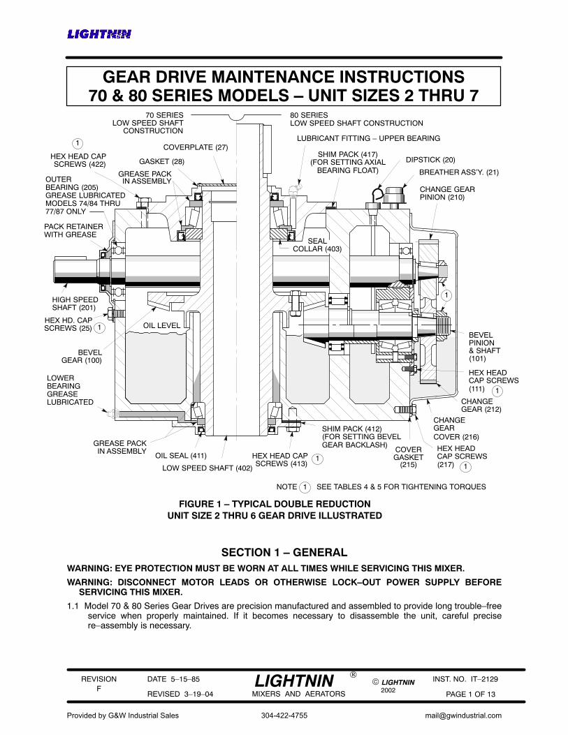
GEAR DRIVE MAINTENANCE INSTRUCTIONS70 & 80 SERIES MODELS – UNIT SIZES 2 THRU 7
80 SERIESLOW SPEED SHAFT CONSTRUCTION
70 SERIESLOW SPEED SHAFT
CONSTRUCTIONLUBRICANT FITTING – UPPER BEARING
SHIM PACK (417)(FOR SETTING AXIAL DIPSTICK (20)
BREATHER ASS’Y. (21)
CHANGE GEARPINION (210)
BEVELPINION
CHANGEGEAR (212)
CHANGE GEAR
HEX HEADCAP SCREWS
LOW SPEED SHAFT (402)
OIL SEAL (411)
GREASE PACKIN ASSEMBLY
HEX HEAD CAPSCREWS (413)
BEVELGEAR (100)
HEX HD. CAPSCREWS (25)
HIGH SPEEDSHAFT (201)
OUTER
HEX HEAD CAPSCREWS (422) GASKET (28)
SHIM PACK (412)(FOR SETTING BEVEL
NOTE 1 SEE TABLES 4 & 5 FOR TIGHTENING TORQUES
1
1
1
1
1
(217)
COVER (216)
COVERGASKET
(215)
COVERPLATE (27)
BEARING FLOAT)GREASE PACKIN ASSEMBLY
BEARING (205)GREASE LUBRICATEDMODELS 74/84 THRU77/87 ONLY
GEAR BACKLASH)
LOWERBEARINGGREASELUBRICATED
& SHAFT(101)
SEALCOLLAR (403)
PACK RETAINERWITH GREASE
OIL LEVEL
FIGURE 1 – TYPICAL DOUBLE REDUCTIONUNIT SIZE 2 THRU 6 GEAR DRIVE ILLUSTRATED
HEX HEADCAP SCREWS
1(111)
SECTION 1 – GENERALWARNING: EYE PROTECTION MUST BE WORN AT ALL TIMES WHILE SERVICING THIS MIXER.
WARNING: DISCONNECT MOTOR LEADS OR OTHERWISE LOCK–OUT POWER SUPPLY BEFORESERVICING THIS MIXER.
1.1 Model 70 & 80 Series Gear Drives are precision manufactured and assembled to provide long trouble–freeservice when properly maintained. If it becomes necessary to disassemble the unit, careful precisere–assembly is necessary.
Provided by G&W Industrial Sales
304-422-4755
REVISION
2002
DATE 5–15–85
REVISED 3–19–04 PAGE 2 OF 13
INST. NO. IT–2129F
© LIGHTNINLIGHTNINMIXERS AND AERATORS
®
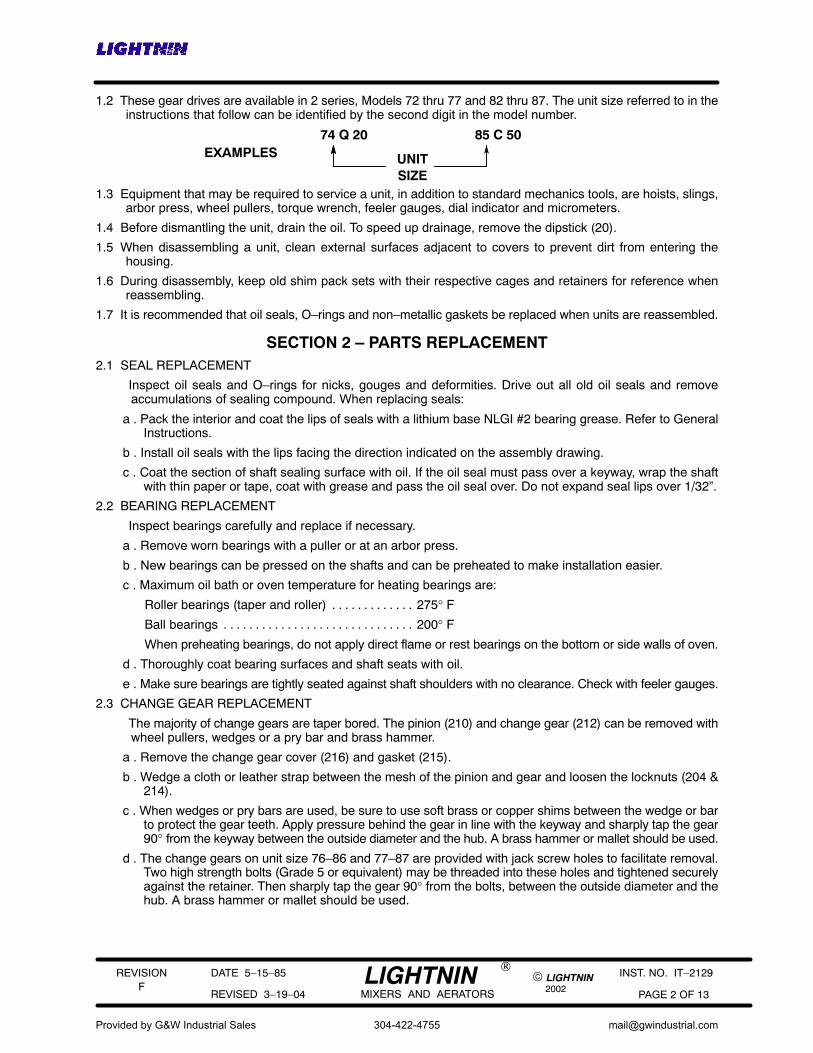
1.2 These gear drives are available in 2 series, Models 72 thru 77 and 82 thru 87. The unit size referred to in theinstructions that follow can be identified by the second digit in the model number.
EXAMPLES74 Q 20 85 C 50
UNITSIZE
1.3 Equipment that may be required to service a unit, in addition to standard mechanics tools, are hoists, slings,arbor press, wheel pullers, torque wrench, feeler gauges, dial indicator and micrometers.
1.4 Before dismantling the unit, drain the oil. To speed up drainage, remove the dipstick (20).
1.5 When disassembling a unit, clean external surfaces adjacent to covers to prevent dirt from entering thehousing.
1.6 During disassembly, keep old shim pack sets with their respective cages and retainers for reference whenreassembling.
1.7 It is recommended that oil seals, O–rings and non–metallic gaskets be replaced when units are reassembled.
SECTION 2 – PARTS REPLACEMENT2.1 SEAL REPLACEMENT
Inspect oil seals and O–rings for nicks, gouges and deformities. Drive out all old oil seals and removeaccumulations of sealing compound. When replacing seals:
a . Pack the interior and coat the lips of seals with a lithium base NLGI #2 bearing grease. Refer to GeneralInstructions.
b . Install oil seals with the lips facing the direction indicated on the assembly drawing.
c . Coat the section of shaft sealing surface with oil. If the oil seal must pass over a keyway, wrap the shaftwith thin paper or tape, coat with grease and pass the oil seal over. Do not expand seal lips over 1/32”.
2.2 BEARING REPLACEMENT
Inspect bearings carefully and replace if necessary.
a . Remove worn bearings with a puller or at an arbor press.
b . New bearings can be pressed on the shafts and can be preheated to make installation easier.
c . Maximum oil bath or oven temperature for heating bearings are:
Roller bearings (taper and roller) 275° F. . . . . . . . . . . . .
Ball bearings 200° F. . . . . . . . . . . . . . . . . . . . . . . . . . . . . .
When preheating bearings, do not apply direct flame or rest bearings on the bottom or side walls of oven.
d . Thoroughly coat bearing surfaces and shaft seats with oil.
e . Make sure bearings are tightly seated against shaft shoulders with no clearance. Check with feeler gauges.
2.3 CHANGE GEAR REPLACEMENT
The majority of change gears are taper bored. The pinion (210) and change gear (212) can be removed withwheel pullers, wedges or a pry bar and brass hammer.
a . Remove the change gear cover (216) and gasket (215).
b . Wedge a cloth or leather strap between the mesh of the pinion and gear and loosen the locknuts (204 &214).
c . When wedges or pry bars are used, be sure to use soft brass or copper shims between the wedge or barto protect the gear teeth. Apply pressure behind the gear in line with the keyway and sharply tap the gear90° from the keyway between the outside diameter and the hub. A brass hammer or mallet should be used.
d . The change gears on unit size 76–86 and 77–87 are provided with jack screw holes to facilitate removal.Two high strength bolts (Grade 5 or equivalent) may be threaded into these holes and tightened securelyagainst the retainer. Then sharply tap the gear 90° from the bolts, between the outside diameter and thehub. A brass hammer or mallet should be used.
Provided by G&W Industrial Sales
304-422-4755

REVISION
2002
DATE 5–15–85
REVISED 3–19–04 PAGE 3 OF 13
INST. NO. IT–2129F
© LIGHTNINLIGHTNINMIXERS AND AERATORS
®
e . If removal is stubborn, apply heat evenly around the circumference of the gear hub with a torch or otherdevice, but do not allow the hub temperature to exceed 275° F. The heat should be applied quickly to thehub to prevent the shaft from heating.
f . Remove straight bore pinions from shafts at an arbor press.
g . To replace straight bore pinions, preheat to 275° F and press on shaft with large chamfered side tightagainst shaft shoulder. Check with feelers for zero clearance between shaft shoulder and pinion beforetightening locknut.
h . Some units are furnished with an integral shaft and pinion (209) (pinion teeth machined directly on shaft)for the higher ratios. Remove shaft and pinion (209) as outlined in Section 3 to change speeds.
2.4 Unit size 77–87 models require an oil pan as shown in Figure 2 for the total ratio and input speed combinationsdesignated by an ”X” in Table 1. If the unit is dismantled, make sure the oil pan is re–installed.
a . If converting to a speed and ratio which no longer requires an oil pan, remove the front half of the pan. Theadapter can remain assembled to the retainer (110).
b . If the unit was not equipped with an oil pan, and the unit is converted to a speed and ratio that requires one,an oil pan must be added.
c . For variable speed applications, an oil pan is required if either extremity of the speed range falls within theinput speeds (and ratio) shown in Table 1.
TABLE 1 – OIL PAN USAGE
UNITSIZE
INPUTRPM
NOMINAL TOTAL RATIO
6.2
77–871750
1450
7.6 9.3 11.4
FIGURE 2 – OIL PAN DETAIL
X X X X
X X
BEVEL PINION SHAFT (101)
CHANGE GEAR (212)
OIL PAN – FRONT HALF
OIL PAN ADAPTER
CHANGE GEAR COVER (216)
OIL PAN CAP SCREWS AND LOCKNUTS
MAIN HOUSING (2)
RETAINER (110)
SECTION 3 – HIGH SPEED OR (TRIPLE REDUCTION) INTERMEDIATE SHAFTREMOVAL
3.1 These shafts must be removed from the motor end of the gear drive.
3.2 DOUBLE REDUCTION – HIGH SPEED SHAFT (201 or 209) REMOVAL
a . Remove the pinion (210) to prevent damage to the gear teeth. For integral shaft and pinion (209), or pinionsthat are not removed, wrap the teeth with a strong tape prior to removal.
b . Remove the high speed seal cage (22), oil seal (23) and gasket (24). Use care so as not to damage theoil seal.
Provided by G&W Industrial Sales
304-422-4755
REVISION
2002
DATE 5–15–85
REVISED 3–19–04 PAGE 4 OF 13
INST. NO. IT–2129F
© LIGHTNINLIGHTNINMIXERS AND AERATORS
®
c . Remove high speed shaft (201) assembly from unit to provide clearance for bevel gear removal. Inspectbearings (202 & 205) and replace if necessary.
CAUTION: Proceed slowly and maneuver the shaft until the bearings clear the bevel gear (100), low speedshaft (402) and bearing cage (420).
3.3 TRIPLE REDUCTION – INTERMEDIATE SHAFT (315) REMOVAL
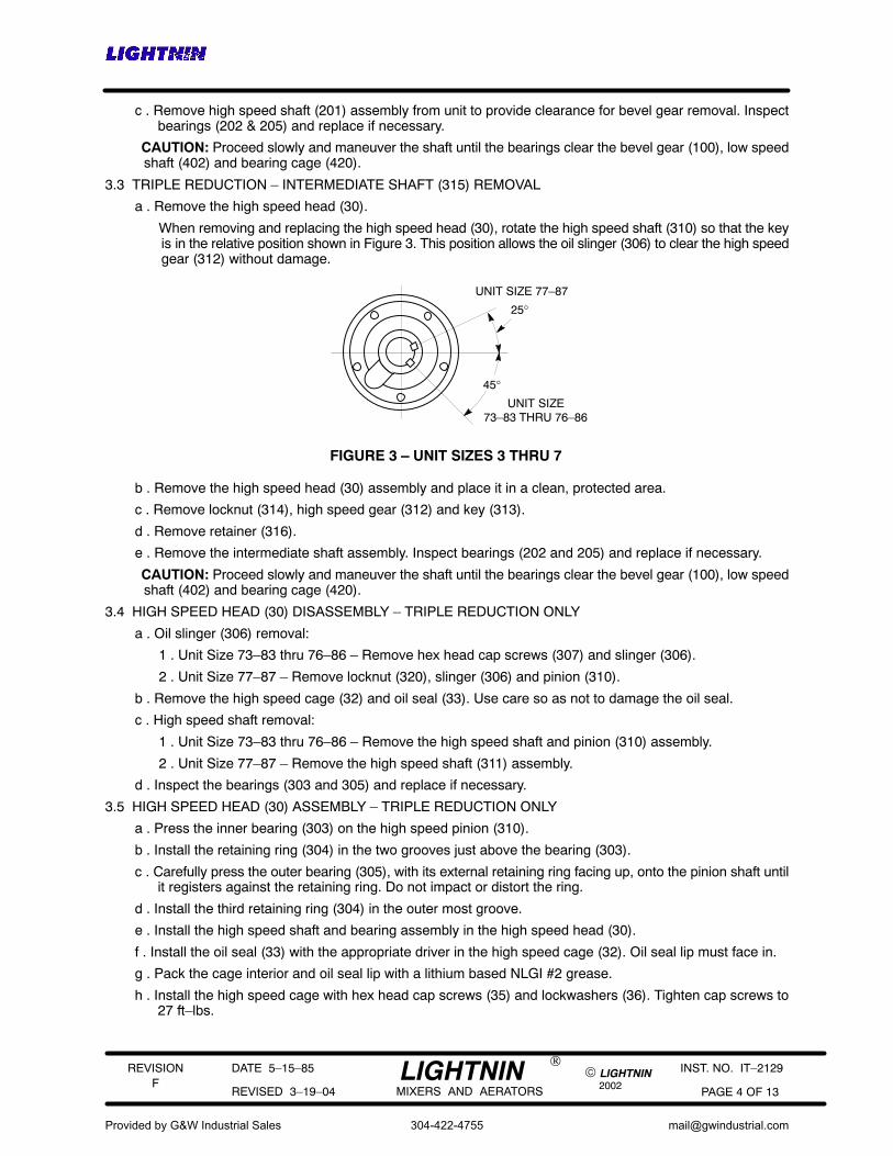
a . Remove the high speed head (30).
When removing and replacing the high speed head (30), rotate the high speed shaft (310) so that the keyis in the relative position shown in Figure 3. This position allows the oil slinger (306) to clear the high speedgear (312) without damage.
45°
25°UNIT SIZE 77–87
UNIT SIZE73–83 THRU 76–86
FIGURE 3 – UNIT SIZES 3 THRU 7
b . Remove the high speed head (30) assembly and place it in a clean, protected area.
c . Remove locknut (314), high speed gear (312) and key (313).
d . Remove retainer (316).
e . Remove the intermediate shaft assembly. Inspect bearings (202 and 205) and replace if necessary.
CAUTION: Proceed slowly and maneuver the shaft until the bearings clear the bevel gear (100), low speedshaft (402) and bearing cage (420).
3.4 HIGH SPEED HEAD (30) DISASSEMBLY – TRIPLE REDUCTION ONLY
a . Oil slinger (306) removal:
1 . Unit Size 73–83 thru 76–86 – Remove hex head cap screws (307) and slinger (306).
2 . Unit Size 77–87 – Remove locknut (320), slinger (306) and pinion (310).
b . Remove the high speed cage (32) and oil seal (33). Use care so as not to damage the oil seal.
c . High speed shaft removal:
1 . Unit Size 73–83 thru 76–86 – Remove the high speed shaft and pinion (310) assembly.
2 . Unit Size 77–87 – Remove the high speed shaft (311) assembly.
d . Inspect the bearings (303 and 305) and replace if necessary.
3.5 HIGH SPEED HEAD (30) ASSEMBLY – TRIPLE REDUCTION ONLY
a . Press the inner bearing (303) on the high speed pinion (310).
b . Install the retaining ring (304) in the two grooves just above the bearing (303).
c . Carefully press the outer bearing (305), with its external retaining ring facing up, onto the pinion shaft untilit registers against the retaining ring. Do not impact or distort the ring.
d . Install the third retaining ring (304) in the outer most groove.
e . Install the high speed shaft and bearing assembly in the high speed head (30).
f . Install the oil seal (33) with the appropriate driver in the high speed cage (32). Oil seal lip must face in.
g . Pack the cage interior and oil seal lip with a lithium based NLGI #2 grease.
h . Install the high speed cage with hex head cap screws (35) and lockwashers (36). Tighten cap screws to27 ft–lbs.
Provided by G&W Industrial Sales
304-422-4755
REVISION
2002
DATE 5–15–85
REVISED 3–19–04 PAGE 5 OF 13
INST. NO. IT–2129F
© LIGHTNINLIGHTNINMIXERS AND AERATORS
®
i . Install the slinger (306):
1 . Unit size 73–83 thru 76–86 – Install the slinger (306) with hex head cap screws (307).
2 . Unit size 77–87 – Install the high speed pinion (310), slinger (306) and locknut (320). Tighten the locknutto the value shown in Table 5.
SECTION 4 – BEVEL SET REMOVAL AND ASSEMBLY4.1 BEVEL GEAR REMOVAL
a . The high speed shaft (201) assembly / intermediate shaft (209) assembly must be removed from unit toprovide clearance for bevel gear removal.
b . Remove the cap screws (422) from the low speed bearing cage (420). Install 2 eyebolts and lift cagestraight up. Use caution so as not to damage the oil seal (415 and 416) lips. Inspect the oil seals andbearing (404) cup. Remove if necessary.
c . Wrap and interlock two web straps around the low speed shaft (402) directly below the seal collar (403)and carefully lift the shaft out.
d . Remove the low speed retainer (410) and shims (412). Inspect oil seal (411) and replace if necessary.
e . Remove the bevel gear (100) from the low speed shaft (402).
1 . For units 72–82 and 73–83 – Press the bevel gear off the shaft.
2 . For units 74–84 thru 77–87 – Remove the cap screws (405) by restraining the locknuts and removethe gear.
f . Inspect bearings (404 and 408) and replace if necessary.
4.2 BEVEL PINION REMOVAL
CAUTION: DO NOT USE POWER WRENCHES ON NYLOK CAP SCREWS OR JACKING SCREWS.
a . Remove the outer set of cap screws (111) in the retainer (110).
b . Insert jacking screws in the retainer (110) and remove the bevel pinion assembly.
c . Remove the inner set of cap screws (111) and the retainer (110).
d . Remove the outer bearing cup (105) by pushing the bearing cage (107) inward.
e . Models 76–86 only: Remove O–ring (29).
f . Remove the locknut and washer (106).
g . Press the bearings (102 and 105) off the shaft.
CAUTION: Unit sizes 6 and 7 are furnished with a double row taper roller bearing (Item 102) that is fitted witha custom spacer, ground to provide a specific end play clearance for each individual bearing. DO NOTsubstitute spacers or interchange any components of the bearing set.
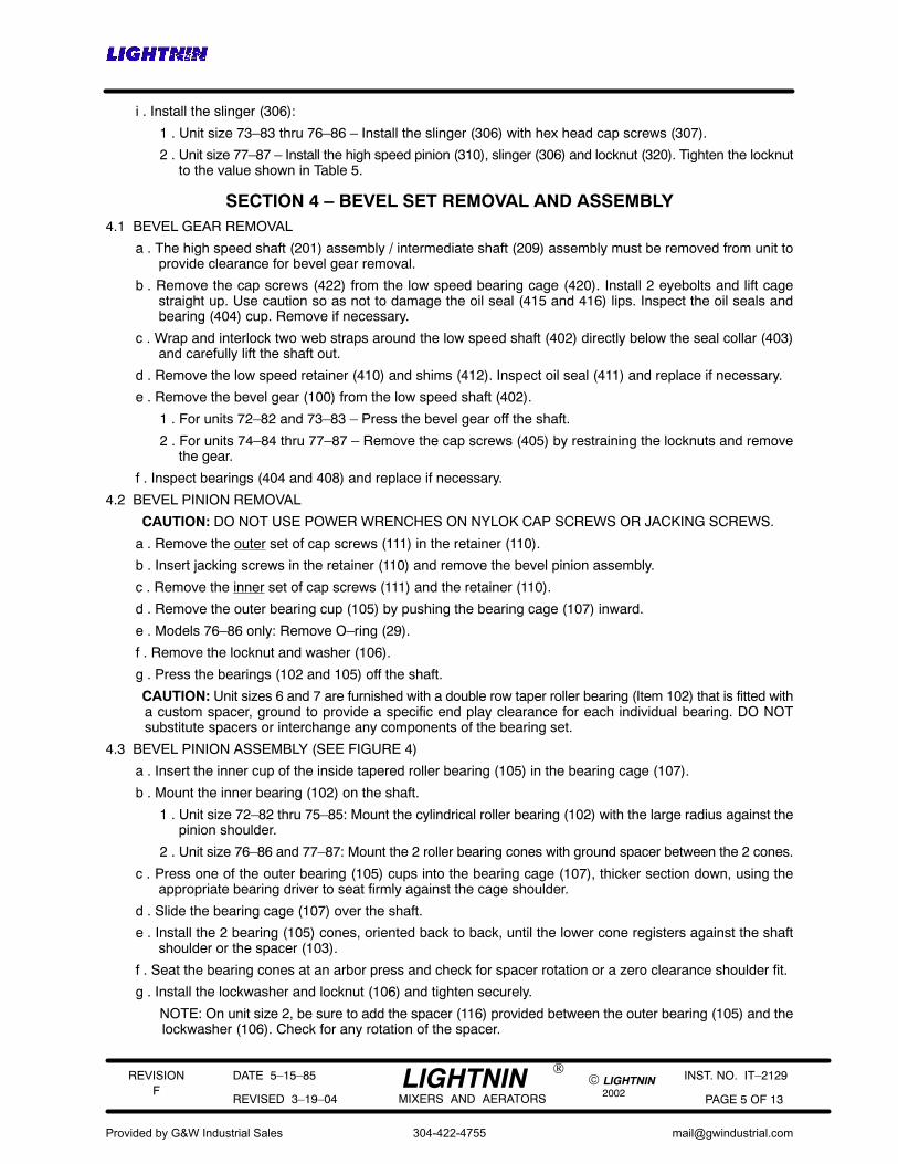
4.3 BEVEL PINION ASSEMBLY (SEE FIGURE 4)
a . Insert the inner cup of the inside tapered roller bearing (105) in the bearing cage (107).
b . Mount the inner bearing (102) on the shaft.
1 . Unit size 72–82 thru 75–85: Mount the cylindrical roller bearing (102) with the large radius against thepinion shoulder.
2 . Unit size 76–86 and 77–87: Mount the 2 roller bearing cones with ground spacer between the 2 cones.
c . Press one of the outer bearing (105) cups into the bearing cage (107), thicker section down, using theappropriate bearing driver to seat firmly against the cage shoulder.
d . Slide the bearing cage (107) over the shaft.
e . Install the 2 bearing (105) cones, oriented back to back, until the lower cone registers against the shaftshoulder or the spacer (103).
f . Seat the bearing cones at an arbor press and check for spacer rotation or a zero clearance shoulder fit.
g . Install the lockwasher and locknut (106) and tighten securely.
NOTE: On unit size 2, be sure to add the spacer (116) provided between the outer bearing (105) and thelockwasher (106). Check for any rotation of the spacer.
Provided by G&W Industrial Sales
304-422-4755

REVISION
2002
DATE 5–15–85
REVISED 3–19–04 PAGE 6 OF 13
INST. NO. IT–2129F
© LIGHTNINLIGHTNINMIXERS AND AERATORS
®
h . Push the bearing cage (107) into position and rest the bottom of the cage on a flat surface with the bevelpinion suspended.
i . Insert the outer bearing (105) cup and tap radially into position. To fully seat the cup, install the retainer (110)without shims (108) and cross–tighten the cap screws (111).
j . Measure the gap between the retainer (110) and the bearing cage (107). Add shims (108) equal to themeasured gap, +.003 to +.005 inches.
k . Install all cap screws (111) and tighten. Raise the bearing cage upward evenly (do not tip) and recheckbearing float (.003 to .005 inches). Re–shim if necessary.
FIGURE 4
DIAL INDICATOR
BEVEL PINION ASSEMBLY
RA
ISE
RA
ISE
UP
UP
101
SPACER (116) LOCATED BETWEEN
111
OUTER107
SPACER (103)
102
RETAINING RING (104)
110
108 106
BEARINGS (105)
WASHER AND BEARINGUNIT SIZE 2 ONLY
FURNISHED ONUNIT SIZE 4 & 5TOTAL RATIOS6.0 THRU 25.6 ONLY
CONES
CUP
O–RING (29)
GROUND SPACER
DOUBLE ROW TAPERROLLER BEARING
UNIT SIZE 6 & 7 ONLY
CYLINDRICALROLLER BEARING
UNIT SIZE 2 THRU 5
4.4 BEVEL GEAR ASSEMBLY
a . If bearings (404 and 408) were removed:
1 . Preheat the seal collar (403) to 275° F and install it against the shoulder on the upper end of the lowspeed shaft (402) with its chamfer facing up.
SEAL COLLAR (403)INSTALLED WITHCHAMFER FACING UP
402
FIGURE 5
Provided by G&W Industrial Sales
304-422-4755

REVISION
2002
DATE 5–15–85
REVISED 3–19–04 PAGE 7 OF 13
INST. NO. IT–2129F
© LIGHTNINLIGHTNINMIXERS AND AERATORS
®
2 . Preheat the bearing (404 and 408) cones to 225° F maximum and install them on the low speed shaft(402).
b . For unit sizes 72–82 and 73–83:
1 . Insert the key (120) in the low speed shaft (402).
402
FIGURE 6
120
100
2 . Preheat the bevel gear to 225° F maximum and press the gear tight against the shaft shoulder.
NOTE: DO NOT USE LUBRICANTS OF ANY KIND ON THE SHAFT (402) OR GEAR (100) BORE.
c . For unit sizes 74–84 thru 77–87:
1 . Coat bevel gear cap screw (405) and locknut (406) threads and heads with oil. Place the bevel gear(100) on shaft flange and install the cap screws (405) and locknuts (406).
2 . Always use an open end wrench to restrain the locknuts (406) and tighten the cap screws (405) to thetorques listed in Table 2.
TABLE 2ITEM 405 BEVEL GEAR CAPSCREW TORQUES
UNIT SIZE
TORQUEFT–LBS
74–84 75–85 76–86 77–87
50 98 165 273
4.5 PREPARATION FOR SETTING BEVEL GEAR MOUNTING DISTANCE AND BACKLASH
Prior to setting the bevel gears as outlined in Section 5, follow these preliminary steps:
a . Record the mounting distance (MD) and backlash (BL) values etched on the periphery of the bevel gear.
b . Measure the outside diameter of the machined portion of the oil dam, divide by 2, and record for reference.
c . Place the lower roller bearing (408) cup in the housing so that the face of the cup is recessed 1/16 inch intothe housing.
d . Check alignment of the grease channel in the low speed retainer (410) with the grease holes in the housing(2) and shims (412).
e . Add the following tentative shim pack (412):
72–82 thru 74–84 75–85 thru 77–87
(1) .015 thick(1) .010 thick(1) .0075 thick
(1) .015 thick(1) .009 thick(1) .007 thick
f . Mount the shims (412) and retainer (410) to the housing, making sure the face of the bearing cup is in fullcontact with the raised face of the retainer. Do not install the oil seal (411) at this time.
Provided by G&W Industrial Sales
304-422-4755

REVISION
2002
DATE 5–15–85
REVISED 3–19–04 PAGE 8 OF 13
INST. NO. IT–2129F
© LIGHTNINLIGHTNINMIXERS AND AERATORS
®
SECTION 5 – SETTING BEVEL GEARSBevel gears are precision generated and custom matched. They are precision lapped for optimum tooth contact
and should always be replaced as MATCHED SETS. They require precise assembly with accurate setting ofthe bevel pinion mounting distance (MD) and backlash (BL).
5.1 SETTING THE MOUNTING DISTANCE
a . Unit size 76–86 only: Install O–ring (29).
b . Insert the bevel pinion sub–assembly into the housing without shims (109) and tap lightly until tight againstface of the housing.
c . Apply pressure to the end of the bevel pinion shaft (101), and measure the gap between the oil dam andthe toe of the bevel pinion (Dimension ”C”). Record the measured gap.
d . Determine the shims (109) required by referring to the mounting distance (MD) and oil dam diameter (B/2)recorded previously and referring to the method shown below (see Figure 7).
A(MD) minus (B/2 + C) = SHIM PACK REQUIRED ±.001
e . Back off the bevel pinion sub–assembly approximately 1 inch from the housing. (Use jacking screws in theholes provided.)
f . Split the calculated amount of shims (109) and insert under the face of the retainer (110).
g . Push the assembly back into the housing and tighten all the outer cap screws (111).
h . Recheck the mounting distance after tightening and re–adjust if necessary.
B
B/2
C
A (MD)
BEVEL PINION (101)
RETAINER (110)
CAP SCREWS (111)
SHIM PACK (109)
OUTER SET
FIGURE 7 – SETTING MOUNTING DISTANCE
OIL DAM
5.2 SETTING THE BACKLASH (SEE FIGURE 8)
a . Carefully lower the low speed shaft (402) assembly into the housing (2).
b . Install low speed bearing cage (420) with the full shim pack (417) and tighten the 4 cap screws (422).
c . Check the actual backlash against the value previously recorded from the bevel gear.
d . To measure the backlash (see Figure 8):
1 . Wedge a key into the key seat and set up a dial indicator with the indicator tip located at dimension ”D”.
2 . Rotate the bevel pinion shaft (101) back and forth while holding the low speed shaft immobile and readthe backlash on the indicator. The indicator reading should be two times the backlash etched on thebevel gear.
Provided by G&W Industrial Sales
304-422-4755

REVISION
2002
DATE 5–15–85
REVISED 3–19–04 PAGE 9 OF 13
INST. NO. IT–2129F
© LIGHTNINLIGHTNINMIXERS AND AERATORS
®
e . To obtain the required backlash, add or remove shims from the lower shim pack (412) equal to 1/2 theindicator reading. Loosen and retighten the 4 upper bearing cage cap screws (422) and tap down the lowspeed shaft (402) each time the shim pack (412) is adjusted. When the proper backlash is obtained,measure the total shim pack.
f . The final indicator reading should be 2 times (BL) etched on the bevel gear within a tolerance of plus .004,minus .000.
g . If backlash is satisfactory, tighten the cap screws (413). Recheck the backlash.
D
KEY
DIAL INDICATOR
BEVEL PINION
SHIM PACK (417)(FOR AXIAL
MEAN PITCH
FIGURE 8 – BACKLASH ADJUSTMENT
SHIM PACK (412)(FOR BACKLASH
DIAMETER = ”D”
BEARING FLOAT)UNITSIZE TOTAL RATIO D
2 ALL 1.35
3 ALL 1.60
6.08 thru 25.747.8 thru 69.3
30.7, 38.485.2 & 101.1
6.24 thru 24.947.7 thru 69.3
30.2, 38.184.1 & 103.4
6.03 thru 25.046.5 thru 69.6
30.2, 37.483.9 & 104.1
7 ALL 3.95
4
5
6
2.66
1.77
3.02
2.05
3.50
2.42
ADJUSTMENT)
CAP SCREWS (422)UPPER BEARING(404)
LOW SPEED BEARINGCAGE (420)
LOWER BEARING(408)
CAP SCREWS (413)
5.3 SETTING THE AXIAL FLOAT IN THE LOW SPEED SHAFT ROLLER BEARINGS
a . To set axial float:
1 . Tap the low speed shaft (402) downward.
2 . Lower a sling through the shaft and insert a bar through the sling across the bottom end of the shaft.
3 . Place a dial indicator on the top face of the shaft and carefully raise the shaft with a hoist.
4 . Read the axial bearing float on the indicator and adjust shim pack if necessary.
TABLE 3 AXIAL BEARING FLOAT AXIAL BEARING FLOAT
UNIT SIZE 70 SERIES 80 SERIES
2, 3 & 4 .001 TO .004003 TO 005
5 THRU 7 .003 TO .005.003 TO .005
Provided by G&W Industrial Sales
304-422-4755
REVISION
2002
DATE 5–15–85
REVISED 3–19–04 PAGE 10 OF 13
INST. NO. IT–2129F
© LIGHTNINLIGHTNINMIXERS AND AERATORS
®
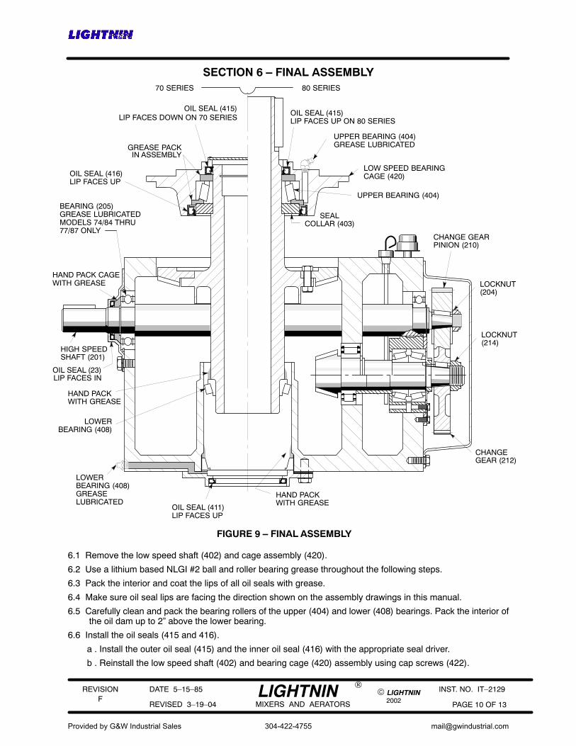
SECTION 6 – FINAL ASSEMBLY
CHANGE GEARPINION (210)
CHANGEGEAR (212)
HAND PACKWITH GREASE
OIL SEAL (23)
HIGH SPEEDSHAFT (201)
BEARING (205)GREASE LUBRICATEDMODELS 74/84 THRU77/87 ONLY
LOWERBEARING (408)GREASELUBRICATED
HAND PACK CAGEWITH GREASE
FIGURE 9 – FINAL ASSEMBLY
80 SERIES70 SERIES
UPPER BEARING (404)
GREASE PACKIN ASSEMBLY
SEALCOLLAR (403)
OIL SEAL (415)LIP FACES UP ON 80 SERIES
OIL SEAL (415)LIP FACES DOWN ON 70 SERIES
GREASE LUBRICATED
UPPER BEARING (404)
LOW SPEED BEARINGCAGE (420)OIL SEAL (416)
LIP FACES UP
OIL SEAL (411)LIP FACES UP
LOCKNUT(214)
LOCKNUT(204)
LIP FACES IN
LOWERBEARING (408)
HAND PACKWITH GREASE
6.1 Remove the low speed shaft (402) and cage assembly (420).
6.2 Use a lithium based NLGI #2 ball and roller bearing grease throughout the following steps.
6.3 Pack the interior and coat the lips of all oil seals with grease.
6.4 Make sure oil seal lips are facing the direction shown on the assembly drawings in this manual.
6.5 Carefully clean and pack the bearing rollers of the upper (404) and lower (408) bearings. Pack the interior ofthe oil dam up to 2” above the lower bearing.
6.6 Install the oil seals (415 and 416).
a . Install the outer oil seal (415) and the inner oil seal (416) with the appropriate seal driver.
b . Reinstall the low speed shaft (402) and bearing cage (420) assembly using cap screws (422).
Provided by G&W Industrial Sales
304-422-4755

REVISION
2002
DATE 5–15–85
REVISED 3–19–04 PAGE 11 OF 13
INST. NO. IT–2129F
© LIGHTNINLIGHTNINMIXERS AND AERATORS
®
c . 70 Series units only: Install gasket (28) and coverplate (27).
6.7 Change Gear Installation:
a . Double Reduction Units:
1 . Install the high speed shaft (201) and bearings (202 and 205) in the reducer housing (2).
2 . If removed, install a new oil seal (23) in the high speed seal cage (22) with the lips facing the directionindicated on the assembly drawing.
3 . Install the high speed seal cage (22) and gasket (24) using hex head cap screws (25) and lockwashers(26).
4 . Install the key (213), change gear (212) and locknut (214) on the bevel pinion shaft (101).
5 . Install the key (211), change gear pinion (210) and locknut (204) on the high speed shaft (201).
6 . Wedge a cloth or leather strap between the mesh of the pinion and gear and tighten the locknuts (204& 214) to the values shown in Table 5.
b . Triple Reduction Units:
1 . Install the intermediate shaft (315) and change gear pinion (210).
2 . Install the retainer (316).
3 . Install the key (313), high speed gear (312) and locknut (314).
4 . Install the key (213), change gear (212) and locknut (214) on the bevel pinion shaft (101).
5 . Wedge a cloth or leather strap between the mesh of the pinion and gear and tighten the locknuts (204,214 & 314) to the values shown in Table 5.
6 . If removed, install the 1/2 inch diameter dowel pin in the bottom surface of the housing (2).
7 . Model 74–84 & 75–85 only: Install the Locthred studs.
8 . Install the gasket (31).
9 . Install the high speed head (30) assembly. Align the high speed shaft as shown in Figure 3 to allow theoil slinger (306) to clear the high speed gear (312) without damage. Use care to align and not damagethe high speed pinion (310) or high speed gear (312).
10 . Install hex head cap screws (38), hex nuts (74–84 & 75–85 only) and lockwashers (39). Rotate thehigh speed pinion (310) shaft several times before tightening the hardware to the values shown inTable 4.
6.8 Install lower oil seal (411).
6.9 To insure grease channels are full, and purged of air, add grease through the fittings to the upper and lowerbearings (404 & 408) and (205, 74–84 thru 77–87). Rotate the shafts while adding grease.
a . On 70 Series units, remove the pipe plug at the top.
b . On 80 Series units, add until grease flows into the cavity above the upper oil seal (415).
6.10 Unit size 77–87: Refer to Table 1 and install oil pan if necessary.
6.11 Install change gear cover (216) and gasket (215) using hex head cap screws (217) and washers (218).
6.12 Tighten all external hardware to the recommended torques in Table 4.
6.13 Fill the unit with oil through the large opening with the socket head plug in the side of the housing to the dipstickfull mark. The approximate oil capacity is shown in the General Instructions.
6.14 Rotate the high speed shaft a few revolutions by hand to check for free running.
6.15 Re–assemble gear drive to the mixer. Install all safety guards.
6.16 Reconnect power to motor. Jog the motor and check for proper impeller shaft rotation.
Provided by G&W Industrial Sales
304-422-4755
REVISION
2002
DATE 5–15–85
REVISED 3–19–04 PAGE 12 OF 13
INST. NO. IT–2129F
© LIGHTNINLIGHTNINMIXERS AND AERATORS
®
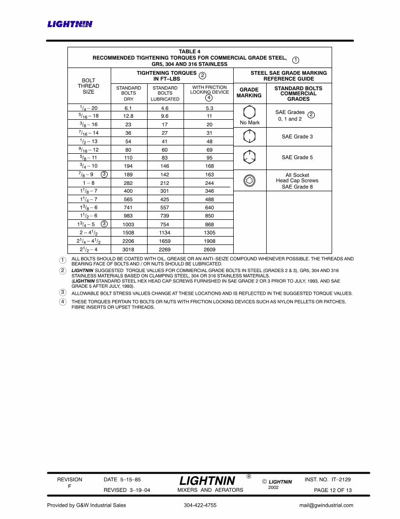
RECOMMENDED TIGHTENING TORQUES FOR COMMERCIAL GRADE STEEL, 1
BOLTTHREAD
SIZESTANDARD
BOLTSWITH FRICTION
LOCKING DEVICE4
2TIGHTENING TORQUESIN FT–LBS
STEEL SAE GRADE MARKINGREFERENCE GUIDE
GRADEMARKING
STANDARD BOLTSCOMMERCIAL
GRADES
6.1 5.3
12.8 11
23 20
36 31
54 48
80 69
110 95
194 168
189 163
282 244
400 346
565 488
741 640
983 850
1003 868
1508 1305
2206 1908
3018 2609
1/4 – 205/16 – 183/8 – 167/16 – 141/2 – 139/16 – 125/8 – 113/4 – 10
7/8 – 9
1 – 8
11/8 – 7
11/4 – 7
13/8 – 6
11/2 – 6
13/4 – 5
2 – 41/221/4 – 41/2
21/2 – 4
No Mark
SAE Grades0, 1 and 2
2
SAE Grade 3
1 ALL BOLTS SHOULD BE COATED WITH OIL, GREASE OR AN ANTI–SEIZE COMPOUND WHENEVER POSSIBLE. THE THREADS ANDBEARING FACE OF BOLTS AND / OR NUTS SHOULD BE LUBRICATED.
2 LIGHTNINSTAINLESS MATERIALS BASED ON CLAMPING STEEL, 304 OR 316 STAINLESS MATERIALS.
3 ALLOWABLE BOLT STRESS VALUES CHANGE AT THESE LOCATIONS AND IS REFLECTED IN THE SUGGESTED TORQUE VALUES.
(LIGHTNIN STANDARD STEEL HEX HEAD CAP SCREWS FURNISHED IN SAE GRADE 2 OR 3 PRIOR TO JULY, 1993, AND SAEGRADE 5 AFTER JULY, 1993).
4 THESE TORQUES PERTAIN TO BOLTS OR NUTS WITH FRICTION LOCKING DEVICES SUCH AS NYLON PELLETS OR PATCHES,FIBRE INSERTS OR UPSET THREADS.
3
3
SAE Grade 5
All SocketHead Cap Screws
SUGGESTED TORQUE VALUES FOR COMMERCIAL GRADE BOLTS IN STEEL (GRADES 2 & 3), GR5, 304 AND 316
SAE Grade 8
GR5, 304 AND 316 STAINLESS
DRY
STANDARDBOLTS
4.6
9.6
17
27
41
60
83
146
142
212
301
425
557
739
754
1134
1659
2269
LUBRICATED
TABLE 4
Provided by G&W Industrial Sales
304-422-4755
REVISION
2002
DATE 5–15–85
REVISED 3–19–04 PAGE 13 OF 13
INST. NO. IT–2129F
© LIGHTNINLIGHTNINMIXERS AND AERATORS
®
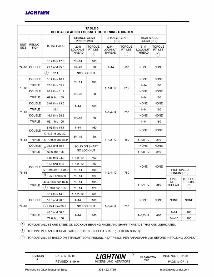
TABLE 5HELICAL GEARING LOCKNUT TIGHTENING TORQUES
UNITSIZE
REDUC–TION
DOUBLE
CHANGE GEARPINION (210)
(204)LOCKNUTTHREAD
TORQUEFT–LBS
CHANGE GEAR(212)
(214)LOCKNUTTHREAD
TORQUEFT–LBS
HIGH SPEEDGEAR (312)
(314)LOCKNUTTHREAD
TORQUEFT–LBS
1 1 1
1
TOTAL RATIO
HIGH SPEEDPINION (310)
(320)NUT
THREAD
TORQUEFT–LBS
1
72–82
5.17 thru 17.0 7/8–14 105
1–14 160 NONE NONE21.1 and 25.6 1/2–20 20
32.1 NO LOCKNUT
5.17 thru 16.77/8–14 105
NONE NONE
37.8 thru 55.91–1/8–12 210
1–14 160
20.9 thru 31.41/2–20 20
NONE NONE
69.9 thru 105 1–14 160
6.07 thru 13.61–14 160
NONE NONE
45.41–1/4–12 250
1–14 160
16.7 thru 38.25/8–18 50
NONE NONE
55.1 thru 105 1–14 160
6.03 thru 14.1 1–14 160NONE NONE
17.4, 21.5 and 32.13/4–16 60
47.7, 58.9 and 87.9 1–1/2–12 460 1–1/8–12 210
25.5 and 38.1 SOLID ON SHAFT NONE NONE
69.6 and 105 NO LOCKNUT 1–1/8–12 210
6.03 thru 9.50 1–1/2–12 460
11.5 and 14.2 1–1/2–12 300NONE NONE
17.1 thru 21.1 & 31.7 7/8–14 1051–3/4–12 750
25.3 and 37.9 7/8–14 120
47.4, 58.6 and 87.6 7/8–14 1051–1/4–12 250
70.3 and 105 7/8–14 120
6.14 thru 14.0 1–1/2–12 460
16.8 and 20.5 1–14 160 NONE NONE
25.4 thru 38.1 NO LOCKNUT 1–3/4–12 750
48.0 and 58.01–14 160 1–1/2–12 460
71.6 thru 108
DOUBLE
TRIPLE
DOUBLE
TRIPLE
DOUBLE
TRIPLE
DOUBLE
TRIPLE
DOUBLE
TRIPLE
DOUBLE
TRIPLE
DOUBLE
TRIPLE
DOUBLE
TRIPLE
73–83
74–84
75–85
76–86
77–87
NONE NONE
1–14 160
3/4–16 100
TORQUE VALUES ARE BASED ON LOCKNUT BEARING FACES AND SHAFT THREADS THAT ARE LUBRICATED.
2 THE PINION IS AN INTEGRAL PART OF THE HIGH SPEED SHAFT (SOLID ON SHAFT).
3 TORQUE VALUES BASED ON STRAIGHT BORE PINIONS. HEAT PINION PER PARAGRAPH 2.3g BEFORE INSTALLING LOCKNUT.
2
2
2
3
3
Provided by G&W Industrial Sales
304-422-4755