LIGHTENING STRUCTURES BY METAL REPLACEMENT: FROM ...
20
FACTA UNIVERSITATIS Series: Mechanical Engineering Vol. 19, N o 2, 2021, pp. 155 - 174 https://doi.org/10.22190/FUME201215043F © 2021 by University of Niš, Serbia | Creative Commons License: CC BY-NC-ND Original scientific paperLIGHTENING STRUCTURES BY METAL REPLACEMENT: FROM TRADITIONAL GYM EQUIPMENT TO AN ADVANCED FIBER-REINFORCED COMPOSITE EXOSKELETON Cristiano Fragassa Department of Industrial Engineering, Alma Mater Studiorum University of Bologna, Italy Abstract. A redesign procedure used for introducing new functional properties in innovative gym equipment is here reported. It is based on a metal replacement action where a tempered steel was firstly replaced by an aluminum alloy and then by high strength-to-weight fiber-reinforced polymers. The effect of fiber properties (as strength and volume ratio) and plies stacking sequences (as thicknesses and orientation) were investigated. Numerical analyses, done by Ansys ACP, allowed evaluating the stress- strain behavior in realistic boundaries and quasi-static loads, comparing materials and layouts in terms of stiffness. The single-layered shell method with additional integration points was preferred as a technique for discretizing composite laminates. Maximum Principal Stress and Maximum Distortion Energy (Tsai-Hill) were applied as anisotropic failure criteria. Changes in geometry were also considered given their relevant effects on parts and processes. Specifically, this paper is focused on a representative component of the main kinematic chain (the ‘forearm’) and details the different redesign phases for that part. The chosen solution consisted of 14 layers of unidirectional and bidirectional carbon fiber-reinforced pre-pregs, offering a 68 % weight reduction with respect to a solid aluminum component with equal stiffness. The part was manufactured by hand lay-up and cured in autoclave. This redesign practice was extended to the rest of the equipment allowing its transformation into an exoskeleton. Key Words: Material Design, Functional Design, Exoskeleton, Fiber Reinforced Polymers, Strength-to-weight Ratio, Exercise Machine, Rehabilitation 1. INTRODUCTION The replacement of metals by polymer-based materials has become a common practice nowadays in many engineering areas due to a series of benefits, both in terms of the components and processes they are able to provide. Received December 15, 2020 / Accepted May 28, 2021 Corresponding author: Cristiano Fragassa Department of Industrial Engineering, University of Bologna, Viale del Risorgimento 2, 40136 Italy E-mail: [email protected]
Transcript of LIGHTENING STRUCTURES BY METAL REPLACEMENT: FROM ...

FACTA UNIVERSITATIS Series: Mechanical Engineering Vol. 19, No 2, 2021, pp. 155 - 174
https://doi.org/10.22190/FUME201215043F
© 2021 by University of Niš, Serbia | Creative Commons License: CC BY-NC-ND
Original scientific paper
LIGHTENING STRUCTURES BY METAL REPLACEMENT:
FROM TRADITIONAL GYM EQUIPMENT TO AN ADVANCED
FIBER-REINFORCED COMPOSITE EXOSKELETON
Cristiano Fragassa
Department of Industrial Engineering, Alma Mater Studiorum University of Bologna, Italy
Abstract. A redesign procedure used for introducing new functional properties in
innovative gym equipment is here reported. It is based on a metal replacement action
where a tempered steel was firstly replaced by an aluminum alloy and then by high
strength-to-weight fiber-reinforced polymers. The effect of fiber properties (as strength
and volume ratio) and plies stacking sequences (as thicknesses and orientation) were
investigated. Numerical analyses, done by Ansys ACP, allowed evaluating the stress-
strain behavior in realistic boundaries and quasi-static loads, comparing materials and
layouts in terms of stiffness. The single-layered shell method with additional integration
points was preferred as a technique for discretizing composite laminates. Maximum
Principal Stress and Maximum Distortion Energy (Tsai-Hill) were applied as
anisotropic failure criteria. Changes in geometry were also considered given their
relevant effects on parts and processes. Specifically, this paper is focused on a
representative component of the main kinematic chain (the ‘forearm’) and details the
different redesign phases for that part. The chosen solution consisted of 14 layers of
unidirectional and bidirectional carbon fiber-reinforced pre-pregs, offering a 68 %
weight reduction with respect to a solid aluminum component with equal stiffness. The
part was manufactured by hand lay-up and cured in autoclave. This redesign practice
was extended to the rest of the equipment allowing its transformation into an
exoskeleton.
Key Words: Material Design, Functional Design, Exoskeleton, Fiber Reinforced
Polymers, Strength-to-weight Ratio, Exercise Machine, Rehabilitation
1. INTRODUCTION
The replacement of metals by polymer-based materials has become a common
practice nowadays in many engineering areas due to a series of benefits, both in terms of
the components and processes they are able to provide.
Received December 15, 2020 / Accepted May 28, 2021
Corresponding author: Cristiano Fragassa Department of Industrial Engineering, University of Bologna, Viale del Risorgimento 2, 40136 Italy
E-mail: [email protected]

156 C. FRAGASSA
These materials offer the possibility of conducting a thorough system optimization
based on weight reduction and performance increase based on a tailored-design premise.
Designers can also count on thermal stability, resistance to corrosion and oxidation,
thermal, acoustic, and electrical insulations through shorter manufacturing processes and
reduced material waste, thus increasing overall savings [1].
Automotive and aircraft industries were the first industrial sectors to benefit from a
progressive metal replacement. A gradual decrease of ferrous (as steel alloy, carbon steel,
cast iron and wrought iron) and non-ferrous metals (primarily aluminum) presence in the
vehicle design over the years is reported [2]. In these cases, metallic alloys are often
replaced by high performance polymers and reinforced polymer sandwiches on the way to
improving the parts performance. A representative case is stated in [3] in which reinforced
plastic replaced steel achieved 23% of weight reduction in the passenger airbag housing.
This new component also successfully passed all the strict validation tests.
However, each major industrial sector has been involved in replacing, to some extent,
metals with plastic polymers [4]. According to their lower material density, a 20/30%
weight reduction can be generically estimated in relation to their use, even more in the
presence of high strength-to-weight fiber-reinforced polymers (FRP) [4, 5].
Therefore, the material replacement has become such a common and effective design
strategy that some cases emerge in which designers have even replaced composites with
composites despite trying to (re)introduce metals. This situation is evident, for instance,
in a work concerning railway sleepers [6]. They were traditionally made by hardwood
timbers and the use of metal (carbon steel) or concrete was under evaluation. Extending
the material alternatives to composites as well, the best solution in terms of strengthening
and in-service costs reduction responded to the utilization of fiber (glass or carbon)
reinforced composites, either as a single constituent material, or as timber reinforcement
layers (e.g. applied by wrapping).
At a glance, comparing a quite common carbon fiber-reinforced polymer (CFRP) as Toray
T700, a structural aluminum alloy as 6061-T6 (Al) and a conventional tempered steel as ISO
C40, it is easy to notice the potential benefits offered by CFRP regarding the combination of
lightness and stiffness. The CFRP specific weight (2200 kg/m3) is 20% lower than the
mentioned lightweight Al alloy (2720 kg/m3) and 3.5 times lighter than SST (7800 kg/m3). At
the same time, the CFRP mechanical properties are also remarkable [7] with Young's modulus
(E) up to 112 GPa, and Ultimate Tensile Strength (UTM) up to 1100 MPa), making this
material a consistent alternative to both Al (71 GPa and 310 MPa) or SST (190 GPa, 510
MPa) in many structural applications [7].
Moreover, the variability due to anisotropy (e.g. E and UTM ranging between 35-112
and 0.25-1.1 GPa, respectively, for T700) permits optimizing part geometries based on
local stress distributions [8]. For instance, in [9] a genetic algorithm was used during the
process of design optimization (‘layout design’) of 8-layer composite laminates intended
to withstand transverse or in-plane loads. Aspects such as fiber type (i.e. glass, carbon,
and aramid), ply orientation and thickness were modified following a multi-objective
approach while Finite Elements (FEs) permitted verifying failure criteria (i.e. by means
of the Tsai–Wu theory). Depending on the specific design target, the algorithm permitted
to widely range out in terms of weight (±33%), deflection (±76%) and cost (±43%).
However, the design concept that material changes can improve product performances
is fairly known among designers. Less frequent is the case in which a metal replacement
leads to significant changes in the product functionality such as it is reported hereby.

Lightening Structures by Metal Replacement: from a Traditional Gym Equipment to an Advanced... 157
This paper proposes the case of advanced gym equipment, innovative with respect to
several functional solutions, and that is able to offer a rather exclusive gym training
method. The equipment is lightened thanks to a combination of geometric modifications
and metal replacements - from steel to aluminum and, finally, to reinforced composites –
on the way to being transformed into a wearable exoskeleton, thus incorporating new
functionalities.
Composite exoskeletons, using carbon or analogue extra-light fibers as reinforcement,
are available nowadays, although not very popular, especially pondering costs. In most
cases they are powered by external systems like electric motors, pneumatics, levers or
hydraulics allowing movements with increased strength and endurance. Applications
include but are not limited to military, airspace, advanced industry (in the presence of
heavy loads), civilian (firefighters and rescue workers) and medical applications.
The first exoskeleton was probably developed in 1972 in Serbia as a medical device
for rehabilitation of paraplegics [10]. It was active unwearable equipment, made by rather
traditional materials and design solutions. Then, a long time passed before the next
exoskeleton that rose to prominence was developed in the US in 1985 as a powered suit
of armor [11]. Since then, interest in exoskeletons has been growing year after year and
numerous studies describe their design techniques [12-15], including a special attention
to an optimal material selection. For instance, the case of a passive/active exoskeleton for
index finger rehabilitation is reported in [16]. This article, where much attention is paid to
assuring the highest precision of movements, highlights how the correct definition of
allowed trajectories (and, therefore, of kinematic joints) represents one among the most
challenging aspects in the exoskeletons design.
A study of the state-of-the-art in this field identified several exoskeletons that inspired
the present development. In particular, in [17] a wearable structure having links and
joints corresponding to a human upper body was patented. Similar design assumptions
were adopted for choosing and positioning connecting elements that enabled controlling
the system movements. Additional technical specifications, originating from [17], were
used here for the design of gym equipment, even if this prototype was conceived as a
non-wearable machine at that time.
In line with the mentioned literature review, the current study demonstrates how the
redesign procedure of a metallic structure into a fiber-reinforced composite one allowed a
significant reduction in weight. Therefore, the heavy supporting frame turned out to be
unnecessary, transforming the equipment into an exoskeleton and adding new functions.
To the best knowledge of the author, this is the first exoskeleton designed to ensure:
1) a completely free/unconstrained movement of the upper body, and 2) a constant and
'fluid' resistance, related to the speed of the movement but independent of location and
direction. In addition, this exoskeleton was also designed to be active, thanks to the
progressive replacement of the traditional frictional elements with magnetorheological
torque transmission devices, already investigated in a previous work [18].

158 C. FRAGASSA
2. GEOMETRY AND DESIGN
2.1. Equipment
A gym exercise machine typically creates an opposition load to be overcome as
1. Gravity force: the load is constant, generated by the weight of an object (as
handlebar, barbell, etc.), often driven and/or constrained by a mechanism.
2. Elastic force: the load is proportional for intensity to the displacement, generated
according to the spring principle (elastic bands, etc.).
3. Isokinetic force: the load depends on the speed, increasing along with the relative
speed induced on a mechanism (e.g. friction dumpers).
4. Pneumatic / hydraulic force: the load is generated using active mechanisms that
also define every aspect of the movements (as hydraulic or pneumatic pistons)
All these forces are generally constrained according to two main schemes:
a. free configuration, where forces are directed according to a single direction as,
e.g., the weight force always downwards; the elastic force with direction along
the anchor point; the isokinetic one according to the direction of cables and wires.
b. structured configuration, where forces are guided by means of articulated
mechanisms.
With respect to these concepts, the gym machine under investigation was fully designed to
be alternative and innovative. It can reproduce the complex kinematics and dynamics of the
upper limbs in accordance with the following postulates:
1. Ergonomics: the structure must adapt according to the person's build. The
functional elements of training must support the user's motor skills.
2. Functionality: the work paths, as well as the positions must be chosen as much as
possible by the user and not set by the machine. Setting too many constraints
penalizes the user's abilities in expressing primary and consequently healthy
skills.
3. Force: the force of opposition to the movement must exclude the effect of gravity
(weight force), the variation of intensity according to the arc of action (elastic
force) and the dependence on the speed of execution (isokinetic force). The load
distribution must be intrinsic to the instrument and be activated in a resistant
form only during its use.
The result is necessarily an anthropomorphic structure, dressed on the user (Fig. 1).
In particular, by means of a vest the athlete wears the system and interacts with it
through independent articulated segments. Thus, the functionality of the human structure
has been resumed, supporting it in its mechanical complexity.
Main elements are:
▪ base: a fixed base and frame, resting on the ground and supporting moving parts;
▪ jacket: a movable system, to be fixed with straps, used for height adjustment and
tutoring during the user’s vertical movements;
▪ trapezoids: a movable mechanism, able to replicate the shoulder movements;
▪ segments: a cinematic chain, able to replicate the upper limb movements. Each
side includes three segments, staying for arm, forearm and hand, integrated by
resistive elements. The hand also includes a handle representing the element of
interaction with the athlete and integrating the resistance management consoles.
These elements are shown in Table 1 together with a prediction of parts’ weight done in
accordance with geometry and specific weights. These values can be considered as a plausible

Lightening Structures by Metal Replacement: from a Traditional Gym Equipment to an Advanced... 159
estimate of the 'best attainable weight' that the different parts could have if made of metal. An
attention was also paid to consider the proper manufacturing processes: sheet metal working
(for steel) and tool machining (for steel or aluminum). Accessory elements (such as resistors
and joints) were also incorporated as weight.
Fig. 1 The innovative gym equipment (metal version): it allows free movements in space
offering a reaction of constant intensity
Table 1 Main parts of the gym equipment and weight estimation
Base Trapezoids Jacket Segments
Steel Aluminum Aluminum Aluminum
155 kg 21 kg 10 kg 17 kg
The first prototype was developed, assembled, and applied for functional tests.
Wherever convenient, tempered steel, very common in the case of gym machines, was
preferred with the scope to speed up construction and reduce costs. In particular, the large
basement was (simplified and) made by metal sheet. Many of the remaining parts were
made by CNC machining. An aluminum alloy was also used with the scope of lightening.
After a six-month testing period in operational environment (a gym), it was possible
to confirm the main design choices and functionalities. Nevertheless, also evident was the
opportunity to move towards further improvements.
The current work starts from this condition and, in particular, from the demand of
making the entire structure lighter and leaner. Such an opportunity goes beyond the usual
reasons and deeply affects the machine functionality.

160 C. FRAGASSA
The equipment, as mentioned, works by offering a free movement in space coupled
with a constant reaction. This objective is achieved by combining two main effects: 1)
elements always balanced and in equilibrium (with respect to any spatial configuration of
the equipment); 2) constant resistance concentrated in specific elements, placed at the
level of the joints. However, during the movements a further factor emerges: 3) the
inertial force, opposed to the motion and proportional in intensity to the speed changes.
Due to the high inertial masses involved, a general complication in using the equipment
was noted for the period of tests, especially during the initial movements.
2.2. Design changes
The redesign process followed two routes: design changes in shape and in materials.
However, the article is limited on those geometric changes strictly related to a proper
exploitation of materials (ignoring when they simply aimed at reducing volumes). In
addition, in order to simplify the description, it limits the narrative to a single component of
the kinematic chain (the 'forearm'), but reports results with respect to the entire machine.
Specifically, the design work started with a tempered steel component (the 'forearm')
and then went through its evolution in aluminum alloy and ended up with the final version
in reinforced composite.
Table 2 reports this design progress showing changes in shape and in weight. Weights
were estimated considering geometry and specific weight. Manufacturing technology are
also listed (i.e. tool machining for steel, die casting for aluminum and hand lay-up with
autoclave molding for composites). Table 3 specifies the main material properties related
to the chosen materials [19, 20]. In the case of the composite, properties and weight are
here indicative before an optimization based on the definition of proper stratifications.
Shape changes were introduced to favor the lightening, but also to meet some aspects
regarding the different manufacturing processes. Specifically, it can be noted that the
steel version (A) was made by CNC machine tool in two solid pieces. It represented the
proper solution for prototyping the first machine to be functionally tested in gym.
Table 2 Design evolution
Steel Aluminum Composite
Tool Machining Die Casting Autoclave
4.4 kg 1.0 kg 0.5 kg

Lightening Structures by Metal Replacement: from a Traditional Gym Equipment to an Advanced... 161
Table 3 Comparing different versions [19, 20]
Version A B C
Material Steel Aluminum Composite
Type C40 6061-T6 T1000
Young Modulus (E) GPa 193 71 121
Ultimate Strength (UTS) MPa 586 460 2231
Yield Strength (YS) MPa 207 250 -
Poisson Ratio - 0.31 0.33 0.27
Density kg/m3 7850 2770 1490
The aluminum version (B) was designed to make the whole machine and its parts
lighter. It was planned to be manufactured in die-casting. It was made as a 1:5 scale
model using rapid prototyping techniques, but never manufactured in true scale, because
it was overtaken by the composite version (C).
However, aluminum die-casting offered a broader range of shapes in comparison to
steel machining. It allowed the ‘forearm’ to be shaped in the way to reduce it to a single
part (instead of two). Non-essential areas in terms of function or resistance were also
removed thanks to the proper definition of shapes.
In addition, an excellent aluminum was selected, the 6061-T6, a lightweight and high-
resistant structural material that can be further strengthened through alloying and heat
treatments. Among others, its advantages are low density, high strength-to-weight ratio,
good corrosion resistance, ease of fabrication and diversity of form. This first material
change achieved a preliminary weight reduction (from 4.4 to 1.0 kg) to be decreased over
by using fiber-reinforced plastics.
Starting with this update (B), several changes in geometry were introduced as well
with the scope of considering the composite manufacturing technology. Specifically, as
said, autoclave molding was preferred: thanks to high temperatures and pressures, it
allows the production of composite parts characterized by high concentration of
reinforcing fibers. Therefore, several changes had to be introduced with respect to this
geometry, as shown in Fig. 2.
a) b) c)
Fig. 2 Shape changes in the case of composite version by eliminating the: a) undercut;
b) shim; c) lightening notches (version B, in aluminum, is shown)
The aim of the changes is to simplify mold productions and parts extraction, such as:
a. Elimination of the upper undercut. The undercut is in the form of the fins, arranged in
the top of the segment. Niches are also present, acting as containment tank for any
glue overflow during parts’ assembly.
162 C. FRAGASSA
b. Elimination of the shim positioned on the terminal. Its thickness has the purpose of
optimizing the ergonomic appearance. In fact, this area hosts the handle, the element
of interaction with the hand of the user.
c. Elimination of the lightening notches. Cut-outs are provided for lightening the part
and for driving forces in conditions of flexural-torsional loads.
All these design measures, used to reinforce the aluminum component in specific
areas, can be replaced by an appropriate layering in the case of composites.
3. MATERIALS AND METHODS
3.1. Fiber reinforced thermoplastics
Two high strength-to-weight ratio composites were used, reinforced by T800 and
T1000 carbon fibers. Manufactured by Toray Composites Materials Inc, they are among
the strongest fibers (230 GPa) available on the market. The real difference between them
is therefore mainly linked to the fact that a unidirectional (UD) weave was chosen for the
T1000 while the T800 was bidirectional (BD).
These fibers were supplied in the form of pre-impregnated fabrics (Prepreg) on
Epoxy. Epoxy produces a strong and stiff structure with good adhesion to the carbon
fibers. The fabrics, manufactured in rolls, already contain an optimized balance of epoxy
resin and carbon fiber. The low resin-to-carbon ratio accentuates the ability of the carbon
fibers on the way to minimizing weight and maximizing properties. In the specific case,
T1000 and T800 were able to guarantee the maximum optimization of the fiber content
which usually achieves 60% (after curing).
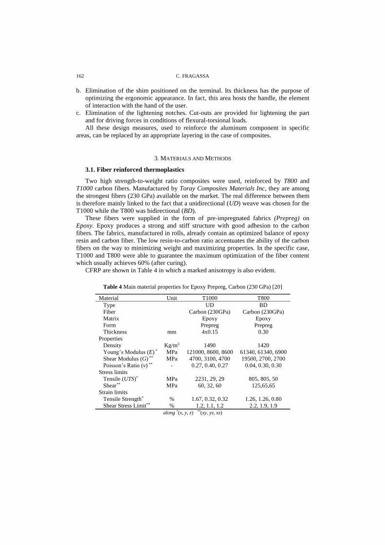
CFRP are shown in Table 4 in which a marked anisotropy is also evident.
Table 4 Main material properties for Epoxy Prepreg, Carbon (230 GPa) [20]
Material Unit T1000 T800
Type UD BD
Fiber Carbon (230GPa) Carbon (230GPa)
Matrix Epoxy Epoxy
Form Prepreg Prepreg
Thickness mm 4x0.15 0.30
Properties
Density Kg/m3 1490 1420
Young’s Modulus (E) * MPa 121000, 8600, 8600 61340, 61340, 6900
Shear Modulus (G) ** MPa 4700, 3100, 4700 19500, 2700, 2700
Poisson’s Ratio (v) ** - 0.27, 0.40, 0.27 0.04, 0.30, 0.30
Stress limits
Tensile (UTS)* MPa 2231, 29, 29 805, 805, 50
Shear** MPa 60, 32, 60 125,65,65
Strain limits
Tensile Strength* % 1.67, 0.32, 0.32 1.26, 1.26, 0.80
Shear Stress Limit** % 1.2, 1.1, 1.2 2.2, 1.9, 1.9
along *(x, y, z) **(xy, yz, xz)

Lightening Structures by Metal Replacement: from a Traditional Gym Equipment to an Advanced... 163
UD and BD prepregs were provided with 0.15 and 0.30 mm of thicknesses, respectively.
However, very thin UD fabrics were always used by overlapping 4 layers (therefore, in the
following section, a UDx4 layer means a 0.6 mm stratification of T1000, made by overlapping
4 layers of 0.15mm keeping the fibers along the same directions).
Ansys Workbench 19.3 platform was used for performing the numerical analysis. As
material models, the Ansys internal library was exploited, selecting “Epoxy Carbon UD
(230 GPa) Prepreg” and “Epoxy Carbon Woven (230 GPa) Prepreg” for T1000 and
T800 respectively where default properties were changed in accordance with Table 4.
3.2. Stacking sequences
Ansys ACP toolkit was also permitted to build exact layouts. Specifically, the composite
layout was recreated by defining the series of overlapping fabrics and their orientation, both
reciprocal and with respect to the component. ACP allows us to do this, by identifying the
specific stratification, layer by layer, orientation by orientation, with respect to each zone.
Ten different layouts (namely L1, L2, ..., L10) were defined and applied. They are
detailed in Table 5 where material and orientation are reported per each layer. In the case
of the L6-L10, a symmetrical doubling of the stratification has to be considered.
Table 5 Composite layouts
L1 L2 L3 L4 L5
1 BD 0/90 BD 0/90 BD 0/90 BD ±45 BD ±45
2 BD ±45 UDx4 ±45 UDx4 0 UDx4 0 UDx4 0
3 BD ±45 BD 0/90 BD 0/90 BD ±45 UDx4 0
4 BD 0/90 BD ±45
Layers 4 6 6 6 10
Thickness (mm) 1.2 1.2 1.2 1.8 1.2
Weight (g/m2) 1.70 1.75 1.75 1.75 2.64
L6 L7 L8 L9 L10
1 BD 0/90 BD 0/90 BD 0/90 BD 0/90 BD 0/90
2 UDx4 0 UDx4 0 UDx4 0 BD ±45 UDx4 0
3 BD 0/90 BD ±45 BD ±45 UDx4 0 BD ±45
4 symmetry BD ±45 BD 0/90 BD ±45 UDx4 0
5 symmetry symmetry BD 0/90 BD ±45
6 symmetry symmetry
Layers 12 14 14 16 22
Thickness (mm) 2.4 3.0 3.0 3.6 4.2
Weight (g/m2) 3.49 4.34 4.34 5.20 6.32
The laminates were made by overlapping up to 22 layers of UD fabrics, at an orientation
of 0° (occasionally 45° and -45°), and BD fabrics, at 0°/90° or ±45°. Between these
configurations, only the first two (L1 and L2) were quasi-isotropic (i.e. with in-plane isotropic
properties). All the others are anisotropic, better responding to the particular physical
configuration (geometry, loads, constrains) under examination.
Thickness varies from 1.2 (L1) to 4.2 mm (L10) with a specific weight slightly
changing between 1420 and 1467 kg/m3. However, layouts can be better compared using
the weight per unit area, usually expressed in g/m2: it varies between 1700 and 6320 g/m2

164 C. FRAGASSA
for a thickness of, respectively, 1.2 (L1) and 4.2 mm (L10). As reference, a 4.2 mm
aluminum foil in 6061-T6 has a weight of 11.6 kg/m2.
3.3. Loads and Constrains
The comparison was made through numerical analysis in static load configuration. The
load value was considered equal to 750N: the real value of the applied force depends on
various parameters (e.g. resistances, inertia masses), but a maximum effort of 750 N on each
of the handles was considered adequate to represent a proper load for the proposed use (i.e.
exercises in gyms).
According to the so-called human engineering, the study of people in their working
environment in order to maximize safety or efficiency, this value represents the maximum
horizontal push forces exertable intermittently and for short periods of time in the case of male
personnel [21]. Actually, this load is considered as representative when applied on the back, if
braced against a vertical wall and feet anchored on a perfectly nonslip ground. In the case of
push and pull, this load is reduced to 500 N when applied on both hands (or one shoulder) and
250 N on one hand.
The applied constraints are similar to those expected in the real kinematic chain. In
particular, there is a clear difference between version A, with a double constraint (double
fixed support), and versions B and C with a single constraint (single fixed support), as in
Fig. 3. This makes the new configurations more critical in terms of stresses and strains.
a) b) c)
Fig. 3 Loads and constrains applied to: a) steel; b) aluminum and c) composite parts
3.4. Numerical Discretization
Meshing was done using 3D ten-noded tetrahedral elements (Tet10) in the case of
steel (version A) and aluminum (version B), and 2D three-noded triangular elements
(Tri3) in the case of CFRP [22]. Finite Element (maximum) dimension was kept equal to
2.5mm. Details are available in Table 6. A control on the deformation energy of FEs is
allowed to verify the absence of critical situations in the mesh (e.g. ‘hourglass effect’).
The so-called single-layer shell method was used for discretizing the composite layout.
This simplification, quite common in the presence of geometrically complex structures,
permits us to investigate the phenomena at the level of macroscale. With a proper
conversion in properties, it reduces a multilayered laminate to an equivalent single layer
laminate with shell elements all along the surface and integration points (IP) throughout the
thickness [22, 23].

Lightening Structures by Metal Replacement: from a Traditional Gym Equipment to an Advanced... 165
Table 6 Numerical discretization by Finite Elements (FEs)
Finite Elements
Denomination TET10 TET10 TRI3
Type Solid Solid Shell
Description 10-noded tetrahedral 10-noded tetrahedral 3-noded triangle
Dimension 2.5 mm 2.5 mm 2.5 mm
Elements (tot) 678 235 217 601 166 756
Nodes (tot) 970 550 324 752 83 372
Specifically, an IP was set per each layer (i.e. without additional IP for investigating
the interfaces between layers). In such a way it was possible to limit the number of FE
speeding up the simulation focusing the attention on in-plane phenomena [22, 23].
However, this methodological limit has no practical effect on the present study.
4. RESULTS AND DISCUSSION
4.1. Aluminum vs. Steel
Fig. 4 shows the results of the simulations performed on the part, in steel (version A) and
aluminum (version B) expressed as (equivalent Von-Mises) stresses and displacements. The
values are quite different in the two cases, due to differences in: a) geometry; b) material; c)
constraint. The maximum stress reached in the components is very far from the critical
conditions of failure (UTS) or yield (YS).
In particular, maximum stress values of 58.9 and 99.7 MPa are evident for steel and
aluminum, much lower than 586 and 460 MPa as UTS (or 207 and 250 MPa as YS).
Thus, it is possible to say both these components work with safety coefficients higher
than 2.5 making convenient to prefer the aluminum solution (version B).
This version, in fact, besides being 4 times lighter, also present other advantages such as:
a) reduced overall dimensions; b) a single fixing point; c) better exploitation of material
properties with stress fields more widely distributed; d) use of a production technology
suitable to produce large numbers; e) aesthetics and ergonomics. On the other hand, the
higher displacement (3.8 vs. 1.3 mm) of aluminum does not generate dysfunctions.

166 C. FRAGASSA
a) b)
Fig. 4 Comparing steel (up) and aluminum (down) parts in terms of: a) displacements (in
mm); b) Equivalent Von Mises stress (in MPa)
4.2. Composite vs. Aluminum
As the next step, different composite layouts were modeled by numerical analysis and
compared with aluminum in terms of stiffness (Tab. 5).
The first objective was to identify an initial stratification, able to ensure a maximum
displacement for the composite part (version C) similar to the aluminum one (version B)
despite of a lower weight in the case of composite.
At this point, preliminary verified was also the presence of appropriate conditions on
the stress distribution, far from the material limit values. For this purpose, the maximum
principal stress (MPS) in the most stressed layer was compared with the T800 (BD)
tensile stress limit (UTS), equal to 805 MPa. A better check on failure criteria was
postponed to the final configuration.
In particular, 10 layouts were considered, as displayed in Fig. 5, where a progressive
reduction of displacement is evident as the laminate complexity increases. The graph also
clarifies the advantage offered by the composites with respect to metals in terms of
weight. In each case, compliance with the resistance conditions is also assured.

Lightening Structures by Metal Replacement: from a Traditional Gym Equipment to an Advanced... 167
Fig. 5 Effect of stacking sequences on mass and displacement
The L8 layout, with 14 layers (8 UD) was finally preferred (Tab. 5), able to assure the
same stiffness of aluminum (Fig. 6). Beyond the apparent complexity, this layout has
thickness of 3.0 mm and a weight of 4.34 g/cm2, permitting a 3.85 mm displacement with
a 0.32 kg of weight. It also exhibits a maximum principal stress in the most stressed layer
(2nd layer, in UD) far beyond the tensile stress limit.
UD fabrics were aligned with unidirectional fibers in the same direction, equivalent to
the longitudinal direction of the cantilever beam, which also corresponds to the prevailing
direction of the lines of forces. Besides, BD fabrics were alternated (0/90 and ±45) to
withstand non-prevailing directions of forces. Additional measures such as placing: a)
UD close to the surface, away from the neutral plane and b) BD at 0/90 as external
protective layers allowed us to improve the results.
a) b)
Fig. 6 Mechanic behavior of a fiber-reinforced composite component (Version C) in
terms of: a) displacements; b) maximum principal stress (2nd layer)

168 C. FRAGASSA
4.3. Layout Design
During the layout design, different design criteria were introduced noting that:
▪ UD fabric: a) provides high bending strength against forces aligned with the fibers
(0° orientation); b) bends with respect to forces perpendicular to the fibers (90°).
In either orientation, it exhibits low torsional strength.
▪ BD fabric: a) provides medium bending strength and medium torsional strength in
a 0° or a 90° orientation; b) is more flexible with high torsional strength at 45°.
As a practical consequence, the layout design followed these practical considerations:
▪ UD fabrics were used in the presence of and aligned with unidirectional forces.
▪ BD fabrics were used in the absence of forces along prevailing directions.
▪ BD fabrics were overlapped, when possible, considering a 45° rotation.
Moreover, composite manufacturing techniques also suggested:
▪ Layouts were symmetric to avoid differential dilations during cure.
▪ BD was used for outermost layers.
▪ Number of layers/cohesive zones between different fabrics was minimized.
▪ Proper local reinforcements were considered with respect to the most stressed areas.
Table 7 reports the effect of the different stacking sequences on the component in
terms of maximum displacement and weight. Their values permit us to better understand
the succession of layouts (L1 - L10) defined in Table 5 and the redesign process followed.
Table 7 Comparing stiffness and weight of different composite layouts
Layout L1 L2 L3 L4 L5 L6 L7 L8 L9 L10
Layers 4 6 6 6 10 12 14 14 16 22
Displacement (mm) 14.9 14.2 10.4 10.4 5.7 5.0 4.0 3.8 3.2 2.4
Part Weight (kg) 0.12 0.13 0.13 0.13 0.19 0.26 0.32 0.32 0.38 0.45
Even if the initial layouts (L1 - L5) were not adequate to assure a proper target value
of displacement (i.e. 3.8 mm), they still permitted to verify, by numerical methods, the
effect of: a) using UD instead of BD fabrics; b) fibers orientation.
Useful information emerges, in fact, when layouts were compared by means of
displacements:
▪ L1 vs. L2: displacements are equivalent (14.96 vs. 14.23) even if layouts are
different (for equivalent thickness and weight). It depends on the fact that the two
layers of used UD, placed orthogonally, are equivalent to a layer of used BD.
▪ L3 vs. L2: when the fiber orientation is not aligned with the lines of force (L2), the
displacement increases by 40%. It highlights the positive effect of a proper UD
orientation.
▪ L3 vs. L5: doubling UD layers, the displacement is reduced by a further 45%. It
confirms the relevance of a proper UD alignment as criterion for design.
▪ L3 vs. L4: an insignificant difference emerges with changing the BD orientation. It
means the BD direction can be (almost) freely defined. In this regard, it should be
noted that the BD layouts have to also consider the risk of unexpected forces.
Although none of these layouts satisfy the target, it is also evident that 8 layers of UD (L5)
allow to get quite close (5.7 vs. 3.8 mm). The next layouts (L6-10), with more layers, get the
target. They were defined also considering the opportunity of: a) not exceeding 4 overlapping
layers of the same kind; b) alternating the orientation of the BD layers.

Lightening Structures by Metal Replacement: from a Traditional Gym Equipment to an Advanced... 169
In particular:
▪ L6 represents a specular doubling of L3 layout, moving from 6 to 12 layers. The
effect is to halve the displacement (5.0 mm).
▪ L7 and L8 add two BD layers to L6, on the neutral line, reducing displacement by
further 20%. Between the two, the best is L8 which alternates directions of BDs:
with 14 layers, L8 achieves the target value for displacement (3.8 mm)
▪ L9 and L10 are layouts in which attempts are made to lower displacement (3.20
and 2.47 mm) by adding, respectively, BD or UD to L8.
4.4. Failure criteria
Every failure criterion has to consider both the material anisotropy and the specific
stacking sequence. In these terms, Fig. 7 shows the Maximum Principal Stress for the
most representative layers. In particular, Visible is the 1st layer, in BD (0/90), and the 2nd,
in UD. The additional UD layers (3rd – 5th) are not reported since their behavior largely
reflects the 2nd with lower stress values. The following BD layers, the 6th at ±45 and 7th at
0/90, are shown. The layers in the lower part are not reported since their behavior
symmetrically reflects the upper layers with lower values of stress.
a) b)
c) d)
Fig. 7 Maximum Principal Stress for the most relevant layers: a) 1st, BD 0/90; b) 2nd
UD 0; c) 6th BD ±45; d) 7th BD 0/90
Specifically, the failures were verified by the application of Maximum Principal Stress and
Maximum Distortion Energy (Tsai-Hill) failure criteria in terms of Inverse Reverse Factor
(IRF), wherever <<1. The IRF is one parameter commonly used in investigating the
composite failure. The failure load can be defined as the load value divided by IRF. Thus
when IRF>1 the composite fails and if IRF<1 it is safe. This is immediately evident in Fig. 8

170 C. FRAGASSA
where, layer by layer, a visual reference with respect to the existing gap between the
maximum principal stress and material strength (i.e. UTS) is offered.
Fig. 8 Layer-by-layer stress and material strength comparison in terms of Inverse Reverse
Factor (IRF) and Maximum Principal Stress
To avoid unnecessary bulky structure IRF is normally maintained between 0.5 and
0.75. As a result, this layout may appear oversized. This consideration is correct as long
as the present load configuration is taken into account. During the normal use, dissimilar
loads can emerge (e.g., misaligned or dynamic) moving away from an ideal condition.
In Fig. 9 failure results with respect to the Tsai-Hill criterion were also reported in
terms of Margin of Safety (equal to the inverse of IRF) and considering a load
intensification factor of 300%. Not even in this extreme case (i.e. a 3-times higher
applied load), any criticality emerges except close to the joint where UD layers
(especially the 2nd) seem ready to fail (Fig. 9b). This situation is related to the fact that in
this zone UD fibers are not always aligned with the lines of force. Thus, UD is found to
react along directions where it exhibits a very low stiffness (E = 8600 MPa) and strength
(UTS = 29 MPa).
a) b)
Fig. 9 Margin of Safety with respect to the Tsai-Hill criterion, also reporting the most
critical layers

Lightening Structures by Metal Replacement: from a Traditional Gym Equipment to an Advanced... 171
This design challenge, unknown in advance, was solved by:
▪ strengthening the whole connecting area by substituting UD with BD. Specifically,
replacing the same number of layers (i.e. 8) three benefits were locally achieved,
increasing thickness (from 3.8 to 5 mm), stiffness (from 8600 to 61340 MPa) and
strength (from 29 to 805 MPa) with marginal changes in weight (from 0.32 to
0.33 kg).
▪ inserting a bronze bushing, necessary for the part’s correct coupling with the rest
of the equipment.
4.5. Prototyping
The component (the forearm) was manufactured in two (asymmetrical) parts, by hand
lay-up of prepregs on open molds. Two aluminum molds were made by CNC machining
(Fig. 10a). Vacuum bags, with breather assemblies, were placed over the layup and
attached to the tool; then a vacuum is pulled prior to initiation of cure. This vacuum
bagging process consolidated the plies and reduced voids due to the off-gassing that
occurred as the matrix progressed through its chemical curing stages. The cure was
performed in autoclave where pressure (6 bar) and temperature (135 °C) facilitated a high
fiber volume fraction and low void content for maximum structural efficiency. Additional
details on the manufacturing are also available in [25] where a similar process was used.
Then, the parts were extracted from the molds (Fig. 10b), finished (Fig. 10c) and
glued. Special inserts, also in CFRP, allowed us to improve the connection.
a) b)
c) d)
Fig. 10 Production stages: a) molds; b) after curing; c) two sections; d) joining inserts

172 C. FRAGASSA
4.6. The exoskeleton
The design study was extended to the other parts of the upper limb. With respect to
the two additional segments, the essential elements of the analysis remain the same.
However, as far as possible, the different conditions expected by the statics of the human
body were taken into account. For example, the masses of the different body parts were
included; the effect of not orthogonal elements (i.e. arm and forearm are free to rotate
between 0 and 142 degree) were considered. This material change permitted to reduce the
segments weight from an initial 17 kg (in the case of aluminum) to the current 8.5 kg
(with composites). These segments now include arm, forearm, hand, and handle, for both
sides (right and left), and also integrate the resistive elements and the console box.
With respect to the initial design, the jacket (allowing wearing the exoskeleton) and
the trapezoids (simulating the shoulders’ movement) must be completely redesigned for
functional scopes. It is evident that many of their original parts lose functionality in the
presence of an exoskeleton. The new target weight is 18kg.
According to [21], where human strength and handling capacity are also classified, in
fact, this value is maximum individual weight that can be associated with a “portable”
item. However, the same standard, established for military use, also recognizes a weight
of 18.5 kg for trained soldiers in operational conditions and 27.7 kilograms when
marching. The expected weight reduction will certainly permit going below this higher
threshold, making the base not strictly necessary during gym workout.
A support structure, as an option, is still useful to make this new equipment also
accessible to the beginner athletes or for different applications (e.g. physiotherapy).
5. CONCLUSIONS
A redesign procedure, based on a metal replacement action, is here detailed with the scope
to transform advanced gym equipment into a wearable exoskeleton. A first prototype, was
designed, produced, and used as gym workout machine. In terms of training functionality, it
was fully validated, permitting new and more complex exercises. However, made in steel
sheets and aluminum castings, the weight of its moving parts (>48 kg), acting as inertial
masses against free athletes’ movements, made its utilization rather challenging except for
professional trainers. Furthermore, the excessive weight required a bulky support structure,
making the whole machine impractical.
The redesign involved the entire upper limb involving changes in shapes, materials,
and production processes. Regarding the materials, carbon fiber-reinforced composites
were chosen with high-strength fibers (230 GPa) used through epoxy unidirectional and
bidirectional fabrics. The effect of fiber properties (as strength and volume ratio) and
plies stacking sequences (as thicknesses and orientation) were numerically investigated
and a specific layout design was carried out taking into account the direction of forces.
External loads higher than expected were considered with an analysis limited to static
load configurations.
The narrative is limited to one element of the limb, the forearm, but then extends the
results to the entire kinematic chain. For the forearm, it was possible to estimate a weight
reduction from 4.4 kg for steel and 1.0 kg for aluminum, to the definitive 0.3 kg in the
case of reinforced composites. This result was obtained thanks to a stratification of 14
plies which, however, had a thickness of (only) 3.0 mm and a weight of 4.34 g/m2 (about half

Lightening Structures by Metal Replacement: from a Traditional Gym Equipment to an Advanced... 173
of an aluminum sheet with similar thickness). The structural resistance was verified with the
failure criteria provided for anisotropic materials (Maximum Principal Stress, Tsai-Hill)
highlighting a Margin of Safety never lower than 25-30%. This margin would allow a further
reduction in the stratification. However, the design procedure was addressed to optimize the
weight inside the condition to guarantee the same stiffness (compared to solid aluminum).
This result was achieved with a 2.85 mm of displacement for a beam of 400 mm subject to a
weight of 70 kg. Moreover, additional design steps can lead to the full exploitation of the
properties of these high performing composites. In this regard, in fact, before part
manufacturing, further design measures were introduced such as: the use of bidirectional
composites wherever no prevailing directions of forces emerged; a layout reduction where
stress levels were extraordinarily low (i.e. side surfaces); addition of reinforcement elements
and connection inserts. The part was manufactured by hand lay-up and autoclave curing,
confirming the estimated weight reduction of 68% (with respect to aluminum).
This redesign practice was extended to the rest of the entire upper limb, halving the
section weight, eliminating the need for support frame, and moving in the direction to
transform the original equipment into an active exoskeleton.
Acknowledgements: This paper was developed as part of the ‘Robotraining’ research project, an
international action co-financed by the Italian Ministry of Economic Development (MiSE) inside
the MI.S.E.-ICE-CRUI framework. The author would like to thank to all the colleagues that
supported the prototype production and, in particular, Stefano Berardo..
REFERENCES
1. Crawford, R.J., Martin, P.J., 2020, Plastics engineering, Butterworth-Heinemann. 2. Lyu, M.Y., Choi, T.G., 2015, Research trends in polymer materials for use in lightweight vehicles, International
journal of precision engineering and manufacturing, 161, pp. 213-220.
3. Han, S.R., Park, J.I., Cho, J.R, 2018, Development of plastic passenger air bag PAB housing for replacing the steel PAB housing and reducing the automobile weight, Journal of the Brazilian Society of Mechanical Sciences and
Engineering, 404, 224.
4. Kerns, J., 2016, Replacing metal with plastic, Machine Design, 88(9), pp. 34-42. 5. Rama, G., Marinkovic, D., Zehn, M., 2018, High performance 3-node shell element for linear and geometrically
nonlinear analysis of composite laminates, Composites Part B, 151, pp. 118-126.
6. Manalo, A., Aravinthan, T., Karunasena, W., Ticoalu, A., 2010, A review of alternative materials for replacing existing timber sleepers, Composite Structures, 923, pp. 603-611.
7. Bai, J., 2013, Advanced Fibre-Reinforced Polymer (FRP) Composites for Structural Applications - 1st Edition,
Woodhead Publishing. 8. Gürdal, Z., Haftka, R.T., Hajela, P., 1999, Design and optimization of laminated composite materials, John Wiley
Sons.
9. Almeida, F.S., Awruch, A.M., 2009, Design optimization of composite laminated structures using genetic algorithms and finite element analysis, Composite Structures, 883, pp. 443-454.
10. Vukobratovic, M.K., 2007, When were active exoskeletons actually born?, International Journal of Humanoid
Robotics, 403, pp. 459-486. 11. Hecht, J, 1986, Armour-suited warriors of the future, New Scientist, Iss.1527, pp. 31-32.
12. Näf, M.B., Koopman, A.S., Baltrusch, S., Rodriguez-Guerrero, C., Vanderborght, B., Lefeber, D., 2018, Passive
back support exoskeleton improves range of motion using flexible beams, Frontiers in Robotics and AI, 5, 72. 13. Zoss, A.B., Kazerooni, H., Chu, A., 2006, Biomechanical design of the Berkeley lower extremity exoskeleton
BLEEX, IEEE/ASME Transactions on mechatronics, 112, pp. 128-138.
14. Veneman, J.F., Kruidhof, R., Hekman, E.E., Ekkelenkamp, R., Van Asseldonk, E.H., Van Der Kooij, H. 2007, Design and evaluation of the LOPES exoskeleton robot for interactive gait rehabilitation, IEEE
Transactions on Neural Systems and Rehabilitation Engineering, 153, pp. 379-386.

174 C. FRAGASSA
15. Perry, J.C., Rosen, J., Burns, S., 2007, Upper-limb powered exoskeleton design, IEEE/ASME Transactions on Mechatronics, 124, pp. 408-417.
16. Wang, J., Li, J., Zhang, Y., Wang, S., 2009, Design of an exoskeleton for index finger rehabilitation,
IEEE Engineering in Medicine and Biology Society, pp. 5957-5960. 17. Perry, J., Rosen, J., 2008, EXOSKELETON. U.S. Patent Application No. 11/729, 998.
18. Fragassa, C., Berardi, L., Balsamini, G., 2016, Magnetorheological fluid devices: an advanced solution for an active
control on the wood manufacturing process, FME Transactions, 44(4), pp. 333-339. 19. DOD, U., 1994, Military Handbook: Metallic Materials and Elements for Aerospace Vehicle Structures, MIL-
HDBK-5G, 2 vols. US Department of Defense, Wright-Patterson AFB, OH, USA.
20. Toray: Type of Composite Fibers, https://www.toraycma.com/page.php?id=661. (access on 20.03.2020).
21. DoD, M.S., 2012, Design Criteria Standard: Human Engineering (MIL-STD-1472g). (Section 5.8.6),
Department of Defense, Washington.
22. Zienkiewicz, O. C., 1977, The Finite Element Method. 3. Edition, London. McGraw‐Hill Book Company (UK) Limited. XV, 787p.
23. Bogenfeld, R., Kreikemeier, J., Wille, T., 2018, Review and benchmark study on the analysis of low-velocity impact
on composite laminates, Engineering Failure Analysis, 86, pp. 72-99. 24. Rajbhandari, S.P., Scott, M.L.; Thomson, R.S., Hachenberg, D., An approach to modelling and predicting impact
damage in composite structures, In Proceedings of the ICAS Congress, Toronto, ON, Canada, 8th-13th, September
2002, pp. 8-13. 25. Fragassa, C., 2017, Marine Applications of Natural Fibre-Reinforced Composites: A Manufacturing Case Study, In:
Pellicer E. et al. (Eds.), Advances in Application of Industrial Biomaterials, Springer International Publishing,
Cham, CH, doi: 10.1007/978-3-319-62767-0_2, pp. 21-47.