warsaw pact nonnuclear threat to nato airbases in central europe
INL/MIS-12-25696Revision 1
Light Water Reactor Sustainability Program Advanced LWR Nuclear Fuel Cladding System Development: Technical Program Plan
December 2012
DOE Office of Nuclear Energy

DISCLAIMER
This information was prepared as an account of work sponsored by an agency of the U.S. Government. Neither the U.S. Government nor any agency thereof, nor any of their employees, makes any warranty, expressed or implied, or assumes any legal liability or responsibility for the accuracy, completeness, or usefulness, of any information, apparatus, product, or process disclosed, or represents that its use would not infringe privately owned rights. References herein to any specific commercial product, process, or service by trade name, trade mark, manufacturer, or otherwise, do not necessarily constitute or imply its endorsement, recommendation, or favoring by the U.S. Government or any agency thereof. The views and opinions of authors expressed herein do not necessarily state or reflect those of the U.S. Government or any agency thereof.

INL/MIS-12-25696Revision 1
Light Water Reactor Sustainability Program
Advanced LWR Nuclear Fuel Cladding System Development
Technical Program Plan
December 2012
Prepared by Shannon M. Bragg-Sitton
Idaho National Laboratory Idaho Falls, Idaho 83415
http://www.inl.gov
Prepared for the U.S. Department of Energy Office of Nuclear Energy
Under DOE Idaho Operations Office Contract DE-AC07-05ID14517
iii
EXECUTIVE SUMMARY
The Advanced Light Water Reactor (LWR) Nuclear Fuel Development Research and Development (R&D) Pathway encompasses strategic research focused on improving reactor core economics and safety margins through the development of an advanced fuel cladding system. To achieve significant operating improvements while remaining within safety boundaries, significant steps beyond incremental improvements in the current generation of nuclear fuel are required. Fundamental improvements are required in the areas of nuclear fuel composition, cladding integrity, and the fuel/cladding interaction to allow power uprates and increased fuel burn-up allowance while potentially improving safety margin through the adoption of an “accident tolerant” fuel system that would offer improved coping time under accident scenarios.
The LWR Sustainability (LWRS) Program activities must support the timeline dictated by utility life extension decisions (i.e. demonstration of a lead test rod in a commercial reactor within 10 years). In order to maintain the demanding development schedule that must accompany this aggressive timeline, the LWRS Program focuses on advanced fuel cladding systems that retain standard UO2 fuel pellets for deployment in currently operating LWR power plants. The LWRS work scope focuses on fuel system components outside of the fuel pellet, allowing for alteration of the existing zirconium-based clad system through coatings, addition of ceramic sleeves, or complete replacement (e.g. fully ceramic cladding). Significant interest has been expressed in silicon carbide (SiC) ceramic matrix composites (CMCs) for use in revolutionary cladding materials. It has been proposed that SiC CMCs have the potential to allow more efficient operation during normal reactor operating conditions, operate with higher safety margins under accident conditions and reduce the effects of severe accidents.
The LWRS Advanced Fuel Development Pathway adopts a staged approach to fuel clad development. The program will fully engage stakeholders throughout the development process to ensure that the investigated technologies are of interest to both researchers and the nuclear power industry, allowing for development of a revolutionary cladding system potentially applicable to all currently operating LWRs. A number of leading technologies will be selected based on established minimum performance criteria and scoping calculations for core safety under extreme conditions. The top-ranked concepts will undergo a rigorous series of mechanical, thermal and chemical characterization tests to better define their properties and operating potential in a relatively low-cost, nonnuclear test series. Only the top-ranked technologies that emerge from the nonnuclear test series will be recommended for test rodlet fabrication and in-pile nuclear testing under steady-state, transient and accident conditions. In this manner, cost associated with development of an advanced fuel cladding system will be minimized by performing nuclear tests on only one or two of the most promising technologies.
The LWRS Advanced Fuel Development Program will address the following strategic goals:
- Improve the scientific knowledge basis for understanding and predicting fundamental performance of advanced nuclear fuel and cladding in nuclear power plants;
- Apply the scientific knowledge basis to development of high-performance, high burn-up fuels with improved safety, cladding integrity, and nuclear fuel cycle economics.
As will be discussed, the steps taken in the advanced cladding system development will result in a detailed technology database for the investigated cladding materials, fabrication techniques and clad system designs. This database will include nonnuclear and nuclear properties that will be used as input data for advanced fuel performance modeling tools designed to better predict fuel system performance under both nominal and off-nominal, postulated accident conditions. Advanced computational models will encode experimental results to capture complex behavior of nuclear fuel pellets and cladding during reactor operation. Measured performance data will enable validation of the performance modeling tools. The detailed technology database for each clad design will later inform a commercial license application for the advanced nuclear fuel cladding system in the technology deployment phase of the program.

iv
CONTENTS
EXECUTIVE SUMMARY ......................................................................................................................... iii
FIGURES ..................................................................................................................................................... vi
TABLES .................................................................................................................................................... viii
ACRONYMS ............................................................................................................................................... ix
1. INTRODUCTION .............................................................................................................................. 1
1.1 Background ........................................................................................................................... 2
1.2 Zirconium-based Fuel Cladding ............................................................................................ 3
1.2.1 Current Lifetime Limiting Issues in Zirconium Alloys ....................................... 4 1.2.1.1 Corrosion ......................................................................................... 4 1.2.1.2 Oxidation Kinetics ........................................................................... 5 1.2.1.3 Hydrogen Pick-up ............................................................................ 6 1.2.1.4 Dimensional Stability ...................................................................... 6
1.2.2 Zirconium Alloy Failure Rates ............................................................................ 7
1.3 Research Purpose / Objectives .............................................................................................. 8
1.4 Methodology ......................................................................................................................... 9
2. Program Elements ............................................................................................................................ 10
2.1 Technology Selection .......................................................................................................... 11
2.1.1 Engage Stakeholders ......................................................................................... 11 2.1.2 Define Performance Requirements ................................................................... 12
2.1.2.1 Performance Metrics ...................................................................... 12 2.1.2.2 Licensing Requirement Matrix ...................................................... 13 2.1.2.3 Commercial Deployment Criteria .................................................. 14
2.1.3 Identify Technology Selection Criteria ............................................................. 15 2.1.4 Preliminary Safety Analysis .............................................................................. 16 2.1.5 Identify Leading Technologies .......................................................................... 16
2.1.5.1 Coatings for Standard Zirconium-Based Cladding ........................ 16 2.1.5.2 Silicon Carbide Technologies ........................................................ 17
2.2 Technology Development and Design ................................................................................ 28
2.2.1 Test Specimen Technical and Functional Requirements .................................. 28 2.2.2 Advanced Cladding Conceptual Design ........................................................... 30 2.2.3 Development Testing and Characterization ...................................................... 31
2.2.3.1 ASTM Codes and Standards .......................................................... 31 2.2.3.2 Materials Characterization Techniques ......................................... 34 2.2.3.3 Sample Fabrication ........................................................................ 40
2.2.4 Fuel Performance Modeling .............................................................................. 40

v
2.2.4.1 Overview of the Computational Modeling Platform ..................... 40 2.2.4.2 Data Input and Model Assessment ................................................ 41
2.2.5 Design Review and Analysis ............................................................................. 41 2.2.6 Phase 1 Ranked Technologies ........................................................................... 41
2.3 Technology Demonstrations ................................................................................................ 43
2.3.1 Rodlet Engineering Design ............................................................................... 43 2.3.2 Rodlet Fabrication ............................................................................................. 44
2.3.2.1 Quality Requirements .................................................................... 45 2.3.2.2 Safety Requirements ...................................................................... 46
2.3.3 Baseline Rodlet Characterization ...................................................................... 46 2.3.3.1 Hot Water Corrosion Testing ......................................................... 50 2.3.3.2 High Temperature Steam / Water Corrosion Testing .................... 52 2.3.3.3 Burst Testing .................................................................................. 53
2.3.4 Irradiation Testing ............................................................................................. 55 2.3.4.1 Definition of In-Pile Testing Requirements .................................. 56 2.3.4.2 Types of Demonstrations ............................................................... 56 2.3.4.3 Potential Test Facilities ................................................................. 58
2.3.5 Post-Irradiation Examination (PIE) Analysis .................................................... 59 2.3.1 Phase 2 Ranked Technologies ........................................................................... 61
2.4 Technology Deployment ..................................................................................................... 61
2.4.1 Generate Technology Database ......................................................................... 61 2.4.2 Develop Industry Partnerships .......................................................................... 62 2.4.3 NRC Licensing .................................................................................................. 62 2.4.4 Implement Technology ..................................................................................... 62
3. Program Schedule/Budget ................................................................................................................ 62
4. References ........................................................................................................................................ 65
5. Appendix .......................................................................................................................................... 74
Appendix A – Materials Characterization Test Techniques and Test Facilities ............................... 75
Appendix B – Potential Reactor Test Facilities ................................................................................ 80
Appendix C – Post-Irradiation Examination Capabilities at INL and ORNL .................................. 87
Appendix D – Example As-Built Data Package Worksheets and Checklists ................................. 101
vi
FIGURES
Figure 1. Oxide layer thickness versus exposure time for Zircaloy-4 alloy in a PWR. ................................ 5
Figure 2. Hydrogen pick-up fraction (HPUF) as a function of fuel assembly (FA) burn-up in Zr-2 and Zr-4 alloys [10]. ....................................................................................................................................... 6
Figure 3. Timeline reflecting improved performance in commercial fuel assemblies and breakdown of current pin failure mechanisms in the industry [18]. .......................................................................... 8
Figure 4. Planned work process for the Advanced LWR Nuclear Fuel Development Pathway. The first row of the table represents the primary elements of the work to be performed; subtasks are included under the primary elements. ............................................................................................................. 10
Figure 5. Example timeline for development and qualification of a new LWR fuel type [21]. ................. 14
Figure 6. Adaption of TRL levels to nuclear fuel systems. ........................................................................ 15
Figure 7. Clad thickness loss for candidate materials in flowing steam at 1 MPa. .................................... 24
Figure 8. Required oxide fuel pellet enrichment as a function of SiC cladding thickness. ....................... 25
Figure 9. Necessary SWU, natural uranium feed and depleted uranium stream as a function of enriched product’s U-235. The molar content of U-235 in the output mass of the product is constant. ......... 26
Figure 10. Basic process flow for work element 2.0.................................................................................. 29
Figure 11. Three dimesional reconstruction of rodlet geometry using X-ray tomography techniques. ..... 38
Figure 12. Example static capsule experiment [. ....................................................................................... 39
Figure 13. Example of characterization tests to be performed on fuel cladding system technologies; this example was designed specifically for a hybrid SiC CMC design but can be used as a template for alternate technologies. ...................................................................................................................... 47
Figure 14. 3-D drawing of the hot water corrosion flow system. .............................................................. 51
Figure 15. Influence of surface texture on heat flux of metal tubes in water. ............................................ 52
Figure 16. Sketch of high temperature steam corrosion test apparatus. ..................................................... 54
Figure 17. Halden burst-strain test of Zircaloy-4 tubes using a drop-weight apparatus, (a) 9.5% strain in an all-metal rodlet sample at 437 MPa (left) and (b) a Zircaloy-4 tube over-braided with SiCf CMC resisted strain up to the test limit of 460 MPa. ................................................................................. 55
Figure 18. Summary of post-irradiation examination techniques. ............................................................. 60
Figure 19. Left: Scanning thermal diffusivity microscope. This instrument, installed in a radiation hot cell at INL, is capable of measuring thermal transport in spent nuclear fuel. Right: Time resolved thermal wave microscope. Capable of measuring thermal transport with nanometer resolution in the depth direction and micron resolution in the lateral direction. .............................. 75
vii
Figure 20. Mechanical Properties Microscope .......................................................................................... 76
Figure 21. Instron Model 5848 MicroTester .............................................................................................. 76
Figure 22. Example non-destructive evaluation techniques. ...................................................................... 77
Figure 23. INL Carbon Characterization Laboratory. ................................................................................. 79
Figure 24. Low level radioactive material glove box with automated data acquisition. ............................. 79
Figure 25: ATR Cross Section and Significant Features ............................................................................ 81
Figure 26. Schematic of HFIR reactor core and beryllium reflector. ........................................................ 82
Figure 27. Cross section through HFIR midplane. .................................................................................... 83
Figure 28. Cross section through HFIR midplane providing additional detail. ......................................... 83
Figure 29. Arrangement of Halden Reactor Project Test Reactor .............................................................. 84
Figure 30. MITRR core map showing fuel element position designations and major core structures. ..... 85
Figure 31. TREAT Reactor schematic. ....................................................................................................... 86
Figure 32. HFEF Hot Cell .......................................................................................................................... 87
Figure 33. HFEF Hot Cell Windows and Manipulators ............................................................................ 88
Figure 34. A neutron radiograph or irradiated fuel test specimens. ........................................................... 89
Figure 35. Visual image of features on a light water reactor fuel rod. ....................................................... 91
Figure 36. Work area in the ORNL Irradiated Materials Examination and Testing (IMET) facility facing the examination cells, showing manipulator controls for the remote handling of highly irradiated materials. .......................................................................................................................... 95
Figure 37. Image of the Irradiated Fuels Examination Laboratory (IFEL) and layout of the hot cell facility. .............................................................................................................................................. 96
Figure 38. Images of the various equipment and facilities located within or in association to the Low Activation Materials Development and Analysis (LAMDA) laboratory. View from (a) outside, and (b) inside the clean room style contamination zone used for ceramic materials testing. View of the (c) thermophysical properties suite and (d) inside the contamination zone of the mechanical properties lab. Some of the instruments available for microstructural analysis of irradiated materials include (e) the Hitachi HD2000 scanning transmission electron microscope (STEM), (f) FEI Quanta 3D 200i (dual beam SEM with a high current focused ion beam [FIB]), and (f) FEI (Philips) CM200 TEM/STEM. The CM200 is located in the ShaRE user facility, and the HD2000 and dual beam are located in LAMDA. ............................... 98
viii
TABLES
Table 1. Weight percent composition of zirconium alloys used in nuclear applications [4; 14]. ................. 3
Table 2. Overview of SiC CMC Fabrication Processes: Benefits and Issues. ............................................ 18
Table 3. Methods for joining SiC-based materials [88]. ............................................................................. 22
Table 4. Heavy metal inventory as well as required Nat-U feed, DU waste, and SWU per AP-1000 17×17 fuel assembly [97]. ................................................................................................. 27
Table 5. Comparison between the cost of LWR oxide and SiC clad LWR assemblies in an AP-1000 core. .................................................................................................................................................. 27
Table 6. Standard test methods for ceramic matrix composites presently approved or being developed by ASTM International (as of April 2012). ..................................................................... 33
Table 7. Preliminary plan for ASTM standards development. .................................................................. 34
Table 8. ASTM test standards that are applicable for determining mechanical properties of small diameter tubular components of metallic materials. ......................................................................... 34
Table 9. Summary of measurement techniques for material characterization. .......................................... 36
Table 10. Traditional NDE techniques. ..................................................................................................... 36
Table 11. Example rodlet design analysis parameters (as defined in [110]). ............................................. 42
Table 12. Example characterization plan for rodlet prototypes. ................................................................ 48
Table 13. Justification for the recommended prototype characterization tests. .......................................... 49
Table 14. Estimated schedule and budget for advanced LWR nuclear fuel cladding system development. .................................................................................................................................... 63
Table 15. CCL measurement and test equipment. ...................................................................................... 78
ix
ACRONYMS
ASTM American Society for Testing and Materials
ATR Advanced Test Reactor
BWR Boiling Water Reactor
CASL Consortium for Advanced Simulation of Light Water Reactors
CFR Code of Federal Regulations
CFRCMC Ceramic Fiber-Reinforced Ceramic Matrix Composite
CMC Ceramic Matrix Composite
CVD Chemical Vapor Deposition
CVI Chemical Vapor Infiltration
DOE U.S. Department of Energy
DOE NE DOE Office of Nuclear Energy
DTA Differential Thermal Analysis
DU Depleted Uranium
EBSD Electron Backscatter Diffraction analysis
EDS Energy Dispersive X-ray Spectrometry
EPMA Electron Probe Micro Analyzer (Microprobe) or Analysis
EPRI Electric Power Research Institute
FA Fuel Assembly
FCR&D Fuel Cycle Research and Development
FGR Fission Gas Release
FTIR Fourier Transform Infrared spectroscopy
FY Fiscal Year
HCP Hexagonal Close-Packed
HFIR High Flux Isotope Reactor
HPUF Hydrogen Pick-Up Fraction
HRP Halden Reactor Project
HWCF Hot Water Corrosion Flow
INL Idaho National Laboratory
LOCA Loss of Coolant Accident
LPS Liquid Phase Sintering
LTA Lead Test Assembly
LTR Lead Test Rod
LWR Light-Water Reactor
x
MIT Massachusetts Institute of Technology
MI Melt Infiltration
MOOSE Multiphysics Object-Oriented Simulation Environment
NDE Non-Destructive Examination
NEAMS Nuclear Energy Advanced Modeling and Simulation
NITE Nano-Infiltration and Transient Eutectic-phase
NPP Nuclear Power Plant
NRC U.S. Nuclear Regulatory Commission
NQA Nuclear Quality Assurance
ORNL Oak Ridge National Laboratory
PAN Polyacrylonitrile
PCI Pellet Clad Interaction
PCS Primary Coolant System
PIE Post-Irradiation Examination
PIP Polymer Impregnation and Pyrolysis
PWR Pressurized Water Reactor
QA Quality Assurance
QAPD Quality Assurance Program Document
R&D Research and Development
RIA Reactivity Initiated Accident
SAD Selected area diffraction
SCC Stress Corrosion Cracking
SEM Scanning Electron Microscope
SiC Silicon Carbide
SIMS Secondary Ionization Mass Spectrometry
SWU Separative Work Unit
TEM Transmission Electron Microscope
TIO Technical Integration Office
TREAT Transient Reactor Experiment and Test Facility
TRL Technology Readiness Level
T&FR Technical & Functional Requirements
U.S. United States
WDS Wavelength Dispersive Spectrometry
XRD X-ray Diffraction
Zr-4 Zircaloy-4
1
Advanced LWR Nuclear Fuel Cladding System Development: Technical Program Plan
1. INTRODUCTION
The U.S. Department of Energy Office of Nuclear Energy (DOE-NE) published a Research and Development (R&D) Roadmap in 2010. The 2010 Nuclear Energy Roadmap organizes the DOE-NE activities around four main objectives that ensure that nuclear energy remains a compelling and viable energy option for the United States. The four objectives include:
1. Develop technologies and other solutions that can improve the reliability, sustain the safety, and extend the life of the current reactors.
2. Develop improvements in the affordability of new reactors to enable nuclear energy to help meet the Administration’s energy security and climate change goals.
3. Develop sustainable nuclear fuel cycles.
4. Understand and minimize the risks of nuclear proliferation and terrorism.
The Light Water Reactor Sustainability (LWRS) Program addresses Objective 1 of the R&D Roadmap. More details on the overall scope of the LWRS Program are provided in the LWRS Integrated Program Plan [1]. The LWRS Program is divided into four R&D Pathways: (1) Materials Aging and Degradation; (2) Advanced Light Water Reactor Nuclear Fuels; (3) Advanced Instrumentation, Information and Control Systems; and (4) Risk-Informed Safety Margin Characterization. The technical plan provided here outlines the necessary steps to design, test and deploy an advanced nuclear fuel cladding system under Pathway (2).
The focus of the Advanced LWR Nuclear Fuels Pathway is to improve the scientific knowledge basis for understanding and predicting fundamental performance of advanced nuclear fuel and cladding in nuclear power plants during both nominal and off-nominal conditions. This information will be applied in the design and development of high-performance, high burn-up fuels with improved safety, cladding integrity, and improved nuclear fuel cycle economics. Testing and development work conducted for advanced fuel cladding under the LWRS program will be tightly coordinated with the DOE-NE Fuel Cycle Research & Development (FCR&D) Program. Frequent communication with FCR&D program leadership will ensure that the work conducted under both programs is complimentary and that relevant knowledge is shared across the two programs.
Nuclear fuel performance is a significant driver of nuclear power plant (NPP) operational performance, safety, operating economics, and waste disposal requirements. Over the past two decades, the nuclear power industry has improved plant capacity factors with incremental improvements achieved in fuel system reliability and usable lifetime. However, these upgrades are reaching their maximum achievable impact within the constraints of the existing fuel designs, materials, licensing and enrichment limits.
Development and licensing of advanced, high-performance nuclear fuels through fundamental research could enable longer fuel operating cycles, power uprates and enhanced reactor safety under postulated accident conditions. A nuclear fuel system, including both cladding and fuel, capable of safely extending the response time after a loss of cooling accident (LOCA) would reduce the risk of serious reactor damage during such an event. More rapid licensing and commercial adoption of an advanced fuel system may be achievable by designing a fuel pin that retains the standard UO2 fuel pellet design but replaces the standard zirconium-based cladding with higher performance cladding.
2
The current performance and limitations of standard zirconium-based cladding used in operating LWRs in the United States provides a baseline performance measure for advanced fuel cladding options. To achieve significant safety and fuel economic improvements over the current generation of operating NPPs, the LWRS Fuels Pathway is focusing on developing advanced nuclear-grade ceramic materials to improve fuel cladding performance. The high strength and low chemical reactivity of advanced ceramics suggest that much higher performance nuclear fuel can be produced. These advanced materials will allow revolutionary cladding performance and enhanced fuel mechanical designs; in the future these materials could be used with alternate fuel pellet designs to provide even further improvement in nuclear power plant economics, operation, and safety. It is noted that many of the materials considered for advanced fuel cladding may also be applicable to reactor core structural materials (i.e. channel boxes in boiling water reactors (BWRs)); the data collected within the LWRS program will also inform decisions on future materials for these components.
Materials selected for development and testing must fit within the timeline necessary to support utility life extension decisions (i.e. deployable in a lead test rod within 10 years) and to fit within the LWRS program funding profile. These requirements should be recognized as significant constraints to the development of a revolutionary nuclear fuel cladding system. Either increased funding or extended development time could significantly impact the number and type of options investigated for cladding application. These limitations necessitate early down-selection of potential cladding system designs and conduct of lower cost non-nuclear characterization tests on several concepts prior to conducting nuclear testing on a reduced number of concepts. The development program includes several off-ramps for technologies that do not perform as well as desired or to allow periodic refocusing of the program during the development path.
As will be discussed, the steps taken in the advanced cladding system development will result in a detailed technology database for the investigated cladding materials, fabrication techniques and clad system designs. This database will include both non-nuclear and nuclear properties and performance data necessary to inform a commercial license application. The database will also provide input data and validation data for advanced fuel performance modeling tools designed to better predict fuel system performance under both nominal and postulated accident conditions. Advanced computational models will encode experimental results to capture complex behavior of nuclear fuel pellets and cladding during reactor operation. Modeling will range from mesoscale fuel grains up to the most accessible engineering-scale correlations that can be included in fuel bundle, core design, and reactor monitoring codes.
Key to the success of any technology development program is early and continual engagement of the technology stakeholders. The LWRS Program is identifying key stakeholders from industry (including vendors and operators), national laboratories and universities to ensure that the work conducted under the LWRS program is valuable to the eventual adopters of the technology. The Fuels Pathway is currently identifying and engaging stakeholders at the appropriate technical levels to ensure that their perspectives are captured in the initial identification of leading cladding technologies, initial down-selection of technologies based on non-nuclear characterization tests, and selection of the most promising designs for commercial demonstration.
The R&D path to advanced fuel cladding development and a rough estimate of the associated cost and schedule are discussed. This nuclear fuel system development plan will be updated periodically to incorporate new knowledge, to provide detailed test plans (test suite definition and associated test matrices) and to allow for redirection of the program if and when it is deemed necessary.
1.1 Background
Fundamental improvements in nuclear fuel and cladding composition are necessary to achieve significant safety and nuclear fuel economic improvements in the current generation of operating nuclear power plants. Baseline performance metrics must be clearly established before an advanced fuel cladding

3
system can be designed. At a minimum, advanced cladding must perform as well as currently licensed, zirconium-based cladding materials. Performance metrics will be established with regard to fuel burn-up, fuel pin lifetime, maximum operating temperature (normal and off-normal conditions), estimated clad failure mechanisms and rate, corrosion rates, ease of fabrication and installation, ease of used fuel processing, long-term dry storage requirements, manufacturing costs, etc. In order to justify the investment that will be required by industry to license and adopt an advanced fuel clad system, the technology must provide significant performance enhancements rather than incremental improvements similar to those previously achieved for zirconium alloys.
1.2 Zirconium-based Fuel Cladding
Development of nuclear propelled naval submarines in the 1950s prompted the selection and development of a cladding material having low neutron absorption cross-section, high strength and good corrosion performance in hot water [2]. Most common metal systems were quickly eliminated. Iron and nickel alloys were eliminated due to their high thermal neutron absorption cross-sections (0.17 cm-1 and 0.31 cm-1, respectively). Aluminum and its alloys were eliminated due to low strength at 300°C (90 MPa) [3]. Zirconium, with its extremely low macroscopic thermal neutron absorpotion cross-section (0.01 cm-1), good high temperature strength (900 MPa at 300°C) and decent corrosion resistance, was selected by Admiral Rickover as the cladding for nuclear submarine reactor fuels [3]. At the time of the selection there were no commercial processes for producing pure (hafnium removed) zirconium, nor was the corrosion resistance of pure zirconium sufficient for in-core performance. Naval reactors set out on an aggressive alloy development program to increase the corrosion resistance and to develop a commercial Hf removal process. A Zr-2.5% Sn alloy (Zircaloy-1) intended to improve corrosion resistance was accidentally melted in a crucible previously used for stainless steel, resulting in an alloy (Zircaloy-2) with excellent corrosion properties. A low tin variant of Zircaloy-2 (Zircaloy-3) was tested but did not show improved corrosion performance. Zircaloy-4 is a nickel free variant form of Zircaloy-2 designed to reduce hydrogen pick-up in reactor [3, 4].
Later development by the Soviets resulted in zirconium niobium alloys, which were later commercialized by Westinghouse and Areva as Zirlo™ and M5™, respectively. The composition of the primary commercial zirconium alloys used in nuclear reactors is provided in Table 1. Development of the Zr-Nb alloys has been spurred by the desire for increased corrosion resistance and improved high temperature creep properties to allow increased fuel rod burn-up [4, 5].
Table 1. Weight percent composition of zirconium alloys used in nuclear applications [4; 14].
Alloy Sn Fe Cr Ni Nb Zr
Zircaloy-2 1.3 -1.5 .15-.18 0.10 .05- .07 -- Balance
Zircaloy-4 1.3 -1.5 0.20 0.10 -- -- Balance
M5™ 0 .04 -- -- 1.0 Balance
Optimized Zirlo™ 0.67 0.10 -- -- 1.0 Balance
4
1.2.1 Current Lifetime Limiting Issues in Zirconium Alloys
Six decades of active alloy development has produced tailored alloy chemistries and processing methodologies that provide an adequate measure of corrosion behavior under pressurized or boiling water reactor (PWR or BWR) conditions while limiting irradiation growth and creep to the extent that these phenomena are now frequently inconsequential to reactor operation. These attractive properties of zirconium alloys render them well suited for use as nuclear fuel cladding and structural components in conventional LWR oxide fuel bundles.
The satisfactory performance of zirconium alloys is challenged once a shift is made from an environment associated with normal operating conditions in LWRs to reactor accident scenarios. A variety of accident sequences can result in the loss of cooling capability inside the core and loss of coolant that will eventually drive up the fuel temperature and expose the cladding to a high-temperature steam environment. Examples of such accident scenarios are a design basis loss of coolant accident (LOCA) or a beyond design basis station blackout accident.
1.2.1.1 Corrosion
Zirconium alloys in general are highly resistant to corrosion. Corrosion describes the deterioration of a material as it interacts with its environment. Corrosion, which is usually electrochemical in nature, consumes a material, hence reducing its load-carrying capability. Corrosion involves two chemical processes: oxidation, in which electrons are stripped from an atom, and reduction, which occurs when an electron is added to an atom. Although zirconium alloys are highly resistant, they are not immune to corrosion processes in the aggressive conditions that exist inside a commercial nuclear reactor [6]. The corrosion issues for zirconium alloys in BWRs and PWRs are unique due to the differences in operating conditions and alloys employed. BWRs utilize Zr-2, while PWRs previously used Zr-4 and are now transitioning to Zr-Nb cladding (Zirlo™ and M5™). Other major differences between the reactor types that affect corrosion are coolant boiling in BWRs, high concentration of hydrogen in PWR coolant, high concentration of oxygen in BWR coolant, and higher PWR operating temperature [7].
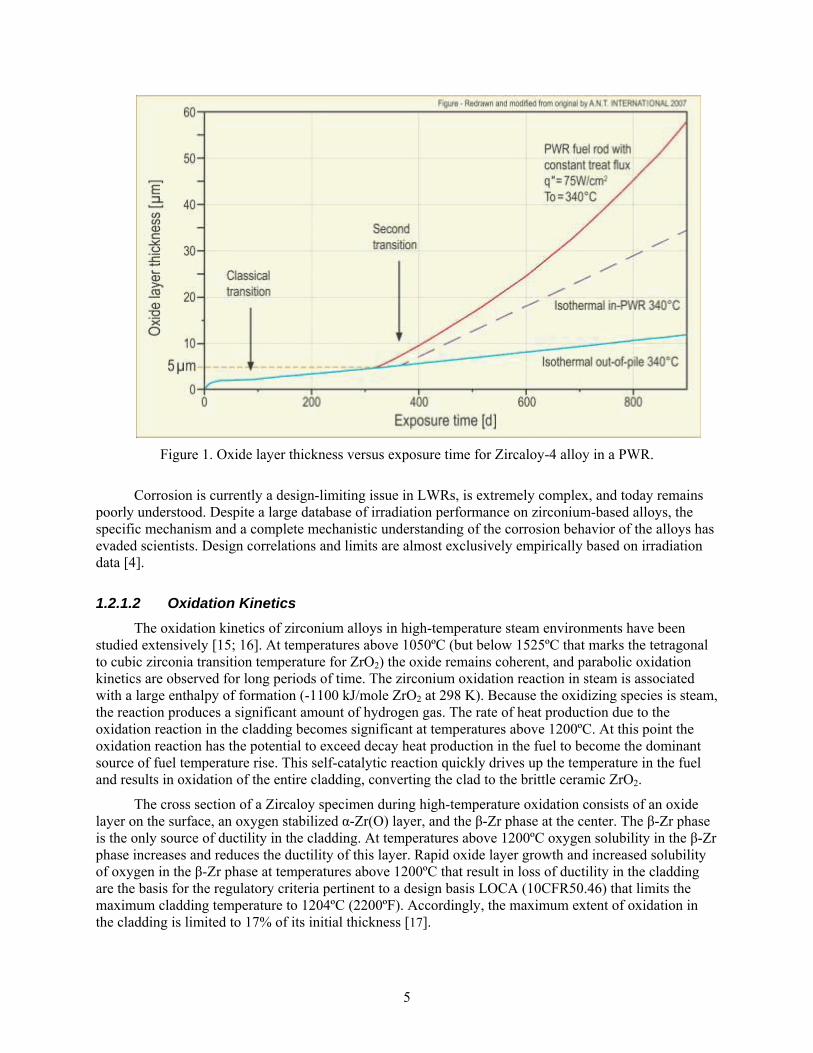
Corrosion in zirconium alloys occurs via three modes: uniform, nodular, and shadow. Both BWRs and PWRs experience uniform corrosion, while shadow and nodular corrosion are observed only in BWRs [8]. Uniform oxidation / corrosion initially follows a typical power law up to a thickness of 1.5-2 mm (typically achieved at ~30 GWd/tHM), at which point it transitions to a slower linear growth rate [4, 8]. After approximately 300 days, a second transition occurs to a faster linear rate (but still slower than power law), as shown in Figure 1. M5™ and Zirlo™ have similar corrosion behavior to Zr-4 below ~30 GWd/tHM; however, the transition to faster linear corrosion is delayed in M5™ and Zirlo™, resulting in improved corrosion performance [9].
5
Figure 1. Oxide layer thickness versus exposure time for Zircaloy-4 alloy in a PWR.
Corrosion is currently a design-limiting issue in LWRs, is extremely complex, and today remains poorly understood. Despite a large database of irradiation performance on zirconium-based alloys, the specific mechanism and a complete mechanistic understanding of the corrosion behavior of the alloys has evaded scientists. Design correlations and limits are almost exclusively empirically based on irradiation data [4].
1.2.1.2 Oxidation Kinetics
The oxidation kinetics of zirconium alloys in high-temperature steam environments have been studied extensively [15; 16]. At temperatures above 1050ºC (but below 1525ºC that marks the tetragonal to cubic zirconia transition temperature for ZrO2) the oxide remains coherent, and parabolic oxidation kinetics are observed for long periods of time. The zirconium oxidation reaction in steam is associated with a large enthalpy of formation (-1100 kJ/mole ZrO2 at 298 K). Because the oxidizing species is steam, the reaction produces a significant amount of hydrogen gas. The rate of heat production due to the oxidation reaction in the cladding becomes significant at temperatures above 1200ºC. At this point the oxidation reaction has the potential to exceed decay heat production in the fuel to become the dominant source of fuel temperature rise. This self-catalytic reaction quickly drives up the temperature in the fuel and results in oxidation of the entire cladding, converting the clad to the brittle ceramic ZrO2.
The cross section of a Zircaloy specimen during high-temperature oxidation consists of an oxide layer on the surface, an oxygen stabilized α-Zr(O) layer, and the β-Zr phase at the center. The β-Zr phase is the only source of ductility in the cladding. At temperatures above 1200ºC oxygen solubility in the β-Zr phase increases and reduces the ductility of this layer. Rapid oxide layer growth and increased solubility of oxygen in the β-Zr phase at temperatures above 1200ºC that result in loss of ductility in the cladding are the basis for the regulatory criteria pertinent to a design basis LOCA (10CFR50.46) that limits the maximum cladding temperature to 1204ºC (2200ºF). Accordingly, the maximum extent of oxidation in the cladding is limited to 17% of its initial thickness [17].
6
1.2.1.3 Hydrogen Pick-up
Hydrogen pick-up is the absorption into zirconium alloys of hydrogen generated during the corrosion process. The oxidation of zirconium by water generates free hydrogen ions which can then permeate into the zirconium metal. The solubility of hydrogen is extremely low at LWR operating temperatures (80-100 ppm); as a result, hydrogen precipitates out as hydrides [7]. These hydrides are deleterious to the corrosion properties, dimensional stability, and mechanical properties of the zirconium alloys. The hydrides precipitate and then migrate to areas of high stress, which can result in delayed hydride cracking. The presence of hydrides also causes an increased uniform corrosion rate, although the mechanism for this increase is not well understood. Additionally, due to the low density of the hydrides, hydrogen pick-up causes swelling in the zirconium alloys. Another concern with the presence of hydrides is their effect on long term stability of the cladding during long term dry storage [4, 5, 7].
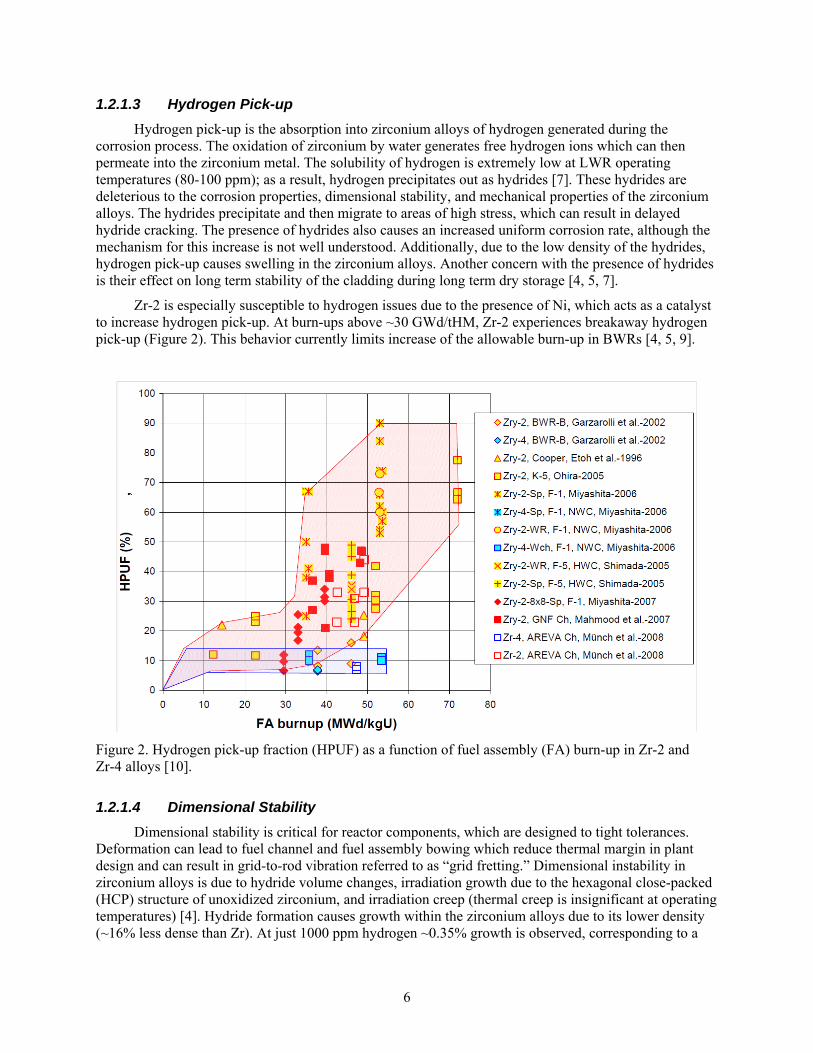
Zr-2 is especially susceptible to hydrogen issues due to the presence of Ni, which acts as a catalyst to increase hydrogen pick-up. At burn-ups above ~30 GWd/tHM, Zr-2 experiences breakaway hydrogen pick-up (Figure 2). This behavior currently limits increase of the allowable burn-up in BWRs [4, 5, 9].
Figure 2. Hydrogen pick-up fraction (HPUF) as a function of fuel assembly (FA) burn-up in Zr-2 and Zr-4 alloys [10].
1.2.1.4 Dimensional Stability
Dimensional stability is critical for reactor components, which are designed to tight tolerances. Deformation can lead to fuel channel and fuel assembly bowing which reduce thermal margin in plant design and can result in grid-to-rod vibration referred to as “grid fretting.” Dimensional instability in zirconium alloys is due to hydride volume changes, irradiation growth due to the hexagonal close-packed (HCP) structure of unoxidized zirconium, and irradiation creep (thermal creep is insignificant at operating temperatures) [4]. Hydride formation causes growth within the zirconium alloys due to its lower density (~16% less dense than Zr). At just 1000 ppm hydrogen ~0.35% growth is observed, corresponding to a
7
0.5” growth in the fuel column length [10]. Irradiation growth in zirconium is anisotropic due to the HCP structure and is strongly dependent on texture and neutron fluence. The strong correlation with fluence and the non-uniform flux profile in reactors results in non-uniform growth within long core components such as fuel rods [4, 11]. Both Zr-2 and Zr-4 alloys experience breakaway irradiation growth above ~10-15 dpa, while neither Zirlo™ nor M5™ show breakaway irradiation growth rates out to 20-25 dpa (the limit of data collected) [10].
Irradiation creep is critical to the interaction of the cladding with the fuel pellets. Initially a gap exists between the fuel pellet and cladding; the cladding then creeps down to close this gap. At higher burn-ups (>50 GWd/tHM) the gap begins to reopen due to fission gas pressure. Understanding the high burn-up creep properties of zirconium alloys is critical to knowing when the gap reopens and how large the gap will become [5, 12]. Creep is also the limiting mechanical property for many accident scenarios, such as a LOCA, due to the high temperatures seen during these accidents. Zirlo™ and M5™ have improved irradiation and thermal creep properties, allowing a larger safety margin during accident scenarios [4, 5, 12, 13].
Due to the complex interaction between irradiation growth and irradiation creep in zirconium alloys the mechanisms are poorly understood, although several mechanisms have been suggested. Empirical correlations are currently used for LWR design basis, which limits the extension of their use to design space outside of currently operating reactors [4, 7, 10, 13].
1.2.2 Zirconium Alloy Failure Rates
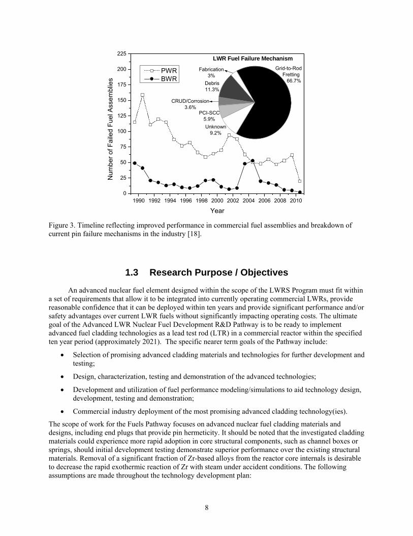
The nuclear industry has made great strides in understanding the zirconium alloy/UO2 fuel system with systematic improvement in performance as measured by failed assemblies. This is evidenced by inspection of the timeline in Figure 3, which shows the impressive improvement in performance (reduced failure of assemblies) for both PWR and BWR systems. Figure 3 also includes the current modes of pin failure, indicating grid-to-rod fretting as the major contributor [18]. Note that PCI-SCC refers to pellet-clad interaction stress corrosion cracking.
Advanced cladding system designs will assume failure criteria similar to that for standard clad fuel; specifically, failure implies loss of fission product containment from the pin. The current industry standard is approximately one failure per million fuel pins; this rate will be adopted as the maximum allowable failure in the development of advanced cladding under the LWRS Fuels Pathway. This standard assumes a fuel burn-up normal to standard zirconium alloy/UO2 on the order of 50-60 MWd/kgU. Some of the proposed advanced cladding designs could require higher enrichment nuclear fuel while also reducing or eliminating the hydrogen embrittlement and other neutron-irradiation-induced degradation issues associated with zircaloy clad (e.g. silicon carbide cladding designs). Hence, it is conceivable that substantially higher burn-ups and power uprates may be possible with advanced cladding options. Given the potential performance enhancements associated with advanced cladding it may be reasonable to assume that a higher failure rate (per pin) would be acceptable. However, any increase in the allowed failure frequency would likely be less than an order of magnitude relative to the current standard and should be the subject of future systems analyses.
8
Figure 3. Timeline reflecting improved performance in commercial fuel assemblies and breakdown of current pin failure mechanisms in the industry [18].
1.3 Research Purpose / Objectives
An advanced nuclear fuel element designed within the scope of the LWRS Program must fit within a set of requirements that allow it to be integrated into currently operating commercial LWRs, provide reasonable confidence that it can be deployed within ten years and provide significant performance and/or safety advantages over current LWR fuels without significantly impacting operating costs. The ultimate goal of the Advanced LWR Nuclear Fuel Development R&D Pathway is to be ready to implement advanced fuel cladding technologies as a lead test rod (LTR) in a commercial reactor within the specified ten year period (approximately 2021). The specific nearer term goals of the Pathway include:
Selection of promising advanced cladding materials and technologies for further development and testing;
Design, characterization, testing and demonstration of the advanced technologies;
Development and utilization of fuel performance modeling/simulations to aid technology design, development, testing and demonstration;
Commercial industry deployment of the most promising advanced cladding technology(ies).
The scope of work for the Fuels Pathway focuses on advanced nuclear fuel cladding materials and designs, including end plugs that provide pin hermeticity. It should be noted that the investigated cladding materials could experience more rapid adoption in core structural components, such as channel boxes or springs, should initial development testing demonstrate superior performance over the existing structural materials. Removal of a significant fraction of Zr-based alloys from the reactor core internals is desirable to decrease the rapid exothermic reaction of Zr with steam under accident conditions. The following assumptions are made throughout the technology development plan:
1990 1992 1994 1996 1998 2000 2002 2004 2006 2008 20100
25
50
75
100
125
150
175
200
225
Nu
mb
er
of F
aile
d F
ue
l Ass
em
blie
s
Year
PWR BWR
LWR Fuel Failure Mechanism
Fabrication3%
Debris11.3%
CRUD/Corrosion3.6%
PCI-SCC5.9%
Unknown9.2%
Grid-toGrid-to-Rod Fretting 66.7%
9
All material technologies and designs investigated must be compatible with conventional UO2 fuel pellets.
A limited number of technologies will undergo basic material development, with technology down-selection to a reduced number of options early in the program. Down-selection will be informed by nonnuclear testing and characterization and limited irradiation of sample coupons.
Funding limitations may necessitate early selection of one or two leading technologies (materials and/or designs) for further development.
Technology demonstrations may involve unfueled experiments followed by fueled experiments utilizing commercial grade UO2 (i.e. no “advanced” fuels) to examine fuel/cladding interactions.
Stakeholders will be involved throughout the advanced fuel system development activities via discussions and collaborative development activities (with possible cost sharing).
Key off-ramps are established to allow for graceful work close-out should candidate technologies be proven infeasible for eventual commercial application.
Work conducted under the LWRS Fuels Pathway will be communicated to the FCR&D leadership to ensure that the two programs are properly coordinated.
1.4 Methodology
Promising advanced nuclear fuel cladding materials and designs will be selected for further development in collaboration with key technology stakeholders, including researchers, material fabricators, industry vendors and utilities, and irradiation test facility staff. Based on significant input from the stakeholder group, the performance requirements for an advanced fuel cladding system will be established relative to the zirconium-based alloys that are currently in use in operating LWRs. Leading technologies for advanced nuclear fuel cladding will be identified based on the established performance criteria and expected economics of the candidate design. A preliminary safety analysis will also be performed to estimate the magnitude of improvement in coping time that might be achieved under accident conditions through adoption of the alternative clad system.
Figure 4 illustrates the work process that will be adopted in the development of an advanced clad system. The work process focuses on four main program elements:
1.0 Technology Selection
Identification and selection of leading cladding materials and design options (~1.5 yrs).
2.0 Technology Development and Design
Development of cladding conceptual designs, computational analysis tools and collection of preliminary test and characterization data on material coupons to inform further technology down-selection (~3 yrs).
3.0 Technology Demonstrations
Engineering design and fabrication of unfueled and fueled rodlets for baseline (nonnuclear) characterization and irradiation testing to further inform the technology database and to select leading technologies for lead test rod deployment (~3-5 yrs).
4.0 Technology Deployment
Completion of the technology database necessary for advanced nuclear fuel system licensing and qualification and deployment of one or more advanced cladding designs as a lead test
10
rod in an operating commercial reactor via industry partnerships (~1 yr + extended commercial testing).
It should be noted that although these work elements could be conducted serially, many tasks will be addressed in parallel across the work elements to ensure that facilities and measurement systems are available when they are required in the development and demonstration stages and to ensure that the 10-year development timeline can be maintained.
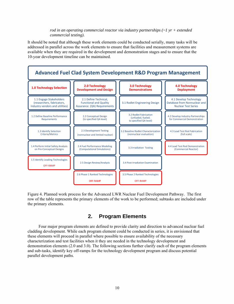
Figure 4. Planned work process for the Advanced LWR Nuclear Fuel Development Pathway. The first row of the table represents the primary elements of the work to be performed; subtasks are included under the primary elements.
2. Program Elements
Four major program elements are defined to provide clarity and direction to advanced nuclear fuel cladding development. While each program element could be conducted in series, it is envisioned that these elements will proceed in parallel where possible to ensure availability of the necessary characterization and test facilities when it they are needed in the technology development and demonstration elements (2.0 and 3.0). The following sections further clarify each of the program elements and sub-tasks, identify key off-ramps for the technology development program and discuss potential parallel development paths.
Advanced Fuel Clad System Development R&D Program Management
1.0 Technology Selection
1.1 Engage Stakeholders(researchers, fabricators,
industry vendors and utilities)
1.2 Define Baseline Performance Requirements
1.3 Identify Selection Criteria/Metrics
1.4 Perform Initial Safety Analysis on Pre‐Conceptual Designs
1.5 Identify Leading Technologies
OFF‐RAMP
2.0 TechnologyDevelopment and Design
2.1 Define Technical, Functional and Quality
Assurance (QA) Requirements
2.2 Conceptual Design(to specified QA level)
2.3 Development Testing
(nonnuclear and limited nuclear)
2.4 Fuel Performance Modeling (Computational Simulations)
2.5 Design Review/Analysis
2.6 Phase 1 Ranked Technologies
OFF‐RAMP
3.0 Technology Demonstrations
3.1 Rodlet Engineering Design
3.2 Rodlet Fabrication (unfueled, fueled;
to specified QA level)
3.2 Baseline Rodlet Characterization (nonnuclear evaluation)
3.3 Irradiation Testing
3.4 Post‐Irradiation Examination
3.5 Phase 2 Ranked Technologies
OFF‐RAMP
4.0 Technology Deployment
4.1 Develop Technology Database from Nonnuclear and
Nuclear Test Series
4.2 Develop Industry Partnerships for Commercial Demonstration
4.3 Lead Test Rod Fabrication(full scale)
4.4 Lead Test Rod Demonstration (Commercial Reactor)
11
2.1 Technology Selection
The Technology Selection work element (1.0) will provide initial technology assessment for advanced cladding materials and designs and will result in a trade study comparison of various cladding options that would be compatible with conventional UO2 fuel pellets. The trade study will account for current technology development status; technology gaps and possible pathways to address those gaps; anticipated material performance, including nuclear, mechanical, thermal and chemical behavior, based on existing literature; fabrication options; and economics. It is anticipated that this work element, which will consider multiple technologies in parallel, will take approximately six months to complete the initial trade study and an additional 12 months to conduct preliminary safety analyses (~1.5 years total).
2.1.1 Engage Stakeholders
Stakeholder support and participation is critical to the success of any advanced technology development program. A broad variety of stakeholders will be engaged early in the LWRS program to ensure that the ultimate adopters of the technology have a strong voice in selecting the technology or technologies that will undergo further development. Stakeholders include:
o Nuclear power utilities
o National Laboratory researchers
o University researchers/collaborators
o Vendors (i.e. material suppliers)
o Manufacturing / fabrication companies
o Test reactor facilities
o Department of Energy (DOE)
o Nuclear Regulatory Commission (NRC)
o Electric Power Research Institute (EPRI)
The LWRS Fuels Pathway will take advantage of the broader LWRS program strategy to identify and engage technology stakeholders at the correct technical and leadership levels, using a tiered engagement approach. The LWRS Program Technical Integration Office (TIO) engages stakeholders from a top-down approach, while the individual research Pathways are active in bottom-up engagement. This engagement strategy is being evaluated at the program level to ensure that mid-level researchers and leadership are not missed in this approach. The Fuels Pathway seeks input from stakeholders in the following areas:
o Limitations in conventional cladding technologies
o Industry interests in advanced fuel cladding (desired attributes and expectations)
o Preliminary technology database to define what data are already available for candidate technologies and what technology gaps may exist
o Performance metrics for advanced fuel cladding (including economics)
o NRC and industry requirements
o Manufacturing capabilities
o Vendor capabilities
12
o Materials (feedstock) availability and cost
o Identification of anticipated development challenges for candidate technologies
2.1.2 Define Performance Requirements
A detailed list of performance requirements and metrics must be established for all advanced fuel systems proposed. An advanced fuel / cladding system must, at a minimum, perform at least as well as the existing zirconium-based clad UO2 systems in service today, having minimal impact on safety, economics and reactor operations. To be commercially viable, advanced cladding must perform well beyond the existing state-of-the-art in one or more areas to warrant vendor and utility investment in licensing and implementing advanced fuel cladding systems. Measured performance criteria would likely include capability for power uprates and increased fuel burn-up without impacting the industry standard pin failure rate to provide the necessary economic incentive to the commercial nuclear industry (although a slight increase in pin failure rate may be an acceptable trade given significant performance enhancements). All advanced fuel cladding designs investigated under the LWRS Program will also consider the ultimate NRC licensing requirements. Although it is envisioned that the ultimate user of the advanced technology would be responsible for gaining license approval, it is the role of the LWRS Program to demonstrate overall technology performance and to collect the data required to inform a future NRC license application in collaboration with members of the nuclear industry.
2.1.2.1 Performance Metrics
Performance metrics for advanced cladding systems must align with the overall LWRS programmatic assumptions, stakeholder interests and NRC requirements. Some of these metrics may be stated qualitatively, with quantitative metrics established with stakeholder input under performance of work element 1.2. Qualitatively defined metrics include:
Compatible with existing LWR thermal hydraulics and UO2 fuel, including ease of installation and removal
Reactor compliance, including dimensional stability and predictable mechanical properties Ease of processing used fuel and used fuel storage Accordance with the LWRS Program Quality Assurance Program Description Document
(QAPD) [19] Ability to provide improved nuclear fuel economics Enhanced performance under accident conditions (relative to zirconium-based cladding)
Cladding design and measured performance of the fuel clad system under both nominal and off-nominal (accident) conditions must take into account several key issues, including:
Environmental effects o Water corrosion o Erosion/fretting o LOCA (small break and large break)
Irradiation effects Fuel/clad interactions Hermeticity
The current industry standard failure criterion is approximately one failure per million fuel pins. This criterion will also be adopted for advanced cladding options. This, however, assumes a nominal fuel burn-up in accordance with that of standard zirconium alloy/UO2 systems (~50-60 MWd/kgU). Higher burn-ups and power uprates may be possible with advanced cladding as a result of increased fuel pellet
13
enrichment (which may be necessary with modification of the cladding material within the same outer diameter of a standard fuel pin) and reduced hydrogen embrittlement and other neutron-irradiation-induced degradation issues. Taking into account performance enhancements that would result from advanced cladding, it may be reasonable to increase the allowable pin failure frequency, thereby improving nuclear fuel economics without impacting reactor safety. These considerations must be taken into account as the desired performance metrics are more clearly defined and in the evaluation of advanced cladding options as measured data become available from the suite of nonnuclear and nuclear characterization tests.
2.1.2.2 Licensing Requirement Matrix
The evaluation of fuel performance expectations needs to be measured against the NRC licensing basis requirements and potential for benefits to the entire core and reactor system. The goal is to create the basic data required for a licensing submittal and industrial confidence in the new technology and its application to existing nuclear power plants.
The fuel qualification process traditionally involves a combination of fuel design, fabrication process definition and fuel performance qualification, using in-reactor testing and performance analysis. In a recent publication, Crawford et al. [20] described the various stages of the qualification process. At that time the emphasis was placed on in-reactor testing, as this has been the traditional process. Significant advances have taken place in computational modeling in recent years, prompting the nuclear fuel development community to begin investigating what steps could potentially be replaced with modeling and analysis, using in-reactor testing to validate the results, to reduce the time and cost associated with developing a new fuel type or a new fuel clad system.
Regardless of the exact process taken, the goal of a fuel development program is to proceed from the invention stage to a fuel pin design. As such, the qualification process should:
“Demonstrate that a fuel product fabricated in accordance with a specification behaves as assumed or described in the applicable licensing safety case, and with the reliability necessary for economic operation of the reactor plant.” [21]
The qualification process requires the development of several interrelated items, including:
Choice of reactor type(s) that will use the product; from these:
Develop technical and functional requirements (T&FR) and a fuel specification; this may then require adding quality assurance (QA) steps to the fabrication process. The T&FR and specification can be rough and should be broad enough so as to require as few changes as possible in the future. Changes to these requirements may affect the subsequent processes in qualification and require back-stepping to correct.
Description of the fabrication process that will produce a uniform product. Conceptual design of engineering-scale and full-scale fabrication processes to allow assessment of efficiency loss (for example, batch yield or uranium losses), capital cost, and production cost.
Prepare a performance/safety case. The initial performance/safety case will serve as a gap analysis to uncover which fuel performance issues require further analysis/modeling and/or testing. The initial draft may also reveal where design changes are required.

14
MacDonald’s work [21] showed a timeline for ‘qualification’ of a new LWR fuel type designed for higher burn-up use; this timeline is reproduced in Figure 5. The initial draft of a safety case can be produced during the first year of development. Analysis results and requirements set by reactor operation feed back into the design and dictate changes essential for a successful design. Analysis may also show where overdesign has led to extra costs or inefficiencies. The analysis and modeling results feed back to the design, such that a final design can be fabricated and tested where required. The timeline below would then represent a fairly accurate estimate of the final steps to qualification.
The description of general fuel qualification shows a timeline that indicates ~23 years from initial design to completion of the qualification process. The first nine years, however, are consumed with building and testing prototypes. The fuel system design down-selection does not occur until year nine. It may be possible to replace these initial nine years with a much shorter period of analysis and design refinement, with some benchmark experimentation, still resulting in a final lead test rod design. In-reactor testing should be designed to address issues that cannot be satisfactorily analyzed or modeled, or to validate the results of modeling. The LWRS Fuels Pathway aims to reduce the development timeline by focusing only on advanced cladding options that are compatible with standard UO2 fuel pellets.
Figure 5. Example timeline for development and qualification of a new LWR fuel type [21].
2.1.2.3 Commercial Deployment Criteria
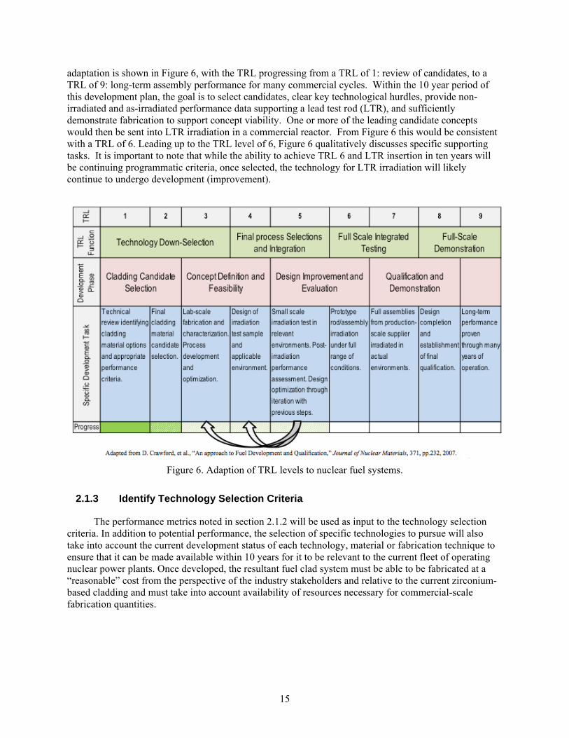
The objective of this technology development plan is to field an appropriately qualified candidate advanced cladding technology within a commercial fission power reactor within ten years. Most of the currently considered advanced cladding technologies focus on SiC materials. The ability or inability to mature the technology will be a determinant and motivation behind program R&D direction. In order to qualitatively understand the level of technological maturity required the program intends to adopt a Technology Readiness Level (TRL) approach, as modified for fuels by Crawford, et al. [20]. This
15
adaptation is shown in Figure 6, with the TRL progressing from a TRL of 1: review of candidates, to a TRL of 9: long-term assembly performance for many commercial cycles. Within the 10 year period of this development plan, the goal is to select candidates, clear key technological hurdles, provide non-irradiated and as-irradiated performance data supporting a lead test rod (LTR), and sufficiently demonstrate fabrication to support concept viability. One or more of the leading candidate concepts would then be sent into LTR irradiation in a commercial reactor. From Figure 6 this would be consistent with a TRL of 6. Leading up to the TRL level of 6, Figure 6 qualitatively discusses specific supporting tasks. It is important to note that while the ability to achieve TRL 6 and LTR insertion in ten years will be continuing programmatic criteria, once selected, the technology for LTR irradiation will likely continue to undergo development (improvement).
Figure 6. Adaption of TRL levels to nuclear fuel systems.
2.1.3 Identify Technology Selection Criteria
The performance metrics noted in section 2.1.2 will be used as input to the technology selection criteria. In addition to potential performance, the selection of specific technologies to pursue will also take into account the current development status of each technology, material or fabrication technique to ensure that it can be made available within 10 years for it to be relevant to the current fleet of operating nuclear power plants. Once developed, the resultant fuel clad system must be able to be fabricated at a “reasonable” cost from the perspective of the industry stakeholders and relative to the current zirconium-based cladding and must take into account availability of resources necessary for commercial-scale fabrication quantities.
16
2.1.4 Preliminary Safety Analysis
Preliminary safety analyses will be performed for potential fuel clad system technologies identified in the “Technology Selection” work element. These safety analyses will be of rough order, as they will be performed in parallel with conceptual design of the concepts for the advanced cladding systems. Regardless of potentially large error bars, however, these analyses will provide a baseline assessment of potential clad performance under both normal and extreme off-normal conditions. Technologies that do not provide sufficient promise for enhanced safety will not proceed through the Technology Development and Design stage. Safety analyses will be performed in collaboration with and using tools developed within the LWRS Risk-Informed Safety Margin Characterization Pathway. Necessary input requirements for these analyses will be defined in the first six months of the Technology Selection work element.
2.1.5 Identify Leading Technologies
Leading technologies that will be further developed under the LWRS Program will be selected by a technology selection committee that includes members of each stakeholder group identified under 2.1.1. Technologies will be ranked based on adherence to the criteria discussed in sections 2.1.2 and 2.1.3, anticipated safety performance indicated by the preliminary safety analyses discussed in section 2.1.4 (when these results become available), technology development status, and development risk versus potential benefit. In some cases the technology may be associated with high development risk due to current technology gaps or challenges, but they may provide the potential for significant improvement in one or more areas relative to the other technologies considered. Some of the candidate technologies currently being considered are discussed below.
2.1.5.1 Coatings for Standard Zirconium-Based Cladding
Near-term options for advanced fuel performance may include coatings on the current zirconium-based cladding to reduce water corrosion, hydrogen production, and fretting wear. These options could potentially offer incremental improvement to the fuel system performance at lower cost and reduced development time versus complete redesign of the fuel clad or fuel clad system.
The Status Report and Concept Screening Results from the Industry Advisory Committee (IAC) to the Idaho National Laboratory Advanced Light Water Reactor Fuel Development Program (issued December 2011) identified coatings on zirconium alloy cladding as a recommended topic for future research. The IAC specifically assessed the potential performance benefits of MAX phase compounds (e.g. Ti3AlC2) that could be applied as a coating on a standard cladding tube to enhance corrosion resistance and drastically reduce hydrogen production in accident scenarios. Coatings could be on the order of 10 to 20 microns thick and would be applied by thermal and cold spray techniques, although this process would require optimization. Additional research is required to characterize the survivability of a thin film coating in a severe accident. A candidate coating would also need to be demonstrated under reactor operating conditions to verify that it will not spall off and to assess the potential effects of cracking or crazing of the coating on the underlying zirconium-based cladding.
Coatings on standard zirconium alloy cladding would not significantly alter the current state-of-the-art LWR cladding designs, such that a demonstration of the technology could be readied in the near term. Although power uprates and increased fuel burn-up are not likely to be achieved via coatings since the base material would have the same limits as current cladding, coatings do have the potential to mitigate severe accident consequences increasing the reactor coping time by decreasing the clad oxidation rate and preventing direct steam contact with zirconium, thereby decreasing the total hydrogen generation and generation rate. The development path in this document focuses on ceramic cladding options (i.e. SiC-based cladding); a similar path could be adopted for coated metal cladding, with modification to the characterization test suite as necessary. Coated zirconium alloys should be considered as a potential
17
back-up technology that could be developed in a shorter time frame than ceramic cladding should the investigated ceramic cladding options fail to demonstrate the desired performance enhancements in the tests conducted under work elements 2.0 and 3.0, making use of one of the “off-ramps” included at the end of each work element. Coatings are currently being investigated under the FCRD Advanced Fuels Campaign accident tolerant fuels research.
2.1.5.2 Silicon Carbide Technologies
Recent investigations of potential options for “accident tolerant” nuclear fuel systems point to the potential benefits of silicon carbide (SiC) cladding relative to zirconium-based alloys, including increased corrosion resistance, reduced oxidation and heat of oxidation, and reduced hydrogen generation under steam attack (off-normal conditions). SiC is available in both alpha and beta phase and in various forms, including monolithic, fiber, ceramic matrix composites, etc. Each form and fabrication technique results in varied mechanical strength, thermal properties, chemical properties, and radiation resistance. The discussion below offers insight to some of the SiC fabrication techniques that may be considered in the LWR advanced fuel development, along with estimation of their current technology development status, benefits and outstanding issues.
The two primary design concepts utilizing SiC composites considered for LWR cladding include fully ceramic SiC/SiC cladding and ceramic / metal “hybrid” cladding. Both the all SiC fiber (SiCf) ceramic matrix composite (CMC) cladding and SiC fiber CMC metal hybrid cladding (SiC CMC over an inner metallic liner tube) will be considered in this development program. Various technical, operational, economic, materials interaction and fabrication issues must be addressed for each design category. Hermeticity is a key functional requirement for any cladding design. A critical need for any technology involving silicon carbide composites is development of a reliable joining methodology that can withstand the radiation environment inherent to nuclear applications. Candidate joining technologies currently under investigation will be addressed in the ensuing discussion.
2.1.5.2.1 SiC Fabrication Processes
The process of forming a thin-walled CMC tube uses textile methods of continuous fiber braid lay-up (preforming) or filament winding over a mandrel followed by formation of a very thin (sub micron) interface debond layer between the fibers and adjacent ceramic matrix followed by the process to form the SiC ceramic matrix. The interface debond layer between the fiber and the matrix is deposited for the purpose of transferring mechanical load within and through the ceramic fiber reinforced CMC (CFRCMC). This debond layer can consist of a number of materials such as pyrolytic (PyC), oxide ceramics, or boron nitride (BN). PyC has known radiation stability issues that lead to cracking, such that it may not be appropriate for fabrication of SiC components intended for reactor applications.
There are multiple industrial processes for forming the SiC ceramic matrix surrounding the continuous ceramic fibers. The most common processes include:
Chemical Vapor Infiltration (CVI) of the SiC (using isothermal or temperature-gradient and forced-flow, isobaric or pulsed flow methods),
Pre-ceramic liquid Polymer Impregnation and Pyrolysis (PIP) formation followed by elevated temperature conversion to SiC,
Direct reaction-formed SiC matrix using melt-infiltration (MI) methods,
Nano-Infiltration and Transient Eutectic-phase (NITE) formation of the SiC matrix using the transient liquid phase-assisted pressure sintering process.

18
The known benefits and challenges associated with each of these methods are provided in Table 2. An excellent review of these processing methods has been published by Naslain [22].
Table 2. Overview of SiC CMC Fabrication Processes: Benefits and Issues.
Matrix process Measured performance / Demonstrated benefits
Issues that need to be addressed*
CVI
- Irradiation stability
- Corrosion resistance
- Baseline properties
- Fabrication scalability
PIP - Fabrication scalability
- Baseline properties
- Irradiation stability
- Corrosion resistance
MI - Baseline properties
- Irradiation stability
- Corrosion resistance
- Fabrication scalability
NITE - Irradiation stability
- Baseline properties
- Corrosion resistance
- Fabrication scalability
*Process economics should be addressed for all matrix forming technologies.
Chemical Vapor Infiltration (CVI) is a variant on chemical vapor deposition (CVD). CVD implies deposition onto a surface, whereas CVI implies deposition within a body. The CVI process is used as a means of fabricating ceramic matrix composites such as SiCf/SiC (silicon carbide fiber reinforced silicon carbide) [23, 24]. The CVI process uses reactant gases that need to diffuse into an isothermal or temperature-graded porous fiber preform and form a deposition. The deposited SiC material is a result of chemical reactions occurring at or on the fiber surfaces. The infiltration of the gaseous precursor into the preform is driven by either diffusion processes or an imposed external gas pressure. The infiltration proceeds as the silicon carbide (matrix) deposition fills the space between the fibers, forming composite material in which the SiC matrix is the deposited material and the fibers of the preform make up the dispersed phase. The SiC matrix often is formed from a mixture of methyltrichlorosilane (MTS) as the precursor and hydrogen as the carrier gas for the MTS. CVI densifies SiC matrix composites at relatively low temperatures, typically around 1100°C. To make the completed CMC composite, an interface layer (such as carbon) is also needed between the SiC fiber and the SiC matrix. This layer is made using a hydrocarbon precursor (such as CH4). The matrix densification stops when the preform surface pores are closed. The final residual closed porosity of the ceramic composites fabricated by the CVI method may reach 10-15% for a typical two-dimensional fabric lay-up architecture. By light machining of the surface additional vapor penetration into the fibers can be effected into the matrix. A common variant of CVI is isothermal-isobaric CVI (I-CVI). There are several additional, less common variants of CVI depending on how the preform temperature is designed (isothermal, temperature-graded, or locally heated) and how the reactant gas flow is controlled (isobaric, forced flow, or pulsed flow). The alternative CVI configurations often require substantially more complex process design and are employed to expedite the densification process, reduce porosity in the final product, or enable selective area deposition.
CVI is a “batch” process known to require capital intensive and complex reactors, costly reactant gases, and control of potential flammable off-gases. Process run times can range from days to weeks,
19
yielding a low final part throughput. Any stoppage of the CVI process can result in an internal Si or C rich layer over the deposited SiC layer. The presence of this layer needs to be assessed for quality and performance reasons, as either free Si or C would result in poor performance within a radiation environment.
The CVI process relies on SiC formation from specific gas phase reactants which can be adjusted during SiC matrix formation to yield layers of SiC containing silicon or carbon rich layers. In general, for nuclear applications where the CFRCMC will be exposed to neutron radiation, a stoichiometric composition (Si/C = 1) is preferred, as excess Si or C can lead to local swelling under neutron irradiation [84]. If the CVI process is stopped for any reason during the formation of the SiC matrix an excess Si or C layer is deposited on the prime SiC as the process gas chemistry exhibits abrupt changes in local temperature and chemistry which leads to layers of deposited SiC with ratios less than or greater than 1. For many non-nuclear applications local variations in the Si/C ratio is not an issue. However, excess Si is known to swell under irradiation [39] and may cause swelling in SiC materials. Detection of excess Si in the matrix should be included as part of the in-process QA. In most industrial CVI processes for SiC matrix formation, adjustments to the MTS reactant gas is currently used to avoid the formation of metallic silicon as the second phase.
Polymer Impregnation and Pyrolysis (PIP) uses liquid polymers that convert to form the desired ceramic matrix for CFRCMC [25 - 28]. Current PIP techniques can be used to form ceramic matrices consisting of carbon, silicon carbide (SiC), silicon oxycarbide (SiOC), silicon nitride (Si3N4) and silicon oxynitride (Si3ON3). PIP involves the following operations [29]:
The continuous fiber preform (or powder compact) is immersed into then saturated with a low viscosity pre-ceramic polymeric precursor polymer. Several of the polymers used to make the SiC matrix are liquid at room temperature, allowing immersion under light vacuum to saturate the fiber preform.
The polymer is cured or cross-linked at about 250 ºC (480 ºF).
The polymer precursor is then pyrolyzed at 800-1300°C (1472-2372°F). As a result of pyrolysis the polymer converts to the desired ceramic, such as SiC, SiOC, Si3N4 and Si3ON3. Pyrolysis causes shrinkage of the matrix material and formation of pores (typical yield upon ceramization is up to 40 volume %).
The pyrolyzed polymeric precursor may be hot pressed for additional densification if desired. A hot pressing step is normally not done with CFRCMC as damage to the fibers may result.
The impregnation – pyrolysis cycle is repeated several times until the desired density is achieved.
The following materials are used as polymers in the PIP process:
Thermosets (thermosetting resins);
Pitches or other carbon-containing liquids for fabrication of the carbon matrix;
Polycarbosilane, polysilastyrol, dodecamethylcyclohexasilane for fabrication of silicon carbide matrix.
PIP is a simple, low temperature method that can potentially allow low cost production of simple and complex parts including CFRCMCs [30, 31]. PIP is performed at room temperature and with conventional industrial processing equipment, including simple high vacuum and radiant heating furnaces. With the exception of the pre-ceramic polymers used, the PIP process is applicable to large L/D tubular products with scale-up to 10 feet and longer.
Use of pre-ceramic polymers that convert to silicon carbide upon heating is a simple process to control the stoichiometric formation and crystalline structure of SiC [132,133]. Several polymers have
20
been developed by industry, including StarFire™ and Ceraset™ [29], with each polymer having a different chemical backbone designed to yield Si/C ratios of 1.0 ± 0.1 when heated under proper temperature and atmospheric conditions (i.e. argon). In addition, these polymers can be made with very low residual impurities (ppm or less) to minimize the presence of long-lived activation products. At present the SiC yield of these polymers is typically 70 – 80%. Thin CFRCMC materials, on the order of 2 to 10 layers of SiC fiber fabric, require from 3 to 7 impregnation cycles to complete the SiC matrix formation.
Conventional PIP SiC matrix had been demonstrated to be unstable in a radiation environment. The primary reason for the radiation instability is the nano-crystalline siliconoxicarbide structure that progressively crystalizes during irradiation at temperatures above the amorphization-threshold temperature for SiC (~150°C), accompanying substantial volumetric contraction and embrittlement due to extensive intergranular micro-cracking. An example of irradiation-induced shrinkage of the amorphous/nano-crystalline PIP SiC matrix is reported in [32]. Reports on the effect of neutron irradiation on the PIP SiC/SiC composites have been rare because the samples are often unsuitable for examination after irradiation. However, neutron irradiation effects on the polycarbosilane-derived ceramic grade Nicalon™ fiber, which is of the microstructure analogous to the polycarbosilane-derived SiC matrix, has been published reporting substantial diametral contraction [33].
Improving the irradiation stability of PIP SiC matrix composite is considered possible by minimizing the amount of polymer-derived SiC in the matrix by loading the polymer precursor with filler particulates, and/or transforming the PIP matrix into a fully crystallized and stoichiometric form of SiC through a heat treatment at temperatures exceeding the conventional pyrolysis temperature. Limited effort toward development of the fully crystallized PIP SiC matrix has revealed the challenge of preventing the extensive matrix damage upon crystallization [32, 34]. Therefore, substantial research and development will be required for the development of PIP SiC/SiC composites that meet the baseline properties requirements for the LWR fuel application, to be followed by more extensive evaluation including the neutron irradiation and environmental effects upon successful development of the basic process.
Melt Infiltration (MI) fabrication of the SiC matrix would involve filling the pores in the composite preform by the liquid reaction between molten silicon and carbon to form silicon carbide. With the MI process it is possible to build up composite materials with enhanced properties [35]. Investigations on the reactive melt infiltration of silicon and silicon-1.7 and 3.2 atom percent molybdenum alloys into porous carbon preforms have been carried out by process modeling, differential thermal analysis (DTA) and melt infiltration experiments. Results indicate that the initial pore volume fraction of the porous carbon preform is a critical parameter in determining the final composition of the reaction-formed silicon carbide and other residual phases. The MI process needs to be controlled as there is an exothermic temperature rise during the liquid silicon-carbon reactions [36]. In general, with silicon-based MI composites the upper use application temperature may be limited to the melting point of any free silicon remaining in the composite. SiC-fiber reinforced, melt-infiltrated SiC matrix composites are the leading candidate materials for aircraft and land-based turbine engine applications such as a combustor liner [37, 38]. However, the MI method results in significant residual silicon metal which may not be compatible for use long term use in a neutron environment. Free silicon is known to swell under neutron irradiation unless the composite is used at elevated temperature where any radiation induced defects would be annealed out [39].
The Nano-Infiltration and Transient Eutectic-phase (NITE) process makes use of powder sintering for the matrix densification in SiC matrix composites. The sintering method adopted in the NITE process is a liquid phase-assisted pressure sintering using nano-phase SiC powder mixed with small amounts of oxide additives [40, 41]. The NITE process is distinguished from the conventional liquid phase sintering (LPS) of SiC in that the resultant material is primarily the polycrystalline SiC (beta or alpha) with a small amount of oxide remaining in multi-grain junctions, whereas the conventional LPS SiC is itself a composite material consisting of re-precipitated SiC grains embedded in the oxide matrix.
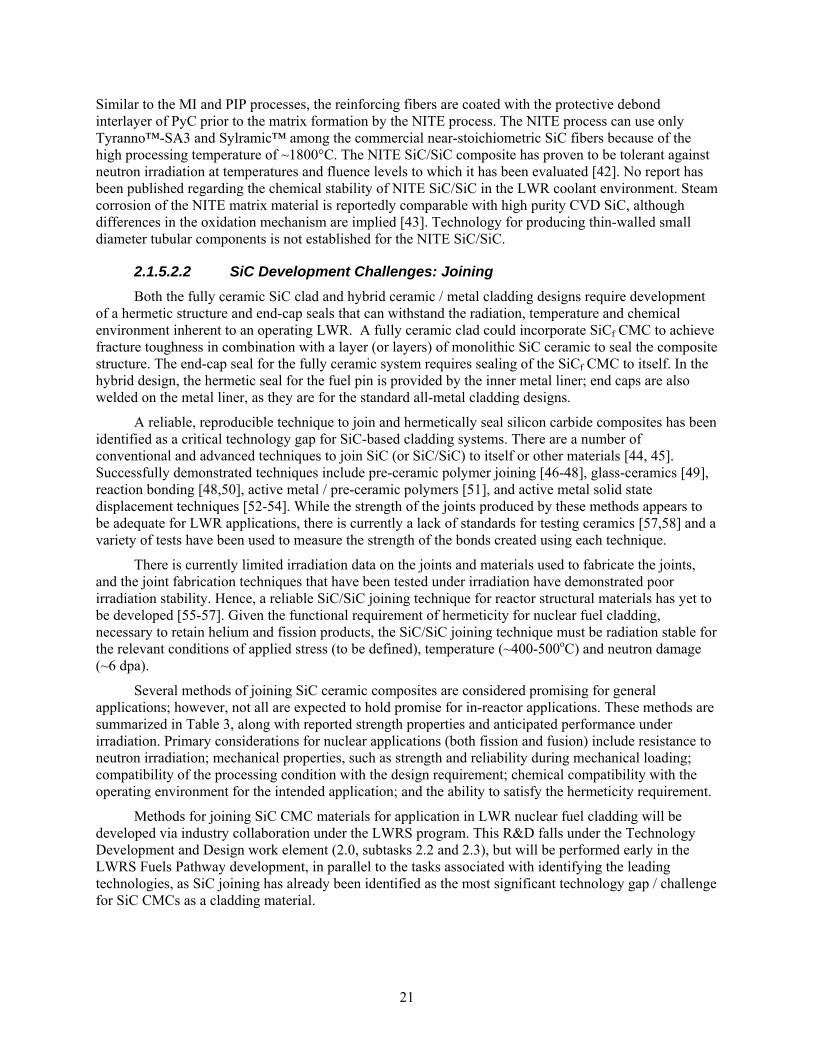
21
Similar to the MI and PIP processes, the reinforcing fibers are coated with the protective debond interlayer of PyC prior to the matrix formation by the NITE process. The NITE process can use only Tyranno™-SA3 and Sylramic™ among the commercial near-stoichiometric SiC fibers because of the high processing temperature of ~1800°C. The NITE SiC/SiC composite has proven to be tolerant against neutron irradiation at temperatures and fluence levels to which it has been evaluated [42]. No report has been published regarding the chemical stability of NITE SiC/SiC in the LWR coolant environment. Steam corrosion of the NITE matrix material is reportedly comparable with high purity CVD SiC, although differences in the oxidation mechanism are implied [43]. Technology for producing thin-walled small diameter tubular components is not established for the NITE SiC/SiC.
2.1.5.2.2 SiC Development Challenges: Joining
Both the fully ceramic SiC clad and hybrid ceramic / metal cladding designs require development of a hermetic structure and end-cap seals that can withstand the radiation, temperature and chemical environment inherent to an operating LWR. A fully ceramic clad could incorporate SiCf CMC to achieve fracture toughness in combination with a layer (or layers) of monolithic SiC ceramic to seal the composite structure. The end-cap seal for the fully ceramic system requires sealing of the SiCf CMC to itself. In the hybrid design, the hermetic seal for the fuel pin is provided by the inner metal liner; end caps are also welded on the metal liner, as they are for the standard all-metal cladding designs.
A reliable, reproducible technique to join and hermetically seal silicon carbide composites has been identified as a critical technology gap for SiC-based cladding systems. There are a number of conventional and advanced techniques to join SiC (or SiC/SiC) to itself or other materials [44, 45]. Successfully demonstrated techniques include pre-ceramic polymer joining [46-48], glass-ceramics [49], reaction bonding [48,50], active metal / pre-ceramic polymers [51], and active metal solid state displacement techniques [52-54]. While the strength of the joints produced by these methods appears to be adequate for LWR applications, there is currently a lack of standards for testing ceramics [57,58] and a variety of tests have been used to measure the strength of the bonds created using each technique.
There is currently limited irradiation data on the joints and materials used to fabricate the joints, and the joint fabrication techniques that have been tested under irradiation have demonstrated poor irradiation stability. Hence, a reliable SiC/SiC joining technique for reactor structural materials has yet to be developed [55-57]. Given the functional requirement of hermeticity for nuclear fuel cladding, necessary to retain helium and fission products, the SiC/SiC joining technique must be radiation stable for the relevant conditions of applied stress (to be defined), temperature (~400-500oC) and neutron damage (~6 dpa).
Several methods of joining SiC ceramic composites are considered promising for general applications; however, not all are expected to hold promise for in-reactor applications. These methods are summarized in Table 3, along with reported strength properties and anticipated performance under irradiation. Primary considerations for nuclear applications (both fission and fusion) include resistance to neutron irradiation; mechanical properties, such as strength and reliability during mechanical loading; compatibility of the processing condition with the design requirement; chemical compatibility with the operating environment for the intended application; and the ability to satisfy the hermeticity requirement.
Methods for joining SiC CMC materials for application in LWR nuclear fuel cladding will be developed via industry collaboration under the LWRS program. This R&D falls under the Technology Development and Design work element (2.0, subtasks 2.2 and 2.3), but will be performed early in the LWRS Fuels Pathway development, in parallel to the tasks associated with identifying the leading technologies, as SiC joining has already been identified as the most significant technology gap / challenge for SiC CMCs as a cladding material.
22
Table 3. Methods for joining SiC-based materials [88].
Joining Method Typical Reported
Strength Irradiation Performance References
Metal diffusion bonding ~150 MPa shear Expectedly good [52,59]
Transient eutectic-phase joining
~250 MPa tensile Expectedly good [57,60,63]
Glass-ceramic joining ~100 MPa shear Positive result reported
(EU program) [57,58, 64-67]
Brazing Various Generally poor; high activation
[62,65,80-83]
SiC reaction bonding ~200 MPa shear Expectedly unstable [76-79]
MAX-phase joining ~100 MPa shear Unknown [53, 68-71]
Pre-ceramic polymer joining
Tens MPa shear Expectedly unstable [69,71-75]
Transient liquid metal joining
No data Unknown ---
Selective area CVD No data Expectedly very good [61]
2.1.5.2.3 Environmental Behavior Criteria for Advanced Cladding
As discussed in section 1.2, zirconium alloys undergo significant reaction with reactor coolant leading to materials loss, hydriding and related loss of materials ductility under normal operating conditions. Under LOCA conditions zirconium alloys can undergo phase transition, loss of strength, exothermic reaction with steam, and associated (significant) hydrogen production. It is assumed that any advanced cladding must be demonstrated to outperform zircaloy under LOCA and normal operating conditions. This section focuses on environmental behavior criteria for SiC-based cladding designs, as they offer the most distinct departure from the current zirconium-based cladding (relative to corrosion resistant coatings on zirconium-based alloys, for instance).
The environmental threats facing SiC cladding under normal operating conditions include potential evolution in the microstructure/mechanical properties of the clad due to irradiation, interaction of the clad structure with the coolant, and the potential synergy of environmental conditions including irradiation and coolant interactions.
23
2.1.5.2.4 Normal Operation
Irradiation Stability Criteria
The stability of pure SiC (stoichiometric and devoid of grain boundary second phases) has been reviewed extensively in the literature [84 - 87] and briefly discussed in this program plan. It is known that at the temperatures of interest for LWR clad there is no effect of flux-rate dependence on damage and the total neutron damage (to stable materials) is the essential factor in evaluating radiation resistance. Without assuming power uprates or extended burn-up fuels, the SiC clad will see approximately 10-15 dpa, which for the nominal 300-400°C operating temperature is well above the saturation condition (~1 dpa). It is therefore assumed that a clad structure should be proven stable and resistant to micro cracks up to a minimum 10 dpa to be considered for LTR deployment. At present, two fiber types (Nicalon Type-S and Tyranno SA) with either graphite or SiC multilayer interphases and CVI SiC matrix have been demonstrated to be stable beyond these dose and temperature conditions. Stability, as defined in the LWR clad context, is the ability of the overall system, whether a fully ceramic or ceramic-metal hybrid system, to carry out its function within allowables of required strength, swelling, and maximum failure criteria (fission product release) of one rod per million. Presently there is insufficient information pertaining to the stability of any metallic liner/SiC interface or fuel-liner/fuel-SiC interface. As previously discussed, end cap sealing has been a historically difficult issue for SiC, although a recent report [88] highlights a number of methods which appear stable under relevant irradiation conditions. However, all of these issues would be addressed within the fission product release criteria.
Corrosion/Erosion
Under normal operating conditions for PWRs (temperature and pressure), pure SiC would be expected to form a semi-protective SiO2 layer, in effect protecting the surface [89 - 92]. As an example, Kim [90] reports an approximate factor of three difference between a boron sintered SiC ceramic and the better performing CVD SiC for a relatively high velocity 360°C coolant flow. In Kim’s work the CVD SiC recession was on the order of 0.05 mg/cm2 over a ten day period, or approximately 250 microns over a standard 4.5 year fuel lifetime (without irradiation or appropriate reactor chemistry). However, this assumes linear extrapolation (linear kinetics) of the Kim data from a relatively short test, or the lack of a truly protective oxide formation (leading to parabolic kinetics). Non-stoichiometric SiC-based materials have demonstrated even more significant mass loss, whether by corrosion or erosion [93]. This result is not surprising given that the presence of free silicon, or presumably other sintering aids residing at grain boundaries, has previously been shown to enhance corrosion for water temperatures as low as 290°C [89]. The mass loss, beyond any concerns regarding irradiation instability underlying the material loss, could raise issues as the very hard SiC particulates (or possibly SiO2) are transported through the coolant to heat exchangers and pumps. It is also conceivable that an irradiation-assisted-corrosion process that enhances the surface reaction may occur. In any event, mass loss with regard to secondary system effects and the potential compromise of the mechanical performance of the clad necessitate this as a selection criterion.
2.1.5.2.5 Off Normal Events
It is accepted that SiC will react more slowly than zirconium-based alloys with steam under LOCA or beyond design basis accident conditions. Near atmospheric pressure the reaction of steam with zirconium-based alloys and SiC [94] has been extensively studied and is well understood. While it is well known that metallic materials have a linear pressure dependence of mass loss, this dependence is generally not important over the pressure range associated with reactor transients (for zirconium-based alloys) and is hence ignored. However, as SiC has the potential for substantially greater performance than zirconium-based alloys, it becomes more important to understand the projected pressure/temperature of any beyond design basis accident and the physical mechanism of SiC reactions.

24
The relative cladding thickness loss of SiC with respect to zirconium-based alloys and other candidate cladding materials at both atmospheric and elevated pressures and temperature is now becoming understood as part of various national and international programs. For example, Figure 7 shows the mass loss for the three generic classes of advanced clad: alumina formers, chromia formers, and silica formers, as compared with zirconium-based alloys [95]. All the cladding with internally produced oxides outperformed zirconium-based alloys, with the CVD SiC showing about two orders of magnitude less thickness consumption at 1200°C. While the outperformance of any SiC-based clad under LOCA and beyond design basis accident conditions is assumed, the relative attractiveness and benefit of the clad (the ultimate economic driver) will depend on the quantitative determination of performance of the clad. For this reason a sufficient understanding of the clad performance under LOCA and/or design base accident conditions is required.
Figure 7. Clad thickness loss for candidate materials in flowing steam at 1 MPa.
2.1.5.2.6 Economic Analysis of SiC-Clad Nuclear Fuel Pins
Nuclear electricity production cost consists of two components: operation and management (O&M) costs and fuel costs. A review of historical data from 1995 up to the present points out that the fuel costs in current oxide-fueled nuclear reactors as a share of production cost of nuclear electricity have consistently remained at around 28% [96].
The impact of moving to SiC cladding on the required fuel enrichment will be heavily dependent on the specifics of the chosen fuel design. Causal factors will be any displaced fuel due to a thicker
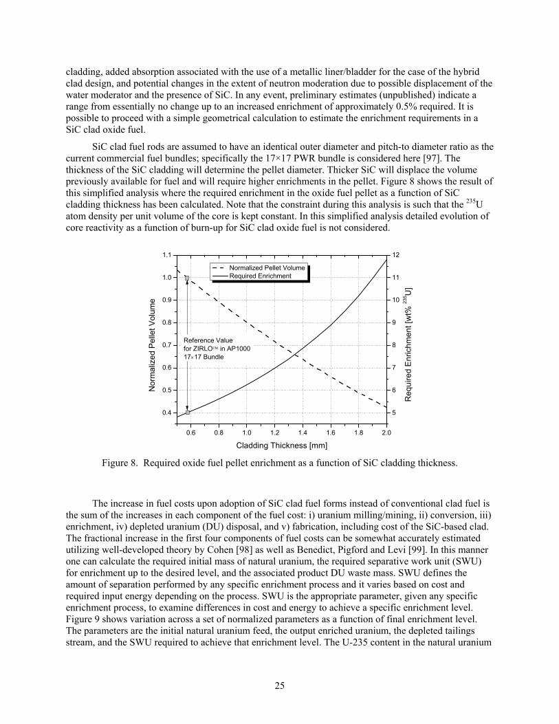
25
cladding, added absorption associated with the use of a metallic liner/bladder for the case of the hybrid clad design, and potential changes in the extent of neutron moderation due to possible displacement of the water moderator and the presence of SiC. In any event, preliminary estimates (unpublished) indicate a range from essentially no change up to an increased enrichment of approximately 0.5% required. It is possible to proceed with a simple geometrical calculation to estimate the enrichment requirements in a SiC clad oxide fuel.
SiC clad fuel rods are assumed to have an identical outer diameter and pitch-to diameter ratio as the current commercial fuel bundles; specifically the 17×17 PWR bundle is considered here [97]. The thickness of the SiC cladding will determine the pellet diameter. Thicker SiC will displace the volume previously available for fuel and will require higher enrichments in the pellet. Figure 8 shows the result of this simplified analysis where the required enrichment in the oxide fuel pellet as a function of SiC cladding thickness has been calculated. Note that the constraint during this analysis is such that the 235U atom density per unit volume of the core is kept constant. In this simplified analysis detailed evolution of core reactivity as a function of burn-up for SiC clad oxide fuel is not considered.
Figure 8. Required oxide fuel pellet enrichment as a function of SiC cladding thickness.
The increase in fuel costs upon adoption of SiC clad fuel forms instead of conventional clad fuel is
the sum of the increases in each component of the fuel cost: i) uranium milling/mining, ii) conversion, iii) enrichment, iv) depleted uranium (DU) disposal, and v) fabrication, including cost of the SiC-based clad. The fractional increase in the first four components of fuel costs can be somewhat accurately estimated utilizing well-developed theory by Cohen [98] as well as Benedict, Pigford and Levi [99]. In this manner one can calculate the required initial mass of natural uranium, the required separative work unit (SWU) for enrichment up to the desired level, and the associated product DU waste mass. SWU defines the amount of separation performed by any specific enrichment process and it varies based on cost and required input energy depending on the process. SWU is the appropriate parameter, given any specific enrichment process, to examine differences in cost and energy to achieve a specific enrichment level. Figure 9 shows variation across a set of normalized parameters as a function of final enrichment level. The parameters are the initial natural uranium feed, the output enriched uranium, the depleted tailings stream, and the SWU required to achieve that enrichment level. The U-235 content in the natural uranium
0.6 0.8 1.0 1.2 1.4 1.6 1.8 2.0
0.4
0.5
0.6
0.7
0.8
0.9
1.0
1.1
Normalized Pellet Volume Required Enrichment
Cladding Thickness [mm]
Nor
ma
lized
Pe
llet V
olum
e
Reference Value for ZIRLO in AP1000 1717 Bundle
5
6
7
8
9
10
11
12
Req
uire
d E
nric
hme
nt [w
t% 2
35U
]
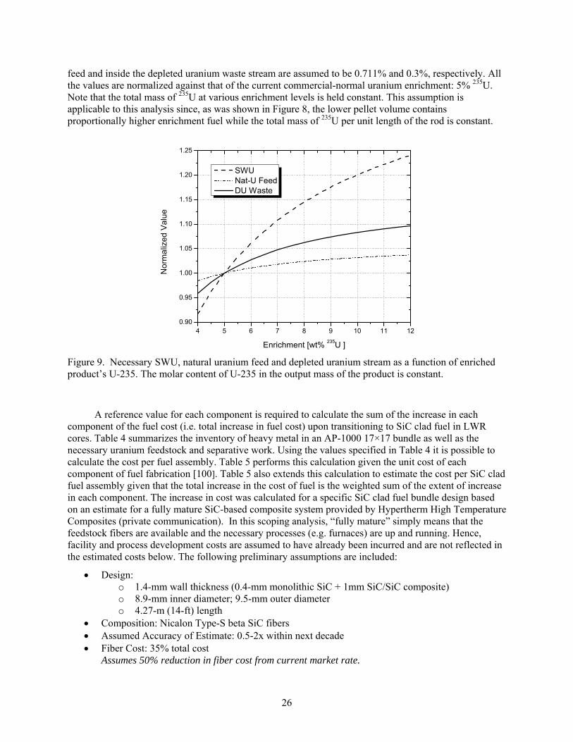
26
feed and inside the depleted uranium waste stream are assumed to be 0.711% and 0.3%, respectively. All the values are normalized against that of the current commercial-normal uranium enrichment: 5% 235U. Note that the total mass of 235U at various enrichment levels is held constant. This assumption is applicable to this analysis since, as was shown in Figure 8, the lower pellet volume contains proportionally higher enrichment fuel while the total mass of 235U per unit length of the rod is constant.
Figure 9. Necessary SWU, natural uranium feed and depleted uranium stream as a function of enriched product’s U-235. The molar content of U-235 in the output mass of the product is constant.
A reference value for each component is required to calculate the sum of the increase in each
component of the fuel cost (i.e. total increase in fuel cost) upon transitioning to SiC clad fuel in LWR cores. Table 4 summarizes the inventory of heavy metal in an AP-1000 17×17 bundle as well as the necessary uranium feedstock and separative work. Using the values specified in Table 4 it is possible to calculate the cost per fuel assembly. Table 5 performs this calculation given the unit cost of each component of fuel fabrication [100]. Table 5 also extends this calculation to estimate the cost per SiC clad fuel assembly given that the total increase in the cost of fuel is the weighted sum of the extent of increase in each component. The increase in cost was calculated for a specific SiC clad fuel bundle design based on an estimate for a fully mature SiC-based composite system provided by Hypertherm High Temperature Composites (private communication). In this scoping analysis, “fully mature” simply means that the feedstock fibers are available and the necessary processes (e.g. furnaces) are up and running. Hence, facility and process development costs are assumed to have already been incurred and are not reflected in the estimated costs below. The following preliminary assumptions are included:
Design: o 1.4-mm wall thickness (0.4-mm monolithic SiC + 1mm SiC/SiC composite) o 8.9-mm inner diameter; 9.5-mm outer diameter o 4.27-m (14-ft) length
Composition: Nicalon Type-S beta SiC fibers Assumed Accuracy of Estimate: 0.5-2x within next decade Fiber Cost: 35% total cost
Assumes 50% reduction in fiber cost from current market rate.
4 5 6 7 8 9 10 11 120.90
0.95
1.00
1.05
1.10
1.15
1.20
1.25
No
rma
lize
d V
alu
e
Enrichment [wt% 235U ]
SWU Nat-U Feed DU Waste
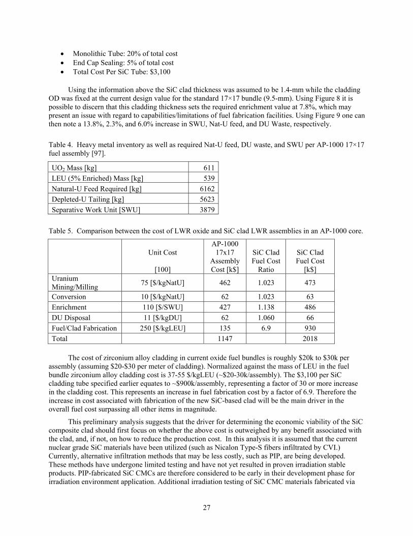
27
Monolithic Tube: 20% of total cost End Cap Sealing: 5% of total cost Total Cost Per SiC Tube: $3,100
Using the information above the SiC clad thickness was assumed to be 1.4-mm while the cladding
OD was fixed at the current design value for the standard 17×17 bundle (9.5-mm). Using Figure 8 it is possible to discern that this cladding thickness sets the required enrichment value at 7.8%, which may present an issue with regard to capabilities/limitations of fuel fabrication facilities. Using Figure 9 one can then note a 13.8%, 2.3%, and 6.0% increase in SWU, Nat-U feed, and DU Waste, respectively.
Table 4. Heavy metal inventory as well as required Nat-U feed, DU waste, and SWU per AP-1000 17×17 fuel assembly [97].
UO2 Mass [kg] 611
LEU (5% Enriched) Mass [kg] 539
Natural-U Feed Required [kg] 6162
Depleted-U Tailing [kg] 5623
Separative Work Unit [SWU] 3879
Table 5. Comparison between the cost of LWR oxide and SiC clad LWR assemblies in an AP-1000 core.
Unit Cost
[100]
AP-1000 17x17
Assembly Cost [k$]
SiC Clad Fuel Cost
Ratio
SiC Clad Fuel Cost
[k$] Uranium Mining/Milling
75 [$/kgNatU] 462 1.023 473
Conversion 10 [$/kgNatU] 62 1.023 63
Enrichment 110 [$/SWU] 427 1.138 486
DU Disposal 11 [$/kgDU] 62 1.060 66
Fuel/Clad Fabrication 250 [$/kgLEU] 135 6.9 930
Total 1147 2018
The cost of zirconium alloy cladding in current oxide fuel bundles is roughly $20k to $30k per
assembly (assuming $20-$30 per meter of cladding). Normalized against the mass of LEU in the fuel bundle zirconium alloy cladding cost is 37-55 $/kgLEU (~$20-30k/assembly). The $3,100 per SiC cladding tube specified earlier equates to ~$900k/assembly, representing a factor of 30 or more increase in the cladding cost. This represents an increase in fuel fabrication cost by a factor of 6.9. Therefore the increase in cost associated with fabrication of the new SiC-based clad will be the main driver in the overall fuel cost surpassing all other items in magnitude.
This preliminary analysis suggests that the driver for determining the economic viability of the SiC composite clad should first focus on whether the above cost is outweighed by any benefit associated with the clad, and, if not, on how to reduce the production cost. In this analysis it is assumed that the current nuclear grade SiC materials have been utilized (such as Nicalon Type-S fibers infiltrated by CVI.) Currently, alternative infiltration methods that may be less costly, such as PIP, are being developed. These methods have undergone limited testing and have not yet resulted in proven irradiation stable products. PIP-fabricated SiC CMCs are therefore considered to be early in their development phase for irradiation environment application. Additional irradiation testing of SiC CMC materials fabricated via

28
PIP techniques will be required to determine applicability in a reactor environment. Economics may require further investigation of newer, lower cost techniques to ensure that SiC CMC cladding is a viable option. It is also noted that arguments have been made regarding significantly reduced cost of composite constituents (i.e. fibers) as well as the fabrication costs. Current very high production fibers such as polyacrylonitrile (PAN) based graphite fibers are approximately 40x less expensive through utilization of much lower cost raw materials. Following the initial design selection the above assumptions can be individually considered to determine a more accurate cost estimate for the clad.
2.2 Technology Development and Design
Work conducted under the Technology Development and Design work element (2.0) will focus on conceptual cladding design and preliminary testing (screening) of leading cladding technologies identified in the Technology Selection work element (1.0). A suite of materials characterization tests and property measurements will be conducted to fill gaps in the technology database for each candidate material and cladding design. This data will, in turn, be used to refine the modeling simulations of the fuel-clad system under normal and off-normal reactor conditions, and modeling results will be integrated with the conceptual design process. Conceptual fuel rod designs will be developed for each advanced cladding option and these designs will undergo preliminary analysis and review in anticipation of developing an engineering design. Tests conducted within element 2.0 will focus on sample coupons and short cylindrical pieces to acquire the necessary material properties and preliminary performance data. It is anticipated that this work element, which will consider multiple technologies in parallel, will take approximately three years to complete. The general work process that will be adopted for each technology investigated in work element 2.0 is illustrated in Figure 10.
2.2.1 Test Specimen Technical and Functional Requirements
Once industry requirements/standards have been defined and candidate technologies have been identified for development testing, an initial scoping analysis should be performed to determine test specimen design and fabrication requirements. The “conceptual design” under the Technology Development work element refers to the overall design for the fuel cladding in a commercial reactor, including geometric details such as cladding thickness, inner / outer diameter, overall length, and end-cap design in addition to fabrication details, such as the overall cladding composition, layering techniques (e.g. SiCf CMC and monolithic SiC, or SiCf with a metallic liner), fabrication methods and processing techniques. This conceptual design will be used in the preliminary safety analyses that will assess the expected performance potential for the proposed cladding design (task 1.4). The full length rod conceptual design will later be translated to conceptual and engineering designs (for options selected for further development testing) for rodlets intended for irradiation in a test reactor, where a rodlet is defined as a sealed cladding tube of reduced length relative to a commercial fuel pin. Conceptual rodlets, derived from the full length fuel rod design, must be designed such that they can eventually be demonstrated in a test reactor.
Actual tests conducted under work element 2.0 will focus on sample coupons and short cylindrical sections. The composition of the test specimens for preliminary materials characterization will be based on each conceptual cladding design, maintaining the correct layering, composition, etc. as the full length fuel rod design. The size and configuration of the test specimens will be determined by the requirements of each test or measurement device.
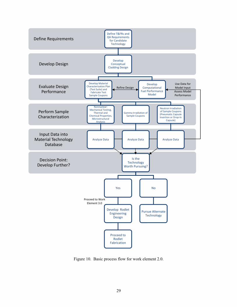
29
Figure 10. Basic process flow for work element 2.0.
Input Data into Material Technology
Database
Perform Sample Characterization
Evaluate Design Performance
Develop Design
Define RequirementsDefine T&FRs and QA Requirements for Candidate Technology
Develop Conceptual
Cladding Design
Develop Computational
Fuel Performance Model
Develop Material Characterization Plan
(Test Suite) and Fabricate Test
Sample Coupons
Nonnuclear: Mechanical Testing,
Thermal and Chemical Properties,
Microstructural Analysis
Analyze Data
Gamma Irradiation of Sample Coupons
Analyze Data
Neutron Irradiation of Sample Coupons (Pneumatic Capsule Insertion or Drop‐In
Capsule)
Analyze Data
Decision Point: Develop Further?
Is the Technology
Worth Pursuing?
Yes
Develop Rodlet Engineering
Design
Proceed to Rodlet
Fabrication
No
Pursue Alternate Technology
Refine DesignUse Data for Model Input Assess Model Performance
Proceed to Work Element 3.0

30
In addition to the challenges associated with material and dimensional properties of the experiment assembly, neutronic and thermal hydraulic design compatibility must be taken into account in defining the technical and functional requirements for a conceptual cladding design that would later be tested in the intended geometry under the Technology Demonstration work element (3.0). Although the technology development work element may include testing of coupon size samples, the conceptual rodlet design must be taken into account in determining what type of development testing is relevant to the anticipated final design for each candidate cladding technology. Materials tests may include flat coupons or short cylindrical tubes depending on the property being measured. Acquired data will to be used to support iterative computational modeling efforts. In moving forward to the rodlet conceptual and engineering designs, the design must take into account a variety of challenges for in-core implementation.
Fuel pin neutronics design considerations must include the implications of replacing the zirconium-based cladding with a potentially thicker cladding material that could then require higher uranium enrichment as a result of the reduced volume available for fuel. Expectations of higher uranium enrichment (possibly on the order of ~6-8% for SiC cladding options), coupled with higher uranium mass, suggest that the redesigned, advanced fuel pin could exceed the limit of criticality for a single assembly dispersed in water. Full scale modeling of the core with the proposed advanced fuel pins will be required under steady-state and transient conditions over the entire burn-up regime to fully characterize the expected reactor performance with the alternate pin design.
Thermal hydraulics design considerations must also be taken into account when developing a conceptual advanced pin design. If the pin is allowed to have a larger outer diameter than the current fuel pin designs (not currently allowed in the advanced cladding design assumptions), the smaller P/D that could result from thicker cladding material would displace the reactor coolant (moderator), requiring larger pressure drops to safely extract the power generated in each fuel rod. The roughness on the outer surface of the fuel pin cladding will also affect heat transfer; the beneficial or detrimental nature of the surface roughness must be tested and characterized. Integrated testing will be required to qualify the modified assembly geometry (relative to conventional 17x17 PWR or 10x10 BWR geometry) to ensure that adequate cooling can be maintained under both steady-state and transient scenarios.
The defined technical and functional requirements will also address the necessary quality requirements for the final rodlet design and for sample coupons to be used in initial characterization tests intended for preliminary screening of each technology. A graded approach for quality requirements will be used in the design and development phase, as described in the quality procedure for research and development within the LWRS Program [19]; however, it should be taken into consideration during design and development testing that final product fabrication for irradiation demonstrations will require meeting NQA-1 Part I and II requirements. Therefore, samples used for material characterization to support irradiation testing/nuclear demonstrations must meet a higher quality standard/rigor compared to samples that will be used to develop characterization methodologies and/or screen technologies for further development.
2.2.2 Advanced Cladding Conceptual Design
Early conceptual design of each candidate fuel clad system will be performed to assess if the concept can be fabricated based on cladding materials requirements and available feedstock and fabrication facilities; if the design can be tested in existing nonnuclear and nuclear test facilities; if there are significant technology gaps specific to the conceptual design; and to determine when the concept might be ready for rodlet testing in a test reactor facility. Conceptual designs will allow for preliminary design review by facility safety committees and will offer opportunity for comment and buy-in from stakeholders before the technology development testing begins in earnest.
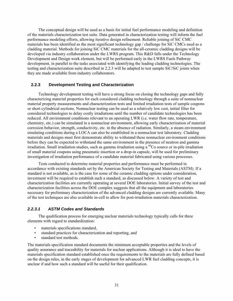
31
The conceptual design will be used as a basis for initial fuel performance modeling and definition of the materials characterization test suite. Data generated in characterization testing will inform the fuel performance modeling efforts, allowing iterative design refinement. Reliable joining of SiC CMC materials has been identified as the most significant technology gap / challenge for SiC CMCs used as a cladding material. Methods for joining SiC CMC materials for the all-ceramic cladding designs will be developed via industry collaboration under the LWRS program. This R&D falls under the Technology Development and Design work element, but will be performed early in the LWRS Fuels Pathway development, in parallel to the tasks associated with identifying the leading cladding technologies. The testing and characterization suite described in 2.2.3 will be adapted to test sample SiC/SiC joints when they are made available from industry collaborators.
2.2.3 Development Testing and Characterization
Technology development testing will have a strong focus on closing the technology gaps and fully characterizing material properties for each considered cladding technology through a suite of nonnuclear material property measurements and characterization tests and limited irradiation tests of sample coupons or short cylindrical sections. Nonnuclear testing can be used as a relatively low cost, initial filter for considered technologies to delay costly irradiations until the number of candidate technologies has been reduced. All environment conditions relevant to an operating LWR (i.e. water flow rate, temperature, chemistry, etc.) can be simulated in a nonnuclear environment, allowing early characterization of material corrosion behavior, strength, conductivity, etc. in the absence of radiation. Similarly, a steam environment emulating conditions during a LOCA can also be established in a nonnuclear test laboratory. Cladding materials and designs must first demonstrate ability to withstand these nonnuclear environment conditions before they can be expected to withstand the same environment in the presence of neutron and gamma irradiation. Small irradiation studies, such as gamma irradiation using a 60Co source or in-pile irradiation of small material coupons using pneumatic insertion or a drop-in capsule, will be used for preliminary investigation of irradiation performance of a candidate material fabricated using various processes.
Tests conducted to determine material properties and performance must be performed in accordance with existing standards set by the American Society for Testing and Materials (ASTM). If a standard is not available, as is the case for some of the ceramic cladding options under consideration, investment will be required to establish such a standard, as discussed below. A variety of test and characterization facilities are currently operating at several DOE laboratories. Initial survey of the test and characterization facilities across the DOE complex suggests that all the equipment and laboratories necessary for preliminary characterization of the advanced cladding designs are currently available. Many of the test techniques are also available in-cell to allow for post-irradiation materials characterization.
2.2.3.1 ASTM Codes and Standards
The qualification process for emerging nuclear materials technology typically calls for three elements with regard to standardization:
• materials specifications standard, • standard practices for characterization and reporting, and • standard test methods.
The materials specification standard documents the minimum acceptable properties and the levels of quality assurance and traceability for materials for nuclear applications. Although it is ideal to have the materials specification standard established once the requirements to the materials are fully defined based on the design rules, in the early stages of development for advanced LWR fuel cladding concepts, it is unclear if and how such a standard will be useful for their qualification.
32
The standard practices for characterization and reporting define the outline of the methods for generating and reporting the properties data. These standard practices will specify the test methods for determining various properties of materials and/or test articles for use in the design and evaluation of LWR fuel and core components. They may refer to test methods that have already been published as ASTM (or other) standards, ASTM standards modified to meet the specific requirements, and new test standards which are required for testing specific components. Such standards are useful as guidelines for the materials/components suppliers to generate the material properties data for transmission to their customers in a certifiable manner. It is likely that these standards will have to be established separately for specific LWR fuel cladding concept classes; e.g., for semi-brittle ceramics, pseudo-ductile continuous fiber ceramic composites, and ceramic composite – metal hybrids.
The test method standards define the details of test procedures, from sample preparation to reporting, of the individual test methods. Typical properties required for nuclear component design and material qualification include thermo-physical (coefficient of thermal expansion, thermal diffusivity/conductivity) and mechanical properties (elastic constants and strength in relation with various failure modes). Establishment of these individual test standards through a full-consensus standard development process in ASTM is considered mandatory to be able to provide credible properties data (for materials/component suppliers, users, or their contractors). In order to define the exact needs for the test method standards, it is essential to determine the key design properties, performance measures and potential failure modes for specific applications. However, it is obvious that for the development of ceramic composite-based fuel cladding, the essential test standard needs include those for various mechanical properties of tubular geometry test articles. While the individual standards will be for specific properties and specific test methods, they may remain more or less generic in terms of the material class and the application.
Existing ASTM test standards are insufficient to qualify ceramic composite or composite-based components for use in LWR fuels and cores because they are limited to basic mechanical properties tested in simple test specimen geometries. For example, adequate test standards for axial, hoop, lateral shear, or joint strength, which correspond to some of the anticipated failure modes for fuel cladding and clad end plugs, are currently unavailable. ASTM test standards that are presently available specifically for ceramic matrix composites are listed in Table 6.
The appropriate venue for the desired standards development will be ASTM Committee C28 on Advanced Ceramics. ASTM Subcommittee C28.07 on Ceramic Matrix Composites is appropriate to develop the standards for the majority of the composite component properties and specifications, whereas other ASTM committees or subcommittees may be adequate for certain test methods that are not specifically for ceramic matrix composites. The Nuclear Composite Working Group has been established in ASTM Subcommittee C28.07 on Ceramic Matrix Composites and is actively developing standards relevant to ceramic composites for nuclear applications. Support to the Working Group activity is required to draft the needed test standards, provide support for the standard approval process, and provide coordination of round-robin testing as required.
The preliminary plan for the current LWR program supporting development of ASTM standards is given in Table 7. Priority was assigned based on the obvious requirement for the fuel cladding to retain FP gas and maintain structural integrity under the internal pressure loading caused by the FP gas build-up and potential fuel swelling. Properties at elevated temperatures are considered of secondary importance based on the understanding that the mechanical properties of SiC ceramics and composites (in a stoichiometric and crystalline form) do not deteriorate up to ~1000°C (at the minimum) as compared to those at room temperature. However, it is important to note that the development items and priority will evolve as the failure mode analysis and the design rule development proceed.
For metallic materials and components that are non-composited and meso-scopically homogeneous, test standards have extensively been developed. The test standards published and

33
maintained by ASTM International include those for tensile (E8/E8M, E21), compressive (E9, E209), hardness (E10, E18, E384), impact (E23), elastic (E111, E143), creep and/or rupture (E139, E292, E328, E647), bend (E290), and toughness / notch sensitivity (E399, E561, E602). For the metallic materials, tubular geometry components with outer diameter smaller than ~1” are considered “small diameter” tubes that shall be tested as the whole tube for mechanical properties, whereas the larger diameter tubes may be tested using the sectioned specimens. Because the LWR fuel rods will always be categorized as the small diameter per this criterion, the fuel cladding shall be tested as the whole tube. Within the above-mentioned ASTM test standards, those listed in Table 8 have been written specifically considering the potential use of the small diameter tubular specimens. As can be seen, standards for some of the potentially important failure modes for the metallic fuel rods, such as the burst (or hoop tension) strength and fracture toughness, are not readily available. Therefore, in cases for which the metallic material establishes the primary (or the only) structural layer for the advanced fuel cladding, development of new test standards for mechanical properties of small diameter metallic tubes may be necessary.
Table 6. Standard test methods for ceramic matrix composites presently approved or being developed by ASTM International (as of April 2012).
Standard Description
C1275-10 Standard Test Method for Monotonic Tensile Behavior of Continuous Fiber-Reinforced Advanced Ceramics with Solid Rectangular Cross-Section Test Specimens at Ambient Temperature
C1292-10 Standard Test Method for Shear Strength of Continuous Fiber-Reinforced Advanced Ceramics at Ambient Temperatures
C1337-10 Standard Test Method for Creep and Creep Rupture of Continuous Fiber-Reinforced Ceramic Composites under Tensile Loading at Elevated Temperatures
C1341-06 Standard Test Method for Flexural Properties of Continuous Fiber-Reinforced Advanced Ceramic Composites
C1358-11 Standard Test Method for Monotonic Compressive Strength Testing of Continuous Fiber-Reinforced Advanced Ceramics with Solid Rectangular Cross-Section Test Specimens at Ambient Temperatures
C1359-11 Standard Test Method for Monotonic Tensile Strength Testing of Continuous Fiber-Reinforced Advanced Ceramics With Solid Rectangular Cross-Section Test Specimens at Elevated Temperatures
C1360-10 Standard Practice for Constant-Amplitude, Axial, Tension-Tension Cyclic Fatigue of Continuous Fiber-Reinforced Advanced Ceramics at Ambient Temperatures
C1425-11 Standard Test Method for Interlaminar Shear Strength of 1-D and 2-D Continuous Fiber-Reinforced Advanced Ceramics at Elevated Temperatures
C1468-06 Standard Test Method for Transthickness Tensile Strength of Continuous Fiber-Reinforced Advanced Ceramics at Ambient Temperature
C1469-10 Standard Test Method for Shear Strength of Joints of Advanced Ceramics at Ambient Temperature
C1557-03 (2008)
Standard Test Method for Tensile Strength and Young's Modulus of Fibers
WK32767* New Test Method for Monotonic Axial Tensile Properties of Continuous Fiber-Reinforced Advanced Ceramic Tubular Test Specimens at Ambient Temperature
*Work item number in ASTM standard development process.
34
Table 7. Preliminary plan for ASTM standards development.
Priority Group I (Near-Term)
Test method for axial tensile properties of CMC tubular test specimens at ambient temperature*
Test method for hoop tensile (burst) properties of CMC tubular test specimens at ambient temperature
Test method for flexural properties of CMC tubular test specimens at ambient temperature* Test method for shear strength of adhesive joint of advanced ceramics at ambient
temperature Test method for acoustic emission measurement for CMC at ambient temperature
Priority Group II (Mid-Term)
Standard practice for testing ceramic matrix composite for nuclear reactor components Test method for strength of end plug joint for small diameter CMC tube at ambient
temperature. Test method for strength of braze joint of advanced ceramics at ambient temperature (Additional mechanical test methods as identified necessary)** (Test methods for various mechanical properties at elevated temperatures)** (Method for non-destructive evaluation as identified necessary)**
Priority Group III (Long-Term)
(Standard specification for ceramic matrix composite for light water reactor fuel rod components)**
(Standard specification for ceramic matrix composites for light water reactor fuel channel box components)**
(Environment effect test methods as identified necessary)** *Activity to be supported also by other DOE program(s). **Items in parentheses are examples of standards need to be discussed as the program evolves. Table 8. ASTM test standards that are applicable for determining mechanical properties of small diameter tubular components of metallic materials.
Standard Description
E8/E8M-11 Standard Test Methods for Tension Testing of Metallic Materials
E21-09 Standard Test Methods for Elevated Temperature Tension Tests of Metallic Materials
E139-11 Standard Test Methods for Conducting Creep, Creep-Rupture, and Stress-Rupture Tests of Metallic Materials
2.2.3.2 Materials Characterization Techniques
The physical properties of ceramics and ceramic based composite materials are strongly tied to microstructure. For monolithic ceramics, pores and micron size cracks will influence both mechanical and thermal properties. For fiber-based composite materials the bond between fiber and matrix plays an important role in overall performance. To assist in the design and deployment of new ceramic-based fuel cladding materials there is need for a characterization approach that relates the fundamental response of the constituents to the overall performance of the composite. This approach will provide valuable information to help refine fabrication technologies and will provide critical input data and validation metrics for computational materials science models. Many of the characterization tools are non-destructive in nature and may be suitable for future quality and process control measurements.
There are many challenges related to the characterization of physical properties of ceramic-based cladding materials. Silicon carbide CMCs are a leading candidate for advance cladding material and provide an illustrative example of the challenges related to materials characterization. CMCs are heterogeneous and anisotropic; as a result, the measurement of thermo-mechanical properties depends on length scale and direction.
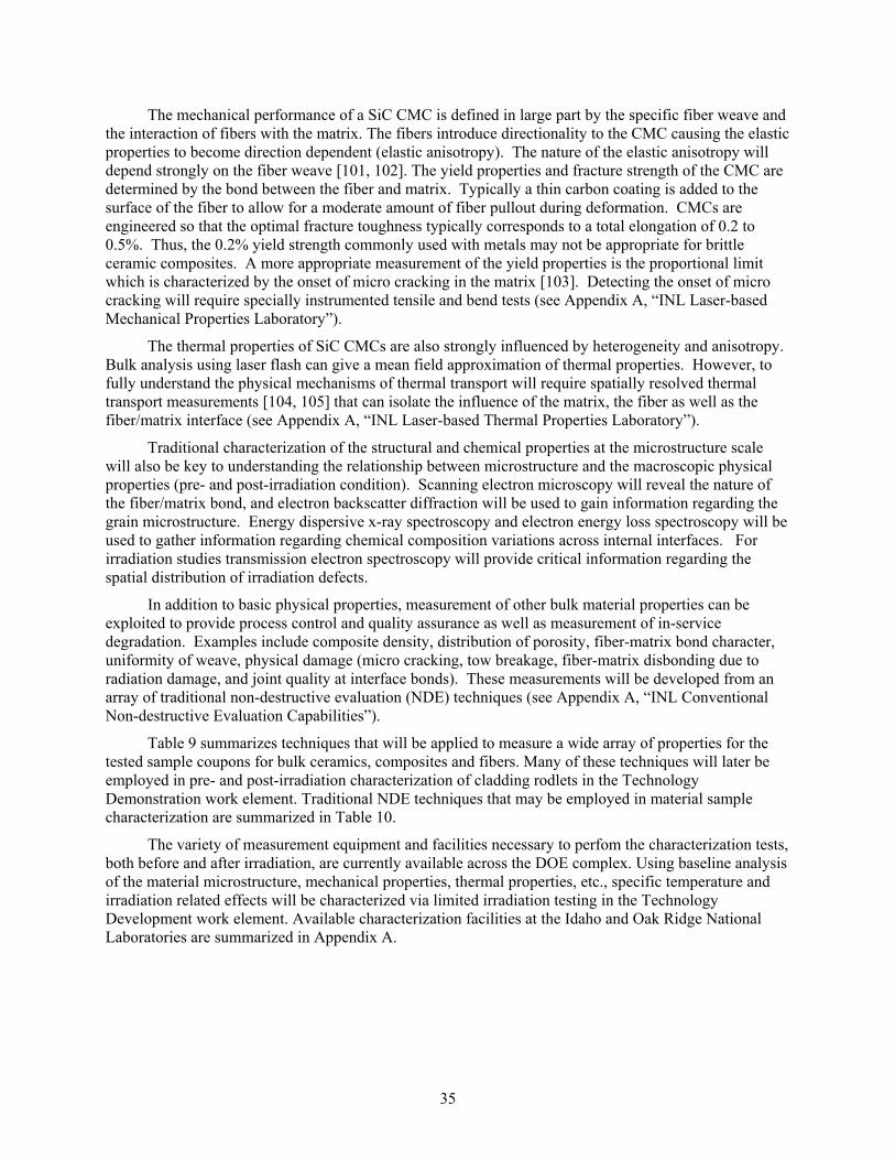
35
The mechanical performance of a SiC CMC is defined in large part by the specific fiber weave and the interaction of fibers with the matrix. The fibers introduce directionality to the CMC causing the elastic properties to become direction dependent (elastic anisotropy). The nature of the elastic anisotropy will depend strongly on the fiber weave [101, 102]. The yield properties and fracture strength of the CMC are determined by the bond between the fiber and matrix. Typically a thin carbon coating is added to the surface of the fiber to allow for a moderate amount of fiber pullout during deformation. CMCs are engineered so that the optimal fracture toughness typically corresponds to a total elongation of 0.2 to 0.5%. Thus, the 0.2% yield strength commonly used with metals may not be appropriate for brittle ceramic composites. A more appropriate measurement of the yield properties is the proportional limit which is characterized by the onset of micro cracking in the matrix [103]. Detecting the onset of micro cracking will require specially instrumented tensile and bend tests (see Appendix A, “INL Laser-based Mechanical Properties Laboratory”).
The thermal properties of SiC CMCs are also strongly influenced by heterogeneity and anisotropy. Bulk analysis using laser flash can give a mean field approximation of thermal properties. However, to fully understand the physical mechanisms of thermal transport will require spatially resolved thermal transport measurements [104, 105] that can isolate the influence of the matrix, the fiber as well as the fiber/matrix interface (see Appendix A, “INL Laser-based Thermal Properties Laboratory”).
Traditional characterization of the structural and chemical properties at the microstructure scale will also be key to understanding the relationship between microstructure and the macroscopic physical properties (pre- and post-irradiation condition). Scanning electron microscopy will reveal the nature of the fiber/matrix bond, and electron backscatter diffraction will be used to gain information regarding the grain microstructure. Energy dispersive x-ray spectroscopy and electron energy loss spectroscopy will be used to gather information regarding chemical composition variations across internal interfaces. For irradiation studies transmission electron spectroscopy will provide critical information regarding the spatial distribution of irradiation defects.
In addition to basic physical properties, measurement of other bulk material properties can be exploited to provide process control and quality assurance as well as measurement of in-service degradation. Examples include composite density, distribution of porosity, fiber-matrix bond character, uniformity of weave, physical damage (micro cracking, tow breakage, fiber-matrix disbonding due to radiation damage, and joint quality at interface bonds). These measurements will be developed from an array of traditional non-destructive evaluation (NDE) techniques (see Appendix A, “INL Conventional Non-destructive Evaluation Capabilities”).
Table 9 summarizes techniques that will be applied to measure a wide array of properties for the tested sample coupons for bulk ceramics, composites and fibers. Many of these techniques will later be employed in pre- and post-irradiation characterization of cladding rodlets in the Technology Demonstration work element. Traditional NDE techniques that may be employed in material sample characterization are summarized in Table 10.
The variety of measurement equipment and facilities necessary to perfom the characterization tests, both before and after irradiation, are currently available across the DOE complex. Using baseline analysis of the material microstructure, mechanical properties, thermal properties, etc., specific temperature and irradiation related effects will be characterized via limited irradiation testing in the Technology Development work element. Available characterization facilities at the Idaho and Oak Ridge National Laboratories are summarized in Appendix A.
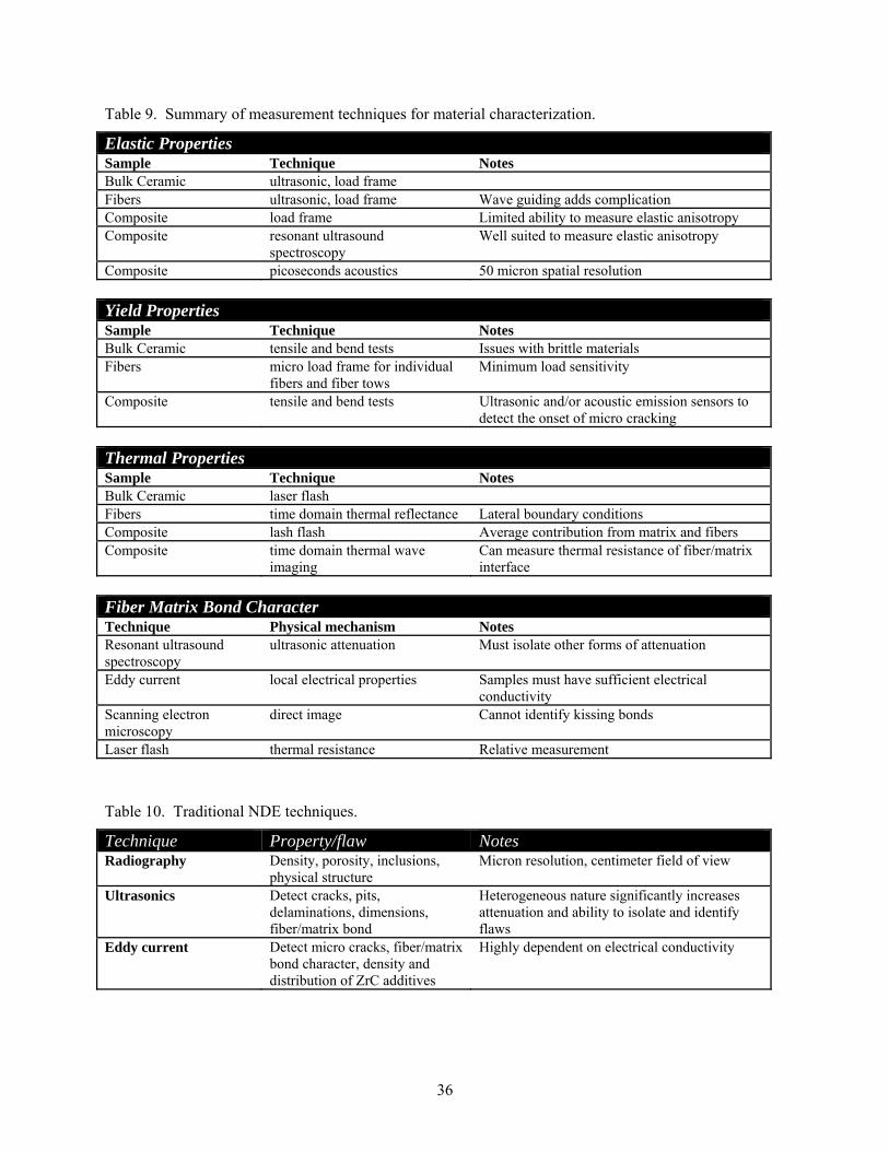
36
Table 9. Summary of measurement techniques for material characterization.
Elastic Properties Sample Technique Notes Bulk Ceramic ultrasonic, load frame Fibers ultrasonic, load frame Wave guiding adds complication Composite load frame Limited ability to measure elastic anisotropy Composite resonant ultrasound
spectroscopy Well suited to measure elastic anisotropy
Composite picoseconds acoustics 50 micron spatial resolution
Yield Properties Sample Technique Notes Bulk Ceramic tensile and bend tests Issues with brittle materials Fibers micro load frame for individual
fibers and fiber tows Minimum load sensitivity
Composite tensile and bend tests Ultrasonic and/or acoustic emission sensors to detect the onset of micro cracking
Thermal Properties Sample Technique Notes Bulk Ceramic laser flash Fibers time domain thermal reflectance Lateral boundary conditions Composite lash flash Average contribution from matrix and fibers Composite time domain thermal wave
imaging Can measure thermal resistance of fiber/matrix interface
Fiber Matrix Bond Character Technique Physical mechanism Notes Resonant ultrasound spectroscopy
ultrasonic attenuation Must isolate other forms of attenuation
Eddy current local electrical properties Samples must have sufficient electrical conductivity
Scanning electron microscopy
direct image Cannot identify kissing bonds
Laser flash thermal resistance Relative measurement
Table 10. Traditional NDE techniques.
Technique Property/flaw Notes Radiography Density, porosity, inclusions,
physical structure Micron resolution, centimeter field of view
Ultrasonics Detect cracks, pits, delaminations, dimensions, fiber/matrix bond
Heterogeneous nature significantly increases attenuation and ability to isolate and identify flaws
Eddy current Detect micro cracks, fiber/matrix bond character, density and distribution of ZrC additives
Highly dependent on electrical conductivity
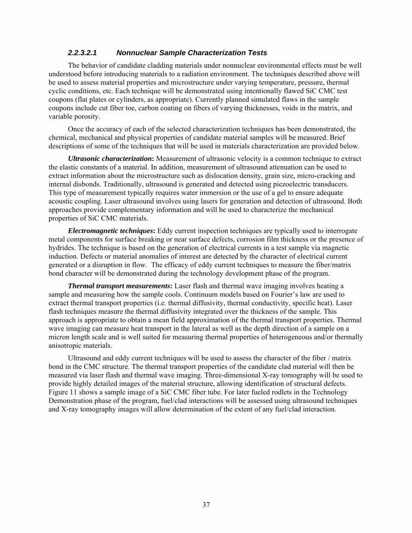
37
2.2.3.2.1 Nonnuclear Sample Characterization Tests
The behavior of candidate cladding materials under nonnuclear environmental effects must be well understood before introducing materials to a radiation environment. The techniques described above will be used to assess material properties and microstructure under varying temperature, pressure, thermal cyclic conditions, etc. Each technique will be demonstrated using intentionally flawed SiC CMC test coupons (flat plates or cylinders, as appropriate). Currently planned simulated flaws in the sample coupons include cut fiber toe, carbon coating on fibers of varying thicknesses, voids in the matrix, and variable porosity.
Once the accuracy of each of the selected characterization techniques has been demonstrated, the chemical, mechanical and physical properties of candidate material samples will be measured. Brief descriptions of some of the techniques that will be used in materials characterization are provided below.
Ultrasonic characterization: Measurement of ultrasonic velocity is a common technique to extract the elastic constants of a material. In addition, measurement of ultrasound attenuation can be used to extract information about the microstructure such as dislocation density, grain size, micro-cracking and internal disbonds. Traditionally, ultrasound is generated and detected using piezoelectric transducers. This type of measurement typically requires water immersion or the use of a gel to ensure adequate acoustic coupling. Laser ultrasound involves using lasers for generation and detection of ultrasound. Both approaches provide complementary information and will be used to characterize the mechanical properties of SiC CMC materials.
Electromagnetic techniques: Eddy current inspection techniques are typically used to interrogate metal components for surface breaking or near surface defects, corrosion film thickness or the presence of hydrides. The technique is based on the generation of electrical currents in a test sample via magnetic induction. Defects or material anomalies of interest are detected by the character of electrical current generated or a disruption in flow. The efficacy of eddy current techniques to measure the fiber/matrix bond character will be demonstrated during the technology development phase of the program.
Thermal transport measurements: Laser flash and thermal wave imaging involves heating a sample and measuring how the sample cools. Continuum models based on Fourier’s law are used to extract thermal transport properties (i.e. thermal diffusivity, thermal conductivity, specific heat). Laser flash techniques measure the thermal diffusivity integrated over the thickness of the sample. This approach is appropriate to obtain a mean field approximation of the thermal transport properties. Thermal wave imaging can measure heat transport in the lateral as well as the depth direction of a sample on a micron length scale and is well suited for measuring thermal properties of heterogeneous and/or thermally anisotropic materials.
Ultrasound and eddy current techniques will be used to assess the character of the fiber / matrix bond in the CMC structure. The thermal transport properties of the candidate clad material will then be measured via laser flash and thermal wave imaging. Three-dimensional X-ray tomography will be used to provide highly detailed images of the material structure, allowing identification of structural defects. Figure 11 shows a sample image of a SiC CMC fiber tube. For later fueled rodlets in the Technology Demonstration phase of the program, fuel/clad interactions will be assessed using ultrasound techniques and X-ray tomography images will allow determination of the extent of any fuel/clad interaction.
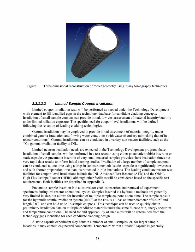
38
Figure 11. Three dimesional reconstruction of rodlet geometry using X-ray tomography techniques.
2.2.3.2.2 Limited Sample Coupon Irradiation
Limited coupon irradiation tests will be performed as needed under the Technology Development work element to fill identified gaps in the technology database for candidate cladding concepts. Irradiation of small sample coupons can provide initial, low cost assessment of material integrity/stability under limited radiation exposure. The specific need for coupon-level irradiations will be defined following the selection of leading cladding technologies.
Gamma irradiation may be employed to provide initial assessment of material integrity under combined gamma irradiation and flowing water conditions (with water chemistry mimicking that of in-reactor conditions). Gamma irradiations can be conducted in a variety non-reactor facilities, such as the 60Co gamma irradiation facility at INL.
Limited neutron irradiation needs are expected in the Technology Development program phase. Irradiation of small samples will be performed in a test reactor using either pneumatic (rabbit) insertion or static capsules. A pneumatic insertion of very small material samples provides short irradiation times but very rapid data results to inform initial scoping studies. Irradiation of a large number of sample coupons can be conducted at one time using a drop-in (uninstrumented) “static” capsule at significantly lower cost and with shorter preparation time than instrumented in-pile irradiations. The leading candidate reactor test facilities for coupon-level irradiations include the INL Advanced Test Reactor (ATR) and the ORNL High Flux Isotope Reactor (HFIR), although other facilities will be considered based on the specific test requirements. Both facilities are described in Appendix B.
Pneumatic sample insertion into a test reactor enables insertion and removal of experiment specimens during test reactor operational cycles. Samples inserted via hydraulic methods are generally very limited in size, but allows for insertion of multiple sample coupons at one time. The sample capsule for the hydraulic shuttle irradiation system (HSIS) at the INL ATR has an inner diameter of 0.495” and length 2.07” and can hold up to 16 sample coupons. This technique can be used to quickly obtain preliminary irradiation data on multiple candidate materials under the same fluence rate, energy spectrum and temperature conditions. The need for and applicability of such a test will be determined from the technology gaps identified for each candidate cladding design.
A static capsule experiment may contain a number of small samples, or, for larger sample locations, it may contain engineered components. Temperature within a “static” capsule is generally
39
controlled by providing a gas gap with a known thermal conductance (Figure 12). Peak temperature can be indicated using a series of temperature sensitive paint spots or melt wires. Thermal bonding media, such as liquid metals, may be used in capsule experiments to keep temperatures uniform inside the experiment. Flux-wire monitors in the experiments can give good measurements of total neutron fluence at particular locations. Static capsule tests cost much less than either instrumented-lead or loop tests, but provide less flexibility and no dynamic control of the irradiation environment.
Figure 12. Example static capsule experiment [106].
Several candidate test reactors are equipped with pressurized water loops, which can be used for materials and fuels testing. Water loops can generally be operated at different temperatures, pressures, flow rates or water chemistry requirements, and they can operate above the standard temperature and pressure of a current commercial PWR. The great advantage of loop tests is the ease with which a variety of samples can be subjected to conditions specified for any PWR design. Many samples can be tested at once (in several loops or one loop, depending on the size of samples) with variation in the samples, thickness of cladding, etc., and the samples can be compared afterward for design optimization. Materials and fuels designers rely heavily on such preliminary tests when designing experiments. Specific need for and applicability of pressurized loop tests will be determined from assessment of the technology gaps identified for each candidate cladding design. It is not currently anticipated that pressurized loop testing will be required for testing of sample coupons in the Technology Development phase, but may be necessary in rodlet demonstration testing.
Several of the characterization laboratories at both INL and ORNL can handle irradiated samples. Some of the techniques available for both non-radiological and radiological samples include laser flash, scanning thermal diffusivity microscope, and the mechanical property microscope, among others. Facilities available for post-irradiation examination (PIE) of irradiated sample coupons (and later rodlets) at the Idaho and Oak Ridge National Laboratories are summarized in Appendix C. In general, PIE activities will be performed using facilities co-located with the irradiation test facility employed for each sample irradiation.
40
2.2.3.3 Sample Fabrication
All prototype designs will be governed by a set of technical and functional requirements that define both the safety requirements and programmatic (functional) requirements for the end product. While specific fabrication details cannot be specified until the conceptual cladding designs have been developed, samples fabricated for preliminary development testing should be characterized and understood at a level sufficient to assess the potential impact of material properties on desired performance to ensure that the data generated during this phase of the program accurately informs follow on technology down-selection and technology demonstrations.
Quality requirements will be determined specifically for each end use application using a graded approach to define the required QA rigor. Samples developed for non-reactor applications may have different quality requirements than those requiring irradiation testing. Similarly, later fueled experiments will likely require greater rigor and increased quality requirements compared to identical unfueled experiments. Quality requirements may vary depending on end use; however, samples fabricated for nonnuclear testing must be fully representative of samples slated for irradiation testing to provide adequate baseline characterization measurements. Program participants shall follow the requirements provided in the LWRS Quality Assurance Program Document (QADP) [19]. Some participants may not have a QA program or be able to meet QA requirements for fabrication. The LWRS Program will allow use of these participants by accepting the materials through inspection and analysis and/or source inspection or a combination.
2.2.4 Fuel Performance Modeling
The computational modeling effort for fuel performance modeling in the LWRS program is heavily dependent on larger computational modeling efforts supported by DOE-NE. Primary code development efforts are performed under the Nuclear Energy Advanced Modeling and Simulation (NEAMS) and Consortium for Advanced Simulation of Light Water Reactors (CASL) hubs. NEAMS supports the development of the BISON and MARMOT codes used to model conventional nuclear fuel. These codes work across multiple scales and can include multiple physics models, allowing for multiscale simulation of fuel and nuclear materials and how they interact. MOOSE (Multiphysics Object-Oriented Simulation Environment) is the top-level architecture that integrates the BISON engineering scale fuel performance code and the MARMOT mesoscale fuels code. The CASL hub works directly with commercial reactor operators and can provide a virtual reactor to evaluate the performance of advanced nuclear fuel designs. The ability to evaluate full core fuel performance will greatly assist the development of advanced nuclear fuel.
2.2.4.1 Overview of the Computational Modeling Platform
MOOSE development at the INL was initiated in 2008 via INL Lab Directed Research & Development funding, with BISON as the first useful application. BISON is a finite element-based nuclear fuel performance code based on MOOSE [107]. The code is designed for steady and transient analysis and is applicable to a variety of fuel forms, including light water reactor fuel rods, TRISO particle fuel, and metallic rod and plate fuel. BISON solves the fully-coupled equations of thermomechanics and species diffusion, for either 2D axisymmetric or 3D geometries. Fuel models are included to describe temperature and burn-up dependent thermal properties, fission product swelling, densification, thermal and irradiation creep, fracture, and fission gas production and release. Plasticity, irradiation growth, and thermal and irradiation creep models are implemented for clad materials. Models are also available to simulate gap heat transfer, mechanical contact, and the evolution of the gap/plenum pressure with plenum volume, gas temperature, and fission gas addition. Because BISON is a MOOSE-based application, it can efficiently solve problems using standard desktop workstations or massively parallel high-performance computers, which is essential for complex 3D simulations.
41
It is noteworthy that a companion code to BISON, called MARMOT [108], has also been developed that solves mesoscale phase-field equations, and can be used to simulate fuel microstructure evolution (e.g., void swelling, fission gas bubble formation, species redistribution) during irradiation. MARMOT was recently coupled to BISON to provide multiscale analysis of nuclear fuel. Focusing initially on Zircaloy as a clad material, models have been implemented in BISON for thermal and irradiation creep, irradiation growth and combined creep and instantaneous plasticity. Cladding elongation as a result of radiation-induced growth is included using the ESCORE [109] empirical model, where the irradiation growth strain is specified as a function of the fast neutron fluence.
A detailed description of BISON, including application to both LWR and TRISO fuels forms and demonstration of concurrent coupling to MARMOT, was recently published [110].
2.2.4.2 Data Input and Model Assessment
Data collected in the materials characterization tests will be used as input to the computational modeling effort. Some preliminary calculations have been performed using SiC bulk isotropic material properties for the cladding material. These early scoping calculations demonstrated the need for more information about mechanical and thermal properties at a variety of temperatures, loading conditions, and under irradiation conditions for candidate clad materials. The destructive tests, physical properties tests, and microstructure properties tests specified in the materials characterization test plan are necessary inputs to develop the constitutive models and material properties and parameters such that a reasonable simulation can be performed. Specific input data requirements may differ for fully metallic, hybrid metal – ceramic, and fully ceramic cladding designs. The performance of the overall modeling code will be assessed via measured nonnuclear data and post-irradiation examination results for rodlet tests performed in the Technology Demonstration work element.
2.2.5 Design Review and Analysis
A standard suite of analyses shall be performed on all cladding designs recommended for further evaluation. Each conceptual design must be further developed into an engineering design that can be fabricated for test. Neutronics, thermal hydraulics and structural analyses will be performed for each design; these analyses will be run for a common application as outlined in Table 11. Use of a common application platform will allow for direct comparison of thermal, hydrodynamic and structural performance of the candidate designs. All designs will be analyzed using identical computer codes to ensure fully comparable results.
Each of the design options will be compared based on a selection matrix, which will take into account results from the common analysis suite as well as other selection criterion established by consensus of all stakeholders. The designs will be ranked based on their performance versus the selection matrix and the stakeholders will then select design concepts for continued evaluation. The review team will be populated from the list of stakeholders indentified under section 2.1.1, test facility representatives, and LWRS programmatic leads.
2.2.6 Phase 1 Ranked Technologies
A ranked list of technologies will be identified based on the material selection matrix results via input from members of the technology selection committee. Development of ranked technologies allows identification of the most promising technology or technologies based on a number of pre-determined criteria, such that a clear technology development “off-ramp” is available for less promising designs. Based on funding availability, one or more of the most promising concepts will be carried forward into the Technology Demonstration work element.
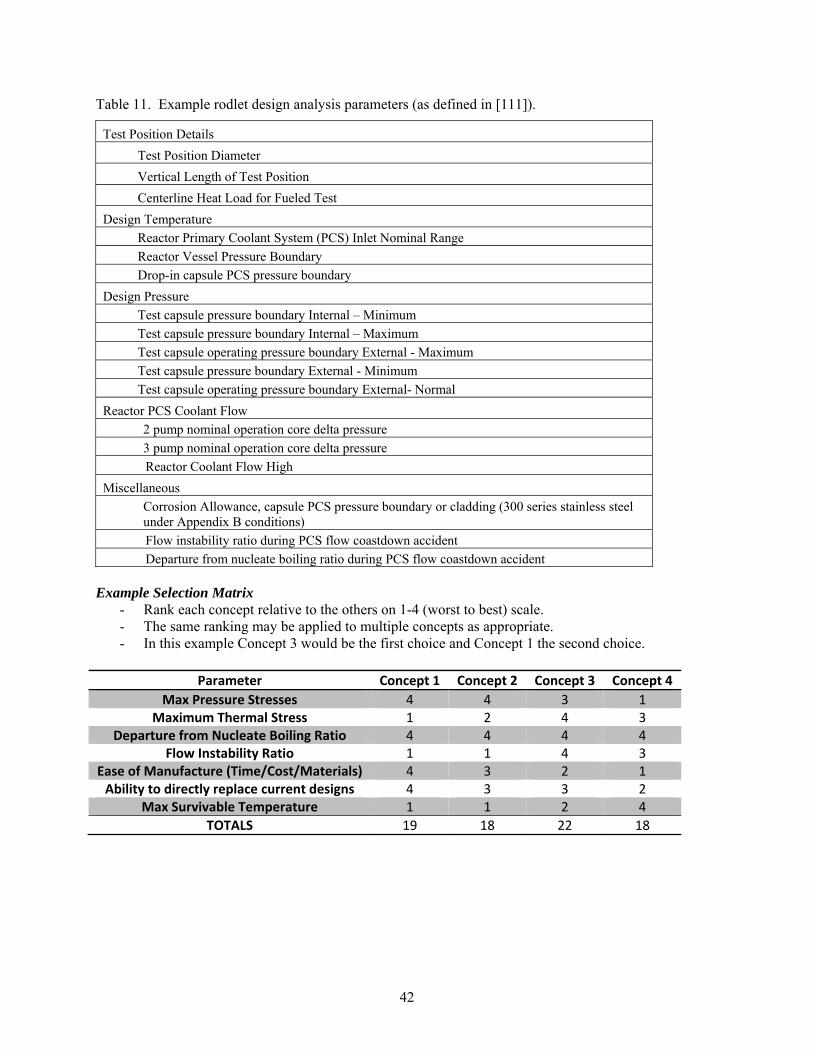
42
Table 11. Example rodlet design analysis parameters (as defined in [111]).
Test Position Details
Test Position Diameter
Vertical Length of Test Position
Centerline Heat Load for Fueled Test
Design Temperature
Reactor Primary Coolant System (PCS) Inlet Nominal Range
Reactor Vessel Pressure Boundary
Drop-in capsule PCS pressure boundary
Design Pressure
Test capsule pressure boundary Internal – Minimum
Test capsule pressure boundary Internal – Maximum
Test capsule operating pressure boundary External - Maximum
Test capsule pressure boundary External - Minimum
Test capsule operating pressure boundary External- Normal
Reactor PCS Coolant Flow
2 pump nominal operation core delta pressure
3 pump nominal operation core delta pressure
Reactor Coolant Flow High
Miscellaneous
Corrosion Allowance, capsule PCS pressure boundary or cladding (300 series stainless steel under Appendix B conditions)
Flow instability ratio during PCS flow coastdown accident
Departure from nucleate boiling ratio during PCS flow coastdown accident
Example Selection Matrix - Rank each concept relative to the others on 1-4 (worst to best) scale. - The same ranking may be applied to multiple concepts as appropriate. - In this example Concept 3 would be the first choice and Concept 1 the second choice.
Parameter Concept 1 Concept 2 Concept 3 Concept 4
Max Pressure Stresses 4 4 3 1 Maximum Thermal Stress 1 2 4 3
Departure from Nucleate Boiling Ratio 4 4 4 4 Flow Instability Ratio 1 1 4 3
Ease of Manufacture (Time/Cost/Materials) 4 3 2 1 Ability to directly replace current designs 4 3 3 2
Max Survivable Temperature 1 1 2 4
TOTALS 19 18 22 18

43
2.3 Technology Demonstrations
Top-ranking conceptual clad system designs from the Phase I Ranked Technologies list will be evolved into engineering designs for lab scale test rodlets, which will then be fabricated for further testing under the Technology Demonstration work element. The number of cladding designs selected for demonstration testing will be dependent on performance of the various materials in the technology development testing (e.g. it is currently unclear how many materials / designs will meet the feasibility requirements necessary to reach the Phase I Technologies list) and the level of funding available. Fabricated rodlets will maintain the same radial dimensions as full-scale fuel rods, but will be produced in shorter lengths (~15-45 cm) to reduce material requirements and to simplify irradiation testing.
Each fabricated rodlet undergo full cold (nonnuclear) characterization in the correct fabricated geometry (unfueled) in advance of performing nuclear (in-pile) irradiation tests. A series of unfueled characterization and irradiation tests will be performed in advance of testing fueled rodlets. The primary distinction between testing performed in the Technology Demonstration work element relative to the previous Technology Development testing is that the previous work focused on basic materials characterization on small scale samples (coupons, partial length cylinders, etc.) while demonstration tests will be performed on cladding rodlets. Cold characterization and nonnuclear testing of the rodlet prototypes will provide baseline measurements for comparison to PIE results. It is anticipated that this work element, which will carry a reduced number (one or two) technologies, will take approximately three to five years to complete.
2.3.1 Rodlet Engineering Design
Conceptual rodlets, derived from the full length fuel rod design, should be designed to ensure that they can eventually be demonstrated in a test reactor; therefore, the material properties and dimensional parameters must meet test reactor requirements, restrictions, and dimensional limitations for an irradiation position that meets the test needs (e.g. based on neutron spectrum, fluence rate, temperature, pressure, etc.). Before developing a conceptual test rodlet design, the LWRS lead researchers should request a listing of available positions for each test reactor of interest from the associated Experiment Manager (EM) or Project Manager who will identify an available irradiation location where the experiment might be placed and the reactor cycle(s)/conditions during which the experiment would be irradiated. Once the test reactor facility and specific irradiation position is determined, the test facility project team, in conjunction with the LWRS team, will compile a detailed list of requirements, including capsule dimensions, expected flux and fluence, and safety limits. These requirements will be formally documented, in the experiment Technical and Functional Requirements (T&FRs) and Project Execution Plan (PEP), in accordance with test facility design control processes. Irradiation location and cycle determination in turn defines the capsule/rodlet and basket (holder) that will comprise the complete experiment assembly. The test facility project team must formally document all relevant requirements ranging from capsule inside dimensions to temperature and pressure limitations and communicate these in writing to the LWRS design team who will then proceed with detailed test specimen design based on this information.
Once a test reactor position has been identified for irradiation of a specific experiment, the irradiation capsule and/or rodlet will be designed. Test material property restrictions and descriptions that need to be considered when designing an experiment assembly to be irradiated in a test reactor include:
Prohibited materials Unknown materials Explosive materials Cryogenic liquids
44
Chemical composition must be described in terms of chemical element or compound, tolerances on respective proportions, and allowable levels of trace contaminants.
Physical characteristics such as crystal structure, porosity, friability, malleabilitiy, compressibility, tensile strength, and thermal properties need to be identified.
Restricted materials Radiologically hazardous activation products, if post irradiation handling cannot be
performed within facility and personnel safety limits. Radiation sensitive materials, if the radiation effects result in a challenge to the facility safety
basis (such as a structural deformation leading to a capsule failure). Highly flammable or toxic materials, per se or as by-products of radiation sensitive materials. Reactive materials which are defined as any solid or liquid which has a reactivity index of 2
in National Fire Protection Association Publication 704 (NFPA 2001) or has a disaster or fire hazard indicating detrimental reactions in water or steam.
Experiment containment Materials that are incompatible with the test reactor fuel element cladding, the reactor
primary coolant, canal water coolant, or with the reactor PCS structural materials must be contained to ensure they are not released to the PCS or canal.
Incompatible materials (e.g. mercury, gold, copper, silver and chlorides for the INL ATR) must be secured to minimize the likelihood of being released into the reactor PCS.
The LWRS lead design engineer will contact the test reactor configuration management coordinator to provide information for cycle reference documents. Design reviews for test rodlets fabricated under work element 3.0 will be performed at 30% (conceptual), 60% (preliminary), and 90% (final) completion of the design phase. A qualified peer will technically check any document or drawing that is relied upon for design, construction, or operation. If a document or drawing is revised, (e.g., a drawing is changed as a result of a design review comment), it must once again be technically checked by a qualified peer.
Consistency in production quality and tolerances is critical to obtaining representative experimental results from which reliable conclusions can be drawn. The test reactor QA requirements and procedures will govern work at the test facility and all nuclear facilities used in development testing. The LWRS Experiment Manager will work with the researchers to ensure that work performed will meet the necessary QA requirements, or will arrange for test facility operations staff to perform the work. Program participants shall follow the requirements provided in the LWRS QAPD [19]. Some participants may not have a QA program or be able to meet QA requirements for fabrication. The LWRS Program will allow use of these participants by accepting the materials through inspection and analysis and/or source inspection or a combination. Typically, a quality plan specific to each experiment project will be included in the Project Execution Plan, written during the first stage of work. All materials, parts, and components will undergo receipt inspection and analysis by a quality engineer, and any nonconformances must be resolved before test development can proceed. Archiving and retrieval of records and data are broken into two major groups: the operating data and the test results data. Specification of which data to archive, in what medium, and for how long will be determined by the researcher and documented in the experiment Quality Program Plan.
2.3.2 Rodlet Fabrication
Once the rodlet parameters have been determined, fabrication must conform to those parameters. Manufacturing tolerances are necessarily tight, such that test specimens will fit in the specified test position and will conform to the specifications used to perform the neutronic and thermal analyses of the experiment assembly as a whole. After fabrication, the exact chemical composition of the as-built
45
experiment assembly must be determined within allowable uncertainties using appropriate and certified analytical chemistry methods.
Fabrication of experiment specimens that support both baseline cold characterization and irradiation demonstrations may occur in radiological facilities, nuclear facilities, or machine shops at DOE laboratories, private vendors, and/or universities depending on the individual experiment objectives, design, and facility capabilities/resources. Initially, LWRS experiment cladding rodlets (and potentially fuel specimens) may be fabricated by external vendors and supplied to the designated laboratory performing the work. As test facilities acquire the capability to perform the work, the fuel cladding systems may be fabricated at that facility. Material certifications, fabrication records, weld records, and inspection/QA records shall be required from all vendors/laboratories to include in an experiment As-Built Data Package. All measurement and test equipment will be calibrated and calibration records must be controlled. Materials used in test specimen fabrication will be quality controlled and stored in controlled storage when not in process. As-Built Data Package checklists should be used to ensure that all relevant information is included for acceptance at the test facility. Appendix D includes an example As-Built Data Package checklist and an example fabrication process work sheet that can be used by principal investigators (and vendors/subcontractors) as they are supervising fabrication activities.
Technical and functional requirements (T&FRs) will be written by the principal investigators and/or program leads to clearly identify fabrication requirements for each technology being tested to meet test facility safety, quality, and program requirements. The T&FRs will include fabrication codes and standards, cleanliness standards, design analysis requirements, test requirements, and inspection criteria. Technical and functional requirements for fabrication by vendors, universities or subcontractors will be included in the contract Statement of Work (SOW). Fabrication plans will be written by the principal investigators and design engineers, with acceptance by the program Quality Engineer, to clearly define fabrication specifications, critical attributes, and fabrication methodologies. Design drawings will include all applicable ASTM standards/codes for fabrication and inspection. Inspection plans will be written by the principal investigators and the design engineers, with acceptance by the program Quality Engineer, to clearly define all inspection criteria, inspection checklists, and verification/acceptance certifications (for work at INL, this is explicitly stated in [112]; other test facilities will have similar facility-specific requirements).
2.3.2.1 Quality Requirements
All participants shall comply with the applicable requirements of the LWRS Program Quality Assurance Program Document (INL/MIS-10-19844) using their existing QA programs. The QA program of the LWRS Program is based on the requirements defined in American Society of Mechanical Engineers (ASME) NQA-1-2008, 1a-2009, “Quality Assurance Requirements for Nuclear Facility Applications” [19].
All experiment components to be used in technology demonstrations shall be designed, fabricated, and analyzed per NQA-1 standards. Participants are not required to have in place or establish an NQA-1 compliant program in order to meet the requirements of the LWRS Quality Assurance Program [19]. However, participants must be able to demonstrate how the specified NQA-1 requirements selected in the work packages are implemented through the use of their existing QA programs. Universities performing LWRS Program work as a subcontractor to a national laboratory shall follow the requirements of the LWRS QAPD as flowed down through contractual documents.
LWRS Program work scope or program activities progressing beyond the quality requirements identified in Section 4 shall comply with the applicable requirements from Parts I and II of NQA-1-2008 and 1a-2009, Addenda. Additionally, specific work being conducted with the potential for future licensing decisions shall consider the requirements of 10 CFR 50, Appendix B, “Quality Assurance Criteria for Nuclear Power Plants and Fuel Reprocessing Plants.”

46
2.3.2.2 Safety Requirements
Regardless of the facility used to fabricate, characterize and evaluate experiment components / assemblies for irradiation testing, the experiment components must be designed to meet facility limits for special nuclear materials, criticality safety, safety basis requirements, and Hazard Category (HC) limits for radiological (less than HC III) and nuclear facilities (HCIII and greater), as applicable. Program specific fabrication and characterization requirements shall be included in program specific requirements and specifications documentation [see, for example, 112].
2.3.3 Baseline Rodlet Characterization
The primary objective of cold (nonnuclear) characterization tests is to provide baseline data on the fuel cladding system design. Characterization tests will specifically focus on the physical and chemical properties of the cladding system and interactions with water and/or metals. The rodlet cold characterization data will be used to:
• Provide baseline properties prior to irradiation, and • To inform prototype testing prior to irradiation.
Prototype testing is planned to characterize performance of the cladding design in the intended cylindrical geometry in appropriate environment conditions. Prototype testing will also be used as a risk mitigation tool for irradiation readiness. Specific operational prototype tests discussed in the following sections will be used to measure rodlet corrosion under flowing water conditions, thermal cyclic behavior, bend performance, and reaction to a steam environment (simulating LOCA conditions).
The cold characterization tests are organized according to two classifications, namely “prototype” and “baseline,” as shown in Figure 13 [113]. Tests are further grouped into “non-destructive” and “destructive” activities. The example characterization test plan shown in Figure 13 was developed specifically for a candidate SiC-CMC/Zircaloy-4 hybrid cladding tube. While many of the characterization measurements or tests can be translated to alternate cladding designs (i.e. fully ceramic SiC-SiC cladding), some are specific to the hybrid design and would require replacement with the appropriate test or standard for an alternate design.
The characterization tests listed in Figure 13 will help demonstrate the following advantageous properties of the proposed designs:
High strength at temperature to help mitigate accident scenarios.
Low chemical reactivity of SiC to reduce the rapid exothermic reaction between the clad and high temperature water that generates hydrogen, relative to zirconium-based cladding.
The lower neutron cross section has the potential to improve nuclear fuel economics by reducing parasitic capture in the cladding.
Reduced embrittlement and improved radiation stability, increasing fuel lifetimes compared to zirconium.
Cladding hardness and dimensional stability, which will decrease fretting susceptibility.
A specific characterization plan will be written for each fuel cladding system technology being tested to describe the methods, data collection parameters, and uncertainties of the tasks specified for characterization activities. The characterization plan will identify specific test plans or procedures to be followed and the frequency and proposed acceptance criteria for each of the tests, with reference to ASTM standards and codes as applicable. The specific acceptance criteria for each test will be included
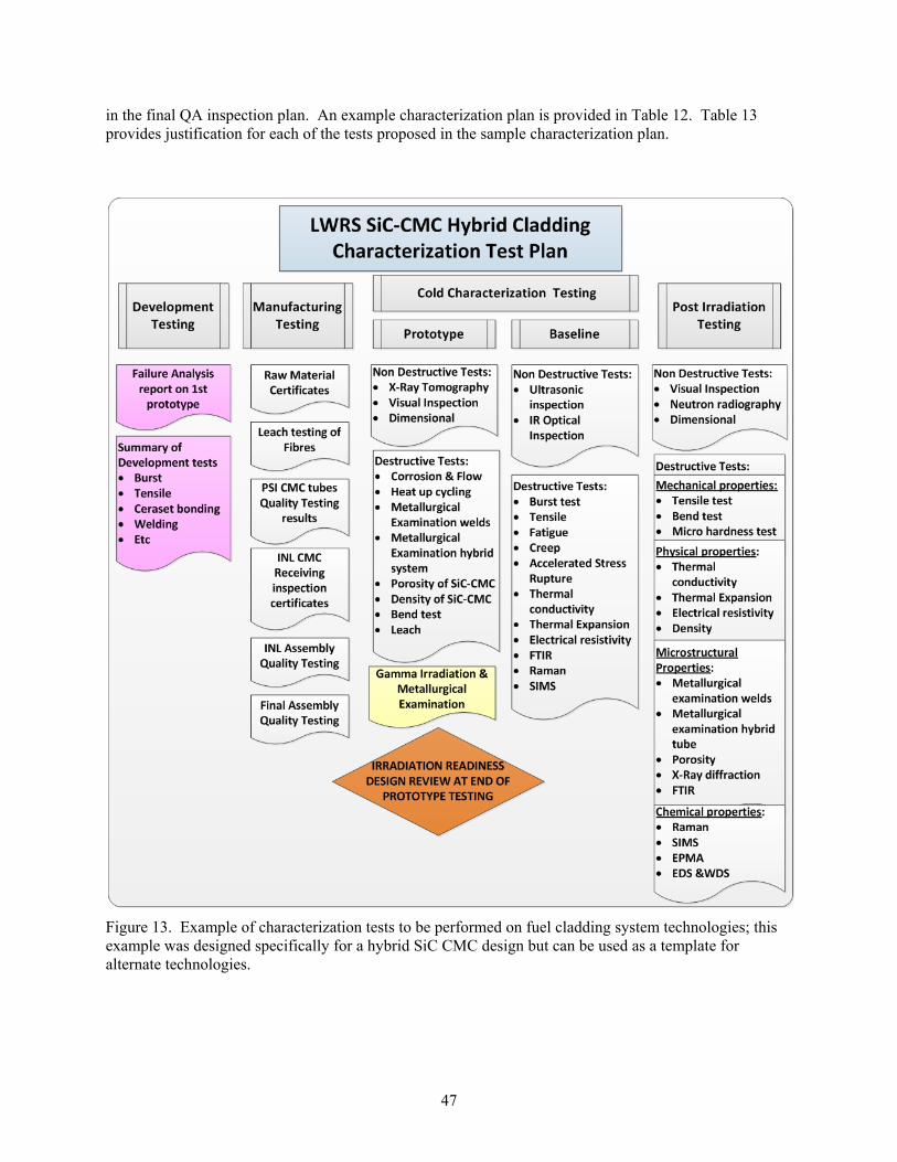
47
in the final QA inspection plan. An example characterization plan is provided in Table 12. Table 13 provides justification for each of the tests proposed in the sample characterization plan.
Figure 13. Example of characterization tests to be performed on fuel cladding system technologies; this example was designed specifically for a hybrid SiC CMC design but can be used as a template for alternate technologies.

48
Table 12. Example characterization plan for rodlet prototypes.
The collected characterization data will be integrated to make a comparison between conventional LWR cladding, alternative cladding designs previously tested under irradiation conditions, and cladding system technologies being demonstrated under the LWRS Program. Initial interpretation of the data will be used to provide confidence in the safe system performance during irradiation testing and to help guide the design process for follow-on prototype designs. Lessons learned during the course of testing will be used to guide the remaining characterization tests or tests of alternate cladding designs. Baseline measurements/properties will be compared to post-irradiation examination results to evaluate cladding system performance under irradiation conditions.
Not all of the testing requirements have been fully developed or quantified at this time. In all practical cases, the tests will be compared with standard Zircaloy cladding. Many of the proposed tests have been developed specifically for testing advanced, ceramic-based cladding systems and are adapted from standard test procedures.
Type of Test Test Samples:
Prototype
Test Samples: Zr-4
(baseline)
Testing Procedure
Gamma Irradiation Gamma Irradiation & Metallurgical Examination
1 Mock-up and several test pieces 1
PLN-3963
Non-Destructive Testing
X-Ray Tomography All experiment assemblies (10)
PLN-3950
Visual Inspection All experiment assemblies (10)
PLN-3961
Dimensional All experiment assemblies (10)
PLN-3961
Destructive Testing
Flow/Corrosion
No 1 & 2 experiment assemblies 1
PLN-3951
Thermal Cyclic Test No 3 experiment
assembly 1 PLN-3958
Metallurgical Examination of Welds No 4 experiment assembly welds
PLN-3964
Metallurgical Examination No 4 experiment
assembly PLN-3964
Density/Porosity No 4 SiC-CMC
tubing PLN-3957 PLN-3956
Bend Test No 5 experiment
assembly 1 PLN-3959
Leach Tests No 4 SiC/CMC processed tubing
PLN-3960
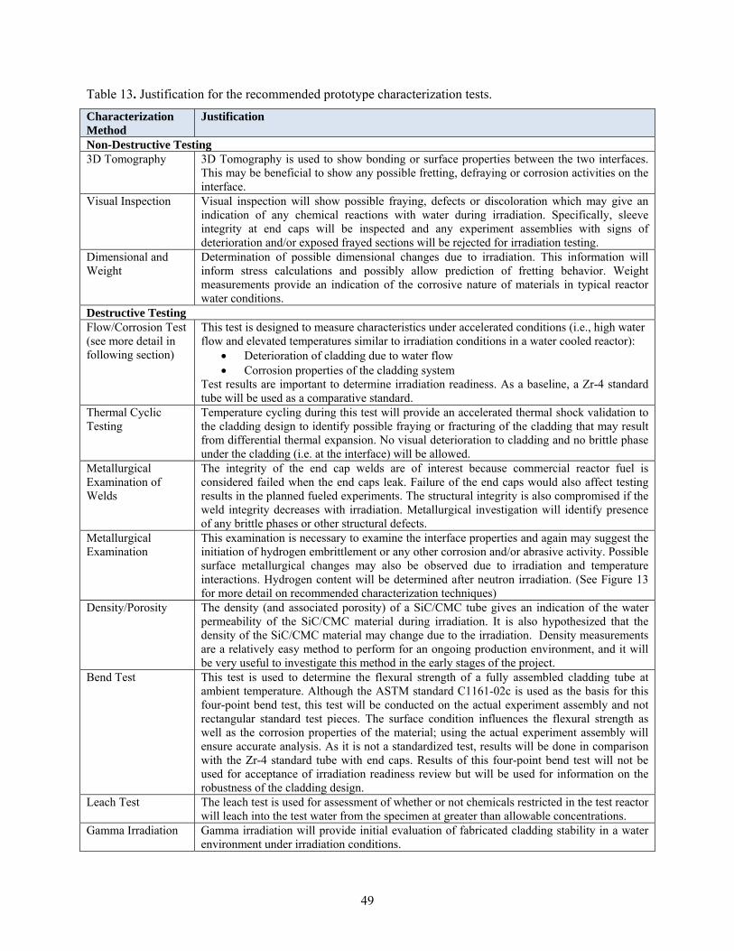
49
Table 13. Justification for the recommended prototype characterization tests.
Characterization Method
Justification
Non-Destructive Testing 3D Tomography 3D Tomography is used to show bonding or surface properties between the two interfaces.
This may be beneficial to show any possible fretting, defraying or corrosion activities on the interface.
Visual Inspection Visual inspection will show possible fraying, defects or discoloration which may give an indication of any chemical reactions with water during irradiation. Specifically, sleeve integrity at end caps will be inspected and any experiment assemblies with signs of deterioration and/or exposed frayed sections will be rejected for irradiation testing.
Dimensional and Weight
Determination of possible dimensional changes due to irradiation. This information will inform stress calculations and possibly allow prediction of fretting behavior. Weight measurements provide an indication of the corrosive nature of materials in typical reactor water conditions.
Destructive Testing Flow/Corrosion Test (see more detail in following section)
This test is designed to measure characteristics under accelerated conditions (i.e., high water flow and elevated temperatures similar to irradiation conditions in a water cooled reactor):
Deterioration of cladding due to water flow Corrosion properties of the cladding system
Test results are important to determine irradiation readiness. As a baseline, a Zr-4 standard tube will be used as a comparative standard.
Thermal Cyclic Testing
Temperature cycling during this test will provide an accelerated thermal shock validation to the cladding design to identify possible fraying or fracturing of the cladding that may result from differential thermal expansion. No visual deterioration to cladding and no brittle phase under the cladding (i.e. at the interface) will be allowed.
Metallurgical Examination of Welds
The integrity of the end cap welds are of interest because commercial reactor fuel is considered failed when the end caps leak. Failure of the end caps would also affect testing results in the planned fueled experiments. The structural integrity is also compromised if the weld integrity decreases with irradiation. Metallurgical investigation will identify presence of any brittle phases or other structural defects.
Metallurgical Examination
This examination is necessary to examine the interface properties and again may suggest the initiation of hydrogen embrittlement or any other corrosion and/or abrasive activity. Possible surface metallurgical changes may also be observed due to irradiation and temperature interactions. Hydrogen content will be determined after neutron irradiation. (See Figure 13 for more detail on recommended characterization techniques)
Density/Porosity The density (and associated porosity) of a SiC/CMC tube gives an indication of the water permeability of the SiC/CMC material during irradiation. It is also hypothesized that the density of the SiC/CMC material may change due to the irradiation. Density measurements are a relatively easy method to perform for an ongoing production environment, and it will be very useful to investigate this method in the early stages of the project.
Bend Test This test is used to determine the flexural strength of a fully assembled cladding tube at ambient temperature. Although the ASTM standard C1161-02c is used as the basis for this four-point bend test, this test will be conducted on the actual experiment assembly and not rectangular standard test pieces. The surface condition influences the flexural strength as well as the corrosion properties of the material; using the actual experiment assembly will ensure accurate analysis. As it is not a standardized test, results will be done in comparison with the Zr-4 standard tube with end caps. Results of this four-point bend test will not be used for acceptance of irradiation readiness review but will be used for information on the robustness of the cladding design.
Leach Test The leach test is used for assessment of whether or not chemicals restricted in the test reactor will leach into the test water from the specimen at greater than allowable concentrations.
Gamma Irradiation Gamma irradiation will provide initial evaluation of fabricated cladding stability in a water environment under irradiation conditions.
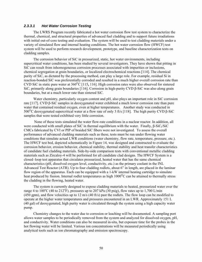
50
2.3.3.1 Hot Water Corrosion Testing
The LWRS Program recently fabricated a hot water corrosion flow test system to characterize the thermal, chemical, and structural properties of advanced fuel cladding and to support future irradiations with initial out-of-core testing and evaluation. The system will be used to test cladding materials under a variety of simulated flow and internal heating conditions. The hot water corrosion flow (HWCF) test system will be used to perform research development, prototype, and baseline characterization tests on cladding samples.
The corrosion behavior of SiC in pressurized, static, hot water environments, including supercritical water conditions, has been studied by several investigators. They have shown that pitting in SiC can result from inhomogeneous corrosion processes associated with impurities or inclusions, chemical segregation at grain boundaries, or localized electrochemical reactions [114]. The chemical purity of SiC, as dictated by the processing method, can play a large role. For example, residual Si in reaction-bonded SiC was preferentially corroded and resulted in a much higher overall corrosion rate than CVD SiC in static pure water at 360OC [115, 116]. High corrosion rates were also observed for sintered SiC, primarily along grain boundaries [116]. Corrosion in high-purity CVD β-SiC was also along grain boundaries, but at a much lower rate than sintered SiC.
Water chemistry, particularly oxygen content and pH, also plays an important role in SiC corrosion rate [117]. CVD β-SiC samples in deoxygenated water exhibited a much lower corrosion rate than pure water that contained residual oxygen, even at higher temperatures. Another study was conducted in 500OC deoxygenated supercritical water at a flow rate of only 3 ft/s [118]. The high purity CVD β-SiC samples that were tested exhibited very little corrosion.
None of these tests simulated the water flow-rate conditions in a nuclear reactor. In addition, all were conducted with small plates of SiC in thermal equilibrium with the water. Finally, β-SiCf/SiC CMCs fabricated by CVI or PIP of braided SiC fibers were not investigated. To assess the overall performance of advanced cladding materials such as these, tests must be run under flowing water conditions that simulate actual LWR conditions (water chemistry, flow rate, temperature, pressure, etc.). The HWCF test bed, depicted schematically in Figure 14, was designed and constructed to evaluate the corrosion behavior, erosion behavior, chemical stability, thermal stability and heat transfer characteristics of candidate fuel cladding materials. Side-by-side comparison tests with conventional metallic cladding materials such as Zircaloy-4 will be performed for all candidate clad designs. The HWCF System is a closed–loop test apparatus that circulates pressurized, heated water that has the same chemical characteristics (pH, dissolved oxygen level, conductivity, etc.) as the primary coolant in the INL Advanced Test Reactor (ATR). Up to four cladding rodlets, about 6” in length, are placed in the laminar flow region of the apparatus. Each can be equipped with a 1-kW internal heating cartridge to simulate heat produced by fission. Internal rodlet temperatures as high 1000OC can be attained to thermally stress the cladding in the flowing, heated water.
The system is currently designed to expose cladding materials to heated, pressurized water over the range 4 to 100oC (40 to 212oF), pressures up to 207 kPa (30 psig), flow rates up to 1,700 L/min (450 gpm), and flow velocities up to 12 m/s (40 ft/s) past the rodlets. The flow loop can be modified to operate at the higher water temperatures and pressures encountered in an LWR. Approximately 151 L (40 gal) of deoxygenated, high purity water is circulated through the system using a high capacity water pump.
Chemistry changes to the water due to corrosion or leaching will be documented. A sampling port allows water samples to be periodically removed from the system and analyzed for dissolved oxygen, pH, and conductivity. Water conditions can also be measured in-situ, but exposure time for the probes in the hot flowing water will be limited. Various ion concentrations will be measured periodically using analytical tools such as ion chromatography and emission spectroscopy.
51
The water temperature at the inlet to the rodlets is held constant using a controller coupled to a hot water immersion heater located within the 76 L (20 gal) stainless steel reservoir (Figure 14). A heat exchanger located downstream of the rodlets is used to remove excess heat from the system produced by the internal rodlet heaters.
Figure 14. 3-D drawing of the hot water corrosion flow system.
An integral thermocouple measures the inner wall temperature of each rodlet during steady-state operation while a retractable thermocouple measures the outer wall temperature of each rodlet. Temperature drop and pressure drop across the individual rodlets are recorded. These temperature gradient data will be useful during corrosion studies as well as thermal stress and heat transfer analysis studies. These data will allow heat flux measurements to be correlated with cladding design over a long period of time as corrosion/wear (if any) proceeds. Since heat transfer rate is known to be strongly
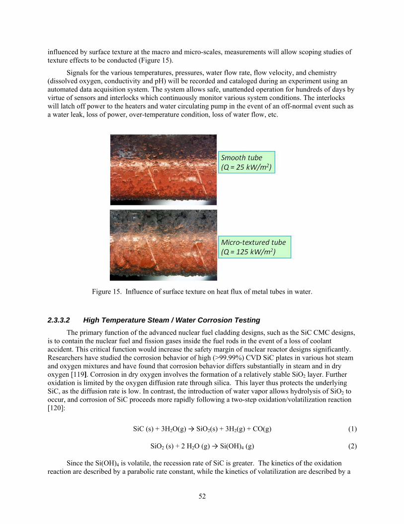
52
influenced by surface texture at the macro and micro-scales, measurements will allow scoping studies of texture effects to be conducted (Figure 15).
Signals for the various temperatures, pressures, water flow rate, flow velocity, and chemistry (dissolved oxygen, conductivity and pH) will be recorded and cataloged during an experiment using an automated data acquisition system. The system allows safe, unattended operation for hundreds of days by virtue of sensors and interlocks which continuously monitor various system conditions. The interlocks will latch off power to the heaters and water circulating pump in the event of an off-normal event such as a water leak, loss of power, over-temperature condition, loss of water flow, etc.
Figure 15. Influence of surface texture on heat flux of metal tubes in water.
2.3.3.2 High Temperature Steam / Water Corrosion Testing
The primary function of the advanced nuclear fuel cladding designs, such as the SiC CMC designs, is to contain the nuclear fuel and fission gases inside the fuel rods in the event of a loss of coolant accident. This critical function would increase the safety margin of nuclear reactor designs significantly. Researchers have studied the corrosion behavior of high (>99.99%) CVD SiC plates in various hot steam and oxygen mixtures and have found that corrosion behavior differs substantially in steam and in dry oxygen [119]. Corrosion in dry oxygen involves the formation of a relatively stable SiO2 layer. Further oxidation is limited by the oxygen diffusion rate through silica. This layer thus protects the underlying SiC, as the diffusion rate is low. In contrast, the introduction of water vapor allows hydrolysis of SiO2 to occur, and corrosion of SiC proceeds more rapidly following a two-step oxidation/volatilization reaction [120]:
SiC (s) + 3H2O(g) → SiO2(s) + 3H2(g) + CO(g) (1) SiO2 (s) + 2 H2O (g) → Si(OH)4 (g) (2)
Since the Si(OH)4 is volatile, the recession rate of SiC is greater. The kinetics of the oxidation reaction are described by a parabolic rate constant, while the kinetics of volatilization are described by a
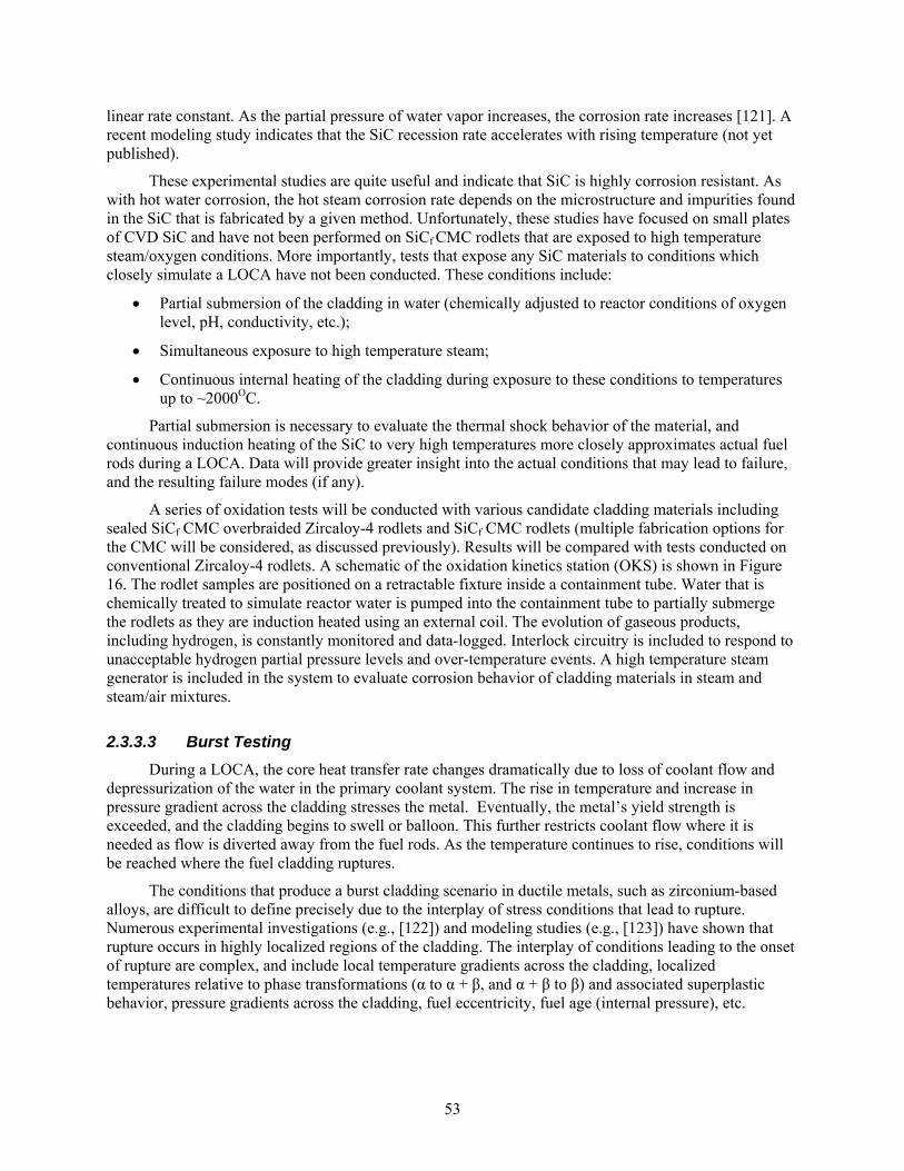
53
linear rate constant. As the partial pressure of water vapor increases, the corrosion rate increases [121]. A recent modeling study indicates that the SiC recession rate accelerates with rising temperature (not yet published).
These experimental studies are quite useful and indicate that SiC is highly corrosion resistant. As with hot water corrosion, the hot steam corrosion rate depends on the microstructure and impurities found in the SiC that is fabricated by a given method. Unfortunately, these studies have focused on small plates of CVD SiC and have not been performed on SiCf CMC rodlets that are exposed to high temperature steam/oxygen conditions. More importantly, tests that expose any SiC materials to conditions which closely simulate a LOCA have not been conducted. These conditions include:
Partial submersion of the cladding in water (chemically adjusted to reactor conditions of oxygen level, pH, conductivity, etc.);
Simultaneous exposure to high temperature steam;
Continuous internal heating of the cladding during exposure to these conditions to temperatures up to ~2000OC.
Partial submersion is necessary to evaluate the thermal shock behavior of the material, and continuous induction heating of the SiC to very high temperatures more closely approximates actual fuel rods during a LOCA. Data will provide greater insight into the actual conditions that may lead to failure, and the resulting failure modes (if any).
A series of oxidation tests will be conducted with various candidate cladding materials including sealed SiCf CMC overbraided Zircaloy-4 rodlets and SiCf CMC rodlets (multiple fabrication options for the CMC will be considered, as discussed previously). Results will be compared with tests conducted on conventional Zircaloy-4 rodlets. A schematic of the oxidation kinetics station (OKS) is shown in Figure 16. The rodlet samples are positioned on a retractable fixture inside a containment tube. Water that is chemically treated to simulate reactor water is pumped into the containment tube to partially submerge the rodlets as they are induction heated using an external coil. The evolution of gaseous products, including hydrogen, is constantly monitored and data-logged. Interlock circuitry is included to respond to unacceptable hydrogen partial pressure levels and over-temperature events. A high temperature steam generator is included in the system to evaluate corrosion behavior of cladding materials in steam and steam/air mixtures.
2.3.3.3 Burst Testing
During a LOCA, the core heat transfer rate changes dramatically due to loss of coolant flow and depressurization of the water in the primary coolant system. The rise in temperature and increase in pressure gradient across the cladding stresses the metal. Eventually, the metal’s yield strength is exceeded, and the cladding begins to swell or balloon. This further restricts coolant flow where it is needed as flow is diverted away from the fuel rods. As the temperature continues to rise, conditions will be reached where the fuel cladding ruptures.
The conditions that produce a burst cladding scenario in ductile metals, such as zirconium-based alloys, are difficult to define precisely due to the interplay of stress conditions that lead to rupture. Numerous experimental investigations (e.g., [122]) and modeling studies (e.g., [123]) have shown that rupture occurs in highly localized regions of the cladding. The interplay of conditions leading to the onset of rupture are complex, and include local temperature gradients across the cladding, localized temperatures relative to phase transformations (α to α + β, and α + β to β) and associated superplastic behavior, pressure gradients across the cladding, fuel eccentricity, fuel age (internal pressure), etc.
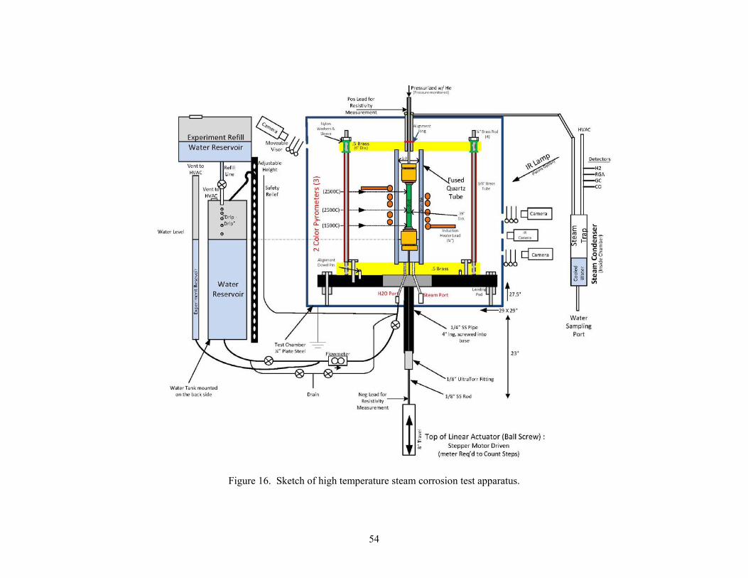
54
Figure 16. Sketch of high temperature steam corrosion test apparatus.
55
The oxidation kinetics station (Figure 16) will be used to contrast swelling/ballooning/rupture conditions of (unirradiated) all-metal cladding, with cladding that incorporates SiCf CMC structures. Rodlet samples of conventional zirconium metal cladding alloys (e.g., Zircaloy-2 and Zircaloy-4) and their SiCf CMC counterparts will be thermally cycled in a steam environment to evaluate rupture behavior in conditions simulating a LOCA. Parametric studies will be conducted in which rodlets, pressurized with He, are heated in a steam or steam/water environment. The onset of swelling/ballooning in all-metal cladding will be accompanied by a gradual pressure drop within the rodlet as the tube volume increases. A sudden pressure drop, and release of He, will be recorded when a rupture scenario occurs.
Preliminary burst testing will be conducted at room temperature using a uniaxial press coupled to a load cell. Powder-packed all-metal rodlets and candidate advanced rodlet designs will be pressurized until swelling or rupture occurs. Preliminary tests conducted at the Halden Reactor Project (HRP) using a drop-weight apparatus indicated that SiCf CMC over-braided Zircaloy-4 rodlet samples (hybrid cladding design) resisted expansion up to the test limit conditions of the apparatus, ~67 ksi (460 MPa) internal pressure. In contrast, unreinforced Zircaloy-4 rodlets exhibited about 9.5% strain at 63.5 ksi (437 MPa) (Figure 17).
Figure 17. Halden burst-strain test of Zircaloy-4 tubes using a drop-weight apparatus, (a) 9.5% strain in an all-metal rodlet sample at 437 MPa (left) and (b) a Zircaloy-4 tube over-braided with SiCf CMC resisted strain up to the test limit of 460 MPa.
2.3.4 Irradiation Testing
The advanced nuclear material and nuclear fuel design development requires an extended test and evaluation program. Nuclear fuel systems must perform reliably under all operating conditions in the complex nuclear reactor environment. Nuclear reactors create a very harsh environment for engineered materials. Currently operating commercial reactors utilize hot water as a coolant and moderator. The water creates corrosion throughout the nuclear power plant including the nuclear fuel. The corrosion products can deposit on the cladding, creating a complex physical, chemical and thermal environment. Due to the many fission products, the nuclear fuel contained by the cladding creates a unique chemical environment. The presence of neutrons and gamma-rays tends to break down and damage materials throughout reactor operation. The fuel cladding system must survive rapid thermal and pressure transients, long term repeated stresses, thermal cycling and changing heat transfer conditions. In-reactor testing is the primary mechanism available to evaluate the performance of advanced fuel cladding systems. Irradiation testing of both unfueled and fueled rodlets will be conducted to demonstrate technology performance to characterize the cladding/water/radiation interactions in the proposed
56
advanced cladding designs. The use of successively complex experiments will demonstrate steady-state, transient, accident, and failure behavior of the advanced fuel pin design. These tests will provide operational data necessary to define the licensing basis for advanced fuel cladding systems.
2.3.4.1 Definition of In-Pile Testing Requirements
Prior to selecting an appropriate test reactor facility for rodlet irradiation, the desired test conditions must be fully defined with input requested from the identified stakeholders. Required parameters include:
Neutron fluence rate and energy spectrum
Coolant conditions, including temperature, pressure, flow rate and chemistry
Linear heat rate
Total neutron fluence and target exposure
Other parameters will be defined during the technology definition stage of the program (section 2.1.2).
The specific test reactor and experiment location will be selected such that the test reactor power in the vicinity of the experiment is similar to existing light water reactors (approximately1014n/cm2/s neutron flux) with a target exposure of 60,000 to 80,000 MWd/Mt (based on a 235U enrichment of 5-8%). A typical PWR operates with average Linear Heat Generation Rate (LHGR) of 17.5 kW/m (maximum 41 kW/m); average LHGR in a BWR is approximately 20 kW/m (44 kW/m maximum). Previous LWR experiments conducted at the INL established a LHGR of 39.4 kW/m (12 kW/ft) as an experiment bounding condition [124].
Where possible, rodlets intended for in-pile testing should be designed to take advantage of existing analyses, designs and structures developed for previous experiments at the selected test reactor. For example, the rodlet design developed for testing hybrid SiC-CMC / Zircaloy-4 rodlets at the INL Advanced Test Reactor [125] were designed to take advantage of the previous analysis, designs and structures created for MOX fuel and LWR experiments previously conducted at the ATR. The effective reactivity and heat transfer and source term bound the LWRS rodlet samples [126]. Limiting the design to the ATR MOX/LWR rodlet model allows a faster start to the irradiation campaign. The same approach can be applied to any of the test facilities considered for the LWRS irradiation demonstrations. Once the capsule design matures, the rod length and specific features will tend to be more representative of commercial products.
2.3.4.2 Types of Demonstrations
A significant effort will be applied to optimizing the technology demonstration activities to take the greatest advantage of each test reactor and its capabilities. The testing program will allow evaluation of multiple aspects of fuel cladding system performance including nuclear, mechanical and thermal performance. Iteration of the cladding design and demonstrated cladding behavior will allow prediction of system behavior during steady-state, transient operation and severe event transients. The evaluation of the on-going fuel cladding system performance expectations will be measured against the licensing basis requirements and potential benefits to the entire core and reactor system. The goal is to create the basic data required for a licensing submittal and industrial confidence in the new technology and its application to existing nuclear power plants.
The use of successively complex irradiation experiments will demonstrate steady-state, transient, accident, and failure behavior of nuclear fuel. Ultimately, the intent is to ramp the fuel up and down in power to simulate the duty cycle observed in commercial reactors. The transient testing will provide more
57
information on pellet / cladding interactions. Performance at higher exposures will also be tested. The final round of irradiation testing will include severe power ramps. Rapid power ramps are encountered during accident scenarios at commercial reactors. Demonstration of predictable acceptable results from severe duty testing will ensure the licensing basis is well understood and documented. Follow-on tests performed before reaching commercial deployment may center on temperature profiles and fabrication quality.
The irradiation demonstrations of advanced fuel cladding system designs will center on design of static “drop-in capsule” tests of the sealed cladding tube “rodlets” and instrumented lead test assemblies, but will ultimately include loop testing as the program matures. Initial rodlet tests will be unfueled, following by rodlet tests that include commercial grade UO2 fuel pellets. The increasing complexity of the experimental design will build on previous results and evolve for improving performance.
2.3.4.2.1 Steady-State Irradiation Testing
The primary purpose of steady-state testing of the advanced nuclear fuel cladding systems is to demonstrate the practical performance of the combined nuclear fuel system. The radiation and thermally induced swelling, accelerated by the nuclear fuel induced radiation field and temperatures, will demonstrate the acceptability of the experimental cladding systems. The observed performance will help provide benchmarking results for performance estimates. The testing will also demonstrate the fully integrated performance previously estimated in out-of-pile testing and unfueled rodlet irradiation. The baseline steady-state irradiations are the starting point for introducing more sophisticated and realistic design options.
During steady-state testing, the changes occurring on the surface of the cladding created by oxygen in the test water will be evaluated. The surface effects have the potential to interact farther into the cladding. The axial change in material properties will be observed. These measurements will allow benchmarking of the chemistry calculations performed. The results are expected to differ from the out-of-pile testing due to irradiation-induced effects. The entire system is expected to show increased chemical interaction with the coolant due to the radiation. A similar review of the changes induced by flow vibration will be evaluated. The presence of smaller scale flow induced corrosion will be evaluated.
A critical issue to be evaluated and benchmarked is the interaction between the pellet and cladding with increasing exposure. In conventional Zircaloy cladding the cladding tube can creep. The creep allows the pellet – clad gap to close, improving heat transfer. The metallic cladding can also strain with rapid swelling of the fuel with temperature increases. These properties will not exist in ceramic-based cladding systems where the clad swelling and creep are minimal relative to metallic cladding. This difference in behavior may require a large pellet – clad gap to accommodate fuel swelling. The large potential gap reduces uranium loading which reduces the fuel cycle economics. The large gap would also reduce heat transfer, increasing the centerline temperature of the nuclear fuel pellet. The effect of each of these design selections on fuel economics and safety margins must be considered in the design optimization. Measured irradiation data will be used to further enhance the fuel performance models discussed in section 2.2.4. Iterative measurements and modeling activities will be employed to optimize the cladding design in advance of the technology deployment phase of work.
2.3.4.2.2 Transient Testing
Nuclear fuel must operate over a number of time scales from a few microseconds up to months at a time. Operating a reactor requires operational changes to safely manage the reactor core. The planned or expected changes in operating conditions are referred to as transient core changes. Significant power, chemistry or pressure changes are performed over different operating regimes. Multiple changes must occur to reach full operating power. Conversely, the core will require power reductions over time to
58
account for operating conditions. Beyond planned power evolutions, changes in power level, pressure or chemistry may occur, creating enforced power changes.
Operating transients can place significant stress on nuclear fuel as power levels change, fuel swells and pressure inside the fuel pins increases. Operating transients in a commercial reactor can create conditions that will exceed the performance limits of the nuclear fuel, which can be observed as immediate or delayed cladding failures or untenable long term power conditions. Simulation of these transient conditions in rodlet testing will characterize nuclear fuel and cladding interaction under these conditions. Carefully controlled power ramps in the selected test reactor can be used to demonstrate expected cladding performance and benchmark calculated predictions. Measurements evaluated in post-irradiation examinations will help establish the necessary pellet – clad gap in fabricated fuel rods. Results will also help define maximum linear heat generation limits and allowable changes. The transient test matrix will include variation of the maximum temperature and power levels to determine the practical limits of the fuel in the proposed advanced cladding design.
Performance of transient tests that apply repeated stress will help populate the technology database for each demonstrated cladding option. The long term changes introduced by repeated operational power ramps will need to be well understood before the fuel cladding system is considered for use in a commercial reactor. In-pile demonstration of the cladding design will provide benchmark data for the computational fuel performance models and allow a correlation between out-of-pile and in-pile performance. Transient testing results will also provide data and confidence in predictions to make planning for accident scenario testing possible.
2.3.4.2.3 Accident Scenario Testing
Demonstration of nuclear fuel performance during postulated accident scenarios is the maximum performance test for nuclear fuel rods. The need to understand and predict the limits of fuel performance will allow safety limits to be directly defined and reactor operation bounded. The ability to predict ultimate performance of the fuel cladding system will also allow definition of licensing limits. Measured performance data will allow for assessment of the computational model accuracy, such that the fuel performance models can be used to reliably predict fuel performance under alternate accident scenarios.
Accident scenario test matrix will encompass a combination of loss of cooling, reactivity insertion and power transients. These tests will define the maximum change in internal pressure, nuclear induced strain, thermally induced stress and rapid local changes in chemical potential. The interaction of nuclear fuel and cladding will be maximized. The potential for significant pellet – clad interaction will be demonstrated. Extension to higher exposures and complex power ramps and chemistry will be evaluated.
It is expected that failure mode for advanced ceramic-based nuclear fuel cladding (or other advanced cladding technologies) under accident conditions will differ from those observed for standard zirconium-based cladding because of the high cladding strength at high temperature and low chemical reactivity. The exact mode of cladding failure will be established computationally and through out-of-pile testing.
2.3.4.3 Potential Test Facilities
The LWRS Program will utilize multiple irradiation facilities to provide the optimum irradiation service. Selection of the facilities will be based on capabilities, demonstration schedule, cost and available resources. Four test reactors have been identified as potential candidates for technology demonstrations, each of which provides unique opportunities for irradiation testing: the Idaho National Laboratory (INL) Advanced Test Reactor (ATR); the Oak Ridge National Laboratory (ORNL) High Flux Isotope Reactor (HFIR); the Halden Reactor Project (HRP) test reactor; and the Massachusetts Institute of Technology (MIT) Research Reactor (MITRR). Additional details on each of these test facilities are provided in Appendix B. This list of potential test facilities is not exhaustive; other test facilities will be identified and
59
evaluated for applicability to the LWRS advanced fuel testing program following development of the performance requirements for the advanced cladding designs (task 1.2), development of the technical and functional requirements for the cladding rodlets, and conceptual rodlet designs (work task 2.2). Early evaluation of test facility availability and capabilities will ensure that design work is consistent with requirements and limitations of the test facility that will be employed for rodlet demonstration.
Either the INL ATR or the ORNL HFIR can provide steady state irradiation testing. Instrumented lead and loop testing is also available at the ATR. The ATR can provide a very high neutron and gamma radiation source for testing of nuclear fuels and materials [127]. The ATR provides multiple test locations with a unique control system allowing multiple conditions to be controlled at the same time. The HFIR is a high flux reactor which can provide rapid turn-around times over a range of irradiation conditions [128]. A recent project at the HFIR has resulted in new LWR test capabilities that allow testing of advanced nuclear fuels and cladding materials under prototypic thermal spectrum reactor operating conditions (cladding and fuel temperatures, fuel average linear heat generation rates and cladding fluence) [129].
The HRP test reactor offers pressure and chemistry loops capable of simulating very rapid transient and accident conditions [130]. These test loops provide the correct environment to evaluate performance of the nuclear fuel cladding rodlets under realistic conditions. The HRP has a unique ability to monitor nuclear fuel performance during reactor operation, making Halden a world leader in on-line monitoring of test samples. In addition, the HRP has the potential to drive the experiment assemblies into failure modes required to define the outer limits of the fuel system cladding.
The Transient Reactor Test Facility (TREAT) at the INL could be considered for LWRS transient testing if it becomes available during the program implementation. The TREAT reactor is an air-cooled, thermal test reactor designed to test reactor fuels and structural materials during the extreme conditions seen during rapid power increases in a nuclear reactor. The reactor was mothballed in 1994 and is undergoing restart analysis to fill a critical testing role for the Department of Energy and commercial interests. If the reactor becomes operational in the near future, it may be considered for transient testing.
There are other reactors with similar general capabilities; however, most are less suitable due to power level, neutron flux properties, scheduling, cost, sample transport issues and post-irradiation examination capabilities. U.S. University reactors tend to be lower power and have less capable examination facilities. Foreign test reactors are generally higher cost and more difficult to schedule for timely response. A notable exception is the MIT Research Reactor (MITRR). The MITRR provides commercial reactor operating conditions in a high pressure loop [131]. The MITRR is also a member of the ATR National Scientific User Facility, increasing the facility access options and collaboration potential. Instrumented lead tests may also be conducted to monitor experiment conditions/parameters during irradiation testing.
Appendix B includes more detailed description of the test reactors currently being considered for technology demonstrations under this LWRS pathway.
2.3.5 Post-Irradiation Examination (PIE) Analysis
The primary objective of the post-irradiation examination activities is to provide performance data on the tested advanced cladding system design, specifically to characterize the cladding after irradiation to identify any changes in the physical, mechanical and chemical properties, identify possible interactions between the cladding materials and the nuclear fuel for fueled experiments, and to evaluate the corrosion susceptibility of the cladding under irradiation.
A specific PIE plan will be written for each fuel cladding system technology tested and for each reactor test facility to describe the methods, data collection parameters, and uncertainties of the tasks specified for characterization activities. The PIE plan will identify specific test plans or procedures to be
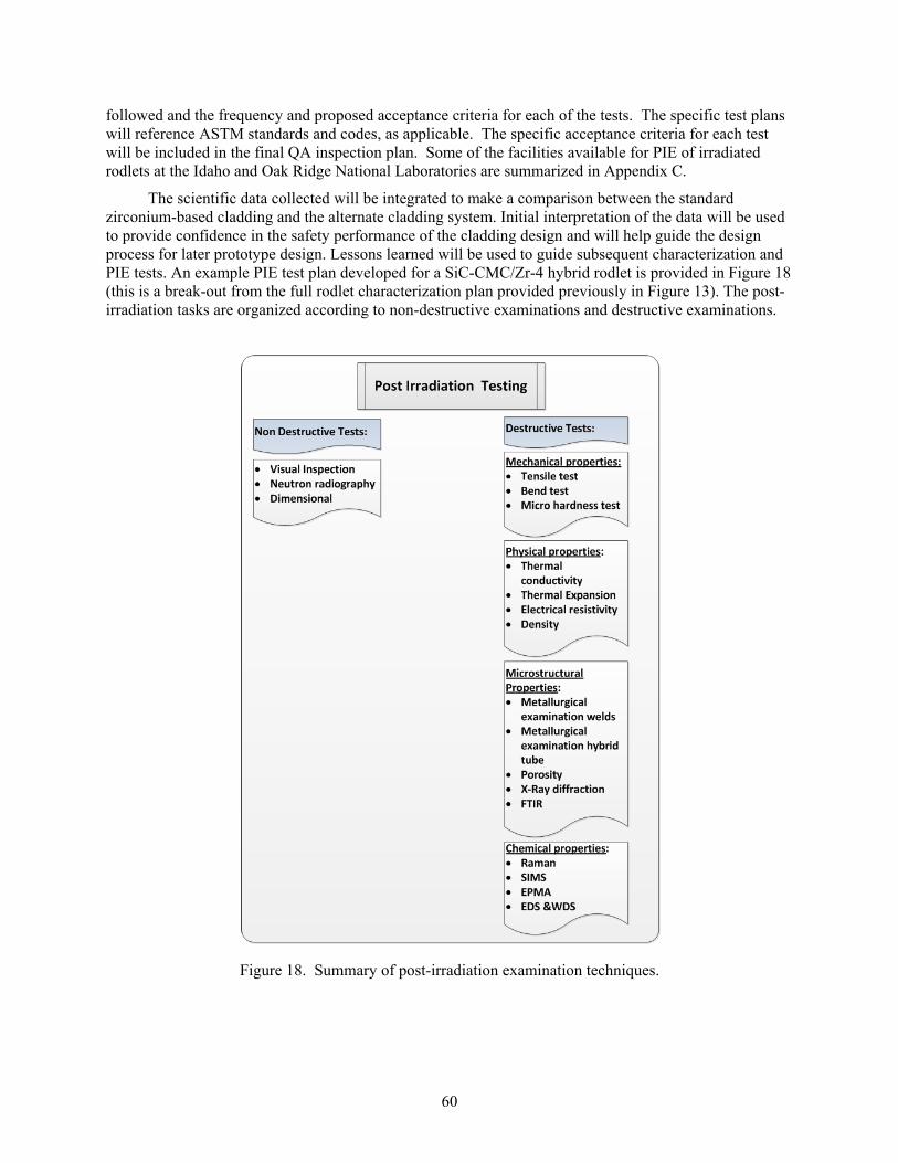
60
followed and the frequency and proposed acceptance criteria for each of the tests. The specific test plans will reference ASTM standards and codes, as applicable. The specific acceptance criteria for each test will be included in the final QA inspection plan. Some of the facilities available for PIE of irradiated rodlets at the Idaho and Oak Ridge National Laboratories are summarized in Appendix C.
The scientific data collected will be integrated to make a comparison between the standard zirconium-based cladding and the alternate cladding system. Initial interpretation of the data will be used to provide confidence in the safety performance of the cladding design and will help guide the design process for later prototype design. Lessons learned will be used to guide subsequent characterization and PIE tests. An example PIE test plan developed for a SiC-CMC/Zr-4 hybrid rodlet is provided in Figure 18 (this is a break-out from the full rodlet characterization plan provided previously in Figure 13). The post-irradiation tasks are organized according to non-destructive examinations and destructive examinations.
Figure 18. Summary of post-irradiation examination techniques.
61
2.3.1 Phase 2 Ranked Technologies
A “Phase 2” list of ranked technologies will be generated based on the materials characterization and technology demonstration test results. Similar to the “Phase 1” ranked technologies used to identify technologies recommended for rodlet demonstration, the “Phase 2” list will be developed with input from members of the technology selection committee. Top-ranking technologies at the end of the demonstration testing phase of the advanced fuel system development work will be recommended for demonstration as a lead test rod in a commercial reactor. This decision point again offers an “off-ramp” available for less promising designs. Lead test rod design and deployment will be based on the ranked technologies list, but will require partnership with commercial reactor operators, as discussed in the Technology Deployment work element (element 4.0).
2.4 Technology Deployment
The success of the LWRS Advanced LWR Nuclear Fuels Pathway will be marked by completion of a technology database for the leading advanced cladding design or designs, establishment of industry partnerships for initial technology deployment, initiation of the necessary steps for fuel qualification via industry partnerships (activity led by commercial reactor facility), and implementation of an advanced cladding design as a lead test rod in an operating commercial nuclear reactor.
2.4.1 Generate Technology Database
The Technology Database for each tested advanced cladding design will be updated throughout the fuel development program. The technology database will include all the necessary material property data and performance measurements to inform NRC licensing decisions, with the exception of performance data in an operating commercial power reactor. Key components to the technology database include:
o Mechanical properties over the operating range (nominal and off-nominal; pre- and post-irradiation)
o Thermal properties over the operating range (nominal and off-nominal; pre- and post-irradiation)
o Microstructural analysis data (pre- and post-irradiation)
o Chemical interaction data (pellet/clad and clad/coolant) over the operating range
o Corrosion behavior in flowing hot water and under steam exposure
o Irradiation stability
o Computational model simulation results and fuel performance predictions under nominal and off-nominal operating conditions
Each of the technology database elements will be archived via technical papers and internal or external reports, as appropriate. The database will also include notable conclusions or recommendations regarding each element of the cladding design, fabrication technique, or assembly (including the adopted sealing / joining technique for hermeticity).
62
2.4.2 Develop Industry Partnerships
A strong industry partnership with the LWRS Program will be required for technology deployment. Through constant interaction with stakeholders throughout the development program, including vendors and utilities, it is presumed that industry will be prepared to demonstrate the recommended technology at the end of the development phase. The government – industry partnership assumes significant cost sharing between government and industry.
2.4.3 NRC Licensing
As described in section 2.1.2.2, the fuel qualification process traditionally involves a combination of fuel design, fabrication process definition and fuel performance qualification, using in-reactor testing and performance analysis. The goal of the LWRS Advanced LWR Fuels Pathway is to generate the basic data required for a licensing submittal and industrial confidence in the new technology and its application to existing nuclear power plants. The LWRS Program will not submit the license application for the proposed advanced fuel system, but will instead provide the data necessary to support a license application to the nuclear reactor operator interested in licensing the technology for application in a specific nuclear power plant.
End of fuel cycle operations, including fuel storage and disposal plans, are a necessary component of the nuclear fuel license application. The T&FRs for the advanced fuel cladding designs must include consideration for ultimate disposal requirements, such that used fuel disposal issues will be addressed in the original design development. Advanced fuel cladding system designs should not increase the burden for used fuel disposal on the operating utilities relative to the standard zirconium-clad fuel.
2.4.4 Implement Technology
Design of a lead test rod for deployment in a commercial reactor will require refinement of the selected cladding design with technical and functional requirements established by the reactor operator. The industry partner will develop the specific engineering design for the LTR in accordance with the facility requirements and safety and quality assurance regulations. LTR fabrication activities may be performed at a DOE national laboratory or at a vendor facility depending on the required facilities and expertise for the selected cladding design. Planned tests in a commercial PWR will begin selected pins and will later be followed by full bundle testing. The LWRS Program will provide the necessary design specifications and test data to the industry partner generated throughout the technology development and demonstration phases of the program and will be an active partner in developing the LTR test specifications. Once installed in an operating reactor, the industry partner will take the lead role in further data acquisition and analysis. All LTR data shall be provided to the LWRS Program to inform any follow-on work.
3. Program Schedule/Budget
A high level schedule and budget has been generated for advanced cladding development under the LWRS Program. The budget assumes up to three technologies will be developed and tested under work element 2, with down-selection to no more than two technologies for element 3 (irradiation testing). Industry cost sharing is assumed for the Technology Deployment phase of the program.
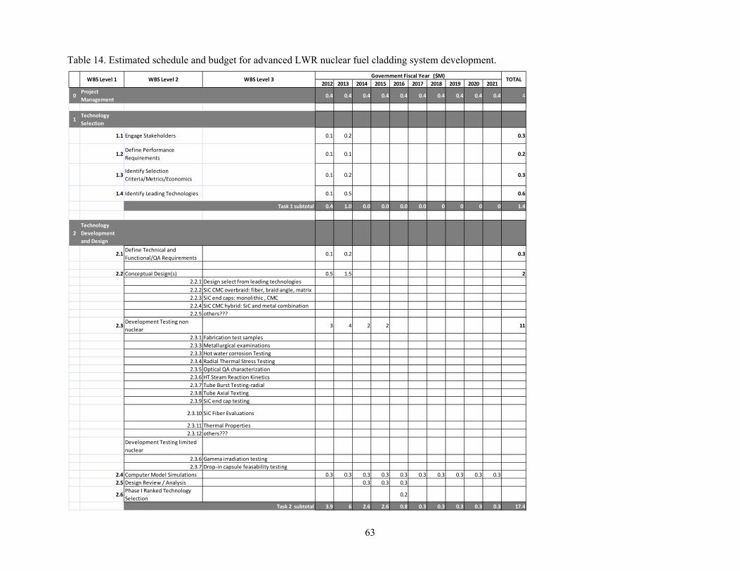
63
Table 14. Estimated schedule and budget for advanced LWR nuclear fuel cladding system development.
2012 2013 2014 2015 2016 2017 2018 2019 2020 2021
0Project
Management0.4 0.4 0.4 0.4 0.4 0.4 0.4 0.4 0.4 0.4 4
1Technology
Selection
1.1 Engage Stakeholders 0.1 0.2 0.3
1.2Define Performance
Requirements0.1 0.1 0.2
1.3Identify Selection
Criteria/Metrics/Economics0.1 0.2 0.3
1.4 Identify Leading Technologies 0.1 0.5 0.6
Task 1 subtotal 0.4 1.0 0.0 0.0 0.0 0.0 0 0 0 0 1.4
2
Technology
Development
and Design
2.1Define Technical and
Functional/QA Requirements0.1 0.2 0.3
2.2 Conceptual Design(s) 0.5 1.5 2
2.2.1 Design select from leading technologies
2.2.2 SiC CMC overbraid: fiber, braid angle, matrix
2.2.3 SiC end caps: monolithic , CMC
2.2.4 SiC CMC hybrid: SiC and metal combination
2.2.5 others???
2.3Development Testing non
nuclear3 4 2 2 11
2.3.1 Fabrication test samples
2.3.3 Metallurgical examinations
2.3.3 Hot water corrosion Testing
2.3.4 Radial Thermal Stress Testing
2.3.5 Optical QA characterization
2.3.6 HT Steam Reaction Kinetics
2.3.7 Tube Burst Testing‐radial
2.3.8 Tube Axial Texting
2.3.9 SiC end cap testing
2.3.10 SiC Fiber Evaluations
2.3.11 Thermal Properties
2.3.12 others???
Development Testing limited
nuclear
2.3.6 Gamma irradiation testing
2.3.7 Drop‐in capsule feasability testing
2.4 Computer Model Simulations 0.3 0.3 0.3 0.3 0.3 0.3 0.3 0.3 0.3 0.3
2.5 Design Review / Analysis 0.3 0.3 0.3
2.6Phase I Ranked Technology
Selection0.2
Task 2 subtotal 3.9 6 2.6 2.6 0.8 0.3 0.3 0.3 0.3 0.3 17.4
Government Fiscal Year ($M)TOTAL WBS Level 1 WBS Level 2 WBS Level 3
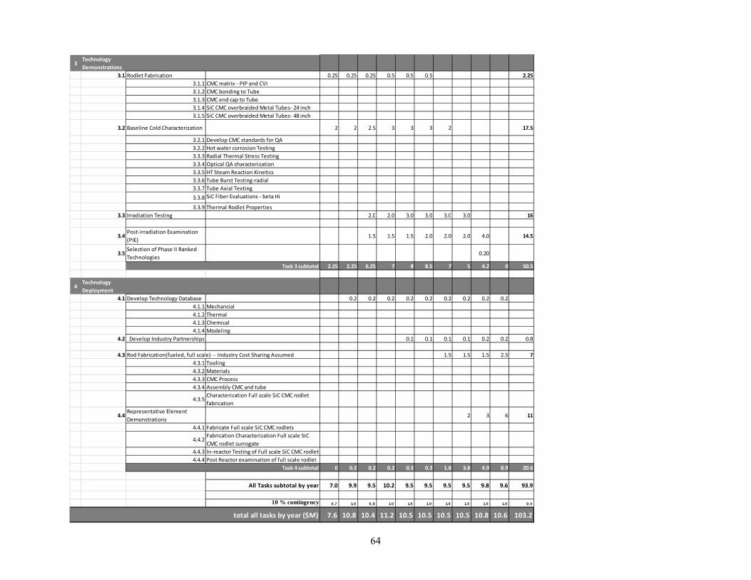
64
3Technology
Demonstrations
3.1 Rodlet Fabrication 0.25 0.25 0.25 0.5 0.5 0.5 2.25
3.1.1 CMC matrix ‐ PIP and CVI
3.1.2 CMC bonding to Tube
3.1.3 CMC end cap to Tube
3.1.4 SiC CMC overbraided Metal Tubes‐ 24 inch
3.1.5 SiC CMC overbraided Metal Tubes‐ 48 inch
3.2 Baseline Cold Characterization 2 2 2.5 3 3 3 2 17.5
3.2.1 Develop CMC standards for QA
3.2.2 Hot water corrosion Testing
3.3.3 Radial Thermal Stress Testing
3.3.4 Optical QA characterization
3.3.5 HT Steam Reaction Kinetics
3.3.6 Tube Burst Testing‐radial
3.3.7 Tube Axial Texting
3.3.8 SiC Fiber Evaluations ‐ beta Hi
Ni l /T3.3.9 Thermal Rodlet Properties
3.3 Irradiation Testing 2.0 2.0 3.0 3.0 3.0 3.0 16
3.4Post‐irradiation Examination
(PIE)1.5 1.5 1.5 2.0 2.0 2.0 4.0 14.5
3.5Selection of Phase II Ranked
Technologies0.20
Task 3 subtotal 2.25 2.25 6.25 7 8 8.5 7 5 4.2 0 50.5
4Technology
Deployment
4.1 Develop Technology Database 0.2 0.2 0.2 0.2 0.2 0.2 0.2 0.2 0.2
4.1.1 Mechancial
4.1.2 Thermal
4.1.3 Chemical
4.1.4 Modeling
4.2 Develop Industry Partnerships 0.1 0.1 0.1 0.1 0.2 0.2 0.8
4.3 Rod Fabrication(fueled, full scale) ‐‐ Industry Cost Sharing Assumed 1.5 1.5 1.5 2.5 7
4.3.1 Tooling
4.3.2 Materials
4.3.3 CMC Process
4.3.4 Assembly CMC and tube
4.3.5Characterization Full scale SiC CMC rodlet
fabrication
4.4Representative Element
Demonstrations 2 3 6 11
4.4.1 Fabricate Full scale SiC CMC rodlets
4.4.2Fabrication Characterization Full scale SiC
CMC rodlet surrogate
4.4.3 In‐reactor Testing of Full scale SiC CMC rodlet
4.4.4 Post Reactor examinaiton of full scale rodlet
Task 4 subtotal 0 0.2 0.2 0.2 0.3 0.3 1.8 3.8 4.9 8.9 20.6
All Tasks subtotal by year 7.0 9.9 9.5 10.2 9.5 9.5 9.5 9.5 9.8 9.6 93.9
10 % contingency 0.7 1.0 0 .9 1.0 1.0 1.0 1.0 1.0 1.0 1.0 9.4
total all tasks by year ($M) 7.6 10.8 10.4 11.2 10.5 10.5 10.5 10.5 10.8 10.6 103.2

65
4. References
1. Idaho National Laboratory, Light Water Reactor Sustainability Program Integrated Program Plan, INL/EXT-11-23452, January 2012.
2 Krishnan, R. and M. Asundi, Zirconium alloys in nuclear technology. Sadhana, 1981. 4(1): p. 41-56
3. Lustman, B., H.G. Rickover, and L.D. Geiger, History of the Development of Zirconium Alloys for use in Nuclear Reactor, E.R.a.D. Administration, Editor. 1975: Washington DC.
4. Lemaignan, C. and A. Motta, Zircoium Alloys in Nuclear Application, in Materials Science and Technology: A Comprehensive Treatment, R.W. Cahn, P. Haasen, and E.L. Kramer, Editors. 1994. p. 1-51.
5. Rudling, P., “High Burnup Fuel Issues,” Nuclear Engineering and Technology. 2007. 40(1): p. 1-8.
6. Franklin, D. and P. Lang, Zirconium-Alloy Corrosion: A Review Based on an International Atomic Energy (IAEA) Meeting, in 9th International Conference of Zirconium in the Nuclear Industry. 1991, ASTM: Kobe, Japan. p. 3-32.
7. Adamson, R., Zirconium-based Alloys in Nuclear Systems Corrosion, in Seminar on Zirconium-based Alloys in Nuclear Systems Presented to INL, May 10-11, 2011. 2011, Idaho National Laboratory: Idaho Falls, ID.
8. Dickson, I.K., H.E. Evans, and K.W. Jones, “A comparison between the uniform and nodular forms of zircaloy corrosion in water reactors,” J. Nucl. Mater. 1979. 80(2): p. 223-231.
9. Bossis, P., et al., “Comparison of the High Burn-up Corrosion on M5 and Low Tin Zircaloy-4,” Journal of ASTM International. 2006. 3(1): p. 494-525.
10. Adamson, R., Dimensional Stability, in Seminar on Zirconium-based Alloys in Nuclear Systems Presented to INL, May 10-11, 2011. 2011, Idaho National Laboratory: Idaho Falls, ID.
11. Franklin, D.G., Zircaloy-4 Cladding Deformation During Power Reactor Irradiation, in Zirconium in the Nuclear Industry: Fifth International Conference. 1982.
12. Rudling, P., Performance Limitation, in Seminar on Zirconium Alloys. 2011, Idaho National Laboratory: Idaho Falls, ID.
13. Matsuo, Y., Creep Behavior of Zircaloy, Cladding Under Variable Conditions, in Zirconium in the Nuclear Industry: Eighth International Symposium. 1989: Philadelphia, Pennsylvania.
14. Adamson, R., F. Garzarolli, et al., Corrosion Mechanisms in Zirconium Alloys. Zirat 12 Special Topic Report, 2007.
15. Pawel, R.E., J.V. Cathcart, and J.J. Campbell, “Oxidation of Zircaloy by Steam,” J. Nucl. Mater. 1979. 82: p. 129.
16. Moalem, M. and D.R. Olander, “Oxidation of Zircaloy by Steam,” J. Nucl. Mater. 1991. 182: p. 170.
66
17. NRC, 10 CFR 50.46, “Acceptance Criteria for Emergency Core Cooling Systems for Light Water Reactors.”
18. Edsinger, K, “EPRI and the zero fuel failures program,” Nuclear News, Dec 2010, p. 40.
19. Jensen, D., “Light Water Reactor Sustainability Program Quality Assurance Program Description Document,” Idaho National Laboratory, INL/MIS-10-19844, Rev. 1. 2012.
20. Crawford, D., et. al, “An Approach to Fuel Development and Qualification,” J. Nucl. Mater. 2007. 371: p. 232.
21. MacDonald, P. E., D. C. Crawford, L. E. Neimark, and J. S. Herring, Technical Basis for the Proposed High Efficiency Nuclear Fuel Program, INEEL/CON-98-00521, and in: International Conference on Nuclear Engineering (ICONE 6), May 10-15, 1998.
22. Naslain, R., “Design, preparation and properties of non-oxide CMCs for application in engines and nuclear reactors: an overview,” Composites Sci. and Tech. 2004. 64(2): p. 155.
23. Principals of Chemical Vapor Deposition, edited by D. Dobkin, Dec 2010, IBSN 978-90-481-6277-2, Kluwer Academic Publishers.
24. Handbook of Chemical Vapor Deposition, Second Edition: Principles, Technology and Applications (Materials Science and Process Technology), ed. by H. Pierson, 1999, ISBN: 0-8155-1432-8.
25. Lange, F.F., W.C. Tu, A.G. Evans, “Processing of damage-tolerant, oxidation-resistant ceramic matrix composites by a precursor infiltration and pyrolysis method,” Materials Science and Engineering: A. 1995. 195: p. 145.
26. Ziegler, G., I. Richter, D. Suttor, "Fiber-reinforced composites with polymer-derived matrix: processing, matrix formation and properties," Composites Part A: Applied Science and Manufacturing.1999. 30: p. 411–417.
27. Kotani, M., Y. Katoh, A. Khyama, "Fabrication and Oxidation-Resistance Property of Allylhydridopolycarbosilane-derived SiC/SiC Composites". Journal of the Ceramic Society of Japan. 2003. 111: p. 300.
28. Rocha, R. M., C. A. A. Cairo, M. L. A. Graca, "Formation of carbon fiber-reinforced ceramic matrix composites with ploysiloxane/silicon derived matrix," Materials Science and Engineering, Part A. 2006. 437: p. 268–273.
29. Technical manuals: Starfire® Systems and KION® Ceraset™.
30. Nechanicky, M.A., K.W. Chew, A. Sellinger and R.M. Laine, “a-Silicon carbide/b-silicon carbide particulate composites via polymer infltration and pyrolysis (PIP) processing using using polymethylsilane,” Journal of the European Ceramic Society. 2000. 20: p. 441-451.
31. Takeda, M. et. al, “Strength of a Hi-Nicalon™/Silicon-Carbide-Matrix Composite Fabricated by the Multiple Polymer Infiltration-Pyrolysis Process,” Journal of the American Ceramic Society. 1999. 82(6): p. 1579–1581.
67
32. Katoh, Y., M. Kotani, H. Kishimoto, W. Yang, A. Kohyama, “Properties and radiation effects in high-temperature pyrolyzed PIP-SiC/SiC,” J. Nucl. Mater. 2001. 289(1-2): p. 42-47.
33. Snead, L.L., M.C. Osborne, R.A. Lowden, J. Strizak, R.J. Shinvaski, K.L. More, W.S. Eatherly, J. Bailey, A.M. Williams, “Low dose irradiation performance of SiC interphase SiC/SiC composites,” J. Nucl. Mater. 1998. 253(1-3): p. 20-30.
34. Katoh, Y., T. Nozawa, M. Kotani, K. Ozawa, A. Kohyama, “Microstructures and Flexural Properties of High Temperature-Pyrolyzed PIP-SiC/SiC Composites,” Key Engineering Materials. 2005. 287: p. 346-351.
35. Esfehanian, M., J. G. Heinrich, J. Horvath, D. Koch, G. Grathwohl, “Silicide-carbide composites obtained from alloyed melt infiltration,” Journal of Materials Science. 2007. 42(18): p. 7721-7728.
36. Sangsuwan, P., S.N. Tewari, J.E. Gatica, M. Singh, and R. Dickerson, “Reactive Infiltration of Silicon Melt Through Microporous Amorphous Carbon Preforms,” Metallurgical and Materials Transactions B: Process Metallurgy and Materials Processing Science. 1999. 30: p. 933-944.
37. Singh, M., T. Jessen and W. Krenkel, Chapter 52: Cost Effective Processing of CMC Composites by Melt Infiltration (Lsi-Process), 25th Annual Conference on Composites, Advanced Ceramics, Materials, and Structures: A, Ceramic Engineering and Science Proceedings. 2008. 22(3): p. 443-454.
38. Brewer, D., “HSR:EPM combustor materials development program,” Mater. Sci. Eng. A. 1999. A261: p. 284-291.
39. Tamuelevicius, S., I. Pozela and M. Andrulevicius, “A simple model of radiation swelling of silicon,” Materials Science and Engineering. 1996. B40: p. 141-146.
40. Katoh, Y., A. Kohyama, T. Nozawa and M. Sato, “SiC/SiC composites through transient eutectic-phase route for fusion applications,” J. Nucl. Mater. 2004. 329(A): p. 587-591.
41. Dong, S.M., Y. Katoh and A. Kohyama, “Preparation of SiC/SiC Composites by Hot Pressing,” J. Ameri. Ceram. Soc. 2003. 86(1): p. 26-32.
42. Koyanagi, T., T. Hinoki, K. Ozawa and Y. Katoh, “Neutron Irradiation Effect on Mechanical Properties of NITE SiC/SiC Composites,” Transactions of the American Nuclear Society. June 2012. 106: p. 1329-1330.
43. Terrani, K.A., Y. Yan, M.P. Brady, T. Cheng, J.R. Keiser, B.A. Pint, L.L. Snead, “Fuel and Cladding Materials Behavior under Accident Scenarios for Current and Advanced LWR Fuel Systems,” Materials Research Society Spring Meeting, San Francisco, CA. 2012.
44. Jones, R. H., C. H. Henager and G. W. Hollenberg, “Composite materials for fusion applications,” Journal of Nuclear Materials. 1992. 191-194(A): p. 75-83.
45. Snead, L. L., R.H. Jones, A. Kohyama and P. Fenici, “Status of silicon carbide composites for fusion,” Journal of Nuclear Materials. 1996. 233–237(1): p. 26-36.
46. Yajima, S., K. Okamura, T. Shishido, et al., “Joining of SiC to SiC using polyborosiloxane,” Am. Ceram. So. Bull. 1981. 60(2): p. 253.

68
47. Donato, A., O. Colombo, M. O. Abadirashid, Ceram. Trans. 1995. 57: p. 431.
48. Lewinsohn, C.A., R. H. Jones, M. Singh, T. Nozawa, M. Kotani, Y. Katoh, A. Kohyama, “Silicon Carbide Based Joining Materials for Fusion Energy and Other High-Temperature, Structural Applications,” in 25th Annual Conference on Composites, Advanced Ceramics, Materials, and Structures: B, Ceramic Engineering and Science Proceedings. 2001. 22(4): p. 621-625.
49. Ferraris, M., C. Badini, M. Montorsi, P. Appendino and H.W. Scholz, “Joining of SiCfSiC composites for thermonuclear fusion reactors,” Journal of Nuclear Materials. 1994. 212-215(B): p. 1613-1616.
50. Rabin, B. H. and G. A. More, J. Mat. Synth. & Proc. 1993. 1: p. 195.
51. Sherwood, W. J., C. K. Whitmarsh, J. M. Jacobs and L. V. Interrante, “Joining Ceramic Composites Using Active Metal/Hpcs Preceramic Polymer Slurries,” in Proceedings of the 21st Annual Conference on Composites, Advanced Ceramics, Materials, and Structures: A, Ceramic Engineering and Science Proceedings. 1997. 18(3): p. 177-182.
52. Halbig, M.C., M. Singh, T.P. Shpargel and J.D. Riser, “Diffusion Bonding of Silicon Carbide Ceramics Using Titanium Interlayers,” in Mechanical Properties and Performance of Engineering Ceramics II: Ceramic Engineering and Science Proceedings, Ceramic Engineering and Science Proceedings. 2006. 27(2): p. 133-143.
53. Radhakrishnan, R., C.H. Henager Jr., J.L. Brimhall and S.B. Bhaduri, “Synthesis of Ti3SiC2/SiC and TiSi2/SiC composites using displacement reactions in the Ti-Si-C system,” Scripta Materialia. 1996. 34(12): p. 1809-1814.
54. Henager, C. H., Y. Shin, Y. Blum, L.A. Giannuzzi, B.W. Kempshall, S.M. Schwarz, “Coatings and joining for SiC and SiC-composites for nuclear energy systems,” Journal of Nuclear Materials. 2007. 367-370(A): p. 1139-1143.
55. Katoh, Y., L.L. Snead, C.H. Henager Jr., A. Hasegawa, A. Kohyama, B. Riccardi and H. Hegeman, “Current status and critical issues for development of SiC composites for fusion applications,” Journal of Nuclear Materials. 2007. 367-370(A): p. 659-671.
56. Nozawa, T., T. Hinoki, A. Hasegawa, A. Kohyama, Y. Katoh, L.L. Snead, C.H. Henager Jr. and J.B.J. Hegeman, Recent advances and issues in development of silicon carbide composites for fusion applications,” Journal of Nuclear Materials. 2009. 386-388: p. 622-627.
57. Ferraris, M., M. Salvo, V. Casalegno, S. Han, Y. Katoh, H.C. Jung, T. Hinoki and A. Kohyama, “Joining of SiC-based materials for nuclear energy applications,” Journal of Nuclear Materials. 2011. 417(1-3): p. 379-382.
58. Ferraris, M., M. Salvo, V. Casalegno, A. Ciampichetti, F. Smeacetto and M. Zucchetti, “Joining of machined SiC/SiC composites for thermonuclear fusion reactors,” Journal of Nuclear Materials. 2008. 375(3): p. 410-415.
59. B. V. Cockeram, “Flexural Strength and Shear Strength of Silicon Carbide to Silicon Carbide Joints Fabricated by a Molybdenum Diffusion Bonding Technique,” Journal of the American Ceramic Society. 2005. 88(7): p. 1892-1899.
69
60. Hinoki, T., N. Eiza, S. Son, K. Shimoda, J. Lee and A. Kohyama,”Development of Joining and Coating Technique for SiC and SiC/SiC Composites Utilizing Nite Processing,” in Mechanical Properties and Performance of Engineering Ceramics and Composites: Ceramic Engineering and Science Proceedings, Ceramic Engineering and Science Proceedings. 2005. 26(2): p. 399-405.
61. Lippmann, W., J. Knorr, R. Wolf, R. Rasper, H. Exner, A.-M. Reinecke, M. Nieher and R. Schreiber, “Laser joining of silicon carbide—a new technology for ultra-high temperature resistant joints,” Nuclear Engineering and Design. 2004. 231(2): p. 151-161.
62. Raffray, A. R., R Jones, G Aiello, M Billone, L Giancarli, H Golfier, A Hasegawa, Y Katoh, A Kohyama, S Nishio, B Riccardi and M.S Tillack, “Design and material issues for high performance SiCf/SiC-based fusion power cores,” Fus. Eng. Des. 2001. 55(1): p. 55-95.
63. Katoh, Y., S. M. Dong and A. Kohyama, “Thermo-mechanical properties and microstructure of silicon carbide composites fabricated by nano-infiltrated transient eutectoid process,” Fus. Eng. and Design. 2002. 61: p. 723-731.
64. Ferraris, M., V. Casalegno, S. Rizzo, M. Salvo, T.O. Van Staveren, J. Matejicek, “Effects of neutron irradiation on glass ceramics as pressure-less joining materials for SiC based components for nuclear applications,” Journal of Nuclear Materials. 2012. 429(1-3): p. 166-172.
65. Mailliart, F., V. Hodaj and N. Eustathopoulos, “Influence of oxygen partial pressure on the wetting of SiC by a Co–Si alloy,” Materials Science and Engineering: A. 2008. 495(1-2): p. 174-180.
66. Coghlan, W.A., F.W. Clinard Jr., N. Itoh and L.R. Greenwood, “Swelling of spinel after low-dose neutron irradiation,” Journal of Nuclear Materials. 1986. 141-143(1): p. 382-386.
67. Katoh, Y., M. Kotani, A. Kohyama, M. Montorsi, M. Salvo and M. Ferraris, “Microstructure and mechanical properties of low-activation glass-ceramic joining and coating for SiC/SiC composites,” Journal of Nuclear Materials. 2000. 283(2): p. 1262-1266.
68. Henager Jr, C.H. and R. J. Kurtz, “Low-activation joining of SiC/SiC composites for fusion applications, Journal of Nuclear Materials. 2011. 417(1-3): p. 375-378.
69. Henager Jr, C. H., Y. Shin, Y. Blum, L.A. Giannuzzi, B.W. Kempshall and S.M. Schwarz, “Coatings and joining for SiC and SiC-composites for nuclear energy systems,” Journal of Nuclear Materials. 2007. 367-370 (B): p. 1139-1143.
70. Henager Jr, C. H., J. L. Brimhall and L. N. Brush, “Tailoring structure and properties of composites synthesized in situ using displacement reactions,” Materials Science and Engineering: A. 1995. 195: p. 65-74.
71. Colombo, P., B Riccardi, A Donato, G Scarinci, “Joining of SiC/SiCf ceramic matrix composites for fusion reactor blanket applications,” Journal of Nuclear Materials. 2000. 278(2-3): p. 127-135.
72. Lewinsohn, C. A., R.H. Jones, P. Colombo and B. Riccardi, “Silicon carbide-based materials for joining silicon carbide composites for fusion energy applications,” Journal of Nuclear Materials. 2002. 307-311(2): p. 1232-1236.
73. Kleebe, H.-J. and Y. D. Blum, “SiOC ceramic with high excess free carbon,” Journal of the European Ceramic Society. 2008. 28(5): p. 1037-1042.
70
74. Blum, Y. D., D. B. MacQueen and H.-J. Kleebe, “Synthesis and characterization of carbon-enriched silicon oxycarbides,” Journal of the European Ceramic Society. 2005. 25(2-3): p. 143-149.
75. Modena, S., G. Domenico Sorarù, Y. Blum and R. Raj, “Passive Oxidation of an Effluent System: The Case of Polymer-Derived SiCO,” Journal of the American Ceramic Society. 2005. 88(2): p. 339-345.
76. Herderick, E. D., K. Cooper and N. Ames, Advanced Materials and Processes, January 2010.
77. Corelli, J. C., J. Hoole, J. Lazzaro and C.W. Lee, “Mechanical, Thermal, and Microstructural Properties of Neutron-Irradiated SiC,” J. Amer. Ceram. Soc. 1983. 66(7): p. 529-538.
78. Matthews, R.B., “Irradiation damage in reaction-bonded silicon carbide,” J. Nucl. Mater. 1974. 51(2): p. 203-208.
79. Matheny, R. A. and J. C. Corelli, “Radiation damage in silicon carbide and graphite for fusion reactor first wall applications,” Journal of Nuclear Materials. 1979. 83(2): p. 313-321.
80. Chaumat, A., Vol EP 0 806 402 B1, 24.01, 2001.
81. Gasse, A., G. Coing-Coyat and G. Bourgeois, (US Patent No 6 221 499 B1.).
82. Gasse, A., US Patent No 2003/0038166 A1.
83. Gasse, A., G. Chaumat and F. Saint-Antonin, 5th International Conference on Joining Ceramics, Glass and Metal, Ed. by M. Turwitt, Jena. 1997.
84. Snead, L. L., T. Nozawa, Y. Katoh, T.-S. Byun, S. Kondo and D.A. Petti, “Handbook of SiC properties for fuel performance modeling,” Journal of Nuclear Materials. 2007. 371(1-3): p. 329-377.
85. Newsome, G. A., L.L. Snead, T. Hinoki, Y. Katoh and D. Peters, “Evaluation of neutron irradiated silicon carbide and silicon carbide composites,” Journal of Nuclear Materials. 2007. 371(1-3): p. 76-89.
86. Katoh, Y., L.L. Snead, C.M. Parish and T. Hinoki, “Observation and Possible Mechanism of Irradiation Induced Creep in Ceramics,” Journal of Nuclear Materials. 2012. In press (available 1 Dec 2012).
87. Hallstadius, L., S. Johnson and E. Lahoda, “Cladding for high performance fuel,” Progress in Nuclear Energy. 2012. 57: p. 71-76.
88. Katoh, Y., L. L. Snead, Report Submitted to LWRS Program, (March 2012).
89. Hirayama,H., T. Kawakubo, A. Goto and T. Kaneko, “Corrosion Behavior of Silicon Carbide in 290°C Water,” J. Amer. Ceram. Soc. 1989. 72(11): p. 2049-2053.
90. Kim, W.J., H.S. Hwang, J.Y. Park and W.S. Ryu, “Corrosion behaviors of sintered and chemically vapor deposited silicon carbide ceramics in water at 360 ◦C,” Journal of Materials Science Letters. 2003. 22: p. 581-584.
71
91. Somiya, S., “Hydrothermal corrosion of nitride and carbide of silicon,” Materials Chemistry and Physics. 2001. 67(1-3): p. 157-164.
92. Oda, K., T. Yoshio, Y. Miyamoto and M. Koizumi, “Hydrothermal Corrosion of Pure, Hot Isostatically Pressed Silicon Nitride,” J. Amer. Ceram. Soc. 1993. 76(5): p. 1365-1368.
93. Stemplien, J. D. et al., MIT CANES Report, 2011.
94. Opila, E. J., “Variation of the Oxidation Rate of Silicon Carbide with Water-Vapor Pressure,” Journal of the American Ceramic Society. 1999. 82(3): p. 625-636.
95. Cheng, T., J.R. Keiser, M.P. Bradfy, K.A. Terrani and B.A. Pint, “Oxidation of fuel cladding candidate materials in steam environments at high temperature and pressure,” J. Nucl. Mat. 2012. 427(1-3): p. 396-400.
96. Nuclear Energy Institute: Ventyx Velocity Suite; Energy Resources International, Inc., http://www.NEI.org, May 2011.
97. US NRC, “AP-1000 Design Control Document Rev. 16,” Tier 2, Chapter 4, Section 4.1, ML071580895 (2007).
98. Cohen, K.P., The theory of isotope separation as applied to the large-scale production of U235, McGraw-Hill, 1951.
99. Benedict, M., T.H. Pigford and H.W. Levi, Nuclear Chemical Engineering, McGraw-Hill, 1981.
100. Shropshire, D.E., et al., “Advanced Fuel Cycle Cost Basis,” INL/EXT-07-12107, Rev. 2, Dec 2009.
101. Hurley, D.H. and J. B. Spicer, “Point-Source Representation for Laser-Generated Ultrasound in an Elastic Transversely Isotropic Half Space,” Journal of Applied Physics. 1999. 86: p. 3423.
102. Hurley, D.H. and J. B. Spicer, An Investigation of the Effects of Material Anisotropy and Heterogeneity on Pulsed, Laser-Generated Acoustic Signals, Ultrasonics Ferroelectrics and Frequency Control. 1999. 46: p. 1387.
103. Katoh, Y., L. L. Snead, T. Nozawa, S. Kondo and J. T. Busby, “Thermophysical and mechanical properties of near-stoichiometric fiber CVI SiC/SiC composites after neutron irradiation at elevated temperatures,” Journal of Nuclear Materials. 2010. 403(1-3): p. 48-61.
104. Khafizov, M., D.H. Hurley, “Measurement of Thermal Transport Using Time-resolved Thermal Wave Microscopy,” Journal of Applied Physics. 2011. 110(8): p. 83525.
105. Hurley, D.H., M. Khafizov, and S. Shinde, “Measurement of Kaptiza Resistance Across a Bicrystal Interface,” Journal of Applied Physics. 2011. 109(8): p. 83504.
106. Idaho National Laboratory external document. FY 2009 Advanced Test Reactor National Scientific User Facility Users’ Guide, INL/EXT-08-14709,
107. Gaston, D., C. Newman, G. Hansen, and D. Lebrun-Grandie, “MOOSE: A Parallel Computational Framework for Coupled Systems of Nonlinear Equations,” Nuclear Engineering and Design. 2009. 239: p. 1768.
72
108. Tonks, M.R., D. Gaston, P.C. Millett, D. Andrs and P. Talbot, “An Object-Oriented Finite Element Framework for Multiphysics Phase Field Simulations,” Computational Material Science. 2012. 51: p. 20-29.
109. Rashid, Y., R. Dunham and R. Montgomery, Fuel Analysis and Licensing Code: FALCON MOD01, EPRI Report 1011308, December 2004.
110. Williamson, R. L., J.D. Hales, S.R. Novascone, M.R. Tonks, D.R. Gaston, C.J. Permann, D. Andrs and R.C. Martineau, “Multidimensional Multiphysics Simulation of Nuclear Fuel Behavior,” Journal of Nuclear Materials. 2012. 423: p. 149-163.
111. Barrett, K. E., “Research and Development Drop-in Capsule Advanced Test Reactor Irradiation Experiment For The Light Water Reactor Sustainability (LWRS) Non-Fueled Cladding Experiments,” Idaho National Laboratory, TFR-731, Rev. 0, 2011.
112. Pettit, M., “Conduct of Engineering”, Idaho National Laboratory, PDD-10000, Rev. 1, 2011.
113. van Rooyen, I., “Cold Characterization Plan for the LWRS-1 Hybrid SiC-CMC Zircalloy-4 Experiments”, Idaho National Laboratory, PLN-3927, Rev. 0, 2011.
114. Henager Jr., C.H., A.L. Schemer-Kohrn, S.G. Pitman, D.J. Senor, K.J. Geelhood, and C.L. Painter, “ Pitting Corrosion in CVD SiC at 300OC in Deoxygenated High-Purity Water,” J. Nucl. Mater. 2008. 378: p. 9-16.
115. Kim, W.-J., H.S. Hwang, and J. Y. Park, “Corrosion Behavior of Reaction-Bonded Silicon Carbide Ceramics in High-Temperature Water,” J. Mater Sci Lett. 2002. 21: p. 733-735.
116. Kim, W.-J., H.S. Hwang, J. Y. Park, and W.-S. Ryu, “Corrosion Behaviors of Sintered and Chemically Vapor Deposited Silicon Carbide Ceramics in Water at 360OC,” J. Mater Sci Lett. 2003. 22: p. 581-584.
117. Hirayama, H., T. Kawakubo, A. Goto, and T. Kaneko, “Corrosion behavior of Silicon Carbide in 290OC Water,” J. Am. Ceram. Soc. 1989. 72(11): p. 2049-2053.
118. Barringer, E., Z. Faiztompkins, H. Feinroth, T. Allen, M. Lance, H. Meyer, L. Walker, and E. Lara-Curzio, “Corrosion of CVD Silicon Carbide in 500OC Supercritical Water,” J. Am. Ceram. Soc. 2007. 90: p. 315-318.
119. Jacobson, N., D. Myers, E. Opila and E. Copland, “Interactions of Water Vapor with Oxides at Elevated Temperatures,” J. Phys. Chem. Solids. 2005. 66: p. 471-478.
120. Opila, E.J., “Oxidation and Volitilazation of Silica Formers in Water Vapor,” J. Am. Ceram. Soc. 2003, 86: p. 1238-1248.
121. Opila, E.J., “Variation of the Oxidation Rate of Silicon Carbide with Water-Vapor Pressure,” J. Am. Ceram. Soc. 1999. 82: p. 625-636.
122. Chapman, R. H., J. V. Cathcart, and D. O. Hobson, “Status of Zircaloy Deformation and Oxidation Research at Oak Ridge National Laboratory,” CSNI Specialist's Meeting on the Behavior of Water Reactor Fuel Elements under Accident Conditions, Nord-Torpa, Norway, September 13-16, 1976.
73
123. Fuel Cladding Failure Criteria- Final Report, European Commission on Nuclear Safety and the Environment, September, 1999.
124. Ambrosek, R., “Technical Evaluation of MD-MOX and LWR-1 Tests for Influence on Safety Envelope,” Idaho National Laboratory, EDF-4336, Rev.0 (2004).
125. Idaho National Laboratory Drawing number 602812, Rev. 3,“ATR Light Water Reactor Sustainability (LWRS) "I" Hole Capsule Irradiation Experiment Assembly and Details” (2011).
126. Glass, C., “LWRS Scoping Analysis Summary”, Idaho National Laboratory Interoffice Memo, Glass Letter File CRG-01-2011, Rev. 0 (2011).
127. Idaho National Laboratory, “FY 2009 Advanced Test Reactor National Scientific User Facility Users’ Guide”, INL/EXT-08-14709, 2009.
128. Oak Ridge National Laboratory High Flux Isotope Reactor website: http://neutrons.ornl.gov/facilities/HFIR/
129. Ott, L. J., B. B. Bevard, R. J. Ellis, J. L. McDufee, and D. J. Spellman, “Advanced Fuel/Cladding Testing Capabilities in the ORNL High Flux Isotope Reactor,” Proceedings of Top Fuel 2009, Paris, France, September 6-10, 2009, Paper 2039.
130. Institute for energiteknikk, OECD HALDEN REACTOR PROJECT Website: http://www.ife.no
131. Massachusetts Institute of Technology Nuclear Reactor Laboratory Website: http://web.mit.edu/nrl/www/
132. Nishyabu, K., et al, “Development of Silicon Carbide Heat-Resistant Composites with Micro-Porous Structure,” in proceedings of the 16th International Conference on Composite Materials, Kyoto, Japan. 2007.
133. “Polymer Derived Ceramics: From Nano-Structure to Applications”, edited by P. Colombo, R. Reidel and G. Soranu; ISBN-13: 9781605950006; Publisher: DEStech Publications, Inc. 2009.

74
5. Appendix
Appendix A – Materials Characterization Test Techniques and Test Facilities
Appendix B – Potential Irradiation Test Facilities
Appendix C – Post-Irradiation Examination Capabilities at INL and ORNL
Appendix D – Example As-built Data Package Process Worksheet and Checklist

75
Appendix A – Materials Characterization Test Techniques and Test Facilities
INL Laser-based Thermal Properties Laboratory The laser-based thermal properties laboratory has developed and is continuing to develop laser-based thermal conductivity and thermal diffusivity probes. The emphasis of our approach is to provide spatially resolved thermal properties measurements. Currently the focus of the laboratory is spatially resolved measurement of thermal conductivity and diffusivity of uranium oxide. This effort spans the spectrum from fundamental studies of phonon transport across nanometer thick single crystal films to measurement of the thermal diffusivity radial profile across a spent nuclear fuel element. The spatial resolution provided by these laser-based measurements ranges from ~10 nm in the depth direction to ~ 10 microns in the lateral direction. This effort is partially funded by the Center for Materials Science of Nuclear Fuel, an Energy Frontier Research Center based at INL. The Fuels Cycle Research and Development program also provides substantial funding for measurement of radiological samples. Hot Cell Capabilities
Scanning Thermal Diffusivity Microscope installed in a hot cell in the Analytical Laboratory the Materials and Fuels Complex at INL
Provide thermal diffusivity data with ~ 100 micron resolution Capable of measuring spent nuclear fuel Measure thermal properties from room temperature to 400C
Lab-based Capabilities
Thermal diffusivity with nanometer depth resolution and micron lateral resolution Purely laser-based thermal conductivity probe (no need to separately measure specific heat) Unique capability to measure the influence of individual microstructure features on thermal
transport Can conduct measurement at cryogenic temperatures to freeze out phonon-phonon scattering (for
phonon mediated thermal transport)
Figure 19. Left: Scanning thermal diffusivity microscope. This instrument, installed in a radiation hot cell at INL, is capable of measuring thermal transport in spent nuclear fuel. Right: Time resolved thermal wave microscope. Capable of measuring thermal transport with nanometer resolution in the depth direction and micron resolution in the lateral direction.

76
INL Laser Based Mechanical Properties Laboratory Located in labs C10A and B3 in the INL Research Center (IRC) are the capabilities to probe mechanical properties of materials using laser ultrasound (LUS) and associated techniques. Measurements are made in the time domain and the frequency domain. In the frequency domain measurements are made using laser based resonant ultrasound (RUS). This technique reveals the elastic constants of an anisotropic material and information about the material’s attenuation characteristics. Attenuation provides information about dislocation density and the onset of micro cracking. As an example, acoustic attenuation measured in a fiber composite material reveals information about the state of the fiber matrix bond. Attenuation increases as damage (i.e. debonding) accumulates. The apparatus for conducting RUS measurements resides in lab C10.
In the time domain, laser ultrasound illuminates spatially resolved elastic constants for isotropic materials. The RUS apparatus in C10 is capable of these measurements, as is the Mechanical Properties Microscope (MPM) in lab B3. The MPM is slated for eventual installation in a hot cell at MFC. Currently it is undergoing testing and refinement at IRC. Standard NDE applications of ultrasound, both laser based and contacting, can also be conducted in these labs.
Lab C10 features an Instron MicroTester for doing conventional strength of materials experiments. The load frame can be instrumented for either contact or laser ultrasound data capture. With this load frame, standard compression or extension tests and three point bend tests can be conducted on small samples. Two furnaces are available for making measurements at elevated temperatures. A Lindberg tube furnace that heats to 1500°C in air or an inert atmosphere is available. Also available is a prototype furnace for small samples that heats to 400°C in an inert atmosphere or under vacuum. Laser based measurements can be made on a sample via windows on the furnaces in near real time, or samples can be inspected pre- and post-heating using the LUS setups in each lab.
Figure 20. Mechanical Properties Microscope
Figure 21. Instron Model 5848 MicroTester
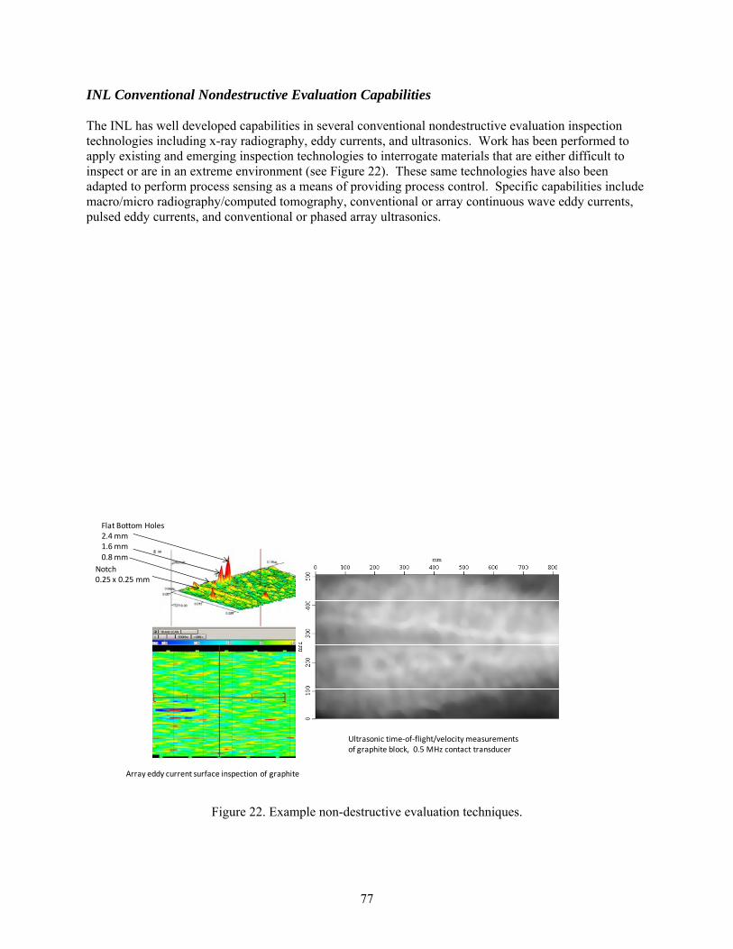
77
INL Conventional Nondestructive Evaluation Capabilities The INL has well developed capabilities in several conventional nondestructive evaluation inspection technologies including x-ray radiography, eddy currents, and ultrasonics. Work has been performed to apply existing and emerging inspection technologies to interrogate materials that are either difficult to inspect or are in an extreme environment (see Figure 22). These same technologies have also been adapted to perform process sensing as a means of providing process control. Specific capabilities include macro/micro radiography/computed tomography, conventional or array continuous wave eddy currents, pulsed eddy currents, and conventional or phased array ultrasonics.
Figure 22. Example non-destructive evaluation techniques.
Flat Bottom Holes2.4 mm1.6 mm0.8 mm
Notch0.25 x 0.25 mm
Ultrasonic time‐of‐flight/velocity measurements of graphite block, 0.5 MHz contact transducer
Array eddy current surface inspection of graphite
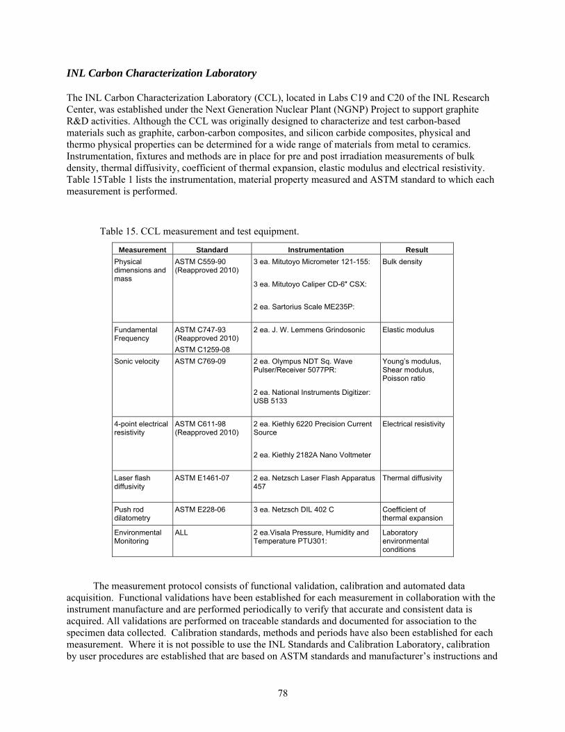
78
INL Carbon Characterization Laboratory The INL Carbon Characterization Laboratory (CCL), located in Labs C19 and C20 of the INL Research Center, was established under the Next Generation Nuclear Plant (NGNP) Project to support graphite R&D activities. Although the CCL was originally designed to characterize and test carbon-based materials such as graphite, carbon-carbon composites, and silicon carbide composites, physical and thermo physical properties can be determined for a wide range of materials from metal to ceramics. Instrumentation, fixtures and methods are in place for pre and post irradiation measurements of bulk density, thermal diffusivity, coefficient of thermal expansion, elastic modulus and electrical resistivity. Table 15Table 1 lists the instrumentation, material property measured and ASTM standard to which each measurement is performed.
Table 15. CCL measurement and test equipment.
Measurement Standard Instrumentation Result
Physical dimensions and mass
ASTM C559-90 (Reapproved 2010)
3 ea. Mitutoyo Micrometer 121-155:
3 ea. Mitutoyo Caliper CD-6″ CSX:
2 ea. Sartorius Scale ME235P:
Bulk density
Fundamental Frequency
ASTM C747-93 (Reapproved 2010)
ASTM C1259-08
2 ea. J. W. Lemmens Grindosonic
Elastic modulus
Sonic velocity ASTM C769-09 2 ea. Olympus NDT Sq. Wave Pulser/Receiver 5077PR:
2 ea. National Instruments Digitizer: USB 5133
Young’s modulus, Shear modulus, Poisson ratio
4-point electrical resistivity
ASTM C611-98 (Reapproved 2010)
2 ea. Kiethly 6220 Precision Current Source
2 ea. Kiethly 2182A Nano Voltmeter
Electrical resistivity
Laser flash diffusivity
ASTM E1461-07 2 ea. Netzsch Laser Flash Apparatus 457
Thermal diffusivity
Push rod dilatometry
ASTM E228-06 3 ea. Netzsch DIL 402 C
Coefficient of thermal expansion
Environmental Monitoring
ALL 2 ea.Visala Pressure, Humidity and Temperature PTU301:
Laboratory environmental conditions
The measurement protocol consists of functional validation, calibration and automated data acquisition. Functional validations have been established for each measurement in collaboration with the instrument manufacture and are performed periodically to verify that accurate and consistent data is acquired. All validations are performed on traceable standards and documented for association to the specimen data collected. Calibration standards, methods and periods have also been established for each measurement. Where it is not possible to use the INL Standards and Calibration Laboratory, calibration by user procedures are established that are based on ASTM standards and manufacturer’s instructions and
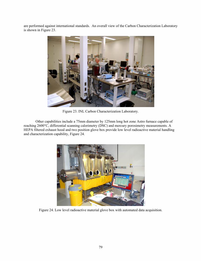
79
are performed against international standards. An overall view of the Carbon Characterization Laboratory is shown in Figure 23.
Figure 23. INL Carbon Characterization Laboratory.
Other capabilities include a 75mm diameter by 125mm long hot zone Astro furnace capable of reaching 2600°C, differential scanning calorimetry (DSC) and mercury porosimetry measurements. A HEPA filtered exhaust hood and two position glove box provide low level radioactive material handling and characterization capability, Figure 24.
Figure 24. Low level radioactive material glove box with automated data acquisition.
80
Appendix B – Potential Reactor Test Facilities
The Idaho National Laboratory Advanced Test Reactor The Advanced Test Reactor is one of the premier test reactors in the United States. The reactor provides a very high neutron and gamma radiation source for testing of nuclear fuels and materials. The configuration of the reactor is shown in Figure 25. The reactor has multiple test locations with a unique control system that allows multiple experiment conditions to be controlled. The reactor has a very high neutron fluxes, thermal neutron fluxes of up to 1x10¹⁵ n/cm2-s, fast neutrons fluxes of 5x10¹⁴ n/cm2-s, and fast/thermal flux ratios of 0.1 – 1.0. The arrangement of the core allows for multiple large testing locations. Typical experiments include sealed capsules where the test material isn’t required to be in the reactor cooling water. More advanced tests can be performed where the test samples are exposed to the cooling water. This allows for the effects of water chemistry and radiation to be observed. The most demanding conditions for testing are created when the samples are placed in a pressurized loop that simulates the pressure and temperatures observed in commercial reactors. The pressurized loop also uses coolant that simulates commercial reactor cooling water. The high neutron flux in the ATR allows samples to simulate the typical lifetime of nuclear materials relatively quickly.
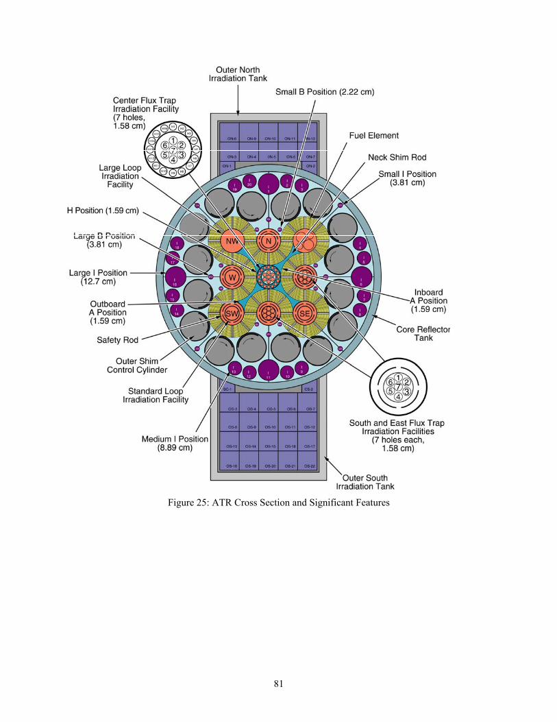
81
Figure 25: ATR Cross Section and Significant Features
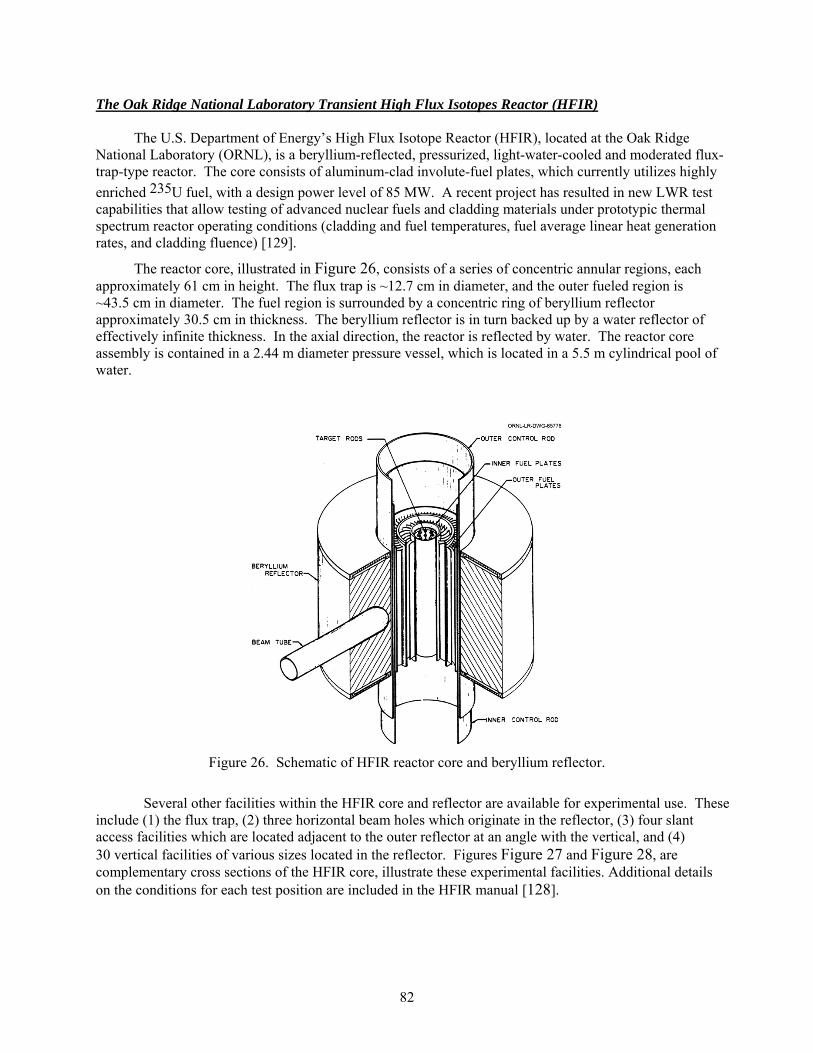
82
The Oak Ridge National Laboratory Transient High Flux Isotopes Reactor (HFIR)
The U.S. Department of Energy’s High Flux Isotope Reactor (HFIR), located at the Oak Ridge National Laboratory (ORNL), is a beryllium-reflected, pressurized, light-water-cooled and moderated flux-trap-type reactor. The core consists of aluminum-clad involute-fuel plates, which currently utilizes highly
enriched 235U fuel, with a design power level of 85 MW. A recent project has resulted in new LWR test capabilities that allow testing of advanced nuclear fuels and cladding materials under prototypic thermal spectrum reactor operating conditions (cladding and fuel temperatures, fuel average linear heat generation rates, and cladding fluence) [129].
The reactor core, illustrated in Figure 26, consists of a series of concentric annular regions, each approximately 61 cm in height. The flux trap is ~12.7 cm in diameter, and the outer fueled region is ~43.5 cm in diameter. The fuel region is surrounded by a concentric ring of beryllium reflector approximately 30.5 cm in thickness. The beryllium reflector is in turn backed up by a water reflector of effectively infinite thickness. In the axial direction, the reactor is reflected by water. The reactor core assembly is contained in a 2.44 m diameter pressure vessel, which is located in a 5.5 m cylindrical pool of water.
Figure 26. Schematic of HFIR reactor core and beryllium reflector.
Several other facilities within the HFIR core and reflector are available for experimental use. These include (1) the flux trap, (2) three horizontal beam holes which originate in the reflector, (3) four slant access facilities which are located adjacent to the outer reflector at an angle with the vertical, and (4) 30 vertical facilities of various sizes located in the reflector. Figures Figure 27 and Figure 28, are complementary cross sections of the HFIR core, illustrate these experimental facilities. Additional details on the conditions for each test position are included in the HFIR manual [128].

83
Figure 27. Cross section through HFIR midplane.
Figure 28. Cross section through HFIR midplane providing additional detail.
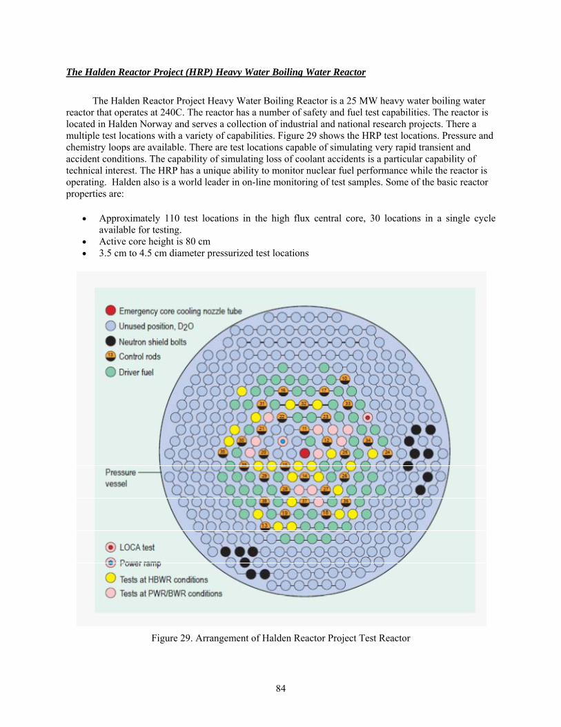
84
The Halden Reactor Project (HRP) Heavy Water Boiling Water Reactor
The Halden Reactor Project Heavy Water Boiling Reactor is a 25 MW heavy water boiling water reactor that operates at 240C. The reactor has a number of safety and fuel test capabilities. The reactor is located in Halden Norway and serves a collection of industrial and national research projects. There a multiple test locations with a variety of capabilities. Figure 29 shows the HRP test locations. Pressure and chemistry loops are available. There are test locations capable of simulating very rapid transient and accident conditions. The capability of simulating loss of coolant accidents is a particular capability of technical interest. The HRP has a unique ability to monitor nuclear fuel performance while the reactor is operating. Halden also is a world leader in on-line monitoring of test samples. Some of the basic reactor properties are:
Approximately 110 test locations in the high flux central core, 30 locations in a single cycle available for testing.
Active core height is 80 cm 3.5 cm to 4.5 cm diameter pressurized test locations
Figure 29. Arrangement of Halden Reactor Project Test Reactor
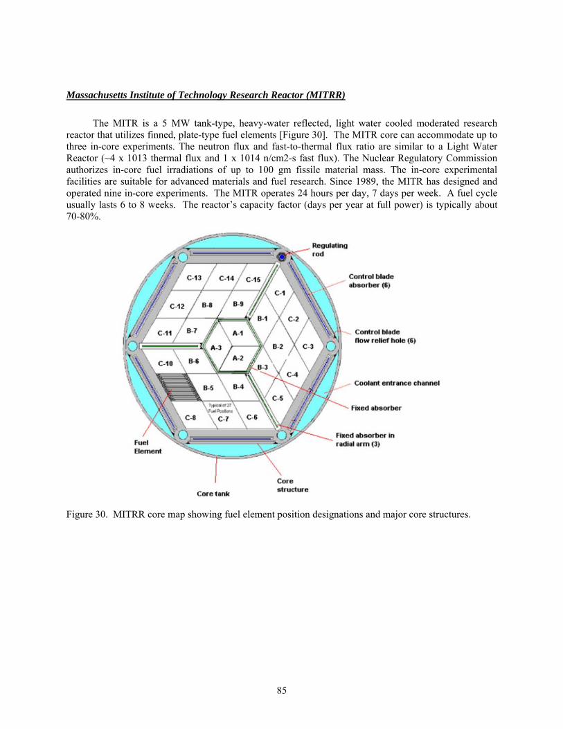
85
Massachusetts Institute of Technology Research Reactor (MITRR)
The MITR is a 5 MW tank-type, heavy-water reflected, light water cooled moderated research reactor that utilizes finned, plate-type fuel elements [Figure 30]. The MITR core can accommodate up to three in-core experiments. The neutron flux and fast-to-thermal flux ratio are similar to a Light Water Reactor (~4 x 10¹³ thermal flux and 1 x 10¹⁴ n/cm2-s fast flux). The Nuclear Regulatory Commission authorizes in-core fuel irradiations of up to 100 gm fissile material mass. The in-core experimental facilities are suitable for advanced materials and fuel research. Since 1989, the MITR has designed and operated nine in-core experiments. The MITR operates 24 hours per day, 7 days per week. A fuel cycle usually lasts 6 to 8 weeks. The reactor’s capacity factor (days per year at full power) is typically about 70-80%.
Figure 30. MITRR core map showing fuel element position designations and major core structures.

86
The Idaho National Laboratory Transient Reactor Test Facility (TREAT) Reactor (not yet operational)
TREAT reactor is an air-cooled, thermal, test reactor designed to test reactor fuels and structural materials during the severe conditions seen during rapid power increases in a nuclear reactor. The reactor was mothballed in 1994 and is undergoing restart analysis to fill a critical testing roll for the Department of Energy and commercial interests. The TREAT reactor consists of a 19x19 array of fuel and reflector assemblies. Surrounding the reactor is a graphite reflector. The fuel elements have UO2 distributed in carbon. The close coupling of the fuel to the moderator allows rapid heat transfer to the carbon. The induced rapid heating of the carbon moderator as the power is produced quickly reduces the cores ability to make power. This results in a very short pulse power that can simulate a variety of reactor events. A schematic of the TREAT reactor is shown in Figure 31.
Figure 31. TREAT Reactor schematic.
The TREAT reactor can create a very rapid high power transient capable of simulating severe reactor damaging events. Damage to nuclear fuel caused by excess energy input in the simulated transient can create melting, water reactions between the fuel or cladding with the water coolant and damage localized to the ceramic fuel. These simulated events help define the operating behavior of nuclear fuel at the extremes of the performance envelope.
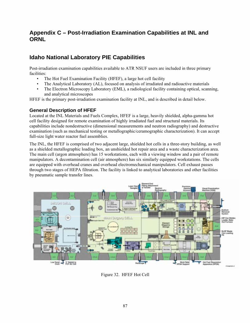
87
Appendix C – Post-Irradiation Examination Capabilities at INL and ORNL
Idaho National Laboratory PIE Capabilities Post-irradiation examination capabilities available to ATR NSUF users are included in three primary facilities:
• The Hot Fuel Examination Facility (HFEF), a large hot cell facility • The Analytical Laboratory (AL), focused on analysis of irradiated and radioactive materials • The Electron Microscopy Laboratory (EML), a radiological facility containing optical, scanning,
and analytical microscopes HFEF is the primary post-irradiation examination facility at INL, and is described in detail below. General Description of HFEF Located at the INL Materials and Fuels Complex, HFEF is a large, heavily shielded, alpha-gamma hot cell facility designed for remote examination of highly irradiated fuel and structural materials. Its capabilities include nondestructive (dimensional measurements and neutron radiography) and destructive examination (such as mechanical testing or metallographic/ceramographic characterization). It can accept full-size light water reactor fuel assemblies.
The INL, the HFEF is comprised of two adjacent large, shielded hot cells in a three-story building, as well as a shielded metallographic loading box, an unshielded hot repair area and a waste characterization area. The main cell (argon atmosphere) has 15 workstations, each with a viewing window and a pair of remote manipulators. A decontamination cell (air atmosphere) has six similarly equipped workstations. The cells are equipped with overhead cranes and overhead electromechanical manipulators. Cell exhaust passes through two stages of HEPA filtration. The facility is linked to analytical laboratories and other facilities by pneumatic sample transfer lines.
Figure 32. HFEF Hot Cell

88
Figure 33. HFEF Hot Cell Windows and Manipulators
HFEF Process Areas and Equipment Locations Each main cell work station has removable electrical and lighting feed-throughs that can be changed to accommodate the mission of the station. The main cell is equipped with two rapid insertion ports for quick transfer of small tools and items into the cell.
The decontamination cell contains a spray chamber for decontaminating equipment and non-fissile material using a manipulator-held wand. Material handling takes place via a 750-lb electro-mechanical manipulator, a 5-ton crane and six sets of master-slave manipulators.
The hot repair area is available for contact maintenance on cell equipment; it can also be used for transfer of equipment and materials to or from the decontamination cell. HFEF also has a 250 kW Training Research Isotope General Atomics (TRIGA) reactor, for neutron radiography irradiation to examine internal features of fuel elements and assemblies.
Examination Equipment The destructive and non-destructive examination capabilities listed below are available. HFEF NDE Capabilities Non-Destructive Examinations Equipment Used Neutron radiography 250 kW TRIGA reactor Element/capsule diameter measurements Element Contact Profilometer Element/capsule gas sampling Gas Assay Sample and Recharge Element/capsule weight Element/Capsule Balance (Mettler) Element/capsule fission and activation product distribution Precision Gamma Scanning Element/capsule bowing and length Bow and Length Machine Element/capsule visual exam Visual Exam Machine Macro photography High resolution digital photography High precision specific gravity measurements Pycnometer
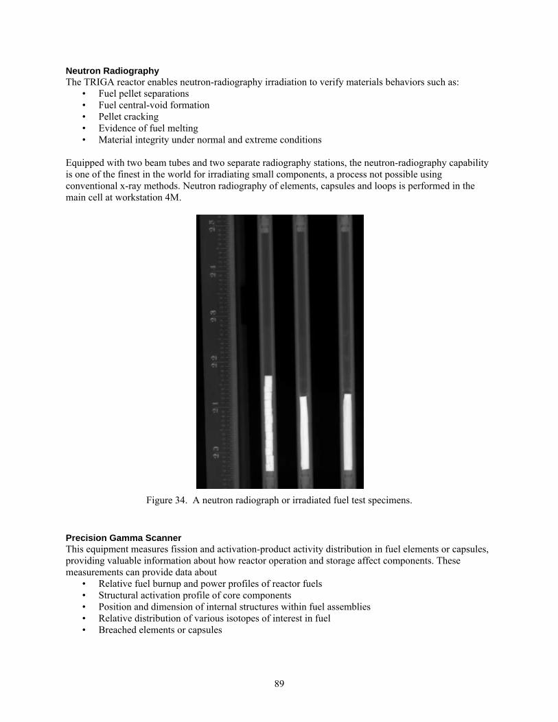
89
Neutron Radiography The TRIGA reactor enables neutron-radiography irradiation to verify materials behaviors such as:
• Fuel pellet separations • Fuel central-void formation • Pellet cracking • Evidence of fuel melting • Material integrity under normal and extreme conditions
Equipped with two beam tubes and two separate radiography stations, the neutron-radiography capability is one of the finest in the world for irradiating small components, a process not possible using conventional x-ray methods. Neutron radiography of elements, capsules and loops is performed in the main cell at workstation 4M.
Figure 34. A neutron radiograph or irradiated fuel test specimens.
Precision Gamma Scanner This equipment measures fission and activation-product activity distribution in fuel elements or capsules, providing valuable information about how reactor operation and storage affect components. These measurements can provide data about
• Relative fuel burnup and power profiles of reactor fuels • Structural activation profile of core components • Position and dimension of internal structures within fuel assemblies • Relative distribution of various isotopes of interest in fuel • Breached elements or capsules
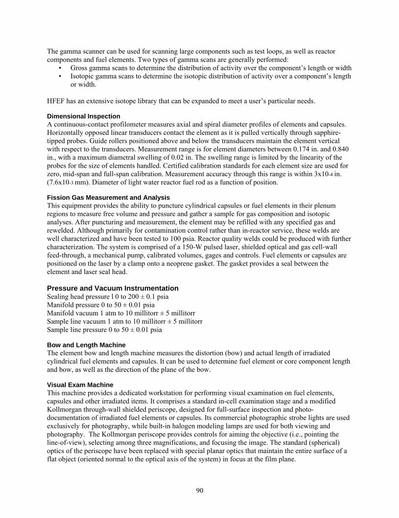
90
The gamma scanner can be used for scanning large components such as test loops, as well as reactor components and fuel elements. Two types of gamma scans are generally performed:
• Gross gamma scans to determine the distribution of activity over the component’s length or width • Isotopic gamma scans to determine the isotopic distribution of activity over a component’s length
or width.
HFEF has an extensive isotope library that can be expanded to meet a user’s particular needs. Dimensional Inspection A continuous-contact profilometer measures axial and spiral diameter profiles of elements and capsules. Horizontally opposed linear transducers contact the element as it is pulled vertically through sapphire-tipped probes. Guide rollers positioned above and below the transducers maintain the element vertical with respect to the transducers. Measurement range is for element diameters between 0.174 in. and 0.840 in., with a maximum diametral swelling of 0.02 in. The swelling range is limited by the linearity of the probes for the size of elements handled. Certified calibration standards for each element size are used for zero, mid-span and full-span calibration. Measurement accuracy through this range is within 3x10⁻⁴ in. (7.6x10⁻³ mm). Diameter of light water reactor fuel rod as a function of position. Fission Gas Measurement and Analysis This equipment provides the ability to puncture cylindrical capsules or fuel elements in their plenum regions to measure free volume and pressure and gather a sample for gas composition and isotopic analyses. After puncturing and measurement, the element may be refilled with any specified gas and rewelded. Although primarily for contamination control rather than in-reactor service, these welds are well characterized and have been tested to 100 psia. Reactor quality welds could be produced with further characterization. The system is comprised of a 150-W pulsed laser, shielded optical and gas cell-wall feed-through, a mechanical pump, calibrated volumes, gages and controls. Fuel elements or capsules are positioned on the laser by a clamp onto a neoprene gasket. The gasket provides a seal between the element and laser seal head. Pressure and Vacuum Instrumentation Sealing head pressure l 0 to 200 ± 0.1 psia Manifold pressure 0 to 50 ± 0.01 psia Manifold vacuum 1 atm to 10 millitorr ± 5 millitorr Sample line vacuum 1 atm to 10 millitorr ± 5 millitorr Sample line pressure 0 to 50 ± 0.01 psia Bow and Length Machine The element bow and length machine measures the distortion (bow) and actual length of irradiated cylindrical fuel elements and capsules. It can be used to determine fuel element or core component length and bow, as well as the direction of the plane of the bow. Visual Exam Machine This machine provides a dedicated workstation for performing visual examination on fuel elements, capsules and other irradiated items. It comprises a standard in-cell examination stage and a modified Kollmorgan through-wall shielded periscope, designed for full-surface inspection and photo-documentation of irradiated fuel elements or capsules. Its commercial photographic strobe lights are used exclusively for photography, while built-in halogen modeling lamps are used for both viewing and photography. The Kollmorgan periscope provides controls for aiming the objective (i.e., pointing the line-of-view), selecting among three magnifications, and focusing the image. The standard (spherical) optics of the periscope have been replaced with special planar optics that maintain the entire surface of a flat object (oriented normal to the optical axis of the system) in focus at the film plane.
91
Figure 35. Visual image of features on a light water reactor fuel rod.
Eddy Current Testing Eddy current inspection capability is being developed to perform oxide film thickness and defect detection on both rod type and flat plate specimens. This capability is being integrated with the visual examination Stage. Destructive Examination Equipment Destructive examination capabilities are available for characterizing spent nuclear fuel and other irradiated materials. The following table lists the destructive examinations and the equipment used to perform the examinations. Brief descriptions of the equipment follow. HFEF Destructive Exam Capability Destructive Exams Equipment Used Sample cutting and preparation - Containment box in main cell Zone 2M Mounting samples in metallographic mount - Containment box in main cell Zone 2 M Fuel sample visual exam and photography - Leitz metallograph in metallographic loading box Detailed photography of sample - High resolution digital photography Scanning Electron Microscopy - SEM in metallographic loading box Microhardness - Leitz metallograph in metallographic loading box Punch samples TEM sample preparation - Subassembly Hex-Can punch/sample thinning Zones 3M and 2M Sample Preparation (Containment Box) Irradiated fuel, cladding and structural materials are sectioned, mounted into metallographic bases, ground and polished in the containment box located in the HFEF main cell. The containment box has its own argon atmosphere and atmosphere control system to prevent cross contamination with the main cell. Irradiated samples prepared in the containment box are pneumatically transferred to the box, where they are examined by either the Leitz metallograph or a digital microhardness tester. The pneumatic transfer system also connects to the Analytical Laboratory. Metallography HFEF houses a shielded metallography cell connected to the main cell via pneumatic transfer tube. The containment box operates under nitrogen or argon atmosphere to prevent rapid oxidation of sample surfaces. Metallographic images of irradiated specimens can be acquired using either a Leitz metallograph or the optical system of the LECO AMH43 microhardness tester.
92
Microhardness A LECO AMH43 automatic microhardness tests is located in the HEFF metallography cell. The microhardness tester is capable of applying loads from 10g to 1 kg. The sample stage can be position
controlled to within ±1μm. Image acquisition is through a high resolution CCD camera. Chemical and Isotopic Analysis The Materials and Fuels Complex Analytical Laboratory (AL) is coupled to HFEF via a pneumatic sample transfer system. The AL offers NIST traceable chemical and isotopic analysis of irradiated fuel and material via wide range of techniques, such as ICP-MS (Inductively Coupled Plasma- Mass Spectrometry), ICP-OES (Inductively Coupled Plasma- Optical Emission Spectrometry), and ICPMS-DRC (Inductively Coupled Plasma-Mass Spectrometry – Dynamic Reaction Cell), and TIMS (Thermal Ionization Mass Spectrometry). Electron Microscopy The Electron Microscopy Laboratory (EML) is a user facility dedicated to materials characterization using as its primary tools electron and optical microscopy. EML is a radiological materials area (RMA), permitting work to be performed with both radioactive and non-radioactive materials. A portion of the laboratory is dedicated to sample preparation, providing the researcher with facilities support, equipment, safety systems, and procedures to prepare samples of diverse materials for analysis. The three primary instruments in EML are a JEOL 2010 scanning transmission electron microscope (TEM), a JEOL JSM-7000f scanning electron microscope (SEM), and a Zeiss DSM 960a SEM. The TEM is capable of operating at 200 kV, and is capable of magnifications from 2,000 X to 1,500,000 X. It is equipped with an Oxford Instruments energy dispersive X-ray spectrometer that can be used to gather information about the elemental make-up of a sample. Crystallographic information can be obtained by recording the diffraction patterns formed by electrons as they pass through the sample. The JEOL SEM is a field emission instrument capable of operating at 30 kV, and is capable of magnifications from 15 X to 100,000 X. It is equipped with Oxford Instruments energy dispersive (EDS) and wavelength dispersive X-ray spectrometers (WDS) that can be used to obtain quantitative information about the elemental composition of a sample. It is also equipped with an electron back scatter diffraction detector (EBSD) that can be used to obtain crystallographic information about a sample by recording the diffraction patterns formed by electrons when they tunnel through a sample at glancing angles. The Zeiss SEM is capable of operating at 30 kV, and is capable of magnifications from 6 X to 50,000 X. It is equipped with Oxford Instruments energy dispersive and wavelength dispersive X-ray spectrometers and an electron back scattered diffraction camera.
In addition to the TEM and SEM, EML also has several optical microscopes. Some of these are used to support sample preparation, and others are used for optical characterization of samples. Capabilities for sample preparation include cutting, grinding, and polishing, as well as specialized methods such as ultramicrotomy (cutting ultrathin slices of material with a special machine using a diamond knife), chemical and ion milling to produce thin, electron-transparent samples, etching, and coating. Fume hoods (radiological and nonradiological) and a radiological glovebox are available to protect workers and the environment from hazardous materials.
PIE Capability Upgrades Looking to the future, the state-of-the-art post-irradiation examination capabilities at HFEF will continue to play a vital role in nuclear energy development. The INL is will install the following equipment from in the near term: Shielded Electron Microprobe Designed to assess fission product distribution in irradiated fuels, this new instrument performs micro-structural and micro-chemical analysis of fresh and irradiated fuels and waste forms. As a specialized
93
scanning electron microscope, it can also analyze localized micron-scale chemical composition data of irradiated fuels and materials. Thermal Ionization Mass Spectrometer Replacing an existing instrument that has reached the end of its operational life, this instrument will perform elemental assay and isotopic composition on plutonium, uranium and minor actinides prepared from fresh and irradiated fuels. Focused Ion Beam Instrument This new instrument has the ability to analyze the three-dimensional structure and chemistry of materials on a submicron scale. The goal is to characterize irradiated nuclear fuels to detect submicron-level damage, which would make the INL instrument unique in the world. A better understanding of this process has significant potential to improve in-reactor fuels and materials performance. Micro X-Ray Diffractometer The purpose of this device, which performs micro-scale phase identification, small-sample powder diffraction and texture determination, is to track the evolution of fuel structure during irradiation. Mechanical Test Equipment and Sample Preparation Equipment Funded by Battelle Energy Alliance, these upgrades include new mechanical test and sample preparation equipment in the HFEF hot cells – specifically a mechanical test load frame, power supply and an out-of-cell control console as well as sample cutting and preparation tools. TN-FSV Cask NRC License Modification This work comprises modifying the Certificate of Compliance for the TN-FSV transportation cask to include payloads important to the mission of INL fuels research and reactor development. Also funded by Battelle Energy Alliance, the scope includes fabrication of a new inner-shielded cask insert.
94
ORNL PIE Facility Description and Capabilities In addition to a broad range of world class materials characterization capabilities for non-irradiated metals and ceramic materials, post irradiation examination of materials, including mechanical, physical properties (electrical and thermal conductivity, etc.), and microstructural characterization of irradiated materials at the Oak Ridge National Laboratory (ORNL) covers the use of several laboratory facilities that work together to support a wide range of programs engaged in the development of fuel materials. In addition to various U.S. Department of Energy programs, these facilities also perform work for commercial reactor corporations as well as international collaborations with other laboratories and universities. Two hot cell facilities are available at ORNL for the receipt of radiological materials from which unpacking, initial preparation and a large assortment of testing can be performed. In many cases, the hot cell facilities allow for the further downsizing of specimens, and therefore reducing activity, for analysis in less restrictive radiological areas. Further analysis of the materials using advanced instruments and more precise sample preparation techniques can therefore be implemented. Irradiated Materials Examination and Testing (IMET) hot cell (Figure 36) is a Class III nuclear facility for the mechanical testing and examination of highly irradiated structural alloys and ceramics. The IMET facility has six interconnected steel-lined hot cells containing 30 m2 of workspace and is maintained as a low alpha contamination facility (<70 dpm / 100 cm2). The facility has the capability for in-cell loading of casks or shielded containers of up to 50.8 cm diameter, less than 61 cm height with weights of up to 907 kg (1-ton). The facility has an overhead 4,535 kg (5-ton) capacity crane for handling larger casks that may be brought into the facility for breakdown into smaller components. A detailed listing of the equipment available and facility capabilities can be found on the IMET website (http://www.ms.ornl.gov/NMST/IMET_capabiities.shtml) and is briefly summarized here. Cell number 1 is used for specimen sorting, video or photographic recording and density measurements. Mechanical testing equipment is contained in cells 2 through 4. This includes tensile test frames with capability for temperatures up to 1350°C under vacuum (< 10‐7 torr), ball indentation and microhardness testers, instrumented Charpy impact system, and a computer controlled fracture toughness and fatigue system. Cell number 5 houses a FEI (Philips) XL‐30 scanning electron microscope (SEM). Cell number 6 contains an EMCO TM02 computer‐numerically controlled programmable (CNC, CAD/CAM) milling machine, along with other small‐scale saw and sectioning equipment.
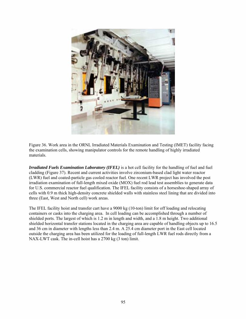
95
Figure 36. Work area in the ORNL Irradiated Materials Examination and Testing (IMET) facility facing the examination cells, showing manipulator controls for the remote handling of highly irradiated materials.
Irradiated Fuels Examination Laboratory (IFEL) is a hot cell facility for the handling of fuel and fuel cladding (Figure 37). Recent and current activities involve zirconium-based clad light water reactor (LWR) fuel and coated-particle gas cooled reactor fuel. One recent LWR project has involved the post irradiation examination of full-length mixed oxide (MOX) fuel rod lead test assemblies to generate data for U.S. commercial reactor fuel qualification. The IFEL facility consists of a horseshoe-shaped array of cells with 0.9 m thick high-density concrete shielded walls with stainless steel lining that are divided into three (East, West and North cell) work areas. The IFEL facility hoist and transfer cart have a 9000 kg (10-ton) limit for off loading and relocating containers or casks into the charging area. In cell loading can be accomplished through a number of shielded ports. The largest of which is 1.2 m in length and width, and a 1.8 m height. Two additional shielded horizontal transfer stations located in the charging area are capable of handling objects up to 16.5 and 36 cm in diameter with lengths less than 2.4 m. A 25.4 cm diameter port in the East cell located outside the charging area has been utilized for the loading of full-length LWR fuel rods directly from a NAX-LWT cask. The in-cell hoist has a 2700 kg (3 ton) limit.
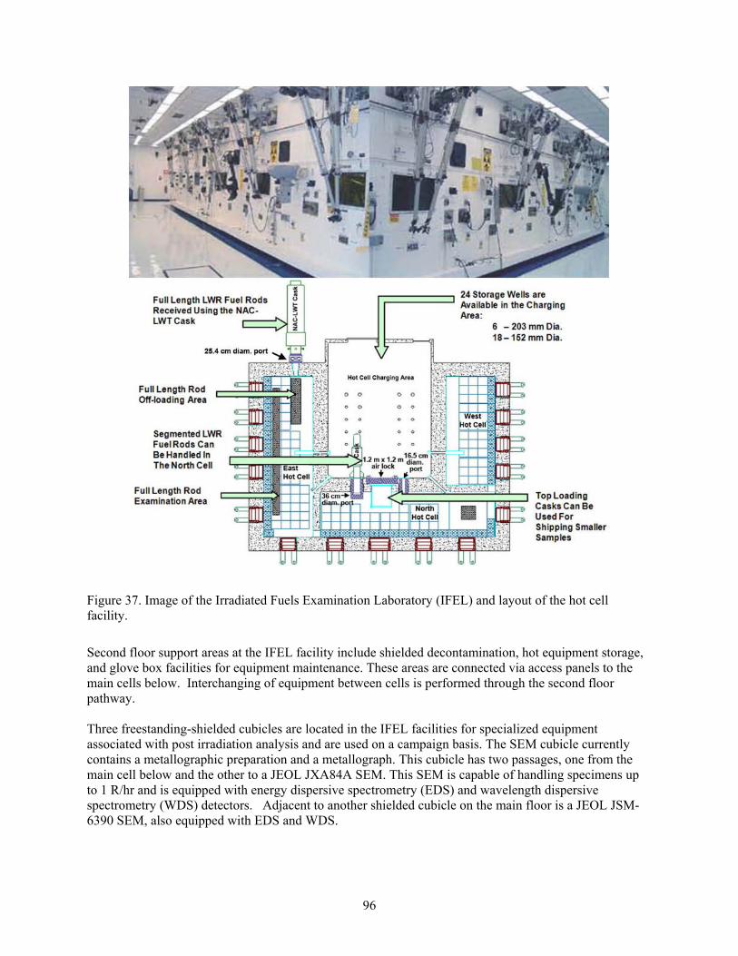
96
Figure 37. Image of the Irradiated Fuels Examination Laboratory (IFEL) and layout of the hot cell facility.
Second floor support areas at the IFEL facility include shielded decontamination, hot equipment storage, and glove box facilities for equipment maintenance. These areas are connected via access panels to the main cells below. Interchanging of equipment between cells is performed through the second floor pathway. Three freestanding-shielded cubicles are located in the IFEL facilities for specialized equipment associated with post irradiation analysis and are used on a campaign basis. The SEM cubicle currently contains a metallographic preparation and a metallograph. This cubicle has two passages, one from the main cell below and the other to a JEOL JXA84A SEM. This SEM is capable of handling specimens up to 1 R/hr and is equipped with energy dispersive spectrometry (EDS) and wavelength dispersive spectrometry (WDS) detectors. Adjacent to another shielded cubicle on the main floor is a JEOL JSM-6390 SEM, also equipped with EDS and WDS.

97
In-cell equipment includes capabilities for remote examination, cutting and machining, metrology, a gamma scanner and metallographic preparation equipment. The IFEL facility also contains contamination zones where further hands-on specimen fabrication and testing can be performed safely on lower activity materials. Transmission electron microscopy (TEM) sample preparation equipment is available in the contamination zone and is capable of thinning specimens to electron transparency by ion milling. Additional information on the IFEL facility and its capabilities can be found through its website (http://www.ms.ornl.gov/NMST/IFEL.shtml). Low Activation Materials Development and Analysis (LAMDA) laboratory is a world-class irradiated materials science facility consisting of four laboratory suites containing specialized instruments for materials testing and characterization (Figure 38). The LAMDA facility allows for the examination of low activity radiological samples (< 60 mR/hr at 30 cm) without the need for remote manipulation. The LAMDA facility is maintained as a low alpha contamination facility (<70 dpm / 100 cm2). This post-irradiation analysis laboratory utilizes small and compact samples to allow researchers to leverage cutting-edge characterization and test equipment not possible through a hot cell facility. Utilization of other ORNL facilities such as the High Temperature Materials Laboratory, Center for Advanced Thin-Film Solar Cells (optical testing) Lab, and ShaRE microscopy facility is also possible on a case-by-case basis for materials handled through LAMDA. Post irradiation examination capabilities in the LAMDA lab are focused on three main categories: mechanical testing, physical properties and microstructural characterization. A wide range of mechanical test frames capable of up to 10 kN loads with test environments to 1800°C and 10‐7 torr vacuum are available, along with impact and microhardness testers. Physical and thermophysical property examinations include densitometers, electrical and thermal conductivity, dilatometry, differential scanning calorimetry and thermal gravimetric analysis. A full complement of equipment for metallographic and microstructural analysis of metallic, ceramic and composite materials is available in the LAMDA facility for optical and electron microscopy. Additional information on the LAMDA facility and its capabilities can be found through its website (http://www.ms.ornl.gov/NMST/LAMDA.shtml).
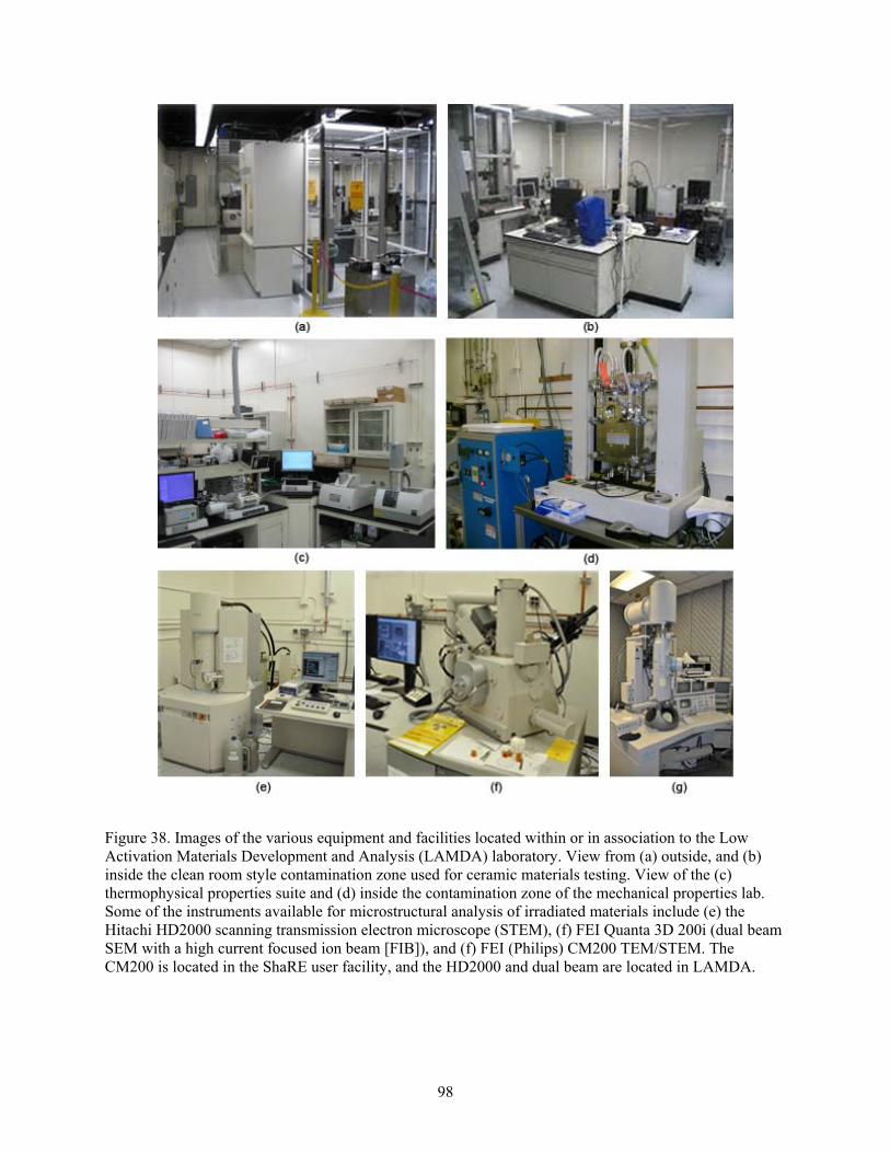
98
Figure 38. Images of the various equipment and facilities located within or in association to the Low Activation Materials Development and Analysis (LAMDA) laboratory. View from (a) outside, and (b) inside the clean room style contamination zone used for ceramic materials testing. View of the (c) thermophysical properties suite and (d) inside the contamination zone of the mechanical properties lab. Some of the instruments available for microstructural analysis of irradiated materials include (e) the Hitachi HD2000 scanning transmission electron microscope (STEM), (f) FEI Quanta 3D 200i (dual beam SEM with a high current focused ion beam [FIB]), and (f) FEI (Philips) CM200 TEM/STEM. The CM200 is located in the ShaRE user facility, and the HD2000 and dual beam are located in LAMDA.
99
Processing of Irradiated Materials for Microstructural Examination Post irradiation microstructural examination of materials is a routine process at ORNL and normally begins with receipt of materials at either the IFEL or IMET hot cell facilities depending on the radiological nature of the shipped material. For samples bearing alpha contamination, receipt of materials and sample preparation would be performed at the IFEL location. If the dose rate of the shipped materials is within limits, direct delivery to LAMDA is possible. For alpha bearing materials, the IFEL facility is capable of all mechanical processing of samples (cutting, mechanical thinning, etc.) into the appropriate specimen sizes either through in-cell remote manipulation or by hand within a contamination zone. In and out-of-cell metallographic polishing are possible for optical and SEM examination. Sample preparation for TEM is performed through ion milling. Recent TEM examination of MOX clad involved the sectioning of fuel rods at IFEL, defueling at the Radiochemical Engineering Development Center and further mechanical processing at IFEL. The rough-cut TEM clad specimens were mechanically polished to remove any fuel/clad interaction layer and chemically leached prior to shipping to LAMDA for electropolishing. Instrument capabilities in LAMDA now include the HD200 STEM that can be used to examine the fuel/clad interface. Bulk material samples above the LAMDA exposure limits that are not alpha emitting, can be processed into smaller size specimens in the IMET facility prior to shipping into LAMDA. Metallographic polishing for optical microscopy and SEM that requires in-cell preparations is generally handled at IFEL. For specimens that do not exceed the 60 mR/hr at 30 cm dose rate, the full capabilities of the LAMDA facility can be utilized. This includes metallographic polishing for optical and SEM examination as well as TEM sample preparation. Depending on the material and the feature to be examined, three processing routes can be utilized for TEM sample preparation. Metallic samples may be processed through electropolishing, while non-conductive ceramics, composites and thin-film samples may be prepared through ion milling techniques. These two conventional TEM sample preparation techniques offer a large area of thinned material for TEM examination. However, if specific areas of interest are to be examined such as grain boundaries, film or metal/oxide interfaces, focused ion beam (FIB) processing may be a more viable procedure. The LAMDA lab has two dual beam (electron and Ga ion) instruments capable of TEM sample fabrication and other micromachining operations. One instrument is designated for the processing of alpha contaminated materials. At this time the instrument is not located in a specialized facility for this work, and therefore there are limits on the sample activity that can be processed. The LAMDA facility also operates a scanning transmission electron microscope (STEM) that is also intended for alpha emitting specimens. This instrument is ideal for chemical analysis work such as solute segregation studies. Expanded analytical TEM capabilities for non-alpha specimens are possible on the FEI CM200 TEM/STEM instrument. A list of the available sample processing equipment and examination instruments at each facility is provided in the following section. Available Equipment and Instruments for Microscopy of Irradiated Materials Irradiated Materials Examination and Testing (IMET) Facility:
General sample processing (cutting and grinding) and photography. FEI Philips XL30 SEM, LaB6 filament; computer-controlled operation, internet-interface
data transfer.

100
Irradiated Fuels Examination Laboratory (IFEL) Facility: General sample processing (cutting and grinding) and photography. Metallographic sample polishing. Optical microscopy. Fischione Model 1010 ion mill, 0.5 - 6 kV extractor voltage, cryogenic milling. JEOL JXA84A SEM, 20 kV, secondary electron (SE) and backscatter electron (BSE)
imaging, energy dispersive (EDS) and wavelength dispersive (WDS) spectrometers. JEOL JSM-6390 SEM, 30 kV, SE- and BSE-imaging, EDS and WDS detectors.
Low Activation Materials Development and Analysis (LAMDA):
General sample processing (cutting and grinding) and photography. Metallographic sample polishing. Keyence Digital Microscope, interchangeable lenses, magnifications from 5 to 5000x,
polarizer. Fischione Model 1010 ion mill, 0.5 - 6 kV extractor voltage, cryogenic milling. Top Con 510 SEM, SE and BSE imaging, EDS detector. Hitachi 4700 SEM, field emission gun (FEG), SE and BSE imaging, EDS detector
(available soon). Two, FEI Quanta 3D 200i Dual Beam (Focused Ion Beam Milling), 200V-30kV electron optics <
4 nm resolution at 30 kV. 2kV-30kV ion optics with 9 nm resolution at 30 kV. Variable pressure chamber operations.
Technoorg Linda Gentle Mill: 100-2kV ion mill, post FIB sample cleaning system. Hitachi HD2000 Scanning Transmission Electron Microscope (STEM): 200 kV FEG, high-
resolution secondary and High Angle Annular Dark Field (HAADF) detector (Z-contrast) imaging, EDS.
FEI CM200 Transmission Electron Microscope: 200 kV FEG, High-resolution STEM, EDS, HAADF detector, post-column Gatan image filter (EFTEM and EELS). Instrument is a co-ownership with ShaRE program.
Additional instruments are also available through the Shared Research Equipment (ShaRE) User Facility (http://www.ornl.gov/sci/share/).

101
Appendix D – Example As-Built Data Package Worksheets and Checklists
Example Process Worksheet (PWS)
INL Item ID #:________________________ Vendor Item ID #:_______________________ Sheet ____ of _____
Pre‐Processing and Braiding
Braided By: Ply / Weave
Mass (g)
ID (in) OD (in) Length (in)
SiC Fiber Lot ID
Notes/Meas. Devices:
Date: Recorded By:
PIP/Pyrocarbon Processing Steps Step #
Step Details Polymer Lot:
Temp (ºF)
% Rel Humid.
Mass (g) Scale ID:
Notes/Meas. Devices: Location: Performer/Date:
Notes/Meas. Devices: Location: Performer/Date:
Final Report
Go‐No‐Go Check
Mass (g) Approx ID (in)
Approx OD (in)
Length (in)
Notes:
ID:
OD: Device ID:
Density: Recorded By: Date:
--------- Properly bag, label, and stow materials when not in process

102
Example As-Built Data Package Checklist Included Requirement Data Source Origin Quality Engineer
(Date/initials) □ Polymer and other PyC and PIP process
material certifications
□ Process Work Sheet(s) Includes the following:
- Braiding Info - PIP Process Info - Dimensional Inspection - Final Inspection
□ Photos of braided tubes □ Photos of tubes mid process and final □ Calibration Documents □ Listing of Measurement Devices Used
- Record when each device was used (step # or other details)
□ Final Product List □ Final inspection of shipping packages □ □ □ □
As built data package to include all items listed in checklist. For polymer and other PYC and PIP process materials, provide the material name, manufacturer, lot IDs, and other data for identification and traceability purposes.