LIGHT SCREENSSAFETY Safety Light Screens - …* For an emitter with TEST function, replace Q8 with...
68
17 More information online at bannerengineering.com SAFETY LIGHT SCREENS SAFETY LIGHT SCREENS Safety Light Screens EZ-SCREEN ® . . . . . . . . . . . . . . . . . . . . . . . .page 20 • Provides point-of-operation, area, access and perimeter safeguarding. • Protects personnel from injury and equipment from damage. • Offered with 14 and 30 mm resolution, single-beam points, or multi-beam grids. • Requires no controller. • Rated Type 4. • Available with optional ESD-safe housing, pigtail connectors and cascading on some models. • Reduced resolution and fixed blanking on EZ-SCREEN Type 4. MINI-SCREEN ® . . . . page 58 • Suitable for heavy-duty machine guarding applications—extra robust housing available. • Features rugged, compact emitters and receivers ranging from 114 to 1829 mm long, depending on series and model. • Includes floating blanking and selectable auto power-up. • Offers optional fixed-beam blanking and muting. • Offered with yellow or black housing on emitters and receivers. PICO-GUARD ™ . . . . . . . . . . . . . . . . . . . . . . . . . . . . . . . . . . . . . . . . . . . . . page 36 • Provides access and short-range perimeter guarding. • Offers low-cost alternative to cumbersome machine guarding methods. • Combines fiber optic and photoelectric technologies. • Uses fiber optic technology for intrinsically safe guarding in explosive or harsh environments. • Installs easily using inexpensive plastic fiber optics. MICRO-SCREEN ® . . . . . . . . . . . . . . . . . . . . . . . . . . . . . . . . . . . . . . . . . . . page 42 • Designed for light- to medium-duty production machinery. • Features ultra-compact emitters and receivers ranging from 102 to 1829 mm long, depending on series and model. • Offered with optional ESD-safe housing. • Includes floating blanking and optional fixed blanking. • Controllers offered with DeviceNet ™ , E-stop input and muting. EZ-SCREEN ® Type 2 . page 78 • Designed for lower-risk applications. • Provides economical, compact optical safeguarding. • Meets Type 2 requirements per IEC 61496-1/-2. • Offered with 30 mm resolution and 15 m range.
Transcript of LIGHT SCREENSSAFETY Safety Light Screens - …* For an emitter with TEST function, replace Q8 with...

17More information online at bannerengineering.com
SAFETY LIGHT SCREENSSA
FETYLIG
HT SC
REEN
S
Safety Light ScreensEZ-SCREEN® . . . . . . . . . . . . . . . . . . . . . . . .page 20
• Provides point-of-operation, area, access and perimeter safeguarding.
• Protects personnel from injury and equipment from damage. • Offered with 14 and 30 mm resolution, single-beam points,
or multi-beam grids.• Requires no controller.• Rated Type 4.• Available with optional ESD-safe housing, pigtail connectors
and cascading on some models.• Reduced resolution and fixed blanking on EZ-SCREEN Type 4.
MINI-SCREEN® . . . . page 58• Suitable for heavy-duty machine guarding
applications —extra robust housing available.
• Features rugged, compact emitters and receivers ranging from 114 to 1829 mm long, depending on series and model.
• Includes floating blanking and selectable auto power-up.
• Offers optional fixed-beam blanking and muting.
• Offered with yellow or black housing on emitters and receivers.
PICO-GUARD™ . . . . . . . . . . . . . . . . . . . . . . . . . . . . . . . . . . . . . . . . . . . . . page 36• Provides access and short-range perimeter guarding.• Offers low-cost alternative to cumbersome machine guarding methods.• Combines fiber optic and photoelectric technologies.• Uses fiber optic technology for intrinsically safe guarding in explosive or harsh environments.• Installs easily using inexpensive plastic fiber optics.
MICRO-SCREEN® . . . . . . . . . . . . . . . . . . . . . . . . . . . . . . . . . . . . . . . . . . . page 42• Designed for light- to medium-duty production machinery.• Features ultra-compact emitters and receivers ranging from 102 to 1829 mm long, depending on series and model.• Offered with optional ESD-safe housing.• Includes floating blanking and optional fixed blanking.• Controllers offered with DeviceNet™, E-stop input and muting.
EZ-SCREEN® Type 2 . page 78• Designed for lower-risk applications.• Provides economical, compact optical
safeguarding.• Meets Type 2 requirements per
IEC 61496-1/-2.• Offered with 30 mm resolution and
15 m range.

18 More information online at bannerengineering.com
SAFETY LIGHT SCREENSSA
FETY
LIG
HT
SCR
EEN
S
Catalog Safety Supply Maximum Type Model Page Category Resolution Voltage Range
SA
FE
TY L
IGH
T S
CR
EE
N S
EL
EC
TIO
NEZ
-SCR
EEN
®Standard Systems
Page 20 4
14 & 30 mm
24V dc
18 m
Cascade Systems 14 & 30 mm 18 m
Grid & Point Systems 300 to 584 mm(beam spacing)
70 m
PICO
-GU
ARD
™ Grid Systems
Page 36 4
300 to 584 mm(beam spacing)
24V dc 31 m
Point Systems —
MIC
RO-S
CREE
N®
Emitters & Receivers
Page 42 4
19 mmSupplied
bycontroller
9 mStandard Series
32 mmV-Series
Controllers
N/A
24V dc,115 or
230V acN/A
Metal Box Controllers
24V dcDIN Module Controllers
MIN
I-SC
REE
N®
Emitters & Receivers
Page 58 4
19 & 25 mmSupplied
bycontroller
18 mStandard Series
38 mmHeavy-Duty Series
Controllers
N/A
24V dc, 115V ac
or230V ac N/A
Metal Box Controllers
24V dcDIN Module Controllers
EZ-S
CREE
N® T
ype
2
Type 2 Systems Page 78 2 30 mm 24V dc 15 m
NC = Normally Closed Relay, NO = Normally Open Relay

19More information online at bannerengineering.com
SAFETY LIGHT SCREENSSA
FETYLIG
HT SC
REEN
S
Safety Muting Output Housing EnvironmentalOutput Blanking Option Response Time Material Rating
2 PNPOSSD
(Trip /LatchSelectable)
Reduced Resolution(floating)2-beam
&Fixed
OptionalAccessory
(see page 123)
9 to 56 ms
Aluminum housing with yellow polyester
powder finish or nickel-plated ESD
IEC IP6511 to 56 ms
— ≤ 24 ms
2 PNPOSSD
(Trip /LatchSelectable)
See page 108for controller
—Optional
Accessory(see page 123)
13 ms
See page 108 for controller
Black aluminum housing,tempered glass window IEC IP65
12 mm threaded barrel: Black polycarbonate plastic housing30 mm threaded barrel: Stainless steel housing, glass window.
IEC IP67
—
Reduced Resolution(floating)
1- or 2-beam&
Fixed
—
< 38 ms(< 48 ms for
muting)
Aluminum housing with yellow polyester
powder finish or
nickel-plated ESD
IEC IP65
2 NO(Trip or Latch) Yes Welded steel box with black
polyester powder paint finish IEC IP64
2 or 4 NO(Trip or Latch)
OptionalAccessory
(see page 123)Gray polycarbonate IEC IP20
—
Reduced Resolution(floating)
1- or 2-beam&
Fixed
—
< 48 to < 72 ms(< 58 to < 82 ms
for muting)
Aluminum housing with black anodized or
yellow polyester painted finishIEC IP65
2 NO(Trip or Latch)
Yes Welded steel box with black polyester powder paint finish IEC IP64
OptionalAccessory
(see page 123)Gray polycarbonate IEC IP20
2 PNPOSSD
(Trip or Latch)—
OptionalAccessory
(see page 123)11 to 25 ms
Aluminum housing with yellow polyester
powder finishIEC IP65

20 More information online at bannerengineering.com
EZ-SCREEN®
PICO-GUARD™
MICRO-SCREEN®
MINI-SCREEN®
SAFE
TYLI
GH
T SC
REE
NS
EZ-SCREEN® TYPE 2
14 mm Resolution Models . . . . . . . . . . . . Page 2130 mm Resolution Models . . . . . . . . . . . . . . . . . 22Cascade Systems . . . . . . . . . . . . . . . . . . . . . . . . 2414 and 30 mm Interfacing Products. . . . . . . . . . 2614 and 30 mm Resolution Kits . . . . . . . . . . . . . . 27Grid and Point Models . . . . . . . . . . . . . . . . . . 28Grid and Point Interfacing Products . . . . . . . . . . 30Grid Kits . . . . . . . . . . . . . . . . . . . . . . . . . . . . . . . 31Point Kits . . . . . . . . . . . . . . . . . . . . . . . . . . . . . . 32
EZ-SCREEN® Systems
SAFETY LIGHT SCREENS
EZ-SCREEN® Safety Light Screens
• Simple, two-piece integrated system has no control box.• High-resolution 14 and 30 mm EZ-SCREEN® point-of-operation
systems provide finger, hand and ankle detection.• EZ-SCREEN Point and Grid systems allow one-, two-, three-
or four-beam perimeter and access guarding. • Superior optical design and finely focused ±2.5° beam make
systems extremely easy to align and maintain. • Status indicators and diagnostics show when alignment is
complete and if there are problems with the installation. • Redundant microprocessor-controlled, self-checking
design exceeds control reliability requirements and iscertified per CE (Type 4/Category 4) and cULus (NIPF,UL 61496, UL 1998).
• Unique cascading models (patent-pending) allow up to four systems of any length and resolution to be wired together to form a single safety device.
• Systems have ranges up to 70 m, with power and range for all types of applications including long-range perimeter guarding.
Point of operation.• Finger, hand or
ankle detection at the point of operation.
• Use 14 or 30 mmEZ-SCREEN.
Area.• Mount horizontally
to eliminate safety mats and area scanners.
• Manually reset Latch output when area is clear.
Perimeter.• Guard mulitple
sides of a dangerous areaup to 70 m long.
• Expand guarding with optional corner mirrors and mounting stands.
Long-range single sided.• EZ-SCREEN Grid
systems provide2, 3 or 4 beams.
• Beam spacingis from 300 to 584 mm.
Single point access.• Use with angled
mirrors to simulate a 2-beam system.
• Use multiple units for custom beam patterns.
ESD applications.• Dissipate
electrostatic discharges.
• Ideal for microelectronic applications.
A complete family of machine guarding products.
QD CABLES
PAGE 176
PAGE 187
PAGE204
PAGE209
PAGE213
PAGE216
8-Pin Euro + 3- & 8-Pin Mini
BRACKETS
PAGE 190

EZ-SCREEN® Systems
21More information online at bannerengineering.com
SAFETY LIGHT SCREENS
EZ-SCREEN®
PICO-GUARD™
MICRO-SCREEN®
MINI-SCREEN®
SAFETY
LIGH
T SCR
EENS
EZ-SCREEN ®TYPE 2
EZ-SCREEN® Systems, 14 mm Resolution
Models* Resolution RangeDefined
AreaHousing
Length (L)SupplyVoltage
SafetyOutputs
Response Time
Connec-tion**
Data Sheet
SLSP14-150Q88†
14 mm Resolution
0.1 to 6 m
150 mm 262 mm
24V dc 2 PNPOSSD
≤ 11 ms
8-pin Euro QD 112852
SLSE14-150Q8SLSR14-150Q8
SLSP14-300Q88†
300 mm 372 mm ≤ 15 msSLSE14-300Q8SLSR14-300Q8
SLSP14-450Q88†
450 mm 522 mm ≤ 19 msSLSE14-450Q8SLSR14-450Q8
SLSP14-600Q88†
600 mm 671 mm ≤ 23 msSLSE14-600Q8SLSR14-600Q8
SLSP14-750Q88†
750 mm 821 mm ≤ 27 msSLSE14-750Q8SLSR14-750Q8
SLSP14-900Q88†
900 mm 971 mm ≤ 32 msSLSE14-900Q8SLSR14-900Q8
SLSP14-1050Q88†
1050 mm 1120 mm ≤ 36 msSLSE14-1050Q8SLSR14-1050Q8
7-segment diagnostic display
Blocked beam zone indicators
System status and system reset status
Integral or pigtail Euro-style QD connection
Durable aluminum housing to resist twisting
Metal end caps for added durability
User configurable trip or latch outputs and Scan Code 1 or 2
Fixed or 2-beam reduced resolution (floating) blanking
EDM input and optional TEST** function
EZ-SCREEN® Systems
EZ-SCREEN Systems
DetailedDimensions
45.0 mm
L
36.0 mm
Full View ofAvailable Finishes
Yellow Painted Aluminum
Nickel-PlatedESD
DownloadPDF
14 mm Resolution* Nickel-plated emitters and receivers used for ESD safe applications are available by adding “N” in the model number (example, SLSE14-150NQ8).** For an emitter with TEST function, replace Q8 with Q5 on emitter model numbers (example, SLSE14-150Q5) and Q88 with Q85 on pair model numbers
(example, SLSP14-150Q85). For a 300 mm Euro pigtail QD, replace “Q” with “P” in models numbers (example, SLSP14-150P88). A model with a QD requires a mating cable (see page 176).
† A pair includes an emitter and receiver (example, SLSP14-150Q88). Emitters (example, SLSE14-150Q8) and receivers (example, SLSR14-150Q8) are also sold separately.

22 More information online at bannerengineering.com
SAFETY LIGHT SCREENSEZ-SCREEN® Systems
EZ-SCREEN®
PICO-GUARD™
MICRO-SCREEN®
MINI-SCREEN®
SAFE
TYLI
GH
T SC
REE
NS
EZ-SCREEN® TYPE 2
EZ-SCREEN® Systems, 14 mm Resolution
Models* Resolution RangeDefined
AreaHousing
Length (L)SupplyVoltage
SafetyOutputs
Response Time
Connec-tion**
Data Sheet
SLSP14-1200Q88†
14 mm Resolution
0.1 to 6 m
1200 mm 1270 mm
24V dc 2 PNPOSSD
≤ 40 ms
8-pin Euro QD 112852
SLSE14-1200Q8SLSR14-1200Q8
SLSP14-1350Q88†
1350 mm 1420 mm ≤ 43 msSLSE14-1350Q8SLSR14-1350Q8
SLSP14-1500Q88†
1500 mm 1569 mm ≤ 48 msSLSE14-1500Q8SLSR14-1500Q8
SLSP14-1650Q88†
1650 mm 1719 mm ≤ 52 msSLSE14-1650Q8SLSR14-1650Q8
SLSP14-1800Q88†
1800 mm 1869 mm ≤ 56 msSLSE14-1800Q8SLSR14-1800Q8
EZ-SCREEN® Systems, 30 mm Resolution
Models* Resolution RangeDefined
AreaHousing
Length (L)SupplyVoltage
SafetyOutputs
Response Time
Connec-tion**
Data Sheet
SLSP30-150Q88†
30 mm Resolution
0.1 to 18 m
150 mm 262 mm
24V dc 2 PNPOSSD
≤ 9 ms
8-pin Euro QD 112852
SLSE30-150Q8SLSR30-150Q8
SLSP30-300Q88†
300 mm 372 mm ≤ 11 msSLSE30-300Q8SLSR30-300Q8
SLSP30-450Q88†
450 mm 522 mm ≤ 13 msSLSE30-450Q8SLSR30-450Q8
SLSP30-600Q88†
600 mm 671 mm ≤ 15 msSLSE30-600Q8SLSR30-600Q8
SLSP30-750Q88†
750 mm 821 mm ≤ 17 msSLSE30-750Q8SLSR30-750Q8
14 mm Resolution 30 mm Resolution* Nickel-plated emitters and receivers used for ESD safe applications are available by adding “N” in the model number (example, SLSE14-1200NQ8).** For an emitter with TEST function, replace Q8 with Q5 on emitter model numbers (example, SLSE14-1200Q5) and Q88 with Q85 on pair model numbers
(example, SLSP14-1200Q85). For a 300 mm Euro pigtail QD, replace “Q” with “P” in models numbers (example, SLSP14-1200P88). A model with a QD requires a mating cable (see page 176).
† A pair includes an emitter and receiver (example, SLSP14-1200Q88). Emitters (example, SLSE14-1200Q8) and receivers (example, SLSR14-1200Q8) are also sold separately.
DownloadPDF
DownloadPDF
(cont’d)

EZ-SCREEN® Systems
23More information online at bannerengineering.com
SAFETY LIGHT SCREENS
EZ-SCREEN®
PICO-GUARD™
MICRO-SCREEN®
MINI-SCREEN®
SAFETY
LIGH
T SCR
EENS
EZ-SCREEN ®TYPE 2
EZ-SCREEN® Systems, 30 mm Resolution
Models* Resolution RangeDefined
AreaHousing
Length (L)SupplyVoltage
SafetyOutputs
Response Time
Connec-tion**
Data Sheet
SLSP30-900Q88†
30 mm Resolution
0.1 to 18 m
900 mm 971 mm
24V dc 2 PNPOSSD
≤ 19 ms
8-pin Euro QD 112852
SLSE30-900Q8SLSR30-900Q8
SLSP30-1050Q88†
1050 mm 1120 mm ≤ 21 msSLSE30-1050Q8SLSR30-1050Q8
SLSP30-1200Q88†
1200 mm 1270 mm ≤ 23 msSLSE30-1200Q8SLSR30-1200Q8
SLSP30-1350Q88†
1350 mm 1420 mm ≤ 25 msSLSE30-1350Q8SLSR30-1350Q8
SLSP30-1500Q88†
1500 mm 1569 mm ≤ 27 msSLSE30-1500Q8SLSR30-1500Q8
SLSP30-1650Q88†
1650 mm 1719 mm ≤ 30 msSLSE30-1650Q8SLSR30-1650Q8
SLSP30-1800Q88†
1800 mm 1869 mm ≤ 32 msSLSE30-1800Q8SLSR30-1800Q8
30 mm Resolution* Nickel-plated emitters and receivers used for ESD safe applications are available by adding “N” in the model number (example, SLSE30-900NQ8).** For an emitter with TEST function, replace Q8 with Q5 on emitter model numbers (example, SLSE30-900Q5) and Q88 with Q85 on pair model numbers
(example, SLSP30-900Q85). For a 300 mm Euro pigtail QD, replace “Q” with “P” in models numbers (example, SLSP30-900P88). A model with a QD requires a mating cable (see page 176).
† A pair includes an emitter and receiver (example, SLSP30-900Q88). Emitters (example, SLSE30-900Q8) and receivers (example, SLSR14-900Q8) are also sold separately.
DownloadPDF
(cont’d)

24 More information online at bannerengineering.com
SAFETY LIGHT SCREENSEZ-SCREEN® Systems
EZ-SCREEN®
PICO-GUARD™
MICRO-SCREEN®
MINI-SCREEN®
SAFE
TYLI
GH
T SC
REE
NS
EZ-SCREEN® TYPE 2
EZ-SCREEN® Cascade Systems, 14 mm Resolution
Models* Resolution RangeDefined
AreaHousing
Length (L)SupplyVoltage
SafetyOutputs
Response Time**
Connec-tion***
Data Sheet
SLSCP14-300Q88†
14 mm Resolution
0.1 to 6 m
300 mm 372 mm
24V dc 2 PNPOSSD
≤ 15 ms
8-pin Euro QD 112852
SLSCE14-300Q8SLSCR14-300Q8
SLSCP14-450Q88†
450 mm 522 mm ≤ 19 msSLSCE14-450Q8SLSCR14-450Q8
SLSCP14-600Q88†
600 mm 671 mm ≤ 23 msSLSCE14-600Q8SLSCR14-600Q8
SLSCP14-750Q88†
750 mm 821 mm ≤ 27 msSLSCE14-750Q8SLSCR14-750Q8
SLSCP14-900Q88†
900 mm 971 mm ≤ 32 msSLSCE14-900Q8SLSCR14-900Q8
SLSCP14-1050Q88†
1050 mm 1120 mm ≤ 36 msSLSCE14-1050Q8SLSCR14-1050Q8
SLSCP14-1200Q88†
1200 mm 1270 mm ≤ 40 msSLSCE14-1200Q8SLSCR14-1200Q8
SLSCP14-1350Q88†
1350 mm 1420 mm ≤ 43 msSLSCE14-1350Q8SLSCR14-1350Q8
SLSCP14-1500Q88†
1500 mm 1569 mm ≤ 48 msSLSCE14-1500Q8SLSCR14-1500Q8
SLSCP14-1650Q88†
1650 mm 1719 mm ≤ 52 msSLSCE14-1650Q8SLSCR14-1650Q8
SLSCP14-1800Q88†
1800 mm 1869 mm ≤ 56 msSLSCE14-1800Q8SLSCR14-1800Q8
14 mm Resolution * Nickel-plated emitters and receivers used for ESD safe applications are available by adding “N” in the model number (example, SLSCE14-300NQ8).** Cascading system response time: To the response time of the slowest pair, add 2 ms for each additional pair. Example: slowest pair’s response time is 15 ms, and the
system has three additional pairs (four pairs total), so the system maximum response time is 15 ms + 6 ms (3 pairs x 2 ms) = 21 ms.*** For an emitter with TEST function, replace Q8 with Q5 on emitter model numbers (example, SLSCE14-300Q5) and Q88 with Q85 on pair model numbers
(example, SLSCP14-300Q85). For a 300 mm Euro pigtail QD, replace “Q” with “P” in models numbers (example, SLSCP14-300P88). A model with a QD requires a mating cable (see page 176).
† A pair includes an emitter and receiver (example, SLSCP14-300Q88). Emitters (example, SLSCE14-300Q8) and receivers (example, SLSCR14-300Q8) are also sold separately.
DownloadPDF

EZ-SCREEN® Systems
25More information online at bannerengineering.com
SAFETY LIGHT SCREENS
EZ-SCREEN®
PICO-GUARD™
MICRO-SCREEN®
MINI-SCREEN®
SAFETY
LIGH
T SCR
EENS
EZ-SCREEN ®TYPE 2
EZ-SCREEN® Cascade Systems, 30 mm Resolution
Models* Resolution RangeDefined
AreaHousing
Length (L)SupplyVoltage
SafetyOutputs
Response Time**
Connec-tion***
Data Sheet
SLSCP30-300Q88†
30 mm Resolution
0.1 to 18 m
300 mm 372 mm
24V dc 2 PNPOSSD
≤ 11 ms
8-pin Euro QD 112852
SLSCE30-300Q8SLSCR30-300Q8
SLSCP30-450Q88†
450 mm 522 mm ≤ 13 msSLSCE30-450Q8SLSCR30-450Q8
SLSCP30-600Q88†
600 mm 671 mm ≤ 15 msSLSCE30-600Q8SLSCR30-600Q8
SLSCP30-750Q88†
750 mm 821 mm ≤ 17 msSLSCR30-750Q8SLSCR30-750Q8
SLSCP30-900Q88†
900 mm 971 mm ≤ 19 msSLSCE30-900Q8SLSCR30-900Q8
SLSCP30-1050Q88†
1050 mm 1120 mm ≤ 21 msSLSCE30-1050Q8SLSCR30-1050Q8
SLSCP30-1200Q88†
1200 mm 1270 mm ≤ 23 msSLSCE30-1200Q8SLSCR30-1200Q8
SLSCP30-1350Q88†
1350 mm 1420 mm ≤ 25 msSLSCE30-1350Q8SLSCR30-1350Q8
SLSCP30-1500Q88†
1500 mm 1569 mm ≤ 27 msSLSCE30-1500Q8SLSCR30-1500Q8
SLSCP30-1650Q88†
1650 mm 1719 mm ≤ 30 msSLSCE30-1650Q8SLSCR30-1650Q8
SLSCP30-1800Q88†
1800 mm 1869 mm ≤ 32 msSLSCE30-1800Q8SLSCR30-1800Q8
30 mm Resolution * Nickel-plated emitters and receivers used for ESD safe applications are available by adding “N” in the model number (example, SLSCE30-300NQ8).** Cascading system response time: To the response time of the slowest pair, add 2 ms for each additional pair. Example: slowest pair’s response time is 15 ms, and the
system has three additional pairs (four pairs total), so the system maximum response time is 15 ms + 6 ms (3 pairs x 2 ms) = 21 ms.*** For an emitter with TEST function, replace Q8 with Q5 on emitter model numbers (example, SLSCE30-300Q5) and Q88 with Q85 on pair model numbers
(example, SLSCP30-300Q85). For a 300 mm Euro pigtail QD, replace “Q” with “P” in models numbers (example, SLSCP30-300P88). A model with a QD requires a mating cable (see page 176).
† A pair includes an emitter and receiver (example, SLSCP30-300Q88). Emitters (example, SLSCE30-300Q8) and receivers (example, SLSCR30-300Q8) are also sold separately.
DownloadPDF
26 More information online at bannerengineering.com
SAFETY LIGHT SCREENSEZ-SCREEN® Systems
EZ-SCREEN®
PICO-GUARD™
MICRO-SCREEN®
MINI-SCREEN®
SAFE
TYLI
GH
T SC
REE
NS
EZ-SCREEN® TYPE 2
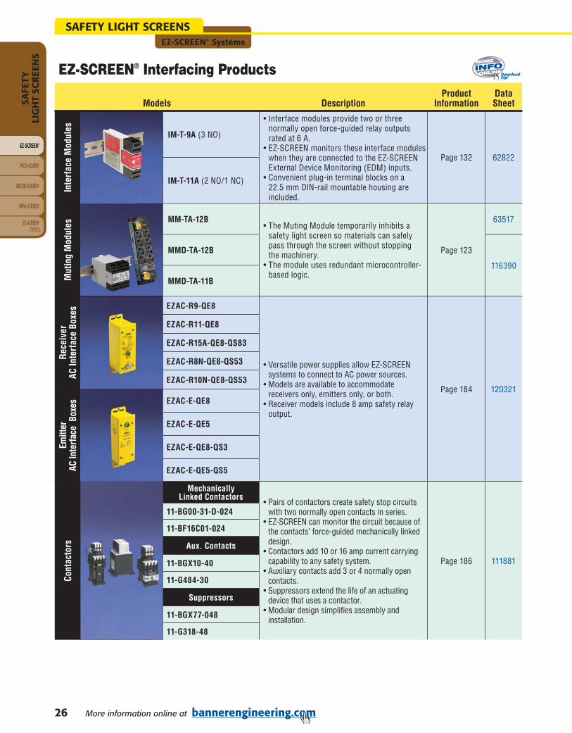
EZ-SCREEN® Interfacing Products
Models DescriptionProduct
InformationDataSheet
Inte
rfac
e M
odul
es
IM-T-9A (3 NO)
• Interface modules provide two or three normally open force-guided relay outputs rated at 6 A.
• EZ-SCREEN monitors these interface modules when they are connected to the EZ-SCREEN External Device Monitoring (EDM) inputs.
• Convenient plug-in terminal blocks on a 22.5 mm DIN-rail mountable housing are included.
Page 132 62822
IM-T-11A (2 NO/1 NC)
Mut
ing
Mod
ules MM-TA-12B
• The Muting Module temporarily inhibits a safety light screen so materials can safely pass through the screen without stopping the machinery.
• The module uses redundant microcontroller-based logic.
Page 123
63517
MMD-TA-12B
116390
MMD-TA-11B
Rece
iver
AC
Inte
rfac
e Bo
xes EZAC-R9-QE8
• Versatile power supplies allow EZ-SCREEN systems to connect to AC power sources.
• Models are available to accommodate receivers only, emitters only, or both.
• Receiver models include 8 amp safety relay output.
Page 184 120321
EZAC-R11-QE8
EZAC-R15A-QE8-QS83
EZAC-R8N-QE8-QS53
EZAC-R10N-QE8-QS53
Emitt
er
AC In
terfa
ce B
oxes EZAC-E-QE8
EZAC-E-QE5
EZAC-E-QE8-QS3
EZAC-E-QE5-QS5
Cont
acto
rs
MechanicallyLinked Contactors
• Pairs of contactors create safety stop circuits with two normally open contacts in series.
• EZ-SCREEN can monitor the circuit because of the contacts’ force-guided mechanically linked design.
• Contactors add 10 or 16 amp current carrying capability to any safety system.
• Auxiliary contacts add 3 or 4 normally open contacts.
• Suppressors extend the life of an actuating device that uses a contactor.
• Modular design simplifies assembly and installation.
Page 186 111881
11-BG00-31-D-024
11-BF16C01-024
Aux. Contacts
11-BGX10-40
11-G484-30
Suppressors
11-BGX77-048
11-G318-48
DownloadPDF

EZ-SCREEN® Systems
27More information online at bannerengineering.com
SAFETY LIGHT SCREENS
EZ-SCREEN®
PICO-GUARD™
MICRO-SCREEN®
MINI-SCREEN®
SAFETY
LIGH
T SCR
EENS
EZ-SCREEN ®TYPE 2
You can purchase a kit that contains an emitter and receiver of equal length and resolution; brackets; and optional interfacing solution and quick-disconnect cables. Detailed information about individual kit components is as follows.
• Emitter and Receivers . . . . . . . . . . . . . . . . . . . . . . . . . . . . . . . . . .Page 21• Interfacing Options . . . . . . . . . . . . . . . . . . . . . . . . . . . . . . . . . . . . . . . . 26• Cables . . . . . . . . . . . . . . . . . . . . . . . . . . . . . . . . . . . . . . . . . . . . . . . . . 176• Brackets . . . . . . . . . . . . . . . . . . . . . . . . . . . . . . . . . . . . . . . . . . . . . . . . 190
A partial listing of kits is listed below; see Kit Model Key to order other variations.
EZ-SCREEN® 14 & 30 mm Resolution Kits
Kit Model Number
SLSK14-600Q88-1RE25•
No
600 mm
14 mm 6 m
24V dc 2 OSSD
Trip/Latch
Select-able
Integral Euro QDwithout
Test
IM-T-9A, 1 each
8 m, 2 each
SLSK30-600Q88-1RE25 30 mm 18 m
SLSK14-600NQ88-1RE25•
14 mm 6 m
SLSK30-600NQ88-1RE25 30 mm 18 m
SLSCK14-600Q88-1RE25•
Yes*
14 mm 6 m
SLSCK30-600Q88-1RE25 30 mm 18 m
SLSCK14-600NQ88-1RE25•
14 mm 6 m
SLSCK30-600NQ88-1RE25 30 mm 18 m
* For cascading systems, order one kit; up to three additional emitter/receiver pairs; and two double-ended cables per additional emitter/receiver pair. Opposed pairs must be the same length and resolution (see page 24).
SensorHousing
Casc
adin
g
Prot
ecte
d H
eigh
t
Res
olut
ion
Ran
ge
Supp
ly
Volt
age
No.
of
Out
puts
Out
put
Opt
ions
Emit
ter
&
Rec
eive
rCo
nnec
tion
Inte
rfac
ing
Opt
ions
QD
Cab
ling
YellowNickel-Plated
Model StyleSLS = Safety Light ScreenSLSC = Cascading Safety
Light Screen
Model Style
1 4S L S K 1 R E 2 5
Kit Resolution ProtectedHeight
QD Options Interfacing Options
QD CablingLength Options
SLS Resolution14 = 14 mm30 = 30 mm
KitK = Kit
Protected Height150 mm300 mm450 mm600 mm750 mm900 mm
1050 mm1200 mm1350 mm1500 mm1650 mm1800 mm
NOTE: Not all combinations are possible. Contact Banner Engineering Corp. for additional information and/or verification of valid kit model numbers.
Receiver & Emitter QD Options
Q85 = Receiver with integral 8-pin Euro-style QD Emitter with integral 5-pin Euro-style QD with Test
Q88 = Receiver with integral 8-pin Euro-style QD Emitter with integral 8-pin Euro-style QD
P85 = Receiver with integral 8-pin Euro-style pigtail QD Emitter with integral 5-pin Euro-style pigtail QD with Test
P88 = Receiver with integral 8-pin Euro-style pigtail QD Emitter with integral 8-pin Euro-style pigtail QD
Interfacing Options1 = IM-T-9A Interface Module, 1 each2 = IM-T-11A Interface Module, 1 each3 = 11-BG00-31-D-024 Contactors (10A), 2 each4 = 11-BF16C01-024 Contactors (16A), 2 each5 = EZAC-R9-QE8 = AC Interface Box (3 NO), 1 each6 = EZAC-R11-QE8 = AC Interface Box (2 NO/1 NC), 1 each
QD Cabling Length OptionsRE15 = 5 m, 2 eachRE25 = 8 m, 2 eachR15E25 = 5 m (Receiver) & 8 m (Emitter)R25E15 = 8 m (Receiver) & 5 m (Emitter)RE50 = 15 m, 2 eachR15E50 = 5 m (Receiver) & 15 m (Emitter)R50E15 = 15 m (Receiver) & 5 m (Emitter)R25E50 = 8 m (Receiver) & 15 m (Emitter)R50E25 = 15 m (Receiver) & 8 m (Emitter)RE75 = 23 m, 2 eachRE100 = 30 m, 2 each
6 0 0
Finish
Sensor FinishBlank = Yellow powder coatN = Nickel plated ESD
Q 8 8
Kit Model Key

28 More information online at bannerengineering.com
SAFETY LIGHT SCREENSEZ-SCREEN® Systems
EZ-SCREEN®
PICO-GUARD™
MICRO-SCREEN®
MINI-SCREEN®
SAFE
TYLI
GH
T SC
REE
NS
EZ-SCREEN® TYPE 2
EZ-SCREEN® Grid & Point Systems
ModelsBeam
Spacing RangeProtected
HeightHousing
Length (L)SupplyVoltage
SafetyOutputs
Response Time Connection*
Data Sheet
SGP4-300Q83†
300 mm
0.8to
20 m
900 mm 1084 mm
24V dc 2 PNPOSSD ≤ 24 ms
Emitter, 3-pin Mini QDReceiver, 8-pin Mini QD
68410
SGE4-300Q3 3-pin Mini QD
SGR4-300Q8 8-pin Mini QD
SGXLP4-300Q83†
15to
70 m
Emitter, 3-pin Mini QDReceiver, 8-pin Mini QD
SGXLE4-300Q3 3-pin Mini QD
SGR4-300Q8 8-pin Mini QD
SGP3-400Q83†
400 mm
0.8to
20 m
800 mm 984 mm
Emitter, 3-pin Mini QDReceiver, 8-pin Mini QD
SGE3-400Q3 3-pin Mini QD
SGR3-400Q8 8-pin Mini QD
SGXLP3-400Q83†
15to
70 m
Emitter, 3-pin Mini QDReceiver, 8-pin Mini QD
SGXLE3-400Q3 3-pin Mini QD
SGR3-400Q8 8-pin Mini QD
One to four beam models for access or perimeter guarding applications
Range from 0.8 to 20 m or 15 to 70 m, depending on model
7-segment diagnostic display
Bi-color status indicator
IEC 61496-1 Type 4
User configurable trip or latch outputs and Scan Code 1 or 2
Configuration access port
Models with integral Mini and Euro QD, or wiring terminal chamber
QD cables ordered separately (see page 179)
EZ-SCREEN® Grid & Point Systems
EZ-SCREEN Grid
DetailedDimensions
4-Beam Grid 3-Beam Grid* For emitters and receivers with a wiring terminal chamber, remove the Q3, Q8 or Q83 from the model number (example, SGE4-300). For an emitter with TEST function,
replace Q3 with Q5 on emitter model numbers (example, SGE4-300Q5) and Q83 with Q85 on pair model numbers (example, SGP4-300Q85). For emitters and receivers with an 8-pin integral Euro QD, replace Q3 with Q8E on model numbers (example, SGE4-300Q8E) and Q83 with Q88E on pair model numbers (example, SGP4-300Q88E).A model with a QD requires a mating cable (see page 178).
† A pair includes an emitter and receiver (example, SGP4-300Q83). Emitters (example, SGE4-300Q3) and receivers (example, SGR4-300Q8) are also sold separately.
EZ-SCREEN Point
Full View
EZ-SCREEN Grid
EZ-SCREEN Point
55.0 mm
L
52.0 mm
DownloadPDF

EZ-SCREEN® Systems
29More information online at bannerengineering.com
SAFETY LIGHT SCREENS
EZ-SCREEN®
PICO-GUARD™
MICRO-SCREEN®
MINI-SCREEN®
SAFETY
LIGH
T SCR
EENS
EZ-SCREEN ®TYPE 2
EZ-SCREEN® Grid & Point Systems
ModelsBeam
Spacing RangeProtected
HeightHousing
Length (L)SupplyVoltage
SafetyOutputs
Response Time Connection*
Data Sheet
SGP3-533Q83†
533 mm
0.8to
20 m
1066 mm 1251 mm
24V dc 2 PNPOSSD ≤ 24 ms
Emitter, 3-pin Mini QDReceiver, 8-pin Mini QD
68410
SGE3-533Q3 3-pin Mini QD
SGR3-533Q8 8-pin Mini QD
SGXLP3-533Q83†
15to
70 m
Emitter, 3-pin Mini QDReceiver, 8-pin Mini QD
SGXLE3-533Q3 3-pin Mini QD
SGR3-533Q8 8-pin Mini QD
SGP2-500Q83†
500 mm
0.8to
20 m
500 mm 684 mm
Emitter, 3-pin Mini QDReceiver, 8-pin Mini QD
SGE2-500Q3 3-pin Mini QD
SGR2-500Q8 8-pin Mini QD
SGXLP2-500Q83†
15to
70 m
Emitter, 3-pin Mini QDReceiver, 8-pin Mini QD
SGXLE2-500Q3 3-pin Mini QD
SGR2-500Q8 8-pin Mini QD
SGP2-584Q83†
584 mm
0.8to
20 m
584 mm 768 mm
Emitter, 3-pin Mini QDReceiver, 8-pin Mini QD
SGE2-584Q3 3-pin Mini QD
SGR2-584Q8 8-pin Mini QD
SGXLP2-584Q83†
15to
70 m
Emitter, 3-pin Mini QDReceiver, 8-pin Mini QD
SGXLE2-584Q3 3-pin Mini QD
SGR2-584Q8 8-pin Mini QD
SPP1Q83†
1-BEAM
0.8to
20 m
N/A 149 mm
Emitter, 3-pin Mini QDReceiver, 8-pin Mini QD
68413
SPE1Q3 3-pin Mini QD
SPR1Q8 8-pin Mini QD
SPXLP1Q83†
15to
70 m
Emitter, 3-pin Mini QDReceiver, 8-pin Mini QD
SPXLE1Q3 3-pin Mini QD
SPR1Q8 8-pin Mini QD
3-Beam Grid 2-Beam Grid 1-Beam Point** For emitters and receivers with a wiring terminal chamber, remove the Q3, Q8 or Q83 from the model number (example, SGE3-533). For an emitter with TEST function,
replace Q3 with Q5 on emitter model numbers (example, SGE3-533Q5) and Q83 with Q85 on pair model numbers (example, SGP3-533Q85). For emitters and receivers with an 8-pin integral Euro QD, replace Q3 with Q8E on model numbers (example, SGE3-533Q8E) and Q83 with Q88E on pair model numbers (example, SGP3-533Q88E).A model with a QD requires a mating cable (see page 178).
† A pair includes an emitter and receiver (example, SGP3-533Q83). Emitters (example, SGE3-533Q3) and receivers (example, SGR3-533Q8) are also sold separately.
DownloadPDF
(cont’d)

30 More information online at bannerengineering.com
SAFETY LIGHT SCREENSEZ-SCREEN® Systems
EZ-SCREEN®
PICO-GUARD™
MICRO-SCREEN®
MINI-SCREEN®
SAFE
TYLI
GH
T SC
REE
NS
EZ-SCREEN® TYPE 2
EZ-SCREEN® Grid & Point Interfacing Products
Models Description ProductDataSheet
Inte
rfac
e M
odul
es
IM-T-9A (3 NO)
• Interface modules provide two or three normally open force-guided relay outputs rated at 6 A.
• EZ-SCREEN monitors these interface modules when they are connected to the EZ-SCREEN External Device Monitoring (EDM) inputs.
• Convenient plug-in terminal blocks on a 22.5 mm DIN-rail mountable housing are included.
Page 132 62822
IM-T-11A (2 NO/1 NC)
Mut
ing
Mod
ules MM-TA-12B
• The Muting Module temporarily inhibits a safety light screen so materials can safely pass through the screen without stopping the machinery.
• The module uses redundant microcontroller-based logic.
Page 123
63517
MMD-TA-12B
116390
MMD-TA-11B
Rece
iver
AC
Inte
rfac
e Bo
xes EZAC-R9-QE8
• Versatile power supplies allow EZ-SCREEN systems to connect to AC power sources.
• Models are available to accommodate receivers only, emitters only, or both.
• Receiver models include 8 amp safety relay output.
Page 184 120321
EZAC-R11-QE8
EZAC-R15A-QE8-QS83
EZAC-R8N-QE8-QS53
EZAC-R10N-QE8-QS53
Emitt
er
AC In
terfa
ce B
oxes EZAC-E-QE8
EZAC-E-QE5
EZAC-E-QE8-QS3
EZAC-E-QE5-QS5
Cont
acto
rs
MechanicallyLinked Contactors
• Pairs of contactors create safety stop circuits with two normally open contacts in series.
• EZ-SCREEN can monitor the circuit because of the contacts’ force-guided mechanically linked design.
• Contactors add 10 or 16 amp current carrying capability to any safety system.
• Auxiliary contacts add 3 or 4 normally open contacts.
• Suppressors extend the life of an actuating device that uses a contactor.
• Modular design simplifies assembly and installation.
Page 186 111881
11-BG00-31-D-024
11-BF16C01-024
Aux. Contacts
11-BGX10-40
11-G484-30
Suppressors
11-BGX77-048
11-G318-48
DownloadPDF

EZ-SCREEN® Systems
31More information online at bannerengineering.com
SAFETY LIGHT SCREENS
EZ-SCREEN®
PICO-GUARD™
MICRO-SCREEN®
MINI-SCREEN®
SAFETY
LIGH
T SCR
EENS
EZ-SCREEN ®TYPE 2
Kit Model Number Beam
s
Beam
Spac
ing
Prot
ecte
d H
eigh
t
Ran
ge
Supp
ly
Volt
age
No.
of
Out
puts
Out
put
Opt
ions
Emit
ter
&
Rec
eive
rCo
nnec
tion
Inte
rfac
ing
Opt
ions
QD
Cab
ling
SGK4-300Q83-1RE254 300 mm 900 mm
20 m
24V dc 2 OSSD Trip/LatchSelectable
Integral Mini QD
without Test
IM-T-9A,1 each
8 m,2 each
SGXLK4-300Q83-1RE25 70 m
SGK3-400Q83-1RE25
3
400 mm 800 mm20 m
SGXLK3-400Q83-1RE25 70 m
SGK3-533Q83-1RE25533 mm 1066 mm
20 m
SGXLK3-533Q83-1RE25 70 m
SGK2-500Q83-1RE25
2
500 mm 500 mm20 m
SGXLK2-500Q83-1RE25 70 m
SGK2-584Q83-1RE25584 mm 584 mm
20 m
SGXLK2-584Q83-1RE25 70 m
Model StyleSG = Safety GridSGXL = Safety Grid Long
Range
Model Style Kit BeamSpacing
QD Options Interfacing Options
QD CablingLength Options
No. of Beams2 = two beams3 = three beams4 = four beams
KitK = Kit
Beam Spacing300 mm400 mm500 mm533 mm584 mm
Receiver & Emitter QD Options
Blank = Receiver and emitter with wiring terminal chamberQ85 = Receiver with integral 8-pin Mini-style QD Emitter with integral 5-pin Mini-style QD with TestQ83 = Receiver with integral 8-pin Mini-style QD Emitter with integral 3-pin Mini-style QDQ88E = Receiver and emitter with integral 8-pin Euro-style QD
Interfacing Options1 = IM-T-9A Interface Module, 1 each2 = IM-T-11A Interface Module, 1 each3 = 11-BG00-31-D-024 Contactors (10A), 2 each4 = 11-BF16C01-024 Contactors (16A), 2 each
QD Cabling Length OptionsRE15 = 5 m, 2 eachRE25 = 8 m, 2 eachR15E25 = 5 m (Receiver) & 8 m (Emitter)R25E15 = 8 m (Receiver) & 5 m (Emitter)RE50 = 15 m, 2 eachR15E50 = 5 m (Receiver) & 15 m (Emitter)R50E15 = 15 m (Receiver) & 5 m (Emitter)R25E50 = 8 m (Receiver) & 15 m (Emitter)R50E25 = 15 m (Receiver) & 8 m (Emitter)RE75 = 23 m, 2 eachRE100 = 30 m, 2 each
EZ-SCREEN® Grid Kits
Kit Model KeyNo. of Beams
S G K 1 R E 2 53 0 0 Q 8 34
NOTE: Not all combinations are possible. Contact Banner Engineering Corp. for additional information and/or verification of valid kit model numbers.
You can purchase a kit that contains an emitter and receiver of equal length and beam spacing; brackets; and optional interfacing solution and quick-disconnect cables. Detailed information about individual kit components is as follows.
• Emitter and Receivers . . . . . . . . . . . . . . . . . . . . . . . . . . . . . . . . . .Page 28• Interfacing Options. . . . . . . . . . . . . . . . . . . . . . . . . . . . . . . . . . . . . . . . . 30• Cables . . . . . . . . . . . . . . . . . . . . . . . . . . . . . . . . . . . . . . . . . . . .178 & 179• Brackets . . . . . . . . . . . . . . . . . . . . . . . . . . . . . . . . . . . . . . . . . . . . . . . . 190
A partial listing of kits is listed below; see Kit Model Key to order other variations.

32 More information online at bannerengineering.com
SAFETY LIGHT SCREENSEZ-SCREEN® Systems
EZ-SCREEN®
PICO-GUARD™
MICRO-SCREEN®
MINI-SCREEN®
SAFE
TYLI
GH
T SC
REE
NS
EZ-SCREEN® TYPE 2
EZ-SCREEN® Point Kits
SPK1-Q83-1RE251 N/A
20 m24V dc 2 OSSD Trip/Latch
Selectable
Integral Mini QD
without Test
IM-T-9A,1 each
8 m,2 eachSPXLK1-Q83-1RE25 70 m
Kit Model Number Beam
s
Beam
Spac
ing
Ran
ge
Supp
ly
Volt
age
No.
of
Out
puts
Out
put
Opt
ions
Emit
ter
&
Rec
eive
rCo
nnec
tion
Inte
rfac
ing
Opt
ions
QD
Cab
ling
Model StyleSP = Safety PointSPXL = Safety Point
Long Range
Model Style Kit QD Options Interfacing Options
QD CablingLength Options
No. of Beams1 = one beam
KitK = Kit
Interfacing Options1 = IM-T-9A Interface Module, 1 each2 = IM-T-11A Interface Module, 1 each3 = 11-BG00-31-D-024 Contactors (10A), 2 each4 = 11-BF16C01-024 Contactors (16A), 2 each
QD Cabling Length OptionsRE15 = 5 m, 2 eachRE25 = 8 m, 2 eachR15E25 = 5 m (Receiver) & 8 m (Emitter)R25E15 = 8 m (Receiver) & 5 m (Emitter)RE50 = 15 m, 2 eachR15E50 = 5 m (Receiver) & 15 m (Emitter)R50E15 = 15 m (Receiver) & 5 m (Emitter)R25E50 = 8 m (Receiver) & 15 m (Emitter)R50E25 = 15 m (Receiver) & 8 m (Emitter)RE75 = 23 m, 2 eachRE100 = 30 m, 2 each
Kit Model Key
No. of Beams
S P K 1 R E 2 5Q 8 31
You can purchase a kit that contains an emitter and receiver of equal length; brackets; and optional interfacing solution and quick-disconnect cables. Detailed information about individual kit components is as follows.
• Emitter and Receivers . . . . . . . . . . . . . . . . . . . . . . . . . . . . . . . . . .Page 28• Interfacing Options. . . . . . . . . . . . . . . . . . . . . . . . . . . . . . . . . . . . . . . . . 30• Cables . . . . . . . . . . . . . . . . . . . . . . . . . . . . . . . . . . . . . . . . . . . .178 & 179• Brackets . . . . . . . . . . . . . . . . . . . . . . . . . . . . . . . . . . . . . . . . . . . . . . . . 190
A partial listing of kits is listed below; see Kit Model Key to order other variations.
NOTE: Not all combinations are possible. Contact Banner Engineering Corp. for additional information and/or verification of valid kit model numbers.
Receiver & Emitter QD Options
Blank = Receiver and emitter with wiring terminal chamberQ85 = Receiver with integral 8-pin Mini-style QD Emitter with integral 5-pin Mini-style QD with TestQ83 = Receiver with integral 8-pin Mini-style QD Emitter with integral 3-pin Mini-style QDQ88E = Receiver and emitter with integral 8-pin Euro-style QD

EZ-SCREEN® Systems
33More information online at bannerengineering.com
SAFETY LIGHT SCREENS
EZ-SCREEN®
PICO-GUARD™
MICRO-SCREEN®
MINI-SCREEN®
SAFETY
LIGH
T SCR
EENS
EZ-SCREEN ®TYPE 2
EZ-SCREEN® 14 & 30 mm Resolution SpecificationsSupply Voltage at the Device* 24V dc ±15% (SELV), ± 10% max. ripple
Supply Current Emitter: 100 mA max.Receiver: 275 mA max., exclusive of OSSD1 and OSSD2 loads (up to an additional 0.5A each)
Response Time 9 to 56 millescondsCascade Safety Stop Interface (CSSI): 40 milliseconds max.
Remote Test Input(Optional – available only on model SLSE..-..Q5 emitters)
Test Mode is activated either by applying a low signal (less than 3V dc) to emitter TEST #1 terminal for a minimum of 50 milliseconds, or by opening a switch connected between TEST #1 and TEST #2 for a minimum of 50 milliseconds. Beam scanning stops to simulate a blocked condition. A high signal at TEST #1 deactivates Test Mode. (See p/n 112852 for more information.) High signal: 10 to 30V dc Low signal: 0 to 3V dc Input current: 35 mA inrush, 10 mA max.
Wavelength of Emitter Elements Infrared LEDs, 950 nm at peak emission
EDM Input +24V dc signals from external device contacts can be monitored (one-channel, two-channel or no monitoring) via EDM1 and EDM2 terminals in the receiver. Monitored devices must respond within 200 milliseconds of an output change. High signal: 10 to 30V dc at 30 mA typical Low signal: 0 to 3V dc Dropout time: 200 milliseconds max.
Reset Input The Reset input must be high for 0.25 to 2 seconds and then low to reset the receiver. High signal: 10 to 30V dc at 30 mA typical Low signal: 0 to 3V dc Closed switch time: 0.25 to 2 seconds
Safety Outputs Two redundant solid-state 24V dc, 0.5 A max. sourcing OSSD (Output Signal Switching Device) safety outputs. (Use optional interface modules for ac or larger dc loads.)Capable of the Banner “Safety Handshake”. ON-State voltage: ≥ Vin-1.5V dc OFF-State voltage: 1.2V dc max. (0-1.2V dc) Max. load capacitance: 1.0 µF Max. load inductance: 10 H Leakage current: 0.50 mA maximum Cable resistance: 10 Ω maximum OSSD test pulse width: 100 to 300 microseconds OSSD test pulse period: 5 to 27 milliseconds (varies with number of beams) Switching current: 0-0.5 A
Controls and Adjustments Emitter:Scan Code selection: 2-position switch (code 1 or 2). Factory default position is code 1.Receiver:Scan Code selection: 2-position switch (code 1 or 2). Factory default position is code 1.Trip/Latch Output selection: Redundant switches. Factory default position is T (Trip).EDM/MPCE monitor selection: 2-position switch selects between 1- or 2-channel monitoring.Factory default position is 2.Reduced Resolution (2-beam Floating Blanking): Redundant switches to enable. Factory default is OFF.
Short Circuit Protection All inputs and outputs are protected from short circuits to +24V dc or dc common*
Electrical Safety Class(IEC 61140: 1997)
III
Safety Rating Type 4 per IEC 61496-1, -2; Category 4 per ISO 13849-1 (EN 954-1)
Operating Range 14 mm models: 0.1 m to 6 m30 mm models: 0.1 m to 18 mRange decreases with use of mirrors and/or lens shields: Lens shields – approximately 10% less range per shield. Glass-surface mirrors – approximately 8% less range per mirror.See Accessory section for more information on a specific mirror, page 204.
Ambient Light Immunity > 10,000 lux at 5° angle of incidence
Effective Aperture Angle (EAA) Meets Type 4 requirements per IEC 61496-2, ± 2.5° @ 3 m
*The external voltage supply must be capable of buffering brief mains interruptions of 20 milliseconds, as specified in IEC/EN 60204-1.

34 More information online at bannerengineering.com
SAFETY LIGHT SCREENSEZ-SCREEN® Systems
EZ-SCREEN®
PICO-GUARD™
MICRO-SCREEN®
MINI-SCREEN®
SAFE
TYLI
GH
T SC
REE
NS
EZ-SCREEN® TYPE 2
EZ-SCREEN® 14 & 30 mm Resolution SpecificationsEnclosure Materials: Extruded aluminum housing with yellow polyester powder or nickel-plated finish and well-sealed,
rugged die-cast zinc end caps, acrylic lens cover, copolyester access coverRating: IEC IP65
Operating Conditions Temperature: 0° to +55° C Relative humidity: 95% (non-condensing)
Status Indicators Emitter:One Bi-color (Red/Green) Status Indicator – indicates operating mode, Lockout or power OFF condition7-segment Diagnostic Indicator (1 digit) – indicates proper operation, scan code or error code
Receiver:Yellow Reset Indicator – indicates whether system is ready for operation or requires a resetBi-Color (Red/Green) Status Indicator – indicates general system and output statusBi-Color (Red/Green) Zone Status Indicators – indicates condition (clear or blocked beam) of a defined group of beams7-Segment Diagnostic Indicator (3-digit) – indicates proper operation, scan code or error code, total number of blocked beams
Mounting Hardware Emitter and receiver each are supplied with a pair of swivel end-mounting brackets. Models longer than 900 mm also include a swivel center-mount bracket. Mounting brackets are 8-gauge cold-rolled steel, black zinc finish.
Shock and Vibration EZ-SCREEN systems have passed vibration and shock tests according to IEC 61496-1. This includes vibration (10 cycles) of 10-55 Hz at 0.35 mm single amplitude (0.70 mm peak-to-peak) and shock of 10 g for 16 milliseconds (6,000 cycles).
Certifications For a list of certifications see page 236.
Wiring Diagrams WD001, WD002, WD003, WD004, WD009, WD010, WD011, WD012, WD013, WD014, WD015, WD016 (pp. 246-254)
EZ-SCREEN® Grid & Point SpecificationsSupply Voltage (V in) 24V dc ±15%, 10% max. ripple
Supply Current Emitter: 150 mA max.Receiver: 500 mA max., exclusive of OSSD1 and OSSD2 loads (up to an additional 0.5A each)
Short Circuit Protection All inputs and outputs are protected from short circuits to +24V dc or dc common(except Emitter AUX power connections)
Response Time 24 milliseconds or less from interruption of light grid beam to safety outputs going to OFF-state
Safety Rating Type 4 per IEC 61496-1, -2; Category 4 per ISO 13849-1 (EN 954-1)
EDM Input +24V dc signals from external device contacts can be monitored (single-channel, dual-channel or no monitoring) via EDM1 and EDM2 terminals in the receiver. Monitored devices must respond within 200 milliseconds of an output change.
Reset Input The Reset input must be high (10 to 30V dc at 30 mA) for 0.25 to 2 seconds and then low (less than 3V dc) to reset the receiver.
Remote Test Input Test mode is activated either by applying a low signal (less than 3V dc) to emitter TEST1 terminal for a minimum of 50 milliseconds, or by opening a switch connected between TEST1 and TEST2 terminals for a minimum of 50 milliseconds. Beam scanning stops to simulate a blocked condition. A high signal(10 to 30V dc, 35 mA inrush, 10 mA max.) at TEST1 terminal deactivates Test mode and allows the emitter to operate normally. TEST1 and TEST2 are factory jumpered.
Safety Outputs Two diverse-redundant solid-state 24V dc, 0.5 A max. sourcing OSSD (Output Signal Switching Device) safety outputs. (Use optional interface modules for ac or larger dc loads.) ON-State voltage: ≥Vin-1.5V dc OFF-State voltage: 1.2V dc max. Max. load resistance: 1000 ohm Max. load capacitance: 0.1 µF
Controls and Adjustments Emitter:Scan code selection: 2-position switch (code 1 or 2). Factory default position is 1.Receiver:Scan code selection: 2-position switch (code 1 or 2). Factory default position is 1.Trip/latch output selection: redundant switches. Factory default position is L (latch)EDM/MPCE monitor selection: redundant switches select between 1- or 2-channel monitoring. Factory default position is 2.
EZ-SCREEN® 14 & 30 mm Resolution Specifications (cont’d)

EZ-SCREEN® Systems
35More information online at bannerengineering.com
SAFETY LIGHT SCREENS
EZ-SCREEN®
PICO-GUARD™
MICRO-SCREEN®
MINI-SCREEN®
SAFETY
LIGH
T SCR
EENS
EZ-SCREEN ®TYPE 2
EZ-SCREEN® Grid & Point SpecificationsEmitter/Receiver Operating Range
Short-range models: 0.8 m to 20 mLong-range models: 15 m to 70 mRange decreases with use of mirrors and/or lens shields.
Beam Spacing Model SG...4-300: 300 mmModel SG...3-400: 400 mmModel SG...2-500: 500 mm Model SG...3-533: 533.4 mmModel SG...2-584: 584.2 mm
Beam Diameter 25 mm
Ambient Light Immunity > 10,000 lux at 5° angle of incidence
Strobe Light Immunity Totally immune to one Federal Signal Corp. “Fireball” model FB2PST strobe
Emitter Elements Infrared LEDs, 880 nm at peak emission
Effective Aperture Angle (EAA) Meets Type 4 requirements per IEC 61496-2Short-range models: ± 2.5° @ 3 m Long-range models: ± 2.5° @ 15 m
Enclosure Materials: Extruded aluminum housings with yellow polyester powder finish and well-sealed, rugged molded PBT end caps, acrylic lens cover
Rating: NEMA 4, 13; IEC IP65
Operating Conditions Temperature: 0° to +50° C Relative humidity: 95% (non-condensing)
Shock and Vibration EZ-SCREEN systems have passed vibration and shock tests according to IEC 61496-1 and -2. This includes vibration (10 cycles) of 10-55 Hz at 0.35 mm single amplitude (0.70 mm peak-to-peak) and shock of 10 g for 16 milliseconds (6,000 cycles).
Status Indicators 7-Segment Diagnostic Indicators, Both Emitter and Receiver Dash (–) = System is OK Error Codes = See product manuals (p/n 68410 or 68413) for code definitions and
recommended action Scan code setting = Appears during power-up or after scan code is changed. (C1 or C2) (Temporary indication; normal display resumes within a few seconds.)Emitter: One bi-color (red/green) Status indicator Green steady = RUN mode Green single flashing = TEST mode Red single flashing = Lockout OFF = No power to sensor
Receiver: Two System Status indicators, plus one bi-color (red/green) Beam Status indicator for each beamYellow Reset Indicator ON steady = RUN mode Double flashing = Waiting for manual reset after power-up Single flashing = Waiting for manual latch reset OFF = No power to sensor or system is not ready for operationBi-Color (Red/Green) Status Indicator Green steady = Outputs ON Red steady = RUN mode, outputs OFF Red single flashing = Lockout OFF = No power to sensor or system is not ready for operationBi-Color (Red/Green) Beam Status Indicators Green steady = Clear beam, strong signal Green flickering = Clear beam, weak signal Red steady = Beam blocked OFF = No power to sensor or no scanning
Mounting Hardware Emitter and receiver each are supplied with a pair of swivel end mounting brackets. Mounting brackets are 8-gauge cold-rolled steel, black zinc finish.
Cables and Connections Cables are user-supplied. Wiring terminals accommodate one 22 to 16 ga. wire or two wires up to 18 ga.; Pg13.5 wiring chamber access port capacity varies, depending on cable gland or strain relief fitting used. Supplied cable gland is for a cable diameter of 6 to 12 mm.
Certifications For a list of certifications see page 236.
Wiring Diagrams WD005, WD006, WD007, WD008, WD009, WD010, WD011, WD012, WD013, WD014, WD015, WD016(pp. 248-254)
EZ-SCREEN® Grid & Point Specifications (cont’d)

36 More information online at bannerengineering.com
EZ-SCREEN®
PICO-GUARD™
MICRO-SCREEN®
MINI-SCREEN®
SAFE
TYLI
GH
T SC
REE
NS
EZ-SCREEN® TYPE 2
PICO-GUARD™ Grid & Point Systems
SAFETY LIGHT SCREENS
Grid Systems . . . . . . . . . . . . . . . . . . . . . . . . . . . . . . . . . . . . . . . . . . . . . . Page 3712 mm Point Systems . . . . . . . . . . . . . . . . . . . . . . . . . . . . . . . . . . . . . . . . . . . 3830 mm Point Systems . . . . . . . . . . . . . . . . . . . . . . . . . . . . . . . . . . . . . . . . . . . 38
PICO-GUARD™
Grids & Points• Fiber optic elements are for use with PICO-GUARD
Controllers and fiber optic cables in personnel safetyand equipment-protection applications.
• Choices include compact 12 or 30 mm non-contact fiber optic Point elements, or Grid systems for perimeter and access guarding.
• Each fiber optic channel uses one Grid or Point pair(up to 4 pairs per controller).
• Grid system features rugged anodized aluminum construction, with 2, 3 or 4 beams and beam spacing from 300 to 584 mm.
• Each Point or Grid element can function as emitter or receiver, depending on installation.
• 12 mm Point has impact-resistant polycarbonateplastic construction.
• 30 mm Point has robust 304 stainless steel housingwith tempered glass lens window.
• Models are available for use with three types of integral plastic optical fiber, in four lengths.
• Environmental rating is IEC IP65 for Grids and IP67for Points.
• Grids and Points meet Type 4 per IEC 61496-2 and Safety Category 4 per ISO 13849-1 applications when used with a PICO-GUARD controller.
• Multiple mounting bracket options allow easy installation.• Grid and Points are ATEX and FM approved for use in
explosive environments when used with a PICO-GUARD controller.
BRACKETS
PAGE 190
PAGE204
PAGE209
PAGE 189

EZ-SCREEN® Systems
37More information online at bannerengineering.com
PICO-GUARD™ Grid & Point Systems
EZ-SCREEN®
PICO-GUARD™
MICRO-SCREEN®
MINI-SCREEN®
SAFETY
LIGH
T SCR
EENS
EZ-SCREEN ®TYPE 2
SAFETY LIGHT SCREENS
Two-, three- or four-beam models
Polished-end 7 mm PVC-coated integral fiber cable
IEC IP65 rated
Robust black anodized housing with field replaceable window
MEK-resistant housing for paint booth applications
Optional MEK-resistant conduit and cable gland (see page 189)
Interchangeable as emitter or receiver with PICO-GUARD controller
A complete system requires a controller (see page 108)
PICO-GUARD™ Grid Systems
PICO-GUARD Grid
DetailedDimensions
PICO-GUARD™ Grid Systems
Model*Beam
SpacingProtected
HeightHousing
Length (L)Fiber
Description**Fiber
LengthMaximumRange***
Data Sheet
SFG4-300C8
300 mm
900 mm 1084 mm
Integral Polished-End,
PVC Coated Fibers7 mm diameter
2.4 m 31 m
69762
SFG4-300C15 4.5 m 27 m
SFG4-300C25 7.5 m 23 m
SFG4-300C50 15 m 15 m
SFG4-300C100 30 m 7.0 m
SFG3-400C8
400 mm
800 mm 984 mm
2.4 m 31 m
SFG3-400C15 4.5 m 27 m
SFG3-400C25 7.5 m 23 m
SFG3-400C50 15 m 15 m
SFG3-400C100 30 m 7.0 m
SFG3-533C8
533 mm
1066 mm 1251 mm
2.4 m 31 m
SFG3-533C15 4.5 m 27 m
SFG3-533C25 7.5 m 23 m
SFG3-533C50 15 m 15 m
SFG3-533C100 30 m 7.0 m
4-Beam Grid 3-Beam Grid* Order any two Grid optical elements with the same housing length.** MEK-resistant conduit is available to protect fiber (see page 189).*** Maximum range is based on using an emitter and receiver with the same length fiber. Using an emitter and receiver with different length fibers may decrease or increase
range. Using corner mirrors reduces range. See specifications on page 41 for detailed range information.
55.0 mm
L
52.0 mm
Full View
Black Anodized Aluminum
DownloadPDF

38 More information online at bannerengineering.com
EZ-SCREEN®
PICO-GUARD™
MICRO-SCREEN®
MINI-SCREEN®
SAFE
TYLI
GH
T SC
REE
NS
EZ-SCREEN® TYPE 2
PICO-GUARD™ Grid & Point Systems
SAFETY LIGHT SCREENS
PICO-GUARD™ Grid Systems
Model*Beam
SpacingProtected
HeightHousing
Length (L)Fiber
Description**Fiber
LengthMaximumRange***
Data Sheet
SFG2-500C8
500 mm
500 mm 684 mm
Integral Polished-End,
PVC Coated Fibers7 mm diameter
2.4 m 31 m
69762
SFG2-500C15 4.5 m 27 m
SFG2-500C25 7.5 m 23 m
SFG2-500C50 15 m 15 m
SFG2-500C100 30 m 7.0 m
SFG2-584C8
584 mm
584 mm 768 mm
2.4 m 31 m
SFG2-584C15 4.5 m 27 m
SFG2-584C25 7.5 m 23 m
SFG2-584C50 15 m 15 m
SFG2-584C100 30 m 7.0 m
2-Beam Grid* Order any two Grid optical elements with the same housing length.** MEK-resistant conduit is available to protect fiber (see page 189).*** Maximum range is based on using an emitter and receiver with the same length fiber. Using an emitter and receiver with different length fibers may decrease or increase
range. Using corner mirrors reduces range. See specifications on page 41 for detailed range information.
12 or 30 mm threaded barrel fiber optic interchangeable as emitter or receiver with PICO-GUARD controller
Multiple Points create customized grid system
Polished-end coated integral fiber
Moisture and dirt resistant
304 stainless steel (30 mm) or impact-resistant polycarbonate (12 mm) housing
Type 4 effective aperture angle (EAA)
IEC IP67 rated
A complete system requires a controller (see page 108)
PICO-GUARD™ Point Systems
DetailedDimensions
PICO-GUARD Point(30 mm Barrel)
PICO-GUARD Point(12 mm Barrel)
77.7 mm
ø 30.0 mm
46.4 mm
ø 12.0 mm
DownloadPDF
(cont’d)

EZ-SCREEN® Systems
39More information online at bannerengineering.com
PICO-GUARD™ Grid & Point Systems
EZ-SCREEN®
PICO-GUARD™
MICRO-SCREEN®
MINI-SCREEN®
SAFETY
LIGH
T SCR
EENS
EZ-SCREEN ®TYPE 2
SAFETY LIGHT SCREENS
PICO-GUARD™ Point Systems
Model*HousingMaterial Orientation/Type
FiberDescription
Fiber Length
Maximum Range**
Data Sheet
SFP30SXP8
304 Stainless
Steel
Straight30 mm Barrel
Mounting(25 mmbeam
diameter)
Integral Polished-End,
PVC Coated Fibers5 mm Diameter
2.4 m 29 m
111390
SFP30SXP15 4.5 m 24 m
SFP30SXP25 7.5 m 22 m
SFP30SXP50 15 m 14 m
SFP30SXP100 30 m 8.5 m
SFP30SXT8Integral
Polished-End,PTFE Coated
Fibers2.2 mm Diameter
2.4 m 29 m
SFP30SXT15 4.5 m 24 m
SFP30SXT25 7.5 m 22 m
SFP30SXT50 15 m 14 m
SFP30SXT100 30 m 8.5 m
SFP30SS8Integral
Polished-End, Polyetheylene Coated Fibers
2.2 mm Diameter
2.4 m 29 m
SFP30SS15 4.5 m 24 m
SFP30SS25 7.5 m 22 m
SFP30SS50 15 m 14 m
SFP30SS100 30 m 8.5 m
SFP12PXP8
Plastic
Straight12 mm Barrel
Mounting(9 mmbeam
diameter)
IntegralPolished-End,
PVC Coated Fibers5 mm Diameter
2.4 m 6.4 m
111389
SFP12PXP15 4.5 m 4.8 m
SFP12PXP25 7.5 m 3.4 m
SFP12PXP50 15 m 1.5 m
SFP12PXT8Integral
Polished-End,PTFE Coated Fibers2.2 mm Diameter
2.4 m 6.4 m
SFP12PXT15 4.5 m 4.8 m
SFP12PXT25 7.5 m 3.4 m
SFP12PXT50 15 m 1.5 m
SFP12PS8 IntegralPolished-End,PolyethyleneCoated Fibers
2.2 mm Diameter
2.4 m 6.4 m
SFP12PS15 4.5 m 4.8 m
SFP12PS25 7.5 m 3.4 m
SFP12PS50 15 m 1.5 m* Order any two Point optical elements with the same beam diameter.** Maximum range is based on using an emitter and receiver with the same length fiber. Using an emitter and receiver with different length fibers may decrease or
increase range. Using corner mirrors reduces range. See specifications on page 41 for detailed range information.
DownloadPDF

40 More information online at bannerengineering.com
EZ-SCREEN®
PICO-GUARD™
MICRO-SCREEN®
MINI-SCREEN®
SAFE
TYLI
GH
T SC
REE
NS
EZ-SCREEN® TYPE 2
PICO-GUARD™ Grid & Point Systems
SAFETY LIGHT SCREENS
PICO-GUARD™ Controller (required for a complete system)
Models DescriptionProduct
InformationDataSheet
SFCDT-4A1
• The four-optical-channel controller is available with or without auxiliary channel outputs.
• Two dual-channel Universal Safety Stop Interface (USSI) inputs can connect to other safeguarding devices or controllers.
• Two solid-state diverse-redundant 0.5 A maximum safety outputs (OSSDs).
• Redundant DIP switches determine whether power-up is auto or manual and whether output operation is trip or latch.
• Optional external device monitoring (EDM) allows the system to monitor the status of external devices such as MPCEs.
• If not needed, up to three optical channels can be disabled.
Page 108 69761
SFCDT-4A1C
PICO-GUARD™ Interfacing Products
Models DescriptionProduct
InformationDataSheet
Inte
rfac
e M
odul
es
IM-T-9A (3 NO)
• Interface modules provide two or three normally open force-guided relay outputs rated at 6 A.
• PICO-GUARD monitors these interface modules when they are connected to the PICO-GUARD External Device Monitoring (EDM) inputs.
• Convenient plug-in terminal blocks on a 22.5 mm DIN-rail mountable housing are included.
Page 132 62822
IM-T-11A (2 NO/1 NC)
Mut
ing
Mod
ules MM-TA-12B • The Muting Module can be used with PICO-GUARD systems and can temporarily inhibit a Grid or Point so materials can safely pass through the beams without stopping the machinery.
• The module uses redundant microcontroller-based logic.
Page 123
63517
MMD-TA-12B
116390
MMD-TA-11B
Cont
acto
rs
MechanicallyLinked Contactors
• Pairs of contactors create safety stop circuits with two normally open contacts in series.
• PICO-GUARD can monitor the circuit because of the contacts’ force-guided mechanically linked design.
• Contactors add 10 or 16 amp current carrying capability to any safety system.
• Auxiliary contacts add 3 or 4 normally open contacts.
• Suppressors extend the life of an actuating device that uses a contactor.
• Modular design simplifies assembly and installation.
Page 186 111881
11-BG00-31-D-024
11-BF16C01-024
Aux. Contacts
11-BGX10-40
11-G484-30
Suppressors
11-BGX77-048
11-G318-48
DownloadPDF
DownloadPDF

EZ-SCREEN® Systems
41More information online at bannerengineering.com
PICO-GUARD™ Grid & Point Systems
EZ-SCREEN®
PICO-GUARD™
MICRO-SCREEN®
MINI-SCREEN®
SAFETY
LIGH
T SCR
EENS
EZ-SCREEN ®TYPE 2
SAFETY LIGHT SCREENS
PICO-GUARD™ Grid & Point Systems SpecificationsOperating Range Range information is based on use of the integral polished fibers. The use of SFA-FS Fiber Splice reduces
range by 20%. Do not cut polished fiber ends unless absolutely necessary (if the end is damaged or contaminated, or must be cut to length). Use only the Model PFC-2 Fiber Cutter to cut fibers, when necessary. If a polished end is cut, the excess gain is reduced, the advantage of polishing is lost, and the operating range is reduced.
12 mm Point: Minimum operating range: 150 mmMaximum operating range: see table at right
30 mm Point:Minimum operating range: 800 mmMaximum operating range: see table at right
Grids: Minimum operating range: 800 mmMaximum operating range: see table at right
12 mm Point Maximum Operating Range
SFP12..8 SFP12..15 SFP12..25 SFP12..50SFP12..8 6.4 m 5.5 m 4.6 m 3 mSFP12..15 5.5 m 4.8 m 4 m 2.7 mSFP12..25 4.6 m 4 m 3.4 m 2.1 mSFP12..50 3 m 2.7 m 2.1 m 1.5 m
30 mm Point Maximum Operating Range
SFP30..8 SFP30..15 SFP30..25 SFP30..50 SFP30..100SFP30..8 28.7 m 25.9 m 23.2 m 20.1 m 13.7 mSFP30..15 25.9 m 24.4 m 22.9 m 19.5 m 12.8 mSFP30..25 23.2 m 22.9 m 21.9 m 17.1 m 12.2 mSFP30..50 20.1 m 19.5 m 17.1 m 14.0 m 11.0 mSFP30..100 13.7 m 12.8 m 12.2 m 11.0 m 8.5 m
Grid Maximum Operating Range
SFG..8 SFG..15 SFG..25 SFG..50 SFG..100SFG..8 31.1 m 29.0 m 26.5 m 21.6 m 14.9 mSFG..15 29.0 m 27.1 m 24.7 m 20.1 m 14.0 mSFG..25 26.5 m 24.7 m 22.6 m 18.3 m 12.8 mSFG..50 21.6 m 20.1 m 18.3 m 14.9 m 10.4 mSFG..100 14.9 m 14.0 m 12.8 m 10.4 m 7.0 m
Beam Diameter 12 mm Point: 9 mm30 mm Point: 25 mmGrids: 25 mm
Effective Aperture Angle (EAA) Type 4 per IEC 61496-2; ±2.5° @ 3 m when used with SFCDT-..
Environmental Rating Points: IEC IP67Grids: IEC IP65
Operating Conditions Temperature: 0° to +70° C Relative humidity: 95% (non-condensing)
Construction 12 mm Point: black polycarbonate plastic housing; polyethylene, PVC or PTFE coated fibers30 mm Point: 304 stainless steel housing, glass window; polyethylene, PVC or PTFE coated fibersGrids: black anodized aluminum housing and label; tempered glass window; zinc end caps; PVC coated fibers
Certifications For a list of certifications see page 236.
PICO-GUARD™ Fiber Optic Controller SpecificationsSee page 110.

42 More information online at bannerengineering.com
DetailedDimensions
MICRO-SCREEN®
Safety Light Screens• Family is designed for light- to medium-duty
production machinery.
• Full system includes emitter, receiver, controller and interconnecting cables. Order QD cable separately.
• Emitters and receivers feature ultra-compact housing with 19 or 32 mm resolution.
• Optional ESD-resistant housing is available.
• System includes floating blanking (one or two beam), selectable auto power-up, E-stop input and optional fixed blanking with push-button TEACH mode programming.
• Controllers offered with DeviceNet™ or muting
MICRO-SCREEN 19 mm Emitters & Receivers. . . .Page 43MICRO-SCREEN 32 mm Emitters & Receivers. . . . . . . . 44MICRO-SCREEN Metal Box Controllers . . . . . . . . . . . . . 45MICRO-SCREEN DIN Module Controllers . . . . . . . . . . . . 46MICRO-SCREEN Interfacing Products . . . . . . . . . . . . . . 48
MICRO-SCREEN® Emitters & Receivers
MICRO-SCREEN Emitters & Receivers
31.8 mm
L
25.4 mm
Full View ofAvailable Finishes
MICRO-SCREEN® Systems
SAFETY LIGHT SCREENS
Yellow PaintedAluminum
Nickel-PlatedESD
Ultra-compact housing to fit existing machinery
Swivel bracket for easy alignment
Twelve heights for Standard Series; seven for V Series
5-pin Euro QD connection standard
QDU-... 5-pin Euro QD cables with “twisted pair” (see page 175)
NEMA 4, 13; IEC IP65 housing
EZ-SCREEN®
PICO-GUARD™
MICRO-SCREEN®
MINI-SCREEN®
SAFE
TYLI
GH
T SC
REE
NS
EZ-SCREEN® TYPE 2
QD CABLES
PAGE 175
PAGE 187
PAGE204
PAGE209
PAGE213
PAGE217
DeviceNet™ is a trademark of Rockwell Automation.
5-Pin Euro
BRACKETS
PAGE 190

43More information online at bannerengineering.com
MICRO-SCREEN® Systems
EZ-SCREEN®
PICO-GUARD™
MICRO-SCREEN®
MINI-SCREEN®
SAFETY
LIGH
T SCR
EENS
EZ-SCREEN ®TYPE 2
SAFETY LIGHT SCREENS
MICRO-SCREEN® Series, Emitters & Receivers - 19 mm Resolution
Model* Resolution Defined AreaHousing
Length (L) Range Connection**Data Sheet
USE424Y
19 mm Resolution
102 mm 137 mm
9 m 5-Pin Euro QD 48753
USR424Y
USE824Y203 mm 239 mm
USR824Y
USE1224Y305 mm 340 mm
USR1224Y
USE1624Y406 mm 442 mm
USR1624Y
USE2024Y508 mm 544 mm
USR2024Y
USE2424Y610 mm 645 mm
USR2424Y
USE2824Y711 mm 747 mm
USR2824Y
USE3224Y813 mm 848 mm
USR3224Y
USE3624Y914 mm 950 mm
USR3624Y
USE4024Y1016 mm 1052 mm
USR4024Y
USE4424Y1118 mm 1153 mm
USR4424Y
USE4824Y1219 mm 1255 mm
USR4824Y
19 mm Resolution* Nickel-plated emitters and receivers used for ESD safe applications are available. Replace “Y” with “N” in the model number (example, USE424N).** For a 7.6 m integral cable, add I to model number (example, USE424YI). For a 300 mm 5-Pin Euro Pigtail QD, add P2 to model number (example, USE424YP2). A model with a QD requires a mating cable (see page 175).Note: Emitters (example, USE424Y) and receivers (example, USR424Y) are sold separately.
DownloadPDF

44 More information online at bannerengineering.com
EZ-SCREEN®
PICO-GUARD™
MICRO-SCREEN®
MINI-SCREEN®
SAFE
TYLI
GH
T SC
REE
NS
EZ-SCREEN® TYPE 2
MICRO-SCREEN® Systems
SAFETY LIGHT SCREENS
MICRO-SCREEN® V-Series, Emitters & Receivers - 32 mm Resolution
Model* Resolution Defined AreaHousing
Length (L) Range Connection**Data Sheet
USE2412Y
32 mm Resolution
610 mm 645 mm
9 m 5-Pin Euro QD 48753
USR2412Y
USE3212Y813 mm 848 mm
USR3212Y
USE4012Y1016 mm 1052 mm
USR4012Y
USE4812Y1219 mm 1255 mm
USR4812Y
USE5612Y1422 mm 1458 mm
USR5612Y
USE6412Y1626 mm 1661 mm
USR6412Y
USE7212Y1829 mm 1864 mm
USR7212Y
32 mm Resolution * Nickel-plated emitters and receivers used for ESD safe applications are available. Replace “Y” with “N” in the model number (example, USE2412N).** For a 7.6 m integral cable, add I to model number (example, USE2412YI). For a 300 mm 5-Pin Euro Pigtail QD, add P2 to model number (example, USE2412YP2). A model with a QD requires a mating cable (see page 175).Note: Emitters (example, USE2412Y) and receivers (example, USR2412Y) are sold separately.
DownloadPDF

45More information online at bannerengineering.com
MICRO-SCREEN® Systems
EZ-SCREEN®
PICO-GUARD™
MICRO-SCREEN®
MINI-SCREEN®
SAFETY
LIGH
T SCR
EENS
EZ-SCREEN ®TYPE 2
SAFETY LIGHT SCREENS
Welded steel box with polyester powder paint finish
115/230V ac or 24V dc supply voltage
One- or two-beam floating blanking and selectable power-up
Optional fixed blanking, muting and External Device Monitoring (EDM)
Latch or trip output
NEMA 13, IEC IP64 housing
E-stop input
MICRO-SCREEN® Metal Box Controllers
MICRO-SCREEN Metal Box Controller(USCD-1T2 shown)
DetailedDimensions
MICRO-SCREEN Metal Box Controller with Muting(USCC-1L2M shown)
MICRO-SCREEN® Series, Metal Box Controllers
ModelsSupply Voltage
Output Type
SafetyOutputs
OutputRating
Aux.Outputs**
Floating Blanking
Fixed Blanking
Data Sheet
USCT-2T2
24V dc Trip
2 NO
4 amps —
1- or 2-beam
Yes 51597
USCT-2T3 6 amps 1 NC Yes 51597 &59664
USCD-1T2
115/230V ac
Trip
4 amps — No 51597
USCD-1T3 6 amps 1 NC No 51597 & 59664
USCD-2T2 4 amps — Yes 51597
USCD-2T3 6 amps 1 NC Yes51597 &59664
USCD-2T3E* 6 amps 1 NC Yes
USCD-1L2
Latch
4 amps — No
67173
USCD-2L2 4 amps — Yes
NC = Normally Closed Relay, NO = Normally Open Relay* The suffix “E” adds external device monitoring input** All models contain one Reed Relay (see specifications page 53).
210.0 mm
210.0 mm
295.0 mm
260.0 mm
85.0 mm
84.0 mm
DownloadPDF

46 More information online at bannerengineering.com
EZ-SCREEN®
PICO-GUARD™
MICRO-SCREEN®
MINI-SCREEN®
SAFE
TYLI
GH
T SC
REE
NS
EZ-SCREEN® TYPE 2
MICRO-SCREEN® Systems
SAFETY LIGHT SCREENS
Polycarbonate housing with clear cover
24V dc supply voltage
One- or two-beam floating blanking and selectable auto power-up
Optional fixed blanking and External Device Monitoring (EDM)
E-Stop input and latch or trip output
NEMA 1; IP20 housing
DeviceNet™ compatible
Up to 4 normally open contacts to control up to two hazards
MICRO-SCREEN® DIN Module Controllers
MICRO-SCREEN DIN Module Controller(USDINT-1T2 shown)
DetailedDimensions
81.0 mm
107.0 mm
115.0 mm
DownloadPDF
MICRO-SCREEN® Series, Metal Box Controllers with Muting
ModelsSupply Voltage
Output Type
SafetyOutputs
OutputRating
Aux.Outputs*
Floating Blanking
Fixed Blanking
Data Sheet
USCC-1T2M
115/230V ac
or 24V dc
Trip
2 NO
4 amps —
1- or 2-beam
No 67690
USCC-1T3M 6 amps 1 NC No67690
&59664
USCC-2T2M 4 amps — Yes 67690
USCC-2T3M 6 amps 1 NC Yes67690
&59664
USCC-1L2M
Latch
4 amps — No 58764
USCC-2L2M 4 amps — Yes 58764
USCC-2L3M 6 amps 1 NC Yes58764
&59644
NC = Normally Closed Relay, NO = Normally Open Relay* All models contain two Reed Relays (see specifications page 54-55).Note: External Device Monitoring (EDM) standard on all controllers with muting.
DeviceNet™ is a trademark of Rockwell Automation.

47More information online at bannerengineering.com
MICRO-SCREEN® Systems
EZ-SCREEN®
PICO-GUARD™
MICRO-SCREEN®
MINI-SCREEN®
SAFETY
LIGH
T SCR
EENS
EZ-SCREEN ®TYPE 2
SAFETY LIGHT SCREENS
MICRO-SCREEN® Series, DIN Module Controllers
ModelsSupply Voltage
Output Type
SafetyOutputs**
OutputRating
Floating Blanking
Fixed Blanking
Data Sheet
USDINT-1T2
24V dc
Trip
2 NO
4 amps 1- or 2-beam
No
48753
USDINT-1T2E* 2 NO 53229
USDINT-1T4 4 NO 48753 &55631
USDINT-2T2 2 NOYes
48753
USDINT-2T4 4 NO 48753 &55631
USDINT-1L2
Latch
2 NONo
54202
USDINT-1L4 4 NO 54202 &55631
USDINT-2L2 2 NOYes
54202
USDINT-2L4 4 NO 54202 &55631
USDINT-1T2D
Tripplus
DeviceNet™
2 NONo
48753 &51699
USDINT-1T4D 4 NO48753,
51699 & 55631
USDINT-2T2D 2 NOYes
48753 &51699
USDINT-2T4D 4 NO48753,
51699 & 55631
USDINT-1L2D
Latchplus
DeviceNet™
2 NONo
54202 &54205
USDINT-1L4D 4 NO54202,
54205 & 55631
USDINT-2L2D 2 NOYes
54202 & 54205
USDINT-2L4D 4 NO54202,
54205 & 55631
NC = Normally Closed Relay, NO = Normally Open Relay* The suffix “E” adds external device monitoring input** In addition to safety outputs, all models contain one non-safety Reed Relay auxiliary output (see specifications pages 55-57).
DownloadPDF
DeviceNet™ is a trademark of Rockwell Automation.

48 More information online at bannerengineering.com
EZ-SCREEN®
PICO-GUARD™
MICRO-SCREEN®
MINI-SCREEN®
SAFE
TYLI
GH
T SC
REE
NS
EZ-SCREEN® TYPE 2
MICRO-SCREEN® Systems
SAFETY LIGHT SCREENS
MICRO-SCREEN® Interfacing Products
Models DescriptionProduct
InformationDataSheet
Mut
ing
Mod
ules MM-TA-12B
• The Muting Module temporarily inhibits a safety light screen so materials can safely pass through the screen without stopping the machinery.
• The module uses redundant microcontroller-based logic.
Page 123
63517
MMD-TA-12B
116390
MMD-TA-11B
Cont
acto
rs
MechanicallyLinked Contactors
• Pairs of contactors create safety stop circuits with two normally open contacts in series.
• MICRO-SCREEN can monitor the circuit because of the contacts’ force-guided mechanically linked design.
• Contactors add 10 or 16 amp current carrying capability to any safety system.
• Auxiliary contacts add 3 or 4 normally open contacts.
• Suppressors extend the life of an actuating device that uses a contactor.
• Modular design simplifies assembly and installation.
Page 186 111881
11-BG00-31-A12060
11-BG00-31-D-024
11-BF1601-12060
11-BF16C01-024
Aux. Contacts
11-BGX10-40
11-G484-30
Suppressors
11-BGX77-048
11-BGX77-240
11-G318-48
11-G477-240
DownloadPDF

49More information online at bannerengineering.com
MICRO-SCREEN® Systems
EZ-SCREEN®
PICO-GUARD™
MICRO-SCREEN®
MINI-SCREEN®
SAFETY
LIGH
T SCR
EENS
EZ-SCREEN ®TYPE 2
SAFETY LIGHT SCREENS
MICRO-SCREEN® Metal Box Controller Kits
Kit Model Key
USK2T24243C5Y•
610 mm
19 mm 24
9 m
24V dc
Fixed&
FloatingTrip
2 NOSafety
Outputs&
1 NC Aux.
8 m, 2 each
USK2T24123C5Y 32 mm 12
USK2T24243C5N•
19 mm 24
USK2T24123C5N 32 mm 12
USK2D24243C5Y•
19 mm 24
115/230V acUSK2D24123C5Y 32 mm 12
USK2D24243C5N•
19 mm 24
USK2D24123C5N 32 mm 12
Kit Model Number
SensorHousing
Def
ined
Are
a
Res
olut
ion
Beam
s Pe
r Fo
ot
Ran
ge
Supp
ly
Volt
age
Blan
king
Out
put
Type
Num
ber
of
Out
puts
QD
Cab
ling
YellowNickel-Plated
Model StyleUS = MICRO-SCREEN
Model Style
2 4K
Kit Fixed-Beam Blanking
SupplyVoltage
OutputType
QD Cables Sensor CableTermination
Fixed-Beam BlankingBlank = Without2 = With
KitK = Kit
Quick-Disconnect CablesC4 = 2 x 5 mC5 = 2 x 8 mC6 = 1 x 5 m plus 1 x 8 mBlank = Integral 8 m cables
Defi nedArea
Sensor FinishY = Yellow polyester paintN = Nickel plated ESD
Supply VoltageD = 115/230V acT = 24V dc
2 D E
Options
1 2
BeamsPer Foot
3 C 5
Finish
P 2Y
Defined Area4 = 102 mm8 = 203 mm12 = 305 mm16 = 406 mm20 = 508 mm24 = 610 mm28 = 711 mm32 = 813 mm36 = 914 mm40 = 1016 mm44 = 1118 mm48 = 1219 mm56 = 1422 mm64 = 1626 mm72 = 1829 mm
Beams per Foot24 = Standard Series12 = V-Series
Output TypeBlank = TripL = Latch
Number of OutputsBlank= 2 NO Safety Outputs3 = 2 NO Safety Outputs &
1 NC Aux.
Sensor Cable TerminationI = Integral 8 m cableBlank = Integral QD connectorP2 = Pigtail QD connector
No. ofOutputs
NOTE: Not all combinations are possible. Contact Banner Engineering Corp. for additional information and/or verification of valid kit model number.
U S
OptionsE = With External Device
Monitoring (EDM)Blank = Without
You can purchase a kit that contains an emitter and receiver of equal length and range; standard mounting brackets; and a pair of quick-disconnect cables. Detailed information about individual kit components is as follows.
• Metal Box Controllers . . . . . . . . . . . . . . . . . . . . . . . . . . . . . . . . . .Page 45• Emitter and Receivers . . . . . . . . . . . . . . . . . . . . . . . . . . . . . . . . . . . . . . 43• Cables . . . . . . . . . . . . . . . . . . . . . . . . . . . . . . . . . . . . . . . . . . . . . . . . . 175• Brackets . . . . . . . . . . . . . . . . . . . . . . . . . . . . . . . . . . . . . . . . . . . . . . . . 190
A partial listing of kits is listed below; see Kit Model Key to order other variations.
NC = Normally Closed Relay, NO = Normally Open Relay

50 More information online at bannerengineering.com
EZ-SCREEN®
PICO-GUARD™
MICRO-SCREEN®
MINI-SCREEN®
SAFE
TYLI
GH
T SC
REE
NS
EZ-SCREEN® TYPE 2
MICRO-SCREEN® Systems
SAFETY LIGHT SCREENS
NOTE: Not all combinations are possible. Contact Banner Engineering Corp. for additional information and/or verification of valid kit model number.
MICRO-SCREEN® Metal Box Controller with Muting Kits
Kit Model Key
USK2CM2424L3C5Y•
610 mm
19 mm 24
9 m115/230V ac
or24V dc
Fixed&
FloatingLatch
2 NOSafety
Outputs&
1 NC Aux.
8 m, 2 each
USK2CM2412L3C5Y 32 mm 12
USK2CM2424L3C5N•
19 mm 24
USK2CM2412L3C5N 32 mm 12
Kit Model Number
SensorHousing
Def
ined
Are
a
Res
olut
ion
Beam
s Pe
r Fo
ot
Ran
ge
Supp
ly
Volt
age
Blan
king
Out
put
Type
Num
ber
of
Out
puts
QD
Cab
ling
YellowNickel-Plated
Model StyleUS = MICRO-SCREEN
Model Style
2 4K
Kit Fixed-Beam Blanking
SupplyVoltage
OutputType
QD Cables Sensor CableTermination
Fixed-Beam BlankingBlank = Without2 = With
KitK = Kit
Quick-Disconnect CablesC4 = 2 x 5 mC5 = 2 x 8 mC6 = 1 x 5 m plus 1 x 8 mBlank = Integral 8 m cables
Defi nedArea
Sensor FinishY = Yellow polyester paintN = Nickel plated ESD
Supply VoltageC = 115/230V ac or
24V dc
2 C 1 2
BeamsPer Foot
3 C 5
Finish
P 2Y
Beams per Foot24 = Standard Series12 = V-Series
Output TypeBlank = TripL = Latch
Number of OutputsBlank = 2 NO Safety Outputs3 = 2 NO Safety Outputs &
1 NC Aux.
Sensor Cable TerminationI = Integral 8 m cableBlank = Integral QD connectorP2 = Pigtail QD connector
No. ofOutputs
LU S M
Muting
MutingM = With
You can purchase a kit that contains an emitter and receiver of equal length and range; standard mounting brackets; and a pair of quick-disconnect cables. Detailed information about individual kit components is as follows.
• Metal Box Controllers with Muting . . . . . . . . . . . . . . . . . . . . . . . .Page 46• Emitter and Receivers . . . . . . . . . . . . . . . . . . . . . . . . . . . . . . . . . . . . . . 43• Cables . . . . . . . . . . . . . . . . . . . . . . . . . . . . . . . . . . . . . . . . . . . . . . . . . 175• Brackets . . . . . . . . . . . . . . . . . . . . . . . . . . . . . . . . . . . . . . . . . . . . . . . . 190
A partial listing of kits is listed below; see Kit Model Key to order other variations.
NC = Normally Closed Relay, NO = Normally Open Relay
Defined Area4 = 102 mm8 = 203 mm12 = 305 mm16 = 406 mm20 = 508 mm24 = 610 mm28 = 711 mm32 = 813 mm36 = 914 mm40 = 1016 mm44 = 1118 mm48 = 1219 mm56 = 1422 mm64 = 1626 mm72 = 1829 mm

51More information online at bannerengineering.com
MICRO-SCREEN® Systems
EZ-SCREEN®
PICO-GUARD™
MICRO-SCREEN®
MINI-SCREEN®
SAFETY
LIGH
T SCR
EENS
EZ-SCREEN ®TYPE 2
SAFETY LIGHT SCREENS
MICRO-SCREEN® DIN Module Controller Kits
Kit Model Key
USDK2T2424C5Y•
610 mm
19 mm 24
9 m 24V dcFixed
&Floating
Trip2 NO
Safety Outputs
8 m, 2 each
USDK2T2412C5Y 32 mm 12
USDK2T2424C5N•
19 mm 24
USDK2T2412C5N 32 mm 12
USDK2T2424C5Y•
19 mm 24
USDK2T2412C5Y 32 mm 12
USDK2T2424C5N•
19 mm 24
USDK2T2412C5N 32 mm 12
Kit Model Number
SensorHousing
Def
ined
Are
a
Res
olut
ion
Beam
s Pe
r Fo
ot
Ran
ge
Supp
ly
Volt
age
Blan
king
Out
put
Type
Num
ber
of
Out
puts
QD
Cab
ling
YellowNickel-Plated
Model StyleUS = MICRO-SCREEN
Model Style
2 4
Kit Fixed-Beam Blanking
SupplyVoltage
OutputType
QD Cables Sensor CableTermination
Fixed-Beam BlankingBlank = Without2 = With
KitDK = Kit
Quick-Disconnect Cables*C4 = 2 x 5 mC5 = 2 x 8 mC6 = 1 x 5 m plus 1 x 8 mBlank = Integral 8 m cables
Defi nedArea
Sensor FinishY = Yellow polyester paintN = Nickel plated ESD
Supply VoltageT = 24V dc
2 T E
Options
1 2
BeamsPer Foot
C 5
Finish
P 2Y
Beams per Foot24 = Standard Series12 = V-Series
Output TypeBlank = TripL = Latch
Number of OutputsBlank= 2 NO Safety Outputs4 = 4 NO Safety Outputs
Sensor Cable TerminationI = Integral 8 m cableBlank = Integral QD connectorP2 = Pigtail QD connector
No. ofOutputs
U S
OptionsE = With External Device
Monitoring (EDM)D = With DeviceNetBlank = Without
D K
You can purchase a kit that contains an emitter and receiver of equal length and range; standard mounting brackets; and a pair of quick-disconnect cables. Detailed information about individual kit components is as follows.
• Metal DIN Box Controllers . . . . . . . . . . . . . . . . . . . . . . . . . . . . . . .Page 47• Emitter and Receivers . . . . . . . . . . . . . . . . . . . . . . . . . . . . . . . . . . . . . . 43• Cables . . . . . . . . . . . . . . . . . . . . . . . . . . . . . . . . . . . . . . . . . . . . . . . . . 175• Brackets . . . . . . . . . . . . . . . . . . . . . . . . . . . . . . . . . . . . . . . . . . . . . . . . 190
A partial listing of kits is listed below; see Kit Model Key to order other variations.
NOTE: Not all combinations are possible. Contact Banner Engineering Corp. for additional information and/or verification of valid kit model number.
NC = Normally Closed Relay, NO = Normally Open Relay
Defined Area4 = 102 mm8 = 203 mm12 = 305 mm16 = 406 mm20 = 508 mm24 = 610 mm28 = 711 mm32 = 813 mm36 = 914 mm40 = 1016 mm44 = 1118 mm48 = 1219 mm56 = 1422 mm64 = 1626 mm72 = 1829 mm

52 More information online at bannerengineering.com
EZ-SCREEN®
PICO-GUARD™
MICRO-SCREEN®
MINI-SCREEN®
SAFE
TYLI
GH
T SC
REE
NS
EZ-SCREEN® TYPE 2
MICRO-SCREEN® Systems
SAFETY LIGHT SCREENS
MICRO-SCREEN® Emitter & Receiver SpecificationsEmitter/Receiver Separation 4" to 48" Emitters and Receivers: 150 mm to 9 m
56" to 72" Emitters and Receivers: 150 mm to 6 m
Minimum Object Sensitivity Standard Series:19.1 mm floating blanking OFF31.8 mm 1-beam floating blanking ON44.5 mm 2-beam floating blanking ON
V-Series:31.8 mm floating blanking OFF57.5 mm 1-beam floating blanking ON82.6 mm 2-beam floating blanking ON
Response Time Light Screens: Less than 38 milliseconds (less than 48 milliseconds with muting option)E-Stop: Less than 15 milliseconds
Self-Checking Interval 20 milliseconds
Ambient Light Immunity >10,000 lux at 5° angle of incidence
Strobe Light Immunity Totally immune to one Federal Signal Corp. “Fireball” model FB2PST strobe.
Emitter Elements Infrared LEDs; 880 nm peak emission
Status Indicators Emitter: Green LED indicator for power ON indicationReceiver: Red, yellow and green status indicators with the same functions as those on the left side of the
control box (see Control Box Specifications, pages 53-57). Yellow also indicates alignment. Indicators are visible on three sides of receiver or emitter base.
Emitter and Receiver Enclosures
Materials: Aluminum extrusion with yellow polyester paint or nickel-plated finishRating: NEMA 4, 13; IEC IP65
Mounting Hardware Emitter and receiver each are supplied with a pair of swivel end mount ing brackets. (Emitters and receivers 711 to 914 mm long are supplied with one center support bracket; emitters and receivers 1016 to 1829 mm long are supplied with two center brackets.) Mount ing brackets are 13-gauge cold-rolled black zinc chromate fin ished steel.
Cables Emitters and Receivers with Integral Cables (USE/USRxxxxYI):Cables are 7.6 m long and measure 8.1 mm in diameter. Conductors are 20-gauge. Cables are shielded and PVC-jacketed.
Emitters and Receivers with Integral (USE/USRxxxxY) or Pigtail (USE/USRxxxxYP2) Quick Disconnect:Pigtail QD connectors have a 300 mm long cable, terminated with a 5-pin Euro-style quick-disconnect fitting. Mating interconnect cables are ordered separately (unless a MICRO-SCREEN kit is ordered, see Models and Accessories, page 175), and are available in lengths of 4.5 m, 7.6 m, and 15 m.
NOTE: Contact factory when cable length exceeding 15 m is required. Use only Banner cables, which incorporate a shielded “twisted pair” for noise immunity on RS485 data communications lines. Use of other cables may result in “nuisance” trips or lockouts.
Optical Performance This system meets ± 2.5° requirements of IEC 61496-2 section 5.2.9 (Type 4)
Operating Conditions Temperature: 0° to +50° C Relative humidity: 95% maximum (non-condensing)
Certifications For a list of certifications see page 236.

53More information online at bannerengineering.com
MICRO-SCREEN® Systems
EZ-SCREEN®
PICO-GUARD™
MICRO-SCREEN®
MINI-SCREEN®
SAFETY
LIGH
T SCR
EENS
EZ-SCREEN ®TYPE 2
SAFETY LIGHT SCREENS
MICRO-SCREEN® Metal Box Controller SpecificationsSystem Power Requirements USCD-.. models: 115/230V ac ±15% (50/60 Hz), 55 VA
USCT-.. models: 24V dc ±15% @ 1.5 amp max.
Fuse Rating (F2) 115V ac: 1 amp, 250V ac; 230V ac: 0.5 amp, 250V24V dc: 2 amp, 250V
Response Time Light Screens: Less than 38 milliseconds E-Stop: Less than 15 milliseconds
Status Indicators Control Box and Receiver: Solid LED Flashing LEDRed BLOCKED/LATCHED LOCKOUTGreen CLEAR BLANKING ONYellow RESET Double Flash = Waiting for System Key RESET at Power-up Single Flash = ALIGNMENT. Flash rate in creas es with the number of
sensing beams “made”, solid yellow when aligned and defined area is clear
Diagnostic Indicator Two-digit numeric display indicates cause of lockout condition and total number of beams blocked.
Controls and Adjustments Keyed RESET of system lockout and latched conditionsFloating blanking selection switches and fixed blanking programming switchesAuto Power-up On-Off switches
E-Stop Switch Input The Emergency Stop switch must offer two normally closed contacts and be capable of switching 50 mA @ 30V dc. Total resistance, including wiring and all switches, must not exceed 30 Ω for proper operation. Functional stop category 0 per NFPA 79 and EN 418, Safety Category 4 per EN 954-1. Simultaneity requirement less than 100 milliseconds.
External Device Monitoring(EDM) Input*
Terminals must open within 200 milliseconds of the FSD outputs closing (i.e., a clear condition) and must close within 200 milliseconds of the FSD outputs opening (i.e., a blocked condition) or a lockout will occur. The monitoring contacts must be forced-guided (or captive contact) to maintain control reliability of the machine control circuit and must be capable of reliably switching 15 to 50V dc at 20 to 100 mA.
Test Input Terminals must be closed for a minimum of 0.05 seconds in order to guar an tee a test input signal. The switch-ing device used must be capable of switching 15-50V dc at 20 to 100 mA.
Reset Input Terminals must be closed for a minimum of 0.5 seconds in order to guarantee a reset. The switching device must be capable of switching 15-50V dc at 20-100 mA.
Auxiliary Monitor Relay Reed relay; 125V ac or dc max., 500 mA max. (10 VA max., resistive load)
Safety Outputs Forced-guided contact relay (resistive load).USCD-..2 & USCT-..2: FSD1 & 2, SSD = 250V ac max., 4 amp max.USCD-..3 & USCT-..3: FSD1 & 2, CNC = 250V ac max., 6 amp max. SSD = 250V ac max., 4 amp max.Mechanical life: 10,000,000 operations (minimum).Electrical life: 100,000 operations (typical @ 1.0 kVA switching power).Arc suppression is recommended when switching inductive loads.
Enclosure Material: Welded steel box with black polyester powder paint finishRating: NEMA 13; IEC IP64
Operating Conditions Temperature: 0° to +50° C Relative humidity: 95% maximum (non-condensing)
FMEA Tested Per re quire ments IEC 61496-1 (type 4)
Applications Notes Use of fixed blanking requires sensors with 16 or more light beams. Up to 12 beams or 30% of the total number of beams in the array may be blanked, whichever is less. Call factory for applications assistance if a greater number of blanked beams is required.
Certifications For a list of certifications see page 236.
Wiring Diagrams 2 FSDs, 1 SSD and Power Monitoring: WD017 (p. 255)
* External Device Monitoring (EDM) models only.

54 More information online at bannerengineering.com
EZ-SCREEN®
PICO-GUARD™
MICRO-SCREEN®
MINI-SCREEN®
SAFE
TYLI
GH
T SC
REE
NS
EZ-SCREEN® TYPE 2
MICRO-SCREEN® Systems
SAFETY LIGHT SCREENS
MICRO-SCREEN® Metal Box Controller with Muting SpecificationsSystem Power Requirements 115V ac (50/60Hz) ± 15% @ 500 mA (50 VA),
230V ac (50/60Hz) ± 15% @ 250 mA (50 VA), or24V dc ±15%, 10% max. ripple, @ 2.5 A (60 W)
Fuse Rating (F2) 115V ac: 1.0 A ac @ 250V ac (supplied)230V ac: 500 mA @ 250V ac+24V dc: Internal resettable
Response Time Light Screen: Less than 48 milliseconds E-Stop: Less than 15 milliseconds
Status LED Indicators Light Screen Indicators (left column of LEDs): Solid LED Flashing LEDRed BLOCKED/LATCHED LOCKOUTGreen CLEAR BLANKING ONYellow RESET Double Flash = Waiting for Single Flash = ALIGNMENT. Flash rate in creas es with the number of
sensing beams “made”, solid yellow when aligned and defined area is clear
System Indicators (right column of LEDs): Solid LED Flashing LEDRed OVERRIDE LOCKOUTGreen OUTPUT ON (Not Applicable) (FSD1 & FSD2 closed)Yellow RESET Double Flash = Waiting for System Key Reset at Power-up (System) Single Flash = Waiting for System Key Reset at latched condition (manual
reset of system after blockage has been removed)
Diagnostic Displays Light Screen Diagnostic Display (left window) is a two-digit numeric display that indicates the cause of lockout conditions and total number of beams blocked.
System Diagnostic Display (right window) is a two-digit numeric display that indicates the cause of lockout conditions and the amount of time, in seconds, remaining for the backdoor timer.
Controls and Adjustments • Light Screen Key Reset after power-up and light screen lockouts• Selection switches to enable floating blanking• Program switches to enable fixed blanking (USCC-2.. only)• Light Screen and System Auto Power-up selection switches• System Key Reset after power-up, system lockouts, and latched conditions• Selection switches for Monitored or Non-Monitored Muting indicator• Selection switches for One-Way or Two-Way (directional/non-directional) Muting• Selection switches for One-Channel or Two-Channel Monitoring (EDM)• Selection switches for Backdoor Timer settings and Mute-on-Power-Up
E-Stop Switch Input The Emergency Stop switch must offer two normally closed contacts and be capable of switching 50 mA @ 30V dc. Total resistance, including wiring and all switches, must not exceed 30 Ω for proper operation. Functional stop category 0 per NFPA 79 and EN 418, Safety Category 4 per EN 954-1. Simultaneity requirement less than 100 milliseconds.
Light Screen Test Input Terminals must be closed for a minimum of 0.05 seconds in order to guarantee a test. The switching device must be capable of switching 15-50V dc at 20-100 mA.
Light Screen and System Reset Inputs
Terminals must be closed for a minimum of 0.5 seconds in order to guarantee a reset. The switching device must be capable of switching 15-50V dc at 20-100 mA.
External Device Monitoring(EDM) Input(s)
Two pairs of terminals are provided to monitor the state of external devices that are being controlled by the FSD outputs. The device must be capable of switching 15-50V dc at 20-100 mA.
Mute Enable Input Terminals must be closed in order to start a mute; opening this input after mute has begun has no effect. The switching device must be capable of switching 15-50V dc at 20-100mA.
Override Inputs The two-channel inputs must be closed within 3 seconds of each other (simultaneity requirement) and held closed during the 10-second Override. To initiate a subsequent Override, open both channels, wait 3 seconds, and then re-close both channels (within 3 seconds). The switching devices must be capable of switching 15-50V dc at 20-100 mA.
Muting Device Input The muting devices work in pairs (M1 and M2, M3 and M4) and are required to be “closed” within 3 seconds of each other (simultaneity requirement) to initiate a mute (assuming all other conditions are met). Each muting device must be capable of switching 15-50V dc at 20-100 mA.
Light Screen and System Aux. Monitor Relay Outputs
Reed relay; 125V ac/dc max at 500 mA max. (10 VA maximum, resistive load)

55More information online at bannerengineering.com
MICRO-SCREEN® Systems
EZ-SCREEN®
PICO-GUARD™
MICRO-SCREEN®
MINI-SCREEN®
SAFETY
LIGH
T SCR
EENS
EZ-SCREEN ®TYPE 2
SAFETY LIGHT SCREENS
MICRO-SCREEN® Metal Box Controller with Muting SpecificationsSafety Outputs Forced-guided contact relay (resistive load).
USCC-..2: FSD1 & 2, SSD = 250V ac max., 4 amp max.USCC-..3: FSD1 & 2, CNC = 250V ac max., 6 amp max. SSD = 250V ac max., 4 amp max.Mechanical life: 10,000,000 operations (minimum).Electrical life: 100,000 operations (typical @ 1.0 kVA switching power).Arc suppression is recommended when switching inductive loads.
Mute Lamp Output A monitored or non-monitored (selectable) sinking output. If monitoring has been selected, the current draw must be within 10 mA to 360 mA. Max. switching voltage: 30V dc Max. switching current: 360 mA Max. switching current: 10 mA Saturation voltage: ≤ 1.5V dc
Auxiliary DC Supply Output 24V dc ± 25%, 500 mA max
Enclosure Material: Welded steel box with black polyester powder paint finish.Rating: NEMA 13; IEC IP64
Operating Conditions Temperature: 0° to +50° C Relative humidity: 95% maximum (non-condensing)
FMEA Tested Per requirements of IEC 61496-1 (type 4)
Applications Notes Use of fixed blanking requires sensors with 16 or more light beams. Up to 12 beams or 30% of the total number of beams in the array may be blanked, whichever is less. Call factory for applications assistance if a greater number of blanked beams is required.
Certifications For a list of certifications see page 236.
Wiring Diagrams 2 FSDs and 2-Channel EDM: WD018 (p. 255)
MICRO-SCREEN® DIN Module Controller SpecificationsSystem Power Requirements 24V dc ±15%, 10% max. ripple, 1.5 amps max.
Fuse Rating 2 amp, 250 V (3 AG or 5 x 20 mm slow blow)
Response Time Light Screens: Less than 38 milliseconds E-Stop: Less than 15 milliseconds
Status Indicators(on control module and receiver)
Control Box and Receiver: Solid LED Flashing LEDRed BLOCKED/LATCHED LOCKOUTGreen CLEAR BLANKING ONYellow RESET Double Flash = Waiting for System Key Reset at Power-up Single Flash = ALIGNMENT. Flash rate in creas es with the number of
sensing beams “made”, solid yellow when aligned and defined area is clear
Diagnostic Indicator Two-digit numeric display indicates cause of lockout condition and total number of beams blocked.
Controls and Adjustments Keyed Reset of system lockout and latched conditionsFloating Blanking selection switches and Fixed Blanking programming switchesAuto Power-up On-Off switches
E-Stop Switch Input The Emergency Stop switch must offer two normally closed contacts and be capable of switching 50 mA @ 30V dc. Total resistance, including wiring and all switches, must not exceed 30 Ω for proper operation. Functional stop category 0 per NFPA 79 and EN 418, Safety Category 4 per EN 954-1. Simultaneity requirement less than 100 milliseconds.
External Device Monitoring (EDM) Input*
Terminals must open within 200 milliseconds of the FSD outputs closing (i.e., a clear condition) and must close within 200 milliseconds of the FSD outputs opening (i.e., a blocked condition) or a lockout will occur.The monitoring contacts must be forced-guided (or captive contact) to maintain control reliability of the machine control circuit and must be capable of reliably switching 15 to 50V dc at 20 to 100 mA.
Test Input (except EDM models) Terminals must be closed for a minimum of 0.05 seconds in order to guarantee a test input signal. The switching device used must be capable of switching 15-50V dc at 20 to 100 mA.
AUX Non-Safety Output Contact
Reed relay; 125V ac or dc max., 500 mA max. (10 VA max., resistive load)
MICRO-SCREEN® Metal Box Controller with Muting Specifications (cont’d)
* External Device Monitoring (EDM) models only.

56 More information online at bannerengineering.com
EZ-SCREEN®
PICO-GUARD™
MICRO-SCREEN®
MINI-SCREEN®
SAFE
TYLI
GH
T SC
REE
NS
EZ-SCREEN® TYPE 2
MICRO-SCREEN® Systems
SAFETY LIGHT SCREENS
MICRO-SCREEN® DIN Module Controller SpecificationsSafety Outputs Forced-guided contact relays (resistive load).
FSD1 & 2, SSD = 250V ac max., 4 amps max.Mechanical life: 10,000,000 operations (minimum). Electrical life (at full rated load): 100,000 operations (typical). Arc suppression is recommended when switching inductive loads. Note: Controllers with model suffix “2” have two FSD output contacts and those with model suffix “4” have
four FSD output contacts.
Enclosure Material: gray polycarbonate, clear polycarbonate coverRating: NEMA 1; IP20
Operating Conditions Temperature: 0° to +50° C Relative humidity: 95% maximum (non-condensing)
FMEA Tested Per requirements IEC 61496-1
Application Notes Use of fixed blanking requires sensors with 16 or more light beams. Up to 12 beams or 30% of the total number of beams in the array may be blanked, whichever is less. Call factory for applications assistance if a greater number of blanked beams is required.
Certifications For a list of certifications see page 236.
Wiring Diagrams 2 FSDs, 1 SSD and Power Monitoring: WD019 (p. 256)2 FSDs, 1 SSD and 1-Channel EDM: WD020 (p. 256)4 FSDs, 1 SSD and Power Monitoring: WD021 (p. 257)
MICRO-SCREEN® DIN Module with DeviceNet™ SpecificationsDevice Net Power 11 to 25V dc; 80 mA - supplied by DeviceNet BUS Network
Response Time Light Screen: Less than 38 milliseconds (all lengths)E-Stop: Less than 15 milliseconds
Status Indicators(on control module and receiver)
Solid LED Flashing LEDRed BLOCKED/LATCHED LOCKOUTGreen CLEAR BLANKING ONYellow RESET Double Flash = Waiting for System Key Reset at Power-up Single Flash = ALIGNMENT. Flash rate in creas es with the
number of sensing beams “made”, solid yellow when aligned and defined area is clear
Network status indicator:A bi-color (red/green) LED visible on the control module indicates network status:Green Steady On-line, connected to master Flashing On-line, not connected/allocated to master; if Autobaud is ON, address and baud rate OKRed Steady Critical network fault or duplicate mode address detected Flashing Connection time-out or no power to light screen OFF No network power or off-lineGreen/Red/OFF Autobaud detecting network baud rate
Diagnostic Indicator Two-digit numeric display indicates cause of lockout condition and total number of beams blocked.
Controls and Adjustments Keyed RESET of system lockout and latched conditionsFloating blanking selection switches and fixed blanking programming switchesAuto Power-up On-Off switches
E-Stop Switch Input The Emergency Stop switch must offer two normally closed contacts and be capable of switching 50 mA @ 30V dc. Total resistance, including wiring and all switches, must not exceed 30 Ω for proper operation. Functional stop category 0 per NFPA 79 and EN 418, Safety Category 4 per EN 954-1. Simultaneity requirement less than 100 milliseconds.
Test Input Terminals must be closed for a minimum of 0.05 seconds in order to guarantee a test input signal. The switching device used must be capable of switching 15-50V dc at 20 to 100 mA.
MICRO-SCREEN® DIN Module Controller Specifications (cont’d)
DeviceNet™ is a trademark of Rockwell Automation.

57More information online at bannerengineering.com
MICRO-SCREEN® Systems
EZ-SCREEN®
PICO-GUARD™
MICRO-SCREEN®
MINI-SCREEN®
SAFETY
LIGH
T SCR
EENS
EZ-SCREEN ®TYPE 2
SAFETY LIGHT SCREENS
MICRO-SCREEN® DIN Module with DeviceNet™ SpecificationsDeviceNet™ Configuration Vendor Code 12 (Banner Engineering Corp.)
Device Type 130 (Safety Light Screen)Product Code USDINT-1T2D/USDINT-1T4D 1 USDINT-2T2D/USDINT-2T4D 2 USDINT-1L2D/USDINT-1L4D 3 USDINT-2L2D/USDINT-2L4D 4Connection Types Supported Explicit Message, Poll, Change of StateNetwork Address 0-63 (Manual Switches or Network configured)Baud Rate Supported Autobaud or Network configured (125K, 250K, 500K) (Factory setting is Autobaud ON)EDS File Names USDINT-1T2D/USDINT-1T4D 130_1_2.eds USDINT-2T2D/USDINT-2T4D 130_2_2.eds USDINT-1L2D/USDINT-1L4D 130_3_1.eds USDINT-2L2D/USDINT-2L4D 130_4_1.edsBit Map Icon File Name 130.bmpEDS and Bitmap files on 3.5” floppy disk supplied with controller (p/n 52243)
Poll and COS I/O Assembly Instances
The MICRO-SCREEN device I/O assemblies consist of:• Poll: One product specific input assembly containing operating mode, status of defined area, status of output
relays, status of inputs (Key Reset, Test, and E-Stop), noise detected, number of sensor beams, number of beams blocked, Auto Power-up switch settings, COS trigger setting, autobaud setting, floating blanking switch settings and number of fixed beams (Fixed Blanking models only).
• COS: One product-specific input assembly containing the operating mode and defined area status.
Auxiliary Monitor Relay Reed relay; 125V ac or dc max., 500 mA max. (10 VA max., resistive load)
Safety Outputs Forced-guided contact relays (resistive load).FSD1 & 2, SSD = 250V ac max., 4 amps max.Mechanical life: 10,000,000 operations (minimum). Electrical life (at full rated load): 100,000 operations (typical). Arc suppression is recommended when switching inductive loads.Note: Controllers with model suffix “2” have two FSD output contacts and those with model suffix “4” have
four FSD output contacts.
Enclosure Material: gray polycarbonate, clear polycarbonate coverRating: NEMA 1; IP20
Operating Conditions Temperature: 0° to +50° C Relative humidity: 95% maximum (non-condensing)
FMEA Tested Per requirements IEC 61496-1
Application Notes Use of fixed blanking requires sensors with 16 or more light beams. Up to 12 beams or 30% of the total number of beams in the array may be blanked, whichever is less. Call factory for applications assistance if a greater number of blanked beams is required.
Certifications For a list of certifications see page 236.
Wiring Diagrams 2 FSDs, 1 SSD and Power Monitoring: WD019 (p. 256)2 FSDs, 1 SSD and 1-Channel EDM: WD020 (p. 256)4 FSDs, 1 SSD and Power Monitoring: WD021 (p. 257)
MICRO-SCREEN® DIN Module with DeviceNet™ Specifications (cont’d)
DeviceNet™ is a trademark of Rockwell Automation.

58 More information online at bannerengineering.com
MINI-SCREEN® Emitters & Receivers
38.1 mm
L
38.1 mm
Full View ofAvailable Finishes
DetailedDimensions
Yellow PaintedAluminum
Black Anodized Aluminum
MINI-SCREEN 19 mm Emitters & Receivers . . . . .Page 59MINI-SCREEN 25 mm Emitters & Receivers . . . . . . . . . 61MINI-SCREEN 38 mm Heavy-Duty Emitters & Receivers. . 63MINI-SCREEN Metal Box Controllers . . . . . . . . . . . . . . . 64MINI-SCREEN DIN Module Controllers. . . . . . . . . . . . . . 65MINI-SCREEN Interfacing Products . . . . . . . . . . . . . . . . 66
Safety Light Screen Systems• Family is designed for heavy-duty production
machinery.
• Full system includes emitter, receiver, controller and interconnecting cables. Order QD cables separately.
• Standard or heavy-duty housing are available for emitters and receivers.
• Emitters and receivers feature compact housing with 19, 25 and 38 mm resolution.
• Explosion-proof enclosures are available.
• Systems include floating blanking (one- or two- beam), selectable auto power-up and optional fixed blanking.
MINI-SCREEN®
19 mm resolution with maximum 9 m range or 25 mm resolution with maximum 18 m range
Yellow painted or black anodized aluminum housing with rugged end caps
Twelve heights from 114 to 1219 mm
Status indicators
Swivel brackets for easy alignment
5-pin Mini QD connection standard
QDS-... 5-pin Mini QD cables with “twisted pair” (see page 179)
NEMA 4, 13; IEC IP65 housing
SAFETY LIGHT SCREENSMINI-SCREEN® Systems
EZ-SCREEN®
PICO-GUARD™
MICRO-SCREEN®
MINI-SCREEN®
SAFE
TYLI
GH
T SC
REE
NS
EZ-SCREEN® TYPE 2
BRACKETS
PAGE 190
QD CABLES
PAGE 179
PAGE204
PAGE209
PAGE213
PAGE217
5-Pin Mini
PAGE 187

59More information online at bannerengineering.com
MINI-SCREEN® Systems
EZ-SCREEN®
PICO-GUARD™
MICRO-SCREEN®
MINI-SCREEN®
SAFETY
LIGH
T SCR
EENS
EZ-SCREEN ®TYPE 2
SAFETY LIGHT SCREENS
MINI-SCREEN® , Emitters & Receivers - 19 mm Resolution
Model Number Housing Defined AreaHousing
Length (L) Range Connection*Data Sheet
MSE424Y
19 mm Resolution114 mm 153 mm
9 m 5-Pin Mini QD 39022
MSR424Y
MSE424
19 mm Resolution
MSR424
MSE824Y
19 mm Resolution215 mm 254 mm
MSR824Y
MSE824
19 mm Resolution
MSR824
MSE1224Y
19 mm Resolution305 mm 356 mm
MSR1224Y
MSE1224
19 mm Resolution
MSR1224
MSE1624Y
19 mm Resolution406 mm 457 mm
MSR1624Y
MSE1624
19 mm Resolution
MSR1624
MSE2024Y
19 mm Resolution508 mm 558 mm
MSR2024Y
MSE2024
19 mm Resolution
MSR2024
MSE2424Y
19 mm Resolution610 mm 659 mm
MSR2424Y
MSE2424
19 mm Resolution
MSR2424
19 mm Resolution Yellow Housing 19 mm Resolution Black Housing* For a 305 mm 5-Pin Mini Pigtail QD, add P to model number (example, MSE424YP). A model with a QD requires a mating cable (see page 179).Note: Emitters (example, MSE424Y) and receivers (example, MSR424Y) are sold separately.
DownloadPDF

60 More information online at bannerengineering.com
EZ-SCREEN®
PICO-GUARD™
MICRO-SCREEN®
MINI-SCREEN®
SAFE
TYLI
GH
T SC
REE
NS
EZ-SCREEN® TYPE 2
MINI-SCREEN® Systems
SAFETY LIGHT SCREENS
MINI-SCREEN® , Emitters & Receivers - 19 mm Resolution
Model Number Housing Defined AreaHousing
Length (L) Range Connection*Data Sheet
MSE2824Y
19 mm Resolution711 mm 761 mm
9 m 5-Pin Mini QD 39022
MSR2824Y
MSE2824
19 mm Resolution
MSR2824
MSE3224Y
19 mm Resolution813 mm 862 mm
MSR3224Y
MSE3224
19 mm Resolution
MSR3224
MSE3624Y
19 mm Resolution914 mm 963 mm
MSR3624Y
MSE3624
19 mm Resolution
MSR3624
MSE4024Y
19 mm Resolution1016 mm 1064 mm
MSR4024Y
MSE4024
19 mm Resolution
MSR4024
MSE4424Y
19 mm Resolution1118 mm 1166 mm
MSR4424Y
MSE4424
19 mm Resolution
MSR4424
MSE4824Y
19 mm Resolution1219 mm 1267 mm
MSR4824Y
MSE4824
19 mm Resolution
MSR4824
19 mm Resolution Yellow Housing 19 mm Resolution Black Housing* For a 305 mm 5-Pin Mini Pigtail QD, add P to model number (example, MSE2824YP). A model with a QD requires a mating cable (see page 179).Note: Emitters (example, MSE2824Y) and receivers (example, MSR2824Y) are sold separately.
DownloadPDF
(cont’d)
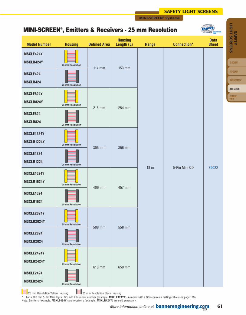
61More information online at bannerengineering.com
MINI-SCREEN® Systems
EZ-SCREEN®
PICO-GUARD™
MICRO-SCREEN®
MINI-SCREEN®
SAFETY
LIGH
T SCR
EENS
EZ-SCREEN ®TYPE 2
SAFETY LIGHT SCREENS
MINI-SCREEN®, Emitters & Receivers - 25 mm Resolution
Model Number Housing Defined AreaHousing
Length (L) Range Connection*Data Sheet
MSXLE424Y
25 mm Resolution114 mm 153 mm
18 m 5-Pin Mini QD 39022
MSXLR424Y
MSXLE424
25 mm Resolution
MSXLR424
MSXLE824Y
25 mm Resolution215 mm 254 mm
MSXLR824Y
MSXLE824
25 mm Resolution
MSXLR824
MSXLE1224Y
25 mm Resolution305 mm 356 mm
MSXLR1224Y
MSXLE1224
25 mm Resolution
MSXLR1224
MSXLE1624Y
25 mm Resolution406 mm 457 mm
MSXLR1624Y
MSXLE1624
25 mm Resolution
MSXLR1624
MSXLE2024Y
25 mm Resolution508 mm 558 mm
MSXLR2024Y
MSXLE2024
25 mm Resolution
MSXLR2024
MSXLE2424Y
25 mm Resolution610 mm 659 mm
MSXLR2424Y
MSXLE2424
25 mm Resolution
MSXLR2424
25 mm Resolution Yellow Housing 25 mm Resolution Black Housing* For a 305 mm 5-Pin Mini Pigtail QD, add P to model number (example, MSXLE424YP). A model with a QD requires a mating cable (see page 179).Note: Emitters (example, MSXLE424Y) and receivers (example, MSXLR424Y) are sold separately.
DownloadPDF

62 More information online at bannerengineering.com
EZ-SCREEN®
PICO-GUARD™
MICRO-SCREEN®
MINI-SCREEN®
SAFE
TYLI
GH
T SC
REE
NS
EZ-SCREEN® TYPE 2
MINI-SCREEN® Systems
SAFETY LIGHT SCREENS
MINI-SCREEN®, Emitters & Receivers - 25 mm Resolution
Model Number Housing Defined AreaHousing
Length (L) Range Connection*Data Sheet
MSXLE2824Y
25 mm Resolution711 mm 761 mm
18 m 5-Pin Mini QD 39022
MSXLR2824Y
MSXLE2824
25 mm Resolution
MSXLR2824
MSXLE3224Y
25 mm Resolution813 mm 862 mm
MSXLR3224Y
MSXLE3224
25 mm Resolution
MSXLR3224
MSXLE3624Y
25 mm Resolution914 mm 963 mm
MSXLR3624Y
MSXLE3624
25 mm Resolution
MSXLR3624
MSXLE4024Y
25 mm Resolution1016 mm 1064 mm
MSXLR4024Y
MSXLE4024
25 mm Resolution
MSXLR4024
MSXLE4424Y
25 mm Resolution1118 mm 1166 mm
MSXLR4424Y
MSXLE4424
25 mm Resolution
MSXLR4424
MSXLE4824Y
25 mm Resolution1219 mm 1267 mm
MSXLR4824Y
MSXLE4824
25 mm Resolution
MSXLR4824
25 mm Resolution Yellow Housing 25 mm Resolution Black Housing* For a 305 mm 5-Pin Mini Pigtail QD, add P to model number (example, MSXLE2824YP). A model with a QD requires a mating cable (see page 179).Note: Emitters (example, MSXLE2824Y) and receivers (example, MSXLR2824Y) are sold separately.
DownloadPDF
(cont’d)

63More information online at bannerengineering.com
MINI-SCREEN® Systems
EZ-SCREEN®
PICO-GUARD™
MICRO-SCREEN®
MINI-SCREEN®
SAFETY
LIGH
T SCR
EENS
EZ-SCREEN ®TYPE 2
SAFETY LIGHT SCREENS
MINI-SCREEN® Heavy-Duty Emitters & Receivers - 38 mm Resolution
Model Number Resolution Defined AreaHousing
Length (L) Range Connection*Data Sheet
MSXLHDE2412Y
38 mm Resolution
610 mm 625 mm
18 m 5-Pin Mini QD 69018
MSXLHDR2412Y
MSXLHDE3212Y813 mm 826 mm
MSXLHDR3212Y
MSXLHDE4012Y1016 mm 1029 mm
MSXLHDR4012Y
MSXLHDE4812Y1219 mm 1229 mm
MSXLHDR4812Y
MSXLHDE5612Y1422 mm 1433 mm
MSXLHDR5612Y
MSXLHDE6412Y1626 mm 1633 mm
MSXLHDR6412Y
MSXLHDE7212Y1829 mm 1836 mm
MSXLHDR7212Y
38 mm Resolution * For a 305 mm 5-Pin Mini Pigtail QD, add P to model number (example, MSXLHDE2412YP). A model with a QD requires a mating cable (see page 179).Note: Emitters (example, MSXLHDE2412Y) and receivers (example, MSXLHDR2412Y) are sold separately.
Robust, impact-resistant housing
38 mm resolution with 18 m range
Seven heights from 610 to 1829 mm
High immunity to ambient light interference
Status indicators
Swivel bracket for easy alignment
5-pin Mini QD connection standard
QDS-... 5-pin Mini QD with “twisted pair” (see page 179)
NEMA 4, 13; IEC IP65 housing
MINI-SCREEN® Heavy-Duty Emitters & Receivers
MINI-SCREEN Heavy-Duty Emitters & Receivers
DetailedDimensions
55.0 mm
L
52.0 mm
Full View
Yellow Painted Aluminum
DownloadPDF

64 More information online at bannerengineering.com
EZ-SCREEN®
PICO-GUARD™
MICRO-SCREEN®
MINI-SCREEN®
SAFE
TYLI
GH
T SC
REE
NS
EZ-SCREEN® TYPE 2
MINI-SCREEN® Systems
SAFETY LIGHT SCREENS
MINI-SCREEN® Series, Metal Box Controllers
ModelsSupply
VoltageOutput Type
SafetyOutputs*
OutputRating
Aux. Outputs**
Floating Blanking
Fixed Blanking
Data Sheet
MSCT-1
24V dc Trip
2 NO
4 amps —2-beam No
39022
MSCT-1T3 6 amps 1 NC 59664 & 39022
MSCT-2 4 amps —1- or 2-beam Yes
47295
MSCT-2T3 6 amps 1 NC 59664 & 47295
MSCA-1
115V ac
Trip4 amps —
2-beam No
39022
MSCA-1T3 6 amps 1 NC 59664 & 39022
MSCA-1L2
Latch
4 amps — 55702
MSCA-1L3 6 amps 1 NC 59664 & 55702
MSCA-1L3E* 6 amps 1 NC 46904 & 55702
MSCA-1S2E* Trip/LatchSelectable
4 amps — 39022
MSCA-1S3E* 6 amps 1 NC 39022
MSCB-1
230V acTrip
4 amps — 39022
MSCB-1T3 6 amps 1 NC 59664 & 39022
MSCB-1L2 Latch 4 amps — 55702
MSCD-2115/230V ac Trip
4 amps —1- or 2-beam Yes
47295
MSCD-2T3 6 amps 1 NC 59644 & 47295
Welded steel box with polyester powder paint finish
115/230V ac or 24V dc supply voltage
Floating blanking and selectable auto power-up
Optional fixed blanking, muting and External Device Monitoring (EDM)
Latch or trip output
NEMA 13, IEC IP64 housing
MINI-SCREEN® Metal Box Controllers
MINI-SCREEN Metal Box Controller(MSCA-1 shown)
MINI-SCREEN Metal Box Controller with Muting(MSCC-2T2M shown)
244.0 mm
210.0 mm
295.0 mm
260.0 mm
85.0 mm
84.0 mm
NC = Normally Closed Relay, NO = Normally Open Relay* The suffix “E” adds external device monitoring input** All models contain one Reed Relay (see specifications page 73)
DownloadPDF

65More information online at bannerengineering.com
MINI-SCREEN® Systems
EZ-SCREEN®
PICO-GUARD™
MICRO-SCREEN®
MINI-SCREEN®
SAFETY
LIGH
T SCR
EENS
EZ-SCREEN ®TYPE 2
SAFETY LIGHT SCREENS
Polycarbonate housing with removable terminal blocks and clear cover
24V dc supply voltage
Floating blanking and selectable auto power-up
Latch or trip output
Dual models for two emitter/receiver pairs
NEMA 1; IP20 housing
MINI-SCREEN® DIN Module Controllers
MINI-SCREEN Dual DIN Module Controller(MDSDINT-1T2 shown)
DetailedDimensions
83.8 mm
149.0 mm
110.0 mm
MINI-SCREEN DIN Module Controller(MSDINT-1 shown)
100.0 mm
75.0 mm
110.0 mm
DownloadPDF
MINI-SCREEN Series, DIN Module Controllers
ModelsSupply Voltage
Output Type
SafetyOutputs*
OutputRating
Floating Blanking
Fixed Blanking
E-StopInput
Light ScreenPairs/Controller
DataSheet
MSDINT-1
24V dc
Trip
2 NO 4 amps
2-beam
No
No
1 Pair
44895
MSDINT-1L2 Latch
MDSDINT-1T2 Trip1- or
2-beam Yes
2 Pairs
47297 & 60159
MDSDINT-1L2 Latch
NC = Normally Closed Relay, NO = Normally Open Relay* In addition to safety outputs, all models contain either one or two non-safety Reed Relay auxiliary outputs (see specifications pages 76-77).
MINI-SCREEN® Series, Metal Box Controllers with Muting
ModelsSupply
VoltageOutput Type
SafetyOutputs
OutputRating
Aux. Outputs**
Floating Blanking
Fixed Blanking
Data Sheet
MSCC-2T2M 115/230V ac or
24V dcTrip
2 NO
4 amps —
1- or 2-beam Yes
64723MSCC-2T3M 6 amps 1 NC
MSCC-2L2M 115/230V ac or
24V dcLatch
4 amps —61409
MSCC-2L3M 6 amps 1 NC
NC = Normally Closed Relay, NO = Normally Open Relay* All models contain two Reed Relays (see specifications pages 74-75)Note: External Device Monitoring (EDM) standard on all controllers with muting.
DownloadPDF

66 More information online at bannerengineering.com
EZ-SCREEN®
PICO-GUARD™
MICRO-SCREEN®
MINI-SCREEN®
SAFE
TYLI
GH
T SC
REE
NS
EZ-SCREEN® TYPE 2
MINI-SCREEN® Systems
SAFETY LIGHT SCREENS
MINI-SCREEN® Interfacing Products
Models DescriptionProduct
InformationDataSheet
Mut
ing
Mod
ules MM-TA-12B
• The Muting Module temporarily inhibits a safety light screen so materials can safely pass through the screen without stopping the machinery.
• The module uses redundant microcontroller-based logic.
Page 123
63517
MMD-TA-12B
116390
MMD-TA-11B
Cont
acto
rs
MechanicallyLinked Contactors
• Pairs of contactors create safety stop circuits with two normally open contacts in series.
• MINI-SCREEN can monitor the circuit because of the contacts’ force-guided mechanically linked design.
• Contactors add 10 or 16 amp current carrying capability to any safety system.
• Auxiliary contacts add 3 or 4 normally open contacts.
• Suppressors extend the life of an actuating device that uses a contactor.
• Modular design simplifies assembly and installation.
Page 186 111881
11-BG00-31-A12060
11-BG00-31-D-024
11-BF1601-12060
11-BF16C01-024
Aux. Contacts
11-BGX10-40
11-G484-30
Suppressors
11-BGX77-048
11-BGX77-240
11-G318-48
11-G477-240
DownloadPDF

67More information online at bannerengineering.com
MINI-SCREEN® Systems
EZ-SCREEN®
PICO-GUARD™
MICRO-SCREEN®
MINI-SCREEN®
SAFETY
LIGH
T SCR
EENS
EZ-SCREEN ®TYPE 2
SAFETY LIGHT SCREENS
MINI-SCREEN® Metal Box Controller Kits - Floating Blanking
Kit Model Key
Model StyleMS = MINI-SCREEN
Model Style
2 4K
Kit SupplyVoltage
OutputType
QD Cables Sensor CableTermination
Max. Emitter/Receiver SeparationBlank = 9 mXL = 18 mXLHD = Heavy-Duty 18 m
KitK = Kit
Quick-Disconnect CablesC1 = 2 x 5 mC2 = 2 x 8 mC3 = 1 x 5 m plus 1 x 8 m
Defi nedArea
Sensor FinishBlank = Black anodizedY = Yellow polyester paint
Supply VoltageA = 115V acB = 230V acT = 24V dc
OptionsE = With External Device Monitoring (EDM)Blank = Without
A
Options
2 4
BeamsPer Foot
3 C 2
Finish
Beams per Foot24 = Standard & Long-Range Series12 = Heavy-Duty Series
Output TypeBlank = TripL = LatchS = Trip/Latch Selectable
Output ConfigurationBlank= 2 NO Safety Outputs3 = 2 NO Safety Outputs &
1 NC Aux.
Sensor Cable TerminationBlank = Integral QD connectorP = Pigtail QD
Output Confi guration
M S
MSKT24243C2 •
610 mm
19 mm
24
9 m
24V dc
Trip
2 NOSafety
Outputs&
1 NC Aux.
8 m, 2 each
MSKT24243C2Y •MSXLKT24243C2 • 25 mm 18 mMSXLKT24243C2Y •MSXLHDKT24123C2Y • 38 mm 12 18 m
MSKA24243C2 • 19 mm
24
9 m
115V ac
MSKA24243C2Y •MSXLKA24243C2 • 25 mm 18 mMSXLKA24243C2Y •MSXLHDKA24123C2Y • 38 mm 12 18 m
MSKB24243C2 • 19 mm
24
9 m
230V ac
MSKB24243C2Y •MSXLKB24243C2 • 25 mm 18 mMSXLKB24243C2Y •MSXLHDKB24123C2Y • 38 mm 12 18 m
Kit Model Number
SensorHousing
Def
ined
Are
a
Res
olut
ion
Beam
s Pe
r Fo
ot
Ran
ge
Supp
ly
Volt
age
Out
put T
ype
Num
ber
of
Out
puts
QD
Cab
ling
Yellow Black
Heavy- Duty
Yellow
Emitter/Receiver Separation
X L PY
You can purchase a kit that contains an emitter and receiver of equal length and range; standard mounting brackets; and a pair of quick-disconnect cables. Detailed information about individual kit components is as follows.
• Metal Box Controllers – Floating Blanking . . . . . . . . . . . . . . . . . .Page 64• Emitter and Receivers . . . . . . . . . . . . . . . . . . . . . . . . . . . . . . . . . . . 59-63• Cables . . . . . . . . . . . . . . . . . . . . . . . . . . . . . . . . . . . . . . . . . . . . . . . . . 179• Brackets . . . . . . . . . . . . . . . . . . . . . . . . . . . . . . . . . . . . . . . . . . . . . . . . 190
A partial listing of kits is listed below; see Kit Model Key to order other variations.
Defined Area4 = 114 mm8 = 215 mm12 = 305 mm16 = 406 mm20 = 508 mm24 = 610 mm28 = 711 mm32 = 813 mm36 = 914 mm40 = 1016 mm44 = 1118 mm48 = 1219 mm
NC = Normally Closed Relay, NO = Normally Open Relay
NOTE: Not all combinations are possible. Contact Banner Engineering Corp. for additional information and/or verification of valid kit model number.

68 More information online at bannerengineering.com
EZ-SCREEN®
PICO-GUARD™
MICRO-SCREEN®
MINI-SCREEN®
SAFE
TYLI
GH
T SC
REE
NS
EZ-SCREEN® TYPE 2
MINI-SCREEN® Systems
SAFETY LIGHT SCREENS
MINI-SCREEN® Metal Box Kits - Floating & Fixed Blanking
MSK2T24243C2 •
610 mm
19 mm
24
9 m
24V dc
Trip
2 NOSafety
Outputs&
1 NC Aux.
8 m, 2 each
MSK2T24243C2Y •MSXLK2T24243C2 • 25 mm 18 mMSXLK2T24243C2Y •MSXLHDK2T24123C2Y • 38 mm 12 18 m
MSK2D24243C2 • 19 mm
24
9 m
115/230V ac
MSK2D24243C2Y •MSXLK2D24243C2 • 25 mm 18 mMSXLK2D24243C2Y •MSXLHDK2D24123C2Y • 38 mm 12 18 m
Kit Model Number
SensorHousing
Def
ined
Are
a
Res
olut
ion
Beam
s Pe
r Fo
ot
Ran
ge
Supp
ly
Volt
age
Out
put T
ype
Num
ber
of
Out
puts
QD
Cab
ling
Yellow Black
Heavy- Duty
Yellow
Kit Model Key
Model StyleMS = MINI-SCREEN
Model Style
2 4K
Kit Blanking QD Cables Sensor CableTermination
Max. Emitter/Receiver SeparationBlank = 9 mXL = 18 mXLHD = Heavy-Duty 18 m
KitK = Kit
Quick-Disconnect CablesC1 = 2 x 5 mC2 = 2 x 8 mC3 = 1 x 5 m plus 1 x 8 m
Defi nedArea
Sensor FinishBlank = Black anodizedY = Yellow polyester paint
Supply VoltageD = 115/230V acT = 24V dc
Blanking2 = Floating & Fixed Blanking
2 D
SupplyVoltage
2 4
BeamsPer Foot
3 C 2
Finish
Beams per Foot24 = Standard & Long-Range Series12 = Heavy-Duty Series
Output ConfigurationBlank= 2 NO Safety Outputs3 = 2 NO Safety Outputs &
1 NC Aux.
Sensor Cable TerminationBlank = Integral QD connectorP = Pigtail QD
Output Confi guration
M S
Emitter/Receiver Separation
X L PY
You can purchase a kit that contains an emitter and receiver of equal length and range; standard mounting brackets; and a pair of quick-disconnect cables. Detailed information about individual kit components is as follows.
• Metal Box Controllers – Floating & Fixed Blanking . . . . . . . . . . .Page 64• Emitter and Receivers . . . . . . . . . . . . . . . . . . . . . . . . . . . . . . . . . . . 59-63• Cables . . . . . . . . . . . . . . . . . . . . . . . . . . . . . . . . . . . . . . . . . . . . . . . . . 179• Brackets . . . . . . . . . . . . . . . . . . . . . . . . . . . . . . . . . . . . . . . . . . . . . . . . 190
A partial listing of kits is listed below; see Kit Model Key to order other variations.
Defined Area4 = 114 mm8 = 215 mm12 = 305 mm16 = 406 mm20 = 508 mm24 = 610 mm28 = 711 mm32 = 813 mm36 = 914 mm40 = 1016 mm44 = 1118 mm48 = 1219 mm
NC = Normally Closed Relay, NO = Normally Open Relay
NOTE: Not all combinations are possible. Contact Banner Engineering Corp. for additional information and/or verification of valid kit model number.

69More information online at bannerengineering.com
MINI-SCREEN® Systems
EZ-SCREEN®
PICO-GUARD™
MICRO-SCREEN®
MINI-SCREEN®
SAFETY
LIGH
T SCR
EENS
EZ-SCREEN ®TYPE 2
SAFETY LIGHT SCREENS
MINI-SCREEN® Metal Box with Muting Kits - Floating & Fixed Blanking
MSK2CM24243C2 •
610 mm
19 mm
24
9 m115/230V ac
or24V dc
Trip
2 NOSafety
Outputs&
1 NC Aux.
8 m, 2 each
MSK2CM24243C2Y •MSXLK2CM24243C2 • 25 mm 18 mMSXLK2CM24243C2Y •MSXLHDK2CM24123C2Y • 38 mm 12 18 m
Kit Model Number
SensorHousing
Def
ined
Are
a
Res
olut
ion
Beam
s Pe
r Fo
ot
Ran
ge
Supp
ly
Volt
age
Out
put T
ype
Num
ber
of
Out
puts
QD
Cab
ling
Yellow Black
Heavy- Duty
Yellow
Kit Model Key
Model StyleMS = MINI-SCREEN
Model Style
2 4K
Kit Blanking QD Cables Sensor CableTermination
Max. Emitter/Receiver SeparationBlank = 9 mXL = 18 mXLHD = Heavy-Duty 18 m
KitK = Kit
Quick-Disconnect CablesC1 = 2 x 5 mC2 = 2 x 8 mC3 = 1 x 5 m plus 1 x 8 m
Defi nedArea
Sensor FinishBlank = Black anodizedY = Yellow polyester paint
Supply VoltageC = 115/230V ac or 24V dc
2 C
SupplyVoltage
BeamsPer Foot
C 2
Finish
Beams per Foot24 = Standard & Long-Range Series12 = Heavy-Duty Series
Number of OutputsBlank= 2 NO Safety Outputs3 = 2 NO Safety Outputs &
1 NC Aux.
Sensor Cable TerminationBlank = Integral QD connectorP = Pigtail QD
No. ofOutputs
M S
Emitter/Receiver Separation
X L PYM
Muting OutputType
2 4
Output TypeBlank = TripL = Latch
Muting FunctionM = Muting
Blanking2 = Floating & Fixed Blanking
You can purchase a kit that contains an emitter and receiver of equal length and range; standard mounting brackets; and a pair of quick-disconnect cables. Detailed information about individual kit components is as follows.
• Metal Box Controllers with Muting – Floating & Floating Blanking . . . . . . . .Page 65• Emitter and Receivers . . . . . . . . . . . . . . . . . . . . . . . . . . . . . . . . . . . . . . . . . . . . 59-63• Cables . . . . . . . . . . . . . . . . . . . . . . . . . . . . . . . . . . . . . . . . . . . . . . . . . . . . . . . . . . 179 • Brackets . . . . . . . . . . . . . . . . . . . . . . . . . . . . . . . . . . . . . . . . . . . . . . . . . . . . . . . . . 190
A partial listing of kits is listed below; see Kit Model Key to order other variations.
NOTE: Not all combinations are possible. Contact Banner Engineering Corp. for additional information and/or verification of valid kit model number.
NC = Normally Closed Relay, NO = Normally Open Relay
Defined Area4 = 114 mm8 = 215 mm12 = 305 mm16 = 406 mm20 = 508 mm24 = 610 mm28 = 711 mm32 = 813 mm36 = 914 mm40 = 1016 mm44 = 1118 mm48 = 1219 mm

70 More information online at bannerengineering.com
EZ-SCREEN®
PICO-GUARD™
MICRO-SCREEN®
MINI-SCREEN®
SAFE
TYLI
GH
T SC
REE
NS
EZ-SCREEN® TYPE 2
MINI-SCREEN® Systems
SAFETY LIGHT SCREENS
MINI-SCREEN® DIN Module Controller Kits - Floating Blanking
MSDKT2424C2 •
610 mm
19 mm
24
9 m
24V dc Trip2 NO
SafetyOutputs
8 m, 2 each
MSDKT2424C2Y •MSXLDKT2424C2 • 25 mm 18 mMSXLDKT2424C2Y •MSXLHDKT2412C2Y • 38 mm 12 18 m
Kit Model Number
SensorHousing
Def
ined
Are
a
Res
olut
ion
Beam
s Pe
r Fo
ot
Ran
ge
Supp
ly
Volt
age
Out
put T
ype
Num
ber
of
Out
puts
QD
Cab
ling
Yellow Black
Heavy- Duty
Yellow
Kit Model Key
Model Style*MS = MINI-SCREEN
Model Style*
2 4
Kit QD Cables Sensor CableTermination
Max. Emitter/Receiver SeparationBlank = 9 mXL = 18 mXLHD = Heavy-Duty 18 m
KitDK = DIN-style
controller Kit
Quick-Disconnect CablesC1 = 2 x 5 mC2 = 2 x 8 mC3 = 1 x 5 m plus 1 x 8 m
Defi nedArea
Sensor FinishBlank = Black anodizedY = Yellow polyester paint
Supply VoltageT = 24V dc
T
SupplyVoltage
2 4
BeamsPer Foot
C 2
Finish
Beams per Foot24 = Standard & Long-Range Series12 = Heavy-Duty Series
Sensor Cable TerminationBlank = Integral QD connectorP = Pigtail QD
OutputType
M S
Emitter/Receiver Separation
X L PY
Output TypeBlank = TripL = Latch
D K
You can purchase a kit that contains an emitter and receiver of equal length and range; standard mounting brackets; and a pair of quick-disconnect cables. Detailed information about individual kit components is as follows.
• DIN Module Controllers – Floating Blanking . . . . . . . . . . . . . . . . .Page 65• Emitter and Receivers . . . . . . . . . . . . . . . . . . . . . . . . . . . . . . . . . . . 59-63• Cables . . . . . . . . . . . . . . . . . . . . . . . . . . . . . . . . . . . . . . . . . . . . . . . . . 179• Brackets . . . . . . . . . . . . . . . . . . . . . . . . . . . . . . . . . . . . . . . . . . . . . . . . 190
A partial listing of kits is listed below; see Kit Model Key to order other variations.
* Kits are not available for Dual DIN Modules. A controller, two emitter/receiver pairs and the appropriate cables are sold separately (see page 179).NOTE: Not all combinations are possible. Contact Banner Engineering Corp. for additional information and/or verification of valid kit model number.
NC = Normally Closed Relay, NO = Normally Open Relay
Defined Area4 = 114 mm8 = 215 mm12 = 305 mm16 = 406 mm20 = 508 mm24 = 610 mm28 = 711 mm32 = 813 mm36 = 914 mm40 = 1016 mm44 = 1118 mm48 = 1219 mm

71More information online at bannerengineering.com
MINI-SCREEN® Systems
EZ-SCREEN®
PICO-GUARD™
MICRO-SCREEN®
MINI-SCREEN®
SAFETY
LIGH
T SCR
EENS
EZ-SCREEN ®TYPE 2
SAFETY LIGHT SCREENS
MINI-SCREEN® Emitter & Receiver SpecificationsEmitter/Receiver Separation 19 mm Resolution Emitters and Receivers: 150 mm to 9 m
25.4 mm Resolution Emitters and Receivers: 150 mm to 18 m
Minimum Object Sensitivity 19 mm Resolution:19.1 mm floating blanking OFF31.8 mm 1-beam floating blanking ON44.5 mm 2-beam floating blanking ON
25.4 mm Resolution:25.4 mm floating blanking OFF38.1 mm 1-beam floating blanking ON50.8 mm 2-beam floating blanking ON
Response Time Less than 48 milliseconds using emitter/receiver with 114 to 406 mm defined areaLess than 60 milliseconds using emitter/receiver with 508 to 813 mm defined areaLess than 72 milliseconds using emitter/receiver with 914 to 1219 mm defined area
Self-Checking Interval 20 milliseconds
Ambient Light Immunity >10,000 lux at 5° angle of incidence
Strobe Light Immunity Totally immune to one Federal Signal Corp. “Fireball” model FB2PST strobe.
Emitter Elements Infrared LEDs; 880 nm peak emission
Status Indicators Emitter: Green LED for power ONReceiver: Red, yellow and green status indicators with the same functions as those on the left side of
the control box (see individual Control Box Specifications, pages 73-77). Yellow also indicates alignment. Indicators are visible on three sides of receiver or emitter base.
Emitter and Receiver Enclosures
Materials: Aluminum extrusion with black anodized or yellow polyester painted finish; acrylic lens coverMounting hardware suppliedRating: NEMA 4, 13; IEC IP65
Mounting Hardware Emitter and receiver are each supplied with a pair of mounting brackets. Mounting brackets are 11-gauge cold-rolled black zinc chromate finished steel. A set of four vibration dampening mounts is also supplied.
Cables Emitters and Receivers with Pigtail (MSE/MSRxxxxYP) Quick Disconnect:Pigtail QD connectors have a 305 mm long cable, terminated with a 5-pin Mini-style quick-disconnect fitting. Mating interconnect cables are ordered separately (unless a MINI-SCREEN kit is ordered, see Models and Accessories, page 179), and are available in lengths of 4.5 m, 7.6 m, 15 m, 30 m and 45 m.
NOTE: Contact factory when cable length exceeding 53 m is required. Use only Banner cables, which incorporate a shielded “twisted pair” for noise immunity on RS485 data communications lines. Use of other cables may result in “nuisance” trips or lockouts.
Optical Performance This system meets ± 2.5° requirements of IEC 61496-2, section 5.2.9 (Type 4)
Operating Conditions Temperature: 0° to +50° C Relative humidity: 95% maximum (non-condensing)
Certifications For a list of certifications see page 236.

72 More information online at bannerengineering.com
EZ-SCREEN®
PICO-GUARD™
MICRO-SCREEN®
MINI-SCREEN®
SAFE
TYLI
GH
T SC
REE
NS
EZ-SCREEN® TYPE 2
MINI-SCREEN® Systems
SAFETY LIGHT SCREENS
MINI-SCREEN® Heavy-Duty Emitter & Receiver SpecificationsEmitter/Receiver Separation 150 mm to 18 m
Minimum Object Sensitivity 38 mm floating blanking OFF62 mm 1-beam floating blanking ON89 mm 2-beam floating blanking ON
Response Time Less than 48 milliseconds for 610 mm and 813 mm emitter/receiverLess than 60 milliseconds for 1016 mm to 1626 mm emitter/receiverLess than 72 milliseconds for 1829 mm emitter/receiver
Self-Checking Interval 20 milliseconds
Ambient Light Immunity >10,000 lux at 5° angle of incidence
Strobe Light Immunity Totally immune to one Federal Signal Corp. “Fireball” model FB2PST strobe.
Emitter Elements Infrared LEDs; 880 nm peak emission
Status Indicators Emitter: Green LED for power ONReceiver: Red, yellow and green status indicators with the same functions as those on the left side of
the control box (see individual Control Box Specifications, pages 73-77). Yellow also indicates alignment. Indicators are visible on three sides of receiver or emitter base.
Emitter and Receiver Enclosures
Materials: Aluminum extrusion with yellow polyester painted finish; acrylic lens cover. Mounting hardware supplied.Rating: NEMA 4, 13; IEC IP65
Mounting Hardware Emitter and receiver are each supplied with a pair of mounting brackets. Mounting brackets are 8-gauge cold-rolled black zinc chromate finished steel.
Cables Emitters and Receivers with Pigtail (MSXLHDE/MSXLHDRxxxxYP) Quick Disconnect:Pigtail QD connectors have a 305 mm long cable, terminated with a 5-pin Mini-style quick-disconnect fitting. Mating interconnect cables are ordered separately (unless a MINI-SCREEN kit is ordered, see Models and Accessories, page 179), and are available in lengths of 4.5 m, 7.6 m, 15 m, 30 m and 45 m.
NOTE: Contact factory when cable length exceeding 53 m is required. Use only Banner cables, which incorporate a shielded “twisted pair” for noise immunity on RS485 data communications lines. Use of other cables may result in “nuisance” trips or lockouts.
Optical Performance This system meets ± 2.5° requirements of IEC 61496-2, section 5.2.9 (Type 4)
Operating Conditions Temperature: 0° to +50° C Relative humidity: 95% maximum (non-condensing)
Certifications For a list of certifications see page 236.
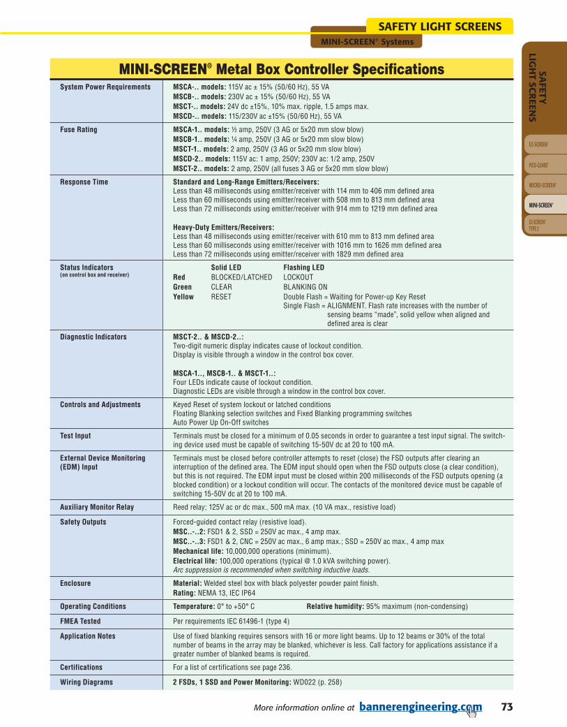
73More information online at bannerengineering.com
MINI-SCREEN® Systems
EZ-SCREEN®
PICO-GUARD™
MICRO-SCREEN®
MINI-SCREEN®
SAFETY
LIGH
T SCR
EENS
EZ-SCREEN ®TYPE 2
SAFETY LIGHT SCREENS
MINI-SCREEN® Metal Box Controller SpecificationsSystem Power Requirements MSCA-.. models: 115V ac ± 15% (50/60 Hz), 55 VA
MSCB-.. models: 230V ac ± 15% (50/60 Hz), 55 VAMSCT-.. models: 24V dc ±15%, 10% max. ripple, 1.5 amps max.MSCD-.. models: 115/230V ac ±15% (50/60 Hz), 55 VA
Fuse Rating MSCA-1.. models: ½ amp, 250V (3 AG or 5x20 mm slow blow)MSCB-1.. models: ¼ amp, 250V (3 AG or 5x20 mm slow blow)MSCT-1.. models: 2 amp, 250V (3 AG or 5x20 mm slow blow)MSCD-2.. models: 115V ac: 1 amp, 250V; 230V ac: 1/2 amp, 250VMSCT-2.. models: 2 amp, 250V (all fuses 3 AG or 5x20 mm slow blow)
Response Time Standard and Long-Range Emitters/Receivers:Less than 48 milliseconds using emitter/receiver with 114 mm to 406 mm defined areaLess than 60 milliseconds using emitter/receiver with 508 mm to 813 mm defined areaLess than 72 milliseconds using emitter/receiver with 914 mm to 1219 mm defined area
Heavy-Duty Emitters/Receivers:Less than 48 milliseconds using emitter/receiver with 610 mm to 813 mm defined areaLess than 60 milliseconds using emitter/receiver with 1016 mm to 1626 mm defined areaLess than 72 milliseconds using emitter/receiver with 1829 mm defined area
Status Indicators(on control box and receiver)
Solid LED Flashing LEDRed BLOCKED/LATCHED LOCKOUTGreen CLEAR BLANKING ONYellow RESET Double Flash = Waiting for Power-up Key Reset Single Flash = ALIGNMENT. Flash rate increases with the number of
sensing beams “made”, solid yellow when aligned and defined area is clear
Diagnostic Indicators MSCT-2.. & MSCD-2..:Two-digit numeric display indicates cause of lockout condition.Display is visible through a window in the control box cover.
MSCA-1.., MSCB-1.. & MSCT-1..:Four LEDs indicate cause of lockout condition.Diagnostic LEDs are visible through a window in the control box cover.
Controls and Adjustments Keyed Reset of system lockout or latched conditionsFloating Blanking selection switches and Fixed Blanking programming switchesAuto Power Up On-Off switches
Test Input Terminals must be closed for a minimum of 0.05 seconds in order to guar an tee a test input signal. The switch-ing device used must be capable of switching 15-50V dc at 20 to 100 mA.
External Device Monitoring (EDM) Input
Terminals must be closed before controller attempts to reset (close) the FSD outputs after clearing an interruption of the defined area. The EDM input should open when the FSD outputs close (a clear condition), but this is not required. The EDM input must be closed within 200 milliseconds of the FSD outputs opening (a blocked condition) or a lockout condition will occur. The contacts of the monitored device must be capable of switching 15-50V dc at 20 to 100 mA.
Auxiliary Monitor Relay Reed relay; 125V ac or dc max., 500 mA max. (10 VA max., resistive load)
Safety Outputs Forced-guided contact relay (resistive load). MSC..-..2: FSD1 & 2, SSD = 250V ac max., 4 amp max.MSC..-..3: FSD1 & 2, CNC = 250V ac max., 6 amp max.; SSD = 250V ac max., 4 amp maxMechanical life: 10,000,000 operations (minimum). Electrical life: 100,000 operations (typical @ 1.0 kVA switching power). Arc suppression is recommended when switching inductive loads.
Enclosure Material: Welded steel box with black polyester powder paint finish.Rating: NEMA 13, IEC IP64
Operating Conditions Temperature: 0° to +50° C Relative humidity: 95% maximum (non-condensing)
FMEA Tested Per requirements IEC 61496-1 (type 4)
Application Notes Use of fixed blanking requires sensors with 16 or more light beams. Up to 12 beams or 30% of the total number of beams in the array may be blanked, whichever is less. Call factory for applications assistance if a greater number of blanked beams is required.
Certifications For a list of certifications see page 236.
Wiring Diagrams 2 FSDs, 1 SSD and Power Monitoring: WD022 (p. 258)

74 More information online at bannerengineering.com
EZ-SCREEN®
PICO-GUARD™
MICRO-SCREEN®
MINI-SCREEN®
SAFE
TYLI
GH
T SC
REE
NS
EZ-SCREEN® TYPE 2
MINI-SCREEN® Systems
SAFETY LIGHT SCREENS
MINI-SCREEN® Metal Box Controller with Muting SpecificationsSystem Power Requirements 115V ac (50/60Hz) ± 15% @ 500 mA (50 VA),
230V ac (50/60Hz) ± 15% @ 250 mA (50 VA), or24V dc ±15%, 10% max. ripple, @ 2.5 A (60 W)
Fuse Rating 115V ac: 1.0 A @ 250V ac (supplied) 230V ac: 500 mA @ 250V ac+24V dc: Internal resettable
Response Time Standard and Long-Range Emitters/Receivers:Less than 58 milliseconds using emitter/receiver with 114 mm to 406 mm defined areaLess than 70 milliseconds using emitter/receiver with 508 mm to 813 mm defined areaLess than 82 milliseconds using emitter/receiver with 914 mm to 1219 mm defined area
Heavy-Duty Emitters/Receivers:Less than 58 milliseconds using emitter/receiver with 610 mm to 813 mm defined areaLess than 70 milliseconds using emitter/receiver with 1016 mm to 1626 mm defined areaLess than 82 milliseconds using emitter/receiver with 1829 mm defined area
Status Indicators(on control box and receiver)
Standard models:Light Screen Indicators (left column of LEDs): Solid LED Flashing LEDRed BLOCKED/LATCHED LOCKOUTGreen CLEAR BLANKING ONYellow RESET Double Flash = Waiting for Light Screen Key Reset at Power-up Single Flash = ALIGNMENT. Flash rate increases with the number of
sensing beams “made”, solid yellow when aligned and defined area clear
System Indicators (right column of LEDs): Solid LED Flashing LEDRed OVERRIDE LOCKOUTGreen OUTPUT ON (Not Applicable) (FSD1 & FSD2 closed)Yellow RESET Double Flash = Waiting for System Key Reset at Power-up (System) Single Flash = Waiting for System Key Reset at latched condition (manual
reset of system after blockage has been removed)
Diagnostic Indicators Light Screen Diagnostic Display (left window) is a two-digit numeric display that indicates the causeof lockout conditions.System Diagnostic Display (right window) is a two-digit numeric display that indicates the cause oflockout conditions and the amount of time, in seconds, remaining for the backdoor timer.
Controls and Adjustments • Light Screen Key Reset after power-up and light screen lockouts• Selection switches to enable floating blanking• Program switches to enable fixed blanking• Light Screen and System Auto Power-up selection switches• System Key Reset after power-up, system lockouts, and latched conditions• Selection switches for Monitored or Non-Monitored Muting Indicator• Selection switches for One-Way or Two-Way (directional/non-directional) Muting• Selection switches for One-Channel, Two-Channel Monitoring or No Monitoring (EDM)• Selection switches for Backdoor Timer settings and Mute-on-Power-Up
Light Screen and System Reset Inputs
Terminals must be closed for a minimum of 0.05 seconds in order to guarantee a reset. Theswitching device must be capable of switching 15-50V dc at 20-100 mA.
External Device Monitoring(EDM) Input(s)
Two pairs of terminals are provided to monitor the state of external devices that are being controlledby the FSD outputs. The device must be capable of switching 15-50V dc at 20-100 mA.
Mute Enable Input Terminals must be closed in order to start a mute; opening this input after mute has begun has noeffect. The switching device must be capable of switching 15-50V dc at 20-100 mA.
Override Inputs The two-channel inputs must be closed within 3 seconds of each other (simultaneity requirement)and held closed during the 10-second Override. To initiate a subsequent Override, open bothchannels, wait 3 seconds, and then re-close both channels (within 3 seconds). The switching devicesmust be capable of switching 15-50V dc at 20-100 mA.
Muting Device Input The muting devices work in pairs (M1 and M2, M3 and M4) and are required to be “closed” within 3seconds of each other (simultaneity requirement) to initiate a mute (assuming all other conditions aremet). Each muting device must be capable of switching 15-50V dc at 20-100 mA.
Light Screen and SystemAux. Monitor Relay Outputs
Reed relay; 125V ac/dc max. at 500 mA max. (10 VA maximum, resistive load)

75More information online at bannerengineering.com
MINI-SCREEN® Systems
EZ-SCREEN®
PICO-GUARD™
MICRO-SCREEN®
MINI-SCREEN®
SAFETY
LIGH
T SCR
EENS
EZ-SCREEN ®TYPE 2
SAFETY LIGHT SCREENS
MINI-SCREEN® Metal Box Controller with Muting SpecificationsCNC Aux. MonitorRelay Outputs(Model MSCC-2T3M/-2L3M)
Forced-guided contact relay, 250V ac at 6 amps max. (resistive load)
Safety Outputs Forced-guided contact relay (resistive load).MSCC-..2: FSD1 & 2, SSD = 250V ac max., 4 amp max.MSCC-..3: FSD1 & 2, CNC = 250V ac max., 6 amp max.; SSD = 250V ac max., 4 amp max.Mechanical life: 10,000,000 operations (minimum).Electrical life: 100,000 operations (typical @ 1.0 kVA switching power).Arc suppression is recommended when switching inductive loads.
Mute Lamp Output A monitored or non-monitored (selectable) sinking output. If monitoring has been selected, thecurrent draw must be within 10 mA to 360 mA. Max. switching voltage: 30V dc Max. switching current: 360 mA Min. switching current: 10 mA Saturation voltage: ≤ 1.5V dc
Auxiliary DC Supply Output 24V dc ± 25%, 500 mA max
Enclosure Material: Welded steel box with black polyester powder paint finish.Rating: NEMA 13; IEC IP64
Operating Conditions Temperature: 0° to +50° C Relative humidity: 95% max. (non-condensing)
FMEA Tested Per requirements IEC 61496-1 (Type 4)
Application Notes Use of fixed blanking requires sensors with 16 or more light beams. Up to 12 beams or 30% of the total number of beams in the array may be blanked, whichever is less. Call factory for applications assistance if a greater number of blanked beams is required.
Certifications For a list of certifications see page 236.
Wiring Diagrams 2 FSDs, 1 SSD and 2-Channel EDM: WD023 (p. 258)
MINI-SCREEN® Metal Controller Box with Muting Specifications (cont’d)

76 More information online at bannerengineering.com
EZ-SCREEN®
PICO-GUARD™
MICRO-SCREEN®
MINI-SCREEN®
SAFE
TYLI
GH
T SC
REE
NS
EZ-SCREEN® TYPE 2
MINI-SCREEN® Systems
SAFETY LIGHT SCREENS
MINI-SCREEN® DIN Module Controller SpecificationsSystem Power Requirements 24V dc ±15%, 10% max. ripple, 1.5 amps. max.
Fuse Rating 2 amp, 250V (3 AG or 5x20 mm slow blow)
Response Time Standard Emitters/Receivers:Less than 48 milliseconds using emitter/receiver with 114 mm to 406 mm defined areaLess than 60 milliseconds using emitter/receiver with 508 mm to 813 mm defined areaLess than 72 milliseconds using emitter/receiver with 914 mm to 1219 mm defined area
Heavy-Duty Emitters/Receivers:Less than 48 milliseconds using emitter/receiver with 610 mm to 813 mm defined areaLess than 60 milliseconds using emitter/receiver with 1016 mm to 1626 mm defined areaLess than 72 milliseconds using emitter/receiver with 1829 mm defined area
Status Indicators(on control box and receiver)
Solid LED Flashing LEDRed BLOCKED/LATCHED LOCKOUTGreen CLEAR BLANKING ONYellow RESET Double Flash = Waiting for Power-up Key Reset Single Flash = ALIGNMENT. Flash rate increases with the number of
sensing beams “made”, solid yellow when aligned and defined area is clear
Diagnostic Indicators Four LEDs indicate cause of lockout conditions.Diagnostic LEDs are visible through a window in the control module cover.
Controls and Adjustments Keyed Reset of system lockout and latched conditionsBlanking selection switchesAuto Power Up On-Off switches
Auxiliary Monitor orAlarm Relay
Reed relay; 125V ac or dc max., 500 mA max. (10 VA max., resistive load)
Safety Outputs Forced-guided contact relays (resistive load)FSD1 & 2, SSD = 250V ac max., 4 amps max.Mechanical life: 10,000,000 operations (minimum)Electrical life: 100,000 operations (typical @ 1.0 kVA switching power)Arc suppression is recommended when switching inductive loads.
Enclosure Material: polycarbonateRating: NEMA 1; IEC IP20
Operating Conditions Temperature: 0° to +50° C Relative humidity: 95% maximum (non-condensing)
FMEA Tested Per requirements of proposed first edition of IEC 61496-1 (Type 4)
Certifications For a list of certifications see page 236.
Wiring Diagrams 2 FSDs, 1 SSD and Power Monitoring: WD024 (p. 259)

77More information online at bannerengineering.com
MINI-SCREEN® Systems
EZ-SCREEN®
PICO-GUARD™
MICRO-SCREEN®
MINI-SCREEN®
SAFETY
LIGH
T SCR
EENS
EZ-SCREEN ®TYPE 2
SAFETY LIGHT SCREENS
MINI-SCREEN® Dual DIN Module Controller SpecificationsSystem Power Requirements 24V dc ±15%, 10% max. ripple, 2.5 amps max.
Fuse Rating 2 amp, 250V (3 AG or 5x20 mm slow blow)
Response Time Standard and Long-Range Emitters/Receivers:Less than 48 milliseconds using emitter/receiver with 114 mm to 406 mm defined areaLess than 60 milliseconds using emitter/receiver with 508 mm to 813 mm defined areaLess than 72 milliseconds using emitter/receiver with 914 mm to 1219 mm defined area
Heavy-Duty Emitters/Receivers:Less than 48 milliseconds using emitter/receiver with 610 mm to 813 mm defined areaLess than 60 milliseconds using emitter/receiver with 1016 mm to 1626 mm defined areaLess than 72 milliseconds using emitter/receiver with 1829 mm defined area
E-Stop: Less than 15 milliseconds
Status Indicators(on control box and receiver)
Solid LED Flashing LEDRed BLOCKED/LATCHED LOCKOUTGreen CLEAR BLANKING ONYellow RESET Double Flash = Waiting for Power-up Key Reset Single Flash = ALIGNMENT. Flash rate increases with the number of
sensing beams “made”, solid yellow when aligned and defined area is clear
Diagnostic Indicator Single-digit alphanumeric display indicates cause of lockout condition.
Controls and Adjustments Keyed Reset of system lockout and latched conditionsBlanking selection switchesAuto Power Up On-Off switches
E-Stop Switch Input Emergency stop switch must offer two normally closed contacts and be capable of switching 50 mA @ 30V dc. Simultaneity less than 100 milliseconds. Total resistance, including wiring and all switches, must not exceed 30Ω for proper operation. Functional stop category 0 per NFPA 79 and EN 418, Safety Category 4 per EN 954-1.
Auxiliary Monitor Relay (x2) Reed relay; 125V ac or dc max., 500 mA max. (10 VA max., resistive load)
Safety Outputs Forced-guided contact relays (resistive load)FSD1 & 2, SSD = 250V ac max., 4 amps max.Mechanical life: 10,000,000 operations (minimum)Electrical life: 100,000 operations (typical @ 1.0 kVA switching power)Arc suppression is recommended when switching inductive loads.
Enclosure Material: PolycarbonateRating: NEMA 1; IEC IP20
Operating Conditions Temperature: 0° to +50° C Relative humidity: 95% maximum (non-condensing)
FMEA Tested Per requirements of proposed first edition of IEC 61496-1 (Type 4)
Certifications For a list of certifications see page 236.
Wiring Diagrams 2 FSDs, 1 SSD and Power Monitoring: WD025 (p. 259)

78 More information online at bannerengineering.com
EZ-SCREEN®
PICO-GUARD™
MICRO-SCREEN®
MINI-SCREEN®
SAFE
TYLI
GH
T SC
REE
NS
EZ-SCREEN® TYPE 2
EZ-SCREEN® TYPE 2 Systems
SAFETY LIGHT SCREENS
BRACKETS
PAGE 190
QD CABLES
PAGE 176
PAGE204
PAGE209
PAGE213
8-Pin Euro
PAGE 187
EZ-SCREEN® Type 2 Light Screens• A low-cost solution is suited to lower-risk
applications where the result of an accident is only a slight injury such as a bump, bruise, knockdown or trapping (but not crushing), minor cuts and abrasions.
• Simple two-piece system requires nocontrol box.
• 30 mm resolution detects narrow objects, such as a hand or ankle across long spans up to 15 m.
• System meets all requirements for Type 2 applications per IEC61496-1/-2 and Category 2 per EN 954-1.
• System performs internal self-tests, with typical installations requiring additional external safety function checks.
• Dedicated models eliminate selectable functions, DIP switches and programming.
• Trip output model automatically resets when the beam is cleared; Latch output model requires a manual reset.
• Fast response times of 11 to 25 millisecondsshutdown machinery quickly.
See page 180.
Effortless diagnostics.Intuitive EZ-SCREEN Type 2 status LEDs indicate• Power ON • Fault (flashing LED)• Beam alignment, top and bottom• Beam/output status: blocked or clear
TripReceiver
LatchReceiver Emitter
Choosing Type 2 vs. Type 4The international standard IEC 61496 specifi es requirements for the design, construction and testing for two levels or “types” of light screens to ensure the appropriate safety-related performance.
Light Screen Type 2 Type 4
Cost/features• Lower cost• Single microprocessor• Two safety outputs
• Two microprocessors• Two safety outputs• Control reliable/Category 4• More features and range
Functionality
• Faults detected by self-test or periodic external test
• Fault exclusion increases the integrity of the safety function
• Faults detected by self-test• High levels of fault tolerance
through redundancy and monitoring
Effective Aperture
Angle (EAA)
• Larger ±5.0° EAA (fi eld-of-view)• More susceptible to optical
short circuits
• Smaller ±2.5° EAA (fi eld-of-view)• Less susceptible to optical
short circuits
Applications
• Low- to moderate-risk applications where injury is slight
• Automated production equipment, “table-top” robotic work cells, “pick and place” machines, small packaging machines, equipment protection and supplemental safeguarding
• High-risk applications that can result in severe injury or death
• Primary safeguard in hazardous situations
• Injuries that result in an OSHA recordable incident
• Where mandated by a relevant standard
Assessing Risk
Conduct a risk assessment of your machine. Level of risk depends on the severity of harm and probability of occurrence. In the USA, if severity of harm is high, regardless of probability, you must choose a Type 4 safety light screen. See ISO 14121, ANSI B11 TR3, and ANSI/RIA R15.06 for more specifi c information.
Q&A: Type 2 vs Type 4

79More information online at bannerengineering.com
EZ-SCREEN® TYPE 2 Systems
EZ-SCREEN®
PICO-GUARD™
MICRO-SCREEN®
MINI-SCREEN®
SAFETY
LIGH
T SCR
EENS
EZ-SCREEN ®TYPE 2
SAFETY LIGHT SCREENS
EZ-SCREEN® Type 2 Systems
EZ-SCREEN Type 2
31.8 mm
L
25.2 mm
Full View
DetailedDimensions
EZ-SCREEN® Type 2 Systems, 30 mm Resolution
Model Number Resolution Output RangeDefined
AreaHousing
Length (L)SupplyVoltage
SafetyOutputs
Response Time
Connec-tion
Data Sheet
LS2TP30-150Q88†
30 mm Resolution
Trip
15 m
150 mm 215 mm
24V dc 2 PNPOSSD
≤ 11 ms
8-pin Euro QD 122452
LS2E30-150Q8LS2TR30-150Q8
LS2LP30-150Q88†
LatchLS2E30-150Q8LS2LR30-150Q8
LS2TP30-300Q88†
Trip
300 mm 365 mm ≤ 13 ms
LS2E30-300Q8LS2TR30-300Q8
LS2LP30-300Q88†
LatchLS2E30-300Q8LS2LR30-300Q8
LS2TP30-450Q88†
Trip
450 mm 515 mm ≤ 14 ms
LS2E30-450Q8LS2TR30-450Q8
LS2LP30-450Q88†
LatchLS2E30-450Q8LS2LR30-450Q8
DownloadPDF
30 mm Resolution † A pair includes an emitter and receiver (example, LS2TP30-150Q88). Emitters (example, LS2E30-150Q8) and receivers (example, LS2TR30-150Q8) are sold separately.
Yellow Painted Aluminum
Economical, compact optical safeguarding
Type 2 per IEC 61496-1/-2
30 mm resolution and 15 m range
24V dc supply voltage
Latch or trip output
8-pin Euro QD connection
QD cables ordered separately (see page 176)
IEC IP65 housing

80 More information online at bannerengineering.com
EZ-SCREEN® TYPE 2 Systems
EZ-SCREEN®
PICO-GUARD™
MICRO-SCREEN®
MINI-SCREEN®
SAFE
TYLI
GH
T SC
REE
NS
EZ-SCREEN® TYPE 2
SAFETY LIGHT SCREENS
EZ-SCREEN® Type 2 Systems, 30 mm Resolution
Model Number Resolution Output RangeDefined
AreaHousing
Length (L)SupplyVoltage
SafetyOutputs
Response Time
Connec-tion
Data Sheet
LS2TP30-600Q88†
30 mm Resolution
Trip
15 m
600 mm 665 mm
24V dc 2 PNPOSSD
≤ 16 ms
8-pin Euro QD 122452
LS2E30-600Q8LS2TR30-600Q8
LS2LP30-600Q88†
LatchLS2E30-600Q8LS2LR30-600Q8
LS2TP30-750Q88†
Trip
750 mm 815 mm ≤ 17 ms
LS2E30-750Q8LS2TR30-750Q8
LS2LP30-750Q88†
LatchLS2E30-750Q8LS2LR30-750Q8
LS2TP30-900Q88†
Trip
900 mm 964 mm ≤ 19 ms
LS2E30-900Q8LS2TR30-900Q8
LS2LP30-900Q88†
LatchLS2E30-900Q8LS2LR30-900Q8
LS2TP30-1050Q88†
Trip
1050 mm 1114 mm ≤ 21 ms
LS2E30-1050Q8LS2TR30-1050Q8
LS2LP30-1050Q88†
LatchLS2E30-1050Q8LS2LR30-1050Q8
LS2TP30-1200Q88†
Trip
1200 mm 1264 mm ≤ 22 ms
LS2E30-1200Q8LS2TR30-1200Q8
LS2LP30-1200Q88†
LatchLS2E30-1200Q8LS2LR30-1200Q8
LS2TP30-1350Q88†
Trip
1350 mm 1414 mm ≤ 24 ms
LS2E30-1350Q8LS2TR30-1350Q8
LS2LP30-1350Q88†
LatchLS2E30-1350Q8LS2LR30-1350Q8
(cont’d) DownloadPDF
30 mm Resolution † A pair includes an emitter and receiver (example, LS2TP30-600Q88). Emitters (example, LS2E30-600Q8) and receivers (example, LS2TR30-600Q8) are sold separately.

81More information online at bannerengineering.com
EZ-SCREEN® TYPE 2 Systems
EZ-SCREEN®
PICO-GUARD™
MICRO-SCREEN®
MINI-SCREEN®
SAFETY
LIGH
T SCR
EENS
EZ-SCREEN ®TYPE 2
SAFETY LIGHT SCREENS
EZ-SCREEN® Type 2 Systems, 30 mm Resolution
Model Number Resolution Output RangeDefined
AreaHousing
Length (L)SupplyVoltage
SafetyOutputs
Response Time
Connec-tion
Data Sheet
LS2TP30-1500Q88†
30 mm Resolution
Trip
15 m 1500 mm 1563 mm 24V dc 2 PNPOSSD ≤ 25 ms 8-pin
Euro QD 122452
LS2E30-1500Q8LS2TR30-1500Q8
LS2LP30-1500Q88†
LatchLS2E30-1500Q8LS2LR30-1500Q8
(cont’d) DownloadPDF
30 mm Resolution † A pair includes an emitter and receiver (example, LS2TP30-1500Q88). Emitters (example, LS2E30-1500Q8) and receivers (example, LS2TR30-1500Q8) are sold separately.

82 More information online at bannerengineering.com
EZ-SCREEN® TYPE 2 Systems
EZ-SCREEN®
PICO-GUARD™
MICRO-SCREEN®
MINI-SCREEN®
SAFE
TYLI
GH
T SC
REE
NS
EZ-SCREEN® TYPE 2
SAFETY LIGHT SCREENS
DownloadPDF
EZ-SCREEN® Type 2 Interfacing Products
Models DescriptionProduct
InformationDataSheet
Inte
rfac
e M
odul
es
IM-T-9A (3 NO)
• Interface modules provide two or three normally open force-guided relay outputs rated at 6 A.
• EZ-SCREEN monitors these interface modules when they are connected to the EZ-SCREEN External Device Monitoring (EDM) inputs.
• Convenient plug-in terminal blocks on a 22.5 mm DIN-rail mountable housing are included.
Page 132 62822
IM-T-11A (2 NO/1 NC)
Mut
ing
Mod
ules MM2-TA-12B
• The Muting Module temporarily inhibits a safety light screen so materials can safely pass through the screen without stopping the machinery.
• The module uses redundant microcontroller-based logic.
Page 123
63517
MMD-TA-12B
116390
MMD-TA-11B
Cont
acto
r Pro
duct
s
MechanicallyLinked Contactors
• Pairs of contactors create safety stop circuits with two normally open contacts in series.
• EZ-SCREEN can monitor the circuit because of the contacts’ force-guided mechanically linked design.
• Contactors add 10 or 16 amp current carrying capability to any safety system.
• Auxiliary contacts add 3 or 4 normally open contacts.
• Suppressors extend the life of an actuating device that uses a contactor.
• Modular design simplifies assembly and installation.
Page 186 111881
11-BG00-31-D-024
11-BF16C01-024
Aux. Contacts
11-BGX10-40
11-G484-30
Suppressors
11-BGX77-048
11-G318-48

83More information online at bannerengineering.com
EZ-SCREEN® TYPE 2 Systems
EZ-SCREEN®
PICO-GUARD™
MICRO-SCREEN®
MINI-SCREEN®
SAFETY
LIGH
T SCR
EENS
EZ-SCREEN ®TYPE 2
SAFETY LIGHT SCREENS
LS2TK30-600Q88-1RE25600 mm
30 mm 18 m 24V dc 2 OSSD
Trip
Integral Euro QD
IM-T-9A,1 each
8 m,2 each
LS2LK30-600Q88-1RE25 Latch
LS2TK30-750Q88-1RE25750 mm
Trip
LS2LK30-750Q88-1RE25 Latch
EZ-SCREEN® Type 2 Kits
Model StyleLS2T = Type 2 Light
Screen (Trip)LS2L = Type 2 Light
Screen (Latch)
Model Style Kit ProtectedHeight
QD Options Interfacing Options
QD CablingLength Options
Resolution30 = 30 mm
KitK = Kit
Receiver & Emitter QD Options
Q88 = Receiver with integral 8-pin Euro-style QD Emitter with integral 8-pin Euro-style QD
QD Cabling Length OptionsRE15 = 5 m, 2 eachRE25 = 8 m, 2 eachR15E25 = 5 m (Receiver) & 8 m (Emitter)R25E15 = 8 m (Receiver) & 5 m (Emitter)RE50 = 15 m, 2 eachR15E50 = 5 m (Receiver) & 15 m (Emitter)R50E15 = 15 m (Receiver) & 5 m (Emitter)R25E50 = 8 m (Receiver) & 15 m (Emitter)R50E25 = 15 m (Receiver) & 8 m (Emitter)RE75 = 23 m, 2 eachRE100 = 30 m, 2 each
Kit Model Key
Resolution
3 0K 1 R E 2 56 0 0 Q 8 8
NOTE: Not all combinations are possible. Contact Banner Engineering Corp. for additional information and/or verification of valid kit model number.
L S 2 T
Interfacing Options1 = IM-T-9A Interface Module, 1 each2 = IM-T-11A Interface Module, 1 each3 = 11-BG00-31-D-024 Contactors (10A), 2 each4 = 11-BF16C01-024 Contactors (16A), 2 each
Protected Height150 mm300 mm450 mm600 mm750 mm900 mm1050 mm1200 mm1350 mm1500 mm
Kit Model Number Prot
ecte
d H
eigh
t
Res
olut
ion
Ran
ge
Supp
ly
Volt
age
No.
of
Out
puts
Out
put
Type
Emit
ter
&
Rec
eive
rCo
nnec
tion
Inte
rfac
ing
Opt
ions
QD
Cab
ling
You can purchase a kit that contains an emitter and receiver of equal length; brackets; and optional interfacing solution and quick-disconnect cables. Detailed information about individual kit components is as follows.
• Emitter and Receivers . . . . . . . . . . . . . . . . . . . . . . . . . . . . . . . . . .Page 79• Interfacing Options. . . . . . . . . . . . . . . . . . . . . . . . . . . . . . . . . . . . . . . . . 82• Cables . . . . . . . . . . . . . . . . . . . . . . . . . . . . . . . . . . . . . . . . . . . . . . . . . 176• Brackets . . . . . . . . . . . . . . . . . . . . . . . . . . . . . . . . . . . . . . . . . . . . . . . . 190
A partial listing of kits is listed below; see Kit Model Key to order other variations.
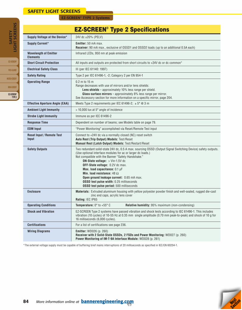
84 More information online at bannerengineering.com
EZ-SCREEN® TYPE 2 Systems
EZ-SCREEN®
PICO-GUARD™
MICRO-SCREEN®
MINI-SCREEN®
SAFE
TYLI
GH
T SC
REE
NS
EZ-SCREEN® TYPE 2
SAFETY LIGHT SCREENS
EZ-SCREEN® Type 2 SpecificationsSupply Voltage at the Device* 24V dc ±20% (PELV)
Supply Current* Emitter: 50 mA max.Receiver: 90 mA max., exclusive of OSSD1 and OSSD2 loads (up to an additional 0.5A each)
Wavelength of Emitter Elements
Infrared LEDs, 950 nm at peak emission
Short Circuit Protection All inputs and outputs are protected from short circuits to +24V dc or dc common*
Electrical Safety Class III (per IEC 61140: 1997)
Safety Rating Type 2 per IEC 61496-1, -2; Category 2 per EN 954-1
Operating Range 0.2 m to 15 mRange decreases with use of mirrors and/or lens shields: Lens shields – approximately 10% less range per shield. Glass-surface mirrors – approximately 8% less range per mirror.See Accessory section for more information on a specific mirror, page 204.
Effective Aperture Angle (EAA) Meets Type 2 requirements per IEC 61496-2; ± 5° @ 3 m
Ambient Light Immunity > 10,000 lux at 5° angle of incidence
Strobe Light Immunity Immune as per IEC 61496-2
Response Time Dependent on number of beams; see Models table on page 79.
EDM Input “Power Monitoring” accomplished via Reset/Remote Test input
Reset Input / Remote Test Input
Connect to +24V dc via a normally closed (NC) reset switchAuto Rest (Trip Output) Models: Test/ResetManual Rest (Latch Output) Models: Test/Restart/Reset
Safety Outputs Two redundant solid-state 24V dc, 0.5 A max. sourcing OSSD (Output Signal Switching Device) safety outputs. (Use optional interface modules for ac or larger dc loads.)Not compatible with the Banner “Safety Handshake.” ON-State voltage: > Vin-1.5V dc OFF-State voltage: 0.2V dc max. Max. load capacitance: 0.1 µF Min. load resistance: 48 Ω Open ground leakage current: 0.65 mA max. OSSD test pulse width: 0.25 milliseconds OSSD test pulse period: 500 milliseconds
Enclosure Materials: Extruded aluminum housing with yellow polyester powder finish and well-sealed, rugged die-cast zinc end caps, acrylic lens cover
Rating: IEC IP65
Operating Conditions Temperature: 0° to +55° C Relative humidity: 95% maximum (non-condensing)
Shock and Vibration EZ-SCREEN Type 2 systems have passed vibration and shock tests according to IEC 61496-1. This includes vibration (10 cycles) of 10-55 Hz at 0.35 mm single amplitude (0.70 mm peak-to-peak) and shock of 10 g for 16 milliseconds (6,000 cycles).
Certifications For a list of certifications see page 236.
Wiring Diagrams Emitter: WD026 (p. 260)Receiver with 2 Solid-State OSSDs, 2 FSDs and Power Monitoring: WD027 (p. 260)Power Monitoring of IM-T-9A Interface Module: WD028 (p. 261)
*The external voltage supply must be capable of buffering brief mains interruptions of 20 milliseconds as specified in IEC/EN 60204-1.