Lifts Elevators Escalators and Moving Walkways Travelators 2DE2
170
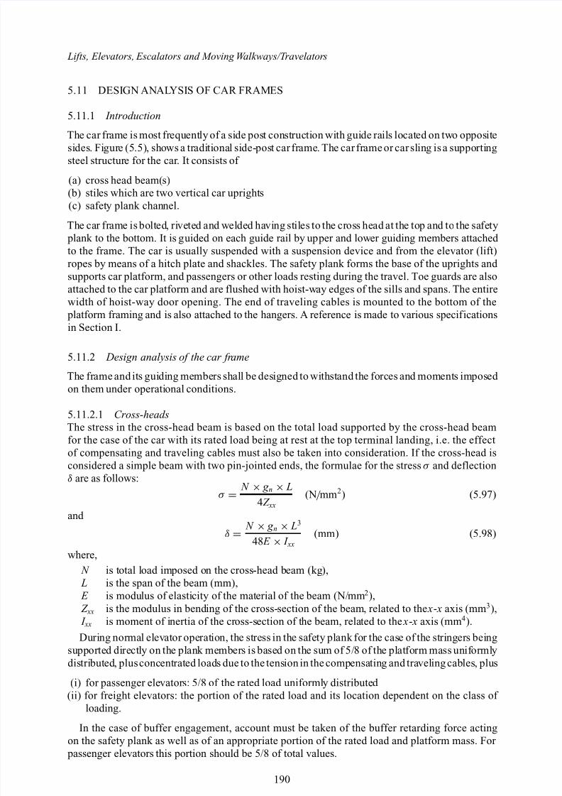
Lifts, Elevators, Escalators and Moving W alkways/T ravelator s 5.11 DESIGN ANAL YSI S OF CAR FRAMES 5.11.1 Introduction The car fr ame is most fr equent ly of a si de pos t const ructi on wi th gui de rail s locat ed on tw o oppos it e sides. Fi gur e (5.5), shows a tradi ti onal side- pos t car frame. The car frame or carsling is a supporti ng steel structur e for the car . It consists of (a) cross head beam( s) (b) stil es which are two vertical car upright s (c) safet y plank chan nel. The car frame is bolt ed , riveted and welded having stiles to the cross head at the top and to the safety plank to the bottom. It is g uided on each guide rail by up per and lower guiding members attached to the frame. The car is usually suspended with a suspension device and from the elevator (lift) ropes by means of a hitch plate and shackles. The safety plank forms the base of the uprights and supports car platform, and passengers or other loads resting during the travel. Toe guards are also attached to the car platform and are flushed with hoist-w ay edges of the sills and spans. The entire width of hoist-way door opening. The end of traveling cables is mounted to the bottom of the platform framing and is also attached to the hangers. A reference is made to various specif ications in Section I. 5.11.2 Design analysis of the car fr ame The fr ame and it s gui di ng membe rs shal l be des igned to wi thst and the forces and moment s impos ed on them under operati onal conditions. 5.11.2.1 Cross-heads The stress in the cross-head beam is based on the total load supported by the cross-head beam for the case of the car with its rated load being at rest at the top terminal landing, i.e. the effect of compensating and traveling cables must also be taken into consideration. If the cross-head is considered a simple beam with two pin-jointed ends, the formulae for the stress σ and deflection δ are as follows: σ = N × g n × L 4Z xx (N / mm 2 ) (5.97) and δ = N × g n × L 3 48 E × I xx (mm) (5.98) where, N is total l oad imposed o n the cross-head b eam (kg ), L is the span of the beam (mm), E is modu lus of elasti city of the mat erial of the beam (N/ mm 2 ), Z xx is the modulus in bending of the cross-section of the beam, related to the x - x axis (mm 3 ), I xx is moment of i nertia of the cr oss-s ection of t he beam, rela ted to the x - x axis (mm 4 ). Duri ng normal el evator ope rat ion, the stress in the safety pl ank for the case of the st ri nger s bei ng supporte d di re ct ly on the pl ank me mber s is based on the sum of 5/8 of the pl at form mass uniformly dis tri but ed , plus conc ent rat ed load s due to the tens ion in the comp ensa ting and tra vel ing cables , plus (i) for passenger ele vator s: 5/8 of the rated load uniforml y distribute d (ii) for freight elevators: the portion of the rated load and its location dependent on the class of loading. In the case of buffer engagement, account must be taken of the buffer retarding force acting on the safety plank as well as of an appropriate portion of the rated load and platform mass. For passenger elevators this portion should be 5/8 of total values. 190
-
Upload
jvicec8260 -
Category
Documents
-
view
217 -
download
0
Transcript of Lifts Elevators Escalators and Moving Walkways Travelators 2DE2
8/10/2019 Lifts Elevators Escalators and Moving Walkways Travelators 2DE2
http://slidepdf.com/reader/full/lifts-elevators-escalators-and-moving-walkways-travelators-2de2 1/169
Lifts, Elevators, Escalators and Moving Walkways/Travelators
5.11 DESIGN ANALYSIS OF CAR FRAMES
5.11.1 Introduction
The car frame is most frequently of a side post construction with guide rails located on two oppositesides. Figure (5.5), shows a traditional side-post car frame. The car frame or car sling is a supportingsteel structure for the car. It consists of
(a) cross head beam(s)(b) stiles which are two vertical car uprights(c) safety plank channel.
The car frame is bolted, riveted and welded having stiles to the cross head at the top and to the safety plank to the bottom. It is guided on each guide rail by upper and lower guiding members attached to the frame. The car is usually suspended with a suspension device and from the elevator (lift)ropes by means of a hitch plate and shackles. The safety plank forms the base of the uprights and
supports car platform, and passengers or other loads resting during the travel. Toe guards are alsoattached to the car platform and are flushed with hoist-way edges of the sills and spans. The entirewidth of hoist-way door opening. The end of traveling cables is mounted to the bottom of the platform framing and is also attached to the hangers. A reference is made to various specificationsin Section I.
5.11.2 Design analysis of the car frame
The frame and its guiding members shall be designed to withstand the forces and moments imposed on them under operational conditions.
5.11.2.1 Cross-headsThe stress in the cross-head beam is based on the total load supported by the cross-head beamfor the case of the car with its rated load being at rest at the top terminal landing, i.e. the effectof compensating and traveling cables must also be taken into consideration. If the cross-head isconsidered a simple beam with two pin-jointed ends, the formulae for the stress σ and deflectionδ are as follows:
σ = N × g n × L
4Z xx(N/ mm 2) (5.97)
and
δ = N × g n × L3
48 E × I xx(mm) (5.98)
where, N is total load imposed on the cross-head beam (kg), L is the span of the beam (mm), E is modulus of elasticity of the material of the beam (N/mm 2),Z xx is the modulus in bending of the cross-section of the beam, related to the x- x axis (mm 3), I xx is moment of inertia of the cross-section of the beam, related to the x- x axis (mm 4).During normal elevator operation, the stress in the safety plank for the case of the stringers being
supported directly on the plank members is based on the sum of 5/8 of the platform mass uniformlydistributed, plusconcentrated loads due to the tension in the compensating and traveling cables, plus
(i) for passenger elevators: 5/8 of the rated load uniformly distributed
(ii) for freight elevators: the portion of the rated load and its location dependent on the class of loading.
In the case of buffer engagement, account must be taken of the buffer retarding force actingon the safety plank as well as of an appropriate portion of the rated load and platform mass. For passenger elevators this portion should be 5/8 of total values.
190
8/10/2019 Lifts Elevators Escalators and Moving Walkways Travelators 2DE2
http://slidepdf.com/reader/full/lifts-elevators-escalators-and-moving-walkways-travelators-2de2 2/169
Design analysis of lift elements and components
The buffer retarding force, acting as a concentrated load, is generally given by the formula:
F = (Q + M ) × ( g n + αmax ) (5.99)
where,α max is maximum retardation due to the buffer engagement, lasting for more than
0.04s (m/s 2).For oil buffer engagement, the stress σ is:
σ = (Q + M ) g n × d
2Z xx(N/ mm 2) (5.100)
For stiles under combined tensioned and compression, the value of a critical stress σ cr is given byEquation (5.101):
σ cr = N × g n2 A + ML
4 H · Z xx(N/ mm 2) (5.101)
where, A =cross-sectional area of uprights on one side (mm) M =turning moment L =free length of an upright N =loading H =distance between the centre of upper and lower guide shoes (mm)Z xx =modulus in bendinge =eccentricity of the load in plane of guide rails
M = Q · g n · e (5.102)
For CLASS A Passenger or general freight loading:
M = Qg nb
8(5.103)
For CLASS B Loading
M = Qg nb
8(5.104)
or
M = Qg nb2 − 1220 (5.105)
For CLASS C Loading
M = 2Qg nb
8(5.106)
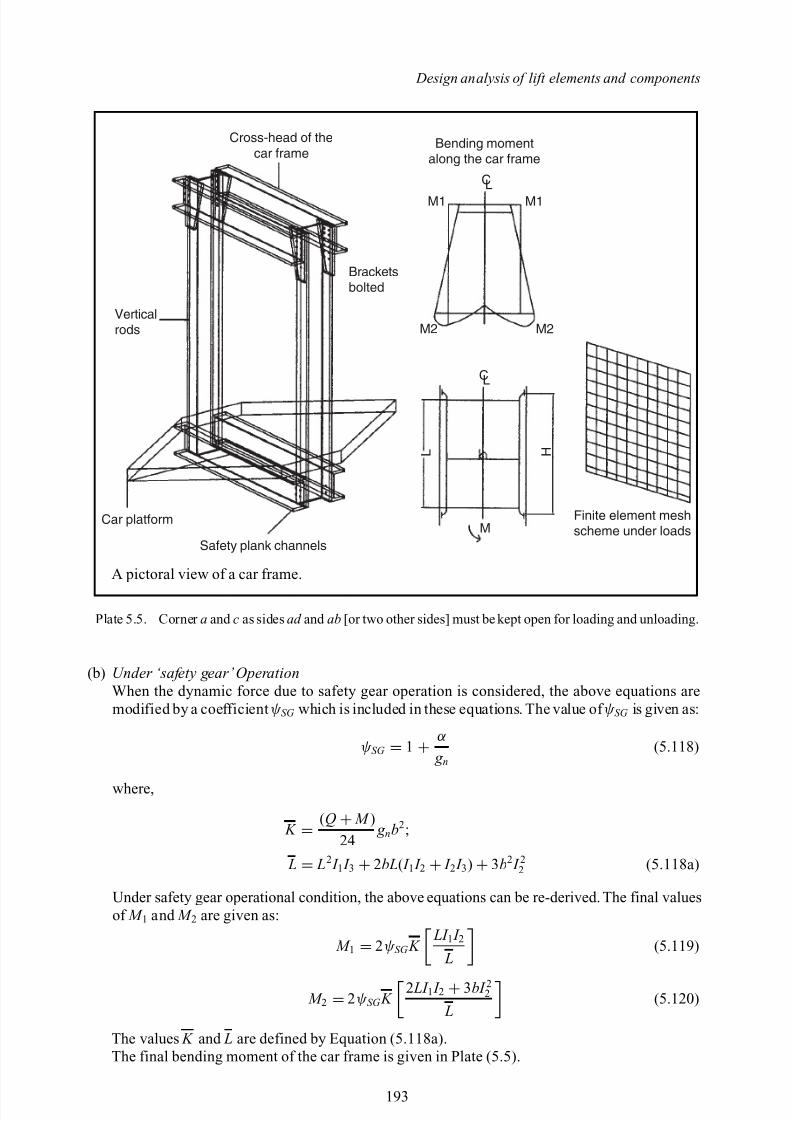
5.11.2.2 Distortion of frame parts under loadsPlate (5.5) shows various forces and moments occurring on the frame.
(1) Under concentrated load ( Q
+ M ) g n acting concentrically
θ = angle of distortion of the cross-head
= −(Q + M ) g nb2
16 EI 1(5.107)
191
8/10/2019 Lifts Elevators Escalators and Moving Walkways Travelators 2DE2
http://slidepdf.com/reader/full/lifts-elevators-escalators-and-moving-walkways-travelators-2de2 3/169
Lifts, Elevators, Escalators and Moving Walkways/Travelators
(2) If the concentrated load Q is off centre i.e. placed at m and n distance from one end
θ 1 = − Qg nn6bEI 1
(b2 − n2) (5.108)
θ 2 = −Qg nm × n(b + m)
6bEI 1(5.109)
(3) Safety plank under uniform load ‘ ω’ the load is:
ω = (Q + M ) g n
b(5.110)
θ sp = (Q + M ) g nb2
24 EI 3(5.111)
(4) Two moments M 1 applied at the ends of the cross-head or top of the car:
θ 1 = + M 1b2 EI 1
(5.112)
If one end carries M 1
θ 1 = + M 1b6 EI 1
(a) Under normal operation conditionsRated load uniformly distributed on the car floor area.Inner moments at the ends of the safety plank are M 2 .
Equation of EquilibriumThe angles of distortion at say node (1), the inner moment M 1 , at (1) of the cross-head and thestile or an upright at (1).
−θ + θ 1
cross -head = − rotation due M 1 of upright at (1)
− rotation due to M 2 at node (1) upper end of the upright
− (Q + M ) g nb2
16 EI 1 + M 1 L3 EI 2 = −
M 1 L3 EI 2 −
M 2 L6 EI 2
(5.113)
Inner moment M 2 involving angles of distortion of plank at bottom and the bottom end of theupright:
θ sp
plank
− M 2b2 EI 2
fromplank
= M 2b2 EI 2 +
M 1 L6 EI 2
upright
(5.114)
Solving Equations (5.113) and (5.114) for M 1 and M 2 , the final values are given as:
M 1 = K 6 LI 2 I 3 + 9bI 22 − 2 LI 1 I 2
L (5.115)
M 2 = K
4 LI 2 I 3
+ 6bI 22
− 2 LI 1 I 3
L (5.116)R =the horizontal reactions are computed as Equation (5.117):
R = M 1 + M 2
L(5.117)
192
8/10/2019 Lifts Elevators Escalators and Moving Walkways Travelators 2DE2
http://slidepdf.com/reader/full/lifts-elevators-escalators-and-moving-walkways-travelators-2de2 4/169
Design analysis of lift elements and components
Cross-head of thecar frame
Bending momentalong the car frame
M1
M2 M2
M1
Bracketsbolted
Car platform
Safety plank channelsM
Finite element meshscheme under loads
C
L H
Verticalrods
L
CL
A pictoral view of a car frame.
Plate 5.5. Corner a and c as sides ad and ab [or two other sides] must be kept open for loading and unloading.
(b) Under ‘safety gear’OperationWhen the dynamic force due to safety gear operation is considered, the above equations aremodified by a coefficient ψ SG which is included in these equations. The value of ψ SG is given as:
ψ SG = 1 + α g n
(5.118)
where,
K = (Q + M )
24 g nb2 ;
L = L2 I 1 I 3 + 2bL( I 1 I 2 + I 2 I 3) + 3b2 I 22 (5.118a)
Under safety gear operational condition, the above equations can be re-derived. The final valuesof M 1 and M 2 are given as:
M 1 = 2ψ SG K LI 1 I 2
L (5.119)
M 2 = 2ψ SG K 2 LI 1 I 2 + 3bI 22
L (5.120)
The values K and L are defined by Equation (5.118a).The final bending moment of the car frame is given in Plate (5.5).
193
8/10/2019 Lifts Elevators Escalators and Moving Walkways Travelators 2DE2
http://slidepdf.com/reader/full/lifts-elevators-escalators-and-moving-walkways-travelators-2de2 5/169
Lifts, Elevators, Escalators and Moving Walkways/Travelators
5.12 DOORS AND DOOR DYNAMICS
5.12.1 Introduction
The selection depends upon convenient type of car and landing, kind of elevators and its rated load.In addition the simultaneous transfer of passengers within the door width in shortest opening and closing time can be treated as an efficient door. Normally as stated earlier in Section 1 the normalwidth of the door shall be at least equal to or greater than 1100 mm. In compliance with EN 81.1the following conditions are satisfied.
(1) the rated speed does not exceed 0.63 m/sec(2) the depth of the car is greater then 1.5 m(3) the edge of the car operating panel is at least 0.4 m from the car entrance.
The conditions for the strength of the door panels vary slightly with different standards. Inaccordance with EN 81.1 the doors in the locked position shall be subjected to a force of 300N at
right angles the panel evenly distributed over an area of 500 mm and must(a) resist without permanent deformation(b) resist elastic deformations greater than 15 mm(c) operate satisfactorily after such a test.
There are many types of car doors. The doors are classified as
(i) swinging doors(ii) horizontally sliding doors
(iii) vertical sliding doors(iv) multi-panel doors.
5.13 DOOR DYNAMICS
The EN81 and USA17.1 standards prescribe that the kinetic energy of the power operated liftor elevator car and landing doors must not exceed 10 Joules (EN81) and 9.5 Joules (USA17.1) provided that the reopening exists.
5.13.1 Kinetic energy of the doors
The kinetic energy value is reduced to 4.0 J {3.4 J }, if the re-opening device is disabled (eg. Duringnudging).
Kinetic energy ( KE ) is given by:
KE = 12 M ν2
d (5.121)
where, M is the weight of the doors (kg)ν2
d is the maximum speed (m/s) that the doors attain.
Table (5.1) gives the maximum speed that the elevator doors are permitted to attain, when closing.
5.13.2 Door closure force
The force necessary to prevent a door closing may not exceed 150 N {133 N}. The measurement
should be made near the mid point of the door travel.
5.13.3 Doors closed under continuous control
When doors are closed by the user continuously pressing a control button, the fastest panel speed may not exceed 0.3 m/s.
194
8/10/2019 Lifts Elevators Escalators and Moving Walkways Travelators 2DE2
http://slidepdf.com/reader/full/lifts-elevators-escalators-and-moving-walkways-travelators-2de2 6/169
Design analysis of lift elements and components
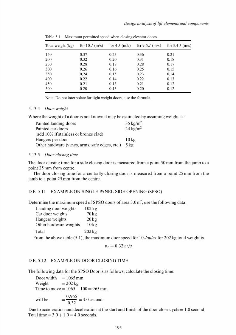
Table 5.1. Maximum permitted speed when closing elevator doors.
Total weight (kg) for 10 J (m/s) for 4 J (m/s) for 9.5 J (m/s) for 3.4 J (m/s)
150 0.37 0.23 0.36 0.21200 0.32 0.20 0.31 0.18250 0.28 0.18 0.28 0.17300 0.26 0.16 0.25 0.15350 0.24 0.15 0.23 0.14400 0.22 0.14 0.22 0.13450 0.21 0.13 0.21 0.12500 0.20 0.13 0.20 0.12
Note: Do not interpolate for light weight doors, use the formula.
5.13.4 Door weight
Where the weight of a door is not known it may be estimated by assuming weight as:Painted landing doors 35 kg/m 2
Painted car doors 24 kg/m 2
(add 10% if stainless or bronze clad)Hangers per door 10 kgOther hardware (vanes, arms, safe edges, etc.) 5 kg
5.13.5 Door closing time
The door closing time for a side closing door is measured from a point 50 mm from the jamb to a point 25 mm from centre.
The door closing time for a centrally closing door is measured from a point 25 mm from the jamb to a point 25 mm from the centre.
D.E. 5.11 EXAMPLE ON SINGLE PANEL SIDE OPENING (SPSO)
Determine the maximum speed of SPSO doors of area 3.0 m 2 , use the following data:Landing door weights 102 kgCar door weights 70 kgHangers weights 20 kgOther hardware weights 10 kg
Total 202 kgFrom the above table (5.1), the maximum door speed for 10 Joules for 202 kg total weight is
νd = 0.32 m/ s
D.E. 5.12 EXAMPLE ON DOOR CLOSING TIME
The following data for the SPSO Door is as follows, calculate the closing time:Door width =1065 mmWeight =202 kgTime to move
=1065
−100
=965 mm
will be = 0.965
0.32 =3.0 seconds
Due to acceleration and deceleration at the start and finish of the door close cycle =1.0 second Total time =3.0 +1.0 =4.0 seconds.
195

8/10/2019 Lifts Elevators Escalators and Moving Walkways Travelators 2DE2
http://slidepdf.com/reader/full/lifts-elevators-escalators-and-moving-walkways-travelators-2de2 7/169
8/10/2019 Lifts Elevators Escalators and Moving Walkways Travelators 2DE2
http://slidepdf.com/reader/full/lifts-elevators-escalators-and-moving-walkways-travelators-2de2 8/169
6
Lift/Elevator travel analysis
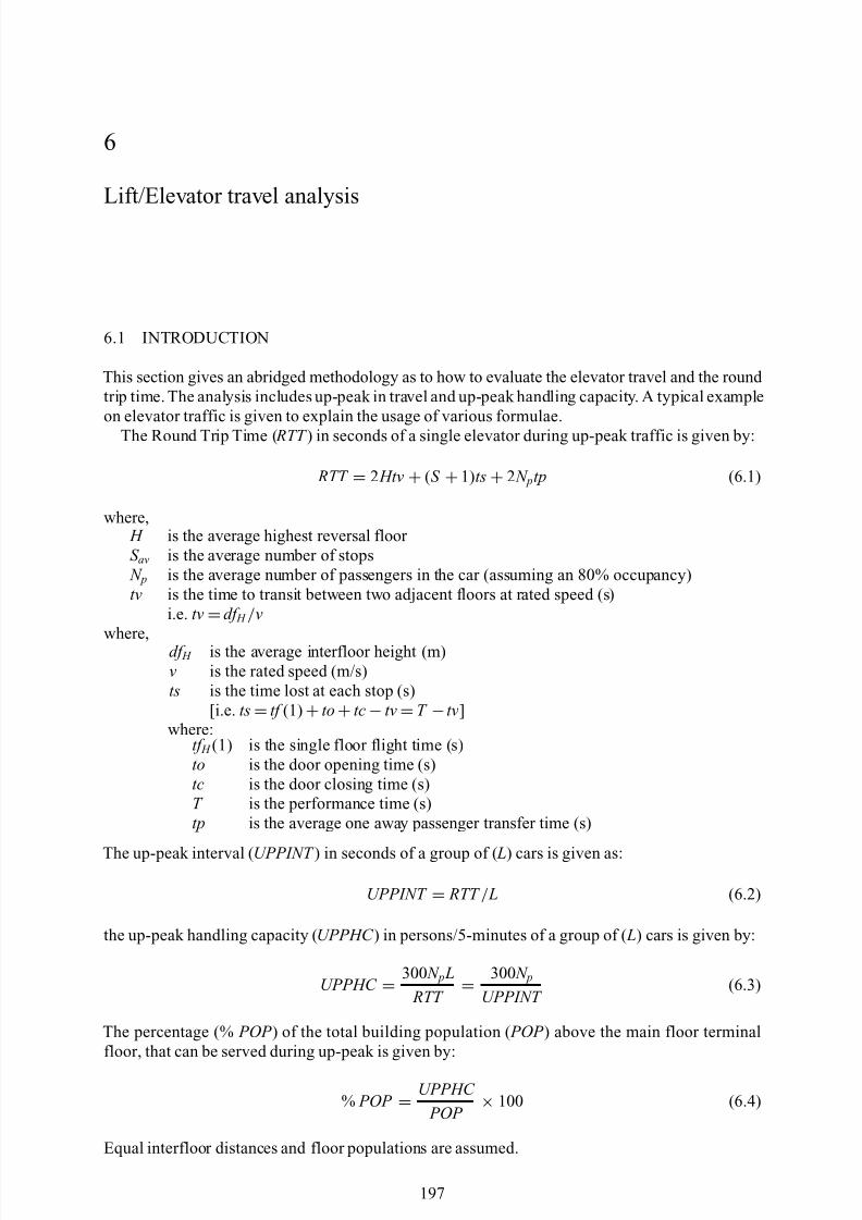
6.1 INTRODUCTION
This section gives an abridged methodology as to how to evaluate the elevator travel and the round trip time. The analysis includes up-peak in travel and up-peak handling capacity. A typical exampleon elevator traffic is given to explain the usage of various formulae.
The Round Trip Time ( RTT ) in seconds of a single elevator during up-peak traffic is given by:
RTT = 2 Htv + (S + 1)ts + 2 N ptp (6.1)
where, H is the average highest reversal floor S av is the average number of stops N p is the average number of passengers in the car (assuming an 80% occupancy)tv is the time to transit between two adjacent floors at rated speed (s)
i.e. tv =df H / v
where, df H is the average interfloor height (m)v is the rated speed (m/s)ts is the time lost at each stop (s)
[i.e. ts =tf (1) +to +tc −tv =T −tv]where:
tf H (1) is the single floor flight time (s)to is the door opening time (s)tc is the door closing time (s)T is the performance time (s)tp is the average one away passenger transfer time (s)
The up-peak interval ( UPPINT ) in seconds of a group of ( L) cars is given as:
UPPINT = RTT / L (6.2)
the up-peak handling capacity ( UPPHC ) in persons/5-minutes of a group of ( L) cars is given by:
UPPHC = 300 N p L
RTT = 300 N pUPPINT
(6.3)
The percentage (% POP ) of the total building population ( POP ) above the main floor terminalfloor, that can be served during up-peak is given by:
% POP = UPPHC
POP × 100 (6.4)
Equal interfloor distances and floor populations are assumed.
197
8/10/2019 Lifts Elevators Escalators and Moving Walkways Travelators 2DE2
http://slidepdf.com/reader/full/lifts-elevators-escalators-and-moving-walkways-travelators-2de2 9/169
Lifts, Elevators, Escalators and Moving Walkways/Travelators
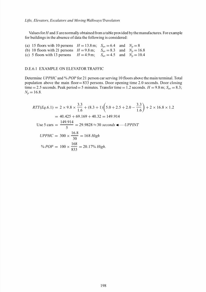
Values for H and S arenormally obtained from a table provided by the manufactures. For examplefor buildings in the absence of data the following is considered:
(a) 15 floors with 10 persons H =13.8 m; S av =6.4 and N p =8
(b) 10 floors with 21 persons H =9.8 m; S av =8.3 and N p =16.8(c) 5 floors with 13 persons H =4.9 m; S av =4.5 and N p =10.4
D.E.6.1 EXAMPLE ON ELEVATOR TRAFFIC
Determine UPPHC and % POP for 21 person car serving 10 floors above the main terminal. Total population above the main floor =833 persons. Door opening time 2.0 seconds. Door closingtime =2.5 seconds. Peak period =5 minutes. Transfer time =1.2 seconds. H =9.8 m; S av =8.3; N p =16.8.
RTT ( Eq.6.1) = 2 × 9.8 × 3.31.6 + (8.3 + 1) 5.0 + 2.5 + 2.0 −
3.31.6 + 2 × 16.8 × 1.2
= 40.425 + 69.169 + 40.32 = 149 .914
Use 5 cars = 149 .914
5 = 29 .9828 ≈30 seconds —– UPPINT
UPPHC = 300 × 16.8
30 = 168 High
% POP = 100 × 168833 = 20 .17% High .
198
8/10/2019 Lifts Elevators Escalators and Moving Walkways Travelators 2DE2
http://slidepdf.com/reader/full/lifts-elevators-escalators-and-moving-walkways-travelators-2de2 10/169
7
Maximum and minimum stopping distances of car and counterweight (Based on US-A17.1)
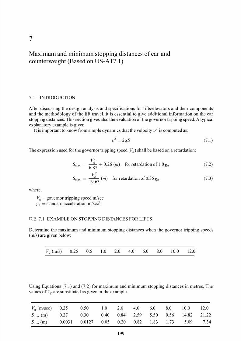
7.1 INTRODUCTION
After discussing the design analysis and specifications for lifts/elevators and their componentsand the methodology of the lift travel, it is essential to give additional information on the car
stopping distances. This section gives also the evaluation of the governor tripping speed. A typicalexplanatory example is given.
It is important to know from simple dynamics that the velocity υ 2 is computed as:
υ 2 = 2αS (7.1)
The expression used for the governor tripping speed ( V g ) shall be based on a retardation:
S max =V 2 g
6.87 + 0.26 (m) for retardation of 1 .0 g n (7.2)
S max =V 2 g
19 .63 (m) for retardation of 0 .35 g n (7.3)
where,
V g =governor tripping speed m/sec g n =standard acceleration m/sec 2 .
D.E. 7.1 EXAMPLE ON STOPPING DISTANCES FOR LIFTS
Determine the maximum and minimum stopping distances when the governor tripping speeds(m/s) are given below:
V g (m/s) 0.25 0.5 1.0 2.0 4.0 6.0 8.0 10.0 12.0
Using Equations (7.1) and (7.2) for maximum and minimum stopping distances in metres. Thevalues of V g are substituted as given in the example.
V g (m/sec) 0.25 0.50 1.0 2.0 4.0 6.0 8.0 10.0 12.0
S max (m) 0.27 0.30 0.40 0.84 2.59 5.50 9.56 14.82 21.22
S min (m) 0.0031 0.0127 0.05 0.20 0.82 1.83 1.73 5.09 7.34
199

8/10/2019 Lifts Elevators Escalators and Moving Walkways Travelators 2DE2
http://slidepdf.com/reader/full/lifts-elevators-escalators-and-moving-walkways-travelators-2de2 11/169
8/10/2019 Lifts Elevators Escalators and Moving Walkways Travelators 2DE2
http://slidepdf.com/reader/full/lifts-elevators-escalators-and-moving-walkways-travelators-2de2 12/169
8
Elements of super structures – Finite Element Analysis
8.1 BELT CALCULATIONS
Prior to any belting calculation being carried out it is necessary to establish:
1. the output to be conveyed;2. the profile of the conveyor(s); and 3. the approximate density of the mineral to be conveyed.
When these data are available it is then possible to determine:
4. the belt width and belt speed;5. total horsepower required;6. type of drive unit;7. tensile strength of belt necessary; and 8. the correct belt type for the installation.
8.1.1 Belt capacity
A comprehensive analysis for the belt capacity is given in chapter 4.When determining the belt width and belt speed the following should be taken into account:
(a) Belt types 10 and 12 will only through and track at the lower throughing angles, i.e.approximately 20;
(b) There is a danger with deep throughing (i.e. 45 ◦) that the stresses produced in the belt carcassat the transition area between the wing and centre idlers will cause premature belt failure;
(c) The size of the roadway or gantry may restrict the choice of belt width;(d) An increase in belt speed increases the rate of wear of the moving parts and increases the
emission of dust at the transfer points.
A length correction factor is generally included, which gives the power required to drive theempty belt and to convey the material only, and is based on the use of ball or roller bearing equip-ment throughout. The frictional factors expressed may appear to be unnecessarily conservativehaving regard to the f igures derived from laboratory tests but experience has proved their depend-ability, particularly in view of the effects of dust, water, slimes and other factors that have to beaccommodated underground; i.e. tables have been derived from a combination of pit experience aswell as mathematics.
The power required to drive the empty belt is derived as follows:
Horse power
=
K x LCWSF
884× E
(8.1)
where, K x = 0.03 L = Length of conveyor in feet (1ft =0.3048 m)C = Coefficient of friction.
201
8/10/2019 Lifts Elevators Escalators and Moving Walkways Travelators 2DE2
http://slidepdf.com/reader/full/lifts-elevators-escalators-and-moving-walkways-travelators-2de2 13/169
Lifts, Elevators and moving walkways/Travelators
8.2 FINITE ELEMENT ANALYSIS
A reference is made to the generalised analysis and computed subroutines given in Appendix I and Appendix III. Here some finite element mesh schemes are given for specific parts of the stressanalysis of the travelators. They are listed below.
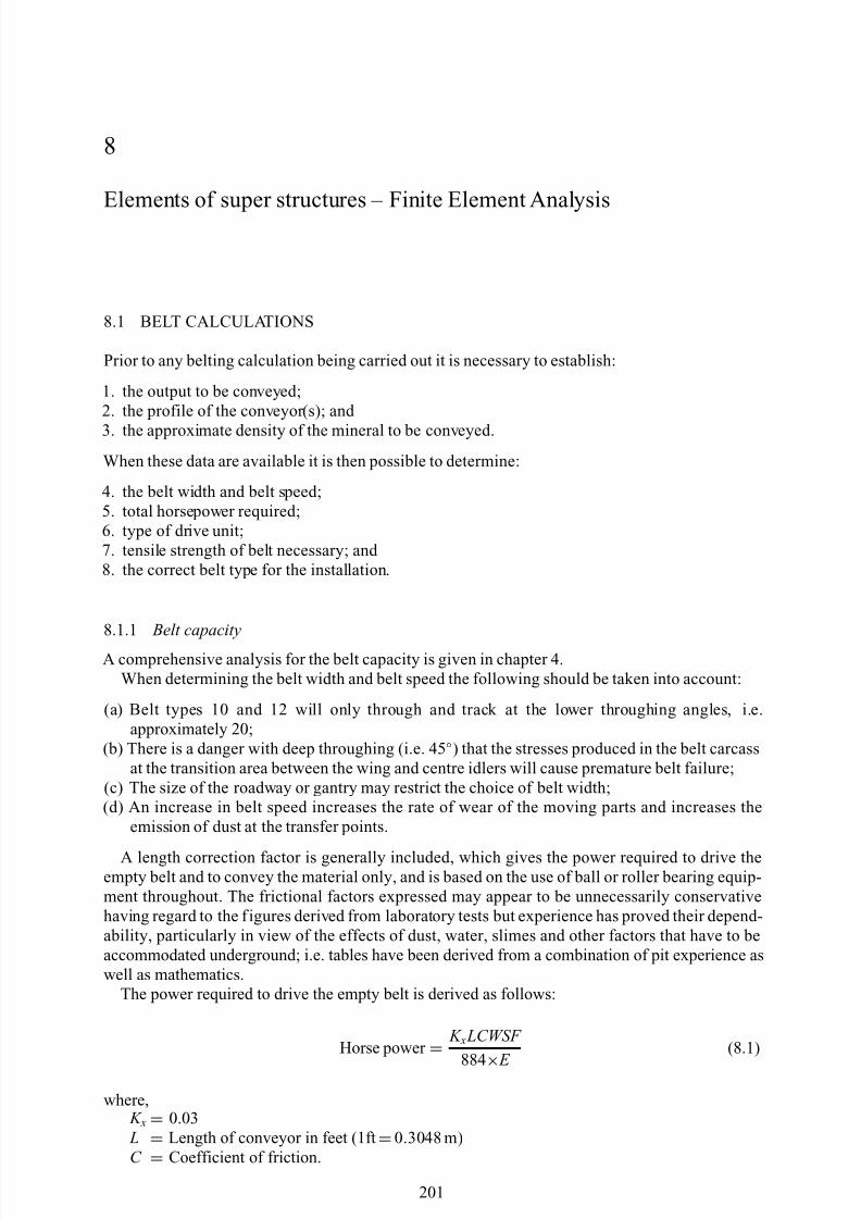
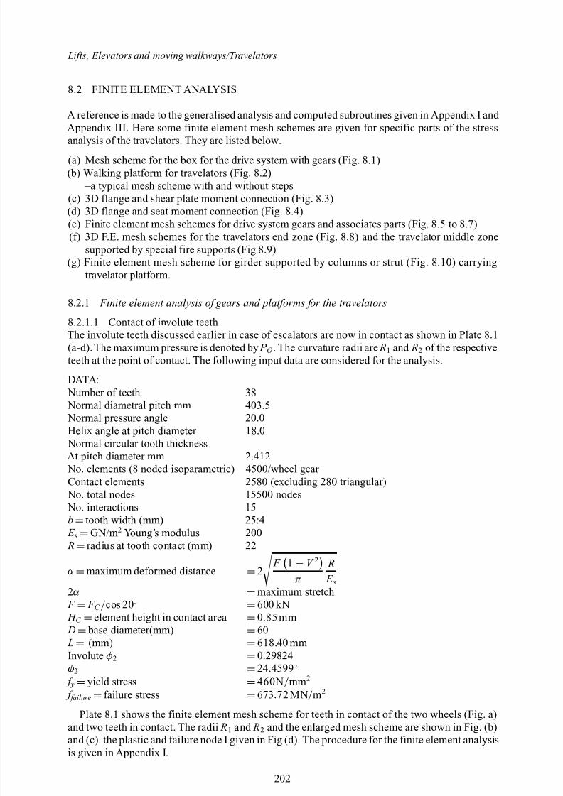
(a) Mesh scheme for the box for the drive system with gears (Fig. 8.1)(b) Walking platform for travelators (Fig. 8.2)
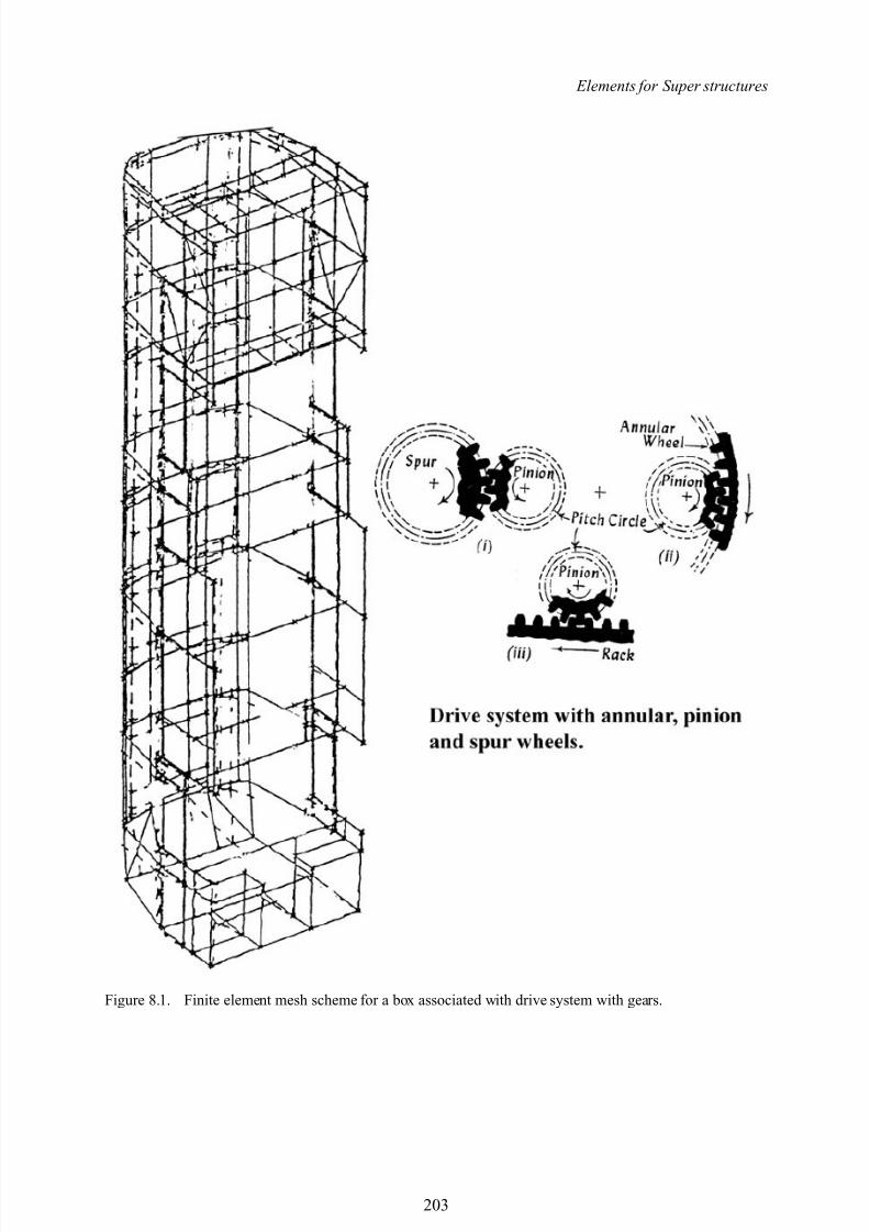
–a typical mesh scheme with and without steps(c) 3D flange and shear plate moment connection (Fig. 8.3)(d) 3D flange and seat moment connection (Fig. 8.4)(e) Finite element mesh schemes for drive system gears and associates parts (Fig. 8.5 to 8.7)(f) 3D F.E. mesh schemes for the travelators end zone (Fig. 8.8) and the travelator middle zone
supported by special fire supports (Fig 8.9)(g) Finite element mesh scheme for girder supported by columns or strut (Fig. 8.10) carrying
travelator platform.
8.2.1 Finite element analysis of gears and platforms for the travelators
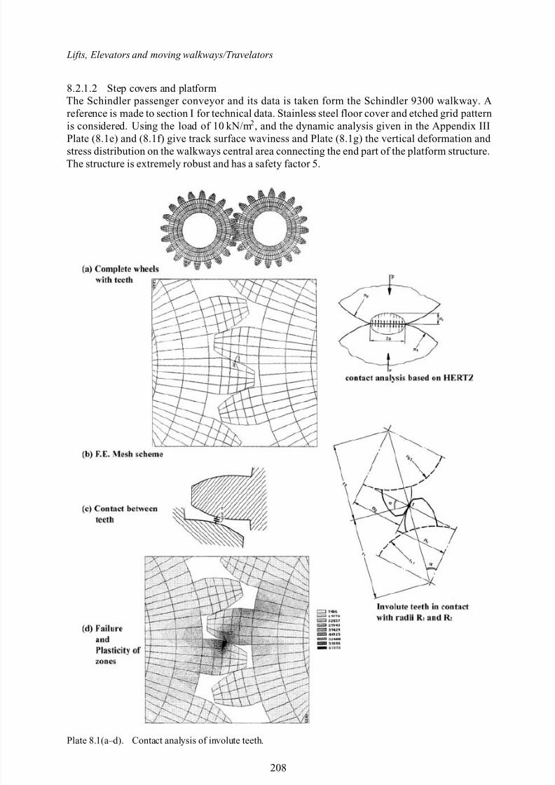
8.2.1.1 Contact of involute teethThe involute teeth discussed earlier in case of escalators are now in contact as shown in Plate 8.1(a-d). The maximum pressure is denoted by P O . The curvature radii are R1 and R2 of the respectiveteeth at the point of contact. The following input data are considered for the analysis.
DATA: Number of teeth 38 Normal diametral pitch mm 403.5
Normal pressure angle 20.0Helix angle at pitch diameter 18.0 Normal circular tooth thicknessAt pitch diameter mm 2.412 No. elements (8 noded isoparametric) 4500/wheel gear Contact elements 2580 (excluding 280 triangular) No. total nodes 15500 nodes No. interactions 15b =tooth width (mm) 25:4 E s =GN/m 2 Young’s modulus 200 R
=radius at tooth contact (mm) 22
α =maximum deformed distance =2 F 1 − V 2
π R E s
2α =maximum stretch F = F C / cos 20 ◦ =600 kN H C =element height in contact area =0.85 mm D = base diameter(mm) =60 L= (mm ) =618.40 mmInvolute φ2 =0.29824φ2 =24 .4599 ◦ f y =yield stress =460N / mm 2
f failure =failure stress =673 .72 MN / m2
Plate 8.1 shows the finite element mesh scheme for teeth in contact of the two wheels (Fig. a)and two teeth in contact. The radii R1 and R2 and the enlarged mesh scheme are shown in Fig. (b)and (c). the plastic and failure node I given in Fig (d). The procedure for the finite element analysisis given in Appendix I.
202
8/10/2019 Lifts Elevators Escalators and Moving Walkways Travelators 2DE2
http://slidepdf.com/reader/full/lifts-elevators-escalators-and-moving-walkways-travelators-2de2 14/169
Elements for Super structures
Figure 8.1. Finite element mesh scheme for a box associated with drive system with gears.
203
8/10/2019 Lifts Elevators Escalators and Moving Walkways Travelators 2DE2
http://slidepdf.com/reader/full/lifts-elevators-escalators-and-moving-walkways-travelators-2de2 15/169
Lifts, Elevators and moving walkways/Travelators
Figure 8.2. Walking platform.
Figure 8.3. Flange and shear plate moment connection – 3D ANSYS mesh scheme.
204
8/10/2019 Lifts Elevators Escalators and Moving Walkways Travelators 2DE2
http://slidepdf.com/reader/full/lifts-elevators-escalators-and-moving-walkways-travelators-2de2 16/169
Elements for Super structures
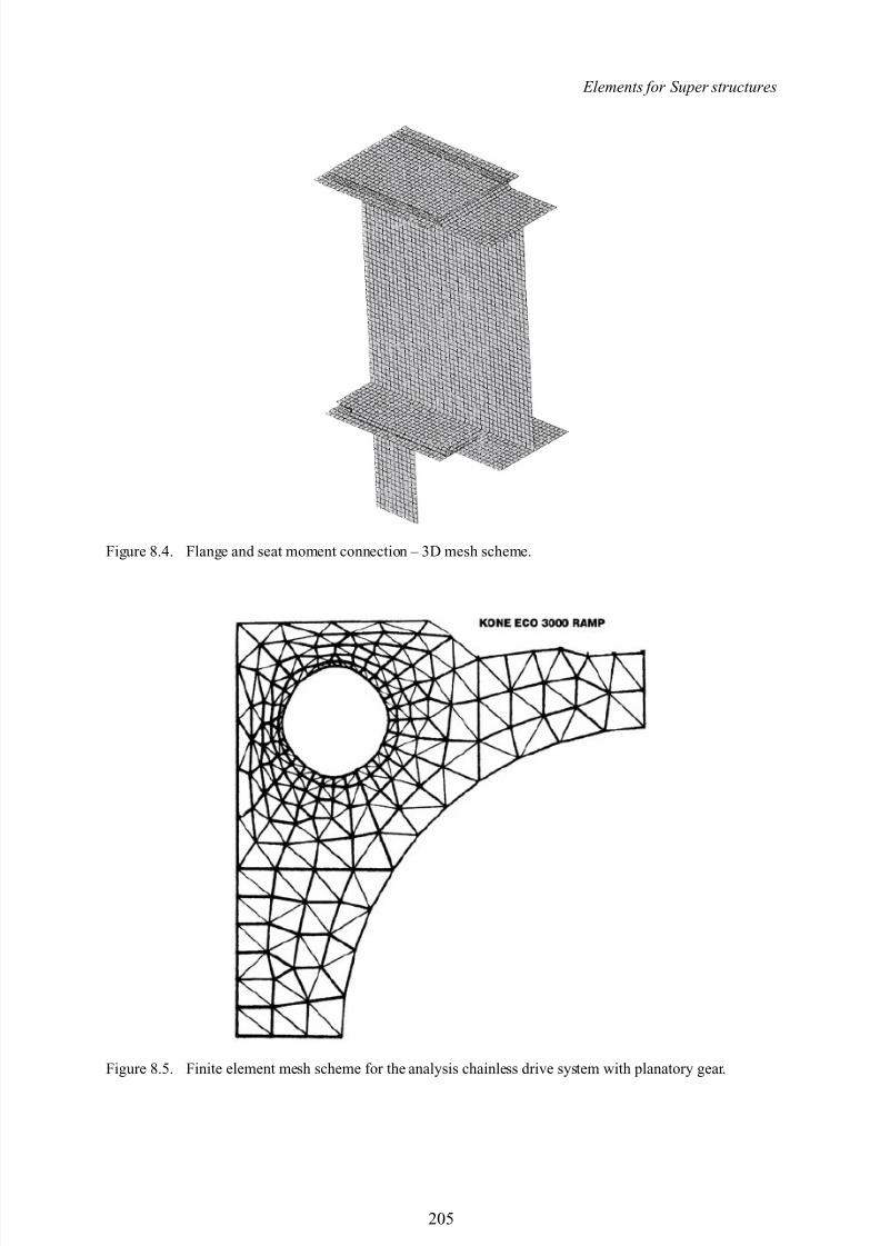
Figure 8.4. Flange and seat moment connection – 3D mesh scheme.
Figure 8.5. Finite element mesh scheme for the analysis chainless drive system with planatory gear.
205
8/10/2019 Lifts Elevators Escalators and Moving Walkways Travelators 2DE2
http://slidepdf.com/reader/full/lifts-elevators-escalators-and-moving-walkways-travelators-2de2 17/169
Lifts, Elevators and moving walkways/Travelators
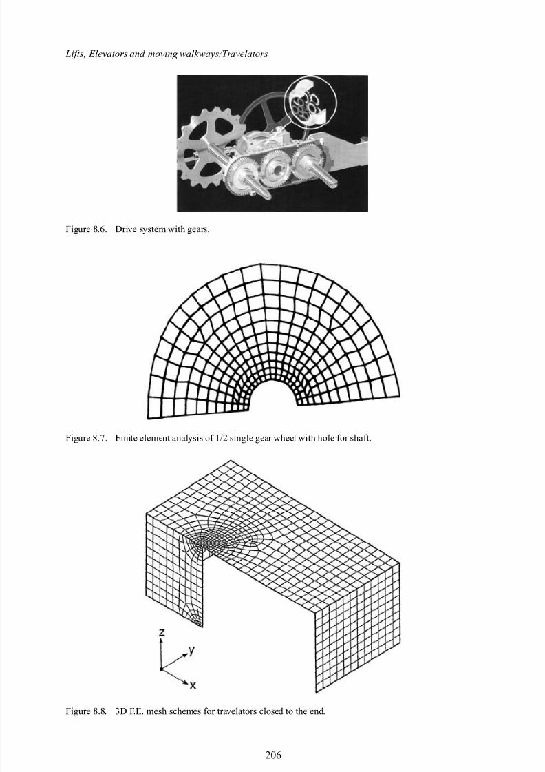
Figure 8.6. Drive system with gears.
Figure 8.7. Finite element analysis of 1/2 single gear wheel with hole for shaft.
Figure 8.8. 3D F.E. mesh schemes for travelators closed to the end.
206
8/10/2019 Lifts Elevators Escalators and Moving Walkways Travelators 2DE2
http://slidepdf.com/reader/full/lifts-elevators-escalators-and-moving-walkways-travelators-2de2 18/169
Elements for Super structures
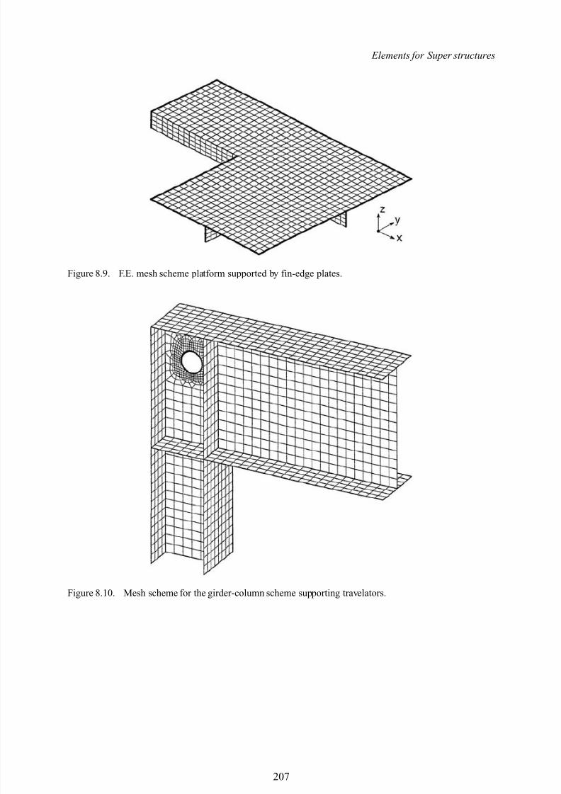
Figure 8.9. F.E. mesh scheme platform supported by fin-edge plates.
Figure 8.10. Mesh scheme for the girder-column scheme supporting travelators.
207
8/10/2019 Lifts Elevators Escalators and Moving Walkways Travelators 2DE2
http://slidepdf.com/reader/full/lifts-elevators-escalators-and-moving-walkways-travelators-2de2 19/169
Lifts, Elevators and moving walkways/Travelators
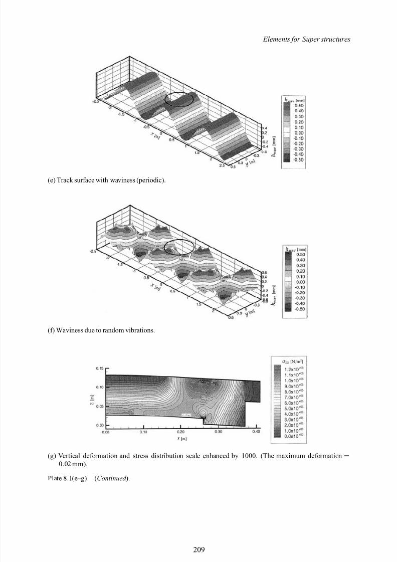
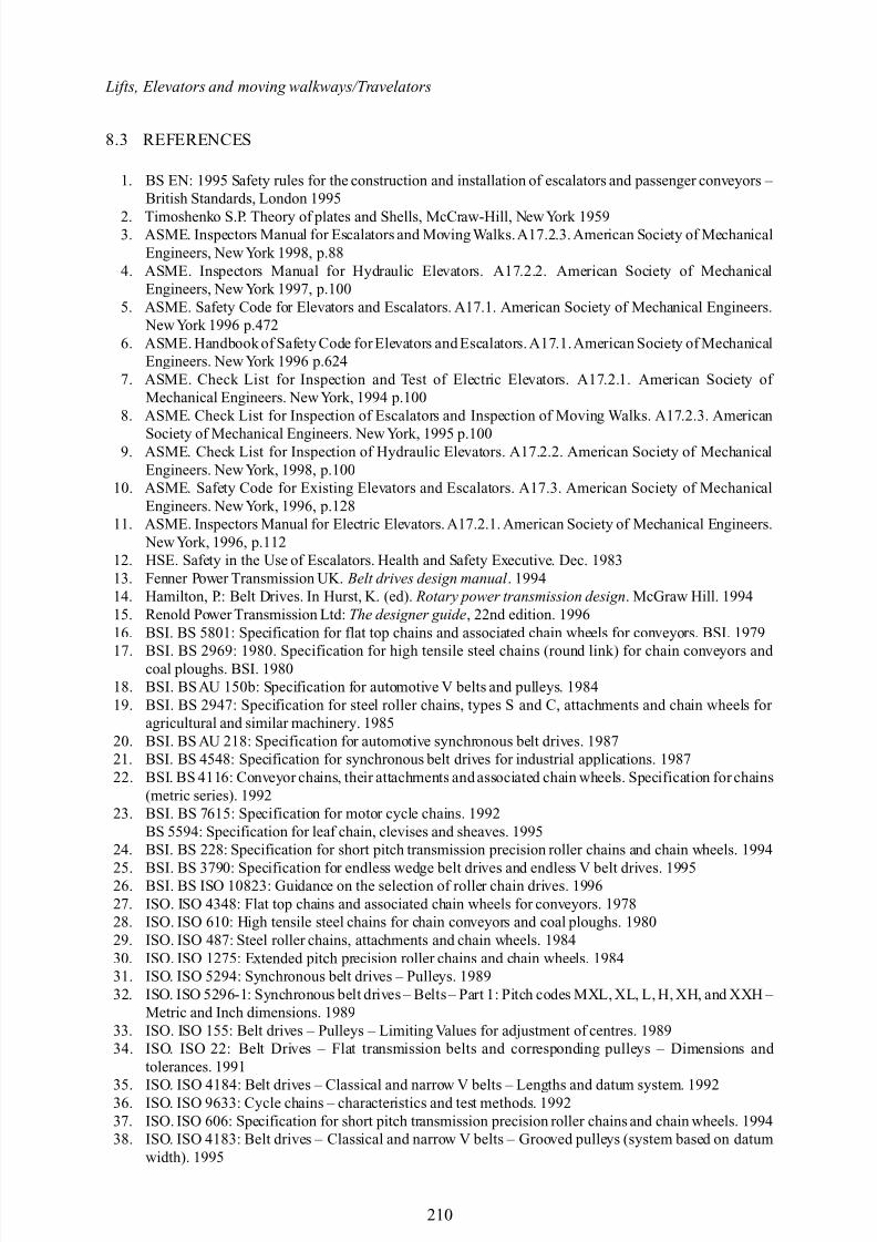
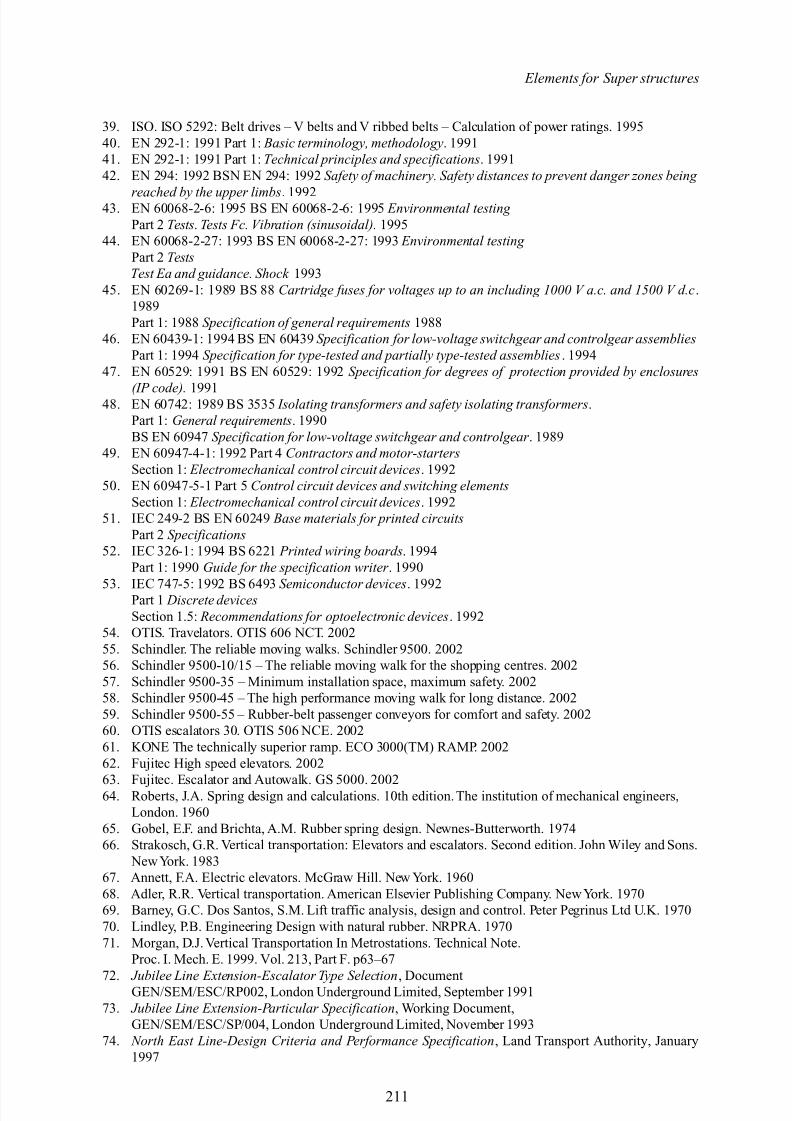
8.2.1.2 Step covers and platformThe Schindler passenger conveyor and its data is taken form the Schindler 9300 walkway. Areference is made to section I for technical data. Stainless steel floor cover and etched grid patternis considered. Using the load of 10 kN/m 2 , and the dynamic analysis given in the Appendix IIIPlate (8.1e) and (8.1f) give track surface waviness and Plate (8.1g) the vertical deformation and stress distribution on the walkways central area connecting the end part of the platform structure.The structure is extremely robust and has a safety factor 5.
Plate 8.1(a–d). Contact analysis of involute teeth.
208
8/10/2019 Lifts Elevators Escalators and Moving Walkways Travelators 2DE2
http://slidepdf.com/reader/full/lifts-elevators-escalators-and-moving-walkways-travelators-2de2 20/169
Elements for Super structures
(e) Track surface with waviness (periodic).
(f) Waviness due to random vibrations.
(g) Vertical deformation and stress distribution scale enhanced by 1000. (The maximum deformation =0.02 mm).
Plate 8.1(e–g). ( Continued ).
209
8/10/2019 Lifts Elevators Escalators and Moving Walkways Travelators 2DE2
http://slidepdf.com/reader/full/lifts-elevators-escalators-and-moving-walkways-travelators-2de2 21/169
Lifts, Elevators and moving walkways/Travelators
8.3 REFERENCES
1. BS EN: 1995 Safety rules for the construction and installation of escalators and passenger conveyors – British Standards, London 1995
2. Timoshenko S.P. Theory of plates and Shells, McCraw-Hill, New York 19593. ASME. Inspectors Manual for Escalators and Moving Walks.A17.2.3. American Society of Mechanical
Engineers, New York 1998, p.884. ASME. Inspectors Manual for Hydraulic Elevators. A17.2.2. American Society of Mechanical
Engineers, New York 1997, p.1005. ASME. Safety Code for Elevators and Escalators. A17.1. American Society of Mechanical Engineers.
NewYork 1996 p.4726. ASME. Handbook of Safety Code for Elevators and Escalators. A17.1.American Society of Mechanical
Engineers. New York 1996 p.6247. ASME. Check List for Inspection and Test of Electric Elevators. A17.2.1. American Society of
Mechanical Engineers. NewYork, 1994 p.1008. ASME. Check List for Inspection of Escalators and Inspection of Moving Walks. A17.2.3. American
Society of Mechanical Engineers. New York, 1995 p.1009. ASME. Check List for Inspection of Hydraulic Elevators. A17.2.2. American Society of Mechanical
Engineers. New York, 1998, p.10010. ASME. Safety Code for Existing Elevators and Escalators. A17.3. American Society of Mechanical
Engineers. New York, 1996, p.12811. ASME. Inspectors Manual for Electric Elevators. A17.2.1. American Society of Mechanical Engineers.
NewYork, 1996, p.11212. HSE. Safety in the Use of Escalators. Health and Safety Executive. Dec. 198313. Fenner Power Transmission UK. Belt drives design manual . 199414. Hamilton, P.: Belt Drives. In Hurst, K. (ed). Rotary power transmission design . McGraw Hill. 199415. Renold Power Transmission Ltd: The designer guide , 22nd edition. 199616. BSI. BS 5801: Specification for flat top chains and associated chain wheels for conveyors. BSI. 1979
17. BSI. BS 2969: 1980. Specification for high tensile steel chains (round link) for chain conveyors and coal ploughs. BSI. 1980
18. BSI. BSAU 150b: Specification for automotive V belts and pulleys. 198419. BSI. BS 2947: Specification for steel roller chains, types S and C, attachments and chain wheels for
agricultural and similar machinery. 198520. BSI. BS AU 218: Specification for automotive synchronous belt drives. 198721. BSI. BS 4548: Specification for synchronous belt drives for industrial applications. 198722. BSI. BS 4116: Conveyor chains, their attachments and associated chain wheels. Specification for chains
(metric series). 199223. BSI. BS 7615: Specification for motor cycle chains. 1992
BS 5594: Specification for leaf chain, clevises and sheaves. 199524. BSI. BS 228: Specification for short pitch transmission precision roller chains and chain wheels. 1994
25. BSI. BS 3790: Specification for endless wedge belt drives and endless V belt drives. 199526. BSI. BS ISO 10823: Guidance on the selection of roller chain drives. 199627. ISO. ISO 4348: Flat top chains and associated chain wheels for conveyors. 197828. ISO. ISO 610: High tensile steel chains for chain conveyors and coal ploughs. 198029. ISO. ISO 487: Steel roller chains, attachments and chain wheels. 198430. ISO. ISO 1275: Extended pitch precision roller chains and chain wheels. 198431. ISO. ISO 5294: Synchronous belt drives – Pulleys. 198932. ISO. ISO 5296-1: Synchronous belt drives – Belts– Part 1: Pitch codes MXL, XL, L, H, XH, and XXH –
Metric and Inch dimensions. 198933. ISO. ISO 155: Belt drives – Pulleys – Limiting Values for adjustment of centres. 198934. ISO. ISO 22: Belt Drives – Flat transmission belts and corresponding pulleys – Dimensions and
tolerances. 1991
35. ISO. ISO 4184: Belt drives – Classical and narrow V belts – Lengths and datum system. 199236. ISO. ISO 9633: Cycle chains – characteristics and test methods. 199237. ISO. ISO 606: Specification for short pitch transmission precision roller chains and chain wheels. 199438. ISO. ISO 4183: Belt drives – Classical and narrow V belts – Grooved pulleys (system based on datum
width). 1995
210
8/10/2019 Lifts Elevators Escalators and Moving Walkways Travelators 2DE2
http://slidepdf.com/reader/full/lifts-elevators-escalators-and-moving-walkways-travelators-2de2 22/169
Elements for Super structures
39. ISO. ISO 5292: Belt drives – V belts and V ribbed belts – Calculation of power ratings. 199540. EN 292-1: 1991 Part 1: Basic terminology, methodology . 199141. EN 292-1: 1991 Part 1: Technical principles and specifications . 199142. EN 294: 1992 BSN EN 294: 1992 Safety of machinery. Safety distances to prevent danger zones being
reached by the upper limbs . 199243. EN 60068-2-6: 1995 BS EN 60068-2-6: 1995 Environmental testing Part 2 Tests . Tests Fc. Vibration (sinusoidal). 1995
44. EN 60068-2-27: 1993 BS EN 60068-2-27: 1993 Environmental testing Part 2 TestsTest Ea and guidance. Shock 1993
45. EN 60269-1: 1989 BS 88 Cartridge fuses for voltages up to an including 1000 V a.c. and 1500 V d.c .1989Part 1: 1988 Specification of general requirements 1988
46. EN 60439-1: 1994 BS EN 60439 Specification for low-voltage switchgear and controlgear assembliesPart 1: 1994 Specification for type-tested and partially type-tested assemblies . 1994
47. EN 60529: 1991 BS EN 60529: 1992 Specification for degrees of protection provided by enclosures
(IP code). 199148. EN 60742: 1989 BS 3535 Isolating transformers and safety isolating transformers .Part 1: General requirements . 1990BS EN 60947 Specification for low-voltage switchgear and controlgear . 1989
49. EN 60947-4-1: 1992 Part 4 Contractors and motor-startersSection 1: Electromechanical control circuit devices . 1992
50. EN 60947-5-1 Part 5 Control circuit devices and switching elementsSection 1: Electromechanical control circuit devices . 1992
51. IEC 249-2 BS EN 60249 Base materials for printed circuitsPart 2 Specifications
52. IEC 326-1: 1994 BS 6221 Printed wiring boards . 1994Part 1: 1990 Guide for the specification writer . 1990
53. IEC 747-5: 1992 BS 6493 Semiconductor devices . 1992Part 1 Discrete devicesSection 1.5: Recommendations for optoelectronic devices . 1992
54. OTIS. Travelators. OTIS 606 NCT. 200255. Schindler. The reliable moving walks. Schindler 9500. 200256. Schindler 9500-10/15 – The reliable moving walk for the shopping centres. 200257. Schindler 9500-35 – Minimum installation space, maximum safety. 200258. Schindler 9500-45 – The high performance moving walk for long distance. 200259. Schindler 9500-55 – Rubber-belt passenger conveyors for comfort and safety. 200260. OTIS escalators 30. OTIS 506 NCE. 200261. KONE The technically superior ramp. ECO 3000(TM) RAMP. 200262. Fujitec High speed elevators. 2002
63. Fujitec. Escalator and Autowalk. GS 5000. 200264. Roberts, J.A. Spring design and calculations. 10th edition. The institution of mechanical engineers,London. 1960
65. Gobel, E.F. and Brichta, A.M. Rubber spring design. Newnes-Butterworth. 197466. Strakosch, G.R. Vertical transportation: Elevators and escalators. Second edition. John Wiley and Sons.
NewYork. 198367. Annett, F.A. Electric elevators. McGraw Hill. New York. 196068. Adler, R.R. Vertical transportation. American Elsevier Publishing Company. NewYork. 197069. Barney, G.C. Dos Santos, S.M. Lift traffic analysis, design and control. Peter Pegrinus Ltd U.K. 197070. Lindley, P.B. Engineering Design with natural rubber. NRPRA. 197071. Morgan, D.J. Vertical Transportation In Metrostations. Technical Note.
Proc. I. Mech. E. 1999. Vol. 213, Part F. p63–67
72. Jubilee Line Extension-Escalator Type Selection , DocumentGEN/SEM/ESC/RP002, London Underground Limited, September 199173. Jubilee Line Extension-Particular Specification , Working Document,
GEN/SEM/ESC/SP/004, London Underground Limited, November 199374. North East Line-Design Criteria and Performance Specification , Land Transport Authority, January
1997
211
8/10/2019 Lifts Elevators Escalators and Moving Walkways Travelators 2DE2
http://slidepdf.com/reader/full/lifts-elevators-escalators-and-moving-walkways-travelators-2de2 23/169
Lifts, Elevators and moving walkways/Travelators
75. Butler, J.S. Lifts and escalators. Imperial College, London December 196876. Burney, G.C.Remote MonitoringofLifts,Escalators andpassengerconveyors. InternationalAssociation
of elevator Engineers. London. March 199077. ASTM: Standard specifications for heat-treated flat glass . C1048-97b.
ASTM 100778. Glass and Glazing Federation: Glazing Manual . 199179. Rice, P. and Dutton, H.: Structural glass , 2nd edition. E & FN Spon. 199580. Roark, R.J. and Young, W.C.: Formulas for stress and strain. McGraw-Hill, 6th edition. 198981. Ryan, P.A., Otlet, M. and Ogden, R.G.: Steel supported glazing systems. Ascot: SCI Publication
193. 199882. So, A.K.W. and Chan, S.L.: ‘Nonlinear finite element analysis of glass panels’. Engineering structures
18(8). 199683. Smith, A.D.: ‘The analysis design and testing of an asymmetric bolted glass roof panel’. Proceedings
of the Sixth International Conference on Architectural andAutomotive Glass , Tampere, Finland, 13–16June 1999
84. Timoshenko, S.P. and Woinowski-Krieger, S. (1959): Theory of plates and shells , McGraw-Hill
85. Abramowitz, M., and I.A. Stegun, eds. Handbook of Mathematical Functions , National Bureau of Standards, Washington, D.C. 196586. ANSYS User’s Manual . Swanson Analysis Systems, Houston, PA. 198987. Argyris, J.H. Energy Theorems and Structural Analysis , Collection of papers published in Aircraft
Engineering. 1954 and 195588. Argyris, J.H., and S. Kelsey. Energy Theorems and Structural Analysis , Butterworths, London. 196089. Bathe, K.J. Finite Element Procedures in Engineering Analysis , Prentice-Hall, Inc., Englewood Clifts,
NJ. 198290. Bathe, K.J. and E.L. Wilson. Numerical Methods in Finite Element Analysis , Prentice Hall, Englewood
Clifts, NJ. 197691. Biezeno, C.B., and R. Grammel. Engineering Dynamics , Blackie and Son, London (translated from
German, Technische Dynamik , Springer–Verlag, Berlin, 1939).
92. Chandrupatla, T.R. and A.D. Belegundu. Introduction to Finite Elements in Engineering , Prentice Hall,Englewood Clifts, NJ. 199193. ABT-West. Resultaten Beoordeling Proefbalk Oranjesluizen. Technical report , Adviesbureau voor
Bouwtechniek B.V. (1991). In dutch.94. XIAOLAN AI and HERBERT S. CHENG. A transient EHL analysis for line contacts with measured
surface roughness using multigrid technique. Journal of Tribology , 116:549–558. 199495. XIAOLAN AI, HERBERT S. CHENG, DONGYUN HUA, K. MOTEKI, and S. AOYAMA. A
finite element analysis of dynamically loaded journal bearings in mixed lubrication. TribologyTransactions , 41(3): 273–281. 1998
96. M.H. ALIABADI and C. ALESSANDRI, editors. Contact Mechanics II: Computational Techniques.Computational Mechanics Publications, Southampton. 1995
97. M.H. ALLIABADI and C.A. BREBBIA, editors. Contact Mechanics: Computational Techniques.
Computational Mechanics Publications, Southampton. 199398. T.S. BARRETT, G.W. STACHOWIAK, and A.W. BATCHELOR. Effect of roughness and sliding speed on the wear and friction of ultra-high molecular weight polythene. Wear, 153:331–350(1995)
99. A. VAN BEEK. Analysis of Rubber Supported Hydrostatic Bearing systems with Elastic Bearing Surfaces . Ph.D. thesis, University of Technology Delft (1995)
100. A. VAN BEEK and A. SEGAL. Numerical solution for tilted hydrostatic multi-pad thrust bearings of finite length. Tribology International , 30(1):41–46. 1997a
101. BHARAT BHUSAN. Analysis of the real area of contact between a polymeric magnetic medium and arigid surface. Journal of Tribology , 106:26–34. 1984
102. ABDALLAHA. ELSHARKAWYandLOFTI H.GUEDOUAR.An inverse analysis forsteady-stateelas-tohydrodynamic lubrication of one-layered journal bearings. Journal of Tribology , 123:524–533. 2001
103. EDWIN GELINCK. Mixed Lubrication of Line Contacts. Ph.D. thesis, Twente University. 1999
104. A.N. GENT, R.L. HENRY, and M.L. ROXBURY. Interfacial stresses for bonded rubber blocks incompression and shear . Journal of Applied Mechanics , pages 855–859. 1974105. A.N. GENT and P.B. LINDLEY. The compression of bonded rubber blocks. Proc. Instn. Mech. Engrs. ,
173(3):111–117. 1959106. I.G. GORYACHEVA . Contact Mechanics in Tribology . Kluwer Academic, Dordrecht. 1998
212
8/10/2019 Lifts Elevators Escalators and Moving Walkways Travelators 2DE2
http://slidepdf.com/reader/full/lifts-elevators-escalators-and-moving-walkways-travelators-2de2 24/169
Elements for Super structures
107. C.J. HOOKE and C.H.VENNER. Surface roughness attenuation in line and point contacts. Proc. Instn. Mech. Engrs. , 122:1–9. 2000
108. YUAN-ZHONG HU and DONG ZHU. A full numerical solution to the mixed lubrication in pointcontacts. Journal of Tribology , 122:1–9. 2000
109. T.J.R. HUGHES and T.E TEZDUYAR. Finite elements based upon mindlin plate theory with particular references to the four-node bilinear isoparametric element. Journal of Applied Mechanics , 48:587–596.1981
110. K.L. JOHNSON . Contact Mechanics. Cambridge University Press. 1985. ISBN 0-521-25576-7111. K.L. JOHNSON, J.A. GREENWOOD, and S.Y. POON. A simple theory of asperity contact in
elastohydrodynamic lubrication. Wear , 19:91–108. 1972112. J.J. KALKER. Three-Dimensional Elastic Bodies in Rolling Contact. Kluwer Academic Publishers.
1990. ISBN 0-7923-0712-7113. P.B. LINDLEY. Plane strain rotation moduli for soft elastic blocks. Journal of Strain Analysis for
Engineering Design, 14(1):17–22. 1979b114. GENG LIU, QIAN WANG, and CHIH LIN. A survey of contact models for simulating the contact
between rough surfaces. Tribology Transactions , 42(3):581–591. 1999
115. ZHIQIANG LIU, ANNE NEVILLE, and R.L. REUBEN. A numerical calculation of the contact areaand pressure of real surfaces in sliding wear. Journal of Tribology , 123:27–35. 2001116. A.A. LUBRECHT. The Numerical Solution of the Elastohydrodynamically Lubricated Line and Point
Contact Problem using Multigrid Techniques . Ph.D. thesis, University of Technology Twente. 1987117. WEI PEBG and BHARAT BHUSAN. Sliding contact analysis of layered elastic/plastic solids with
rough surfaces. Journal of Tribology , 124:46–61. 2002118. A. SEGAL. SERPAN Standard Problems. Technical report , Ingenieursbureau SEPRA, Leidschendam.
1993a119. A. SEGAL.SERPAN Users Manual.Technical report , Ingenieursbureau SEPRA, Leidschendam. 1993b120. M.H. SHARIFF. An approximate analysis of infinitesimal deformations of bonded elastic mounts.
Journal of Strain Analysis , 23(3):115–120. 1988121. M.H.B.M. SHARIFF. An analysis of non-linear deformation of bonded rubber blocks. Journal of
Mechanical Engineering Science , 203:113–119. 1989122. M. VISSCHER. The Measurement of the FilmThickness and the Roughness Deformation of Lubricated Contacts. Ph.D. thesis, University of Technology Eindhoven. 1992
123. W.YAN andK. KOMVOPOULOS.Contact analysisof elastic-plasticfractal surfaces . J. ofAppl. Physics ,84:3617–3624. 1998
124. X. ZHAI and L. CHANG. An engineering approach to deterministic modelling of mixed-film contacts.Tribology Transactions , 41(3):327–334. 1998
125. YATAO ZHANG.Lineardeformation of a journal bearing andits relationship to hydrodynamic pressure.Wear , 115:41–52. 1987
126. YONGWU ZHAO, DAVIDM. MAIETTA, andL. CHANG.An asperity microcontactmodel incorporat-ing the transition from elastic deformation to fully plastic flow . Journal of Tribology , 122:86–93. 2000
127. ZHI-HUA ZHONG . Finite Element Procedures for Contact-Impact Problems. Oxford University Press.
1993. ISBN 0-19-856383-3
213

8/10/2019 Lifts Elevators Escalators and Moving Walkways Travelators 2DE2
http://slidepdf.com/reader/full/lifts-elevators-escalators-and-moving-walkways-travelators-2de2 25/169
8/10/2019 Lifts Elevators Escalators and Moving Walkways Travelators 2DE2
http://slidepdf.com/reader/full/lifts-elevators-escalators-and-moving-walkways-travelators-2de2 26/169
Section III
Travelators and Moving Walkways – Analysis for Structural Elements

8/10/2019 Lifts Elevators Escalators and Moving Walkways Travelators 2DE2
http://slidepdf.com/reader/full/lifts-elevators-escalators-and-moving-walkways-travelators-2de2 27/169
8/10/2019 Lifts Elevators Escalators and Moving Walkways Travelators 2DE2
http://slidepdf.com/reader/full/lifts-elevators-escalators-and-moving-walkways-travelators-2de2 28/169
9
General data on travelators/walkways/autowalks: fire analysisof their components
9.1 GENERAL INTRODUCTION
Various structural/mechanical elements are integrated in the principal establishment of escalatorsand travelators. Chapter 2 gives details of four different manufacturers of these facilities. Thissection deals with static and dynamic behaviour of these facilities. Only important elements have been described, assessed and analysed. Again credits are given to the following manufacturers for their individual achievements in a very competitive market.
(a) Schindler 9500 – Horizontal moving walk type 35, 40 and 45(b) Schindler 9500 – Rubber belt passenger conveyor type 55(c) Fujitec GS 8000 – Escalator and autowalk (d) Kone ECO3000 – Escalator types 30 and 35(e) OTIS – Escalators/travelators 660.
9.2 RUBBER BELT PASSENGER CONVEYOR TYPE 55 – SCHINDLER 9500
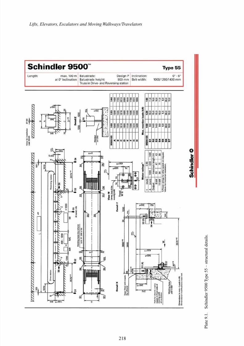
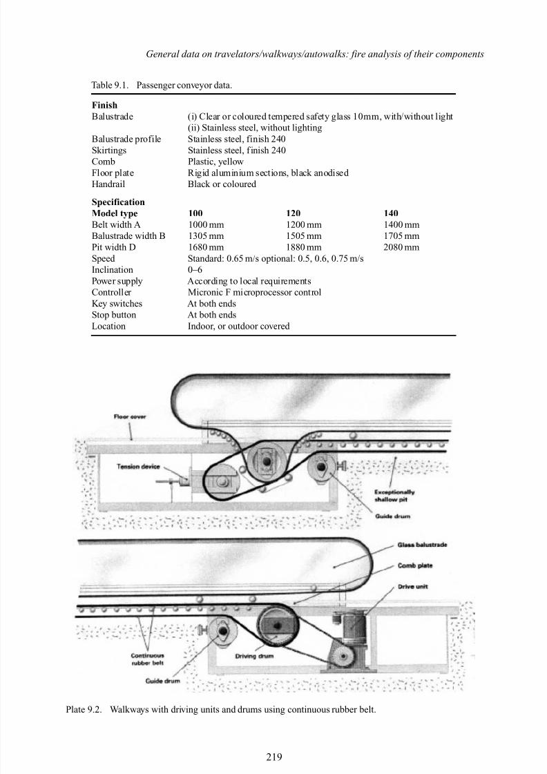
Plate 9.1 gives a skeleton picture of schindler 9500 in operation. Below the floor cover tensiondevice is located on one side with guide drum. A continuous rubber belt over the rollers passes over guide drums on both sides. The drive unit is located near the driving drum with the guide drum.On top of the rollers and under the floor of the rubber tread are provided transverse steel cord and longitudinal reinforcement. Skert guard is provided for the human traffic. Miconic F, the brain of Schindler 9500, is equipped with intelligent communication capability and therefore can transmitand receive information and commands over a local network and can be controlled through central building system such as lobby vision servitel telemonitoring. They followthe safety codes includingEN115/ANSI. It has an exceptionally shallow pit of only 315 mm. Table 9.1 gives specificationsfor this type of passenger walkway. Generally it reaches 100 m length in various units.
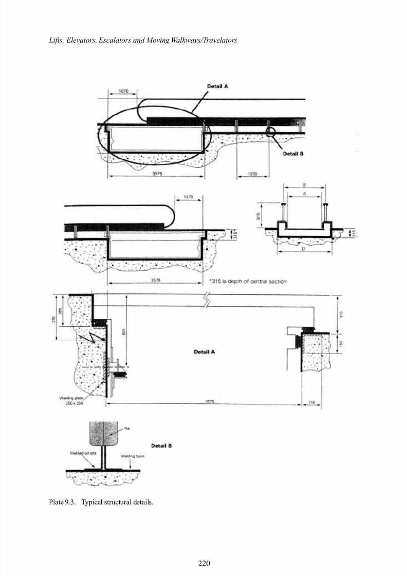
Typical walkways with driving units and drums together with structural details are shown inPlates 9.2 and 9.3 respectively.
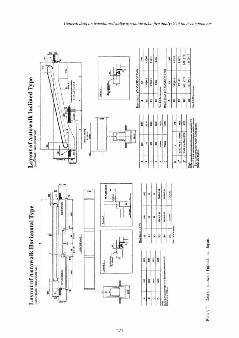
9.3 FUJITEC GS 8000 SERIES AUTOWALK
The basic specifications are given in Table 9.1 serves passenger with its exceptional smoothness.The basic specification are for models 1000 and1200 series. They can be horizontal (0) and inclined types for 10 and 12 angles. The entire design and its specifications are based on EN 115. Plate 9.4indicates various dimensions of the Autowalks and they are reproduced with the permission of Fujitec London office.
Standard safety devices, which are:
1. H and rail safety guard.2. Emergency stop button.
217
8/10/2019 Lifts Elevators Escalators and Moving Walkways Travelators 2DE2
http://slidepdf.com/reader/full/lifts-elevators-escalators-and-moving-walkways-travelators-2de2 29/169
Lifts, Elevators, Escalators and Moving Walkways/Travelators
P l a t e 9 . 1 . S c h i n d l e r 9 5 0 0 T y p e 5 5 – s t r u c t u r a l d e t a i l s .
218
8/10/2019 Lifts Elevators Escalators and Moving Walkways Travelators 2DE2
http://slidepdf.com/reader/full/lifts-elevators-escalators-and-moving-walkways-travelators-2de2 30/169
General data on travelators/walkways/autowalks: fire analysis of their components
Table 9.1. Passenger conveyor data.
FinishBalustrade (i) Clear or coloured tempered safety glass 10mm, with/without light
(ii) Stainless steel, without lightingBalustrade profile Stainless steel, finish 240Skirtings Stainless steel, f inish 240Comb Plastic, yellowFloor plate Rigid aluminium sections, black anodised Handrail Black or coloured
SpecificationModel type 100 120 140Belt width A 1000 mm 1200 mm 1400 mmBalustrade width B 1305 mm 1505 mm 1705 mmPit width D 1680 mm 1880 mm 2080 mmSpeed Standard: 0.65 m/s optional: 0.5, 0.6, 0.75 m/s
Inclination 0–6Power supply According to local requirementsController Micronic F microprocessor controlKey switches At both endsStop button At both endsLocation Indoor, or outdoor covered
Plate 9.2. Walkways with driving units and drums using continuous rubber belt.
219
8/10/2019 Lifts Elevators Escalators and Moving Walkways Travelators 2DE2
http://slidepdf.com/reader/full/lifts-elevators-escalators-and-moving-walkways-travelators-2de2 31/169
Lifts, Elevators, Escalators and Moving Walkways/Travelators
Plate 9.3. Typical structural details.
220
8/10/2019 Lifts Elevators Escalators and Moving Walkways Travelators 2DE2
http://slidepdf.com/reader/full/lifts-elevators-escalators-and-moving-walkways-travelators-2de2 32/169
General data on travelators/walkways/autowalks: fire analysis of their components
P l a t e 9 . 4 . D a t a o n a u t o w a l k F u j i t e c h i n c .
, J a p a n .
221
8/10/2019 Lifts Elevators Escalators and Moving Walkways Travelators 2DE2
http://slidepdf.com/reader/full/lifts-elevators-escalators-and-moving-walkways-travelators-2de2 33/169
Lifts, Elevators, Escalators and Moving Walkways/Travelators
3. Skirt guard obstruction safety device.4. Broken drive chain safety device.5. Broken step (pallet) chain safety device.6. Brake.7. Demarcation line.8. Reversal protection device.9. Governor.
10. Comb safety device.11. Step (pallet) sag safety device.12. Auxiliary braise.13. Phase failure (phase reversal) protection.14. Step upthrust safety device.
The optional safety devices are mentioned which are:
15. Skirt guards.16. Fire shutter inter located device.17. Broken hand rail safety device.18. Hand rail safety delay sensing device.19. Tandem operation interlock.20. Dress guard.
9.4 FIRE AND ESCALATORS/TRAVELATORS
9.4.1 Introduction
A reference is made to bibliography (1-250) relevant to this section related to fire. Fire is the primary cause of loss of life and property throughout the world. During the past two decades fire hasdamaged hundreds of thousands of structures. Significant advances have been made in controllingor mitigating the effects of fire. Various methods have been developed to protect buildings. Newmaterials have been developed or invented. A considerable time is spent by various researchers onthe development of mathematical models to simulate the behaviour of structural members in fire.This is possible only if one uses numerical and computer techniques. A large number of computer programs that calculate the fire resistance of structural members now exist. The input data for thesecomputer programs require, apart from loading and fire density, thermal and mechanical propertiesof variousmaterials at elevated temperatures. In addition, the expected severity of building fires and
temperature time relation have also been developed. Most of these properties have been codified.The closet measures related to building design are probably those for the confinement of a fire.These measures include fire barriers capable of delaying or preventing spread of fire, dimensionsand locations of buildings. All these measures are directly related to the detailed knowledge of themechanics and severity of fire. It is, therefore, essential to outline some areas outside the domainof a structural engineer which he or she should be aware of. Some of these are described below:
a) Mechanics of fluids and building aerodynamics applicable to fire engineering. b) Conduction of heat in solids.c) Convection and radiation heat transfer.d) Thermochemistry.e) Chemical equilibrium and thermal decomposition.f) Fire dynamics.
i) Flame height and fire plumes.ii) Air entrainment into buoyant jet flames.
iii) Ceiling jet flows, vent flows and natural convention wall flows.iv) Combustion conditions, and smouldering combustion.
222
8/10/2019 Lifts Elevators Escalators and Moving Walkways Travelators 2DE2
http://slidepdf.com/reader/full/lifts-elevators-escalators-and-moving-walkways-travelators-2de2 34/169
General data on travelators/walkways/autowalks: fire analysis of their components
v) Flammability limits and flaming ignition of solids.vi) Smoke production, smoke and heat venting.
g) Burning rates and calorimetry.h) Compartment fire modelling and fire models for enclosures.i) Stochastic models for fire growth. j) Explosion protection.k) Detection systems, automatic sprinkler systems.l) Foam system and foam agents.
Within the non-structural analysis, structural analysts must be aware of hazard calculations, risk analysis and probability methods.
The main concern of the structural engineer is the properties of the various materials involved and the analytical tools available for the design of structural elements in fire. They are given later on in this text under various sections.
No matter how many precautions are taken to improvethe fire safety design of buildings, they will
not be complete without sufficient availability of training in professional education and practice.The main objective is to prepare sufficient manuals of awareness and to transfer knowledge of firesafety of buildings to the building design practitioners by way of courses and seminars at variousinstitutions. Architects and engineers must place importance on fire safety provisions and allowfunds for training facilities.
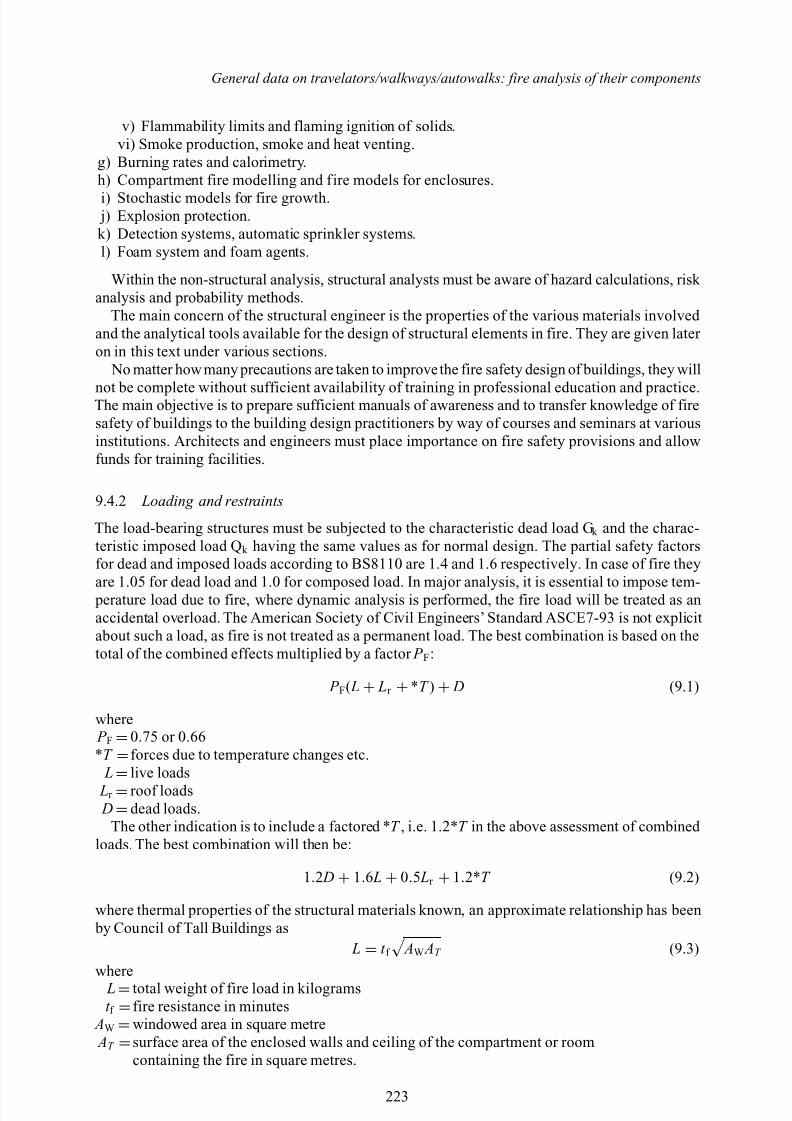
9.4.2 Loading and restraints
The load-bearing structures must be subjected to the characteristic dead load G k and the charac-teristic imposed load Q k having the same values as for normal design. The partial safety factorsfor dead and imposed loads according to BS8110 are 1.4 and 1.6 respectively. In case of fire they
are 1.05 for dead load and 1.0 for composed load. In major analysis, it is essential to impose tem- perature load due to fire, where dynamic analysis is performed, the fire load will be treated as anaccidental overload. The American Society of Civil Engineers’ Standard ASCE7-93 is not explicitabout such a load, as fire is not treated as a permanent load. The best combination is based on thetotal of the combined effects multiplied by a factor P F :
P F( L + Lr + *T ) + D (9.1)
where P F =0.75 or 0.66*T =forces due to temperature changes etc. L
=live loads
Lr =roof loads D =dead loads.
The other indication is to include a factored * T , i.e. 1.2* T in the above assessment of combined loads. The best combination will then be:
1.2 D + 1.6 L + 0.5 Lr + 1.2*T (9.2)
where thermal properties of the structural materials known, an approximate relationship has been by Council of Tall Buildings as
L = t f
AW AT (9.3)
where L=total weight of fire load in kilogramst f =fire resistance in minutes
AW =windowed area in square metre AT =surface area of the enclosed walls and ceiling of the compartment or room
containing the fire in square metres.
223
8/10/2019 Lifts Elevators Escalators and Moving Walkways Travelators 2DE2
http://slidepdf.com/reader/full/lifts-elevators-escalators-and-moving-walkways-travelators-2de2 35/169
Lifts, Elevators, Escalators and Moving Walkways/Travelators
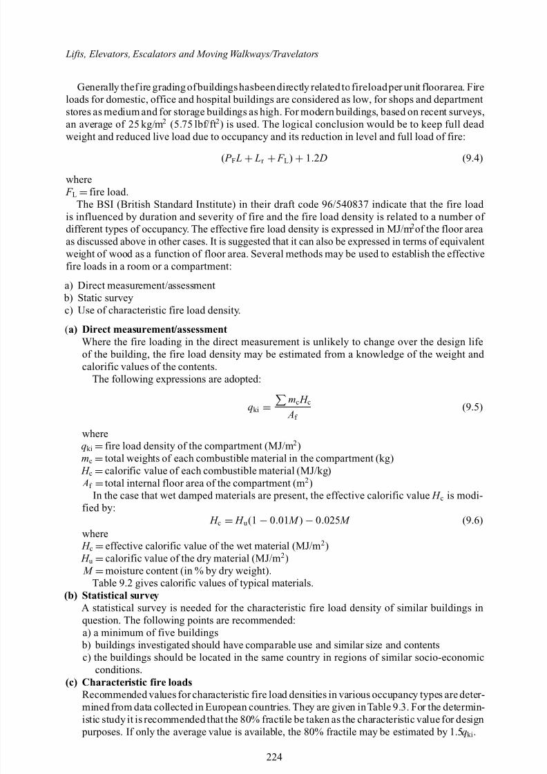
Generally thef ire grading ofbuildingshasbeendirectly related to fireloadper unit floorarea. Fireloads for domestic, office and hospital buildings are considered as low, for shops and departmentstores as medium and for storage buildings as high. For modern buildings, based on recent surveys,an average of 25 kg/m 2 (5.75 lbf/ft 2) is used. The logical conclusion would be to keep full dead weight and reduced live load due to occupancy and its reduction in level and full load of fire:
( P F L + Lr + F L) + 1.2 D (9.4)
where F L =fire load.
The BSI (British Standard Institute) in their draft code 96/540837 indicate that the fire load is influenced by duration and severity of fire and the fire load density is related to a number of different types of occupancy. The effective fire load density is expressed in MJ/m 2of the floor areaas discussed above in other cases. It is suggested that it can also be expressed in terms of equivalentweight of wood as a function of floor area. Several methods may be used to establish the effective
fire loads in a room or a compartment:a) Direct measurement/assessment
b) Static surveyc) Use of characteristic fire load density.
(a) Direct measurement/assessmentWhere the fire loading in the direct measurement is unlikely to change over the design lifeof the building, the fire load density may be estimated from a knowledge of the weight and calorific values of the contents.
The following expressions are adopted:
qki =mc H c Af
(9.5)
whereqki =fire load density of the compartment (MJ/m 2)mc =total weights of each combustible material in the compartment (kg) H c =calorific value of each combustible material (MJ/kg) Af =total internal floor area of the compartment (m 2)
In the case that wet damped materials are present, the effective calorific value H c is modi-fied by:
H c = H u (1 − 0.01 M ) − 0.025 M (9.6)where H c =effective calorific value of the wet material (MJ/m 2) H u =calorific value of the dry material (MJ/m 2) M =moisture content (in % by dry weight).
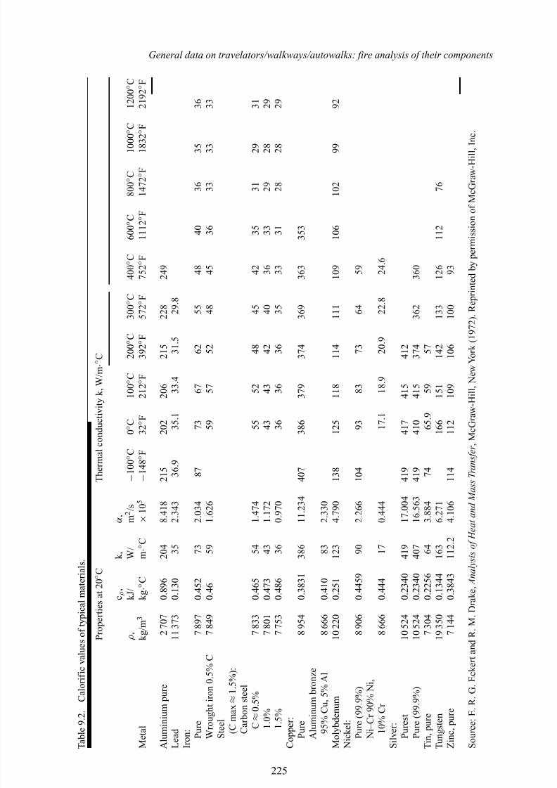
Table 9.2 gives calorific values of typical materials.(b) Statistical survey
A statistical survey is needed for the characteristic fire load density of similar buildings inquestion. The following points are recommended:a) a minimum of five buildings
b) buildings investigated should have comparable use and similar size and contentsc) the buildings should be located in the same country in regions of similar socio-economic
conditions.(c) Characteristic fire loads
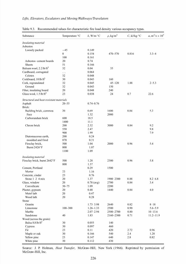
Recommended values for characteristic fire load densities in various occupancy types are deter-mined from data collected in European countries. They are given inTable 9.3. For the determin-istic study it is recommended that the 80% fractile be taken as the characteristic value for design purposes. If only the average value is available, the 80% fractile may be estimated by 1.5 qki .
224
8/10/2019 Lifts Elevators Escalators and Moving Walkways Travelators 2DE2
http://slidepdf.com/reader/full/lifts-elevators-escalators-and-moving-walkways-travelators-2de2 36/169
General data on travelators/walkways/autowalks: fire analysis of their components
T a b l e 9 . 2 . C a l o r i f i c v a l u e s o f t y p i c a l m a t e r i a l s .
P r o p e r t i e s a t 2 0 ◦ C
T h e r m a l c o n d u c t i v i t y k , W / m
· ◦ C
c ρ ,
k ,
α ,
ρ ,
k J /
W /
m 2 / s
− 1 0 0 ◦ C
0 ◦ C
1 0 0 ◦ C
2 0 0 ◦ C
3 0 0 ◦ C 4 0 0 ◦ C
6 0 0 ◦ C
8 0 0 ◦ C
1 0 0 0 ◦ C
1 2 0 0 ◦ C
M e t a l
k g / m 3
k g · ◦ C
m · ◦
C
× 1 0 5
− 1 4 8 ◦ F
3 2 ◦ F
2 1 2 ◦ F
3 9 2 ◦ F
5 7 2 ◦ F 7 5 2 ◦ F
1 1 1 2 ◦ F
1 4 7 2 ◦ F
1 8 3 2 ◦ F
2 1 9 2 ◦ F
A l u m i n i u m p u r e
2 7 0 7
0 . 8 9 6
2 0 4
8 . 4 1 8
2 1 5
2 0 2
2 0 6
2 1 5
2 2 8
2 4 9
L e a d
1 1 3 7 3
0 . 1 3 0
3 5
2 . 3 4 3
3 6 . 9
3 5 . 1
3 3 . 4
3 1 . 5
2 9 . 8
I r o n : P u r e
7 8 9 7
0 . 4 5 2
7 3
2 . 0 3 4
8 7
7 3
6 7
6 2
5 5
4 8
4 0
3 6
3 5
3 6
W r o u g h t i r o n 0 . 5 % C
7 8 4 9
0 . 4 6
5 9
1 . 6 2 6
5 9
5 7
5 2
4 8
4 5
3 6
3 3
3 3
3 3
S t e e l ( C m a x ≈ 1 . 5 %
) :
C a r b o n s t e e l
C ≈ 0 . 5 %
7 8 3 3
0 . 4 6 5
5 4
1 . 4 7 4
5 5
5 2
4 8
4 5
4 2
3 5
3 1
2 9
3 1
1 . 0 %
7 8 0 1
0 . 4 7 3
4 3
1 . 1 7 2
4 3
4 3
4 2
4 0
3 6
3 3
2 9
2 8
2 9
1 . 5 %
7 7 5 3
0 . 4 8 6
3 6
0 . 9 7 0
3 6
3 6
3 6
3 5
3 3
3 1
2 8
2 8
2 9
C o p p e r :
P u r e
8 9 5 4
0 . 3 8 3 1
3 8 6
1 1 . 2 3 4
4 0 7
3 8 6
3 7 9
3 7 4
3 6 9
3 6 3
3 5 3
A l u m i n u m b r o n z e
9 5 % C u , 5 %
A l
8 6 6 6
0 . 4 1 0
8 3
2 . 3 3 0
M o l y b d e n u m
1 0 2 2 0
0 . 2 5 1
1 2 3
4 . 7 9 0
1 3 8
1 2 5
1 1 8
1 1 4
1 1 1
1 0 9
1 0 6
1 0 2
9 9
9 2
N i c k e l :
P u r e ( 9 9 . 9 % )
8 9 0 6
0 . 4 4 5 9
9 0
2 . 2 6 6
1 0 4
9 3
8 3
7 3
6 4
5 9
N i – C r 9 0 % N i ,
1 0 % C r
8 6 6 6
0 . 4 4 4
1 7
0 . 4 4 4
1 7 . 1
1 8 . 9
2 0 . 9
2 2 . 8
2 4 . 6
S i l v e r : P u r e s t
1 0 5 2 4
0 . 2 3 4 0
4 1 9
1 7 . 0 0 4
4 1 9
4 1 7
4 1 5
4 1 2
P u r e ( 9 9 . 9 % )
1 0 5 2 4
0 . 2 3 4 0
4 0 7
1 6 . 5 6 3
4 1 9
4 1 0
4 1 5
3 7 4
3 6 2
3 6 0
T i n , p u r e
7 3 0 4
0 . 2 2 5 6
6 4
3 . 8 8 4
7 4
6 5 . 9
5 9
5 7
T u n g s t e n
1 9 3 5 0
0 . 1 3 4 4
1 6 3
6 . 2 7 1
1 6 6
1 5 1
1 4 2
1 3 3
1 2 6
1 1 2
7 6
Z i n c , p u r e
7 1 4 4
0 . 3 8 4 3
1 1 2 . 2
4 . 1 0 6
1 1 4
1 1 2
1 0 9
1 0 6
1 0 0
9 3
S o u r c e : E . R . G . E c k e r t a n d
R . M . D
r a k e , A n a l y s i s o f H e a t a n d M a s s T r a n s f e r ,
M c G r a w
- H i l l , N e w Y o r k ( 1 9 7 2 ) . R e p r i n t e d b y p e r m i s s i o n o f M c G r a w - H
i l l , I n c .
225
8/10/2019 Lifts Elevators Escalators and Moving Walkways Travelators 2DE2
http://slidepdf.com/reader/full/lifts-elevators-escalators-and-moving-walkways-travelators-2de2 37/169
Lifts, Elevators, Escalators and Moving Walkways/Travelators
Table 9.3. Recommended values for characteristic fire load density various occupancy types.
Substance Temperature ◦C k , W/m ·◦C ρ , kg/m 3 C , kJ/kg ·◦C α, m 2 /s ×107
Insulating material
AsbestosLoosely packed −45 0.149
0 0.154 470–570 0.816 3.3–4100 0.161
Asbestos–cement boards 20 0.74Sheets 51 0.166
Balsam wool, 2.2 lb/ft 3 32 0.04 35Cardboard, corrugated . . . 0.064
Celotex 32 0.048Corkboard, 10 lb/ft 3 30 0.043 160Cork, regranulated 32 0.045 45–120 1.88 2–5.3
Ground 32 0.043 150Fiber, insulating board 20 0.048 240Glass wool, 1.5 lb/ft 3 23 0.038 24 0.7 22.6
Structural and heat-resistant materialsAsphalt 20–55 0.74–0.76Brick:
Building brick, common 20 0.69 1600 0.84 5.2Face 1.32 2000
Carborundum brick 600 18.51400 11.1
Chrom brick 200 2.32 3000 0.84 9.2550 2.47 9.8900 1.99 7.9
Diatomaceous earth, 200 0.24moulded and fired 870 0.31
Fireclay brick, 500 1.04 2000 0.96 5.4Burnt 2426 ◦F 800 1.07
1100 1.09
Insulating material Fireclay brick, burnt 2642 ◦F 500 1.28 2300 0.96 5.8
800 1.37Cement, Portland 0.29 1500
Mortar 23 1.16Concrete, cinder 23 0.76
Stone 1–2–4 mix 20 1.37 1900–2300 0.88 8.2–6.8Glass, window 20 0.78 (avg) 2700 0.84 3.4
Corosilicate 30–75 1.09 2200Plaster, gypsum 20 0.48 1440 0.84 4.0
Metal lath 20 0.47Wood lath 20 0.28
StoneGranite 1.73–3.98 2640 0.82 8–18Limestone 100–300 1.26–1.33 2500 0.90 5.6–5.9Marble 2.07–2.94 2500–2700 0.80 10–13.6Sandstone 40 1.83 2160–2300 0.71 11.2–11.9
Wood (across the grain):Balsa 8.8 lb/ft 3 30 0.055 140Cypress 30 0.097 460
Fir 23 0.11 420 2.72 0.96Maple or oak 30 0.166 540 2.4 1.28Yellow pine 23 0.147 640 2.8 0.82White pine 30 0.112 430
Source: J. P. Holman, Heat Transfer , McGraw-Hill, New York (1966). Reprinted by permission of McGraw-Hill, Inc.
226
8/10/2019 Lifts Elevators Escalators and Moving Walkways Travelators 2DE2
http://slidepdf.com/reader/full/lifts-elevators-escalators-and-moving-walkways-travelators-2de2 38/169
General data on travelators/walkways/autowalks: fire analysis of their components
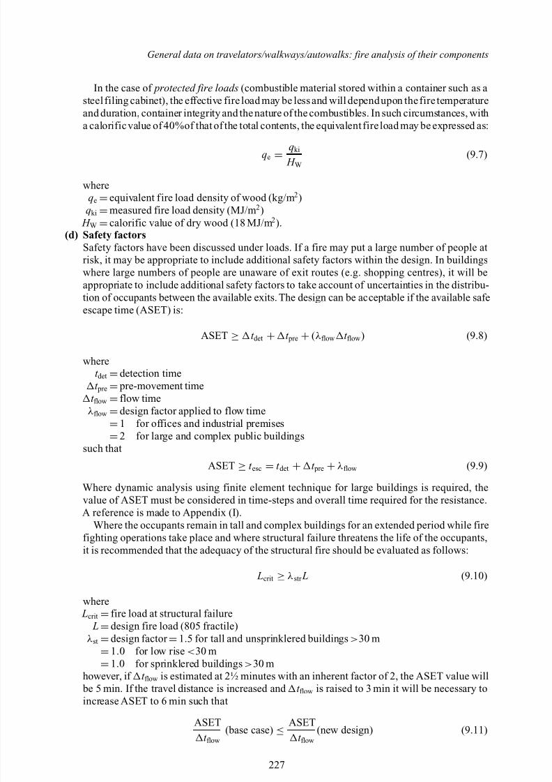
In the case of protected fire loads (combustible material stored within a container such as asteel filing cabinet), the effective fire load may be less and will dependupon thefire temperatureand duration, container integrity and thenature of the combustibles. In such circumstances, witha calorificvalue of 40%of that of the total contents, the equivalent fire load may be expressed as:
qe = qki
H W(9.7)
whereqe =equivalent fire load density of wood (kg/m 2)qki =measured fire load density (MJ/m 2)
H W =calorific value of dry wood (18 MJ/m 2).(d) Safety factors
Safety factors have been discussed under loads. If a fire may put a large number of people atrisk, it may be appropriate to include additional safety factors within the design. In buildings
where large numbers of people are unaware of exit routes (e.g. shopping centres), it will beappropriate to include additional safety factors to take account of uncertainties in the distribu-tion of occupants between the available exits. The design can be acceptable if the available safeescape time (ASET) is:
ASET ≥ t det + t pre + (λ flow t flow ) (9.8)
wheret det =detection timet pre = pre-movement time
t flow
=flow time
λ flow =design factor applied to flow time=1 for offices and industrial premises
=2 for large and complex public buildingssuch that
ASET ≥ t esc = t det + t pre + λ flow (9.9)
Where dynamic analysis using finite element technique for large buildings is required, thevalue of ASET must be considered in time-steps and overall time required for the resistance.A reference is made to Appendix (I).
Where the occupants remain in tall and complex buildings for an extended period while firefighting operations take place and where structural failure threatens the life of the occupants,it is recommended that the adequacy of the structural fire should be evaluated as follows:
Lcrit ≥ λ str L (9.10)
where Lcrit =fire load at structural failure
L=design fire load (805 fractile)λ st =design factor =1.5 for tall and unsprinklered buildings > 30 m
=1.0 for low rise < 30 m
=1.0 for sprinklered buildings > 30 mhowever, if t flow is estimated at 2½ minutes with an inherent factor of 2, the ASET value will be 5 min. If the travel distance is increased and t flow is raised to 3 min it will be necessary toincrease ASET to 6 min such that
ASETt flow
(base case) ≤ ASET
t flow(new design) (9.11)
227
8/10/2019 Lifts Elevators Escalators and Moving Walkways Travelators 2DE2
http://slidepdf.com/reader/full/lifts-elevators-escalators-and-moving-walkways-travelators-2de2 39/169
8/10/2019 Lifts Elevators Escalators and Moving Walkways Travelators 2DE2
http://slidepdf.com/reader/full/lifts-elevators-escalators-and-moving-walkways-travelators-2de2 40/169
General data on travelators/walkways/autowalks: fire analysis of their components
where A f =floor area (m 2)mv =the total weight (kg) H v
=effective heat value (Mcal/m 2) for each individual material v
qc is also given in terms of an equivalent amount of wood per unit area Af .A modified formula exists for qc :
qc = 1 At
mv H v (9.17)
in which At is the total area of the surfaces bounding the compartment (m 2).The connection between the different fire load definitions is given by:
qc = At
A f q (Mcal / m2) and qc =
At
4.5 A f q (kg / m 2) (9.18)
A further development, leads to a more differentiated characterization of the fire load. The valueof q is:
q = 1 At
µ vmv H v (9.19)
in which µ v denotes a dimensionless coefficient between 0 and 1, given the real degree of com- bustible for each individual component v of the fire load.The coefficient µ v depends on thedurationof the fire and the temperature-time characteristics of the fire compartment.
The range of fire densityIt is concluded that for q the temperature–time relation is very important.
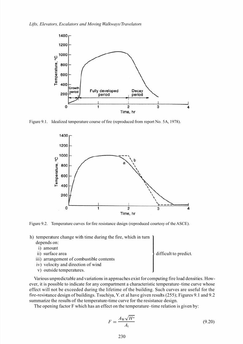
9.4.3 Temperature–time relation
A great deal of research, involving theory, experiment and data monitoring on site (41-250), has been carried out and is still continuing with regard to the time–temperature relation. In this sectiona few examples are given to show different practices.
In general it is widely believed that the temperature course of fire may be divided into thefollowing three periods:
a) the growth period b) the fully developed period c) the capacity period.
To determine the temperature course, it is necessary to know at each moment during a fire rateat which heat is produced and the rate which heat is lost to exposed materials and surroundings.Several of the parameters that determine heat production and heat losses can be categorized asfollows:
a) material properties b) room dimensionsc) emissivity of flamesd) exposed materials
predicted with reasonable accuracy
e) gases that burn outside the roomf) loss of unburnt particles through windowg) temperature difference in the room.
predicted with less reasonable accuracy
229
8/10/2019 Lifts Elevators Escalators and Moving Walkways Travelators 2DE2
http://slidepdf.com/reader/full/lifts-elevators-escalators-and-moving-walkways-travelators-2de2 41/169
Lifts, Elevators, Escalators and Moving Walkways/Travelators
Figure 9.1. Idealized temperature course of fire (reproduced from report No. 5A, 1978).
Figure 9.2. Temperature curves for fire resistance design (reproduced courtesy of the ASCE).
h) temperature change with time during the fire, which in turndepends on:
i) amountii) surface area
iii) arrangement of combustible contentsiv) velocity and direction of wind v) outside temperatures.
difficult to predict.
Various unpredictable and variations in approaches exist for computing fire load densities. How-ever, it is possible to indicate for any compartment a characteristic temperature–time curve whoseeffect will not be exceeded during the lifetime of the building. Such curves are useful for thefire-resistance design of buildings. Tsuchiya, Y. et al have given results (255); Figures 9.1 and 9.2
summarize the results of the temperature-time curve for the resistance design.The opening factor F which has an effect on the temperature–time relation is given by:
F = AW√ H ∗
At(9.20)
230
8/10/2019 Lifts Elevators Escalators and Moving Walkways Travelators 2DE2
http://slidepdf.com/reader/full/lifts-elevators-escalators-and-moving-walkways-travelators-2de2 42/169
General data on travelators/walkways/autowalks: fire analysis of their components
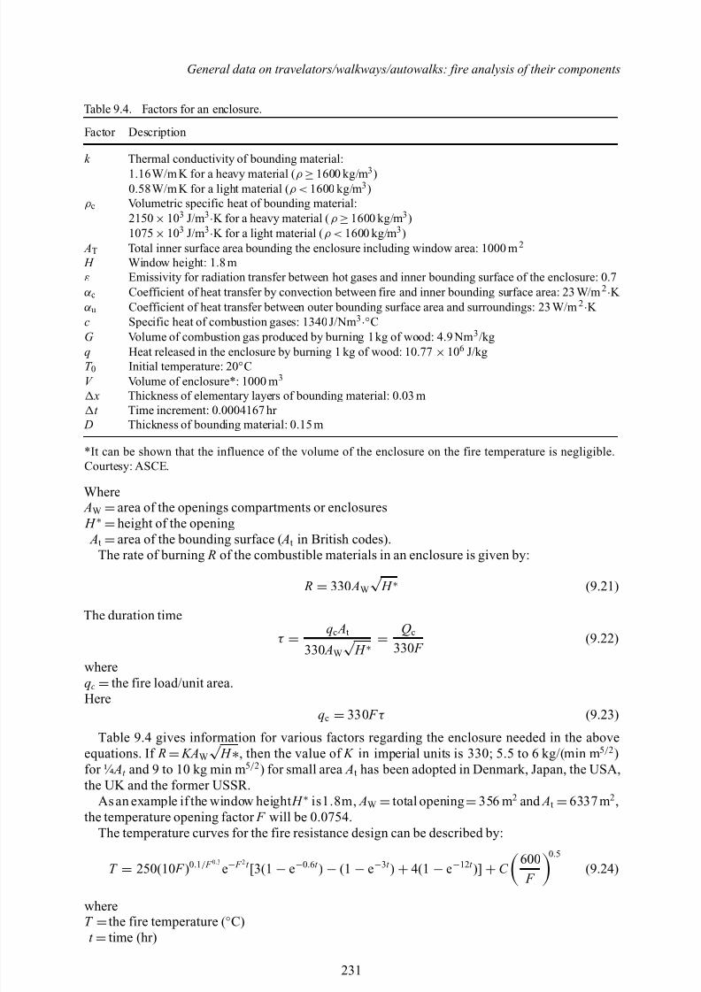
Table 9.4. Factors for an enclosure.
Factor Description
k Thermal conductivity of bounding material:
1.16W/m K for a heavy material ( ρ ≥1600 kg/m 3 )0.58W/m K for a light material ( ρ < 1600 kg/m 3 )
ρ c Volumetric specific heat of bounding material:2150 ×103 J/m 3·K for a heavy material ( ρ ≥1600 kg/m 3 )1075 ×103 J/m 3·K for a light material ( ρ < 1600 kg/m 3 )
AT Total inner surface area bounding the enclosure including window area: 1000 m 2
H Window height: 1.8 mε Emissivity for radiation transfer between hot gases and inner bounding surface of the enclosure: 0.7α c Coefficient of heat transfer by convection between fire and inner bounding surface area: 23 W/m 2·K αu Coefficient of heat transfer between outer bounding surface area and surroundings: 23 W/m 2·K c Specific heat of combustion gases: 1340J/Nm 3·◦CG Volume of combustion gas produced by burning 1kg of wood: 4.9 Nm 3 /kgq Heat released in the enclosure by burning 1 kg of wood: 10.77 ×10⁶ J/kgT 0 Initial temperature: 20 ◦CV Volume of enclosure*: 1000 m 3
x Thickness of elementary layers of bounding material: 0.03 mt Time increment: 0.0004167 hr
D Thickness of bounding material: 0.15 m
*It can be shown that the influence of the volume of the enclosure on the fire temperature is negligible.Courtesy: ASCE.
Where AW
=area of the openings compartments or enclosures
H ∗ =height of the opening At =area of the bounding surface ( At in British codes).
The rate of burning R of the combustible materials in an enclosure is given by:
R = 330 AW√ H ∗ (9.21)
The duration time
τ = qc At
330 AW√ H ∗= Qc
330 F (9.22)
whereqc
=the fire load/unit area.
Hereqc = 330 F τ (9.23)
Table 9.4 gives information for various factors regarding the enclosure needed in the aboveequations. If R= KAW√ H ∗, then the value of K in imperial units is 330; 5.5 to 6 kg/(min m 5/ 2)for ¼ At and 9 to 10 kg min m 5/ 2) for small area At has been adopted in Denmark, Japan, the USA,the UK and the former USSR.
As an example if the window height H ∗ is1.8m, AW =total opening =356 m 2 and At =6337 m 2 ,the temperature opening factor F will be 0.0754.
The temperature curves for the fire resistance design can be described by:
T = 250(10 F )0.1/ F 0.3
e− F 2
t [3(1 − e−0.6t ) − (1 − e−3t ) + 4(1 − e−12t )] + C 600 F
0.5
(9.24)
whereT =the fire temperature ( ◦C)t =time (hr)
231
8/10/2019 Lifts Elevators Escalators and Moving Walkways Travelators 2DE2
http://slidepdf.com/reader/full/lifts-elevators-escalators-and-moving-walkways-travelators-2de2 43/169
Lifts, Elevators, Escalators and Moving Walkways/Travelators
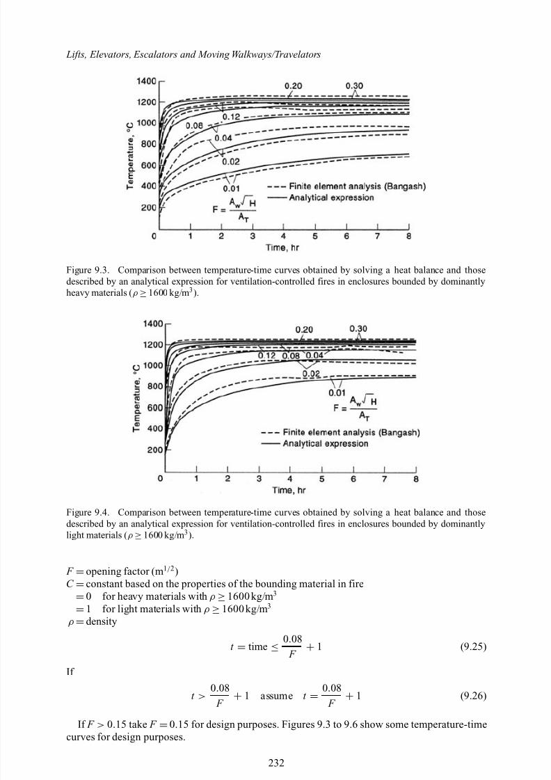
Figure 9.3. Comparison between temperature-time curves obtained by solving a heat balance and thosedescribed by an analytical expression for ventilation-controlled fires in enclosures bounded by dominantlyheavy materials ( ρ ≥1600 kg/m 3 ).
Figure 9.4. Comparison between temperature-time curves obtained by solving a heat balance and thosedescribed by an analytical expression for ventilation-controlled fires in enclosures bounded by dominantlylight materials ( ρ
≥1600 kg/m 3 ).
F =opening factor (m 1/ 2)C =constant based on the properties of the bounding material in fire
=0 for heavy materials with ρ ≥1600 kg/m 3
=1 for light materials with ρ ≥1600 kg/m 3
ρ =density
t = time ≤ 0.08
F + 1 (9.25)
If
t >0.08 F + 1 assume t =
0.08 F + 1 (9.26)
If F > 0.15 take F =0.15 for design purposes. Figures 9.3 to 9.6 show some temperature-timecurves for design purposes.
232
8/10/2019 Lifts Elevators Escalators and Moving Walkways Travelators 2DE2
http://slidepdf.com/reader/full/lifts-elevators-escalators-and-moving-walkways-travelators-2de2 44/169
General data on travelators/walkways/autowalks: fire analysis of their components
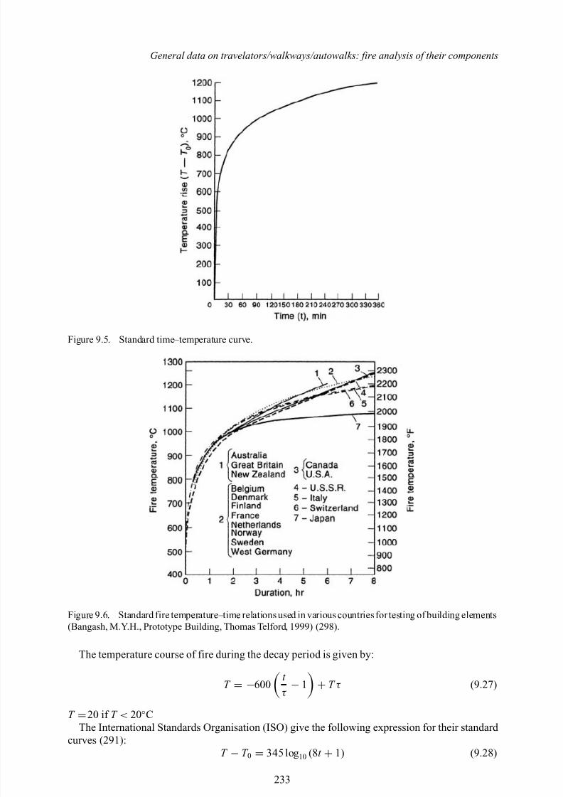
Figure 9.5. Standard time–temperature curve.
Figure 9.6. Standard fire temperature–time relations used in various countries for testing of building elements(Bangash, M.Y.H., Prototype Building, Thomas Telford, 1999) (298).
The temperature course of fire during the decay period is given by:
T
= −600
t τ
− 1
+ T τ (9.27)
T =20 if T < 20◦CThe International Standards Organisation (ISO) give the following expression for their standard
curves (291):T − T 0 = 345 log 10 (8t + 1) (9.28)
233
8/10/2019 Lifts Elevators Escalators and Moving Walkways Travelators 2DE2
http://slidepdf.com/reader/full/lifts-elevators-escalators-and-moving-walkways-travelators-2de2 45/169
Lifts, Elevators, Escalators and Moving Walkways/Travelators
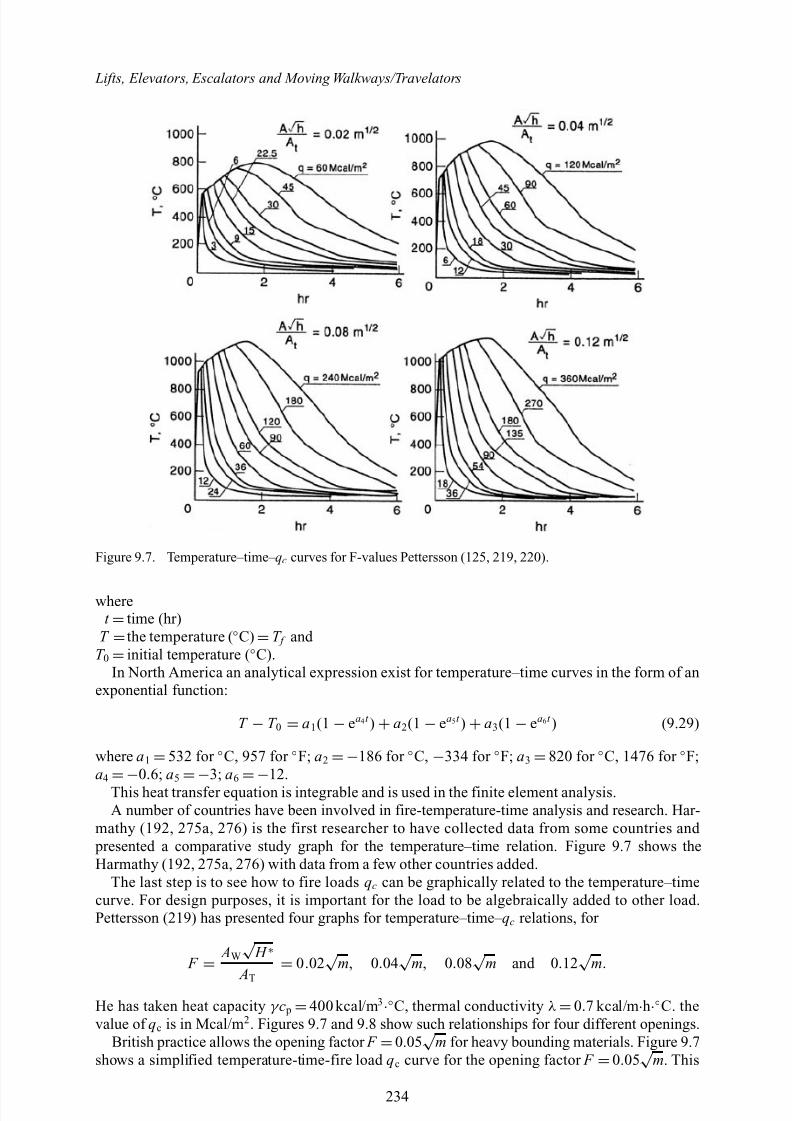
Figure 9.7. Temperature–time– qc curves for F-values Pettersson (125, 219, 220).
wheret =time (hr)
T =the temperature ( ◦C) =T f and T 0 =initial temperature ( ◦C).
In North America an analytical expression exist for temperature–time curves in the form of anexponential function:
T − T 0 = a 1(1 − ea4 t ) + a2(1 − ea 5 t ) + a3(1 − ea 6 t ) (9.29)
where a 1 =532 for ◦C, 957 for ◦F; a2 =−186 for ◦C, −334 for ◦F; a3 =820 for ◦C, 1476 for ◦F;a4
=−0.6; a5
=−3; a6
=−12.
This heat transfer equation is integrable and is used in the finite element analysis.A number of countries have been involved in fire-temperature-time analysis and research. Har-
mathy (192, 275a, 276) is the first researcher to have collected data from some countries and presented a comparative study graph for the temperature–time relation. Figure 9.7 shows theHarmathy (192, 275a, 276) with data from a few other countries added.
The last step is to see how to fire loads qc can be graphically related to the temperature–timecurve. For design purposes, it is important for the load to be algebraically added to other load.Pettersson (219) has presented four graphs for temperature–time– qc relations, for
F
=
AW√ H ∗
AT = 0.02√ m, 0.04√ m, 0.08√ m and 0 .12√ m.
He has taken heat capacity γ c p =400 kcal/m 3·◦C, thermal conductivity λ =0.7 kcal/m ·h·◦C. thevalue of qc is in Mcal/m 2 . Figures 9.7 and 9.8 show such relationships for four different openings.
British practice allows the opening factor F =0.05√ m for heavy bounding materials. Figure 9.7shows a simplified temperature-time-fire load qc curve for the opening factor F =0.05√ m. This
234
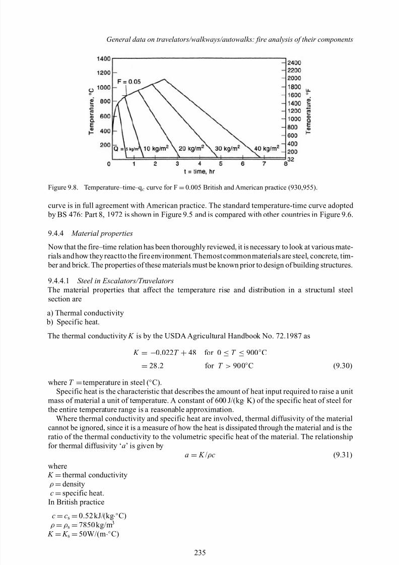
8/10/2019 Lifts Elevators Escalators and Moving Walkways Travelators 2DE2
http://slidepdf.com/reader/full/lifts-elevators-escalators-and-moving-walkways-travelators-2de2 46/169
General data on travelators/walkways/autowalks: fire analysis of their components
Figure 9.8. Temperature–time–q c curve for F =0.005 British and American practice (930,955).
curve is in full agreement with American practice. The standard temperature-time curve adopted by BS 476: Part 8, 1972 is shown in Figure 9.5 and is compared with other countries in Figure 9.6.
9.4.4 Material properties
Now that the fire–time relation has been thoroughly reviewed, it is necessary to look at various mate-rials andhow they reactto the fireenvironment. Themostcommonmaterials are steel, concrete, tim- ber and brick. The properties of these materials must be known prior to design of building structures.
9.4.4.1 Steel in Escalators/TravelatorsThe material properties that affect the temperature rise and distribution in a structural steelsection are
a) Thermal conductivity b) Specific heat.
The thermal conductivity K is by the USDA Agricultural Handbook No. 72.1987 as
K = −0.022 T + 48 for 0 ≤ T ≤ 900 ◦C
= 28 .2 for T > 900◦C (9.30)
where T =temperature in steel ( ◦C).Specific heat is the characteristic that describes the amount of heat input required to raise a unit
mass of material a unit of temperature. A constant of 600 J/(kg · K) of the specific heat of steel for the entire temperature range is a reasonable approximation.
Where thermal conductivity and specific heat are involved, thermal diffusivity of the materialcannot be ignored, since it is a measure of how the heat is dissipated through the material and is theratio of the thermal conductivity to the volumetric specific heat of the material. The relationshipfor thermal diffusivity ‘ a’ is given by
a = K /ρ c (9.31)where K =thermal conductivityρ =density
c =specific heat.In British practice
c =cs =0.52kJ/(kg ·◦C)ρ =ρ s =7850kg/m 3
K = K s =50W/(m ·◦C)
235
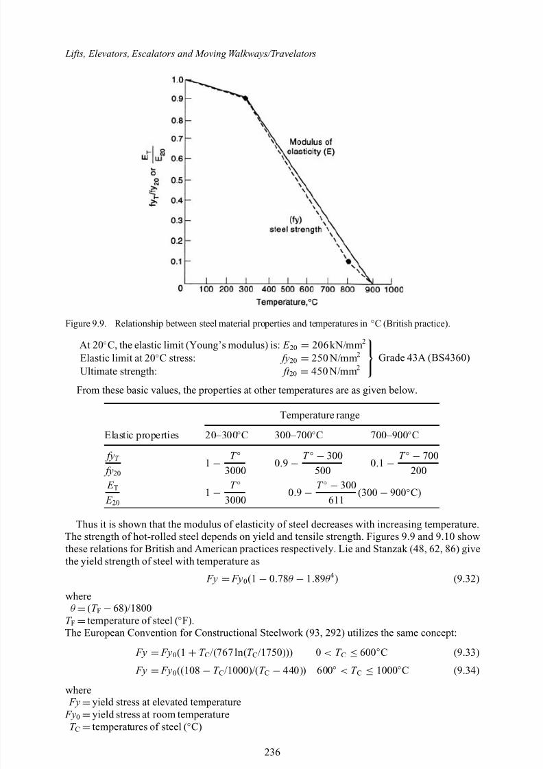
8/10/2019 Lifts Elevators Escalators and Moving Walkways Travelators 2DE2
http://slidepdf.com/reader/full/lifts-elevators-escalators-and-moving-walkways-travelators-2de2 47/169
Lifts, Elevators, Escalators and Moving Walkways/Travelators
Figure 9.9. Relationship between steel material properties and temperatures in ◦C (British practice).
At 20 ◦C, the elastic limit (Young’s modulus) is: E 20 = 206kN/mm 2
Elastic limit at 20 ◦C stress: fy20 = 250 N/mm 2
Ultimate strength: ft 20 = 450 N/mm 2Grade 43A (BS4360)
From these basic values, the properties at other temperatures are as given below.
Temperature range
Elastic properties 20–300 ◦C 300–700 ◦C 700–900 ◦C
fyT
fy201 −
T ◦3000
0.9 − T ◦ − 300
5000.1 −
T ◦ − 700200
E T E 20
1 − T ◦3000
0.9 − T ◦ − 300
611(300 − 900◦C)
Thus it is shown that the modulus of elasticity of steel decreases with increasing temperature.
The strength of hot-rolled steel depends on yield and tensile strength. Figures 9.9 and 9.10 showthese relations for British and American practices respectively. Lie and Stanzak (48, 62, 86) givethe yield strength of steel with temperature as
Fy = Fy 0(1 − 0.78θ − 1.89θ 4) (9.32)
whereθ =(T F −68)/1800
T F =temperature of steel ( ◦F).The European Convention for Constructional Steelwork (93, 292) utilizes the same concept:
Fy = Fy0(1 + T C /(767 ln( T C /1750))) 0 < T C ≤ 600◦C (9.33)
Fy = Fy0((108 − T C /1000)/( T C − 440)) 600 ◦ < T C ≤ 1000◦C (9.34)where Fy =yield stress at elevated temperature
Fy0 =yield stress at room temperatureT C =temperatures of steel ( ◦C)
236
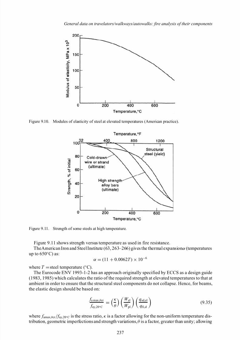
8/10/2019 Lifts Elevators Escalators and Moving Walkways Travelators 2DE2
http://slidepdf.com/reader/full/lifts-elevators-escalators-and-moving-walkways-travelators-2de2 48/169
General data on travelators/walkways/autowalks: fire analysis of their components
Figure 9.10. Modules of elasticity of steel at elevated temperatures (American practice).
Figure 9.11. Strength of some steels at high temperature.
Figure 9.11 shows strength versus temperature as used in fire resistance.TheAmerican Iron and Steel Institute (63, 263–266) gives the thermal expansion α (temperatures
up to 650 ◦C) as:α = (11 + 0.0062 T ) × 10−6
where T =steel temperature ( ◦C).The Eurocode ENV 1993-1-2 has an approach originally specified by ECCS as a design guide
(1983, 1985) which calculates the ratio of the required strength at elevated temperatures to that atambient in order to ensure that the structural steel components do not collapse. Hence, for beams,the elastic design should be based on:
f a max, θ cr
f ay,20 ◦C =κθ
W el
W pl
qsd,el
qfi,d (9.35)
where f amax, θ cr / f ay,20 ◦C is the stress ratio, κ is a factor allowing for the non-uniform temperature dis-tribution, geometric imperfections and strength variations, θ is a factor, greater than unity; allowing
237
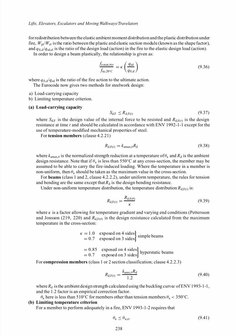
8/10/2019 Lifts Elevators Escalators and Moving Walkways Travelators 2DE2
http://slidepdf.com/reader/full/lifts-elevators-escalators-and-moving-walkways-travelators-2de2 49/169
Lifts, Elevators, Escalators and Moving Walkways/Travelators
for redistribution between the elastic ambient moment distribution and the plastic distribution under fire, W pl/W el is the ratio between the plastic and elastic section module (known as the shape factor),and qfi,d /qsd,el is the ratio of the design load (action) in the fire to the elastic design load (action).
In order to design a beam plastically, the relationship is given as:
f a max, θ cr
f ay,20 ◦C = κ qsd
qfi,d (9.36)
where qfi,d /qsd is the ratio of the fire action to the ultimate action.The Eurocode now gives two methods for steelwork design:
a) Load-carrying capacity b) Limiting temperature criterion.
(a) Load-carrying capacityS d,F
≤ Rd,F( t ) (9.37)
where S d,F is the design value of the internal force to be resisted and Rd,F( t ) is the designresistance at time t and should be calculated in accordance with ENV 1992-1-1 except for theuse of temperature-modified mechanical properties of steel.
For tension members (clause 4.2.21)
Rd,F( t ) = k amax, θ Rd (9.38)
where k amax, θ is the normalized strength reduction at a temperature of θ a and Rd is the ambientdesign resistance. Note that if θ a is less than 550 ◦C at any cross-section, the member may beassumed to be able to carry the fire-induced loading. Where the temperature in a member isnon-uniform, then θ a should be taken as the maximum value in the cross-section.
For beams (class 1 and 2, clause 4.2.2.2), under uniform temperature, the rules for tensionand bending are the same except that Rd is the design bending resistance.
Under non-uniform temperature distribution, the temperature distribution Rd,F( t ) is:
Rd,F( t ) = Rd,F( θ )
κ(9.39)
where κ is a factor allowing for temperature gradient and varying end conditions (Petterssonand Jonsson (219, 220) and Rd,F( θ ) is the design resistance calculated from the maximumtemperature in the cross-section:
κ = 1.0 exposed on 4 sides= 0.7 exposed on 3 sides simple beams
= 0.85 exposed on 4 sides
= 0.7 exposed on 3 sides hyperstatic beams
For compression members (class 1 or 2 section classification; clause 4.2.2.3)
Rd,F( t ) = k amx, θ Rd
1.2(9.40)
where Rd is the ambient designstrength calculated using the buckling curve c of ENV 1993-1-1,and the 1.2 factor is an empirical correction factor.
θ a here is less than 510 ◦C for members other than tension members θ a < 350 ◦C.(b) Limiting temperature criterion
For a member to perform adequately in a fire, ENV 1993-1-2 requires that
θ a ≤ θ a,cr (9.41)
238
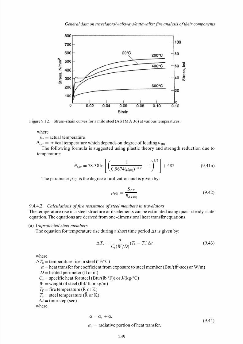
8/10/2019 Lifts Elevators Escalators and Moving Walkways Travelators 2DE2
http://slidepdf.com/reader/full/lifts-elevators-escalators-and-moving-walkways-travelators-2de2 50/169
General data on travelators/walkways/autowalks: fire analysis of their components
Figure 9.12. Stress–strain curves for a mild steel (ASTM A 36) at various temperatures.
whereθ a =actual temperature
θ a,cr =critical temperature which depends on degree of loading µ (0) .The following formula is suggested using plastic theory and strength reduction due to
temperature:
θ a,cr = 78 .38ln 1
0.9674( µ (0) )3.833 − 11/ 2
+ 482 (9.41a)
The parameter µ (0) is the degree of utilization and is given by:
µ (0) = S d . F
Rd . F (0)(9.42)
9.4.4.2 Calculations of fire resistance of steel members in travelatorsThe temperature rise in a steel structure or its elements can be estimated using quasi-steady-stateequation. The equations are derived from one-dimensional heat transfer equations.
(a) Unprotected steel membersThe equation for temperature rise during a short time period t is given by:
T s = αC s(W / D)
(T f − T s) t (9.43)
whereT s =temperature rise in steel ( ◦F/◦C)α =heat transfer for coefficient from exposure to steel member (Btu/(ft 2·sec) or W/m)
D =heated perimeter (ft or m)C s =specific heat for steel (Btu/(lb ·◦F)) or J/(kg ·◦C)W =weight of steel (lbf/ ft or kg/m)T f =fire temperature ( R or K)T s =steel temperature ( R or K)
t =time step (sec)where
α = α r + α c(9.44)
α r = radiative portion of heat transfer.
239
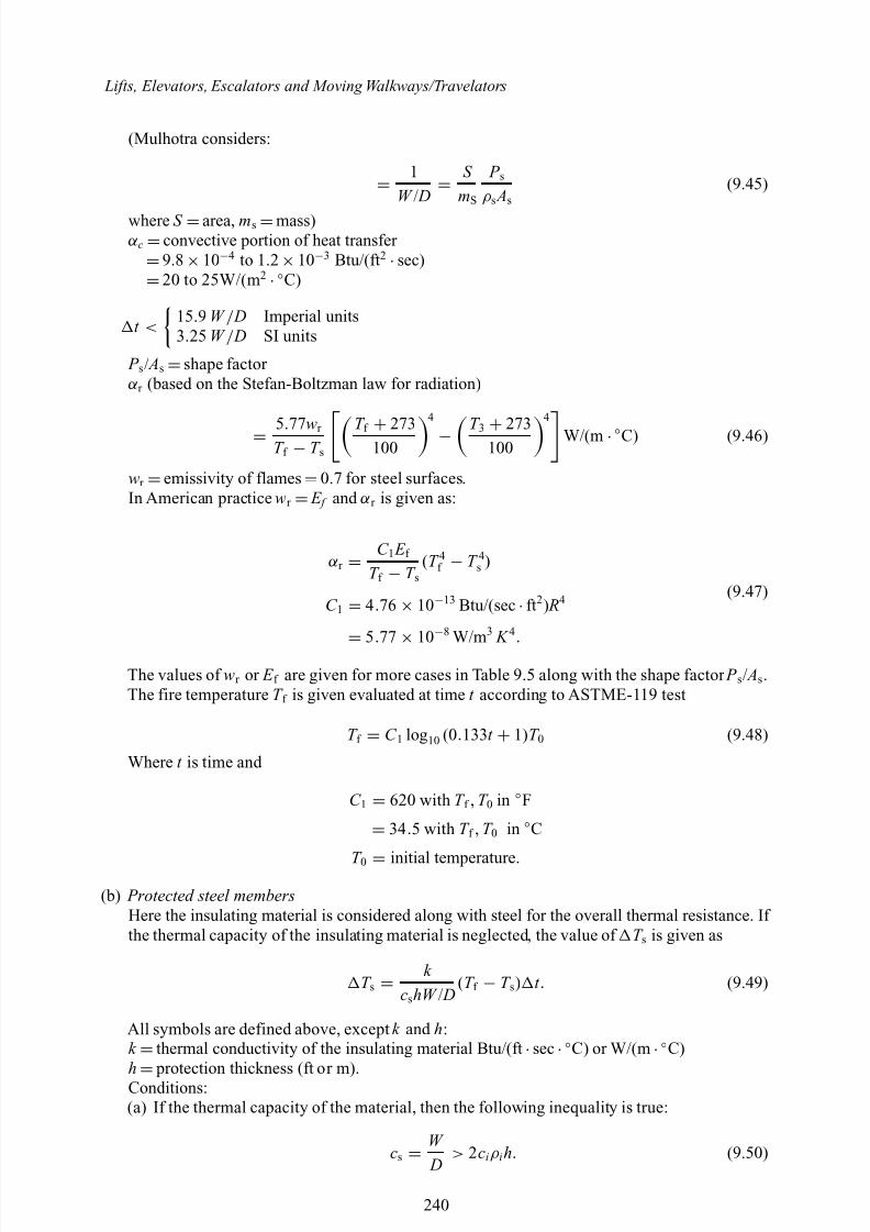
8/10/2019 Lifts Elevators Escalators and Moving Walkways Travelators 2DE2
http://slidepdf.com/reader/full/lifts-elevators-escalators-and-moving-walkways-travelators-2de2 51/169
Lifts, Elevators, Escalators and Moving Walkways/Travelators
(Mulhotra considers:
= 1W / D =
S mS
P sρ s As
(9.45)
where S =area, ms =mass)α c =convective portion of heat transfer
=9.8 ×10⁻⁴ to 1.2 ×10⁻³ Btu/(ft 2 ·sec)
=20 to 25W/(m 2 ·◦C)
t <15 .9 W / D Imperial units3.25 W / D SI units
P s / As =shape factor α r (based on the Stefan-Boltzman law for radiation)
= 5.77wr T f − T s
T f + 273100
4
− T 3 + 273100
4
W/(m ·◦C) (9.46)
wr =emissivity of flames =0.7 for steel surfaces.In American practice wr = E f and α r is given as:
α r = C 1 E f T f − T s
(T 4f − T 4s )
(9.47)C 1 = 4.76 × 10⁻¹³ Btu/(sec ·ft2) R4
= 5.77
× 10−8 W/m 3 K 4 .
The values of wr or E f are given for more cases in Table 9.5 along with the shape factor P s/ As .The fire temperature T f is given evaluated at time t according to ASTME-119 test
T f = C 1 log10 (0.133 t + 1)T 0 (9.48)
Where t is time and
C 1 = 620 with T f , T 0 in ◦F
= 34 .5 with T f , T 0 in ◦C
T 0 = initial temperature.
(b) Protected steel membersHere the insulating material is considered along with steel for the overall thermal resistance. If the thermal capacity of the insulating material is neglected, the value of T s is given as
T s = k
cshW / D(T f − T s) t . (9.49)
All symbols are defined above, except k and h:k =thermal conductivity of the insulating material Btu/(ft ·sec ·◦C) or W/(m ·◦C)h
= protection thickness (ft or m).
Conditions:(a) If the thermal capacity of the material, then the following inequality is true:
cs = W D
> 2ciρ ih. (9.50)
240
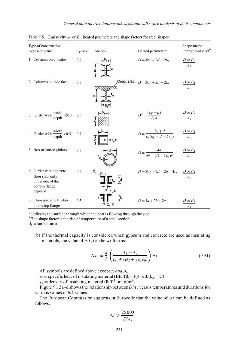
8/10/2019 Lifts Elevators Escalators and Moving Walkways Travelators 2DE2
http://slidepdf.com/reader/full/lifts-elevators-escalators-and-moving-walkways-travelators-2de2 52/169
General data on travelators/walkways/autowalks: fire analysis of their components
Table 9.5. Emissivity ωr or E f , heated perimeters and shape factors for steel shapes.
Type of construction Shape factor exposed to fire ωr or E f Shapes Heated perimeter ∗ unprotected steel †
1. Columns on all sides 0.7 D =4b f +2d −2t w D or P s As
2. Columns outside face 0.3 D =3b f +2d −2t w D or P s As
3. Girder withwidth
depth≮0.5 0.5 D2
= (bf +d )
bf d
D or P s
As
4. Girder withwidthdepth
< 0.5 0.7 D = bf +d
t w (bf + d − 2t w ) D or P s
As
5. Box or lattice girders 0.7 D =
4d d 2 − ( D − 2t w )2
D or P s As
6. Girder with concrete 0.5 D =8b f +2d +2a −4t w D or P s
Asfloor slab, onlyunderside of the bottom flangeexposed
7. Floor girder with slab 0.5 D =4a +2b +2c D or P s Ason the top flange
∗ Indicates the surface through which the heat is flowing through the steel.† The shape factor is the rise of temperature of a steel section. As =surface area.
(b) If the thermal capacity is considered when gypsum and concrete are used as insulatingmaterials, the value of T s can be written as:
T s = k h
T f − T scs(W / D) + 1
2 ciρ iht (9.51)
All symbols are defined above except ci and ρ i .ci =specific heat of insulating material (Btu/(lb ·◦F)) or J/(kg ·◦C)ρ i =density of insulating material (lb/ft 3 or kg/m 3).Figure 9.13a–d shows the relationship between D/ As versus temperatures and durations for
various values of h/k values.The European Commission suggests in Eurocode that the value of t can be defined as
follows:
t ≯25 000 D/ As
241
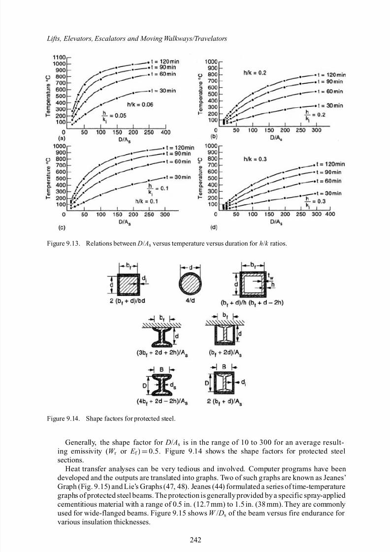
8/10/2019 Lifts Elevators Escalators and Moving Walkways Travelators 2DE2
http://slidepdf.com/reader/full/lifts-elevators-escalators-and-moving-walkways-travelators-2de2 53/169
Lifts, Elevators, Escalators and Moving Walkways/Travelators
Figure 9.13. Relations between D/ As versus temperature versus duration for h/k ratios.
Figure 9.14. Shape factors for protected steel.
Generally, the shape factor for D/ As is in the range of 10 to 300 for an average result-ing emissivity ( W r or E f ) =0.5. Figure 9.14 shows the shape factors for protected steelsections.
Heat transfer analyses can be very tedious and involved. Computer programs have beendeveloped and the outputs are translated into graphs. Two of such graphs are known as Jeanes’Graph (Fig. 9.15) and Lie’s Graphs (47, 48). Jeanes (44) formulated a series of time-temperaturegraphs of protected steel beams. The protection is generally provided by a specific spray-applied cementitious material with a range of 0.5 in. (12.7 mm) to 1.5 in. (38 mm). They are commonlyused for wide-flanged beams. Figure 9.15 shows W / Ds of the beam versus fire endurance for various insulation thicknesses.
242
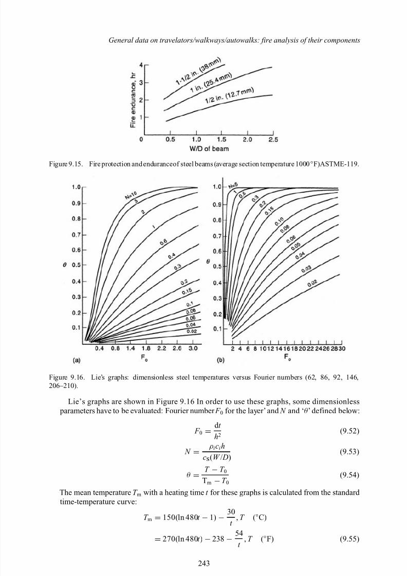
8/10/2019 Lifts Elevators Escalators and Moving Walkways Travelators 2DE2
http://slidepdf.com/reader/full/lifts-elevators-escalators-and-moving-walkways-travelators-2de2 54/169
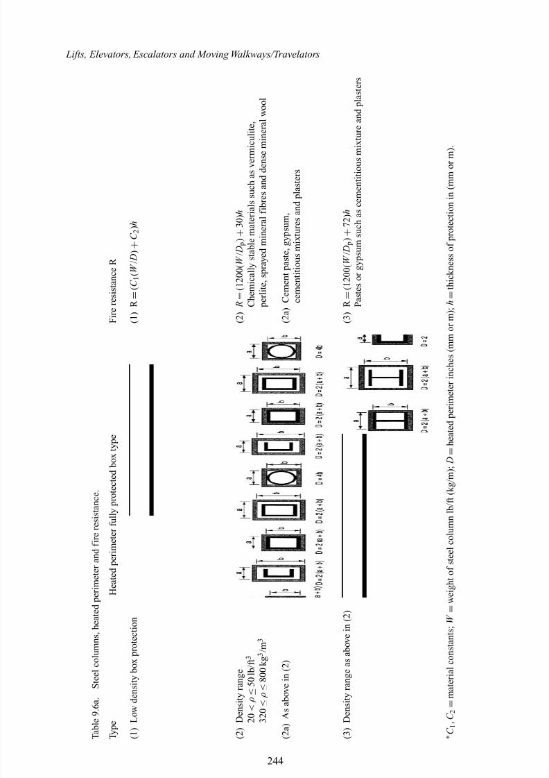
8/10/2019 Lifts Elevators Escalators and Moving Walkways Travelators 2DE2
http://slidepdf.com/reader/full/lifts-elevators-escalators-and-moving-walkways-travelators-2de2 55/169
Lifts, Elevators, Escalators and Moving Walkways/Travelators
T a b l e 9 . 6 a . S t e e l c o l u m n s , h e a t e d p e r i m e t e r a n d f i r e r e s i s t a n c e .
T y p e
H e a t e d p e r i m e t e r f u l l y p r o t e c t e d b o x t y p e
F i r e r e s i s t a n c e R
( 1 ) L o w d e n s i t y b o x p r o t e c t i o n
( 1 ) R
= ( C 1 ( W
/ D ) + C 2 ) h
( 2 ) D e n s i t y r a n g e
( 2 ) R =
( 1 2 0 0 ( W / D
p ) + 3 0 ) h
2 0 < ρ ≤ 5 0 l b / f t 3
C h e m i c a l l y s t a b l e m a t e r i a l s s u c h a s v e r m i c u l i t e ,
3 2 0 ≤ ρ ≤ 8 0 0 k g 3 / m 3
p e r l i t e , s p r a y e d m i n e r a l f i b r e s a n d d e n s e m i n e r a l w o o l
( 2 a ) A s a b o v e i n ( 2 )
( 2 a ) C e m e n t p a s t e , g y p s u m ,
c e m e n t i t i o u s m i x t u r e s a n d p l a s t e r s
( 3 ) D e n s i t y r a n g e a s a b o v e i n ( 2 )
( 3 ) R
= ( 1 2 0 0 ( W / D
p ) + 7 2 ) h
P a s t e s o r g y p s u m s u c h a s c e m e n t i t i o u s m i x t u r e a n d p l a s t e r s
∗ C 1 , C 2
= m a t e r i a l c o n s t a n t s ; W = w e i g h t o f s t e e l c o l u m n l b / f t ( k g / m ) ; D
= h e a t e d p e r i m e t e r i n c h e s ( m m o r m ) ; h
= t h i c k n e s s o f p r o t e c t i o n i n ( m m o r m ) .
244
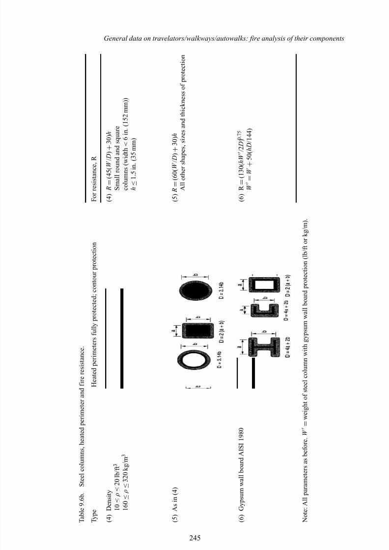
8/10/2019 Lifts Elevators Escalators and Moving Walkways Travelators 2DE2
http://slidepdf.com/reader/full/lifts-elevators-escalators-and-moving-walkways-travelators-2de2 56/169
General data on travelators/walkways/autowalks: fire analysis of their components
T a b l e 9 . 6 b . S t e e l c o l u m n s , h e a t e d p e r i m e t e r a n d f i r e r e s i s t a n c e .
T y p e
H e a t e d p e r i m e t e r s f u l l y p r o t e c t e d ; c o n t o u r p r o t e c t i o n
F o r r e s i s t a n c e , R
( 4 ) D e n s i t y
( 4 ) R =
( 4 5 ( W / D ) + 3 0 ) h
1 0 ≤ ρ ≤ 2 0 l b / f t 3
S m a l l r o u n d a n d s q u a r e
1 6 0 ≤ ρ ≤ 3 2 0 k g / m 3
c o l u m n s ( w i d t h < 6 i n . ( 1 5 2 m m ) )
h ≤ 1 . 5 i n . ( 3 5 m m )
( 5 ) A s i n ( 4 )
( 5 ) R
= ( 6 0 ( W / D ) + 3 0 ) h
A l l o t h e r s h a p e s , s i z e s a n d t h i c k n e s s o f p r o t e c t i o n
( 6 ) G y p s u m w a l l b o a r d A I S I 1 9 8 0
( 6 ) R
= ( 1 3 0 ( h W / 2 D ) 0 . 7 5
W
= W + 5 0 ( h D / 1 4 4 )
N o t e : A l l p a r a m e t e r s a s b e f o r e . W
= w e i g h t o f s t e e l c o l u m n w i t h g y p s u m w a l l b o a r d p r o t e c t i o n ( l b / f t o r k g / m ) .
245
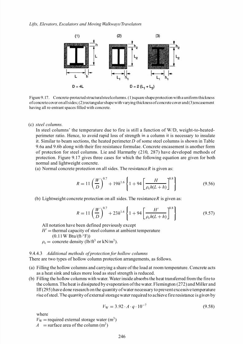
8/10/2019 Lifts Elevators Escalators and Moving Walkways Travelators 2DE2
http://slidepdf.com/reader/full/lifts-elevators-escalators-and-moving-walkways-travelators-2de2 57/169
Lifts, Elevators, Escalators and Moving Walkways/Travelators
Figure 9.17. Concrete-protected structuralsteelcolumns. (1)square shapeprotection with a uniform thicknessof concretecover on all sides; (2) rectangularshape with varying thicknessof concrete cover and(3)encasementhaving all re-entrant spaces filled with concrete.
(c) steel columns.In steel columns’ the temperature due to fire is still a function of W/D, weight-to-heated- perimeter ratio. Hence, to avoid rapid loss of strength in a column it is necessary to insulateit. Similar to beam sections, the heated perimeter D of some steel columns is shown in Table9.6a and 9.6b along with their fire resistance formulae. Concrete encasement is another formof protection for steel columns. Lie and Harmathy (210, 287) have developed methods of protection. Figure 9.17 gives three cases for which the following equation are given for bothnormal and lightweight concrete.(a) Normal concrete protection on all sides. The resistance R is given as:
R = 11 W D
0.7
+ 19h1.6 1 + 94 H ρ ch( L + h)
0.8
(9.56)
(b) Lightweight concrete protection on all sides. The resistance R is given as:
R = 11W D
0.7
+ 23h1.6 1 + 94 H
ρ ch( L + h)
0.8
(9.57)
All notation have been defined previously except H =thermal capacity of steel column at ambient temperature
(0.11W Btu/(ft
·◦F))
ρ c = concrete density (lb/ft 3 or kN/m 3).
9.4.4.3 Additional methods of protection for hollow columnsThere are two types of hollow column protection arrangements, as follows.
(a) Filling the hollow columns and carrying a share of the load at room temperature. Concrete actsas a heat sink and takes more load as steel strength is reduced.
(b) Filling the hollow columns with water. Water inside absorbs the heat transferred from the fire tothe column. The heat is dissipated by evaporation of the water. Flemington (272) and Miller and Iff (295)have done research on the quantity of water necessary to prevent excessive temperaturerise of steel. The quantity of external storagewater required to achieve fire resistance is given by
V W = 3.92 · A·q ·10−7 (9.58)
whereV W =required external storage water (m 3) A =surface area of the column (m 2)
246
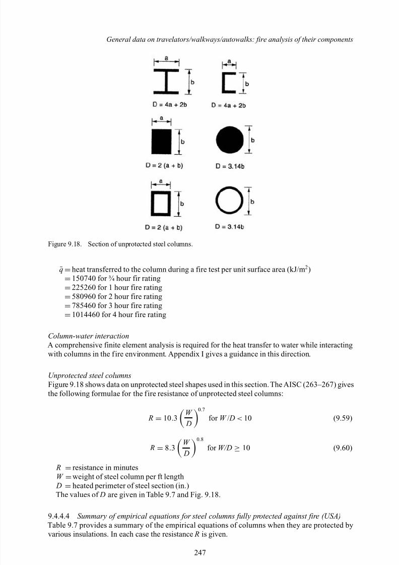
8/10/2019 Lifts Elevators Escalators and Moving Walkways Travelators 2DE2
http://slidepdf.com/reader/full/lifts-elevators-escalators-and-moving-walkways-travelators-2de2 58/169
General data on travelators/walkways/autowalks: fire analysis of their components
Figure 9.18. Section of unprotected steel columns.
¯q =heat transferred to the column during a fire test per unit surface area (kJ/m 2)
=150740 for ¾ hour fir rating
=225260 for 1 hour fire rating
=580960 for 2 hour fire rating=785460 for 3 hour fire rating
=1014460 for 4 hour fire rating
Column-water interactionA comprehensive finite element analysis is required for the heat transfer to water while interactingwith columns in the f ire environment. Appendix I gives a guidance in this direction.
Unprotected steel columnsFigure 9.18 shows data on unprotected steel shapes used in this section.The AISC (263–267) gives
the following formulae for the f ire resistance of unprotected steel columns:
R = 10 .3W D
0.7
for W / D < 10 (9.59)
R = 8.3W D
0.8
for W/D ≥ 10 (9.60)
R =resistance in minutesW =weight of steel column per ft length D
=heated perimeter of steel section (in.)
The values of D are given in Table 9.7 and Fig. 9.18.
9.4.4.4 Summary of empirical equations for steel columns fully protected against fire (USA)Table 9.7 provides a summary of the empirical equations of columns when they are protected byvarious insulations. In each case the resistance R is given.
247
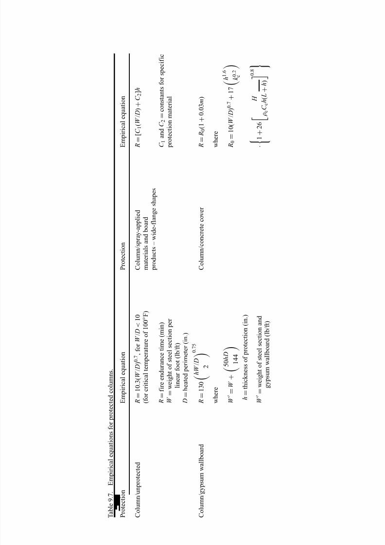
8/10/2019 Lifts Elevators Escalators and Moving Walkways Travelators 2DE2
http://slidepdf.com/reader/full/lifts-elevators-escalators-and-moving-walkways-travelators-2de2 59/169
T a b l e 9 . 7 . E m p i r i c a l e q u a t i o n s f o r p r o t e c t e d c o l u m
n s .
P r o t e c t i o n
E m p i r i c a l e q u a t i o n
P r o t e c t i o n
E m p i r i c a l e q u a t i o n
C o l u m n / u n p r o t e c t e d
R =
1 0 . 3 ( W / D ) 0 . 7 , f o r W / D < 1 0
C o l u m n / s p r a y - a p p l i e d
R =
[ C 1 ( W / D ) + C 2 ] h
( f o r c r i t i c a l t e m p e r a t u r e o f 1 0 0 ◦ F )
m a t e r i a l s a n d b o a r d
p r o d u c t s – w i d e - f l a n g e s h a p e s
R =
f i r e e n d u r a n c e t i m e ( m i n )
C 1 a n d
C 2 = c o n s t a n t s f o r s p e c i f i c
W = w e i g h t o f s t e e l s e c t i o n p e r
p r o t e c t i o n m a t e r i a l
l i n e a r f o o t ( l b / f t )
D =
h e a t e d p e r i m e t e r ( i n . )
C o l u m n / g y p s u m
w a l l b o a r d
R =
1 3 0 h W / D
2
0 . 7 5
C o l u m n / c o n c r e t e c o v e r
R = R 0 ( 1 + 0 . 0 3 m )
w h e r e
w h e r e
W
= W +
5 0 h D
1 4 4
R 0 =
1 0 ( W / D ) 0 . 7 + 1 7
h 1 . 6
k 0 . 2 c
h = t h i c k n e s s o f p r o t e c t i o n ( i n . )
W
= w e i g h t o f s t e e l s e c t i o n a n d
· 1 + 2 6
H
ρ c C c h ( L
+ h )
0 . 8
g y p s u m w a l l b o a r d ( l b / f t )
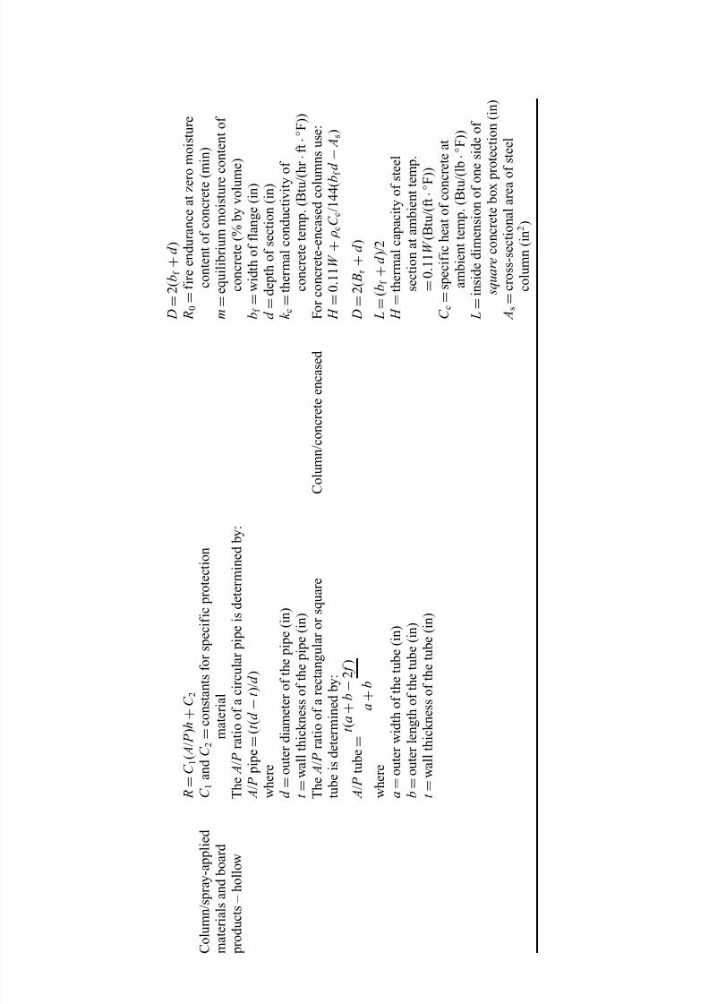
8/10/2019 Lifts Elevators Escalators and Moving Walkways Travelators 2DE2
http://slidepdf.com/reader/full/lifts-elevators-escalators-and-moving-walkways-travelators-2de2 60/169
D =
2 ( b f + d )
R =
C 1 ( A / P ) h + C 2
R 0 =
f i r e e n d u r a n c e a t z e r o
m o i s t u r e
C o l u m n / s p r a y - a p p l i e d
C 1 a n d
C 2 = c o n s t a n t s f o r s p e c i f i c p r o t e c t i o n
c o n t e n t o f c o n c r e t e ( m i n )
m a t e r i a l s a n d b o a r d
m a t e r i a l
m = e q u i l i b r i u m m o i s t u r e c o n t e n t o f
p r o d u c t s – h o l l o w
T h e A / P r a t i o o f a c i r c u l a r p i p e i s d e t e r m i n e d b y :
c o n c r e t e ( % b y v o l u m e )
A / P p i p e =
( t ( d − t ) / d )
b f = w i d t h o f f l a n g e ( i n )
w h e r e
d =
d e p t h o f s e c t i o n ( i n )
d = o u t e r d i a m e t e r o f t h e p i p e ( i n )
k c = t h e r m a l c o n d u c t i v i t y o f
t = w a l l t h i c k n e s s o f t h e p i p e ( i n )
c o n c r e t e t e m p . ( B t u / ( h r · f t · ◦ F ) )
T h e A / P r a t i o o f a r e c t a n g u l a r o r s q u a r e
C o l u m n / c o n c r e t e e n c a s e d
F o r c o n c r e t e - e n c a s e d c o l u m n s u s e :
t u b e i s d e t e r m i n e d b y :
H =
0 . 1 1 W + ρ c C c / 1 4 4 ( b f
d −
A s )
A / P t u b e =
t ( a + b
− 2 f )
a + b
D =
2 ( B r + d )
w h e r e
L =
( b f + d ) / 2
a = o u t e r w i d t h o f t h e t u b e ( i n )
H = t h e r m a l c a p a c i t y o f s t e e l
b = o u t e r l e n g t h o f t h e t u b e ( i n )
s e c t i o n a t a m b i e n t t e m p .
t = w a l l t h i c k n e s s o f t h e t u b e ( i n )
= 0 . 1 1 W ( B t u / ( f t · ◦ F ) )
C c = s p e c i f i c h e a t o f c o n c r e t e a t
a m b i e n t t e m p . ( B t u / ( l b
· ◦ F ) )
L =
i n s i d e d i m e n s i o n o f o n e s i d e o f
s q u a r e c o n c r e t e b o x p r o t e c t i o n ( i n )
A s = c r o s s - s e c t i o n a l a r e a o f s t e e l
c o l u m n ( i n 2 )
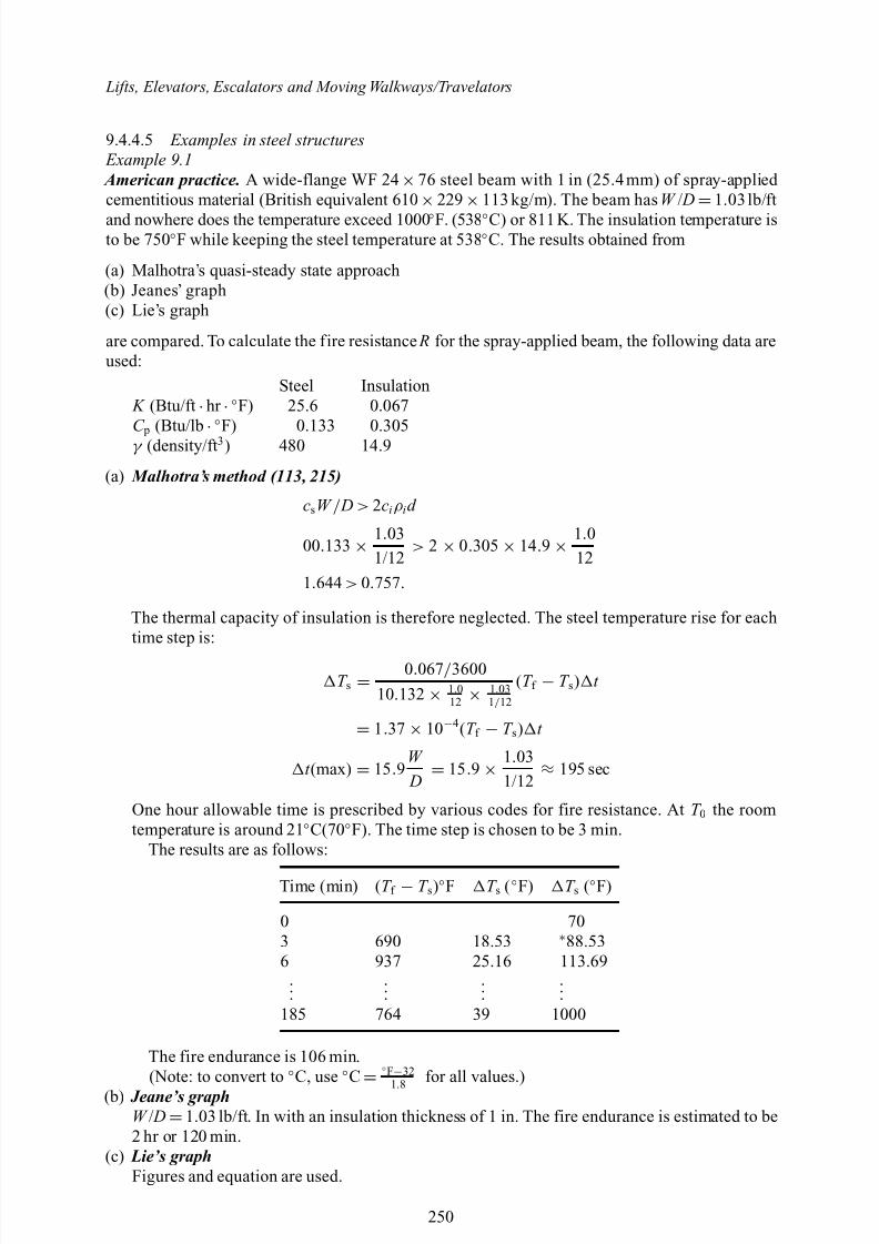
8/10/2019 Lifts Elevators Escalators and Moving Walkways Travelators 2DE2
http://slidepdf.com/reader/full/lifts-elevators-escalators-and-moving-walkways-travelators-2de2 61/169
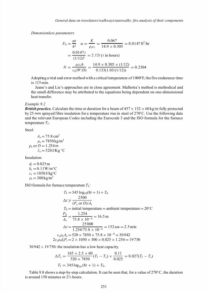
8/10/2019 Lifts Elevators Escalators and Moving Walkways Travelators 2DE2
http://slidepdf.com/reader/full/lifts-elevators-escalators-and-moving-walkways-travelators-2de2 62/169
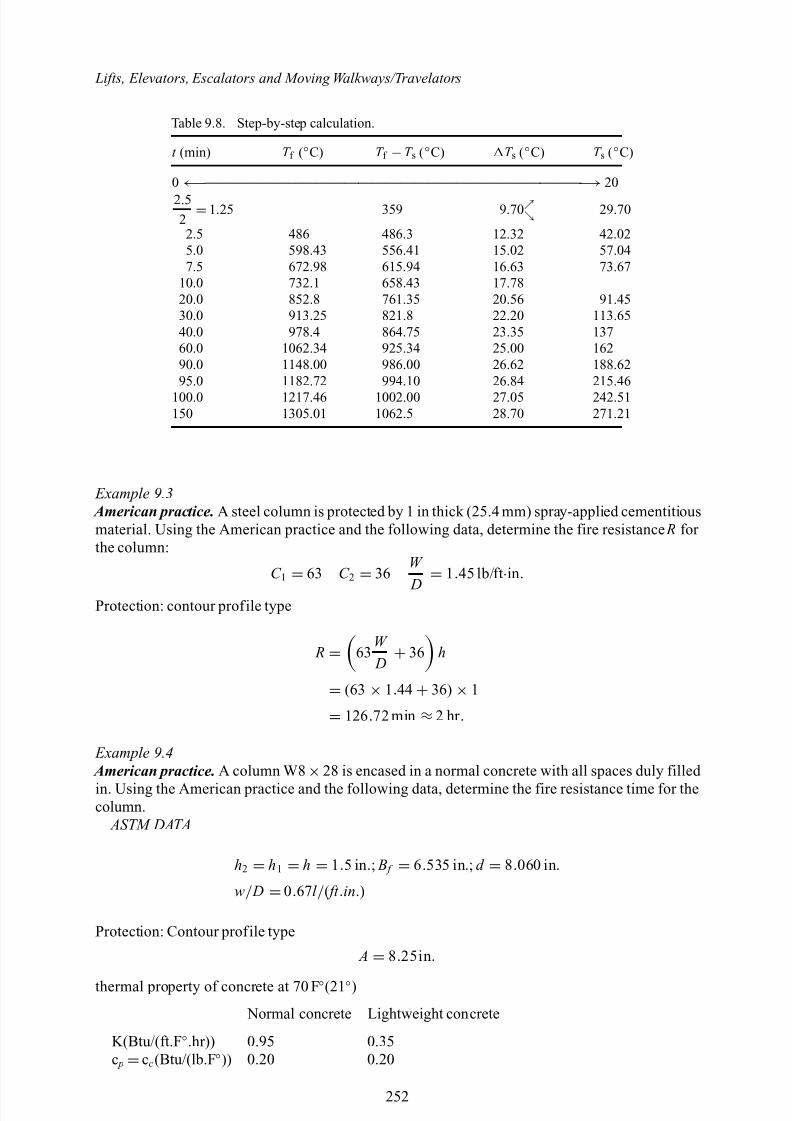
8/10/2019 Lifts Elevators Escalators and Moving Walkways Travelators 2DE2
http://slidepdf.com/reader/full/lifts-elevators-escalators-and-moving-walkways-travelators-2de2 63/169
Lifts, Elevators, Escalators and Moving Walkways/Travelators
Table 9.8. Step-by-step calculation.
t (min) T f (◦C) T f −T s (◦C) T s (◦C) T s (◦C)
0
←− ———————————————————————————
−→20
2.52 =1.25 359 9.70 29.70
2.5 486 486.3 12.32 42.025.0 598.43 556.41 15.02 57.047.5 672.98 615.94 16.63 73.67
10.0 732.1 658.43 17.7820.0 852.8 761.35 20.56 91.4530.0 913.25 821.8 22.20 113.6540.0 978.4 864.75 23.35 13760.0 1062.34 925.34 25.00 16290.0 1148.00 986.00 26.62 188.6295.0 1182.72 994.10 26.84 215.46
100.0 1217.46 1002.00 27.05 242.51150 1305.01 1062.5 28.70 271.21
Example 9.3 American practice. A steel column is protected by 1 in thick (25.4 mm) spray-applied cementitiousmaterial. Using the American practice and the following data, determine the fire resistance R for the column:
C 1
= 63 C 2
= 36
W
D = 1.45 lb/ft
·in .
Protection: contour profile type
R = 63W D + 36 h
= (63 × 1.44 + 36) × 1
= 126 .72 min ≈ 2 hr .
Example 9.4 American practice. A column W8
×28 is encased in a normal concrete with all spaces duly filled
in. Using the American practice and the following data, determine the fire resistance time for thecolumn.
ASTM DATA
h2 = h1 = h = 1.5 in .; B f = 6.535 in .; d = 8.060 in .
w/ D = 0.67l / ( ft .in .)
Protection: Contour profile type
A = 8.25in .
thermal property of concrete at 70 F ◦(21◦)
Normal concrete Lightweight concrete
K(Btu/(ft.F ◦.hr)) 0.95 0.35c p =cc (Btu/(lb.F ◦)) 0.20 0.20
252
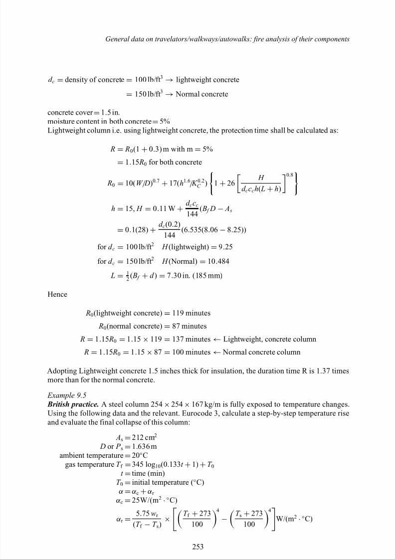
8/10/2019 Lifts Elevators Escalators and Moving Walkways Travelators 2DE2
http://slidepdf.com/reader/full/lifts-elevators-escalators-and-moving-walkways-travelators-2de2 64/169
General data on travelators/walkways/autowalks: fire analysis of their components
d c = density of concrete = 100 lb/ft 3 → lightweight concrete
= 150 lb/ft3
→ Normal concrete
concrete cover =1.5 in.moisture content in both concrete =5%Lightweight column i.e. using lightweight concrete, the protection time shall be calculated as:
R = R0(1 + 0.3) m with m = 5%
= 1.15 R0 for both concrete
R0 = 10( W / D)0.7 + 17(h1.6/ K 0.2C ) 1 + 26
H d ccch( L
+ h)
0.8
h = 15, H = 0.11 W + d ccc
144( B f D − A s
= 0.1(28) + d c(0 .2)
144(6 .535(8 .06 − 8.25))
for d c = 100 lb/ft 2 H (lightweight) = 9.25
for d c = 150 lb/ft 2 H (Normal) = 10 .484
L = 12 ( B f + d ) = 7.30 in. (185 mm)
Hence
R0(lightweight concrete) = 119 minutes
R0(normal concrete) = 87 minutes
R = 1.15 R0 = 1.15 × 119 = 137 minutes ← Lightweight, concrete column
R = 1.15 R0 = 1.15 × 87 = 100 minutes ← Normal concrete column
Adopting Lightweight concrete 1.5 inches thick for insulation, the duration time R is 1.37 timesmore than for the normal concrete.
Example 9.5 British practice. A steel column 254 ×254 ×167 kg/m is fully exposed to temperature changes.Using the following data and the relevant. Eurocode 3, calculate a step-by-step temperature riseand evaluate the final collapse of this column:
As =212 cm 2
D or P s =1.636 mambient temperature =20◦C
gas temperature T f =345 log 10 (0.133 t +1) +T 0t =time (min)
T 0
=initial temperature ( ◦C)
α =α c +α r
α c =25W/(m 2 ·◦C)
α r = 5.75 wr
(T f − T s) ×T f + 273
100
4
−T s + 273
100
4
W/(m 2 ·◦C)
253
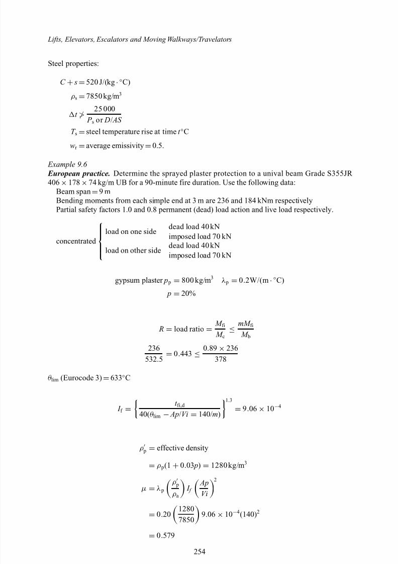
8/10/2019 Lifts Elevators Escalators and Moving Walkways Travelators 2DE2
http://slidepdf.com/reader/full/lifts-elevators-escalators-and-moving-walkways-travelators-2de2 65/169
Lifts, Elevators, Escalators and Moving Walkways/Travelators
Steel properties:
C + s=520 J/(kg ·◦C)
ρ s =7850 kg/m3
t ≯25 000
P s or D/ AS
T s =steel temperature rise at time t ◦C
wr =average emissivity =0.5.
Example 9.6 European practice. Determine the sprayed plaster protection to a unival beam Grade S355JR 406 ×178 ×74 kg/m UB for a 90-minute fire duration. Use the following data:
Beam span
=9 m
Bending moments from each simple end at 3 m are 236 and 184 kNm respectivelyPartial safety factors 1.0 and 0.8 permanent (dead) load action and live load respectively.
concentrated
dead load 40 kNload on one side
imposed load 70 kNdead load 40 kN
load on other sideimposed load 70 kN
gypsum plaster p p = 800 kg/m 3 λ p = 0.2W/(m ·◦C)
p = 20%
R = load ratio = M fi M c ≤
mM fi M b
236532 .5 = 0.443 ≤
0.89 × 236378
θ lim (Eurocode 3) =633 ◦C
I f = t fi,d
40( θ lim − Ap/Vi = 140/m)
1.3
= 9.06 × 10⁻⁴
ρ p = effective density
= ρ p(1 + 0.03 p) = 1280kg/m 3
µ
= λ p
ρ p
ρ a I f
Ap
Vi
2
= 0.2012807850
9.06 × 10⁻⁴(140) 2
= 0.579
254
8/10/2019 Lifts Elevators Escalators and Moving Walkways Travelators 2DE2
http://slidepdf.com/reader/full/lifts-elevators-escalators-and-moving-walkways-travelators-2de2 66/169
General data on travelators/walkways/autowalks: fire analysis of their components
µ (0) = S d,f
Rd,F = KS d,f
Rd,F
µ (0) = 0.7 × 0.556 = 0.389
θ a,cr = 78 .38ln 1
0.967( µ 0)3.833 − 11/2
+ 482
= 624 ◦C.
For a 90-minute f ire duration, temperate =607 ◦C and the spray thickness should be 12 mm.Check
F w = (1 + 4µ )1/2 − 1
2µ = (1 + 4 × 0.389) 1/2 − 1
2 × 0.389 = 0.76
d P = thickness (m)
= λ p I f F w AP Vi
= 0.2 × 9.06 × 10−4 × 0.76(140)
= 0.0193 m
= 19 .3 mm .
Adopt 21 mm as proposed.
REFERENCES/BIBLIOGRAPHY
1. Merrett Cyriax Associates , The role of structural fire protection . Cement and Concrete Association,London, November 1969, p. 140.
2. Money to burn? Cement and Concrete Association, London. Leaflet Bpe. I, April 1970, p. 4.3. Taylor , H. D., Structural fire protection. Proceedings of theThird National Fire Protection Conference .
Fire Protection Association, London, 1968, pp. 76–82.4. Fire Prevention Design Guide : No. 4 in the series ‘Planning for fire safety in buildings’. Fire Protection
Association, London. EPA planning programme. FPA Journal No. 86 , April 1970, pp. 27–38.5. Report of the Departmental Committee on the Fire Service (Chairman: Sir Ronald Holroyd). HMSO,
London, May 1970, Cmnd. 4371, pp. 228.6. Fire losses for 1969 top £120 million. FPA Journal No. 86 , April 1970, p. 4.7. Spread of fire in buildings — some statistical studies. JoFRO (Joint Fire Research Organization Quar-
terly). Winter 1968, p. 6.Lee , P. G., Contribution to the discussion of S mith , W. J. Fire protection of industrial buildings. Journal of the Royal Society of Arts . January 1971, p. 102.
8. Silock ,A., Protecting buildings against fire — background to costs.TheArchitect’s Journal InformationLibrary, 13 December 1967.
9. Srother -Smith , N. C., Code of precautions for industry, The Times . Monday 2 June 1969. Fire Pro-tection supplement, p. 1. Contributor to the discussion at the National IFPA/BFSA Conference, 18 November 1970, London. Advertisements for Colt Heating and Ventilation.
10. A hot three hundred million . TheAFA Group, London. (Seealso The Engineer , 18 September1969, p. 9.)11. SASCO bounce back. New Electronics , 19 August, 1969, p. 17.12. SASCO are back together again. SASCO Electronic News , Vol. 4, September 1969, p. 1.13. FPA Journal No. 86, April 1970, pp. 39–52.14. D oublet , A. R., Promotion of f ire protection by insurers. Proceedings of the Third National Fire
Prevention Conference . Fire Protection Association, London, 1968, pp. 14, 15.15. Fire reinsurance — some solutions . The Mercantile and General Reinsurance Company Limited, August
1970, p. 8.
255
8/10/2019 Lifts Elevators Escalators and Moving Walkways Travelators 2DE2
http://slidepdf.com/reader/full/lifts-elevators-escalators-and-moving-walkways-travelators-2de2 67/169
Lifts, Elevators, Escalators and Moving Walkways/Travelators
16. L awson , D. I., Fire research in the United Kingdom. Second National conference on Fire . AustralianFire Protection Association, August 1968 (see also Institution of Fire Engineers Quarterly ). Also Fry ,J. F. and E veleigh , C. The behaviour of automatic fire detection systems. Fire Research Stations, F. R. Note 810/1970.
17. Sprinkler system shut down for maintenance: £2½ million fire. FPA Journal No. 86 , pp. 45 and 46.18. Thef ireatAmaljeverket. TekniskUkeblad. Vol. 115, No. 42,November 1968, pp.998–1000. (Translationavailable from National Translation Center.)
19. Planning guide to fire safety when you have outside contractors in FPA Journal No. 89 , December 1970, pp. 211–218.
20. Early collapse of unprotected steel roof trusses at paper products warehouse. Fire , June 1969, p. 40.21. The behaviour of steel in fire— what is the significance of the British Standard 476 furnace test? JoFRO
(Joint Fire Research Organization Quarterly), Autumn 1968, pp. 2–5.22. F orrest , J. C. M. A warehouse to resist fire. Concrete Vol. 3, No. 8, August 1969, pp. 315–323.23. L inblad , A., P ettersson , O., Schmidt , B. and O deen , K., Fire in Warehouse No. 6 in the Free Port
of Stockholm. ICE Monthly , July 1969, pp. 326–336.24. The Reinstatement of Co-operative House. Simons Construction Group Ltd, October 1970, p. 12.
25. Report of a meeting on ‘The reinstatement of concrete construction after a fire’. Concrete Vol. 5, No. 4,April 1971, pp. 115–117.26. Effect of fireon Glasgow store. Civil Engineering and PublicWorks Review Vol. 60, No. 710, September
1965, pp. 1287, 1289.27. F acaoaru , I., Non-destructive testing of concrete in Romania. Symposium on non-destructive testing
of concrete and timber, 11–12 June 1969. Institution of Civil Engineers , Paper No. 4, pp. 23–33.28. S omerville , G., Load tests on Smallbrook Ringway Bridge, Birmingham . Cement and Concrete
Association, July 1969, Technical Report TRA 422.29. W illiamson , T. G., In Evaluation, Maintenance, and Upgrading of Wood Structures . American Society
of Civil Engineers, NewYork, 1982.30. D o , M. H. and S pringer , G. S., J. of Fire Sci. , 1, 1983, p. 271.31. D o , M. H. and S pringer , G. S., J. of Fire Sci. , 1, 1983, p. 285.
32. D o , M. H. and S pringer , G. S., J. of Fire Sci. , 1, 1983, p. 297.33. DCA No. 2, Design of Fire-Resistive Exposed Wood Members . American Forest & Paper Association,Washington, DC, 1985.
34. American Institute of Timber Construction, Timber Construction Manual. John Wiley and Sons, NewYork, 1985.
35. C arling , O., Study Report No. 18. Building Research Association of New Zealand, Judgeford, 1989.36. Wood Handbook: Wood as an Engineering Material (USDA Agr. Hdbk. No. 72) . Superintendent of
Documents, Washington, DC, 1987.37. G erhards , C. C., Wood and Fiber , 14, 1982, p. 4.38. B eall , F. C., In Structural Use of Wood in Adverse Environments . Van Nostrand Reinhold, New York,
1982.39. O stman , B. A.-L., Wood Sci. Tech. , 19, 1985, p. 103.
40. R agland , K. W., A erts , D. J. and B aker , A. J., Bioresource Technology , 37, 1991, p. 161.41. ASTME-119-88, StandardTestMethods forFireTestsof BuildingConstruction andMaterials .AmericanSociety for Testing and Materials, Philadelphia, 1988.
42. B letzacker , R. W., Effect of Structural Restraint on the Fire Resistance of Protected Steel Beam Floor and Roof Assemblies . Ohio State Univ., Columbus, 1966.
43. B oring , D., Spence , J. and Wells , W., Fire Protection Through Modern Building Codes . AmericanIron and Steel Institute, Washington, DC, 1981.
44. J eanes , D. C., Technical Report 84-1. Society of Fire Protection Engineers, Boston, 1984.45. A brams , M. S., ASTM STP 685 . American Society for Testing and Materials, Philadelphia, 1979.46. H armarthy , T. Z., NRCC 20956 (DBR Paper No. 1080) . National Research Council of Canada,
Ottawa, 1983.47. L ie , T. T., Fire and Buildings . Applied Science, London, 1972.
48. Lie
, T. T. and Stanzak
, W. W., Eng. J. , 57, 1974, pp. 5/6.49. B oring , D. F., An Analytical Evaluation of the Structural Response of Simply Supported. ThermallyUnrestrained Structural Steel Beams Exposed to the Standard Fire Endurance Test , Master’s Thesis,Ohio State University, Columbus, 1979.
50. L indberg , R. A., Processes and Materials of Manufacture. Allyn and Bacon, Inc., Boston, 1978, p. 46.
256
8/10/2019 Lifts Elevators Escalators and Moving Walkways Travelators 2DE2
http://slidepdf.com/reader/full/lifts-elevators-escalators-and-moving-walkways-travelators-2de2 68/169
General data on travelators/walkways/autowalks: fire analysis of their components
51. J eanes , D. C., Methods of Calculating Fire Resistance of Steel Structures , Engineering Applications of Fire Technology Workshop, SFPE, Boston, 1980.
52. M alhotra , H. L., Design of Fire-Resisting Structures . Chapman and Hall, 1982.53. H armathy , T. Z., ASME J. of Basic Eng ., 1967, p. 89.
54. H armathy , T. Z., ASTM STP 422 . American Society for Testing and Materials, Philadelphia, 1967.55. Fire Resistant Steel Frame Construction . American Iron and Steel Institute, Washington, DC, 1974.56. Designing Fire Protection for Steel Columns. American Iron and Steel Institute, Washington, DC, 1980.57. S tanzak , W. W. and L ie , T. T., Fire Tests on Protected Steel Columns with Different Cross-Sections .
National Research Council of Canada, Ottawa, 1973.58. PABCO, Pabco Super Firetemp Fireproofing Board Fire Protection Guide , PABCO, Ruston, LA, 1984.59. S eigel , L. G., Fire Tech ., 1970, p. 6.60. S eigel , L. G., Matls. Res. and Standards , February 1970, p. 4.61. Standard Building Code Congress, South Standard Building Code , SSBC, Birmingham, 1985.62. L ie , T. T. and S tanzak , W. W., Eng. J. Am. Inst. Steel Const. , 34d Qtr., 1973.63. Designing Fire Protection for Steel Beams . American Iron and Steel Institute, Washington, DC, 1985.64. Manual of Steel Construction . American Institute of Steel Construction, New York, 1981.
65. Fire Resistance Directory . Underwriters Laboratories, Northbrook, 1994.66. Designing Fire Protection for Steel Trusses . American Iron and Steel Institute, Washington, DC, 1980.67. Fire Resistance Design Manual . Gypsum Association, Evanston, 1984.68. S tanzak , W. W., Technical Trans. 1425. National Research Council of Canada, Ottawa, 1971.69. S tanzak , W. W., and H armathy , T. Z., Fire Tech ., 4, 1968, p. 4.70. P ettersson , O., M agnusson , S. and T hor , J., Bulletin 52, Lund Institute of Technology, Lund,
Sweden, 1976.71. Fire-Safe Structural Steel. A Design Guide . American Iron and Steel Institute, Washington,
DC, 1979.72. L aw , M., AISC Eng. J ., 2nd Qtr., 1978.73. B ond , G. V. L., Fire and Steel Construction — Water Cooled Hollow Columns . Constrado, 1974.74. L ie , T. T. and H armathy , T. Z., Fire Study No. 28 . National Research Council of Canada,
Ottawa, 1972.75. Z ienkewicz , O. C., The Finite Element Method. McGraw-Hill, New York, 1983.76. P aulsson , M., TASEF -2, Lund Institute of Technology, Lund, Sweden, 1983.77. Iding , R. H., N izamuddin , Z. and B resler , B., UCB FRB 77-15 . University of California, Berkeley,
1977.78. A nderberg , A., PC-TEMPCALC . Institutet for Brandteknisks Fragor, Sweden, 1985.79. M ilke , J. A., Estimating Fire Resistance of Tubular Steel Columns , Proceedings of Symposium on
Hollow Structural Sections in Building Construction. ASCE, Chicago, 1985.80. B ardell , K., ASTM STP 826 . American Society for Testing and Materials, Philadelphia, 1983.81. G ross , D., NBSIR 85-3223 . National Bureau of Standards, Gaithersburg, 1985.82. R obertson , A. F. and R yan , J. V., J. of Res ., 63C, 1959, p. 2.83. V innakota , S., Calculation of the Fire Resistance of Structural Steel Members. ASCE Spring
Meeting, 1978.84. K ruppa , J., J of Struc. Div., ASCE , 1979, p. 105.85. European Convention for Constructional Steelwork, Technical Committee 3, European Recommenda-
tions for the Fire Safety of Steel Structures . Elsevier, Amsterdam, 1983.86. L ie , T. T. and S tanzak , W. W., AISC Eng . J ., 13, 1976, p. 2.87. C hajes , A., Principles of Structural Stability Theory . Prentice-Hall, Englewood Cliffs, NJ, 1974.88. J eanes , D. C., F. Safety J ., 9, 1985, p. 1.89. NFPA 251, Standard Methods of Fire Tests of Building Construction and Materials . National Fire
Protection Association, Quincy, 1990.90. UL 263, Fire Tests of Building Construction and Materials . Underwriters Laboratories, Northbrook,
1992.91. Specification for the Design, Fabrication, and Erection of Structural Steel for Buildings . American
Institute of Steel Construction, NewYork, 1978.92. L ie , T. T. (ed.), Structural Fire Protection . American Society of Civil Engineers, NewYork, 1992.93. International Fire Engineering Design for Steel Structures: State of the Art. International Iron and Steel
Institute, Brussels, 1993.94. G amble , W. L., Predicting Protected Steel Member Fire Endurance Using Spreadsheet Programs, Fire
Technology , 25, 3, 1989, pp. 256–273.
257
8/10/2019 Lifts Elevators Escalators and Moving Walkways Travelators 2DE2
http://slidepdf.com/reader/full/lifts-elevators-escalators-and-moving-walkways-travelators-2de2 69/169
Lifts, Elevators, Escalators and Moving Walkways/Travelators
95. S tubbleeld , R. and E dwards , M. L., NODES-T3: Making FIRES-T3 a Little Easier, Departmentof Fire Protection Engineering, University of Maryland, College Park, 1991 (unpublished).
96. T omecek , D. V. and M ilke , J. A., A Study of the Effect of Partial Loss of Protection on the FireResistance of Steel Columns, Fire Technology , 29, 1, 1993, pp. 3–21.
97. Supplement to the National Building Code of Canada , National Research Council of Canada, Ottawa,1990.98. DCA No. 4: Component Additive Method (CAM) for Calculating and Demonstrating Assembly Fire
Endurance . American Forest & Paper Association, Washington, DC, 1991.99. Wood and Fire Safety . Canadian Wood Council, Ottawa, 1991.
100. W hite , R. H., in ASTM STP 826 . American Society for Testing and Materials, Philadelphia, 1983.101. R ichardson , L. R. and C ornelissen , A. A., Fire and Materials , 11, 1987, p. 191.102. W hite , R. H., J. of Test. and Eval. , 14, 1986, p. 97.103. Fire Resistance of Wood Structures . Technical Research Centre of Finland, Helsinki, 1980.104. G ardner , W. D. and S yme , D. R., Technical Report No. 5. N.S.W. Timber Advisory Council Ltd.,
Sydney, 1991.105. F ung , F. C. W., NBSIR 77-1260 . National Bureau of Standards, Washington, DC, 1977.
106. G ammon , B. W., Reliability Analysis of Wood-Frame Wall Assemblies Exposed to Fire , Dissertation,University of California, Berkeley, 1987.107. M ehaffey , J. R. and S ultan , M. A., in Proc. of First International Fire and Materials Conference .
Interscience Communications Ltd., London, 1992.108. B rowne , F. L., Report No. 2136. USDA Forest Service, Forest Product Lab., Madison, 1958.109. S chaffer , E. L., Research Note FPL-145 . USDA Forest Service, Forest Product Lab., Madison,
1966.110. H all , G. S., S aunders , R. G., A llcorn, R. T., Jackman , P. E., H ickey , M. W. and F itt , R., Fire
Performance of Timber — A Literature Survey . Timber Research and Development Association, HighWycombe, 1971.
111. S chaffer , E. L., Wood and Fiber , 9, 1977, p. 145.112. H advig , S., Charring of Wood in Building Fires . Technical University of Denmark, Lyngby, 1981.
113. M alhotra , H. L., Design of Fire-Resisting Structures . Surrey University Press, London, 1982.114. S chaffer , E. L., Research Paper FPL 69 . USDA Forest Service, Forest Product Lab., Madison, 1967.115. W hite , R. H., Fire Technology , 28, 1982, p. 5.116. L ache , M., Holz-Zentralblatt , 117, 1991, p. 473.117. C olier , P. C. R., Study Report No. 42 . Building ResearchAssociation of New Zealand, Judgeford, 1992.118. K anury , A. M. and H olve , D. J., NBS-GCR 76-50 . National Bureau of Standards, Washington, DC,
1975.119. N oren , B. J. and O stman , B. A.-L., in Fire Safety Science — Proceedings of the First International
Symposium . Hemisphere, New York, 1986.120. K erksen -Bradley , M., In Proc. of Oxford Fire Conference . Timber Research and Development
Association, High Wycombe, 1993.121. S chaffer , E. L., J. Fire and Flamm ., 1, 1974, p. 96.
122. T ran , H. C. and W hite , R. H., Fire and Materials , 16, 1992, p. 197.123. M ikkola , E., In Fire Safety Science — Proceedings of the Third International Symposium . Elsevier Applied Science, London, 1991.
124. N ussbaum , R. M., J. Fire Sciences , 6, 1988, p. 290.125. P ettersson , O., M agnusson , S. E. and T hor , J., Publication 50 . Swedish Institute of Steel
Construction, Sweden, 1976.126. O leson , F. B. and K onig , J., Report No. 19210061 . Swedish Institute for Wood Technology Research
(Tratek), Stockholm, 1991.127. R oberts , A. F., In Thirteenth Symposium (Int.) on Combustion . The Combustion Institute, Pittsburgh,
1971.128. B amford , C. H., C rank , J. and M alan , D. H., Proc. of Camb. Phil. Soc., 46, 1946, p. 166.129. T homas , P. H., Fire Research Note No. 446 . Fire Research Station, Borehamwood, UK, 1960.
130. K ung
, H., Combustion and Flame , 18, 1972, p. 195.131. T amanini , F., In Appendix A of Factory Mutual Research Corporation Report No. 21011.7 . FactoryMutual Research Corp., Norwood, 1976.
132. A treya , A., Pyrolysis: Ignition and Fire Spread on Horizontal Surfaces of Wood , PhD Thesis, Harvard University, Cambridge, MA, 1983.
258
8/10/2019 Lifts Elevators Escalators and Moving Walkways Travelators 2DE2
http://slidepdf.com/reader/full/lifts-elevators-escalators-and-moving-walkways-travelators-2de2 70/169
General data on travelators/walkways/autowalks: fire analysis of their components
133. P arker , W. J., In Fire Safety Science — Proceedings of the Second International Symposium .Hemisphere, New York, 1989.
134. H avens , J. A., Thermal Decomposition of Wood , Dissertation, University of Oklahoma (1969).135. K nudson , R. M. and S chneiwind , A. P., Forest Prod. J. , 25, 1975, 23.
136. K ansa , E. J., P erlee , H. E. and C haiken , R. F., Comb. and Flame , 29, 1977, 311.137. H advig , S. and P aulsen , O. R., J. Fire and Flamm. , 1, 1976, p. 433.138. T inney , E. R., in Tenth Symposium (Int.) on Combustion . The Combustion Institute, Pittsburgh, 1965.139. W hite , R. H. and S chaffer , E. L., Wood and Fiber , 13, 1981, p. 7.140. W hite , R. H. and S chaffer , E. L., Fire Tech. , 14, 1978, p. 279.141. F redlund , B., Fire Safety J., 20 , 1993, p. 39.142. S chaffer , E. L., M arx , C. M., B ender , D. A. and W oeste , F. E., Research Paper FPL 467 . USDA
Forest Service, Forest Product Lab., Madison, 1986.143. N oren , J., Report 1 8810066 . Swedish Institute for Wood Technology (Tratek), Stockholm, 1988.144. S chaffer , E. I., Research Paper FPL 450 . USDA Forest Service, Forest Product Lab., Madison, 1984.145. I maizumi , C., Norsk Skogind , 16, 1962, p. 140.146. L ie , T. T., Can. J. of Civil Engg. , 4 1977, p. 160.
147. O deen , K., In Fire and Structural Use of Timber in Buildings . HMSO, London, 1970.148. F redlund , B., Report No. 79-5 , Lund Institute of Technology, Lund, 1979.149. M eyer-ottens , C., In Three Decades of Structural Fire Safety . Building Research Establishment, Fire
Research Station, Borehamwood, UK, 1983.150. P ettersson , O., In Three Decades of Structural Fire Safety . Building Research Establishment, Fire
Research Station, Borehamwood, UK, 1983.151. B arthelemy , B. and K ruppa , J., Resistance au Leu des Structures . Editions Eyrolles,
Paris, 1978.152. K irpichenkov , G. M. and R omanenkov , I. G., NSBIR 80-2188 . National Bureau of Standards,
Washington, DC, 1980.153. O deen , K., Fire Tech. , 21, 1985, p. 34.154. W oeste , F. E. and S chaffer , E. L., Fire and Matls. , 3, 1979, p. 126.
155. W oeste , F. E. and S chaffer , E. I., Research Paper FPL 386. USDA Forest Service, Forest ProductLab., Madison, 1981.156. W hite , R. H., S chaffer , E. L. and W oeste , F. E., Wood and Fiber , 16, 1984, p. 374.157. S chaffer , E. L., W hite , R. H. and W oeste , F. E., In Proc. 1988 International Conference on Timber
Engineering . Forest Products Research Society, Madison, 1988.158. W hite , R. H., C ramer , S. M. and S hrestha , D., Research Paper FPL 522 . USDA, Forest Service,
Forest Products Lab., Madison, 1993.159. S chaffer ,E.L.andW oeste , F. E., In Proceedings, Metal PlateWoodTrussConference. Forest Products
Research Society, Madison, 1981.160. K ing , E. G. and G lowinski , R. W., Forest Prod. J. , 38(10), 1988, p. 31.161. B ender , D. A., W oeste , F. E., S haffer , E. L. and M arx , C. M., Research Paper FPL 460. USDA
Forest Service, Forest Prod. Lab., Madison, 1985.
162. S chaffer , E. L., Structural fire design: wood. U.S. Forest Service Research Paper FPL 450 , U.S. Dept.Agri., For. Prod. Lab., Madison, WI, 1984.163. S chaffer , E. L., Effects of Pyrolytic Temperatures on the Longitudinal Strength of Dry Douglas-fir.
ASTM J. of Testing and Evaluation , 1(4), 1973, pp. 319–329.164. S chaffer , E. L., Influence of heat on the longitudinal creep of dry Douglas-fir. Structural Use of Wood
in Adverse Environments , Robert W. Meyer, and Robert M. Kellogg, eds. Van Nostrand Reinhold Co., NewYork, NY, 1978.
165. S chaffer , E. L., State of structural timber fire endurance. Wood and Fiber , 1977.166. T ang , W. K., Effect of inorganic salts on pyrolysis of wood, alpha-cellulose, and lignin determined by
dynamic thermogravimetry. U.S. Forest Service Research Paper FPL-71 , U.S. Dept. Agri., For. Prod.Lab., Madison, WI, 1967.
167. USDA Agr. Hdbk. No. 72. Wood handbook: Wood as an engineering material. Superintendent of
Documents, Washington, DC, 1987.168. US Federal Emergency ManagementAgency, Multiprotection design manual , Fire Section, TR 20, Part3, Fire, Washington, DC, 1980,
169. A llen , D.E. and L ie , T. T., Further studies of the fire resistance of reinforced concrete columns. NRCC 14047 , National Research Council of Canada, Division of Building Research, Ottawa, 1974.
259
8/10/2019 Lifts Elevators Escalators and Moving Walkways Travelators 2DE2
http://slidepdf.com/reader/full/lifts-elevators-escalators-and-moving-walkways-travelators-2de2 71/169
Lifts, Elevators, Escalators and Moving Walkways/Travelators
170. American Society for Testing and Materials, Standard methods of fire tests of building constructionsand materials , Designation E119-83, Phildelphia, PA, 1985.
171. Atreya , A., Pyrolysis: ignition and fire spread on horizontal surfaces of wood . PhD Thesis , Harvard University, Cambridge, MA, 1983.
172. B ender , D. A., Woeste , F. E. and S chaffer , E. L., Reliability formulation for the strength and fireendurance of glued-laminated beams. Research Paper FPL 460 , U.S. Department of Agriculture, ForestService, Forest Products Laboratory, Madison, WI, 1985.
173. B resler , B. and I ding , R. H. J., Effect of fire exposure on steel frame buildings. (Computer ProgramFASBUS II), Final Report, Vols. 1 and 2 , to American Iron and Steel Institute, Wiss, Janney, Elstner Associates, Inc., Emeryville, CA, 1982.
174. British Iron Steel Res. Assoc., Physical constants of some commercial steels at elevated temperatures.Butterworths, London, 1953.
175. C arling , O., Fire resistance of joint details in loadbearing timber construction – A literature survey.(Translated from the original Swedish by B. Harris and P. K. A. Yiu), BRANZ Study Report SR 18 ,Building Research Association of New Zealand, Judgeford, New Zealand, 1989.
176. CEC Research 7210-SA/502-REFAO/CAFIR. Computer assisted analysis of the fire resistance of steel
andcompositesteel — ConcreteStructures. (ComputerProgramCEFI-COSS), TechnicalReports RT1-6 ,Luxembourg.177. CTICM (Centre Technique Industriel de la Construction Métallique), Methode de prévision par le calcul
du compartement au feudes structuresen acier. (In French), D.T.U. (DocumentTechniqueUnifié), RevueConstruction Métallique , No. 3, 1982.
178. D o , M. H. and S pringer , G. S., Mass loss of and temperature distribution in southern pine and Douglasfir in the range 100 to 800 ◦C. J. of Fire Sci ., 1, 1983, pp. 271–284.
179. D o , M. H. and S pringer , G. S., Model for predicting changes in the strength and moduli of timber exposed to elevated temperatures. J. of Fire Sci ., 1, 1983, pp. 285–296.
180. D o , M. H. and S pringer , G. S., Failure time of loaded wooden beams during fire. J. of Fire Sci ., 1,1983, pp. 297–303.
181. D usinberre , G. M., Heat transfer calculations by finite differences. International Textbook Co.,
Scranton, PA, 1961.182. F orsen , N. E., STEELFIRE — Finite element program for non-linear analysis of steel frames exposed to fire. Users Manual, Multiconsult A/S, Oslo, Norway, 1983
183. F redlund , B., Structural designof fire exposed rectangular laminate woodbeams with respect to lateral buckling. Report No. 79-5 , Department of Structural Mechanics, Lund Institute of Technology, Lund,Sweden, 1979.
184. F redlund , B., A model for heat and mass transfer in timber structure during fire. Report LUTVDG/(TVBB-1003) , Lund University, Department of Fire Safety Engineering, Lund, Sweden,1988.
185. F redlund , B., Calculation of f ire resistance of wood based boards and wall construction. Report SE-LUTVDG/(TVBB-3053) , Lund University, Department of Fire Safety Engineering, Lund, Sweden,1990.
186. G ammon , B. W., Reliability analysis of wood frame wall assemblies in fir. University of California,Berkeley, CA, 1987.187. G room , A. J., Modelling of heat transfer in composite structures at fir temperatures. Proceedings of
International Symposium on Fire Engineering Fire Building Structures and Safety , Building ResearchAssociation of New Zealand (Reprints, No. 93), Judgeford, New Zealand, 1989.
188. H advig , S. and P aulsen , O. R., One-dimensional charring rates in wood. J. Fire and Flamm ., 1, 1976, pp. 433–449.
189. H aksever , A., Rechnerische Untersuchung des Tragverhaltens von einfach statisch unbestimmtenStahlbetonrahmen unter Brandbeanspruchung. (In German), Institut für Baustoff-kunde und Stahlbe-tonbau der Technischen Universität Braunschweig, 1975.
190. H aksever , A., Zur Frage des Trag- und Verformungsverhaltens ebene Stahlbetonrahmen im Brandfall.(In German), Institut für Baustoffkunde und Stahlbetonbau der Technischen Universität Braunschweig,
Heft 35, Braunschweig, 1977.191. H armathy , T. Z.,Thermal performanceof concrete masonrywalls in fire. SpecialTechnicalPublication No. 464. American Society for Testing and Materials, Philadelphia, PA, 1970.
192. H avens , J. A., Thermal Decomposition of Wood , Dissertation, University of Oklahoma, 1969.193. H ognestad , E., A study of combined bending and axial load in reinforced concrete members. Bulletin
No. 399 . University of Illinois Engineering Experiment Station, Urbana, IL, 1951.
260
8/10/2019 Lifts Elevators Escalators and Moving Walkways Travelators 2DE2
http://slidepdf.com/reader/full/lifts-elevators-escalators-and-moving-walkways-travelators-2de2 72/169
General data on travelators/walkways/autowalks: fire analysis of their components
194. I ding , R., B resler , B. and N izamuddin , Z., FIRES-T3, A computer program for the fire response of structures. Report No. UCB FRG 77-5 , University of California, Fire Research Group, Berkeley, CA,1977.
195. I maizumi , D., Stability in fire of protected and unprotected glued laminated beams. Norw. Inst. Wood
Working Wood Technol ., Meddelelse (18), 1962.196. I ngberg , S. H. and S ale , P. D., Compressive Strength and Deformation of Structural Steel and Cast-Iron Shapes at Temperatures up to 950 ◦C (1742 ◦F). Proceedings of the American Society for Testing and Materials , 26(II), Philadelphia, PA, 1926.
197. J eanes , D. C., Computer modeling the fire endurance of floor systems in steel framed buildings. ASTMSTP 882, T.Z. Harmathy, ed. American Society for Testing and Materials, Philadelphia, PA, 1985.
198. K ansa , E. J., P erlee , H. E. and C haiken , R. F., Mathematical model of wood pyrolysis includinginternal forced convection. Comb. and Flame , 29, 1977, pp. 311–324.
199. K anury , A. M., H olve , D. J., NBS – GCR 76-50. National Bureau of Standards, Washington,DC, 1975.
200. K ing , E. G. and G lowinski , R. W., A rationalized model for calculating the fire endurance of wood beams. Forest Products Journal , 38(10), 1988, pp. 31–36.
201. K lingsch , W., Traglastberechnung thermisch belasteter Stahlbetondruckglieder unter Anwendung einer zwei- und dreidimensionalen Diskretisierung. (In German), Institut für Baustoffkunde und Stahlbetonbau der Technischen Universität Braunschweig, 1975.
202. K nudson , R. M. and S chneiwind , A. P., Performance of structural wood members exposed to fire. For. Prod. J. , 25(2), 1975, pp. 23–32.
203. K onicek , L. and L ie , T.T., Fire tests on protected steel columns under different fire severities. FireStudy No. 34 . NRCC 14170, Division of Building Research, National Research Council of Canada,Ottawa, 1974.
204. K onig , J. and K allsner , B., The influence of the support conditions on loadbearing capacity of axially loaded wood studs under simulated fire exposure. Proceedings of the 1988 International Conference onTimber Engineering , Seattle, WA. Forest Products Research Society, Madison, WI, 1988, pp. 423–421.
205. L ie , T. T., A method for assessing the fire resistance of laminated timber beams and columns. Canadian Journal of Civil Engineering , 4(2), 1977, pp. 161–169.206. L ie , T. T., Temperature distributions in fire-exposed building columns. Journal of Heat Transfer , 99(1),
1977.207. L ie , T. T., Calculation of the f ire resistance of composite concrete floor and roof slabs. FireTechnology ,
14(1), 1978, pp. 28–45.208. L ie , T. T., A procedure to calculate fire resistance of structural members. Fire and Materials , 8(1), 1984,
pp. 40–48.209. L ie , T. T. and H armathy , T.Z., A numerical procedure to calculate the temperature of protected steel
columns exposed to fire. Fire Study No. 28 . NRCC 12535, Division of Building Research, NationalResearch Council of Canada, Ottawa, 1972.
210. L ie , T. T., L in , T. D., A llen , D. E. and A brams , M. S., Fire resistance of reinforced concrete
columns. Technical Paper No. 378 . Division of Building Research, National Research Council of Canada, Ottawa, 1984.211. L iley , P. E., Physical and chemical data. Chemical/Engineering Handbook. McGraw-Hill, New York,
1963, p. 133.212. L iley , P. E., T ouloukian , Y.S. and G ambill , W. R., Physical and chemical data, chemical engineers
handbook . J. H. Perry (ed.), Sec. 3. McGraw-Hill, New York, 1963.213. L im , K. Y. S., K ing , A. B., Protected nailed gusset connections for glulam members. BRANZ Study
Report SR 29 , Building Research Association of New Zealand, Judgeford, New Zealand, 1990.214. M alhotra , H. L., Design of fire-resisting structures . Surrey University Press, London, 1982.215. N oren , J., Failureof structural timberwhenexposedto fire. Proceedings of the International Conference
on Timber Engineering . Forest Products Research Society, Madison, WI, 1988, pp. 397–406.216. O deen , K., Fire resistance of glued, laminated timber structures. Min. Technol. Fire Offices’ Comm.
Joint Fire Res. Org. Symp. No. 3 , Paper No. 2, HMSO, London, 1970.217. P arker , W. J., Fire Safety Science — Proceedings of the First International Symposium . Hemisphere, NewYork, NY, 1986.
218. P ettersson , O., Structural fire behavior — developments, trends . C. E. Grant and P. J. Pagni, eds., Proceedings of the First International Symposium, International Association for Fire Safety Science .Hemisphere Publishing Corporation, Washington, DC, 1986.
261
8/10/2019 Lifts Elevators Escalators and Moving Walkways Travelators 2DE2
http://slidepdf.com/reader/full/lifts-elevators-escalators-and-moving-walkways-travelators-2de2 73/169
Lifts, Elevators, Escalators and Moving Walkways/Travelators
219. P ettersson , O., J onsson , R., Reliability based design of fire exposed timber structures — State of art and summary design guide. Report LUTVDG/(TVBB-3040) , Lund University, Department of FireSafety Engineering, Lund, Sweden, 1988.
220. Q uast , U., H ass R. and R udolph , K., STABA-F ; A computer program for the determination of
load-bearing and deformation behaviour of uni-axial structural elements under f ire action. Institutfür Bausoffkunde, Massivbau und Brandschutz der Technischen Universität Braunschweig (1982/85),1984.
221. R eyer , E., Schlich , C., Investigations on the bending and lateral buckling of laminated wood gird-ers under fire exposure. Proceedings of the International Conference on Timber Engineering. ForestProducts Research Society, Madison, WI, 1988, pp. 407–422.
222. R itter , W., Die Bauweise Hennebique . (In German), Schweizerische Bauzeitung, Vol. 33, 1899.223. R oberts , A. F., The heat of reaction during the pyrolysis of wood. Combustion and Flame , 17, 1971.224. R ogowski , B. F. W., Charring of timber in fire tests. Min. Technol. Fire Offices’ Comm. Joint Fire Res.
Org. Symp. No. 3, Paper No. 4 . HMSO, London, 1970.225. S chaffer , E. L., An approach to the mathematical prediction of temperature rise within a semi-infinite
wood slab subjected to high temperature conditions. Pyrodynamics , 2, 1965, pp. 117–132.
226. S chaffer , E. L., Charring rate of selected woods — Transverse to grain. U.S. For. Serv. Res. Paper FPL69. U.S. Department of Agriculture, Forest Service, Forest Products Laboratory, Madison, WI, 1967.227. S chaffer , E. L., State of structural timber fire endurance. Wood and Fiber , 9(2), 1977, pp. 145–190.228. S chaffer ,E.L. ,M arx ,C.M.,B ender , D.A.andW oeste , F. E., Strength validation andf ireendurance
of glued-laminated timber beams. Research Paper FPL 467 . U.S. Department of Agriculture, ForestService, Forest Products Laboratory, Madison, WI, 1986.
229. S chaffer ., E. L. and W oeste , F. E., Reliability analysis of a fire-exposed unprotected floor truss. Pro-ceedings, Metal Plate Wood Truss Conference. Forest Products Research Society, Madison, WI, 1981, pp. 131–137.
230. S chaffer ., E. L. and W oeste , F. E., Second moment reliability of fire-exposed wood joist floor assemblies. Fire and Matls . 3(3), 1979, p. 126.
231. S chaffer ., E. L. and W oeste , F. E., Second moment reliability of fire-exposed wood joist floor
assemblies. Fire and Matls . 3(3), 1979, p. 126.232. S chaffer ., E. L. and W oeste , F. E., Reliability analysis of fire-exposed light-frame wood floor assemblies. Research Paper FPL 386. USDA Forest Service, Forest Products Lab, Madison,WI, 1981.
233. W hite , R. H. and S haffer , E. L., Application of CMA program to wood charring. Fire Tech ., 14(4),1989, pp. 279–290, 296.
234. W hite , R. H. and S haffer , E. L., Transient moisture gradient in fire-exposed wood slab. Wood and Fiber , 13(17), 1981, p. 296.
235. W hite , R. H. and S haffer , E. L., Replicate fire endurance tests of an unprotected wood joist floor assembly. Wood and Fiber , 16(3), 1984, pp. 374–390.
236. W ickstrom , U., TASEF-2, A computer program for temperature analysis of structures exposed tofire. Report No. 79-2 , LundInstituteofTechnology, Departmentof StructuralMechanics, Lund, Sweden,
1979.237. W illiams -Leir , G., Analytical equivalents of standard fire temperature curves. Fire Technology , 9(2),1973, pp. 132–136.
238. W illiams -Leir , G., Analytical equivalents of standard fire temperature curves. Fire Technology , 9(2),1973, pp. 132–136.
239. W itteveen , J., Twilt , L. and B ylaard , F. S. K., The stability of braced and unbraced frames atelevated temperatures. Second Int. Colloquium on Column Strength, Liege, Belgium, 1977.
240. Z ienkiewicz , O. C. and C heung , Y. K., The finite element method in structural and continuummechanics. McGraw-Hill Publishing Co. Ltd., London, 1967.
241. S chneider , U. and H aksever , A., Bestimmung der äquivalenten Branddauer von statisch bes-timmt gelagerten Stahlbetonbalken bei natürlichen Branden. (In German), Bericht des Instituts für Baustoffkunde und Stahlbetonbau der Technischen Universität Braunschweig, 1976.
242. Spiers
, H. M., Technical data on fuel , 6th Edition. World Press Conference, London, 1961.243. S tanzak , W. W. and L ie , T. T., Fire resistance of unprotected steel columns. Journal of the Structural Division, ASCE, 99 (ST5), 1973, p. 9719.
244. T inney , E. R., Tenth Symposium Int. on Combustion. The Combustion Institute, Pittsburg, PA, 1965.245. T rinks , W. and M awhinney , M. W., Industrial Furnaces . Carnegie Inst. Technology, Wiley, NewYork,
1981.
262
8/10/2019 Lifts Elevators Escalators and Moving Walkways Travelators 2DE2
http://slidepdf.com/reader/full/lifts-elevators-escalators-and-moving-walkways-travelators-2de2 74/169
General data on travelators/walkways/autowalks: fire analysis of their components
246. W hite , R. H., Charring rate of different wood species. PhD Dissertation, Madison, WI, University of Wisconsin, 1988.
247. W hite , R. H. and N ordheim , E. V., Charring rate of wood for ASTM E119 Exposure. FireTechnology ,28(1), 1992, pp. 5–30.
248. L ie , T. T., Fire and buildings. Applied Science Publishers Limited, London, 1972, pp. 9–11.249. L ie , T. T., Characteristic temperature curves for various fire severities. Fire Technology, 10(4), 1974, pp. 315–326.
250. M agnusson , S. E. and T helandersson , S., Temperature–time curves of complete process of firedevelopment. Theoretical study of wood fuel fires in enclosed spaces. Civil Engineering and Building Construction Series No. 65 . Acta Polytechnica Scandinavica, Stockholm, Sweden, 1970.
251. O deen , K.,Theoretical study of fire characteristics in enclosed spaces. Bulletin10 , Division of BuildingConstruction, Royal Institute of Technology, Stockholm, Sweden, 1963.
252. T homas , P. H., H eselden , A. J. M., Fully-developed fires in single compartments. Fire Research Note No. 923 , Building Research Establishment, Fire Research Station, Boreham-wood, U.K., 1972.
253. T homas , P. H., H eselden , A. J. M. and L aw , M., Fully-developed compartment fires; two kinds of behaviour. Fire Research Technical Paper No. 18. HMSO, London, 1967.
254. T suchiya , Y. and S umi , K., Computation of the behaviour of fire in an enclosure. Combustion and Flame , 16, 1971, p. 131.255. W illiams -Leir , G., Analytical equivalents of standard fire temperature curves. Fire Technology , 9(2),
1973, pp. 132–136.256. A brams , M. S., et al. , Fire endurance of continuous reinforced concrete beams. Preliminary Report
of the Tenth Congress of the International Association for Bridge and Structural Engineering. Portland Cement Association, Skokie, IL, 1976.
257. A brams , M. S. and G ustaferro , A. H., Fire endurance of two-course floors and roofs. Journal of the American Concrete Institute , 66(2), 1969, pp. 92–102.
258. A brams , M. S., G ustaferro , A. H. and S alse , E. A. B., Fire tests of concrete joist floors and roofs. Research and Development Bulletin No. RD006.01B . Portland Cement Association, Skokie, IL, 1971.
259. A llen , L. W. and H armathy , T. Z., Fire endurance of selected concrete masonry units . Journal of the
American concrete Institute, 69, 1985.260. AmericanConcreteInstitute, Guidefor determining thefireenduranceof concrete elements.ACI216R81,1987.
261. American Insurance Services Group, Fire resistance ratings. New York, 1985.262. American Iron and Steel Institute, Designing fire protection for steel trusses. Washington, DC, 1976.263. American Iron and Steel Institute, Designing fire protection for steel columns , Third Edition.
Washington, DC, 1980.264. American Iron andSteel Institute, Fire ResistanceRatings of Load-BearingSteel StudWalls. Washington,
DC, 1981.265. American Iron and Steel Institute, Designing fire protection for steel beams. Washington, DC, 1984.266. American Society for Testing and Materials, Standard Methods of Fire Tests of Building Construction
and Materials, ANSI/ASTM E119–83 . Philadelphia, PA, 1985.
267. Brick Institute of America, Technical notes on brick construction. Technical Note No. 16. McLean, VA,1974.268. Canadian StandardsAssociation, Code for the engineering design of wood, CSA standard 086 . Rexdale,
Ontario, 1984.269. C ulver , C. G., A ggarwal , V. and O ssenbruggen , P., Buckling of columns at elevated temperatures.
Journal of the Structural Division, ASCE , 99(ST4), 1973, pp. 715–726.270. F itzgerald , R. W., Structural integrity during fire. Fire Protection Handbook , National FireProtection
Association, 16th edn, Section 7, Chapter 8. Quincy, MA, 1986, pp. 7–82 to 7–108.271. F lemington , R. A., Fire protection of hollow structural section. Technical Bulletin 21. Stelco Inc.,
Toronto, Canada, 1980.272. G ustaferro , A. H., Temperature criteria at failure. Fire Test Performance, STP-464. American Society
for Testing and Materials, Philadelphia, PA, 1970, pp. 68–84.
273. Gustaferro
, A. H. and Selvaggio
, S. L., Fire endurance of simply-supported prestressed concreteslabs. Journal, Prestressed Concrete Institute , 12(1), 1967, pp. 37–32.274. Gypsum Association, Fire resistance design manual. Evanston, IL, 1978.
Harmathy , T. Z., Ten rules of fire endurance rating. Fire Technology , 1(2), 1965, pp. 93–102.275. H armathy , T. Z., Thermal performance of concrete masonry walls and f ire. Special Technical
Publication 464 . American Society for Testing and Materials, Philadelphia, PA, 1970.
263
8/10/2019 Lifts Elevators Escalators and Moving Walkways Travelators 2DE2
http://slidepdf.com/reader/full/lifts-elevators-escalators-and-moving-walkways-travelators-2de2 75/169
Lifts, Elevators, Escalators and Moving Walkways/Travelators
276. Institute for Structural Materials and Buildings Structures, Fire test of a simple, statically indeterminant beam, Delft. (English Translation, SLA Translation Center, John Crear Library, Chicago), 1959.
277. International Committee for the Study and Development of Tubular Structures, CIDECT Document #15A76/36 , 1976.
278. I ssen , L. A., G ustaferro , A. H. and C arlson , C. C., Fire tests of concrete members: An improved method for estimating restraint forces. Fire Test Performance, STP-464 . American Society for Testingand Materials, Philadelphia, PA, 1970, pp. 153–185.
279. J eanes , David C., Application of the computer in modeling fire endurance of structural steel floor systems. Fire Safety Journal, 9, 1985.
280. K lipstein , K. H., Behavior of cold-formed steel studs in fire tests. Proceedings, Fifth SpecialityConference , University of Missouri-Rolla, 1980.
281. L ie , T. T., Fire and Buildings . Applied Science Publishers Ltd., Barking, U.K., 1982.282. L ie , T. T., A method for assessing the fire resistance of laminated timber beams and columns. Canadian
Journal of Civil Engineering , 4(2), 1977, pp. 161–169.283. L ie , T. T., Calculation of the fire resistance of composite concrete floor and roof slabs. Fire Technology ,
14(1), 1978.
284. L ie , T. T., A procedure to calculate fire resistance of structural members. Fire and Materials , 8(1), 1984.285. L ie , T. T. and A llen , D. E., Calculation of the fire resistance of reinforced concrete columns. Technical Paper No. 378. Division of Building Research, National Research Council of Canada, 1972.
286. L ie , T. T. and H armathy , T. Z., Fire endurance of concrete-protected steel columns. Journal of the American Concrete Institute (1), 1974.
287. L ie , T. T. L in , T. D., A llen , D. E. and A brams , M. S., Fire resistance of reinforced concrete columns.Technical Paper No. 378. Division of Building Research, National Research Council of Canada,1984.
288. L ie ,T.T.andS tanzak , W.W., Fire resistance ofprotectedsteelcolumns. EngineeringJournal ,AmericanInstitute of Steel Construction, 10(3), 1973.
289. British Standards Institution, Code of practice for fire precautions. BSI, London, BS 5588.290. International Standards Organisation, Fire resistance tests—elements of building constructions ,
ISO, 1977.291. The European Convention for Construction Steelwork. Preprints, 1979.292. B angash , M. Y. H., Concrete and concrete structures numerical modeling and applications , Thomas
Telford, London, 2nd edition, 1999.293. P urkiss , J. A., Fire safety engineering. Design of Structures. Butterworth–Heinemann, Oxford, 1996.294. M iller , G. D. andI ff , L. W., Steel fire protection: an engineering approach. Stelco Inc.,Toronto, 1974.295. American Institute of Steel Construction, Steel Designer’s Manual . AISC, 1996.296. G los , P., Festigkeit von Bauholz bei hohen Temperaturen. Research Report, 1990.297. B angash , M. Y. H., Prototype Building Structures . Analysis and Design. Thomas Telpord, London
1999. p. 921.298. B angash , M. Y. H. and B angash . T., Explosion Resistant Buildings Springs Verlag . 2006. p. 789.
Heidelberg.
264
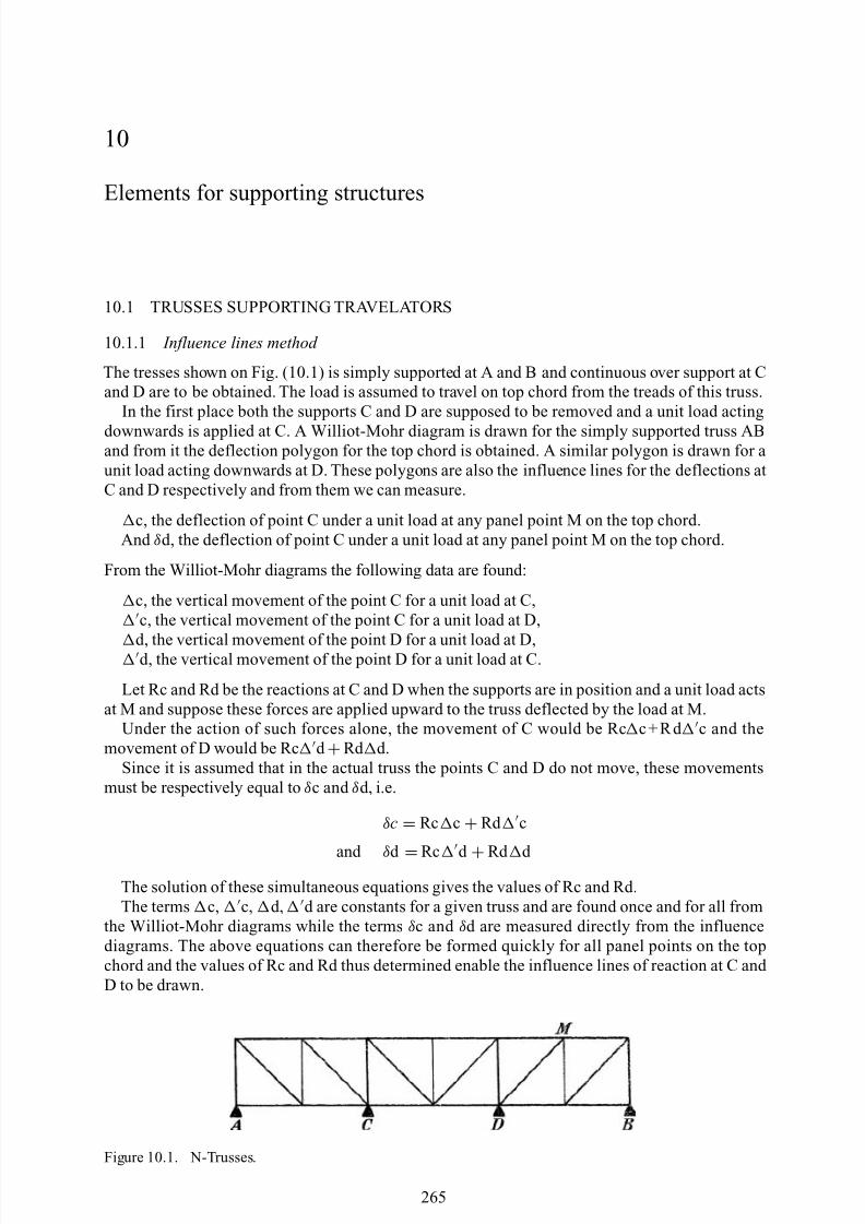
8/10/2019 Lifts Elevators Escalators and Moving Walkways Travelators 2DE2
http://slidepdf.com/reader/full/lifts-elevators-escalators-and-moving-walkways-travelators-2de2 76/169
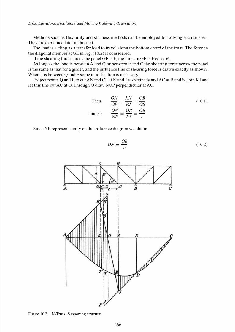
8/10/2019 Lifts Elevators Escalators and Moving Walkways Travelators 2DE2
http://slidepdf.com/reader/full/lifts-elevators-escalators-and-moving-walkways-travelators-2de2 77/169
Lifts, Elevators, Escalators and Moving Walkways/Travelators
Methods such as flexibility and stiffness methods can be employed for solving such trusses.They are explained later in this text.
The load is a cling as a transfer load to travel along the bottom chord of the truss. The force inthe diagonal member at GE in Fig. (10.2) is considered.
If the shearing force across the panel GE is F, the force in GE is F cosec θ .As long as the load is between A and Q or between E and C the shearing force across the panel
is the same as that for a girder, and the influence line of shearing force is drawn exactly as shown.When it is between Q and E some modification is necessary.
Project points Q and E to cut AN and CP at K and J respectively and AC at R and S. Join KJ and let this line cut AC at O. Through O draw NOP perpendicular at AC.
ThenON OP =
KN PJ =
OROS
(10.1)
and soON
NP = OR
RS = OR
c
Since NP represents unity on the influence diagram we obtain
ON = OR
c(10.2)
Figure 10.2. N-Truss: Supporting structure.
266
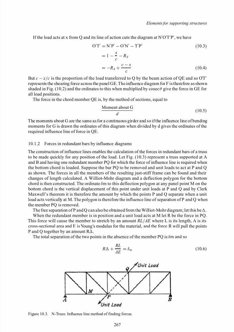
8/10/2019 Lifts Elevators Escalators and Moving Walkways Travelators 2DE2
http://slidepdf.com/reader/full/lifts-elevators-escalators-and-moving-walkways-travelators-2de2 78/169
Elements for supporting structures
If the load acts at x from Q and its line of action cuts the diagram at N O T P , we have
O T = N P − O N − T P (10.3)
= 1
− x
c − R
A
= − R A + c − x
c(10.4)
But c − x/ c is the proportion of the load transferred to Q by the beam action of QE and so O Trepresents the shearing force across the panel GE. The influence diagram for F is therefore as shownshaded in Fig. (10.2) and the ordinates to this when multiplied by cosec θ give the force in GE for all load positions.
The force in the chord member QE is, by the method of sections, equal to
Moment about Gd
(10.5)
The moments about G are the same as for a continuous girder and so if the influence line of bendingmoments for G is drawn the ordinates of this diagram when divided by d gives the ordinates of therequired influence line of force in QE.
10.1.2 Forces in redundant bars by influence diagrams
The construction of influence lines enables the calculation of the forces in redundant bars of a trussto be made quickly for any position of the load. Let Fig. (10.3) represent a truss supported at Aand B and having one redundant member PQ for which the force of influence line is required whenthe bottom chord is loaded. Suppose the bar PQ to be removed and unit loads to act at P and Q
as shown. The forces in all the members of the resulting just-stiff frame can be found and their changes of length calculated. A Williot-Mohr diagram and a deflection polygon for the bottomchord is then constructed. The ordinate δm to this deflection polygon at any panel point M on the bottom chord is the vertical displacement of this point under unit loads at P and Q and by Clerk Maxwell’s theorem it is therefore the amount by which the points P and Q separate when a unitload acts vertically at M. The polygon is therefore the influence line of separation of P and Q whenthe member PQ is removed.
The free separation of P and Q can also be obtained from the Williot-Mohr diagram; let this be .When the redundant member is in position and a unit load acts at M let R be the force in PQ.
This force will cause the member to stretch by an amount RL/ AE where L is its length, A is itscross-sectional area and E is Young’s modulus for the material, and the force R will pull the points
P and Q together by an amount R .The total separation of the two points in the absence of the member PQ is δm and so
R + RL AE = δm (10.6)
Figure 10.3. N-Truss: Influence line method of finding forces.
267
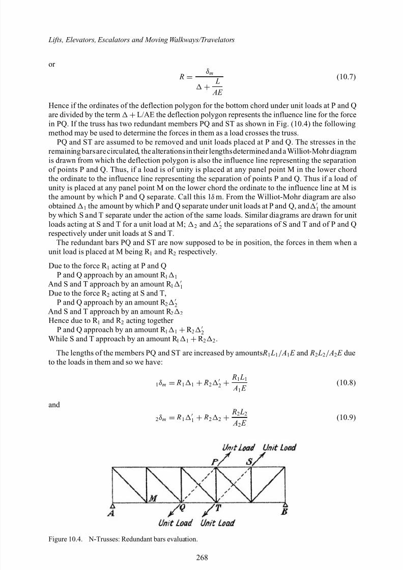
8/10/2019 Lifts Elevators Escalators and Moving Walkways Travelators 2DE2
http://slidepdf.com/reader/full/lifts-elevators-escalators-and-moving-walkways-travelators-2de2 79/169
Lifts, Elevators, Escalators and Moving Walkways/Travelators
or
R = δm
+ L AE
(10.7)
Hence if the ordinates of the deflection polygon for the bottom chord under unit loads at P and Qare divided by the term +L/AE the deflection polygon represents the influence line for the forcein PQ. If the truss has two redundant members PQ and ST as shown in Fig. (10.4) the followingmethod may be used to determine the forces in them as a load crosses the truss.
PQ and ST are assumed to be removed and unit loads placed at P and Q. The stresses in theremaining barsarecirculated, thealterationsin their lengthsdeterminedand a Williot-Mohr diagramis drawn from which the deflection polygon is also the influence line representing the separationof points P and Q. Thus, if a load is of unity is placed at any panel point M in the lower chord the ordinate to the influence line representing the separation of points P and Q. Thus if a load of unity is placed at any panel point M on the lower chord the ordinate to the influence line at M is
the amount by which P and Q separate. Call this 1 δ m. From the Williot-Mohr diagram are alsoobtained 1 the amount by which P and Q separate under unit loads at P and Q, and 1 the amount by which S and T separate under the action of the same loads. Similar diagrams are drawn for unitloads acting at S and T for a unit load at M; 2 and 2 the separations of S and T and of P and Qrespectively under unit loads at S and T.
The redundant bars PQ and ST are now supposed to be in position, the forces in them when aunit load is placed at M being R 1 and R 2 respectively.
Due to the force R 1 acting at P and QP and Q approach by an amount R 1 1
And S and T approach by an amount R 1 1Due to the force R 2 acting at S and T,
P and Q approach by an amount R 2 2And S and T approach by an amount R 2 2
Hence due to R 1 and R 2 acting together P and Q approach by an amount R 1 1 +R 2 2
While S and T approach by an amount R 1 1 +R 2 2 .
The lengths of the members PQ and ST are increased by amounts R1 L1 / A1 E and R2 L2 / A2 E dueto the loads in them and so we have:
1δm = R1 1 + R2 2 + R1 L1
A1 E (10.8)
and
2δm = R1 1 + R2 2 + R2 L2
A2 E (10.9)
Figure 10.4. N-Trusses: Redundant bars evaluation.
268
8/10/2019 Lifts Elevators Escalators and Moving Walkways Travelators 2DE2
http://slidepdf.com/reader/full/lifts-elevators-escalators-and-moving-walkways-travelators-2de2 80/169
Elements for supporting structures
These simultaneous equations enable the values of R 1 and R 2 to be found. It will be noticed that 1
and 1 and 2 and 2 are constant values for the frame whatever the position of the load on the bottom chord, while 1δm and 2δm are found from the respective deflection polygons. By this method therefore the forces in the two redundant members for any position of the load can be calculated by the solution of two simple simultaneous equations once the influence lines have been drawn.
10.1.3 Maximum bending moments and shear forces
The exact calculation of the maximum bending moments and shearing forces at all sections of atravelator as a train of loads passes across it is very laborious and the uncertainties introduced by the dynamic effects of the system travelling at high speed are such that extreme accuracy incalculation is not justified. It is usual therefore in design to adopt conventional systems of load tosimplify the procedure.
One method assumes that the effect of a train of rollers can be reproduced by an equivalentuniformly distributed load. It has already been shown that when a single load traverses a girder thecurve of maximum bending moments is a parabola having a maximum ordinate WL/4 at the centreof the span: if the concentrated load be supposed to be replaced by a uniformly distributed load of intensity w it is necessary, if the maximum bending moments are to be the same, to make:
wL2
8 = WL
4(10.10)
i.e. w = 2W
L
The bending moments at all the points when this equivalent load w covers the span will be thesame as those under the concentrated load W as it traverses the travelators. The maximum shearingforces caused by both will also be the same at the ends of the beam but for no other points, sincein the case of the concentrated load the curves of maximum shearing force are straight lines whilstin the case of the uniformly distributed load they are parabolas.
When the train consists of a number of concentrated loads under rollers, the curve of maximum bending moments can be enveloped by a curve which approximates to a parabola but which is rather flatter at midspan and steeper at the ends than a true parabola. It is thus impossible to obtain exactagreement at all points when a uniformly distributed load is substituted for a train. If a parabola isdrawn which has the same area as the true curve, the ordinates of the true curves are equal at aboutthe quarter point of the span and one approximate method of determining the effect of a train of loads is to calculate the maximum ending moment they produce at the quarter point and to make theequivalent uniformly distributed load of such magnitude that it gives the same value at that point.
The bending moment at the quarter-point of the span under a uniformly distributed load of intensity w is 3wL2 / 32 and if the calculated maximum bending moment at the same point due tothe actual load system is M the equivalent load is:
w = 32 M
3 L2 (10.11)
This equivalent load gives a bending moment at the centre of the span rather greater and near theend rather less than the correct values. Agreement between the true bending moment and that dueto a uniformly distributed load may be obtained for any point other than the quarter span by usinga different value of w and if a number of travelators or passenger walks have to be designed for thesame rolling load system it is worthwhile to determine the values of w appropriate to a number of points along the span. Once tables or curves embodying these data have been obtained they can beapplied very simply to the design of any travelators or passenger walks subjected to the particular load system, but unless the number to be designed is considerable the time involved in obtainingthe data will not be justified.
269
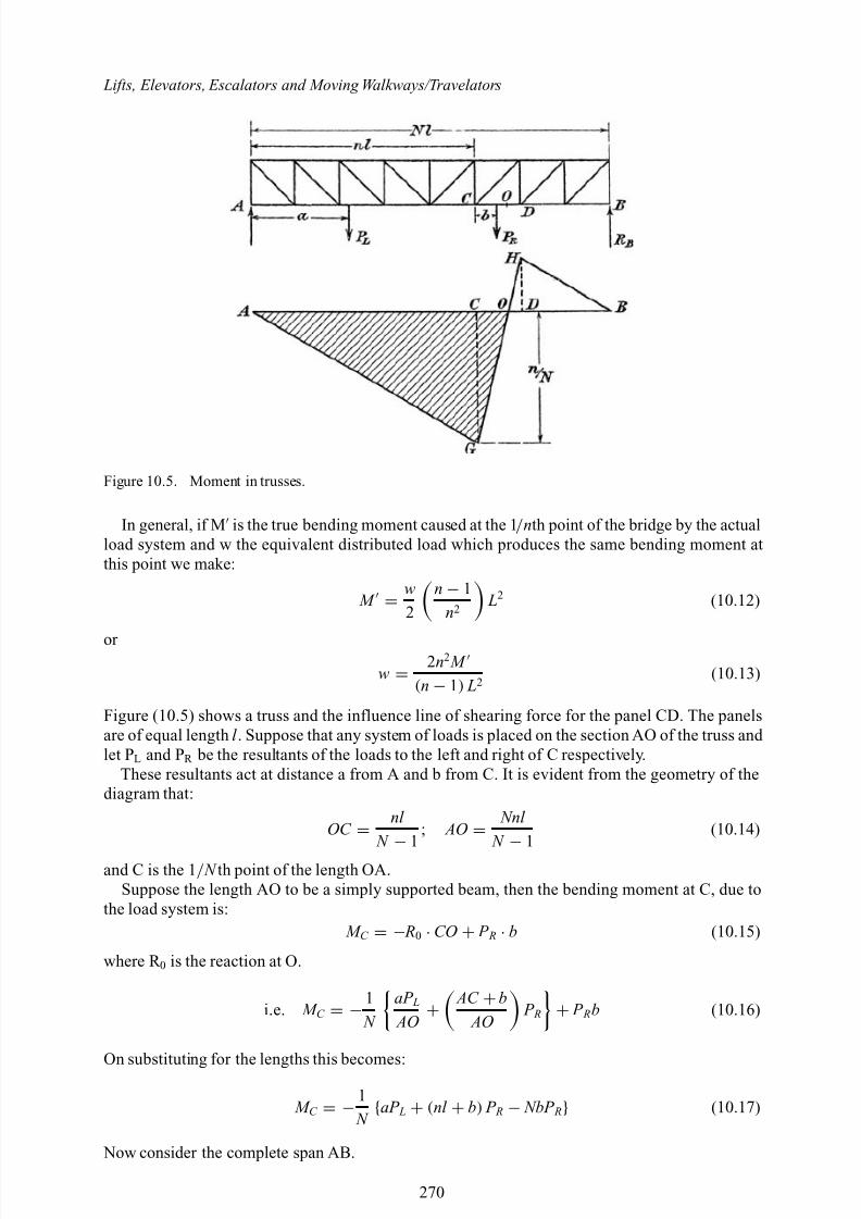
8/10/2019 Lifts Elevators Escalators and Moving Walkways Travelators 2DE2
http://slidepdf.com/reader/full/lifts-elevators-escalators-and-moving-walkways-travelators-2de2 81/169
Lifts, Elevators, Escalators and Moving Walkways/Travelators
Figure 10.5. Moment in trusses.
In general, if M is the true bending moment caused at the 1 / nth point of the bridge by the actualload system and w the equivalent distributed load which produces the same bending moment atthis point we make:
M = w2
n − 1n2
L2 (10.12)
or
w = 2n2 M (n − 1) L2
(10.13)
Figure (10.5) shows a truss and the influence line of shearing force for the panel CD. The panelsare of equal length l . Suppose that any system of loads is placed on the section AO of the truss and let PL and PR be the resultants of the loads to the left and right of C respectively.
These resultants act at distance a from A and b from C. It is evident from the geometry of thediagram that:
OC = nl
N
− 1
; AO = Nnl N
− 1
(10.14)
and C is the 1 / N th point of the length OA.Suppose the length AO to be a simply supported beam, then the bending moment at C, due to
the load system is: M C = − R0 · CO + P R · b (10.15)
where R 0 is the reaction at O.
i.e. M C = − 1 N
aP L AO +
AC + b AO
P R + P Rb (10.16)
On substituting for the lengths this becomes:
M C = − 1 N {aP L + (nl + b) P R − NbP R} (10.17)
Now consider the complete span AB.
270
8/10/2019 Lifts Elevators Escalators and Moving Walkways Travelators 2DE2
http://slidepdf.com/reader/full/lifts-elevators-escalators-and-moving-walkways-travelators-2de2 82/169
Elements for supporting structures
The shearing force across the panel CD is:
S CD = R B − bl P R (10.18)
which gives on substitution for R B ,
S CD = 1 Nl {aP L + (nl + b) P R − NbP R}, (10.19)
i.e. for any system of loads on AO,
M C = lS CD numerically (10.20)
Now let w s be the uniformly distributed load which will give the same maximum shearing forceacross the panel CD as the actual load system considered. This will occur when the length AO iscovered and then,
S CD = w s(area AOG) (10.21)
= w s × n N ×
Nnl 2( N − 1)
or
S CD = w sn2 l 2( N − 1)
(10.22)
Hence the true bending moment at C on a span of length AO is, from Eq. (10.20),
M C = w sn2 l 2
2( N − 1)(10.23)
Now the influence line of bending moments for point C on the span AO is a triangle similar toAOG, the ordinate CG being given by AC · CO / AO i.e. by nl / N .
From the tables or curves of equivalent loading already prepared we determine the value appro- priate to the 1 / N th point on a span of length AO. If this is w, the correct bending moment at C is,from the influence line,
w2 × AO ×
nl N
or M C =
wn2 l 2
2 ( N − 1)
Equating this to the value given in Eq. (10.23) we obtain,
w s = w (10.24)
Hence to determine the true value of the shearing force across the panel CD, we assumeAO to carrythe uniform load which produces the correct bending moment at the 1 / N th point on a span AO.
10.1.4 Flexibility method of analysisThe structure is made to statically determinate specifications. Calculate statical moments, shearsand axial effects etc. Remove the loads on the travelator deck and apply indeterminate reactionsone by one and draw flexibility diagrams. The final diagrams are drawn by algebraically addingall quantities along the ordinates of indeterminacy or other specified locations. The determinate
271
8/10/2019 Lifts Elevators Escalators and Moving Walkways Travelators 2DE2
http://slidepdf.com/reader/full/lifts-elevators-escalators-and-moving-walkways-travelators-2de2 83/169
Lifts, Elevators, Escalators and Moving Walkways/Travelators
moment, for example is M 0 and various other indeterminates are X 1 , X 2 , X 3…. X n . The finalmoment is:
M = M 0 + M 1 X 1 + M 2 X 2 + . . ... M n X n (10.25)
where M 1 to M
n are moments from the redundant reactions that are similar for axial effects:
N = N 0 + N 1 X 1 + N 2 X 2 + . . .. N n X n (10.26)
Other effects such as shear torsion can be represented in the same way. All are algebraically added in the form:
f ik = s M t M k
ds EI
bending
+ s N i N k
ds EA
direct force
+ λ s
V iV k dsGA
shear
+ s
M ti M tk dsGI t
torsion
(10.27)
where it has a variable section.The component of the travelator is divided into several points and moment I is integrated within
the established points:
for bending d s I = I C I ds
for direct force d s II = I C A ds
for shear force d s III = EI C GA ds
for torsional moment d s IV = EI C GI t
(10.28)
A Simpson rule is adopted for the integration process:
area under curve = L3 ( y1 + 4 y2 + y3) (10.29)
Where y1 , y2 , y3 are the ordinates between two equal spaces L. The product integral can be easilyobtained by using Table 10.1. This will ease the job of evaluating various moments and forces. Theflexibility matrix for n indeterminacies is given as:
f 11 f 12 · · · f 1n
f 21 f 22 · · · f 2n...
......
f n1 f n2
· · · f nn
X 1 X 2
... X n
= − D10
D20...
Dn0
(10.30)
[ f ] × { X } = −{ D} (10.31)
The Ds are displacements for statically determinate assumed structure and X s are indeterminatequantities obtained by matrix [ f ]. In the analysis a choice is given either to find moments first or reactions f irst. All other quantities are determined subsequently.
Table 10.1 gives flexibility coefficients for solving such problems.
Application to deflection of trussesAn expression for the principle of virtual work as applied specifically to trusses. Consider firstthe case of an ideal pin-jointed truss where both the deforming P loads and the virtual Q loads areapplied only at the joints of the truss. In such a case, the individual members will be subjected onlyto axial member forces F P with no shear or bending moment involved. Furthermore, the member force F Q will be constant throughout the length L of a given member, and since:
L
0eods = axial change in length of member = L (10.32)
272
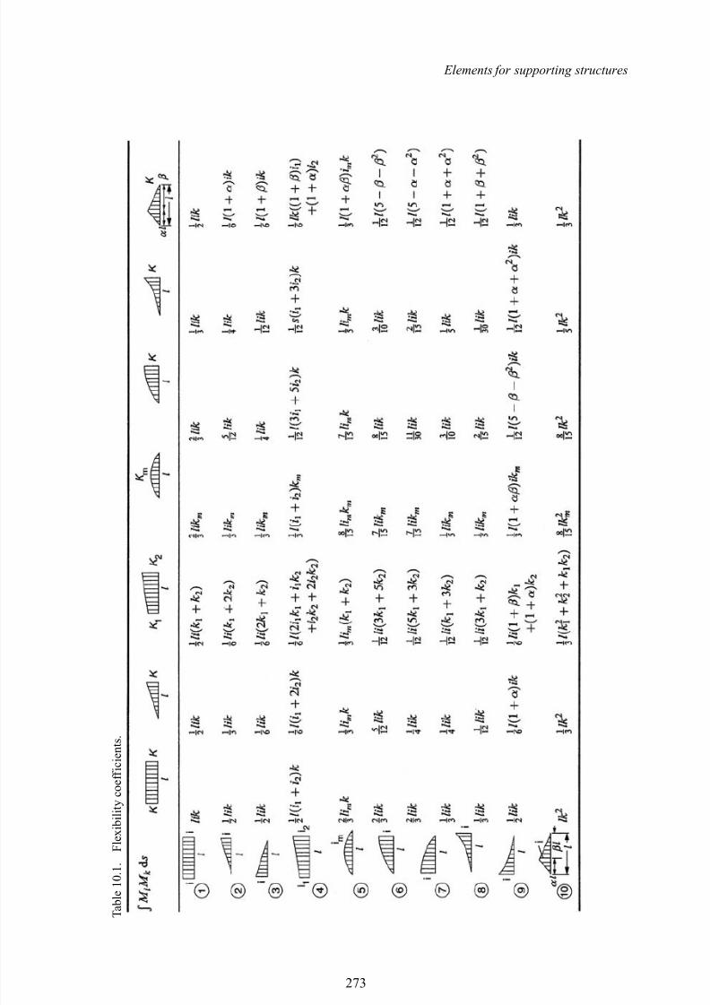
8/10/2019 Lifts Elevators Escalators and Moving Walkways Travelators 2DE2
http://slidepdf.com/reader/full/lifts-elevators-escalators-and-moving-walkways-travelators-2de2 84/169
Elements for supporting structures
T a b l e 1 0 . 1 .
F l e x i b i l i t y c o e f f i c i e n t s .
273
8/10/2019 Lifts Elevators Escalators and Moving Walkways Travelators 2DE2
http://slidepdf.com/reader/full/lifts-elevators-escalators-and-moving-walkways-travelators-2de2 85/169
Lifts, Elevators, Escalators and Moving Walkways/Travelators
where,e0 =axial strains due to P or Q loads and temperature change t. F P and F Q axial forces due to P or Q.In a similar fashion, the following third and fourth terms could be added by giving the contri-
butions of the deformations due to the bending shears Sp and twisting moments T P to the total:
C s = L
0
V Q V P
AG d s +
L
0
T Q T P
K T G d s (10.33)
where,V Q , T Q =shear and twisting moment on section m-m due to Q loads;Cs =shape factor varying with shape of cross section; K t =torsional constant for cross section (equals polar moment of inertia for circular
cross section); and G =shear modulus of material in addition to the notation introduced previously.
The virtual work of deformation for one particular truss member becomes:
W d = F Q L
0e0ds = F Q L (10.34)
When such products for all the members of the truss are summed, the internal virtual work of deformation for the entire truss may be represented as:
W d = F Q L (10.35)
and therefore the principle of virtual work as applied to an ideal pin-jointed truss becomes:
Qδ = F Q L (10.36)
Suitable expressions for L can easily be developed, depending on whether the imposed changein length is produced by the P loads, by a change in temperature, or by some other cause. For a prismatic member having a constant cross-sectional area A s and a constant modulus of elasticity E ,if the deformation is due to joint loads P on the truss, then
L = F P L A s E
(10.37)
if the deformation is due to a uniform change in temperature t , then
L = α t tL (10.38)and if the deformation is caused by both these effects acting simultaneously, then
L = F P L A s E + α t tL (10.39)
Equation (10.36) is the basis for the method of virtual work for computing the deflection of ideal pin-jointed trusses. Suppose, for example, that we wish to compute the vertical component of thedeflection of joint c caused by the P loads. Suppose that we select as the virtual Q-load system aunit vertical load at joint c together with its reactions. If we imagine that we first apply this systemto the structure, then when we apply the actual deforming loads P, the Q loads will be given a rideand will do a certain amount of external virtual work. According to the principle of virtual work,the internal Q stresses will do an equal amount of internal virtual work as the members changelength owing to the Fp stresses. Applying Eq. (10.36) gives:
(1)( δc) + W R = F Q F P L A s E
(10.40)
274
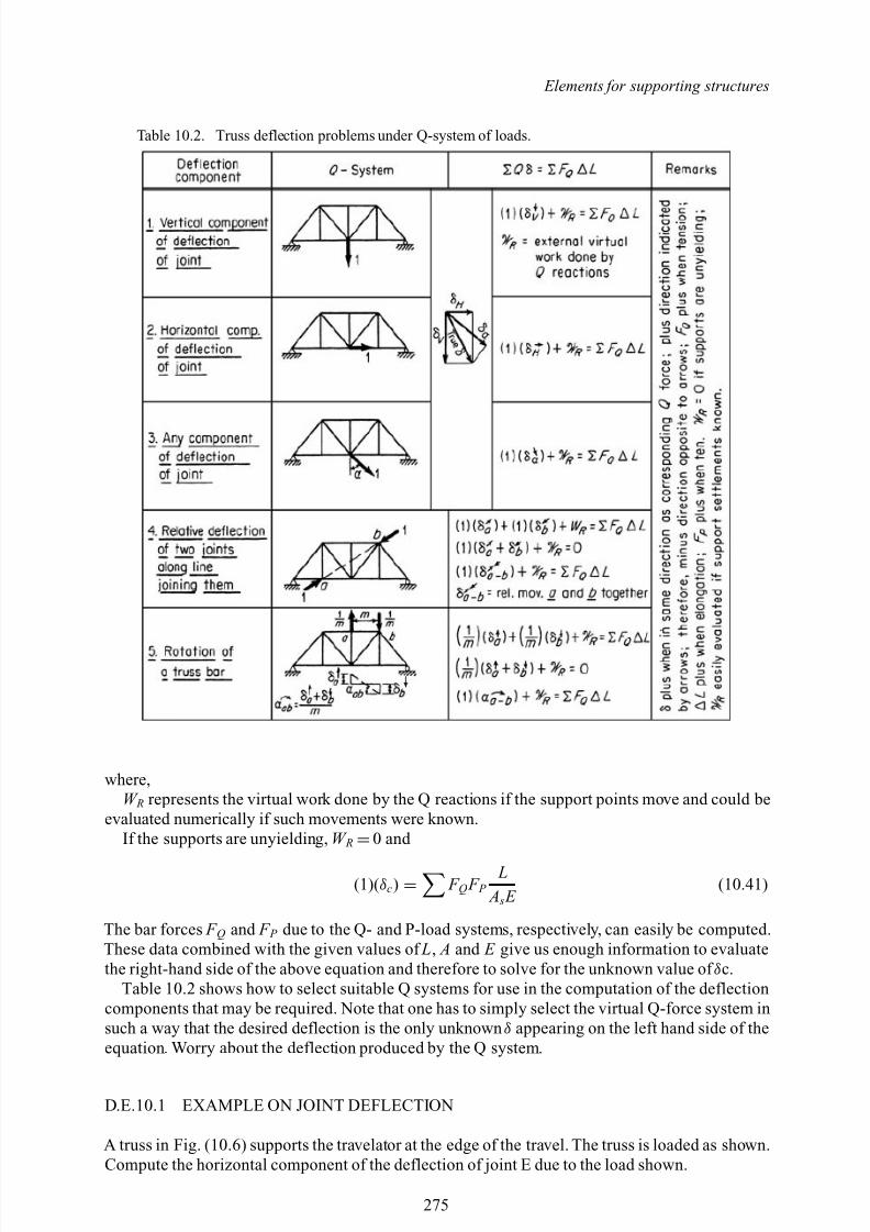
8/10/2019 Lifts Elevators Escalators and Moving Walkways Travelators 2DE2
http://slidepdf.com/reader/full/lifts-elevators-escalators-and-moving-walkways-travelators-2de2 86/169
Elements for supporting structures
Table 10.2. Truss deflection problems under Q-system of loads.
where,W R represents the virtual work done by the Q reactions if the support points move and could be
evaluated numerically if such movements were known.If the supports are unyielding, W R =0 and
(1)( δc) = F Q F P L
A s E (10.41)
The bar forces F Q and F P due to the Q- and P-load systems, respectively, can easily be computed.These data combined with the given values of L, A and E give us enough information to evaluatethe right-hand side of the above equation and therefore to solve for the unknown value of δc.
Table 10.2 shows how to select suitable Q systems for use in the computation of the deflectioncomponents that may be required. Note that one has to simply select the virtual Q-force system insuch a way that the desired deflection is the only unknown δ appearing on the left hand side of theequation. Worry about the deflection produced by the Q system.
D.E.10.1 EXAMPLE ON JOINT DEFLECTION
A truss in Fig. (10.6) supports the travelator at the edge of the travel. The truss is loaded as shown.Compute the horizontal component of the deflection of joint E due to the load shown.
275
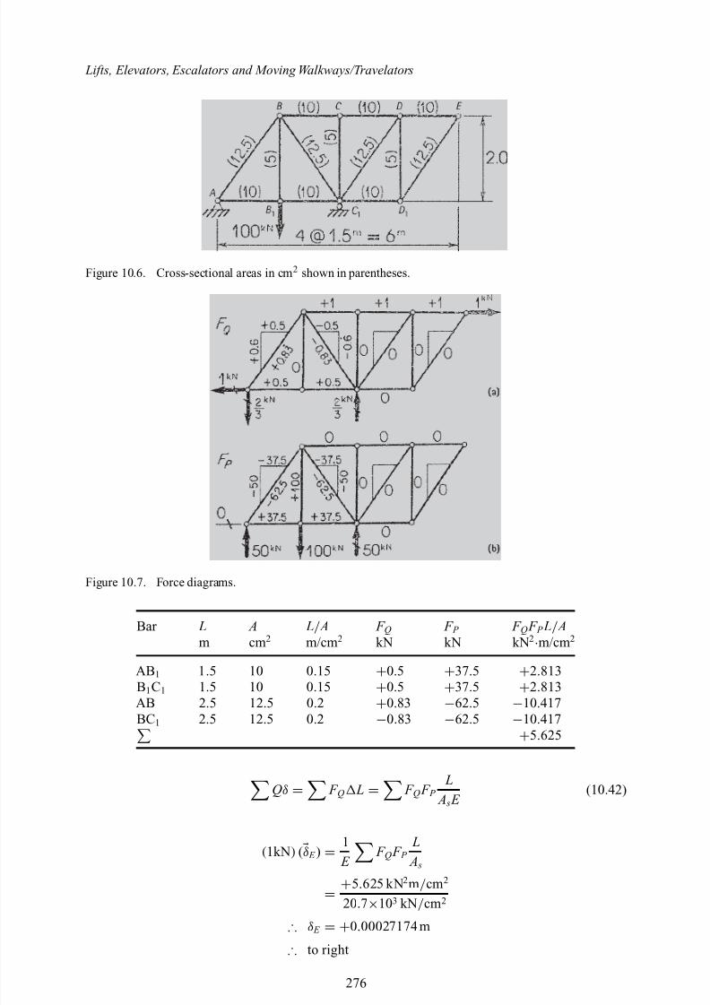
8/10/2019 Lifts Elevators Escalators and Moving Walkways Travelators 2DE2
http://slidepdf.com/reader/full/lifts-elevators-escalators-and-moving-walkways-travelators-2de2 87/169
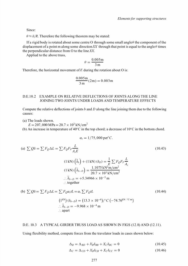
8/10/2019 Lifts Elevators Escalators and Moving Walkways Travelators 2DE2
http://slidepdf.com/reader/full/lifts-elevators-escalators-and-moving-walkways-travelators-2de2 88/169
Elements for supporting structures
Since:
θ ≈δ/ R. Therefore the following theorem may be stated:
If a rigid body is rotated about some centre O through some small angle θ the component of the
displacement of a point m along some direction XX through that point is equal to the angle θ timesthe perpendicular distance from O to the line XX .
Applied to the above truss,
θ = 0.005m
3 mTherefore, the horizontal movement of E during the rotation about O is:
0.005m3 m
(2m) = 0.003m
D.E.10.2 EXAMPLE ON RELATIVE DEFLECTIONS OF JOINTS ALONG THE LINEJOINING TWO JOINTS UNDER LOADS AND TEMPERATURE EFFECTS
Compute the relative deflections of joints b and D along the line joining them due to the followingcauses:
(a) The loads shown. E =207, 000 MPa =20 .7 ×103 kN / cm 2
(b) An increase in temperature of 40 ◦C in the top chord; a decrease of 10 ◦C in the bottom chord.
αt =
1/ 75,000 per ◦C .
(a) Qδ = F Q L = F Q F P L
A s E (10.43)
(1 kN ) δb + (1 kN ) ( δ D) = 1 E
F Q F P L A s
(1 kN ) ↔δb− D = 1.1075 kN 2m / cm 2
20 .7 × 103 kN / cm 2
∴↔δb− D = +5.34966 × 10⁻⁵ m
∴ together
(b) Qδ = F Q L= F Q α t tL =α t F Q tL (10.44)
1kN (δb− D) = 13 .3 × 10−6 / ◦C −74 .76kN ·◦C·m∴
↔δb− D = −9.968 × 10⁻⁴ m∴ apart
D.E. 10.3 A TYPICAL GIRDER TRUSS LOAD AS SHOWN IN FIGS (12.8) AND (12.11).
Using flexibility method, compute forces from the travelator loads in cases shown below:
B = BD + X Bδ BB + X C δ BC = 0 (10.45)
C = CD + X BδCB + X C δCC = 0 (10.46)
277
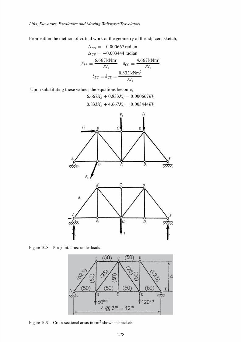
8/10/2019 Lifts Elevators Escalators and Moving Walkways Travelators 2DE2
http://slidepdf.com/reader/full/lifts-elevators-escalators-and-moving-walkways-travelators-2de2 89/169
Lifts, Elevators, Escalators and Moving Walkways/Travelators
From either the method of virtual work or the geometry of the adjacent sketch,
BD = −0.000667 radian
CD = −0.003444 radian
δ BB = 6.667kNm 2
EI 1δCC = 4.667kNm 2
EI 1
δ BC = δCB = 0.833 kNm 2
EI 1
Upon substituting these values, the equations become,6.667 X B + 0.833 X C = 0.000667 EI 1
0.833 X B + 4.667 X C = 0.003444 EI 1
Figure 10.8. Pin-joint. Truss under loads.
Figure 10.9. Cross-sectional areas in cm 2 shown in brackets.
278
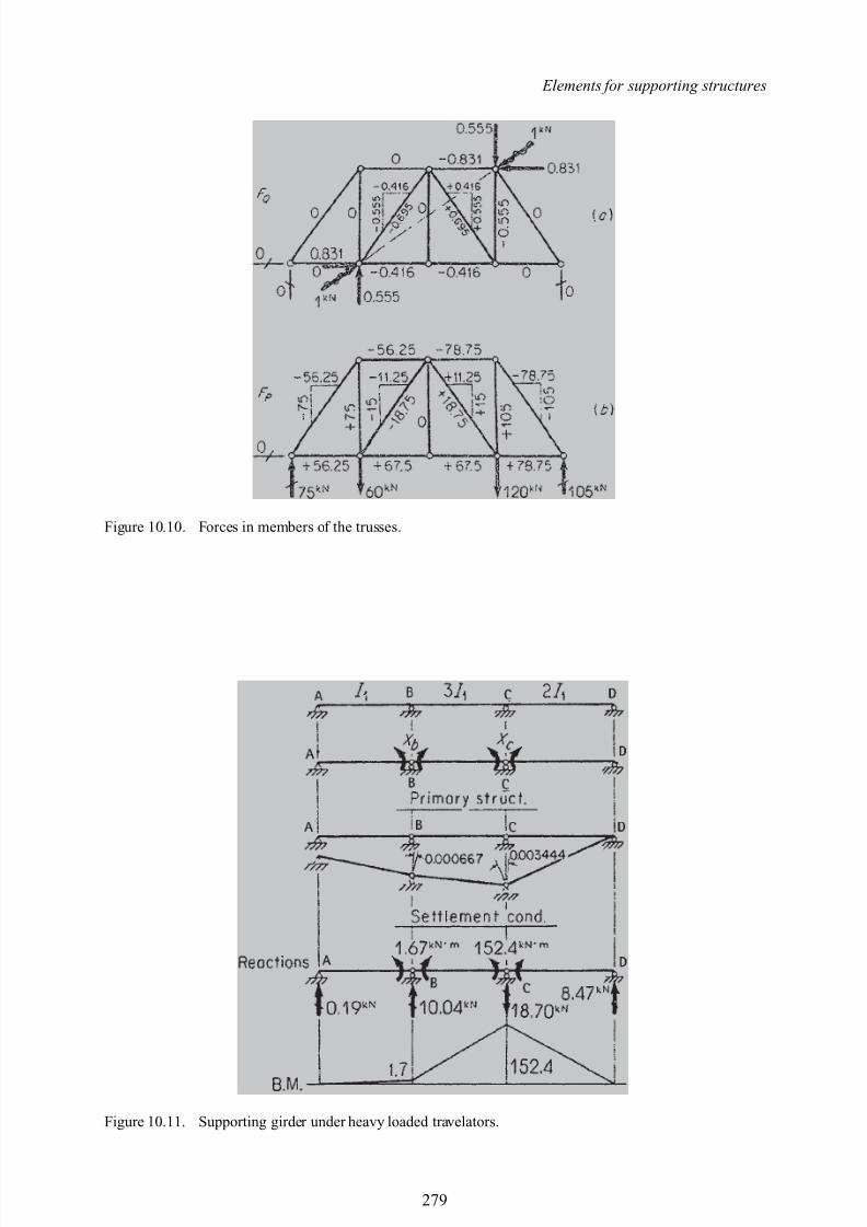
8/10/2019 Lifts Elevators Escalators and Moving Walkways Travelators 2DE2
http://slidepdf.com/reader/full/lifts-elevators-escalators-and-moving-walkways-travelators-2de2 90/169
Elements for supporting structures
Figure 10.10. Forces in members of the trusses.
Figure 10.11. Supporting girder under heavy loaded travelators.
279
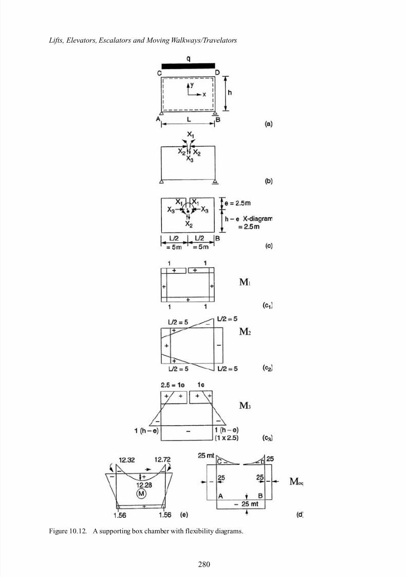
8/10/2019 Lifts Elevators Escalators and Moving Walkways Travelators 2DE2
http://slidepdf.com/reader/full/lifts-elevators-escalators-and-moving-walkways-travelators-2de2 91/169
Lifts, Elevators, Escalators and Moving Walkways/Travelators
Figure 10.12. A supporting box chamber with flexibility diagrams.
280
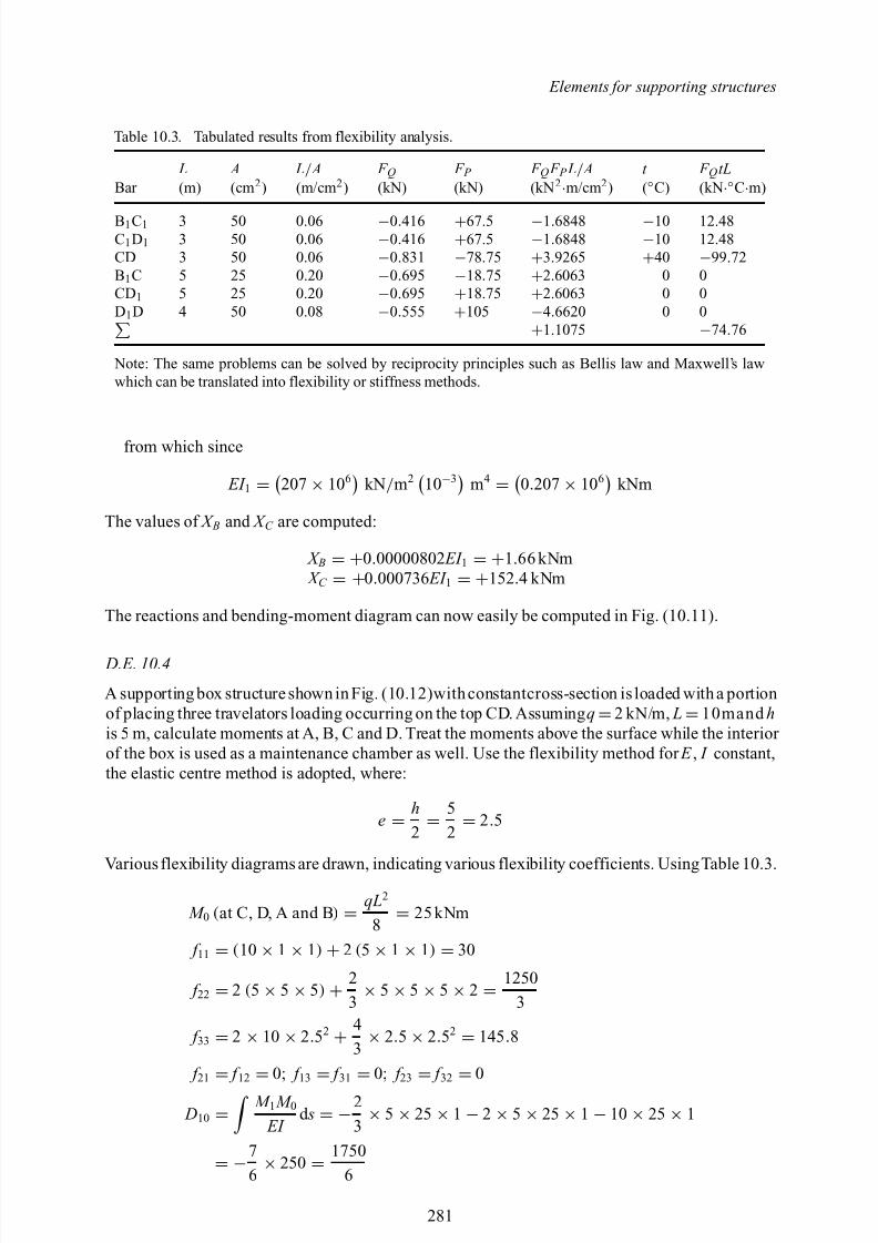
8/10/2019 Lifts Elevators Escalators and Moving Walkways Travelators 2DE2
http://slidepdf.com/reader/full/lifts-elevators-escalators-and-moving-walkways-travelators-2de2 92/169
Elements for supporting structures
Table 10.3. Tabulated results from flexibility analysis.
L A L/ A F Q F P F Q F P L/ A t F Q tLBar (m) (cm 2 ) (m/cm 2 ) (kN) (kN) (kN 2·m/cm 2 ) (◦C) (kN ·◦C·m)
B1C1 3 50 0.06 −0.416 +67.5 −1.6848 −10 12.48C1D1 3 50 0.06 −0.416 +67.5 −1.6848 −10 12.48CD 3 50 0.06 −0.831 −78 .75 +3.9265 +40 −99 .72B1C 5 25 0.20 −0.695 −18 .75 +2.6063 0 0CD 1 5 25 0.20 −0.695 +18.75 +2.6063 0 0D1D 4 50 0.08 −0.555 +105 −4.6620 0 0
+1.1075 −74 .76
Note: The same problems can be solved by reciprocity principles such as Bellis law and Maxwell’s lawwhich can be translated into flexibility or stiffness methods.
from which since
EI 1 = 207 × 106 kN / m2 10−3 m4 = 0.207 × 10⁶ kNm
The values of X B and X C are computed:
X B = +0.00000802 EI 1 = +1.66 kNm X C = +0.000736 EI 1 = +152 .4 kNm
The reactions and bending-moment diagram can now easily be computed in Fig. (10.11).
D.E. 10.4
A supporting box structure shown in Fig. (10.12)withconstantcross-section is loaded with a portionof placing three travelators loading occurring on the top CD. Assuming q =2 kN/m, L=10mand his 5 m, calculate moments at A, B, C and D. Treat the moments above the surface while the interior of the box is used as a maintenance chamber as well. Use the flexibility method for E , I constant,the elastic centre method is adopted, where:
e = h2 =
52 = 2.5
Various flexibility diagrams are drawn, indicating various flexibility coefficients. UsingTable 10.3.
M 0 (at C, D, A and B ) = qL2
8 = 25 kNm
f 11 = (10 × 1 × 1) + 2 (5 × 1 × 1) = 30
f 22 = 2 (5 × 5 × 5) + 23 × 5 × 5 × 5 × 2 =
12503
f 33 = 2 × 10 × 2.52 + 43 × 2.5 × 2.52 = 145 .8
f 21
= f 12
= 0; f 13
= f 31
= 0; f 23
= f 32
= 0
D10 = M 1 M 0 EI
d s = −23 × 5 × 25 × 1 − 2 × 5 × 25 × 1 − 10 × 25 × 1
= −76 × 250 =
17506
281
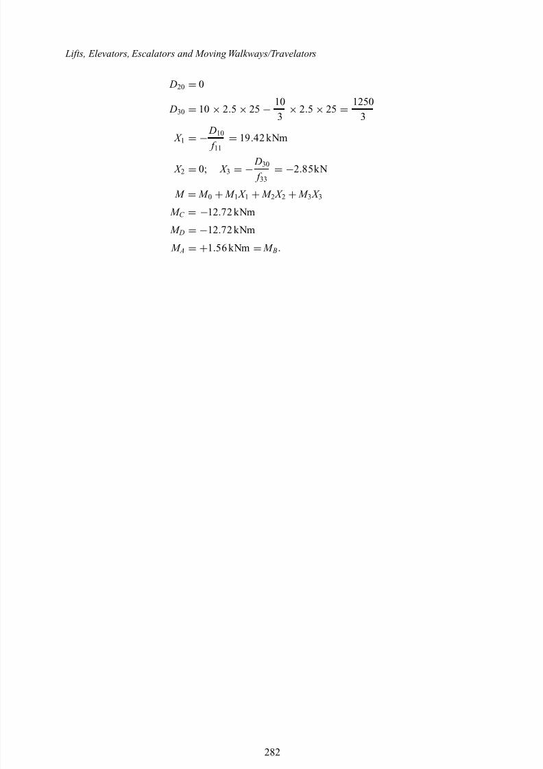
8/10/2019 Lifts Elevators Escalators and Moving Walkways Travelators 2DE2
http://slidepdf.com/reader/full/lifts-elevators-escalators-and-moving-walkways-travelators-2de2 93/169
Lifts, Elevators, Escalators and Moving Walkways/Travelators
D20 = 0
D30 = 10 × 2.5 × 25 − 10
3 × 2.5 × 25 = 1250
3
X 1 = − D10 f 11 = 19 .42 kNm
X 2 = 0; X 3 = − D30
f 33 = −2.85kN
M = M 0 + M 1 X 1 + M 2 X 2 + M 3 X 3
M C = −12 .72 kNm
M D = −12 .72 kNm
M A = +1.56 kNm = M B.
282

8/10/2019 Lifts Elevators Escalators and Moving Walkways Travelators 2DE2
http://slidepdf.com/reader/full/lifts-elevators-escalators-and-moving-walkways-travelators-2de2 94/169
Appendix I
Supporting Analyses and Computer Programsusing Finite Element

8/10/2019 Lifts Elevators Escalators and Moving Walkways Travelators 2DE2
http://slidepdf.com/reader/full/lifts-elevators-escalators-and-moving-walkways-travelators-2de2 95/169
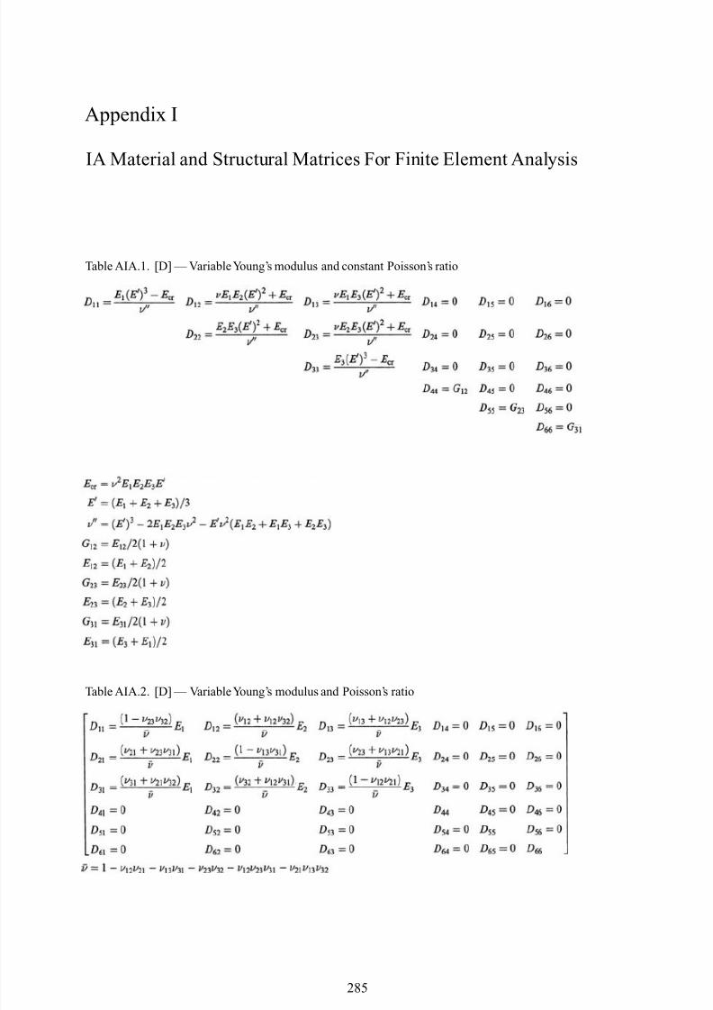
8/10/2019 Lifts Elevators Escalators and Moving Walkways Travelators 2DE2
http://slidepdf.com/reader/full/lifts-elevators-escalators-and-moving-walkways-travelators-2de2 96/169
Appendix I
IA Material and Structural Matrices For Finite Element Analysis
Table AIA.1. [D] — VariableYoung’s modulus and constant Poisson’s ratio
Table AIA.2. [D] — VariableYoung’s modulus and Poisson’s ratio
285
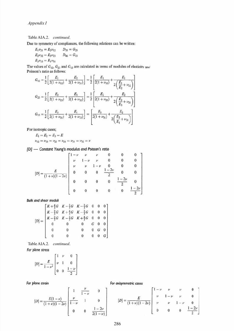
8/10/2019 Lifts Elevators Escalators and Moving Walkways Travelators 2DE2
http://slidepdf.com/reader/full/lifts-elevators-escalators-and-moving-walkways-travelators-2de2 97/169
Appendix I
Table AIA.2. continued .
Table AIA.2. continued .
286
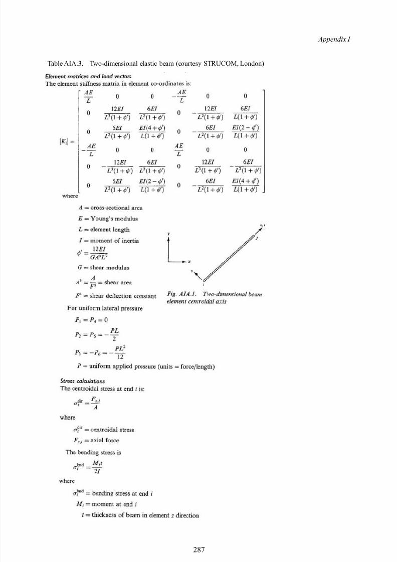
8/10/2019 Lifts Elevators Escalators and Moving Walkways Travelators 2DE2
http://slidepdf.com/reader/full/lifts-elevators-escalators-and-moving-walkways-travelators-2de2 98/169
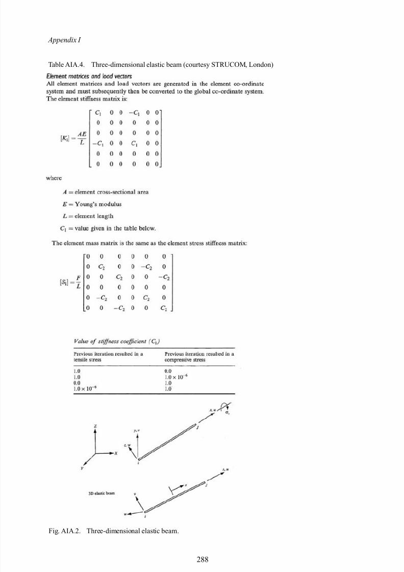
8/10/2019 Lifts Elevators Escalators and Moving Walkways Travelators 2DE2
http://slidepdf.com/reader/full/lifts-elevators-escalators-and-moving-walkways-travelators-2de2 99/169
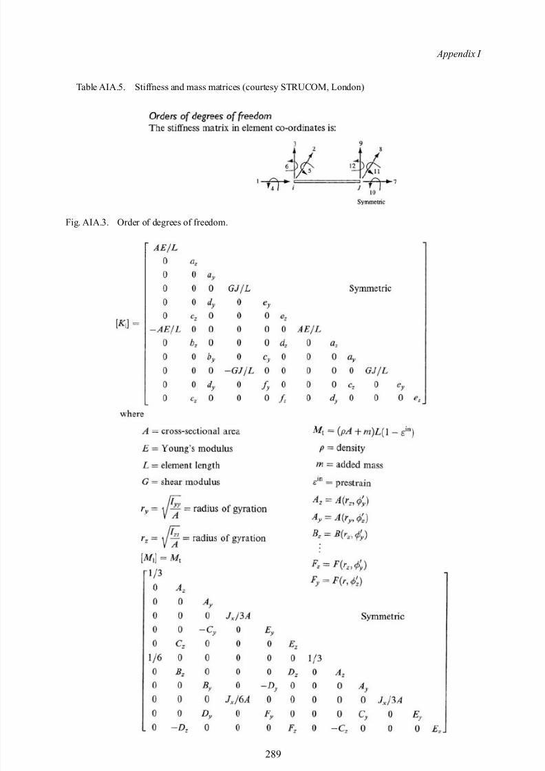
8/10/2019 Lifts Elevators Escalators and Moving Walkways Travelators 2DE2
http://slidepdf.com/reader/full/lifts-elevators-escalators-and-moving-walkways-travelators-2de2 100/169
Appendix I
Table AIA.5. Stiffness and mass matrices (courtesy STRUCOM, London)
Fig. AIA.3. Order of degrees of freedom.
289
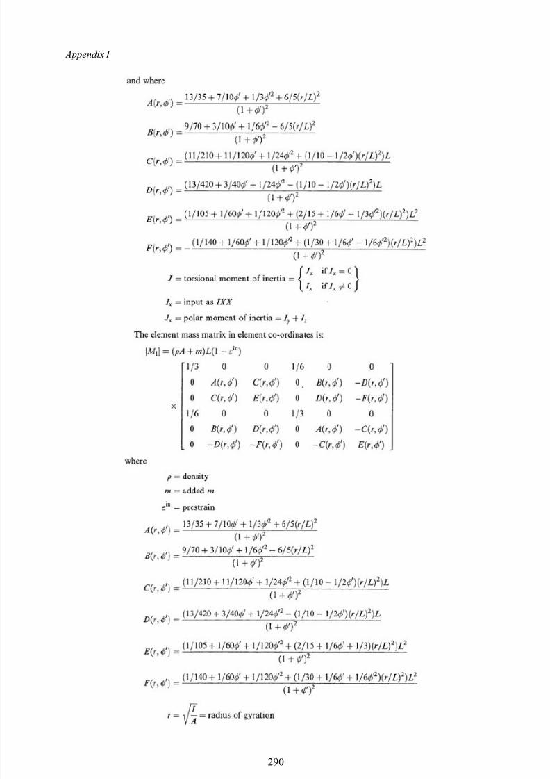
8/10/2019 Lifts Elevators Escalators and Moving Walkways Travelators 2DE2
http://slidepdf.com/reader/full/lifts-elevators-escalators-and-moving-walkways-travelators-2de2 101/169
Appendix I
290
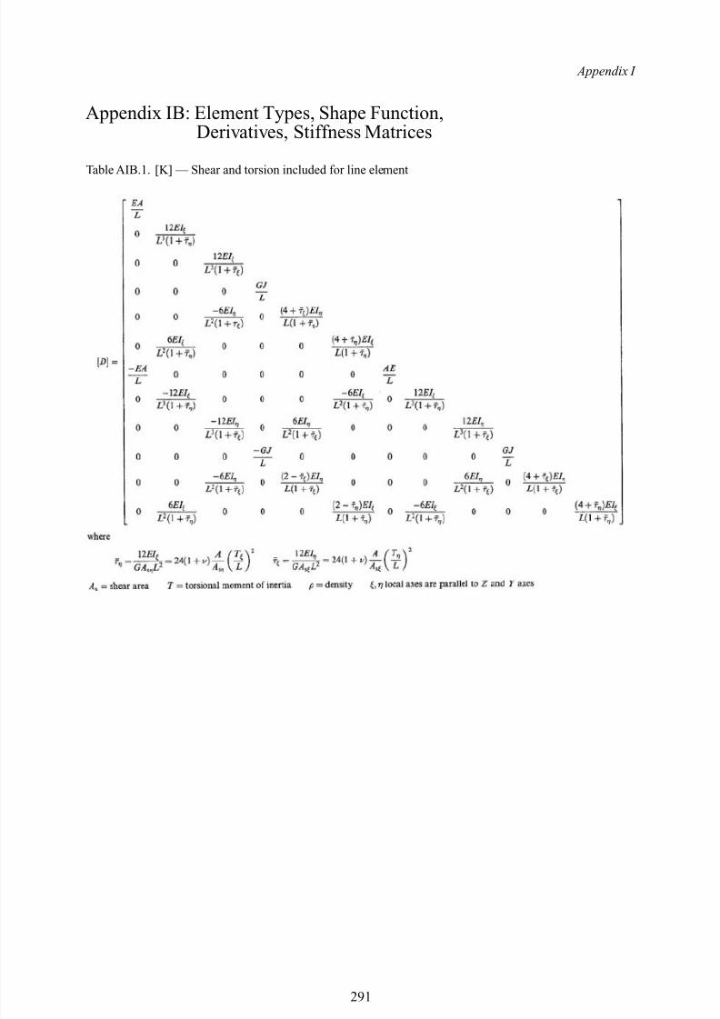
8/10/2019 Lifts Elevators Escalators and Moving Walkways Travelators 2DE2
http://slidepdf.com/reader/full/lifts-elevators-escalators-and-moving-walkways-travelators-2de2 102/169
Appendix I
Appendix IB: Element Types, Shape Function,Derivatives, Stiffness Matrices
Table AIB.1. [K] — Shear and torsion included for line element
291
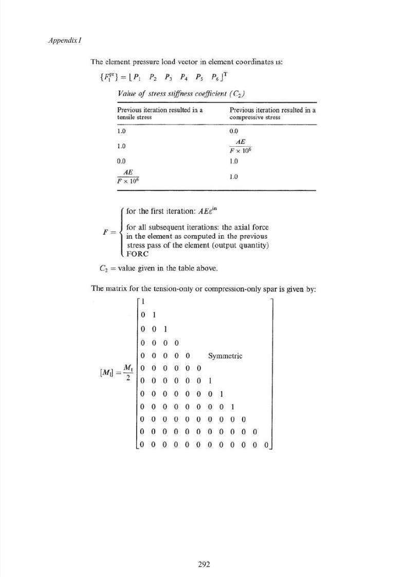
8/10/2019 Lifts Elevators Escalators and Moving Walkways Travelators 2DE2
http://slidepdf.com/reader/full/lifts-elevators-escalators-and-moving-walkways-travelators-2de2 103/169
Appendix I
292
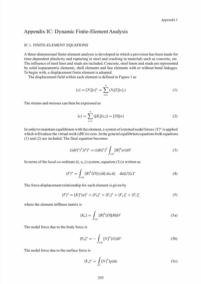
8/10/2019 Lifts Elevators Escalators and Moving Walkways Travelators 2DE2
http://slidepdf.com/reader/full/lifts-elevators-escalators-and-moving-walkways-travelators-2de2 104/169
Appendix I
Appendix IC: Dynamic Finite-Element Analysis
IC.1. FINITE-ELEMENT EQUATIONS
A three-dimensional finite-element analysis is developed in which a provision has been made for time-dependent plasticity and rupturing in steel and cracking in materials such as concrete, etc.The influence of steel liner and studs are included. Concrete, steel liners and studs are represented by solid isoparametric elements, shell elements and line elements with or without bond linkages.To begin with, a displacement finite element is adopted.
The displacement field within each element is defined in Figure 1 as
{ x} = [ N ]{ x}e =n
i=1
( N i[ I ]{ x}i) (1)
The strains and stresses can then be expressed as
{} =n
i=1
([ Bi]{ xi}) = [ D]{σ } (2)
In order to maintain equilibrium with the element, a system of external nodal forces {F} e is applied which will reduce the virtual work (dW) to zero. In the general equilibrium equations both equations(1) and (2) are included. The final equation becomes
({d δ}e)T{ F }e = ({d δ}e)T
vol[ B]T{σ }d V (3)
In terms of the local co-ordinate ( ξ , η, ζ ) system, equation (3) is written as
{ F }e = vol[ B]T[ D]{}d ξ.d η.d ζ det[ J ]{ x}c (4)
The force-displacement relationship for each element is given by
{ F
}e
= [ K ]c
{u
}e
+ { F b
}e
+ { F s
}e
+ { F σ
}ei
+ { F
}ec (5)
where the element stiffness matrix is
[ K c] = vol [ B]T[ D][ B]d V (5a)
The nodal force due to the body force is
{F b}e = − vol[ N ]T{G }d V (5b)
The nodal force due to the surface force is
{Fs}e = s[ N ]T{ p}d s (5c)
293
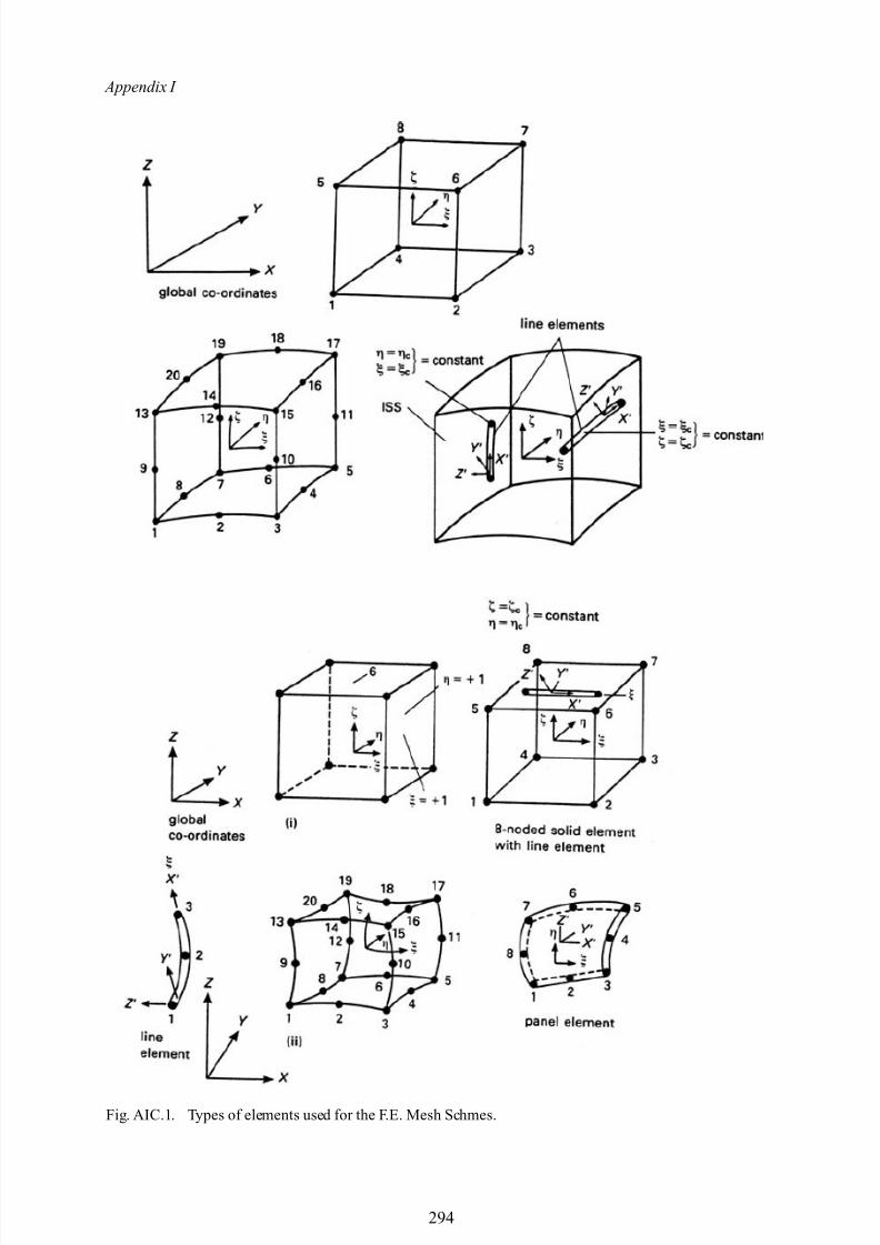
8/10/2019 Lifts Elevators Escalators and Moving Walkways Travelators 2DE2
http://slidepdf.com/reader/full/lifts-elevators-escalators-and-moving-walkways-travelators-2de2 105/169
Appendix I
Fig. AIC.1. Types of elements used for the F.E. Mesh Schmes.
294
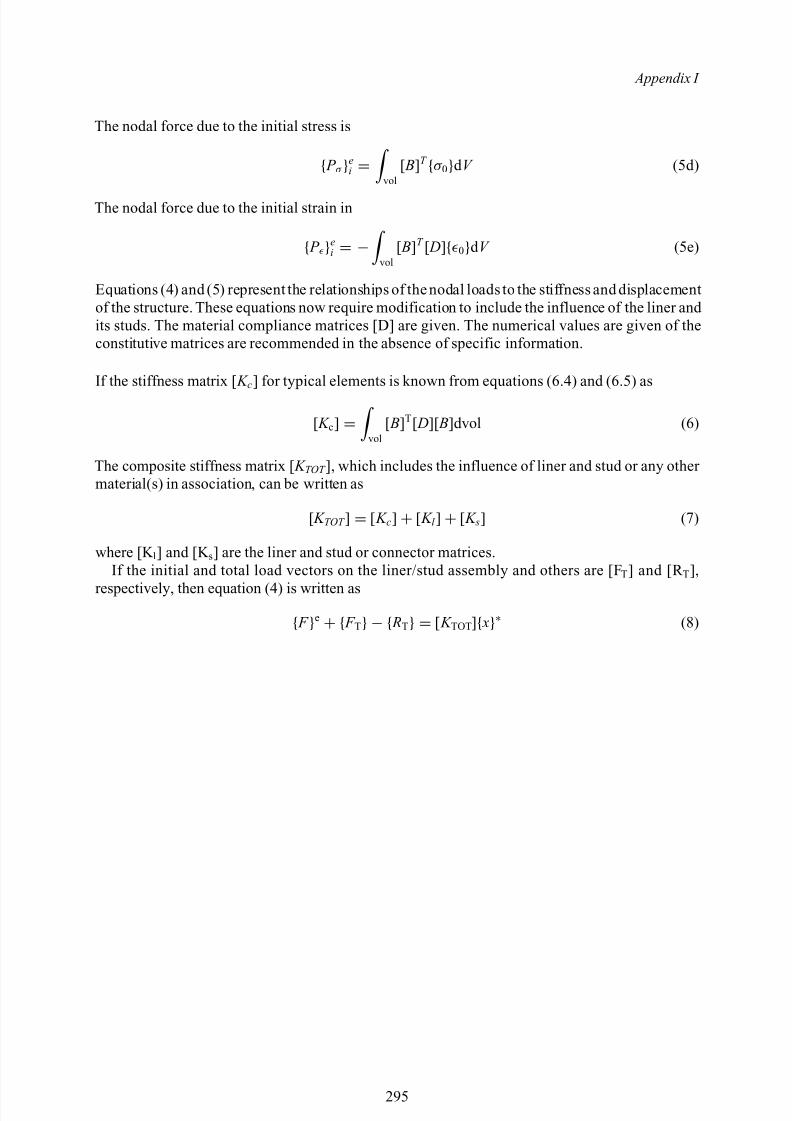
8/10/2019 Lifts Elevators Escalators and Moving Walkways Travelators 2DE2
http://slidepdf.com/reader/full/lifts-elevators-escalators-and-moving-walkways-travelators-2de2 106/169
Appendix I
The nodal force due to the initial stress is
{ P σ }ei = vol
[ B]T {σ 0}d V (5d)
The nodal force due to the initial strain in
{ P }ei = − vol
[ B]T [ D]{0}d V (5e)
Equations (4) and (5) represent the relationships of the nodal loads to the stiffness and displacementof the structure. These equations now require modification to include the influence of the liner and its studs. The material compliance matrices [D] are given. The numerical values are given of theconstitutive matrices are recommended in the absence of specific information.
If the stiffness matrix [ K c ] for typical elements is known from equations (6.4) and (6.5) as
[ K c] = vol[ B]T[ D][ B]dvol (6)
The composite stiffness matrix [ K TOT ], which includes the influence of liner and stud or any other material(s) in association, can be written as
[ K TOT ] = [ K c] + [ K l ] + [ K s] (7)
where [K l] and [K s] are the liner and stud or connector matrices.If the initial and total load vectors on the liner/stud assembly and others are [F T] and [R T],
respectively, then equation (4) is written as
{ F }e + { F T} − { RT} = [ K TOT ]{ x}∗ (8)
295
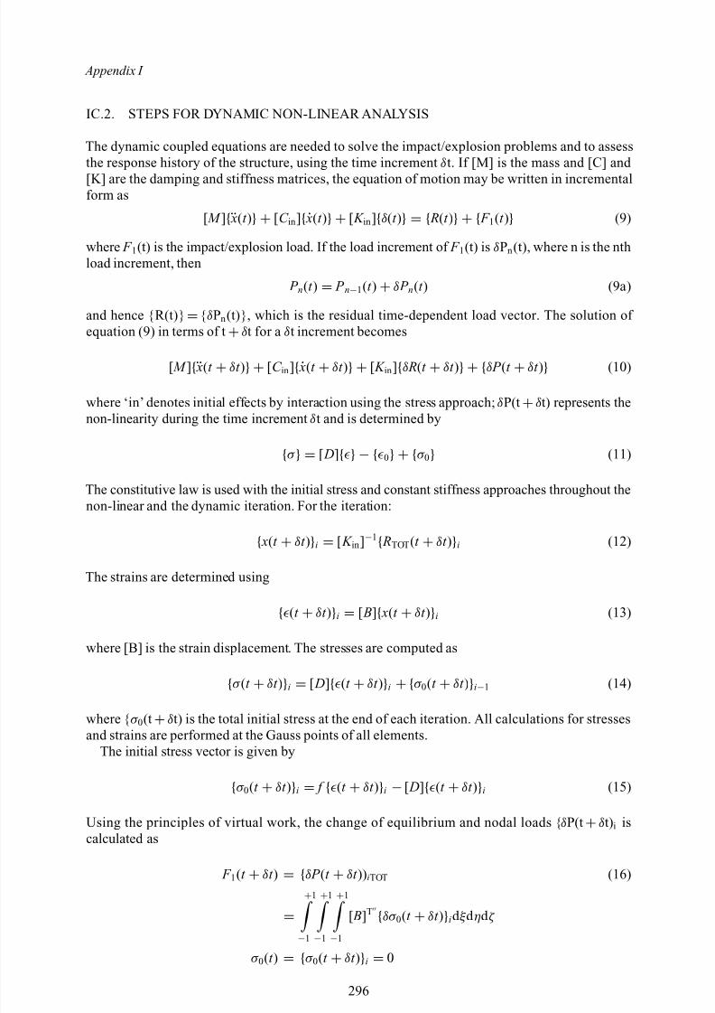
8/10/2019 Lifts Elevators Escalators and Moving Walkways Travelators 2DE2
http://slidepdf.com/reader/full/lifts-elevators-escalators-and-moving-walkways-travelators-2de2 107/169
Appendix I
IC.2. STEPS FOR DYNAMIC NON-LINEAR ANALYSIS
The dynamic coupled equations are needed to solve the impact/explosion problems and to assessthe response history of the structure, using the time increment δt. If [M] is the mass and [C] and [K] are the damping and stiffness matrices, the equation of motion may be written in incrementalform as
[ M ]{¨ x(t )} + [C in ]{˙ x(t )} + [ K in ]{δ(t )} = { R(t )} + { F 1(t )} (9)
where F 1(t) is the impact/explosion load. If the load increment of F 1(t) is δPn (t), where n is the nthload increment, then
P n(t ) = P n−1(t ) + δ P n(t ) (9a)
and hence {R(t)} ={δPn (t)}, which is the residual time-dependent load vector. The solution of equation (9) in terms of t +δt for a δt increment becomes
[ M ]{¨ x(t + δt )} + [C in ]{˙ x(t + δt )} + [ K in ]{δ R(t + δt )} + {δ P (t + δt )} (10)
where ‘in’ denotes initial effects by interaction using the stress approach; δP(t +δt) represents thenon-linearity during the time increment δt and is determined by
{σ } = [ D]{} − {0} + {σ 0} (11)
The constitutive law is used with the initial stress and constant stiffness approaches throughout thenon-linear and the dynamic iteration. For the iteration:
{ x(t + δt )}i = [ K in ]−1{ RTOT (t + δt )}i (12)
The strains are determined using
{(t + δt )}i = [ B]{ x(t + δt )}i (13)
where [B] is the strain displacement. The stresses are computed as
{σ (t + δt )}i = [ D]{(t + δt )}i + {σ 0(t + δt )}i−1 (14)
where { σ 0(t +δt) is the total initial stress at the end of each iteration. All calculations for stressesand strains are performed at the Gauss points of all elements.
The initial stress vector is given by
{σ 0(t + δt )}i = f {(t + δt )}i − [ D]{(t + δt )}i (15)
Using the principles of virtual work, the change of equilibrium and nodal loads { δP(t +δt)i iscalculated as
F 1(t
+ δt )
= {δ P (t
+ δt )) iTOT (16)
=+1
−1
+1
−1
+1
−1
[ B]T {δσ 0(t + δt )}id ξ d ηd ζ
σ 0(t ) = {σ 0(t + δt )}i = 0
296
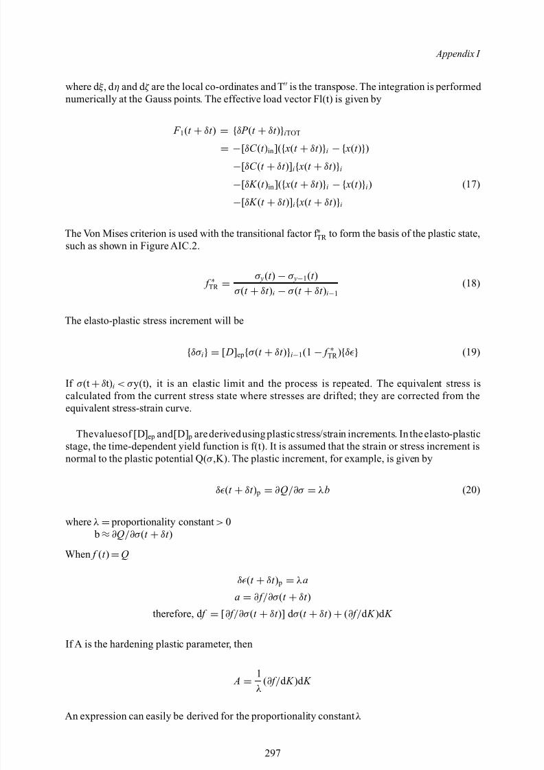
8/10/2019 Lifts Elevators Escalators and Moving Walkways Travelators 2DE2
http://slidepdf.com/reader/full/lifts-elevators-escalators-and-moving-walkways-travelators-2de2 108/169
Appendix I
where d ξ , d η and d ζ are the local co-ordinates and T is the transpose. The integration is performed numerically at the Gauss points. The effective load vector Fl(t) is given by
F 1(t + δt ) = {δ P (t + δt )}iTOT
= −[δC (t )in ]({ x(t + δt )}i − { x(t )})−[δC (t + δt )] i{ x(t + δt )}i
−[δ K (t )in ]({ x(t + δt )}i − { x(t )}i) (17)
−[δ K (t + δt )] i{ x(t + δt )}i
The Von Mises criterion is used with the transitional factor f ∗TR to form the basis of the plastic state,such as shown in Figure AIC.2.
f ∗TR = σ y(t ) − σ y−1(t )
σ (t + δt )i − σ (t + δt )i−1(18)
The elasto-plastic stress increment will be
{δσ i} = [ D]ep{σ (t + δt )}i−1(1 − f ∗TR ){δ } (19)
If σ (t +δt)i < σ y(t), it is an elastic limit and the process is repeated. The equivalent stress iscalculated from the current stress state where stresses are drifted; they are corrected from theequivalent stress-strain curve.
Thevaluesof [D] ep and[D] p arederivedusing plasticstress/strain increments. In theelasto-plasticstage, the time-dependent yield function is f(t). It is assumed that the strain or stress increment isnormal to the plastic potential Q( σ ,K). The plastic increment, for example, is given by
δ (t + δt ) p = ∂Q /∂σ = λ b (20)
where λ = proportionality constant > 0
b≈∂
Q/∂σ
(t + δ
t )When f (t ) =Q
δ (t + δt ) p = λ a
a = ∂ f /∂σ (t + δt )
therefore, d f = [∂ f /∂σ (t + δt )] d σ (t + δt ) + (∂ f / d K )d K
If A is the hardening plastic parameter, then
A = 1λ
(∂ f / d K )d K
An expression can easily be derived for the proportionality constant λ
297
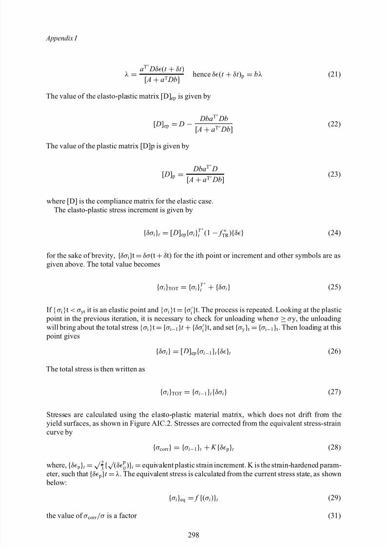
8/10/2019 Lifts Elevators Escalators and Moving Walkways Travelators 2DE2
http://slidepdf.com/reader/full/lifts-elevators-escalators-and-moving-walkways-travelators-2de2 109/169
Appendix I
λ = aT Dδ (t + δt )
[ A + aT Db]hence δ (t + δt ) p = bλ (21)
The value of the elasto-plastic matrix [D] ep is given by
[ D]ep = D − Dba T Db[ A + aT Db]
(22)
The value of the plastic matrix [D]p is given by
[ D] p = Dba T D[ A + aT Db]
(23)
where [D] is the compliance matrix for the elastic case.The elasto-plastic stress increment is given by
{δσ i}t = [ D]ep{σ i}Y ∗t (1 − f ∗TR ){δ } (24)
for the sake of brevity, {δσ i}t =δσ (t +δt) for the ith point or increment and other symbols are asgiven above. The total value becomes
{σ i}TOT = {σ i}Y ∗t + {δσ i} (25)
If {σ i}t < σ yt it is an elastic point and { σ i}t ={σ i}t. The process is repeated. Looking at the plastic point in the previous iteration, it is necessary to check for unloading when σ ≥σ y, the unloadingwill bring about the total stress { σ i}t ={σ i−1}t +{δσ i}t, and set {σ y}t ={σ i−1}t . Then loading at this point gives
{δσ i} = [ D]ep{σ i−1}t {δ }t (26)
The total stress is then written as
{σ i}TOT = {σ i−1}t {δσ i} (27)
Stresses are calculated using the elasto-plastic material matrix, which does not drift from theyield surfaces, as shown in Figure AIC.2. Stresses are corrected from the equivalent stress-straincurve by
{σ corr } = {σ i−1}t + K {δ p}t (28)
where, {δ p}t =√ 23 {√ (δ p
ij )}i =equivalent plastic strain increment. K is the strain-hardened param-eter, such that
{δ p
}t
=λ . The equivalent stress is calculated from the current stress state, as shown
below:
{σ i}eq = f {(σ i)}t (29)
the value of σ corr /σ is a factor (31)
298
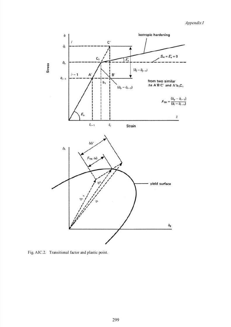
8/10/2019 Lifts Elevators Escalators and Moving Walkways Travelators 2DE2
http://slidepdf.com/reader/full/lifts-elevators-escalators-and-moving-walkways-travelators-2de2 110/169
Appendix I
Fig. AIC.2. Transitional factor and plastic point.
299
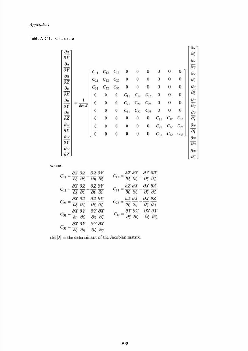
8/10/2019 Lifts Elevators Escalators and Moving Walkways Travelators 2DE2
http://slidepdf.com/reader/full/lifts-elevators-escalators-and-moving-walkways-travelators-2de2 111/169
Appendix I
Table AIC.1. Chain rule
300
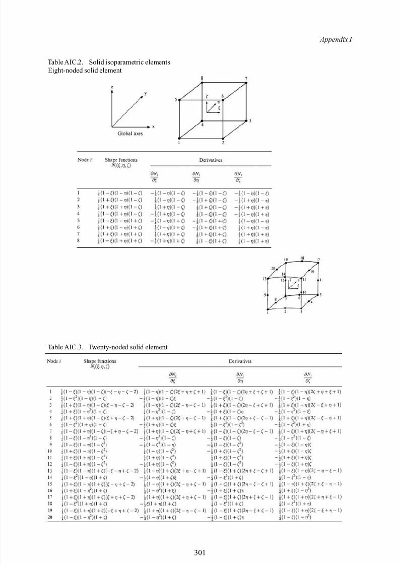
8/10/2019 Lifts Elevators Escalators and Moving Walkways Travelators 2DE2
http://slidepdf.com/reader/full/lifts-elevators-escalators-and-moving-walkways-travelators-2de2 112/169
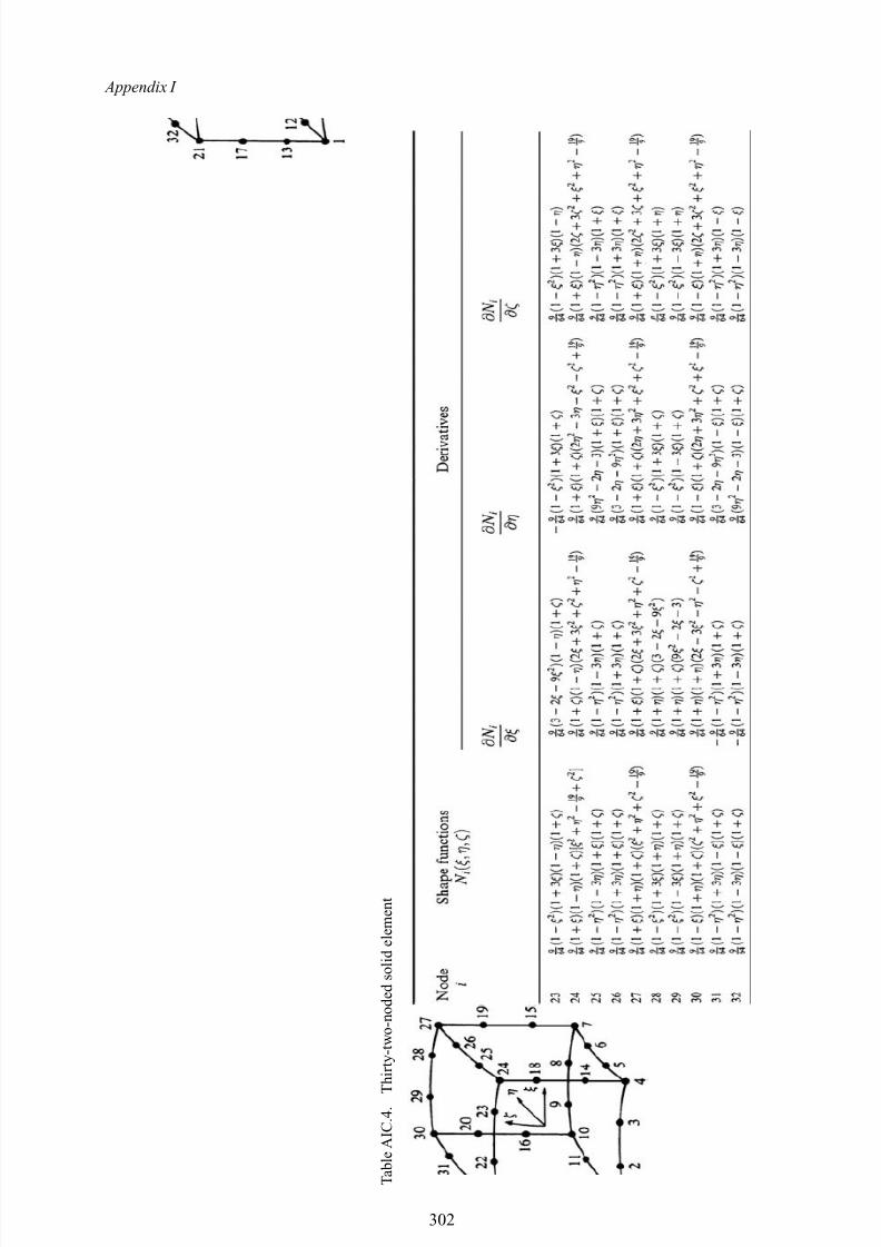
8/10/2019 Lifts Elevators Escalators and Moving Walkways Travelators 2DE2
http://slidepdf.com/reader/full/lifts-elevators-escalators-and-moving-walkways-travelators-2de2 113/169
Appendix I
T a b l e A I C
. 4 . T h i r t y - t w o - n o d e d s o l i d e l e m e n t
302
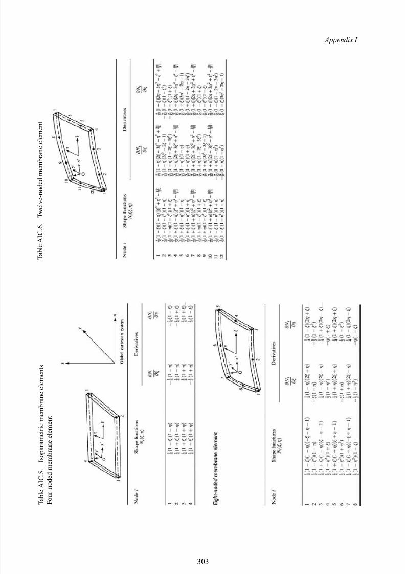
8/10/2019 Lifts Elevators Escalators and Moving Walkways Travelators 2DE2
http://slidepdf.com/reader/full/lifts-elevators-escalators-and-moving-walkways-travelators-2de2 114/169
Appendix I
T a b l e A I C
. 5 . I s o p a r a m e t r i c m e m b r a n e e l e m e n t s
F o u r - n o d e d m e m b r a n e e l e m e n t
T a b l e A I C
. 6 . T w e l v e - n o d e d m e m b r a n e e l e m e n t
303
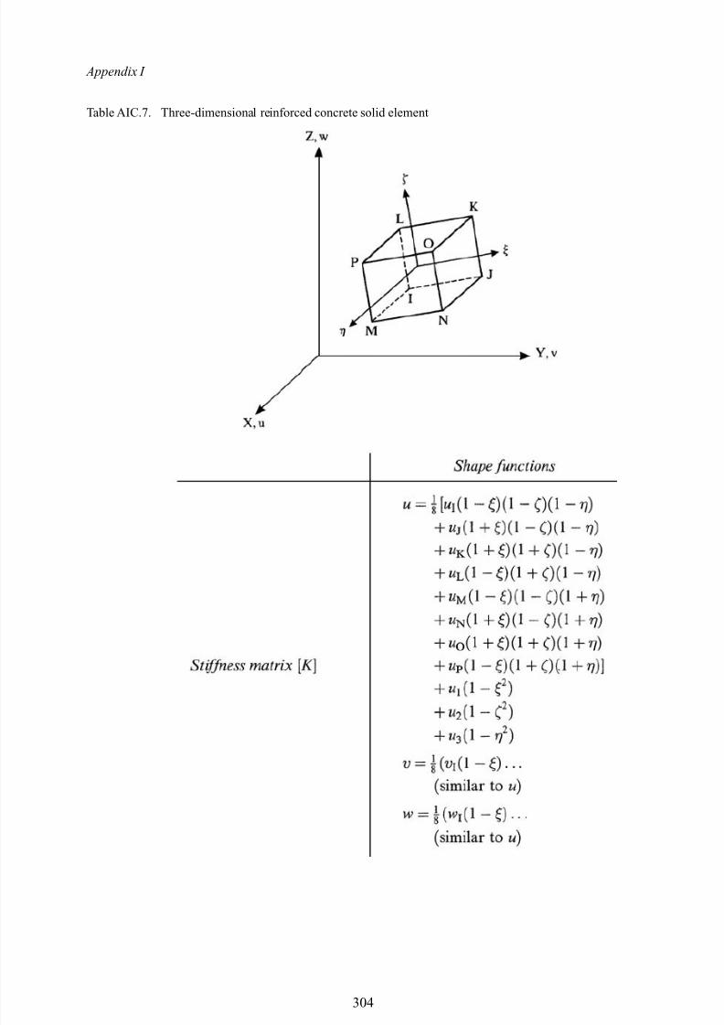
8/10/2019 Lifts Elevators Escalators and Moving Walkways Travelators 2DE2
http://slidepdf.com/reader/full/lifts-elevators-escalators-and-moving-walkways-travelators-2de2 115/169
Appendix I
Table AIC.7. Three-dimensional reinforced concrete solid element
304
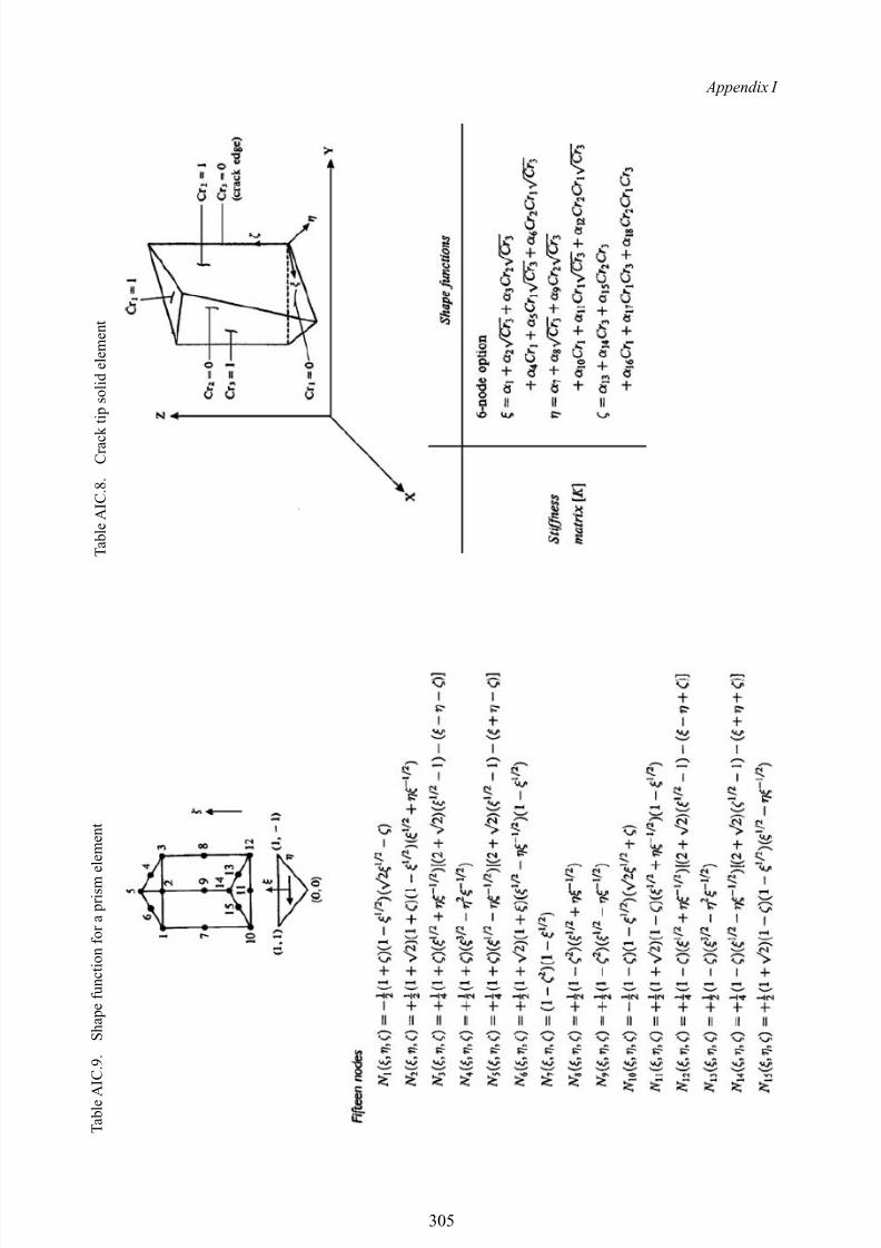
8/10/2019 Lifts Elevators Escalators and Moving Walkways Travelators 2DE2
http://slidepdf.com/reader/full/lifts-elevators-escalators-and-moving-walkways-travelators-2de2 116/169
Appendix I
T a b l e A I C
. 9 . S h a p e f u n c t i o n f o r a p r i s m e l e m e n t
T a b l e A I C
. 8 . C r a c k t i p s o l i d e l e m e n t
305
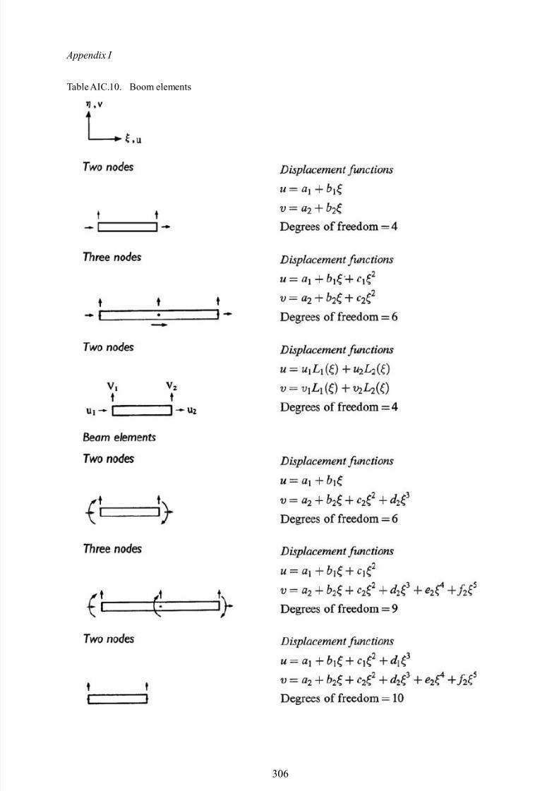
8/10/2019 Lifts Elevators Escalators and Moving Walkways Travelators 2DE2
http://slidepdf.com/reader/full/lifts-elevators-escalators-and-moving-walkways-travelators-2de2 117/169
Appendix I
Table AIC.10. Boom elements
306
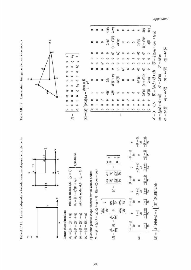
8/10/2019 Lifts Elevators Escalators and Moving Walkways Travelators 2DE2
http://slidepdf.com/reader/full/lifts-elevators-escalators-and-moving-walkways-travelators-2de2 118/169
Appendix I
T a b l e A I C
. 1 1 . L i n e a r a n d q u a d r a t i c t w o - d i m e n s i o n a l d i s p a r a m e t r i c e l e m e n t s
T a b l e A I C
. 1 2 . L i n e a r s t r a i n t r i a n g u l a r e l e m e n t ( s i x - n o d e d )
307
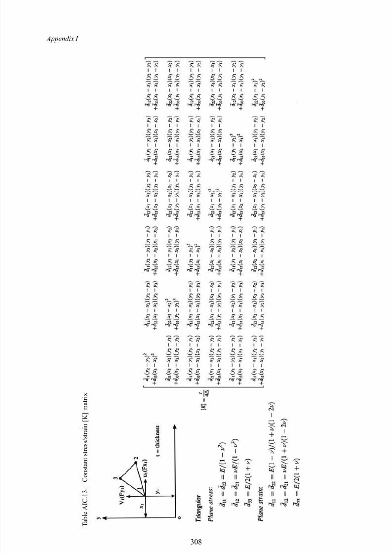
8/10/2019 Lifts Elevators Escalators and Moving Walkways Travelators 2DE2
http://slidepdf.com/reader/full/lifts-elevators-escalators-and-moving-walkways-travelators-2de2 119/169
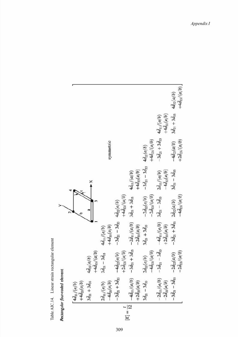
8/10/2019 Lifts Elevators Escalators and Moving Walkways Travelators 2DE2
http://slidepdf.com/reader/full/lifts-elevators-escalators-and-moving-walkways-travelators-2de2 120/169
Appendix I
T a b l e A I C
. 1 4 . L i n e a r s t r a i n r e c t a n g u l a r e l e m e n t
309
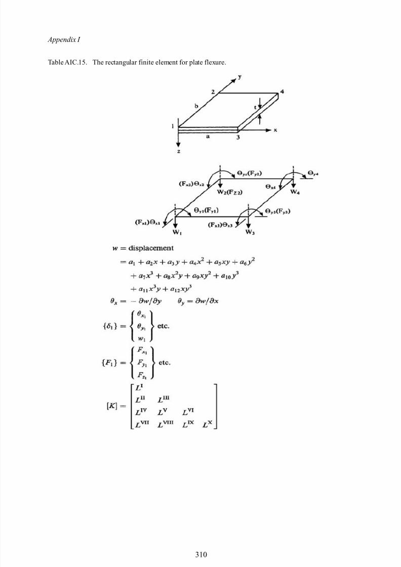
8/10/2019 Lifts Elevators Escalators and Moving Walkways Travelators 2DE2
http://slidepdf.com/reader/full/lifts-elevators-escalators-and-moving-walkways-travelators-2de2 121/169
Appendix I
Table AIC.15. The rectangular finite element for plate flexure.
310
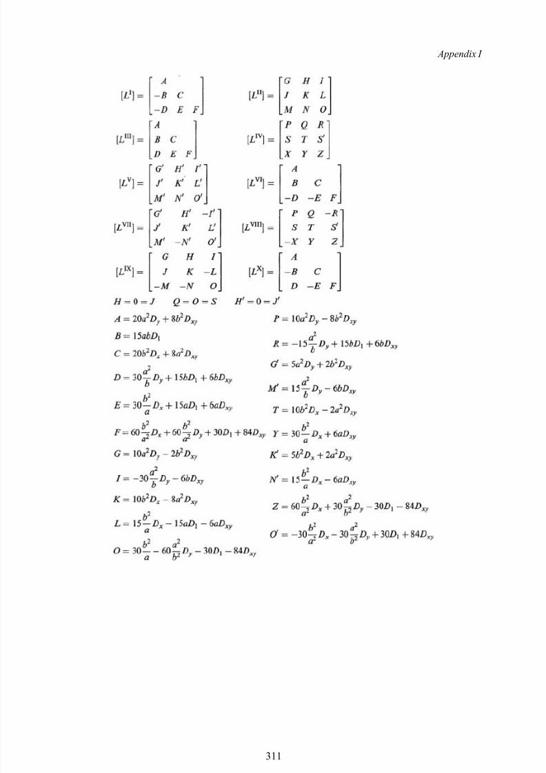
8/10/2019 Lifts Elevators Escalators and Moving Walkways Travelators 2DE2
http://slidepdf.com/reader/full/lifts-elevators-escalators-and-moving-walkways-travelators-2de2 122/169
Appendix I
311
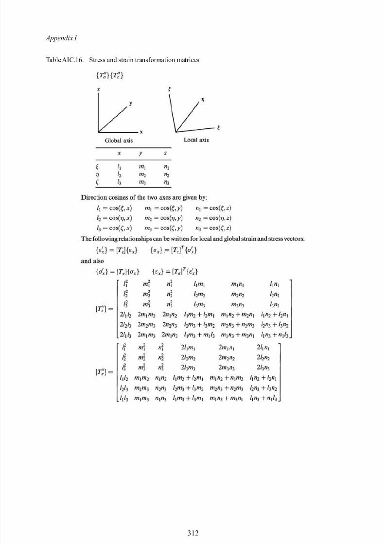
8/10/2019 Lifts Elevators Escalators and Moving Walkways Travelators 2DE2
http://slidepdf.com/reader/full/lifts-elevators-escalators-and-moving-walkways-travelators-2de2 123/169
Appendix I
Table AIC.16. Stress and strain transformation matrices
312
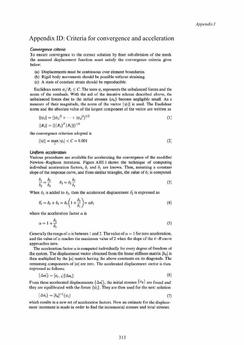
8/10/2019 Lifts Elevators Escalators and Moving Walkways Travelators 2DE2
http://slidepdf.com/reader/full/lifts-elevators-escalators-and-moving-walkways-travelators-2de2 124/169
Appendix I
Appendix ID: Criteria for convergence and acceleration
313
8/10/2019 Lifts Elevators Escalators and Moving Walkways Travelators 2DE2
http://slidepdf.com/reader/full/lifts-elevators-escalators-and-moving-walkways-travelators-2de2 125/169
Appendix I
314

8/10/2019 Lifts Elevators Escalators and Moving Walkways Travelators 2DE2
http://slidepdf.com/reader/full/lifts-elevators-escalators-and-moving-walkways-travelators-2de2 126/169
Appendix II
Computer Programs

8/10/2019 Lifts Elevators Escalators and Moving Walkways Travelators 2DE2
http://slidepdf.com/reader/full/lifts-elevators-escalators-and-moving-walkways-travelators-2de2 127/169
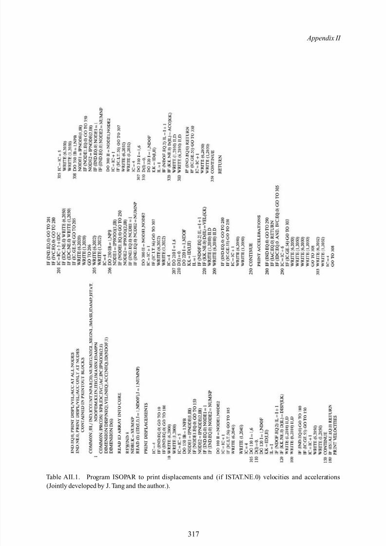
8/10/2019 Lifts Elevators Escalators and Moving Walkways Travelators 2DE2
http://slidepdf.com/reader/full/lifts-elevators-escalators-and-moving-walkways-travelators-2de2 128/169
Appendix II
Table AII.1. Program ISOPAR to print displacements and (if ISTAT.NE.0) velocities and accelerations(Jointly developed by J. Tang and the author.).
317

8/10/2019 Lifts Elevators Escalators and Moving Walkways Travelators 2DE2
http://slidepdf.com/reader/full/lifts-elevators-escalators-and-moving-walkways-travelators-2de2 129/169
Appendix II
Table AII. 1. Algorithm for principal stresses
318
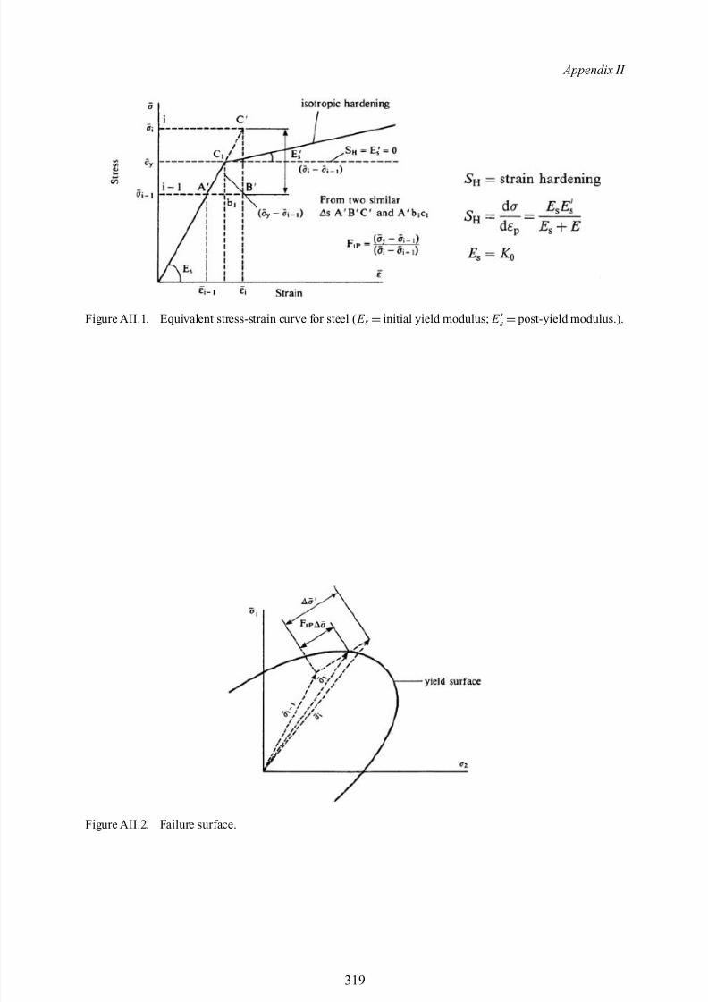
8/10/2019 Lifts Elevators Escalators and Moving Walkways Travelators 2DE2
http://slidepdf.com/reader/full/lifts-elevators-escalators-and-moving-walkways-travelators-2de2 130/169
Appendix II
Figure AII.1. Equivalent stress-strain curve for steel ( E s =initial yield modulus; E s = post-yield modulus.).
Figure AII.2. Failure surface.
319
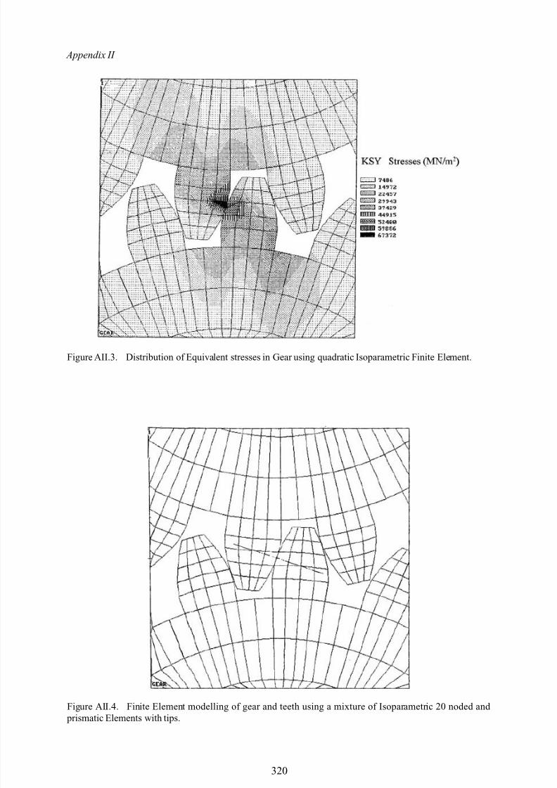
8/10/2019 Lifts Elevators Escalators and Moving Walkways Travelators 2DE2
http://slidepdf.com/reader/full/lifts-elevators-escalators-and-moving-walkways-travelators-2de2 131/169
Appendix II
Figure AII.3. Distribution of Equivalent stresses in Gear using quadratic Isoparametric Finite Element.
Figure AII.4. Finite Element modelling of gear and teeth using a mixture of Isoparametric 20 noded and prismatic Elements with tips.
320
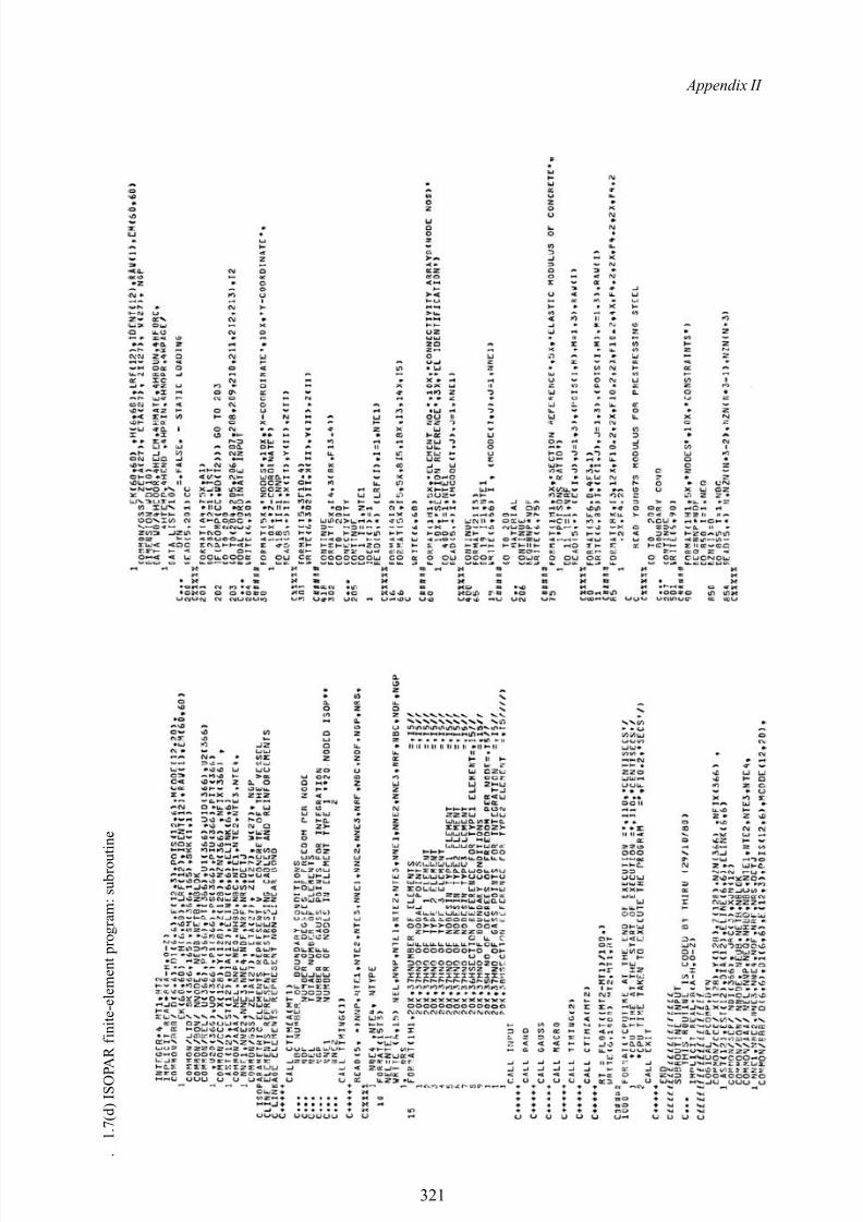
8/10/2019 Lifts Elevators Escalators and Moving Walkways Travelators 2DE2
http://slidepdf.com/reader/full/lifts-elevators-escalators-and-moving-walkways-travelators-2de2 132/169
Appendix II
. 1 . 7 ( d ) I S O P A R f i n i t e - e l e m e n t p r o g r a m : s u b r o u t i n e
321
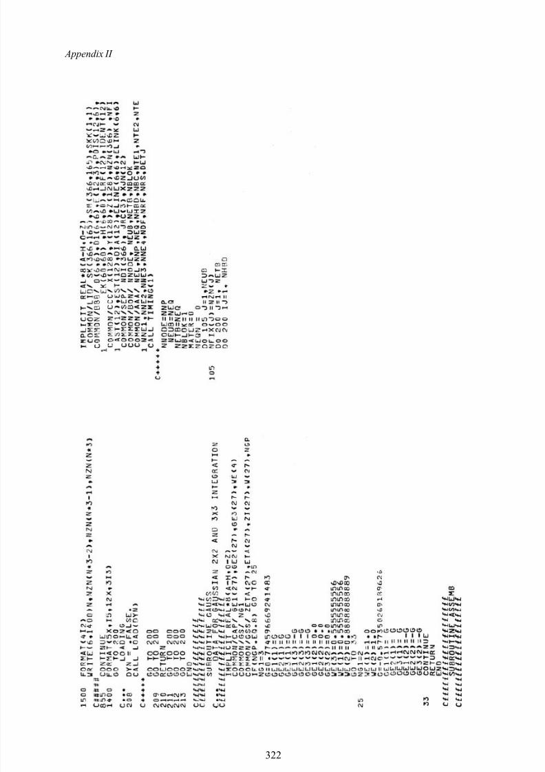
8/10/2019 Lifts Elevators Escalators and Moving Walkways Travelators 2DE2
http://slidepdf.com/reader/full/lifts-elevators-escalators-and-moving-walkways-travelators-2de2 133/169
Appendix II
322
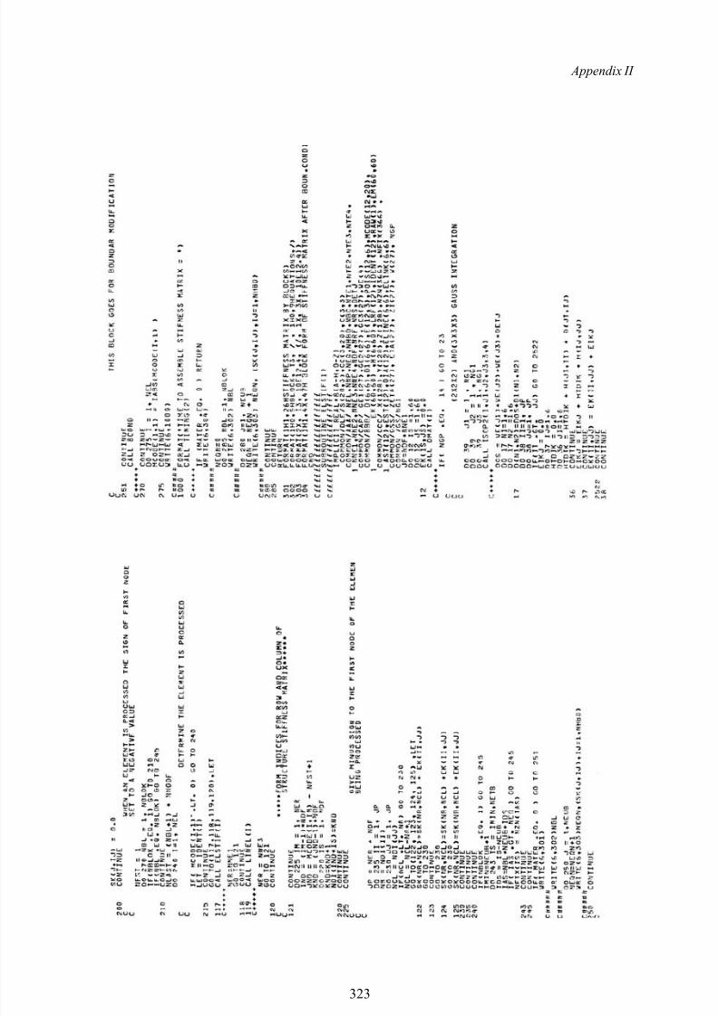
8/10/2019 Lifts Elevators Escalators and Moving Walkways Travelators 2DE2
http://slidepdf.com/reader/full/lifts-elevators-escalators-and-moving-walkways-travelators-2de2 134/169
Appendix II
323
8/10/2019 Lifts Elevators Escalators and Moving Walkways Travelators 2DE2
http://slidepdf.com/reader/full/lifts-elevators-escalators-and-moving-walkways-travelators-2de2 135/169
8/10/2019 Lifts Elevators Escalators and Moving Walkways Travelators 2DE2
http://slidepdf.com/reader/full/lifts-elevators-escalators-and-moving-walkways-travelators-2de2 136/169
Appendix II
325
8/10/2019 Lifts Elevators Escalators and Moving Walkways Travelators 2DE2
http://slidepdf.com/reader/full/lifts-elevators-escalators-and-moving-walkways-travelators-2de2 137/169
Appendix II
326
8/10/2019 Lifts Elevators Escalators and Moving Walkways Travelators 2DE2
http://slidepdf.com/reader/full/lifts-elevators-escalators-and-moving-walkways-travelators-2de2 138/169
Appendix II
327
8/10/2019 Lifts Elevators Escalators and Moving Walkways Travelators 2DE2
http://slidepdf.com/reader/full/lifts-elevators-escalators-and-moving-walkways-travelators-2de2 139/169
Appendix II
328
8/10/2019 Lifts Elevators Escalators and Moving Walkways Travelators 2DE2
http://slidepdf.com/reader/full/lifts-elevators-escalators-and-moving-walkways-travelators-2de2 140/169
Appendix II
329
8/10/2019 Lifts Elevators Escalators and Moving Walkways Travelators 2DE2
http://slidepdf.com/reader/full/lifts-elevators-escalators-and-moving-walkways-travelators-2de2 141/169
Appendix II
330
8/10/2019 Lifts Elevators Escalators and Moving Walkways Travelators 2DE2
http://slidepdf.com/reader/full/lifts-elevators-escalators-and-moving-walkways-travelators-2de2 142/169
Appendix II
331
8/10/2019 Lifts Elevators Escalators and Moving Walkways Travelators 2DE2
http://slidepdf.com/reader/full/lifts-elevators-escalators-and-moving-walkways-travelators-2de2 143/169

8/10/2019 Lifts Elevators Escalators and Moving Walkways Travelators 2DE2
http://slidepdf.com/reader/full/lifts-elevators-escalators-and-moving-walkways-travelators-2de2 144/169
8/10/2019 Lifts Elevators Escalators and Moving Walkways Travelators 2DE2
http://slidepdf.com/reader/full/lifts-elevators-escalators-and-moving-walkways-travelators-2de2 145/169

8/10/2019 Lifts Elevators Escalators and Moving Walkways Travelators 2DE2
http://slidepdf.com/reader/full/lifts-elevators-escalators-and-moving-walkways-travelators-2de2 146/169
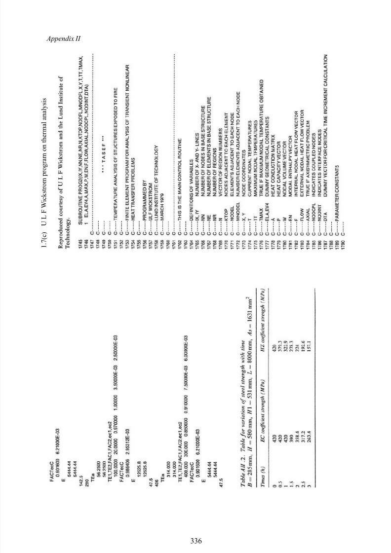
8/10/2019 Lifts Elevators Escalators and Moving Walkways Travelators 2DE2
http://slidepdf.com/reader/full/lifts-elevators-escalators-and-moving-walkways-travelators-2de2 147/169
Appendix II
1 . 7 ( c ) U L F W i c k s t r o m p r o g r a m o n t h e r m a l a n a l y s i s
336
8/10/2019 Lifts Elevators Escalators and Moving Walkways Travelators 2DE2
http://slidepdf.com/reader/full/lifts-elevators-escalators-and-moving-walkways-travelators-2de2 148/169
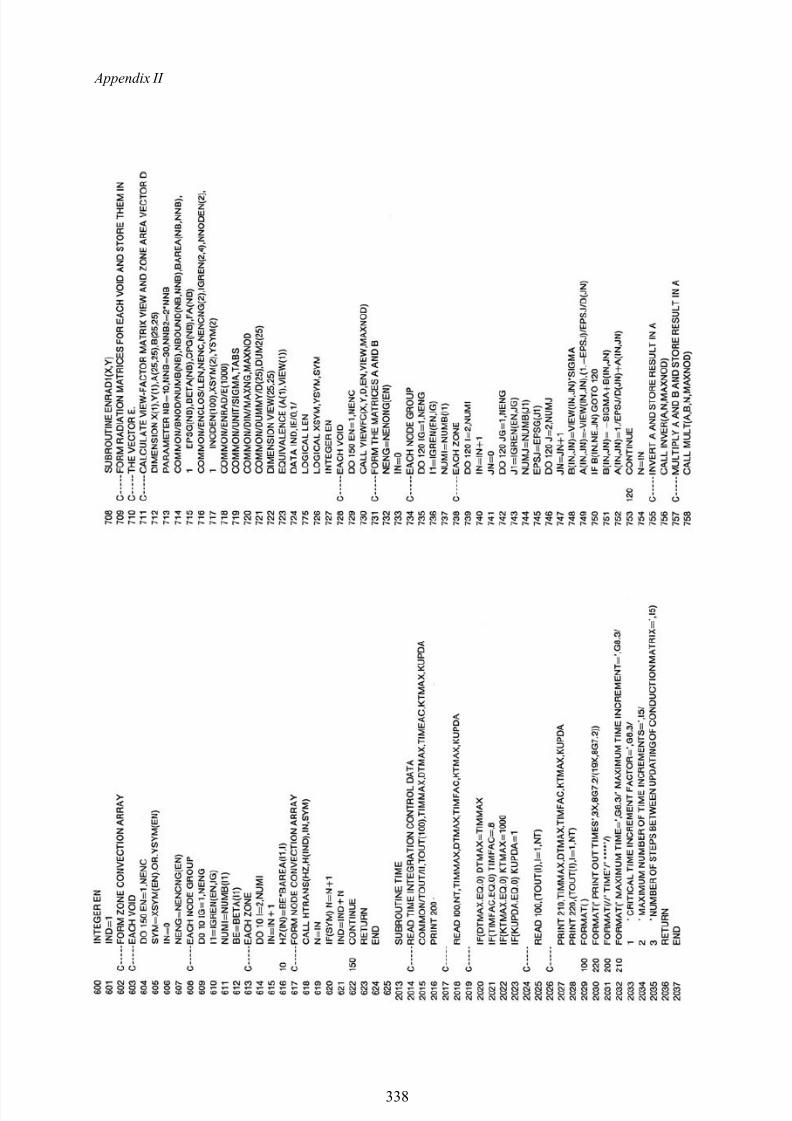
8/10/2019 Lifts Elevators Escalators and Moving Walkways Travelators 2DE2
http://slidepdf.com/reader/full/lifts-elevators-escalators-and-moving-walkways-travelators-2de2 149/169
Appendix II
338

8/10/2019 Lifts Elevators Escalators and Moving Walkways Travelators 2DE2
http://slidepdf.com/reader/full/lifts-elevators-escalators-and-moving-walkways-travelators-2de2 150/169
Appendix II
339
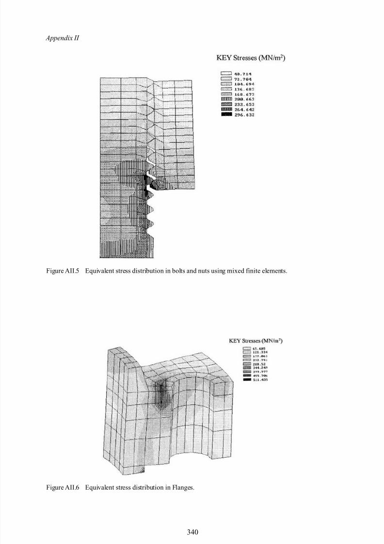
8/10/2019 Lifts Elevators Escalators and Moving Walkways Travelators 2DE2
http://slidepdf.com/reader/full/lifts-elevators-escalators-and-moving-walkways-travelators-2de2 151/169
Appendix II
Figure AII.5 Equivalent stress distribution in bolts and nuts using mixed finite elements.
Figure AII.6 Equivalent stress distribution in Flanges.
340
8/10/2019 Lifts Elevators Escalators and Moving Walkways Travelators 2DE2
http://slidepdf.com/reader/full/lifts-elevators-escalators-and-moving-walkways-travelators-2de2 152/169
Appendix III
Dynamic Finite Element Analysis-SolutionProcedures

8/10/2019 Lifts Elevators Escalators and Moving Walkways Travelators 2DE2
http://slidepdf.com/reader/full/lifts-elevators-escalators-and-moving-walkways-travelators-2de2 153/169
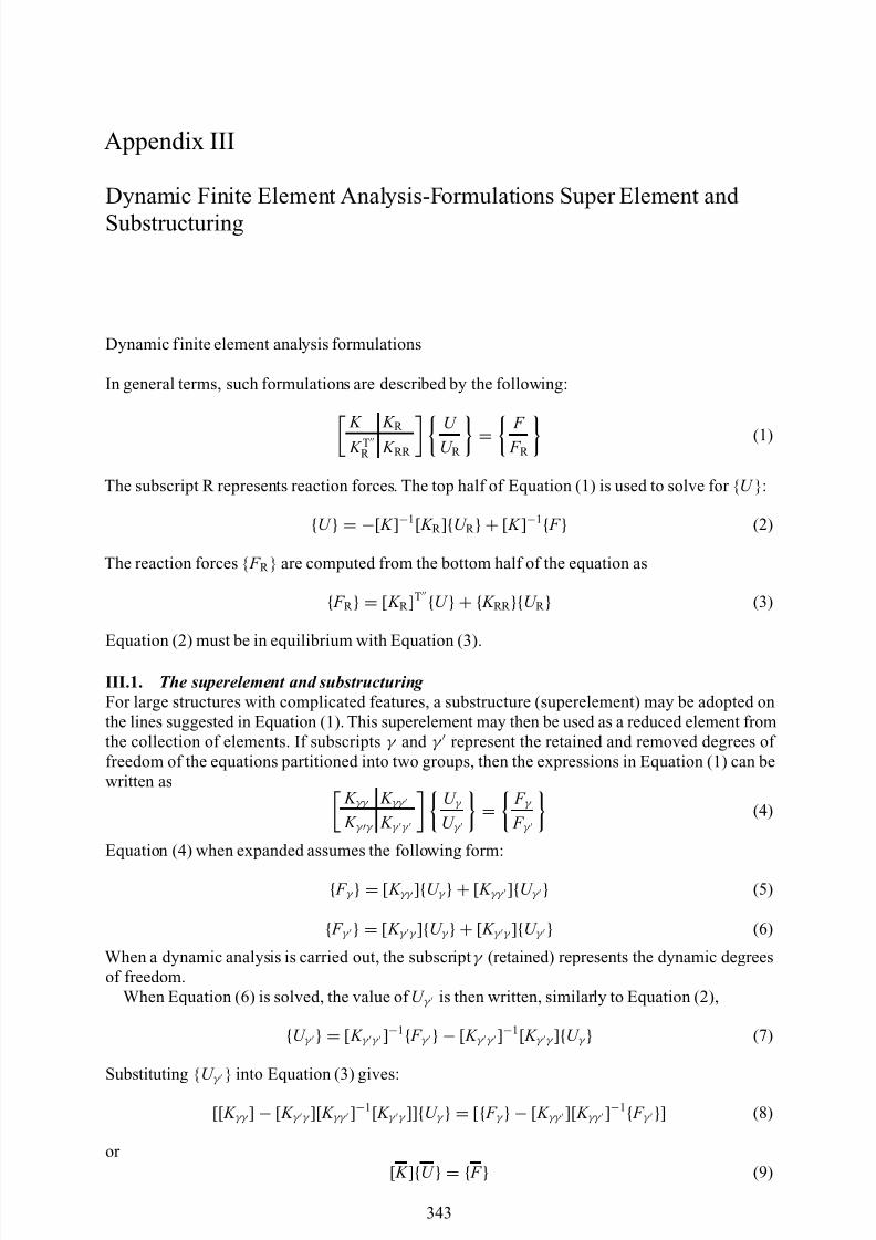
8/10/2019 Lifts Elevators Escalators and Moving Walkways Travelators 2DE2
http://slidepdf.com/reader/full/lifts-elevators-escalators-and-moving-walkways-travelators-2de2 154/169
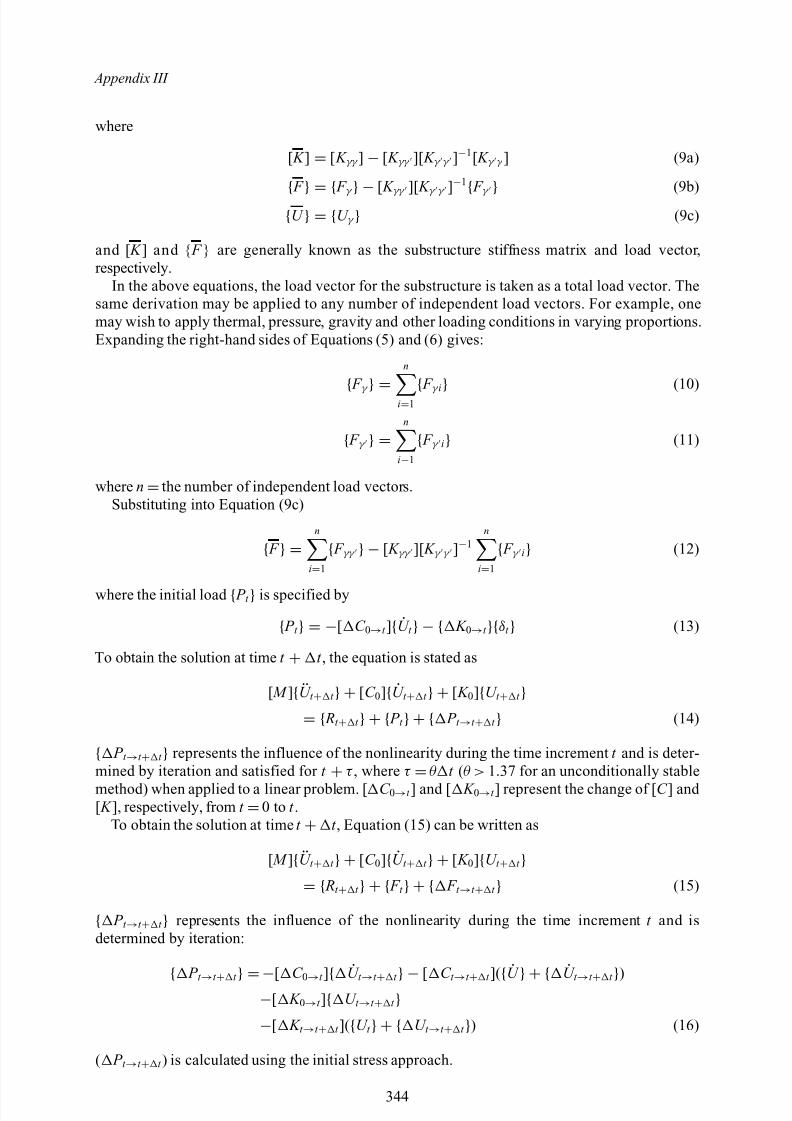
8/10/2019 Lifts Elevators Escalators and Moving Walkways Travelators 2DE2
http://slidepdf.com/reader/full/lifts-elevators-escalators-and-moving-walkways-travelators-2de2 155/169
Appendix III
where
[ K ] = [ K γγ ] − [ K γγ ][ K γ γ ]−1[ K γ γ ] (9a)
{ F
} = { F γ
} − [ K γγ ][ K γ γ ]−1
{ F γ
} (9b)
{U } = {U γ } (9c)
and [ K ] and { F } are generally known as the substructure stiffness matrix and load vector,respectively.
In the above equations, the load vector for the substructure is taken as a total load vector. Thesame derivation may be applied to any number of independent load vectors. For example, onemay wish to apply thermal, pressure, gravity and other loading conditions in varying proportions.Expanding the right-hand sides of Equations (5) and (6) gives:
{ F
γ } =
n
i=1 { F
γ i} (10)
{ F γ } =n
i−1{ F γ i} (11)
where n =the number of independent load vectors.Substituting into Equation (9c)
{ F } =n
i=1{ F γγ } − [ K γγ ][ K γ γ ]−1
n
i=1{ F γ i} (12)
where the initial load { P t } is specified by
{ P t } = −[ C 0→t ]{ U t } − { K 0→t }{δt } (13)
To obtain the solution at time t + t , the equation is stated as
[ M ]{ U t + t } + [C 0]{ U t + t } + [ K 0]{U t + t }= { Rt + t } + { P t } + { P t →t + t } (14)
{ P t →t + t } represents the influence of the nonlinearity during the time increment t and is deter-mined by iteration and satisfied for t
+ τ , where τ
=θ t (θ > 1.37 for an unconditionally stable
method) when applied to a linear problem. [ C 0→t ] and [ K 0→t ] represent the change of [ C ] and [ K ], respectively, from t =0 to t .
To obtain the solution at time t + t , Equation (15) can be written as
[ M ]{ U t + t } + [C 0]{ U t + t } + [ K 0]{U t + t }= { Rt + t } + { F t } + { F t →t + t } (15)
{ P t →t + t } represents the influence of the nonlinearity during the time increment t and isdetermined by iteration:
{ P
t →t + t } =−[ C
0→t ]
{ U
t →t + t } − [ C
t →t + t ](
{ U
} + { U
t →t + t })
−[ K 0→t ]{ U t →t + t }−[ K t →t + t ]({U t } + {U t →t + t }) (16)
( P t →t + t ) is calculated using the initial stress approach.
344
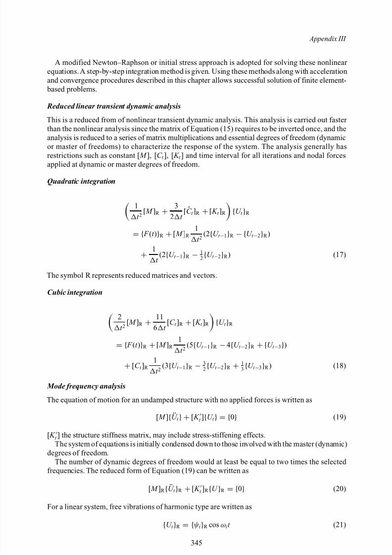
8/10/2019 Lifts Elevators Escalators and Moving Walkways Travelators 2DE2
http://slidepdf.com/reader/full/lifts-elevators-escalators-and-moving-walkways-travelators-2de2 156/169
Appendix III
A modified Newton–Raphson or initial stress approach is adopted for solving these nonlinear equations.A step-by-step integration method is given. Using these methods along with accelerationand convergence procedures described in this chapter allows successful solution of finite element- based problems.
Reduced linear transient dynamic analysis
This is a reduced from of nonlinear transient dynamic analysis. This analysis is carried out faster than the nonlinear analysis since the matrix of Equation (15) requires to be inverted once, and theanalysis is reduced to a series of matrix multiplications and essential degrees of freedom (dynamicor master of freedoms) to characterize the response of the system. The analysis generally hasrestrictions such as constant [ M ], [C t ], [ K t ] and time interval for all iterations and nodal forcesapplied at dynamic or master degrees of freedom.
Quadratic integration
1t 2
[ M ]R + 32 t
[C t ]R + [ K t ]R {U t }R
= { F (t )}R + [ M ]R 1t 2
(2{U t −1}R − {U t −2}R )
+ 1
t (2{U t −1}R − 1
2{U t −2}R ) (17)
The symbol R represents reduced matrices and vectors.
Cubic integration
2t 2
[ M ]R + 116 t
[C t ]R + [ K t ]R {U t }R
= { F (t )}R + [ M ]R 1t 2
(5{U t −1}R − 4{U t −2}R + {U t −3})
+ [C t ]R 1t 2
(3{U t −1}R − 32{U t −2}R + 1
3 {U t −3}R ) (18)
Mode frequency analysisThe equation of motion for an undamped structure with no applied forces is written as
[ M ]{ U t } + [ K t ]{U t } = {0} (19)
[ K t ] the structure stiffness matrix, may include stress-stiffening effects.The system of equations is initially condensed down to those involved with the master (dynamic)
degrees of freedom.The number of dynamic degrees of freedom would at least be equal to two times the selected
frequencies. The reduced form of Equation (19) can be written as
[ M ]R { U t }R + [ K t ]R {U }R = {0} (20)
For a linear system, free vibrations of harmonic type are written as
{U t }R = {ψ i}R cos ω i t (21)
345
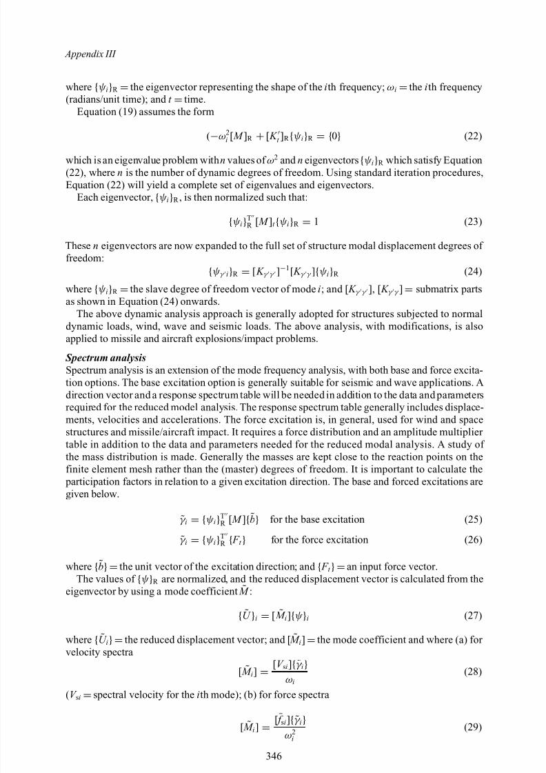
8/10/2019 Lifts Elevators Escalators and Moving Walkways Travelators 2DE2
http://slidepdf.com/reader/full/lifts-elevators-escalators-and-moving-walkways-travelators-2de2 157/169
Appendix III
where {ψ i}R =the eigenvector representing the shape of the ith frequency; ω i =the ith frequency(radians/unit time); and t =time.
Equation (19) assumes the form
(−ω2i [ M ]R + [ K t ]R {ψ i}R = {0} (22)
which is an eigenvalue problem with n values of ω2 and n eigenvectors {ψ i}R which satisfy Equation(22), where n is the number of dynamic degrees of freedom. Using standard iteration procedures,Equation (22) will yield a complete set of eigenvalues and eigenvectors.
Each eigenvector, {ψ i}R , is then normalized such that:
{ψ i}TR [ M ]t {ψ i}R = 1 (23)
These n eigenvectors are now expanded to the full set of structure modal displacement degrees of freedom:
{ψ γ i}R = [ K γ γ ]−1[ K γ γ ]{ψ i}R (24)where {ψ i}R =the slave degree of freedom vector of mode i; and [ K γ γ ], [ K γ γ ] = submatrix partsas shown in Equation (24) onwards.
The above dynamic analysis approach is generally adopted for structures subjected to normaldynamic loads, wind, wave and seismic loads. The above analysis, with modifications, is alsoapplied to missile and aircraft explosions/impact problems.
Spectrum analysisSpectrum analysis is an extension of the mode frequency analysis, with both base and force excita-tion options. The base excitation option is generally suitable for seismic and wave applications. Adirection vector and a response spectrum table will be needed in addition to the data and parametersrequired for the reduced model analysis. The response spectrum table generally includes displace-ments, velocities and accelerations. The force excitation is, in general, used for wind and spacestructures and missile/aircraft impact. It requires a force distribution and an amplitude multiplier table in addition to the data and parameters needed for the reduced modal analysis. A study of the mass distribution is made. Generally the masses are kept close to the reaction points on thefinite element mesh rather than the (master) degrees of freedom. It is important to calculate the participation factors in relation to a given excitation direction. The base and forced excitations aregiven below.
˜γ i = {ψ i}TR [ M ]{b} for the base excitation (25)
˜γ i = {ψ i}TR { F t } for the force excitation (26)
where {b}=the unit vector of the excitation direction; and { F t }=an input force vector.The values of {ψ }R are normalized, and the reduced displacement vector is calculated from the
eigenvector by using a mode coefficient ˜ M :
{ U }i = [ ˜ M i]{ψ }i (27)
where { U i}=the reduced displacement vector; and [ ˜ M i] =the mode coefficient and where (a) for velocity spectra
[
˜ M
i]
= [V si]
{˜γ i
}ω i(28)
(V si =spectral velocity for the ith mode); (b) for force spectra
[ ˜ M i] = [¯ f si]{˜γ i}
ω2i
(29)
346
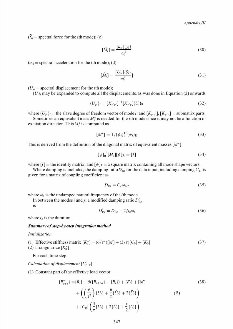
8/10/2019 Lifts Elevators Escalators and Moving Walkways Travelators 2DE2
http://slidepdf.com/reader/full/lifts-elevators-escalators-and-moving-walkways-travelators-2de2 158/169
Appendix III
(¯ f si =spectral force for the ith mode); (c)
[ ˜ M i] = [a si]{˜γ i}
ω2i
(30)
(a si =spectral acceleration for the ith mode); (d)
[ ˜ M t ] = [U si]{˜γ i}
ω2i
] (31)
(U si =spectral displacement for the ith mode);
{U }i may be expanded to compute all the displacements, as was done in Equation (2) onwards.
{U γ }i = [ K γ γ ]−1[ K γ γ ]{U i}R (32)
where {U γ }i =the slave degree of freedom vector of mode i; and [ K γ γ ], [ K γ γ ] = submatrix parts.Sometimes an equivalent mass M ei is needed for the ith mode since it may not be a function of excitation direction. This M ei is computed as
[ M ei ] = 1/ {ψ i}TR {ψ i}R (33)
This is derived from the definition of the diagonal matrix of equivalent masses [ M e]
[ψ ]TR [ M e][ψ ]R = [ I ] (34)
where [ I ] =the identity matrix; and [ ψ ] R =a square matrix containing all mode shape vectors.Where damping is included, the damping ratio DR i for the data input, including damping C e , is
given for a matrix of coupling coefficient as
DR i = C eω i/ 2 (35)
where ω I is the undamped natural frequency of the ith mode.In between the modes i and j , a modified damping ratio DR iis
DR i = DR i + 2/ t eω i (36)
where t e is the duration.
Summary of step-by-step integration method
Initialization
(1) Effective stiffness matrix [ K ∗0 ] =(6/τ 2)[ M ] +(3/τ )[C 0] +[ K 0] (37)(2) Triangularize [ K ∗0 ]
For each time step:
Calculation of displacement {U t +τ }(1) Constant part of the effective load vector
{ R∗t +τ } ={ Rt } + θ ({ Rt + t } − { Rt }) + { F t } + [ M ] (38)
+ 6τ 2 {U t } +
6τ { U t } + 2{ U t } (B)
+ [C 0]3τ {U t } + 2{ U t } +
τ 2 {U t }
347
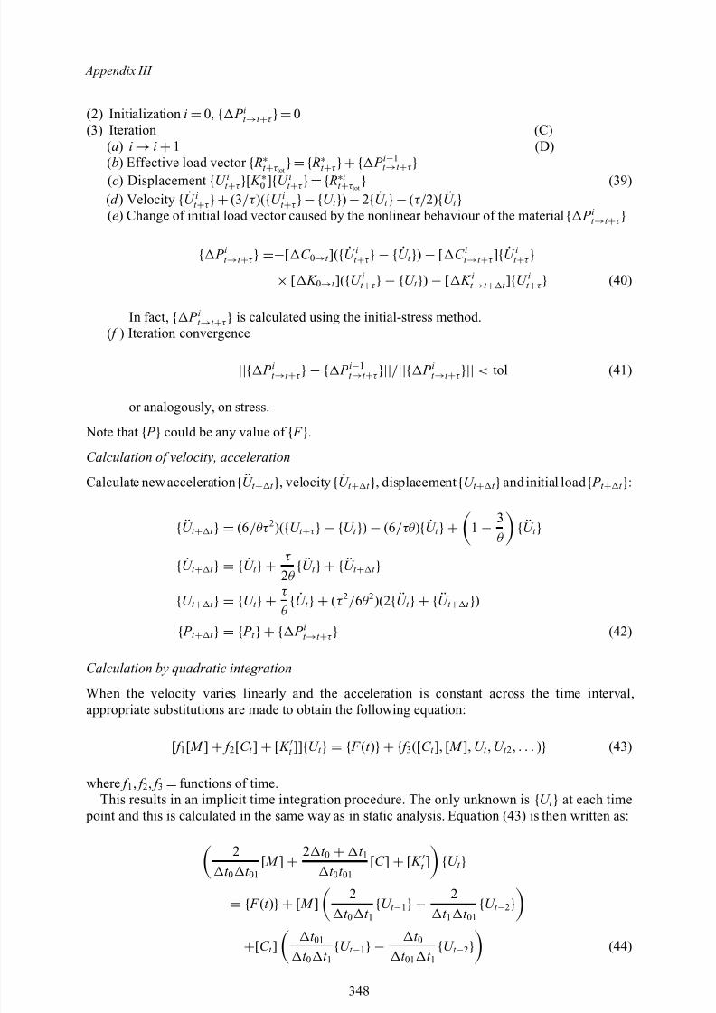
8/10/2019 Lifts Elevators Escalators and Moving Walkways Travelators 2DE2
http://slidepdf.com/reader/full/lifts-elevators-escalators-and-moving-walkways-travelators-2de2 159/169
Appendix III
(2) Initialization i =0, { P it →t +τ }=0(3) Iteration (C)
(a) i →i +1 (D)(b) Effective load vector
{ R∗t
+τ tot
}={ R∗t
+τ
}+{ P i−1
t
→t
+τ
}(c) Displacement {U it +τ }[ K ∗0 ]{U it +τ }={ R∗it +τ tot } (39)(d ) Velocity { U it +τ }+(3/τ )({U it +τ }−{U t }) −2{ U t }−(τ/ 2){ U t }(e) Change of initial load vector caused by the nonlinear behaviour of the material { P it →t +τ }
{ P it →t +τ } =−[ C 0→t ]({ U it +τ } − { U t }) − [ C it →t +τ ]{ U it +τ }× [ K 0→t ]({U it +τ } − {U t }) − [ K it →t + t ]{U it +τ } (40)
In fact, { P it →t +τ } is calculated using the initial-stress method.( f ) Iteration convergence
||{ P it →t +τ } − { P i−1t →t +τ }||/ ||{ P it →t +τ }|| < tol (41)
or analogously, on stress.
Note that { P } could be any value of { F }.Calculation of velocity, acceleration
Calculate new acceleration { U t + t }, velocity { U t + t }, displacement {U t + t }and initial load { P t + t }:
{ U t + t } = (6 /θτ 2
)({U t +τ } − {U t }) − (6/τθ ){ U t } +1 − 3θ { U t }
{ U t + t } = { U t } + τ 2θ { U t } + { U t + t }
{U t + t } = {U t } + τ θ { U t } + (τ 2 / 6θ 2)(2{ U t } + { U t + t })
{ P t + t } = { P t } + { P it →t +τ } (42)
Calculation by quadratic integration
When the velocity varies linearly and the acceleration is constant across the time interval,
appropriate substitutions are made to obtain the following equation:
[ f 1[ M ] + f 2[C t ] + [ K t ]]{U t } = { F (t )} + { f 3([C t ], [ M ], U t , U t 2 , . . . )} (43)
where f 1 , f 2 , f 3 =functions of time.This results in an implicit time integration procedure. The only unknown is {U t } at each time
point and this is calculated in the same way as in static analysis. Equation (43) is then written as:
2t 0 t 01
[ M ] + 2 t 0 + t 1
t 0 t 01[C ] + [ K t ] {U t }
= { F (t )} + [ M ] 2t 0 t 1 {U t −1} −
2t 1 t 01 {U t −2}
+[C t ] t 01
t 0 t 1 {U t −1} − t 0
t 01 t 1 {U t −2} (44)
348
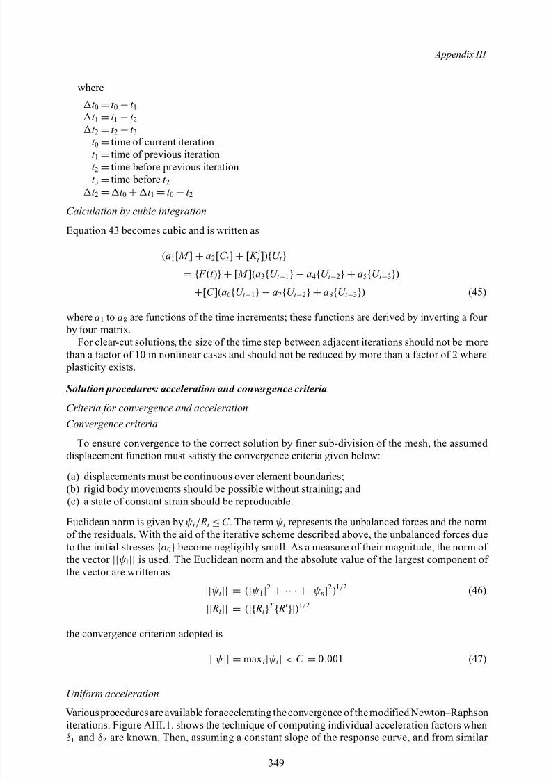
8/10/2019 Lifts Elevators Escalators and Moving Walkways Travelators 2DE2
http://slidepdf.com/reader/full/lifts-elevators-escalators-and-moving-walkways-travelators-2de2 160/169
Appendix III
where
t 0 =t 0 −t 1t 1 =t 1 −t 2t 2
=t 2
−t 3
t 0 =time of current iterationt 1 =time of previous iterationt 2 =time before previous iterationt 3 =time before t 2t 2 = t 0 + t 1 =t 0 −t 2
Calculation by cubic integration
Equation 43 becomes cubic and is written as
(a1[ M ] + a2[C t ] + [ K t ]){U t }= { F (t )} + [ M ](a 3{U t −1} − a4{U t −2} + a5{U t −3})
+[C ](a6{U t −1} − a7{U t −2} + a8{U t −3}) (45)
where a1 to a8 are functions of the time increments; these functions are derived by inverting a four by four matrix.
For clear-cut solutions, the size of the time step between adjacent iterations should not be morethan a factor of 10 in nonlinear cases and should not be reduced by more than a factor of 2 where plasticity exists.
Solution procedures: acceleration and convergence criteria
Criteria for convergence and accelerationConvergence criteria
To ensure convergence to the correct solution by finer sub-division of the mesh, the assumed displacement function must satisfy the convergence criteria given below:
(a) displacements must be continuous over element boundaries;(b) rigid body movements should be possible without straining; and (c) a state of constant strain should be reproducible.
Euclidean norm is given by ψ i / Ri ≤C . The term ψ i represents the unbalanced forces and the normof the residuals. With the aid of the iterative scheme described above, the unbalanced forces due
to the initial stresses {σ 0} become negligibly small. As a measure of their magnitude, the norm of the vector ||ψ i|| is used. The Euclidean norm and the absolute value of the largest component of the vector are written as
||ψ i|| = (|ψ 1|2 + ·· · + |ψ n|2)1/ 2 (46)
|| Ri|| = (|{ Ri}T { Ri}|)1/ 2
the convergence criterion adopted is
||ψ || = max i|ψ i| < C = 0.001 (47)
Uniform acceleration
Variousproceduresareavailable foraccelerating theconvergence of themodified Newton–Raphsoniterations. Figure AIII.1. shows the technique of computing individual acceleration factors whenδ1 and δ2 are known. Then, assuming a constant slope of the response curve, and from similar
349
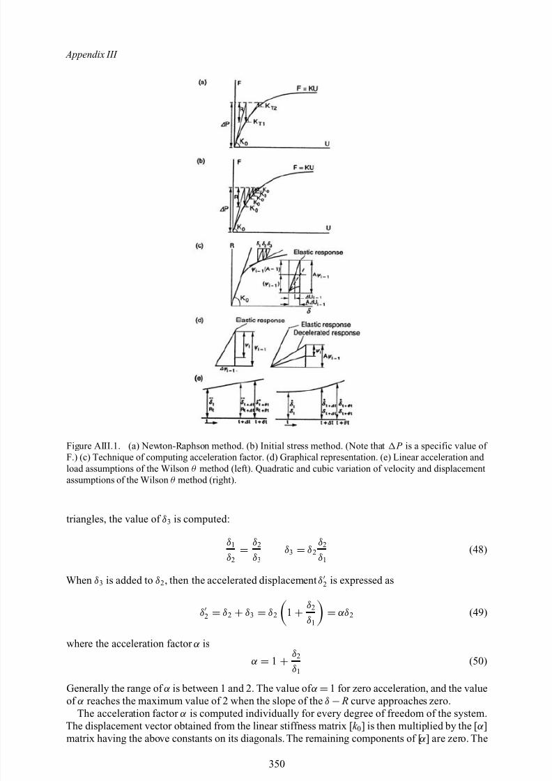
8/10/2019 Lifts Elevators Escalators and Moving Walkways Travelators 2DE2
http://slidepdf.com/reader/full/lifts-elevators-escalators-and-moving-walkways-travelators-2de2 161/169
Appendix III
Figure AIII.1. (a) Newton-Raphson method. (b) Initial stress method. (Note that P is a specific value of F.) (c) Technique of computing acceleration factor. (d) Graphical representation. (e) Linear acceleration and load assumptions of the Wilson θ method (left). Quadratic and cubic variation of velocity and displacementassumptions of the Wilson θ method (right).
triangles, the value of δ3 is computed:
δ1δ2 = δ2
δ3δ3 = δ2 δ2
δ1(48)
When δ3 is added to δ2 , then the accelerated displacement δ2 is expressed as
δ2 = δ2 + δ3 = δ2 1 + δ2
δ1 = αδ 2 (49)
where the acceleration factor α is
α = 1 + δ2
δ1(50)
Generally the range of α is between 1 and 2. The value of α =1 for zero acceleration, and the valueof α reaches the maximum value of 2 when the slope of the δ − R curve approaches zero.
The acceleration factor α is computed individually for every degree of freedom of the system.The displacement vector obtained from the linear stiffness matrix [ k 0] is then multiplied by the [ α ]matrix having the above constants on its diagonals. The remaining components of [ α ] are zero. The
350
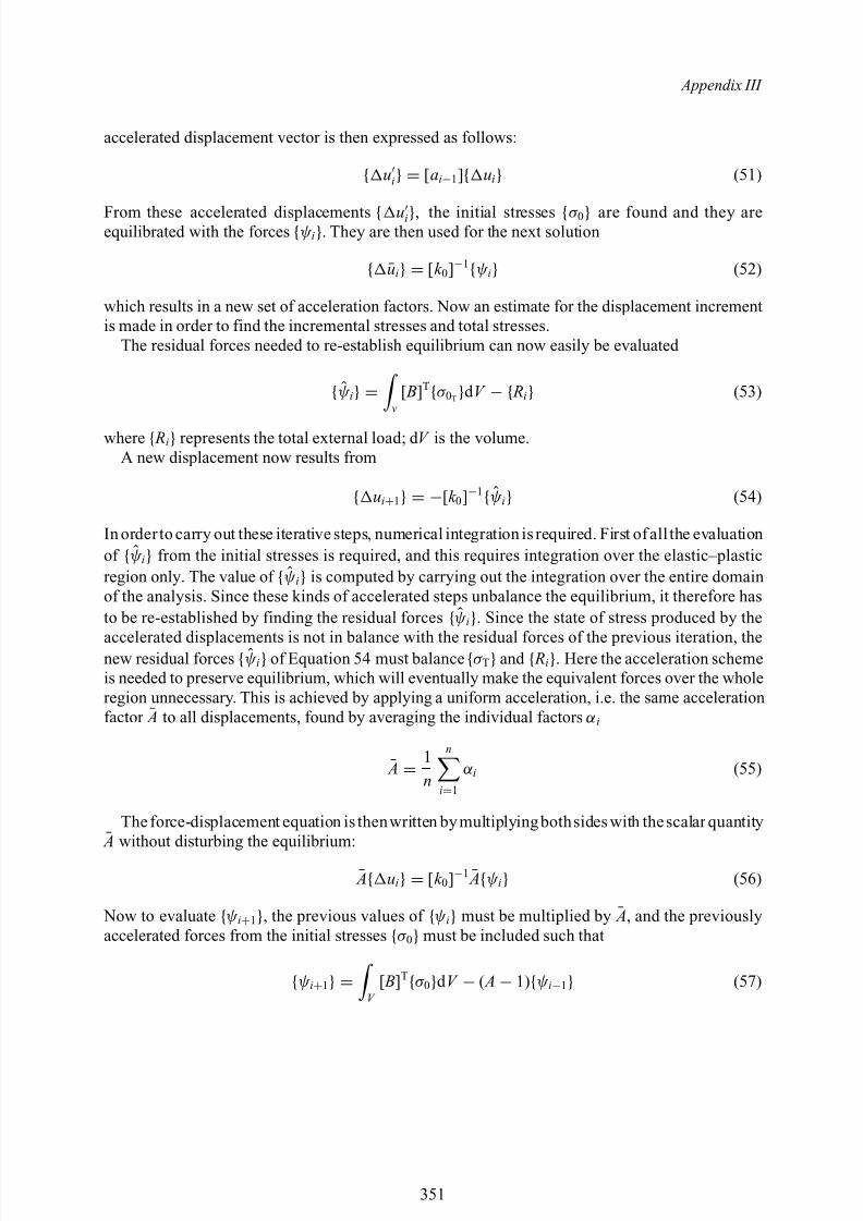
8/10/2019 Lifts Elevators Escalators and Moving Walkways Travelators 2DE2
http://slidepdf.com/reader/full/lifts-elevators-escalators-and-moving-walkways-travelators-2de2 162/169
Appendix III
accelerated displacement vector is then expressed as follows:
{ ui} = [a i−1]{ ui} (51)
From these accelerated displacements { ui}, the initial stresses {σ 0} are found and they areequilibrated with the forces {ψ i}. They are then used for the next solution
{ ¯ui} = [k 0]−1{ψ i} (52)
which results in a new set of acceleration factors. Now an estimate for the displacement incrementis made in order to find the incremental stresses and total stresses.
The residual forces needed to re-establish equilibrium can now easily be evaluated
{ψ i} = v[ B]T{σ 0T}d V − { Ri} (53)
where { Ri} represents the total external load; d V is the volume.A new displacement now results from
{ ui+1} = −[k 0]−1{ψ i} (54)
In order to carry out these iterative steps, numerical integration is required. First of all the evaluationof {ψ i} from the initial stresses is required, and this requires integration over the elastic–plasticregion only. The value of {ψ i} is computed by carrying out the integration over the entire domainof the analysis. Since these kinds of accelerated steps unbalance the equilibrium, it therefore hasto be re-established by finding the residual forces {ψ i}. Since the state of stress produced by the
accelerated displacements is not in balance with the residual forces of the previous iteration, thenew residual forces {ψ i} of Equation 54 must balance {σ T} and { Ri}. Here the acceleration schemeis needed to preserve equilibrium, which will eventually make the equivalent forces over the wholeregion unnecessary. This is achieved by applying a uniform acceleration, i.e. the same accelerationfactor ¯ A to all displacements, found by averaging the individual factors α i
¯ A = 1n
n
i=1
α i (55)
The force-displacement equation is thenwritten by multiplyingbothsides with thescalar quantity
¯ A without disturbing the equilibrium:
¯ A{ ui} = [k 0]−1 ¯ A{ψ i} (56)
Now to evaluate {ψ i+1}, the previous values of {ψ i} must be multiplied by ¯ A, and the previouslyaccelerated forces from the initial stresses {σ 0} must be included such that
{ψ i+1} = V [ B]T{σ 0}d V − ( A − 1){ψ i−1} (57)
351

8/10/2019 Lifts Elevators Escalators and Moving Walkways Travelators 2DE2
http://slidepdf.com/reader/full/lifts-elevators-escalators-and-moving-walkways-travelators-2de2 163/169
Appendix III
Relevant computer programs for the finite element analysis
Abstracts from main program ISOPAR based on finite element analysis
352
8/10/2019 Lifts Elevators Escalators and Moving Walkways Travelators 2DE2
http://slidepdf.com/reader/full/lifts-elevators-escalators-and-moving-walkways-travelators-2de2 164/169
Additional References/Bibliography
1. BSI. Safety Rules for the Construction and Installation of Escalators and Passenger Conveyors . BSEN 115: 1995.
2. Private Communications on Elevators , OTIS CO. London 2001.3. Private Communications on Elevators , Shindler Elevator and Escalator. Co. Vienna. Austria 2002.4. Private Communications on Elevators and Escalators , Fujitec CO. Japan, 2002.5. Corus. Special Profiles on Elevator Guide Rail Systems , West Bromwich, U.K. 2002.6. Barney G.C.: Remote Monitoring of Lifts, Escalators and Passenger Conveyors . Int. Nat. Assn. of
Elevator Engins.* 1990.7. Strakosch G.R.: Strakosch.Vertical Transportation-Elevators and Escalators . Wiley and Sons 1968.8. ASME. Inspectors Manual for Electric Elevators. A17.2.1, ASME 1996.9. ASME. Safety Codes for Elevators and Escalators. A17.1, ASME, 1996.
10. ASME. Check List for Inspection of Hydraulic Elevators. A17.2.2, ASME 1998.11. ASME. Check List for Inspection and Test of Electric Elevators . A17.2.1, ASME, 1994.12. ASME. Handbook on Safety Code for Elevators and Escalators . A17.1, ASME, 1996.13. Aberkrom, P.: Results of Experimental Work on Traction Drives . Elevator Technology 4. Proceedings of
ELEVCON 92, Amsterdam, 1992.14. Cholewa, W. and Hansel, J.: Problem of Plastic Lining Application in Friction Drives . Elevator
Technology 4. Proceedings of ELEVCON 86, Nice, 1986.15. de Crouy-Chanel, F.: International Standardization in the Lift Industry . Elevator Technology 4.
Proceedings of ELEVCON 86, Nice, 1986.16. Deimann, R.: Experience with Rope Brakes. Elevator Technology 4. Proceedings of ELEVCON 92,
Amsterdam, 1992.17. Distaso, C.: Polyurethane Buffers. Elevator Technology 3. Proceedings of ELEVCON 90, Rome, 1990.18. Feyrer, K.: Discard Criteria for Wire Ropes . Elevator Technology 2. Proceedings of ELEVCON 88,
Karlsruhe, 1988.19. Franzen, C.F. and Englert, Th.: Der Aufzugbau . F. Vieweg & Sohn, Braunschweig, 1972.20. Gibson, G.W.: New Concepts in Traction Drives . Proceedings of the International Lift Symposium,
Amsterdam, 1984.21. Gibson, G.W.: Kinetic Energy of Passenger Elevator Door Systems. ELEVATOR WORLD 12/1989 and
1/1990, Mobile, USA.22. Hymans, F. and Hellborn, A.V.: Der neuzeitliche Aufzug mit Treibscheibenatrieb. Julius Springer, Berlin,
1927.23. Janovský, L.: Elevator Mechanical Design . Ellis Horwood Ltd., Chichester, 1987.24. Janovský, L.: Stress Analysis in Guide Rails of Electric Elevators . Technical University of Prague,
dissertation, 1981.25. Janovský, L.: The Distribution of Tensile Forces in Elevator Ropes with Traction Drives and the Resultant
Effect upon Wear of Sheave Grooves . Proceedings of the International Lift Symposium, Amsterdam,1984.
26. Janovský, L.: Testing of Elevator Machines. Proceedings of ELEVCON 88, Karlsruhe, 1988.27. Janovský, L.: Worldwide Standards for Guide Rail Calculations. Elevator Technology 4. Proceedings of
ELEVCON 92, Amsterdam, 1992.28. Janovský, L. and Doležal. J.: Výtahy a eskalátory. SNTL, Prague, 1980.29. Kamaike H., Ishii, T., Watanabe, E., Matsukura, Y.: A Ropeless Linear Drive Elevator. ELEVATOR
WORLD 3/1991, Mobile, USA.30. Kampers, P.: TheBest Elevator Rope. ElevatorTechnology 4. Proceedings of ELEVCON 92, Amsterdam,1992.
31. Laney, R. and McCallum, W.: Whisperflex Compensating Cable . Elevator Technology 4. Proceedings of ELEVCON 86, Nice, 1986.
32. Measuring Sound. Brochure of Bruel & Kjaer, Denmark, 1984.
353

8/10/2019 Lifts Elevators Escalators and Moving Walkways Travelators 2DE2
http://slidepdf.com/reader/full/lifts-elevators-escalators-and-moving-walkways-travelators-2de2 165/169
Lifts, Elevators, Escalators and Moving Walkways/Travelators
33. Nederbragt, J.A.: Emergency Rope Brake . ELEVATOR WORLD 5/1985, Mobile, USA.34. Nederbragt, J.A.: Rope Brake as Precaution against Overspeed . ELEVATOR WORLD 7/1989,
Mobile, USA.35. Niemann, G. and Winter, H.: Maschinenelemente III . Springer Verlag, Berlin, 1983.
36. Phillips, R.S.: Electric Lifts. Pitman Publishing, London, 1973.37. Strakosch, G.: Vertical Transportation: Elevators and Escalators . 2nd Edition. John Wiley & Sons, NewYork, 1983.
38. Sturgeon, W.C.: The LIM Elevator Drive . ELEVATOR WORLD 3/1991, Mobile, USA.39. Terminology for Lifts, Escalators and Passenger Conveyors . Federation Europeenne de la Manutention,
Section VII, 1981.40. TheSelection and Inspection of Elevator Ropes. ELEVATOR WORLDEducation Package, Mobile, USA.41. Walker, H.: The Thermal Rating of Worm Gearboxes.42. ANSI/AGMA6034-A87, Practice for Enclosed Cylindrical Wormgear Speed Reducers and Gearmotors ,
March, 1988.43. Australian Standard AS 2759-1985, Steel Wire Rope – Application Guide.44. Australian Standard AS 3569-1989, Steel Wire Ropes .
45. BS 5655: Part 1: 1979/EN 81: Part 1, Lifts and Service Lifts. Safety Rules for the Construction and Installation of Electric Lifts.46. BS 5655: Part 5: 1981, Lifts and Service Lifts. Specification for Dimensions of Standard Electric Lifts
Arrangements.47. BS 5655: Part 9: 1985, Lifts and Service Lifts. Specification for Guide Rails .48. ISO 4344. Steel Wire Ropes for Lifts.
354

8/10/2019 Lifts Elevators Escalators and Moving Walkways Travelators 2DE2
http://slidepdf.com/reader/full/lifts-elevators-escalators-and-moving-walkways-travelators-2de2 166/169
Subject Index
AAccessibility, 112Accidents, 34Actual effort, 159Actual load, 159, 269, 270, 271Adjustable shackle rods, 52American National Standard, 162American practice, 51, 62, 250, 252American standard safety code, 186Angle of inclination, 103, 107, 113Anti-rotation devices, 54
Anti-slide device, 106ASME formulae, 62Authorised and instructed user, 3Autowalk, 217, 219, 221Auxiliary rope-fastening devices, 54Available car area, 3
BBabbitt metal, 53Balustrade, 81, 82, 84, 103, 104, 105, 106,
110, 121, 219Beams, 237, 238, 242
Belt, 107, 108, 133Belt calculations, 201Belt capacity, 201Belt drive, 133, 135Belt length, 137, 138Bending moment, 13, 177, 178Brake, 116Brake and braking systems, 164Brake monitors, 164Braking system, 113Braking torque, 10, 166, 170Bridon Ropes Ltd, 149
British practice, 251Broken Drive Chain Switch, 127Buckling factor, 10, 13, 34, 35, 176, 187Buckling stresses, 9, 38, 39Buffer, 3, 37, 38, 186Buffer engagement, 63, 190Buffer reaction, 72Buffer strokes, 11, 34, 188Buffer supports, 72Bumpers, 55, 60
C
Canopy details, 31Captive roller, 38Car buffers, 55, 60Car frame, 35, 60, 169, 190Car frame plank, 63Car frame uprights, 63, 70
Car guide, 169Centrifugal tension, 142Chains, 49Characteristic fire load density, 224, 226Characteristic fire loads, 224Clearances, 40, 45, 56, 109Closed cylinder and plunger heads, 59Column-water interaction, 247Comb, 107, 109Combplates, 104, 128Compensating ropes, 46, 52
Compensation, 46, 49Compound belt drive, 134, 135Compression members, 238Cone diameter, 138Continuous rubber belt, 217, 219CORUS, 175, 176Counterweight, 31, 35, 37, 60, 168, 169, 182, 199Counterweight buffers, 60Counterweight details, 31Counterweight safeties, 71Crossed drive, 138Cross-heads, 190
Cured resin, 53Cylinder, 56, 58, 59Cylinder design, 67Cylinder heads, 59, 68Cylinder packing heads, 59
DDC motor drives, 127Deck barricades, 106Definitions, 3Deflection, 17, 181, 128Deflection of joints, 277
Deflection of trusses, 272Deflector device, 107Deformation, 17, 22, 46, 208, 209, 274Design, 21, 56, 59Design analysis, 149Design estimate, 21Design specifications, 21, 81Direct-plunger hydraulic elevators, 55, 61Disconnected motor safety device, 127Diversion, 46Door, 194Door closing time, 195
Door closure force, 194Door dynamics, 194Door weight, 195Drivers, 133, 136Drives and traction, 153, 154Driving machine, 61, 112
355
8/10/2019 Lifts Elevators Escalators and Moving Walkways Travelators 2DE2
http://slidepdf.com/reader/full/lifts-elevators-escalators-and-moving-walkways-travelators-2de2 167/169
Subject Index
Drums, 49, 217Dyform elevator ropes, 149
E
Eccentric loading, 67Electric lifts, 3, 33Elevator machines, 159Elevator rope data, 146, 149Elevator traffic, 198Emergency, 73Emergency doors, 36, 37Emergency stopping, 121Energy accumulation buffers, 186Energy dissipation buffers, 188Escalator, 81, 104European practice, 254
European Standard, 81, 150
FFinal limit switches, 37Fin-edge plates, 207Finite element analysis, 118, 201Fire, 36, 73, 222Fire analysis, 217Fire density, 229Flame, 76Flange, 204, 205Flexibility method of analysis, 271
Followers, 133, 136Forces, 39, 181, 267Freight elevator platform, 65Fujitec, 81, 97, 217
GGeared elevator machines, 159, 161General specifications, 104Girder truss load, 277Goods passenger lift, 3Governor tripping speed, 72, 199Grooved pulley, 144, 145
Guards, 106Guide rail, 171, 175, 179, 183Guide, 3, 37, 169Guide shoes, 32, 182
HHandrail, 104, 117, 127Hardened Elevators, 76Headroom, 40, 43Heat, 76, 235Heat transfer analyses, 242Heaters, 127
Hollow columns, 246Horizontally sliding doors, 46, 194Horse power, 141, 201Hospitals, 21Hotels, 21H.P. calculations, 143
Hydraulic elevator arrangements, 32Hydraulic lift, 3, 55Hydraulic lift data, 29, 30Hydraulic machines, 66
IIdeal effort, 159Ideal load, 159Inspection, 119, 121, 127, 128Inspection doors, 37, 112Instantaneous safety gear, 3, 12, 38, 39, 174, 185Instantaneous safety gear with buffed effect, 4Interior low deck, 107Involute teeth, 202, 208
J
Jack (Heber), 4, 7Jeane’s graph, 242, 250Joint deflection, 275
K Kone, 42, 217
LLanding depth, 40, 45Landing doors, 45Landing entrance, 46Levelling, 4
Lie’s graph, 243, 250Lift, 4, 197Lift car, 4, 35, 45Lift machine, 4, 46Lift wells, 35Lighting, 111, 121, 128Limiting temperature criterion, 238Limits of speed, 62Linear speed, 134, 142Load-carrying capacity, 238Loading and restraints, 223
MMachine, 41, 85, 87, 88Machine room, 4, 45Machine room dimensions, 41, 45Machinery, 62, 118Machinery spaces, 111, 112Malhotra’s method, 250Maximum allowable stresses, 61Maximum bending moments, 269Maximum stresses, 61, 71Mechanical advantage, 158, 159Mechanical strength, 46, 105
Minimum breaking load, 4, 49, 152Minimum rated load, passenger elevators, 62Missing step or pallet device, 127Modules of elasticity of steel, 237Moment of inertia, 65, 71Moving walkways, 81, 104
356

8/10/2019 Lifts Elevators Escalators and Moving Walkways Travelators 2DE2
http://slidepdf.com/reader/full/lifts-elevators-escalators-and-moving-walkways-travelators-2de2 168/169
Subject Index
N Newel, 105, 106, 111 Non commercial vehicle lift, 5 Non-return valve, 5
OOne-way restrictor, 5Open drive, 137OTIS, 81, 116, 197, 217Overspeed governor ropes, 49Overspeed governors, 5, 41, 49
PPallets, 107, 108, 109, 113Panoramic view, 4, 28Passenger, 5Passenger conveyor, 3, 104Passenger conveyor data, 219Pawl device, 6, 40Pipe design, 69Piping, 66Pit, 5, 40, 43Platforms, 60, 202Plunger, 55, 59Plunger connection, 59Plunger design, 59, 66Plunger heads, 68Plunger joints, 60Pneumatic lifts, 3Polyurithane buffers, 189Positive drive lift (includes drum drive), 6, 38Positive drive service lift (includes drum drive), 6Power, 77, 201Power elevators, 72Power transmission, 139Pressure, 151Pressure in ropes, 150Pressure relief valve, 6Pressurization systems, 76Progressive safety gear, 6, 174Pulley room, 6, 41Pulleys, 41, 46
R Rated load, 6, 116Rated speed, 7, 107Redundant bars, 267, 268Reeving, 46Reeving ratio, 7Re-levelling, 7, 152Residential houses and apartments, 21Residential lift, 45Restrictor, 6
Reversal Stop Switch, 127Roller guides, 182Rope, 49, 145Rope drive, 133, 144Rope elongation, 152Rope fastenings, 52
Rope riding, 144Rope termination, 150Roped hydraulic elevators, 55, 61Round Trip Time, 197
Routine inspection, 121Rubber belt passenger conveyor, 217
SSafeguard, 35Safety bulkhead, 56Safety factor, 49, 51, 69, 72, 149, 152, 227Safety gear, 7, 49Safety gear operation, 39, 174Safety rope, 7Safety space, 43Schindler, 81, 217
Seat, 205Semicircular grooves, 50Service lift, 7Shear forces, 269Shear plate, 202, 204Shut-off valve, 7Single acting jack (Heber), 7Single panel side opening (SPSO), 195Skirt panels, 106, 121Skirting, 104, 109Slenderness ratio, 65, 71Sling, 7
Smoke, 76, 77Specific pressure, 151Sprockets, 46, 164Steel columns, 246Steel in escalators, 235Step, 107, 116Step or pallet level device, 127Step upthrust device, 127Stiles, 63, 70Stopping distances, 71, 199Strokes, 36, 188Structural analysis, 117
Structural strength, 46Super structures, 201Supporting box chamber, 280Supporting columns, 83Supporting girder, 279Supporting trusses, 83Suspension, 49Suspension ropes, 51, 151Suspension wire ropes, 72, 150Symbols, 7, 103
T
Tall buildings, 73, 75Tandem operation, 127Tapered rope sockets, 52, 53Temperature course of fire, 230, 233Temperature–time relation, 229Tension members, 238
357

8/10/2019 Lifts Elevators Escalators and Moving Walkways Travelators 2DE2
http://slidepdf.com/reader/full/lifts-elevators-escalators-and-moving-walkways-travelators-2de2 169/169
Subject Index
Thermal performance, 163Thermosetting resin composition, 53Toe guard, 7, 190Traction, 50, 153
Traction and pressure, 156Traction drive lift, 7Traction drive service lift, 7Transmission of power, 139Trap doors, 46, 112Travel analysis, 197Travelators, 104, 217Treadways, 120Truss deflection, 275Trusses, 85, 265Trusses supporting travelators, 265
UUndercut grooves, 50, 156Unlocking zone, 7, 27Unprotected steel columns, 247Unprotected steel members, 239
Up-peak handling capacity, 197Up-peak interval, 197User, 7
VValve, 56, 62Velocity ratio, 133, 135, 158Vertical force, 40, 46, 105
WWalking platform, 202, 204Walkways, 217, 219Water, 77Waviness, 209Well, 7Williot-Mohr diagram, 265
World Trade Center, 77Worm diameter, 162Worm gear drives, 162Worm thread surfaces, 160