Lifting equipment Contents - Giovenzana International B.V.€¦ · 11 Lifting equipment Contents...
15
-
Upload
trankhuong -
Category
Documents
-
view
216 -
download
0
Transcript of Lifting equipment Contents - Giovenzana International B.V.€¦ · 11 Lifting equipment Contents...

11
Lifting equipment Contents
LIF
TIN
G E
QU
IPM
EN
T
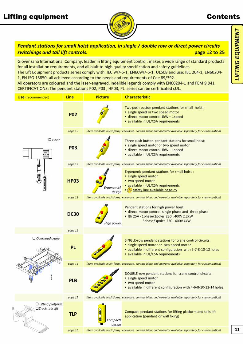
Pendant stations for small hoist application, in single / double row or direct power circuits
switchings and tail lift controls. page 12 to 25
Giovenzana International Company, leader in lifting equipment control, makes a wide range of standard products for all installation requirements, and all biult to high quality specification and safety guidelines.The Lift Equipment products series comply with: IEC 947-5-1, EN60947-5-1, UL508 and use: IEC 204-1, EN60204-1, EN ISO 13850, all achieved according to the needs and requirements of Cee 89/392.All operators are coloured and the laser-engraved, indelible legends comply with EN60204-1 and FEM 9.941.CERTIFICATIONS: The pendant stations P02, P03 , HP03, PL series can be certificated cUL.
Use (recommended) Line Picture Characteristic
P02Two push button pendant stations for small hoist :• single speed or two speed motor• direct motor control 1kW – 1speed• available in UL/CSA requirements
page 12 (item available in kit-form,: enclosure, contact block and operator available separately for customization)
P03Three push button pendant stations for small hoist:• single speed motor or two speed motor• direct motor control 1kW – 1speed• available in UL/CSA requirements
page 12 (item available in kit-form,: enclosure, contact block and operator available separately for customization)
HP03
Ergonomic pendant stations for small hoist :• single speed motor• two speed motor• available in UL/CSA requirements• safety line available page 25
page 12 (item available in kit-form,: enclosure, contact block and operator available separately for customization)
DC30Pendant stations for high power hoist:• direct motor control single phase and three phase• Ith 25A - 1phase/2poles 230…400V 2.2kW
3phase/3poles 230…400V 4kW
page 12
PLSINGLE-row pendant stations for crane control circuits:• single speed motor or two-speed motor• available in different configuration with 5-7-8-10-12 holes• available in UL/CSA requirements
page 14 (item available in kit-form,: enclosure, contact block and operator available separately for customization)
PLBDOUBLE-row pendant stations for crane control circuits:• single speed motor• two speed motor• available in different configuration with 4-6-8-10-12-14 holes
page 15 (item available in kit-form,: enclosure, contact block and operator available separately for customization)
TLP Compact pendant stations for lifting platform and tails lift application (pendant or wall fixing)
page 16 (item available in kit-form,: enclosure, contact block and operator available separately for customization)
High power!
Compact!
design
� Hoist
� Overhead crane
� Lifting platform
�Truck tails lift
Ergonomic!
design

12
230
LAYOUT CONFIGURATION
250
250
TWO SPEED
SINGLE SPEED(* TILTING BUTTON16A – 250Vac ½ HP)
SINGLE SPEED
230
250
230
(*) HIGH POWER CONTACTSDIRECT MOTOR CONTROL
1Kw 1ph
460
450
460SINGLE SPEED
TWO SPEED 460
PICTURE
330SINGLE SPEED
TWO SPEED 350
600
600
600
SINGLE SPEED
CODE
P02.1
P02.2
P02.4
P02.CD
P02.RM
P02.D2
P03CD
P03.2
P03.3
P03D2
HP03.D2
HP03
DC30
DC30.GE
DC30D2 650
CONTACT TYPE
TWO SPEED
3 NO1 NC
3 NO1 NC
2 NO2 NC
2 NO2 NC
(*) Ith 25A EXTRA HIGH POWERCONTACTS BLOCK FOR
DIRECT MOTOR CONTROL :2.2kW 1ph / 4kW 3ph
(*) Ith 25A EXTRA HIGH POWERCONTACTS BLOCK FOR
DIRECT MOTOR CONTROL :2.2kW 1ph / 4kW 3ph
(*) HIGH POWER CONTACTSDIRECT MOTOR CONTROL
1Kw 1ph
3 NO1 NC
3 NO1 NC (*)
4 NO 4 NO (*)
(*)
(*)
P02
P03
HP03
DC30
Pendant stations Hoist control: P02 P03 HP03 DC30
1 NO* 1 NO*
I^
II^
440P03.1
I^
II^
I^
II^
(*) (*)
(*) (*)
(*) (*)
(*) (*)
(*) (*)
(*) (*)
(*)
(*)
(*)
LIF
TIN
G E
QU
IPM
EN
T
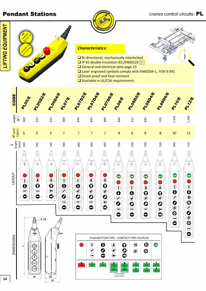
Characteristics:
� Bi-directional, mechanically interlocked� IP 65 double insulation IEC/EN60529� General and electrical data page 23� Laser engraved symbols comply with EN60204-1, FEM 9.941� Shock proof and heat resistant
WEIGHT[gr]
DC30.RG

13
P02
P03
HP03
DC30
Pendant stations Dimensions: P02 P03 HP03 DC30
LIF
TIN
G E
QU
IPM
EN
T
14
Pendant Stationsw
eigh
t[g
r.]
CO
DE
LAYO
UT
600
655
625
800
880
915
945
970
1.10
5
1.29
0
830
855
890
DIM
ENSI
ON
S
5 55 7 7 8 8 8 10 127 7 8
N°p
ush
butt
oncranes control circuits: PL
345
345
345
495
495
530
530
530
640
710L
leng
ht[m
m]
495
495
530
LIF
TIN
G E
QU
IPM
EN
T
NC NO NO
(*) two speedcontact block
NO
NO
NO
NO NO NO
NO NO
NO
PUSH BUTTON TYPE – CONTACT TYPE COUPLED
Characteristics:
� Bi-directional, mechanically interlocked� IP 65 double insulation IEC/EN60529� General and electrical data page 23� Laser engraved symbols comply with EN60204-1, FEM 9.941� Shock proof and heat resistant� Available in UL/CSA requirements
NO

15
wei
ght
[gr.
]C
OD
ELA
YOU
T
530
700
555
860
920
945
1.08
0
1.24
5
1.44
5
730
755
895
4 64 6 8 8 8 10 12 146 8
N°p
ush
butt
onD
IMEN
SIO
NS
345
399
345
453
453
453
547
604
655
399
399
453L
leng
ht[m
m]
Pendant Stations cranes control circuits: PLB
LIF
TIN
G E
QU
IPM
EN
T
Characteristics:
� Bi-directional, mechanically interlocked� IP 65 double insulation IEC/EN60529� General and electrical data page 23� Laser engraved symbols comply with EN60204-1, FEM 9.941� Shock proof and heat resistant
NC NO NO
(*) two speedcontact block
NO
NO
NO
NO NO NO
NO NO
NO
TIPO DI PULSANTE – TIPO DI CONTATTO ABBINATO
NO
NO

MOBILE-PENDANT FIXING (with WALL BRACKET accessories)
16
wei
ght
[gr.
]C
OD
ELA
YOU
TN
°pus
hbu
tton
DIM
ENSI
ON
S
120
1
80
200
2
115
120
1
80
314
4
185
255
3
150
255
3
150
314
4
185L
leng
ht[m
m]
LIF
TIN
G E
QU
IPM
EN
T
Lifting platform – Truck tail lift: TLPPendant / Fixed Stations
push pull twist release
selector switch
NC NO NO
PUSH BUTTON TYPE CONTACT TYPE COUPLED
NO
L
WithEmergency Stop
WithSelector Switch
WALL FIXING
Characteristics:
� Compact and modern design� Bi-directional, mechanically interlocked� IP 65 double insulation IEC/EN60529� General and electrical data page 23� Laser engraved symbols comply with EN60204-1, FEM 9.941� Contact block with spring cage terminal� Shock proof and heat resistant� Mobile-Pendant (with wall bracket accessories) or wall fixed mounting
selector switch

Pendant / Fixed Stations
17
Contact Block type: PL004 - PCW
LIF
TIN
G E
QU
IPM
EN
T
SimplyContact
Point
P02
PL004 lineDC30
(e-stop only)P03 PLBPL
NC
PL004001
N0
PL004002
Clamping screw M3.5 terminal with mobile “bent tile” plate that works with cables of different section
Dimensions
HP03
PCW lineTLP
MarkingsThreeContact Point
safe & durableenergy transmission
NC
PCW01
N0
PCW10
Spring cage terminal with two separated platesthat works with cables with different section
Dimensions
1) Insert the screwdriver2) turn 1/4 the screwdriver3) insert wire 4) remove the screwdriver
Spring cage terminal:
Markings
Technical data see page 23

18
Pendant / Fixed Stations KIT To be customizedCreate your customized station in 4 steps
CODE
WEIGHT[gr]
HOLESn°
2
3
5
7
8
10
12
4
6
8
10
12
14
1
2
3
4
700
710
810
910
800
STEP 1Choose station
type
LIF
TIN
G E
QU
IPM
EN
T
SMALL DIMENSIONS BIG
P02
P03
PL
PLB
TLP
P02K
P03K
PL05K
PL07K
PL08K
PL10K
PL12K
PLB04K
PLB06K
PLB08K
PLB10K
PLB12K
PLB14K
TLP1K
TLP2K
TLP3K
TLP4K
180
258
410
540
600
410
510
610
100
130
160
200

19
Pendant / Fixed Stations
P02-P03-PL-PLB
NC NO NC NO
TLP
STEP 2Choose OPERATOR
NOT for TLP
KIT To be customizedCreate your customized station in 4 steps
(*) Symbols according to FEM 9.941Customized engraving available (min. quantity applies)
(*)
colore?
(*)
LIF
TIN
G E
QU
IPM
EN
T
STEP 3Choose CONTACT TYPE

20
Pendant / Fixed Stations KIT To be customizedCreate your customized station in 4 steps
LIF
TIN
G E
QU
IPM
EN
T
TLPP03
P02
STEP 4Mounting
instructions

21
Pendant / Fixed Stations KIT To be customizedCreate your customized station in 4 steps
LIF
TIN
G E
QU
IPM
EN
T
1° sp. 2° sp.
PL
PLB
2° speed“low” plunger
1° speed“high” plunger

22
Pendant / Fixed Stations Spare Parts / Accessories
SPARE PARTS:
NOT for TLPNOT for TLP
P02 – P03 – PL – PLB – TLP
� Operators and contacts block codes please go to page 19
TLP ACCESSORIES
LIF
TIN
G E
QU
IPM
EN
T
DC30
mechanical interlock
1…3
416000061
1600006212901054
WALL BRACKET SPIRAL CABLE GLAND
DRAWINGS EXAMPLES
CONTACT BLOCKS RUBBER BUTTON COVER

Pendant / Fixed Stations General and Electrical data
LIF
TIN
G E
QU
IPM
EN
T
23
Electrical characteristicscontact blocks
P02 – P03 – HP03 – PL – PLB – TLP DC30
Markings
Rated insulation voltage [Ui] 690V 500V
Rated thermal current [Ith] 16A 25A
Rated impulse withstand voltage [Uimp] 4kV 4kV
Frequency 50Hz – 50/60 Hz type PCW (HP03-TLP) 50Hz
Rated operating current [Ie]
AC-15alternate current
(V) 24 60 110 240 400 440 500 690
type: PL004..P02/P03/DC30 e-stop/PL/PLB
(A) 16 12 8 6 4 3.5 3 1 -
type: PCW..HP03-TLP
(A) 10 8 6 5 4 4 4 2 -
DC-13direct
current
(V) 24 48 60 110 220 250
type: PL004..P02/P03/DC30 e-stop/PL/PLB
(A) 2 1.2 0.85 0.4 0.25 - -
type: PCW..HP03-TLP
(A) 2 2 1 0.4 - 0.4 -
AC-3alternatecurrent
1phase-2poles 230V-400V - 2.2kW
3phase-3poles 230V-400V - 3kW
Conditional short circuit withstand current 1000A 1000A
Fuse rating gG 10A - 500V aM 12A - 500V
Contact insulation resistance ≤ 25mΩ -
Switchingmechanism
type: PL004..P02/P03/DC30 e-stop/PL/PLB
slow break double gap contactssingle pad slow break double gap contacts
single padtype: PCW..HP03-TLP
slow break double gap contactsthree pads
Positive operation NC contact block -
Terminal type
type: PL004..P02/P03/DC30 e-stop/PL/PLB
M3.5 screwM3.5 screw
type: PCW..HP03-TLP
spring cage terminal
Terminalcapactity
type: PL004..P02/P03/DC30 e-stop/PL/PLB
No. 1 or 2 flexible and solid conductor min 1 max 2.5 mm2
No. 1 or 2 flexible and solid conductor min 1 max 2.5 mm2type: PCW..
HP03-TLPNo. 1 or 2 flexible and solid conductor min 0.5 max 2.5 mm2
UL508 characteristics
General use 600V ac 16A -
Designation code (HD) Heavy Duty A600-Q600 -
General characteristics P02 – P03 – HP03 – PL – PLB – TLP DC30
In conformity to standards IEC / EN60947-5-1 IEC / EN60947-3
MaterialP02 P03 HP03 PL PLB TLP
ABSPP ABS ABS ABS ABS PP
Material group II II
Pollution class 3 3
Climatetemperature
operating -25°C + 70°C -25°C + 70°C
storage -30°C + 70°C -30°C + 70°C
Climate resistanceIEC68 part 2-3 hot damp hot damp
IEC68 part 2-30 unsettled hot damp unsettled hot damp
Cable entry� P02 – P03: rubber cable sleeve Ø7…18mm� PL – PLB: rubber cable sleeve Ø9…24mm� HP03: spiral cable gland M20 – TLP: cable gland M20
cable gland M25
Note: P02 – P03 – HP03 – PL line available in UL/CSA requirements