Gas Lift Design and Technology - downloads.oilprocessing.net
Upload
pane-ristovskiCategory
view
23download
1description
Tower - 3D Model Builder 7.0 Registered to Pane Ristovski 078225550 Radimpex - www.radimpex.rs
Contents Basic model properties ____________________________________________________________________________________________________________________________ 2 Input Data
Input data - Structure _____________________________________________________________________________________________________________________ 3 Input data - Load ________________________________________________________________________________________________________________________ 7
Results
Structural analysis _______________________________________________________________________________________________________________________ 9 Design (steel) _________________________________________________________________________________________________________________________ 12
Tower - 3D Model Builder 7.0 Registered to Pane Ristovski 078225550 Radimpex - www.radimpex.rs
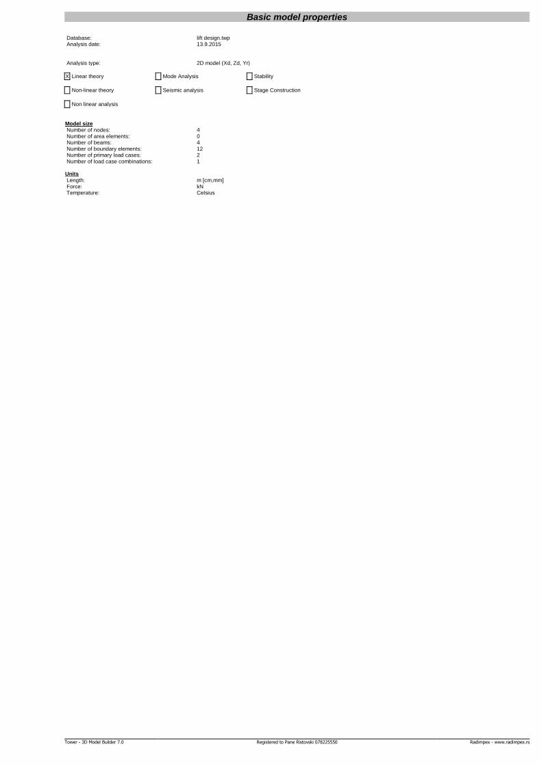
Basic model properties Database: lift design.twp Analysis date: 13.9.2015
Analysis type: 2D model (Xd, Zd, Yr)
X Linear theory Mode Analysis Stability
Non-linear theory Seismic analysis Stage Construction
Non linear analysis
Model size Number of nodes: 4 Number of area elements: 0 Number of beams: 4 Number of boundary elements: 12 Number of primary load cases: 2 Number of load case combinations: 1
Units Length: m [cm,mm] Force: kN Temperature: Celsius
Tower - 3D Model Builder 7.0 Registered to Pane Ristovski 078225550 Radimpex - www.radimpex.rs
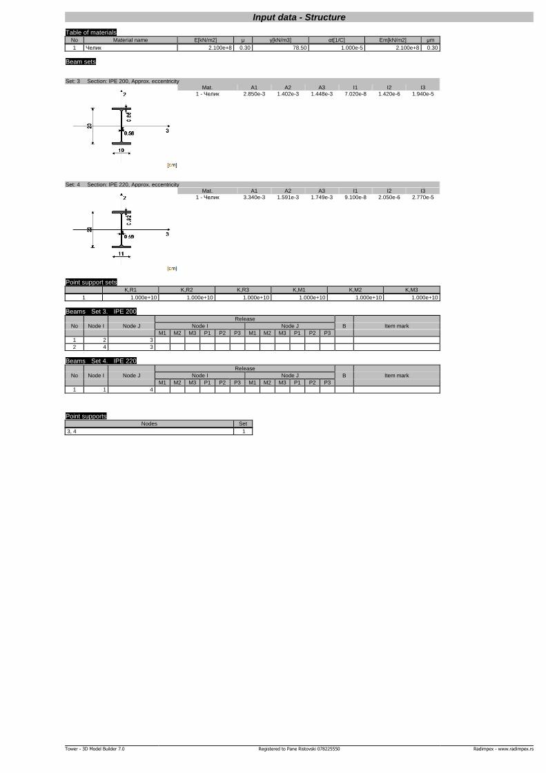
Input data - Structure
Table of materials No Material name E[kN/m2] μ γ[kN/m3] αt[1/C] Em[kN/m2] μm
1 Челик 2.100e+8 0.30 78.50 1.000e-5 2.100e+8 0.30
Beam sets Set: 3 Section: IPE 200, Approx. eccentricity
Mat. A1 A2 A3 I1 I2 I3 1 - Челик 2.850e-3 1.402e-3 1.448e-3 7.020e-8 1.420e-6 1.940e-5
Set: 4 Section: IPE 220, Approx. eccentricity
Mat. A1 A2 A3 I1 I2 I3 1 - Челик 3.340e-3 1.591e-3 1.749e-3 9.100e-8 2.050e-6 2.770e-5
Point support sets K,R1 K,R2 K,R3 K,M1 K,M2 K,M3
1 1.000e+10 1.000e+10 1.000e+10 1.000e+10 1.000e+10 1.000e+10
Beams Set 3. IPE 200 Release
No Node I Node J Node I Node J B Item mark
M1 M2 M3 P1 P2 P3 M1 M2 M3 P1 P2 P3
1 2 3
2 4 3
Beams Set 4. IPE 220 Release
No Node I Node J Node I Node J B Item mark
M1 M2 M3 P1 P2 P3 M1 M2 M3 P1 P2 P3
1 1 4
Point supports Nodes Set
3, 4 1
Tower - 3D Model Builder 7.0 Registered to Pane Ristovski 078225550 Radimpex - www.radimpex.rs
Rx1
Frame disposition
Tower - 3D Model Builder 7.0 Registered to Pane Ristovski 078225550 Radimpex - www.radimpex.rs
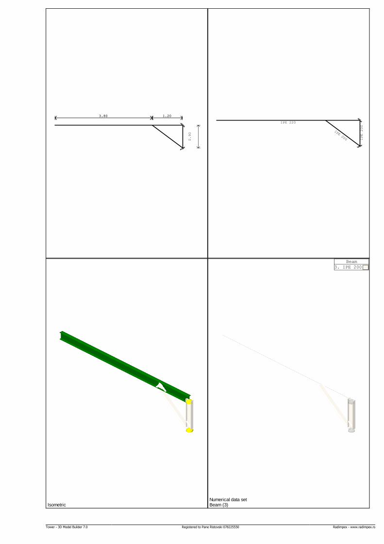
3.80 1.20
0.90
3.80 1.20
IPE 220
IPE 200 IPE 200
Isometric
Beam
3. IPE 200
Beam (3) Numerical data set
Tower - 3D Model Builder 7.0 Registered to Pane Ristovski 078225550 Radimpex - www.radimpex.rs
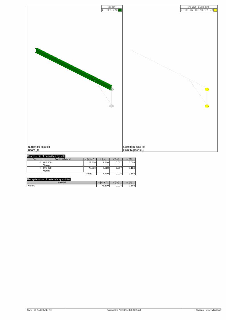
Beam
4. IPE 220
Beam (4) Numerical data set
Point Support
1. R1 R2 R3 М1 М2 М3
Point Support (1) Numerical data set
Beams - bill of quantities by sets Set Section/Material γ [kN/m³] L [m] V [m³] m [T]
3 IPE 200 78.500 2.400 0.007 0.055 Челик
4 IPE 220 78.500 5.000 0.017 0.134 Челик
Total: 7.400 0.024 0.188
Recapitulation of materials quantities Material γ [kN/m³] V [m³] m [T]
Челик 78.500 0.024 0.188
Tower - 3D Model Builder 7.0 Registered to Pane Ristovski 078225550 Radimpex - www.radimpex.rs
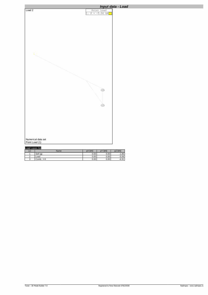
Input data - Load Point Load
1. P = -5.06 kN
Load 2
Point Load (1) Numerical data set
Load cases list LC Name pX [kN] pY [kN] pZ [kN]
1 Self (g) 0.00 0.00 -1.85
2 Load 0.00 0.00 -5.06
3 Comb.: I+II 0.00 0.00 -6.91
Tower - 3D Model Builder 7.0 Registered to Pane Ristovski 078225550 Radimpex - www.radimpex.rs
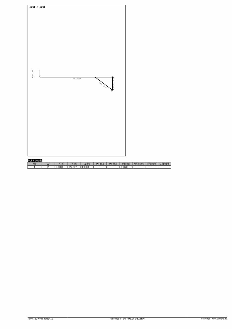
IPE 220
IPE 200 IPE 200
P=5.06
Load 2: Load
Point Loads No LC X [m] Y [m] Z [m] Px [kN] Py [kN] Pz [kN] Mx [kNm] My [kNm] Mz [kNm]
1 2 0.0000 -27.707 0.9000 -5.0600
Tower - 3D Model Builder 7.0 Registered to Pane Ristovski 078225550 Radimpex - www.radimpex.rs
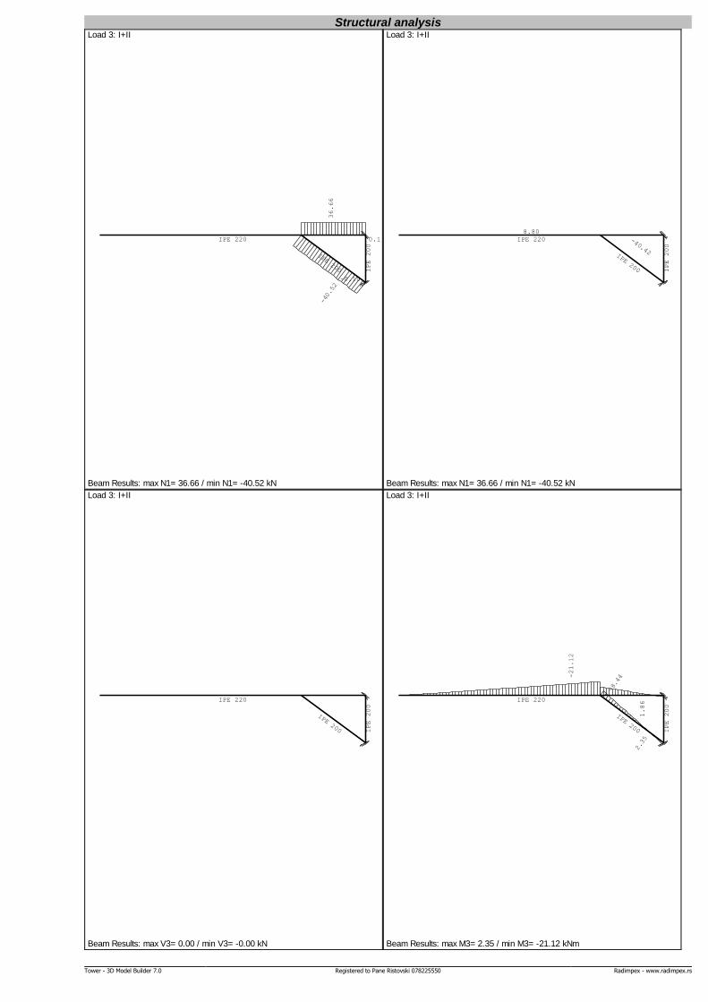
Structural analysis
IPE 220
IPE 200 IPE 200
0.10
-0.10
-40.52
36.66
Load 3: I+II
Beam Results: max N1= 36.66 / min N1= -40.52 kN
IPE 220
IPE 200 IPE 200
-40.42
8.80
Load 3: I+II
Beam Results: max N1= 36.66 / min N1= -40.52 kN
IPE 220
IPE 200 IPE 200
Load 3: I+II
Beam Results: max V3= 0.00 / min V3= -0.00 kN
IPE 220
IPE 200 IPE 200
-8.44
2.35
-21.12
1.86
Load 3: I+II
Beam Results: max M3= 2.35 / min M3= -21.12 kNm
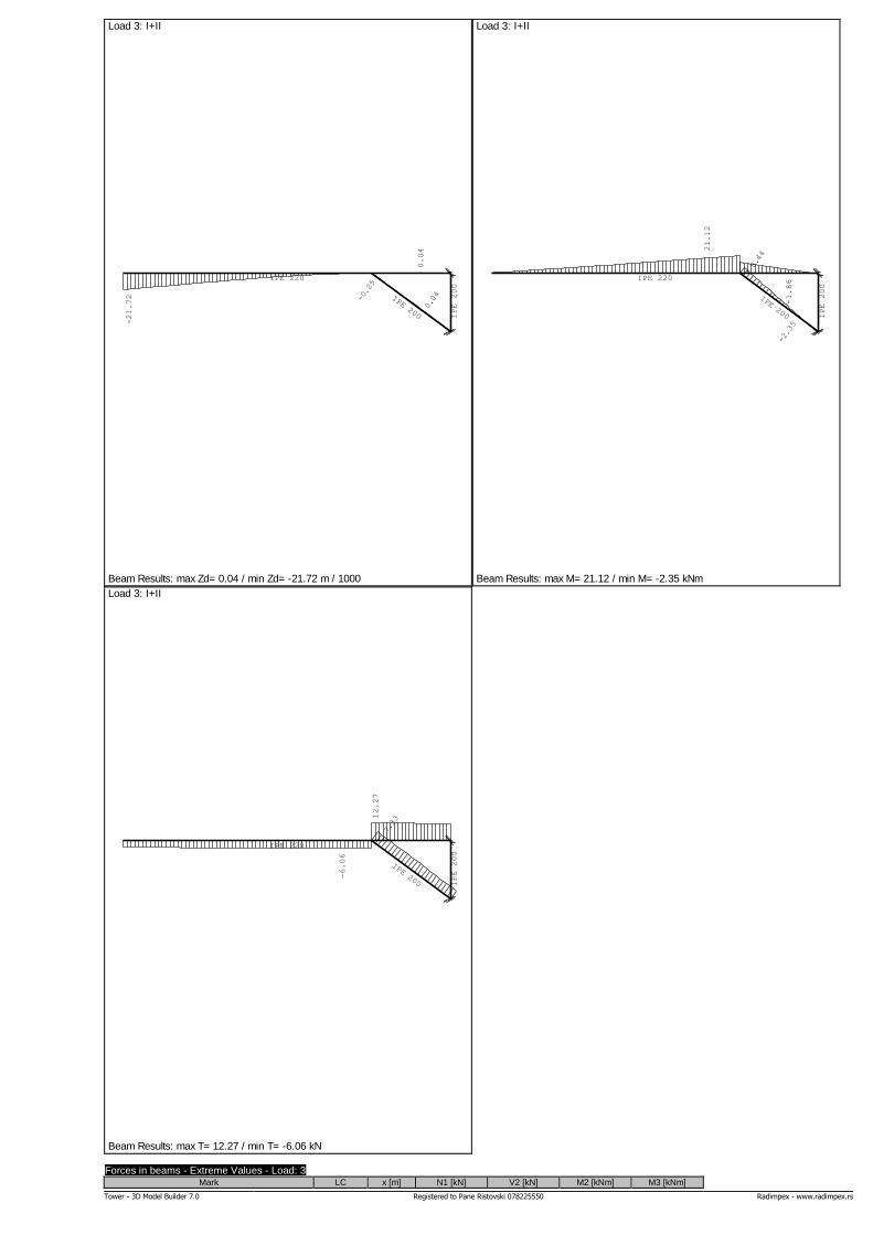
Tower - 3D Model Builder 7.0 Registered to Pane Ristovski 078225550 Radimpex - www.radimpex.rs
IPE 220
IPE 200 IPE 200
-0.25
0.04
-21.72
0.04
Load 3: I+II
Beam Results: max Zd= 0.04 / min Zd= -21.72 m / 1000
IPE 220
IPE 200 IPE 200
8.44
-2.35
21.12
-1.86
Load 3: I+II
Beam Results: max M= 21.12 / min M= -2.35 kNm
IPE 220
IPE 200 IPE 200
7.33
-6.06
12.27
Load 3: I+II
Beam Results: max T= 12.27 / min T= -6.06 kN
Forces in beams - Extreme Values - Load: 3 Mark LC x [m] N1 [kN] V2 [kN] M2 [kNm] M3 [kNm]
Tower - 3D Model Builder 7.0 Registered to Pane Ristovski 078225550 Radimpex - www.radimpex.rs
(2 - 3) 3 1.500 |-40.524| -7.063 0.000 2.352
(1 - 4) 3 5.000 |36.657| -11.957 0.000 1.861
(4 - 3) 3 0.000 |0.103| 0.000 0.000 0.000
(4 - 3) 3 0.900 |-0.099| 0.000 0.000 0.000
(1 - 4) 3 3.800 36.657 |-12.272| 0.000 -12.677
(2 - 3) 3 0.000 -40.322 |-7.332| 0.000 -8.444
(1 - 4) 3 3.800 0.000 |6.056| 0.000 -21.121
(1 - 4) 3 3.800 0.000 6.056 0.000 |-21.121|
(2 - 3) 3 0.000 -40.322 -7.332 0.000 |-8.444|
(2 - 3) 3 1.500 -40.524 -7.063 0.000 |2.352|
(1 - 4) 3 5.000 36.657 -11.957 0.000 |1.861|
Deformation of beams (LCS) - Extreme Values - Load: 3 Mark LC x [m] u2 [mm]
(1 - 4) 3 0.000 |-21.717|
(2 - 3) 3 0.000 |-0.240|
(2 - 3) 3 1.000 |0.067|
(1 - 4) 3 4.600 |0.041|
Deformation of beams (Global) - Extreme Values - Load: 3 Mark LC x [m] Zd [mm]
(1 - 4) 3 0.000 |-21.717|
(2 - 3) 3 0.000 |-0.252|
(1 - 4) 3 4.600 |0.041|
(2 - 3) 3 1.000 |0.035|
IPE 220
IPE 200 IPE 200
36.66 1.86
36.66 2.35
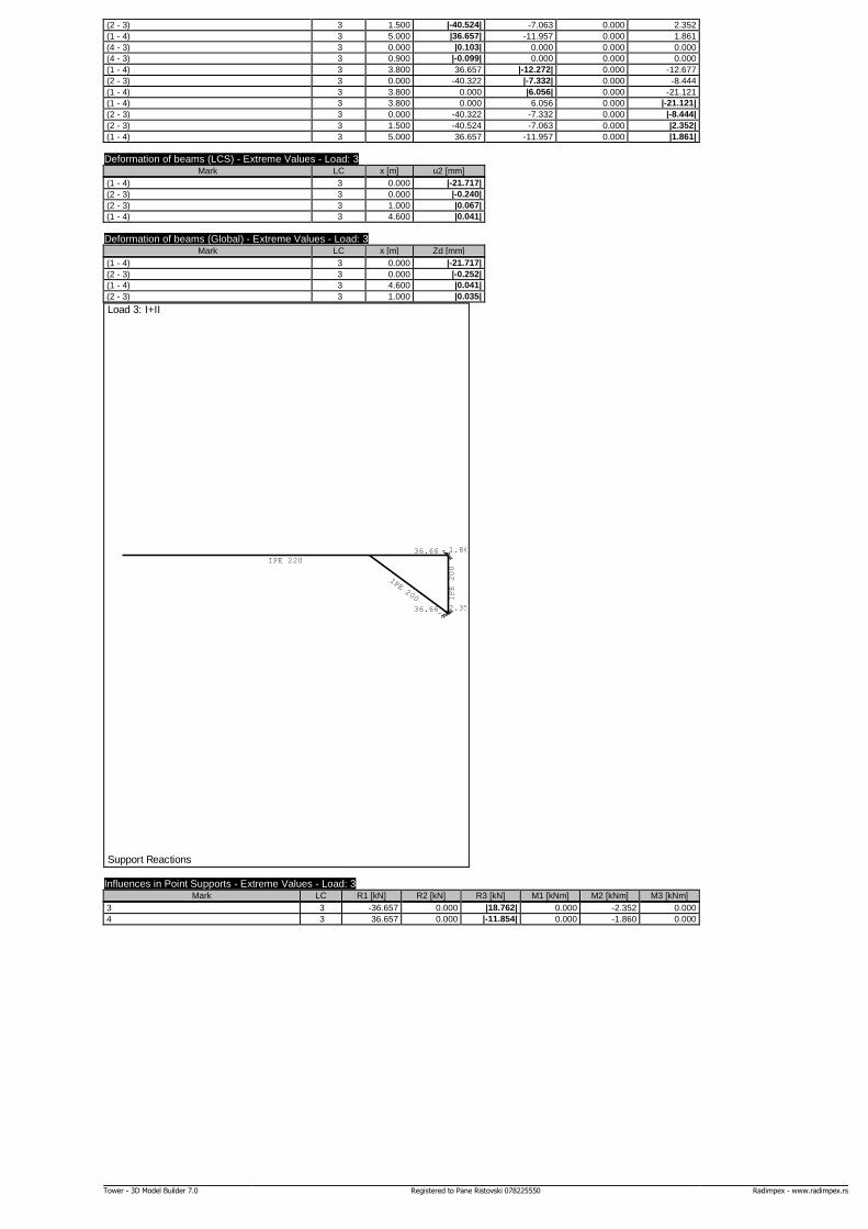
Load 3: I+II
Support Reactions
Influences in Point Supports - Extreme Values - Load: 3 Mark LC R1 [kN] R2 [kN] R3 [kN] M1 [kNm] M2 [kNm] M3 [kNm]
3 3 -36.657 0.000 |18.762| 0.000 -2.352 0.000
4 3 36.657 0.000 |-11.854| 0.000 -1.860 0.000
Tower - 3D Model Builder 7.0 Registered to Pane Ristovski 078225550 Radimpex - www.radimpex.rs
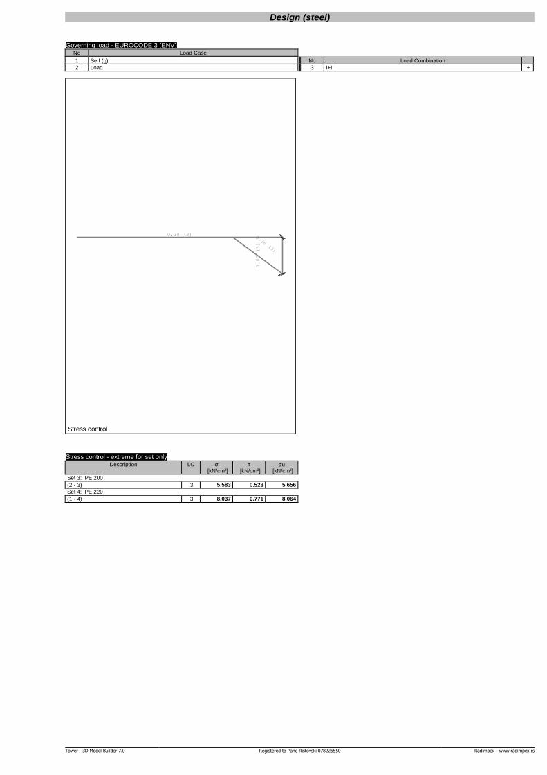
Design (steel)
Governing load - EUROCODE 3 (ENV) No Load Case
1 Self (g)
2 Load
No Load Combination
3 I+II +
0.38 (3) 0.26 (3)
0.00 (3)
Stress control
Stress control - extreme for set only Description LC σ τ σu
[kN/cm²] [kN/cm²] [kN/cm²]
Set 3: IPE 200
(2 - 3) 3 5.583 0.523 5.656
Set 4: IPE 220
(1 - 4) 3 8.037 0.771 8.064
Tower - 3D Model Builder 7.0 Registered to Pane Ristovski 078225550 Radimpex - www.radimpex.rs
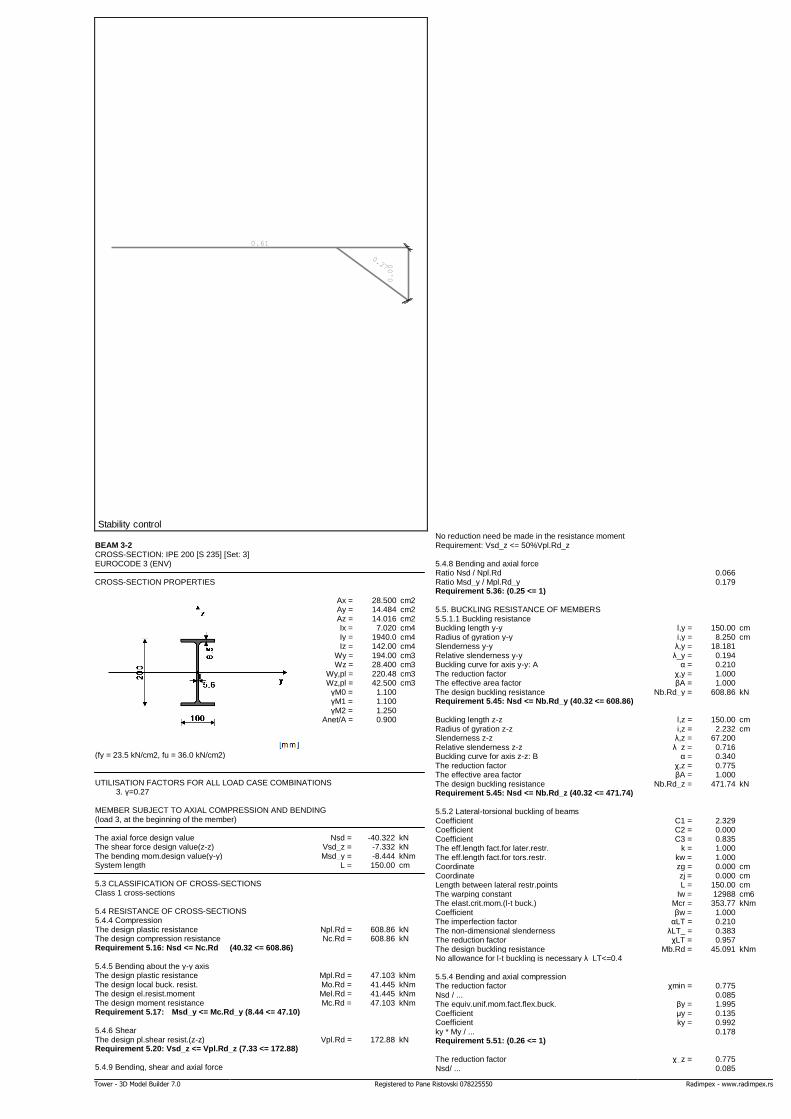
0.61
0.27
0.00
Stability control BEAM 3-2 CROSS-SECTION: IPE 200 [S 235] [Set: 3] EUROCODE 3 (ENV) CROSS-SECTION PROPERTIES
Ax = 28.500 cm2 Ay = 14.484 cm2 Az = 14.016 cm2 Ix = 7.020 cm4 Iy = 1940.0 cm4 Iz = 142.00 cm4 Wy = 194.00 cm3 Wz = 28.400 cm3 Wy,pl = 220.48 cm3 Wz,pl = 42.500 cm3 γM0 = 1.100 γM1 = 1.100 γM2 = 1.250 Anet/A = 0.900
(fy = 23.5 kN/cm2, fu = 36.0 kN/cm2) UTILISATION FACTORS FOR ALL LOAD CASE COMBINATIONS 3. γ=0.27 MEMBER SUBJECT TO AXIAL COMPRESSION AND BENDING (load 3, at the beginning of the member) The axial force design value Nsd = -40.322 kN The shear force design value(z-z) Vsd_z = -7.332 kN The bending mom.design value(y-y) Msd_y = -8.444 kNm System length L = 150.00 cm 5.3 CLASSIFICATION OF CROSS-SECTIONS Class 1 cross-sections 5.4 RESISTANCE OF CROSS-SECTIONS 5.4.4 Compression The design plastic resistance Npl.Rd = 608.86 kN The design compression resistance Nc.Rd = 608.86 kN Requirement 5.16: Nsd <= Nc.Rd (40.32 <= 608.86) 5.4.5 Bending about the y-y axis The design plastic resistance Mpl.Rd = 47.103 kNm The design local buck. resist. Mo.Rd = 41.445 kNm The design el.resist.moment Mel.Rd = 41.445 kNm The design moment resistance Mc.Rd = 47.103 kNm Requirement 5.17: Msd_y <= Mc.Rd_y (8.44 <= 47.10)
5.4.6 Shear The design pl.shear resist.(z-z) Vpl.Rd = 172.88 kN Requirement 5.20: Vsd_z <= Vpl.Rd_z (7.33 <= 172.88)
5.4.9 Bending, shear and axial force
No reduction need be made in the resistance moment Requirement: Vsd_z <= 50%Vpl.Rd_z 5.4.8 Bending and axial force Ratio Nsd / Npl.Rd 0.066 Ratio Msd_y / Mpl.Rd_y 0.179 Requirement 5.36: (0.25 <= 1)
5.5. BUCKLING RESISTANCE OF MEMBERS 5.5.1.1 Buckling resistance Buckling length y-y l,y = 150.00 cm Radius of gyration y-y i,y = 8.250 cm Slenderness y-y λ,y = 18.181 Relative slenderness y-y λ_y = 0.194 Buckling curve for axis y-y: A α = 0.210 The reduction factor χ,y = 1.000 The effective area factor βA = 1.000 The design buckling resistance Nb.Rd_y = 608.86 kN Requirement 5.45: Nsd <= Nb.Rd_y (40.32 <= 608.86)
Buckling length z-z l,z = 150.00 cm Radius of gyration z-z i,z = 2.232 cm Slenderness z-z λ,z = 67.200 Relative slenderness z-z λ_z = 0.716 Buckling curve for axis z-z: B α = 0.340 The reduction factor χ,z = 0.775 The effective area factor βA = 1.000 The design buckling resistance Nb.Rd_z = 471.74 kN Requirement 5.45: Nsd <= Nb.Rd_z (40.32 <= 471.74)
5.5.2 Lateral-torsional buckling of beams Coefficient C1 = 2.329 Coefficient C2 = 0.000 Coefficient C3 = 0.835 The eff.length fact.for later.restr. k = 1.000 The eff.length fact.for tors.restr. kw = 1.000 Coordinate zg = 0.000 cm Coordinate zj = 0.000 cm Length between lateral restr.points L = 150.00 cm The warping constant Iw = 12988 cm6 The elast.crit.mom.(l-t buck.) Mcr = 353.77 kNm Coefficient βw = 1.000 The imperfection factor αLT = 0.210 The non-dimensional slenderness λLT_ = 0.383 The reduction factor χLT = 0.957 The design buckling resistance Mb.Rd = 45.091 kNm No allowance for l-t buckling is necessary λ_LT<=0.4 5.5.4 Bending and axial compression The reduction factor χmin = 0.775 Nsd / ... 0.085 The equiv.unif.mom.fact.flex.buck. βy = 1.995 Coefficient μy = 0.135 Coefficient ky = 0.992 ky * My / ... 0.178 Requirement 5.51: (0.26 <= 1)
The reduction factor χ_z = 0.775 Nsd/ ... 0.085
Tower - 3D Model Builder 7.0 Registered to Pane Ristovski 078225550 Radimpex - www.radimpex.rs
The reduction factor χLT = 0.957 The equiv.unif.mom.fact.(l-t.buck.) βM.LT = 1.995 Coefficient μLT = 0.064 Coefficient kLT = 0.995 kLT * My / ... 0.186 Requirement 5.52: (0.27 <= 1)
5.6 SHEAR BUCKLING RESISTANCE For shear along z-z axis The relevant width d = 18.300 cm The relevant thickness tw = 0.560 cm No intermediate transverse stiffeners Buckling factor for shear kτ = 5.340 No check for resistance to shear buckling need be made Requirement: d / tw <= 69 ε (32.68 <= 69.00) 5.6.7 Interaction between shear force,bend.and axial force For shear along z-z axis The design pl.resist.mom.(flanges) Mf.Rd = 36.159 kNm Criteria 5.66a and 5.66b are satisfied
5.7 RESISTANCE OF WEBS TO TRANSVERSE FORCES 5.7.7 Flange induced buckling The factor (class 1 flanges) k = 0.300 The area of the web Aw = 11.200 cm2 The area of the compression flange Afc = 8.500 cm2 Flange induced buckling is prevented Requirement 5.80: (32.68 <= 307.73)
BEAM 4-1 CROSS-SECTION: IPE 220 [S 235] [Set: 4] EUROCODE 3 (ENV) CROSS-SECTION PROPERTIES
Ax = 33.400 cm2 Ay = 17.489 cm2 Az = 15.911 cm2 Ix = 9.100 cm4 Iy = 2770.0 cm4 Iz = 205.00 cm4 Wy = 251.82 cm3 Wz = 37.273 cm3 Wy,pl = 287.26 cm3 Wz,pl = 55.660 cm3 γM0 = 1.100 γM1 = 1.100 γM2 = 1.250 Anet/A = 0.900
(fy = 23.5 kN/cm2, fu = 36.0 kN/cm2) UTILISATION FACTORS FOR ALL LOAD CASE COMBINATIONS 3. γ=0.61 MEMBER SUBJECT TO BENDING (load 3, at 380.0 cm from the start of the member) The shear force design value(z-z) Vsd_z = 6.056 kN The bending mom.design value(y-y) Msd_y = -21.121 kNm System length L = 500.00 cm 5.3 CLASSIFICATION OF CROSS-SECTIONS Class 1 cross-sections 5.4 RESISTANCE OF CROSS-SECTIONS 5.4.5 Bending about the y-y axis The design plastic resistance Mpl.Rd = 61.368 kNm The design local buck. resist. Mo.Rd = 53.798 kNm The design el.resist.moment Mel.Rd = 53.798 kNm The design moment resistance Mc.Rd = 61.368 kNm Requirement 5.17: Msd_y <= Mc.Rd_y (21.12 <= 61.37)
5.4.6 Shear The design pl.shear resist.(z-z) Vpl.Rd = 196.25 kN Requirement 5.20: Vsd_z <= Vpl.Rd_z (6.06 <= 196.25)
5.4.7 Bending and shear No reduction need be made in the resistance moment Requirement: Vsd_z <= 50%Vpl.Rd_z 5.5. BUCKLING RESISTANCE OF MEMBERS 5.5.2 Lateral-torsional buckling of beams Coefficient C1 = 1.285 Coefficient C2 = 1.562 Coefficient C3 = 0.753 The eff.length fact.for later.restr. k = 1.000 The eff.length fact.for tors.restr. kw = 1.000 Coordinate zg = 0.000 cm Coordinate zj = 0.000 cm Length between lateral restr.points L = 500.00 cm The warping constant Iw = 22672 cm6 The elast.crit.mom.(l-t buck.) Mcr = 50.893 kNm Coefficient βw = 1.000 The imperfection factor αLT = 0.210 The non-dimensional slenderness λLT_ = 1.152 The reduction factor χLT = 0.561 The design buckling resistance Mb.Rd = 34.440 kNm Requirement 5.48: Msd_y <= Mb.Rd (21.12 <= 34.44) 5.6 SHEAR BUCKLING RESISTANCE For shear along z-z axis The relevant width d = 20.160 cm The relevant thickness tw = 0.590 cm No intermediate transverse stiffeners Buckling factor for shear kτ = 5.340 No check for resistance to shear buckling need be made Requirement: d / tw <= 69 ε (34.17 <= 69.00)
5.6.7 Interaction between shear force,bend.and axial force For shear along z-z axis The design pl.resist.mom.(flanges) Mf.Rd = 47.564 kNm Criteria 5.66a and 5.66b are satisfied 5.7 RESISTANCE OF WEBS TO TRANSVERSE FORCES 5.7.7 Flange induced buckling The factor (class 1 flanges) k = 0.300 The area of the web Aw = 12.980 cm2 The area of the compression flange Afc = 10.120 cm2 Flange induced buckling is prevented Requirement 5.80: (34.17 <= 303.61) Check of the shear resistance (load 3, at 380.0 cm from the start of the member) The axial force design value Nsd = 36.657 kN The shear force design value(z-z) Vsd_z = -12.272 kN The bending mom.design value(y-y) Msd_y = -12.677 kNm System length L = 500.00 cm 5.4 RESISTANCE OF CROSS-SECTIONS 5.4.6 Shear The design pl.shear resist.(z-z) Vpl.Rd = 196.25 kN Requirement 5.20: Vsd_z <= Vpl.Rd_z (12.27 <= 196.25) 5.6 SHEAR BUCKLING RESISTANCE For shear along z-z axis The relevant width d = 20.160 cm The relevant thickness tw = 0.590 cm No intermediate transverse stiffeners Buckling factor for shear kτ = 5.340 No check for resistance to shear buckling need be made Requirement: d / tw <= 69 ε (34.17 <= 69.00)