LIFEPAK 15 MONITOR/DEFIBRILLATORLIFEPAK 15 Monitor/Defibrillator Service Manual Introduction...
527
SERVICE MANUAL LIFEPAK ® 15 MONITOR/DEFIBRILLATOR © 2011-2015 Physio-Control, Inc. 3309059-003
Transcript of LIFEPAK 15 MONITOR/DEFIBRILLATORLIFEPAK 15 Monitor/Defibrillator Service Manual Introduction...

SERVICE MANUAL
LIFEPAK® 15 MONITOR/DEFIBRILLATOR
© 2011-2015 Physio-Control, Inc.
3309059-003

LIFEPAK 15 Monitor/Defibrillator Section Menu
iiBack Index
Section Navigator
1 Introduction
page 11
2 Safety
page 29
3 Device Description
page 48
4 Modes of Operation
page 89
5 Troubleshooting
page 98
6 Preventive Maintenance
page 145
7 Battery Maintenance
page 158
8 Replacement Procedures
page 169
page 89
9 Assembly Diagrams and Parts Lists
page 366
page 366

LIFEPAService
Secti Index iii
1
Table ofSection Navig ............................................................. iiIntroduction ........................................................... 11
Tradem ........................................................... 12Using ........................................................... 13Naviga ........................................................... 14Servic ........................................................... 15Contac ........................................................... 16Respo ........................................................... 17Device ........................................................... 18Servic ........................................................... 19Recyc .......................................................... 20Warran ........................................................... 21Config ........................................................... 22Glossa ........................................................... 23Acrony ........................................................... 25
Safety ......... ........................................................... 29Terms ........................................................... 30Genera ........................................................... 31Symbo ........................................................... 36
Device Descr ........................................................... 48Introd ........................................................... 49Physic ........................................................... 54Device ........................................................... 65System .......................................................... 70Functi .......................................................... 74
K 15 Monitor/Defibrillator Manual
on Menu Section Contents Back
Contentsator ............................................................................................................................................................................................................................arks .........................................................................................................
Adobe Reader .............................................................................................ting Through the Manual .............................................................................e Personnel Qualifications ............................................................................ting Physio-Control ....................................................................................
nsibility for Information ............................................................................... Tracking ...................................................................................................e Information ..............................................................................................ling Information ...........................................................................................ty .............................................................................................................uration Information .....................................................................................ry ..............................................................................................................ms .............................................................................................................................................................................................................................. .................................................................................................................l Warnings .................................................................................................ls ..............................................................................................................iption .........................................................................................................uction ........................................................................................................al Description and Features .........................................................................s, Options, Supplies, and Accessories .......................................................... Context Diagrams ......................................................................................
onal Descriptions .........................................................................................

LIFEPAService
Secti Index iv
1Modes of Ope ........................................................... 89
Manua ........................................................... 90AED M ........................................................... 91Setup ........................................................... 92Servic .......................................................... 94Demo ........................................................... 96Archiv ........................................................... 97
Troubleshoot ........................................................... 98Troubl ........................................................... 99Using ......................................................... 106Device ......................................................... 108Device ......................................................... 110Servic ......................................................... 113Proces ........................................................ 115Counte ......................................................... 116Clear M ......................................................... 118Servic ........................................................ 119Utility ......................................................... 121User I ......................................................... 122Data M ........................................................ 124System ........................................................ 125Proces ........................................................ 126ECG S ......................................................... 128Patien ......................................................... 129Therap ........................................................ 130Printe ......................................................... 137Power ......................................................... 138Serial ......................................................... 139
K 15 Monitor/Defibrillator Manual
on Menu Section Contents Back
ration ........................................................................................................l Mode ......................................................................................................ode ..........................................................................................................Mode .........................................................................................................e Mode........................................................................................................Mode .........................................................................................................e Mode ......................................................................................................ing .............................................................................................................eshooting Chart ..........................................................................................the Service/Status Features ......................................................................... Log ..................................................................................................... Data .........................................................................................................e Log .........................................................................................................sing Service Log Codes ................................................................................rs .............................................................................................................emory ......................................................................................................
e Log Code Categories .................................................................................. Service Codes ............................................................................................nterface Service Codes ................................................................................anagement Service Codes............................................................................ Monitor Service Codes ...............................................................................sor Control Service Codes .............................................................................ervice Codes ...............................................................................................t Parameter Service Codes ...........................................................................y Service Codes...........................................................................................
r Service Codes ........................................................................................... Management Service Codes .........................................................................Communication Service Codes .....................................................................

LIFEPAService
Secti Index v
1Correc ......................................................... 140Servic ......................................................... 143Displa ......................................................... 144
Preventive M ......................................................... 145Device ......................................................... 146Device ......................................................... 147Preven ......................................................... 148Sched ......................................................... 149Settin ......................................................... 150Device ......................................................... 151Suppo ......................................................... 152Cleani ......................................................... 153Enviro ......................................................... 155A12 P ......................................................... 156
Battery Maint ........................................................ 158Batter ........................................................ 159Batter ......................................................... 160Batter ......................................................... 163Chargi ......................................................... 164Discar ......................................................... 165Storin ........................................................ 166Receiv ......................................................... 167Coin C ......................................................... 168
Replacement ......................................................... 169Summ ......................................................... 170Warnin ......................................................... 173Static- ......................................................... 174Tools L ......................................................... 176
K 15 Monitor/Defibrillator Manual
on Menu Section Contents Back
tive Action Codes ........................................................................................e LED ........................................................................................................y Pixels Test ...............................................................................................aintenance ................................................................................................. Self Tests ................................................................................................. User Test ..................................................................................................tive Maintenance and Testing Schedule ........................................................uled Replacement Items ..............................................................................g/Resetting the Maintenance Prompt Interval ................................................. Useful Life ................................................................................................rt Policy .....................................................................................................ng .............................................................................................................nmental Conditions .....................................................................................rinter Maintenance ......................................................................................enance .......................................................................................................y General Characteristics ..............................................................................y Status Indicators ......................................................................................y Performance Characteristics ......................................................................ng the Batteries Using the Station or Mobile Li-ion Battery Charger .................ding/Recycling Batteries ..............................................................................g Batteries...................................................................................................ing New Batteries .......................................................................................ell Battery .................................................................................................. Procedures ................................................................................................ary of Replacement Procedures ....................................................................gs and Cautions .........................................................................................Sensitive Device Handling ...........................................................................ist ............................................................................................................

LIFEPAService
Secti Index vi
1Capac ......................................................... 177Capac ........................................................ 178Discha ......................................................... 179Saving ......................................................... 180Disass ........................................................ 181Reasse ......................................................... 184Inside ......................................................... 189Interfa ......................................................... 190Backli ......................................................... 195Printe ......................................................... 198Main K ......................................................... 200Displa ......................................................... 202LCD D ........................................................ 204Displa ......................................................... 206Front C ......................................................... 208System ......................................................... 212Backli ......................................................... 213Therap ......................................................... 214Printe ........................................................ 216Main K ........................................................ 217Speed ......................................................... 218Install ........................................................ 220Printe ......................................................... 221Speak ........................................................ 223LCD D ......................................................... 226Printe ......................................................... 227Inside ......................................................... 228System ......................................................... 232
K 15 Monitor/Defibrillator Manual
on Menu Section Contents Back
itor Discharge Tool ......................................................................................itor Discharging Procedure ............................................................................rging the C15 Pacing Capacitor ................................................................... and Restoring the Setup Configuration ........................................................embling the Case.........................................................................................mbling the Case .........................................................................................
Front Case Diagram ....................................................................................ce PCB (A05) Replacement .........................................................................ght PCB (A08) Replacement ........................................................................r Control Keypad (A09) Replacement ............................................................eypad (A10) Replacement ..........................................................................
y Shield Replacement .................................................................................isplay Assembly (A11) Replacement ..............................................................y Lens Replacement ....................................................................................ase Replacement ......................................................................................./Interface PCB Cable (W04) Replacement ....................................................
ght/Interface PCB Cable (W06) Replacement .................................................y Connector Cable (W11) Replacement ........................................................
r Control Keypad/Interface PCB Cable (W12) Replacement...............................eypad/Interface PCB Cable (W13) Replacement.............................................
Dial Assembly (W15) Replacement ..............................................................ing the Speed Dial Assembly (W15) ...............................................................r Assembly/Interface PCB Cable (W16) Replacement ......................................er Assembly (W17) Replacement ...................................................................isplay Assembly/Interface PCB Cable (W18) Replacement ..............................r Assembly/Chassis Ground Cable (W19) Replacement .................................... Rear Case Diagrams ................................................................................... (A01)/Therapy (A04) PCB Assembly Replacement .......................................

LIFEPAService
Secti Index vii
1Install ......................................................... 239Power ......................................................... 253OEM P ......................................................... 261Transf ......................................................... 268Energy ......................................................... 271SpO2 ......................................................... 274Interco ........................................................ 284NIBP ......................................................... 287Biphas ......................................................... 298EMI S ......................................................... 305NIBP ......................................................... 306Param ......................................................... 309Rear C ......................................................... 315Handl ......................................................... 321Paddle ......................................................... 322Power ......................................................... 323Power ......................................................... 324Power ......................................................... 326ECG C ......................................................... 328System ......................................................... 331Batter ......................................................... 334USB F ......................................................... 338Biphas ......................................................... 340OEM P ......................................................... 342SpO2 ......................................................... 344OEM P ......................................................... 346OEM P ......................................................... 348CO2 In ......................................................... 350
K 15 Monitor/Defibrillator Manual
on Menu Section Contents Back
ing the System (A01)/Therapy (A04) PCB Assembly ....................................... PCB (A03) Replacement .............................................................................CB (A06) Replacement ...............................................................................er Relay Assembly (A13) Replacement .......................................................... Storage Capacitor (A15) Replacement .........................................................PCB (A16) Replacement ..............................................................................nnect Bracket (A17) Replacement................................................................
(A21)/CO2 (A23) Module Replacement .........................................................ic Module (A22)/Inductive Resistor (A14) Replacement .................................
hield Replacement ......................................................................................Connector Replacement ...............................................................................eter Bezel Replacement ...............................................................................ase Replacement ........................................................................................e Replacement ............................................................................................ Retainer Cover Replacement ......................................................................
/System PCB Cable (W01) Replacement ......................................................../Therapy PCB Cable (W02) Replacement ......................................................./Contact PCB Cable (W05) Replacement .......................................................onnector Cable (W07) Replacement ............................................................. Connector Cable (W08) and Auxiliary Connector Cable (W09) Replacement ...
y Pins / Power PCB Cable (W10) Replacement ...............................................lex Module (W14) Replacement ...................................................................ic Cable (W20) Replacement .......................................................................CB/SpO2 (W21) Module Cable Replacement .................................................Connector Cable (W22) Replacement ............................................................CB/CO2 Module Cable (W26) Replacement ..................................................CB/NIBP Module Cable (W27) Replacement .................................................let Connector Cable (W28) Replacement ......................................................

LIFEPAService
Secti Index viii
1CO2 A ......................................................... 353Invasiv ......................................................... 355Tempe ......................................................... 357Contac ......................................................... 359Printe ......................................................... 360Coin B ......................................................... 362Batter ......................................................... 364 Softw ......................................................... 365
Assembly Dia ......................................................... 366Sectio ......................................................... 367Main D ......................................................... 368Extern ......................................................... 371Front P ........................................................ 377System ......................................................... 386Param ......................................................... 391Rear D ......................................................... 399OEM O ......................................................... 412Label ......................................................... 417Conne ......................................................... 443Repair ......................................................... 491Defibr ......................................................... 521Orderi ......................................................... 522
Index .......... ......................................................... 523
K 15 Monitor/Defibrillator Manual
on Menu Section Contents Back
dapter Cable (W30) Replacement .................................................................e Pressure Connector Assembly (W33) Replacement ......................................rature Cable Assembly (W35) Replacement ...................................................t PCB (A07) Replacement ...........................................................................
r Assembly (A12) Replacement .....................................................................attery Replacement ....................................................................................y Pin Replacement ......................................................................................are and Device Upgrades .............................................................................grams and Parts Lists ..................................................................................n Glossary ..................................................................................................iagrams ....................................................................................................
al Parts Diagrams and Lists .........................................................................arts Diagrams and Parts List ......................................................................../Therapy PCB Assembly Diagrams and Parts Lists .........................................
eter Bezel Diagrams and Parts Lists ..............................................................iagrams and Parts List ................................................................................ptional Assemblies, Diagrams and Parts Lists ...............................................
Language Parts ...........................................................................................ction Diagrams for Assemblies, Control Boards, Cables, and Connectors ........... Kits ..........................................................................................................illator Part Number and Serial Number ..........................................................ng Parts .......................................................................................................................................................................................................................

Index
LIFEPAServic
IntroductionContents
11
1IntroduThis service 5 monitor/defibrillator. A separate publication, the LIFEPAK 15 , and emergency care providers. The operating instructions ce.
NOT enu item, or screen message appears in all
This section
• Tr• U• N• S• C• R• D• S• R• W• C• G• A
Section Menu Back
K 15 Monitor/Defibrillatore Manualction manual describes how to maintain, test, troubleshoot, and repair the LIFEPAK 1 Monitor/Defibrillator Operating Instructions, is for use by physicians, clinicians
provide step-by-step instructions as well as operator-level testing and maintenan
E: Hyperlinks appear in “blue text.” Text that indicates the name of a button, mcaps (for example, press ANALYZE, select MANUAL MODE.
covers the following topics:
ademarks (p. 12)sing Adobe Reader (p. 13)avigating Through the Manual (p. 14)ervice Personnel Qualifications (p. 15)ontacting Physio-Control (p. 16)esponsibility for Information (p. 17)evice Tracking (p. 18)ervice Information (p. 19)ecycling Information (p. 20)arranty (p. 21)onfiguration Information (p. 22)lossary (p. 23)cronyms (p. 25)

LIFEPAService
IntroductionTrademarks
Secti Index 12
1TrademarkLIFEPAK, LIF O, and DERMA-JEL are registered trademarks of Physio-Contro System, SunVue, and DT EXPRESS are trademarks of Physio-Con tion in the US and/or other countries. Adobe is a trademark of registered trademarks of Masimo Corporation. Red, LNCS, SpCO, registered trademarks of Oridion Medical, Ltd. The Oridion medi atents: 6,428,483; 6,997,880; 5,300,859; 6,437,316 a IO-TEK are registered trademarks and QED-6H is a trademark of SIG, Inc. CASMED is a registered trademark of CAS Medical Syste tem Technology is a trademark of Ludlow Technical Products. Sp
© 2011-201
330905
K 15 Monitor/Defibrillator Manual
on Menu Section Contents Back
sEPAK CR, LIFEPAK EXPRESS, LIFENET, FASTPAK, LIFE•PATCH, QUIK-COMBl, Inc. CODE SUMMARY, CODE-STAT, PARTSLINE, REDI-PAK, Shock Advisory trol, Inc. Microsoft and Windows are registered trademarks of Microsoft CorporaAdobe Systems Incorporated. Masimo, the Radical logo, Rainbow, and SET are and SpMet are trademarks of Masimo Corporation. CapnoLine and FilterLine arecal capnography in this product is covered by one or more of the following US pnd their foreign equivalents. Additional patent applications pending. Fluke and BFluke Biomedical Corporation. Bluetooth is a registered trademark of Bluetooth ms, Inc. SIGNAGEL is a registered trademark of Parker Laboratories. EDGE Sys
ecifications are subject to change without notice.
5 Physio-Control, Inc.
9-003

LIFEPAService
IntroductionUsing Adobe Reader
Secti Index 13
1Using Adob
AccesThis se n CD. For additional assistance using the Adobe
UsingBookm y navigate to main sections of the manual, simila
To view eft side of the screen.
To jum
NOTE er that bookmark level. Click the plus sign to
UsingClick t ch page in the document. Scroll through the pages
K 15 Monitor/Defibrillator Manual
on Menu Section Contents Back
e Reader
sing Adobe Reader Helprvice manual opens in Adobe Reader, which is included on this documentatio
Reader program, access ADOBE READER HELP in the HELP menu.
Bookmarksarks appear in a column on the left side of the screen. They enable you to easil
r to a table of contents.
or hide the bookmarks column, click the BOOKMARKS tab located along the l
p to a bookmark topic, click the desired topic.
: A plus sign to the left of a bookmark topic indicates additional topics exist undexpand or collapse the bookmarks.
Page Viewhe PAGES tab located to the far left of the screen to view miniature images of eaand click an image to jump quickly to that page.

LIFEPAService
IntroductionNavigating Through the Manual
Secti Index 14
1NavigatingBlue text ind in the navigation bar (at the bottom of each page) to return to y ned over a link. A navigation bar at the bottom of each page als
The navigatio
•• re currently viewing.
• the reverse order visited.
• I
K 15 Monitor/Defibrillator Manual
on Menu Section Contents Back
Through the Manualicates a hyperlink. Click a link to jump to that topic or page. Click our previous location. The pointer changes to a pointing finger when positioo provides helpful links.
n bar includes:
Click to jump to the main table of contents for the manual.
Click to jump to the table of contents for the section you a
Click to retrace your steps in a document, returning to each page in
Click to jump to the manual’s index.
Back
Section MenuSection Contents
Backndex

LIFEPAService
IntroductionService Personnel Qualifications
Secti Index 15
1Service Pe
Servic ion of the LIFEPAK 15 monitor/defibrillator. They m
• Ass• Ce• Eq
K 15 Monitor/Defibrillator Manual
on Menu Section Contents Back
rsonnel Qualificationse technicians must be properly qualified and thoroughly familiar with the operatust meet at least one of the following requirements (or the equivalent):
ociate of Applied Science, with an emphasis in biomedical electronicsrtificate of Technical Training, with an emphasis in biomedical electronicsuivalent biomedical electronics experience

LIFEPAService
IntroductionContacting Physio-Control
Secti Index 16
1Contacting
Physi11811RedmoTelephToll FrFax: 1Intern
PhysiGaljoe6222 The N
PhysiSuite 415 OriLane CNSW 2Austra
K 15 Monitor/Defibrillator Manual
on Menu Section Contents Back
Physio-Control o-Control, Inc. Willows Road NEnd, WA 98052-2003 USAone: 425.867.4000ee (USA only): 800.442.1142.425.867.4861et: www.physio-control.com
o-Control Operations Netherlands B.V.nweg 68NV Maastrichtetherlands
o-Control Australia Pty Ltd.01
on Roadove066lia

LIFEPAService
IntroductionResponsibility for Information
Secti Index 17
1ResponsibiThis service m K 15 monitor/defibrillator. This manual does not address the o ications on page 15) must consult this manual and the LIFEPAK ing of the use and maintenance of the device.
It is the respo rganization has access to the information in this service manu
K 15 Monitor/Defibrillator Manual
on Menu Section Contents Back
lity for Informationanual describes the methods required to maintain, test, and repair the LIFEPA
peration of the device. Qualified service personnel (see Service Personnel Qualif15 Monitor/Defibrillator Operating Instructions to obtain a complete understand
nsibility of our customers to ensure that the appropriate person(s) within their oal, including any warnings and cautions used throughout the manual.

LIFEPAService
IntroductionDevice Tracking
Secti Index 18
1Device Tra
Devi
The U.S. Foo to track the location of their defibrillators. If the device is loca ated, lost, stolen, exported, destroyed, permanently retired from u of the following: register the device at http://www.physio- one of the postage-paid address change cards located in the this vital tracking information.
!USA
K 15 Monitor/Defibrillator Manual
on Menu Section Contents Back
ckingce Tracking:
d and Drug Administration requires defibrillator manufacturers and distributors ted somewhere other than the shipping address or the device has been sold, donse, or if the device was not obtained directly from Physio-Control, please do one
control.com, call the device registration phone line at 1.800.426.4448, or use back of the LIFEPAK 15 Monitor/Defibrillator Operating Instructions, to update

LIFEPAService
IntroductionService Information
Secti Index 19
1Service Inf
Before should be familiar with the information provid
A qual d inspect any device that has been dropped, damag s listed in the Performance Inspection Proced
Replac al assembly level. Replacements and adjust ssembly level simplify repair and servicing proced
To obt ervice or sales representative. In the USA, call Ph your local Physio-Control representative. When
• Mo• Se• Ob
K 15 Monitor/Defibrillator Manual
on Menu Section Contents Back
ormation attempting to clean or repair any assembly in the device, the service technicianed in Preventive Maintenance (p. 145).
ified service technician (see Service Personnel Qualifications on page 15) shouled, or abused to verify that the device is operating within performance standardures (PIP), and that the leakage current values are acceptable.
ement procedures for the device are limited to those items accessible at the finments must be made by qualified service personnel. Replacements at the final aures and help ensure correct device operation and calibration.
ain service and maintenance for your device, contact your local Physio-Control sysio-Control Technical Support at 1.800.442.1142. Outside the USA, contact you call Physio-Control to request service, provide the following information:
del number and part numberrial numberservation of the problem that led to the call

LIFEPAService
IntroductionRecycling Information
Secti Index 20
1Recycling Recycle the d
• Re al regulations. For instructions on disposing of
• Pre cled.• Re local clinical procedures for recycling.• Re local guidelines and instructions provided in
thi g/Recycling Batteries (p. 165)• Pa ns.
K 15 Monitor/Defibrillator Manual
on Menu Section Contents Back
Informationevice at the end of its useful life.
cycling assistance – The device should be recycled according to national and locthis product or its accessories, see www.physio-control.com/recycling.paration – The device should be clean and contaminant-free prior to being recycycling of disposable electrodes – After using disposable electrodes, follow yourcycling of batteries – The device uses rechargeable Lithium-ion batteries. Follow s service manual for discarding and recycling batteries as described in Discardinckaging – packaging should be recycled according to national and local regulatio

LIFEPAService
IntroductionWarranty
Secti Index 21
1WarrantyTo obtain a d o to www.physio-control.com.
Using defibri er than Physio-Control is not recommended. Physio-Contro defibrillators if they are used in conjunction with defibrillation ibutable to defibrillation electrodes or other parts or supplies not
K 15 Monitor/Defibrillator Manual
on Menu Section Contents Back
etailed warranty statement, contact your local Physio-Control representative or g
llation electrodes, adapter devices, or other parts and supplies from sources othl has no information regarding the performance or effectiveness of its LIFEPAK electrodes or other parts and supplies from other sources. If device failure is attrmanufactured by Physio-Control, this may void the warranty.

LIFEPAService
IntroductionConfiguration Information
Secti Index 22
1ConfiguratThis service m
• LIF ion• LIF• EC• Ma• AE• No• Blu• 12• Ori• Ma• CA• 2 C• Vit• Tem option cannot be installed on the same
dev
K 15 Monitor/Defibrillator Manual
on Menu Section Contents Back
ion Informationanual is relevant for the following devices and options:
EPAK 15 monitor/defibrillator Version 1 (V1) device without auxiliary power optEPAK 15 monitor/defibrillator Version 2 (V2) device with auxiliary power optionG monitoring — standardnual mode defibrillation — standardD mode — standardninvasive pacing — standardetooth® wireless technology option (within approved countries)-lead ECG optiondion® CO2 optionsimo® SpO2/SpCO™/SpMet™ optionsSMED® NIBP monitoring optionhannel Invasive pressure option
al signs and ST trending optionperature monitoring option (V2 only; temperature option and invasive pressure ice)

LIFEPAService
IntroductionGlossary
Secti Index 23
1Glossary
The fo
• Bip rse current phase of shorter duration and dec onential (BTE).
• Au ted treatment protocol for patients in cardiac arr
• Sh mode for detecting a shockable rhythm. For mo
• Co nt ECG in LEADS or PADDLES for a pot N (Setup/Alarms) or after pressing the AL g instructions.
• CO sociated with key events, such as analysis or sho UMMARY report.
• CO CO2, and respiration rate (referred to hen
• En of expiration.
• Eve nt record; part of the CODE SUMMARY rep
• No stolic, diastolic, and mean arterial blood pre
• No o the heart through large adhesive electrodes pla
K 15 Monitor/Defibrillator Manual
on Menu Section Contents Back
llowing are definitions of terms used throughout this service manual.
hasic waveform — Characterized by a positive current phase followed by a revereased magnitude. The waveform pulse characteristic is biphasic truncated exp
tomated external defibrillator (AED) — An Automated ECG analysis and a prompest.
ock Advisory System (SAS) — A computerized ECG analysis system used in AEDre information about SAS, see Appendix C in the operating instructions.
ntinuous patient surveillance system (CPSS) — A feature that monitors the patieentially shockable rhythm. CPSS is active when the VF/VT ALARM is selected OARMS button. For more information about CPSS, see Appendix C in the operatin
DE SUMMARY™ report — A summary report that includes the ECG segments asck. See “Data Management” in the operating instructions for a sample CODE S
2 monitor — An optional noninvasive capnometer that monitors CO2, EtCO2, Ficeforth as CO2).
d-tidal carbon dioxide (EtCO2) — EtCO2 is the measurement of CO2 at the end
nt log summary — A report summarizing important events for a particular patieort.
ninvasive blood pressure (NIBP) — An optional oscillometric measurement of syssure, along with pulse rate.
ninvasive pacing — A standard feature that delivers repetitive electrical stimuli tced on the patient’s chest.

LIFEPAService
IntroductionGlossary
Secti Index 24
1• QU lows monitoring of ECG, delivery of pacing
and
• QU cardiac rhythm simulator. The simulator is des defibrillator.
• Pu uration of oxygen in arterial blood, car
• Sp yhemoglobin concentration (SpCO), and me
• Tes nects to the QUIK-COMBO therapy cable. It pro
• Vit phically display and document a patient's vita
K 15 Monitor/Defibrillator Manual
on Menu Section Contents Back
IK-COMBO® pacing/defibrillation/ECG electrodes — An electrode system that al defibrillation therapy to the patient.
IK-COMBO patient simulator — A combination QC therapy cable and ECG lead igned for use in training clinical personnel to operate the LIFEPAK 15 monitor/
lse Co-oximeter — An optional noninvasive pulse oximeter that measures the satboxyhemoglobin and methemoglobin concentrations, respectively.
O2/SpCO/SpMet — The measure of functional oxygen saturation (SpO2), carboxthemoglobin concentration (SpMet) in the blood.
t Load — An accessory shipped with the LIFEPAK monitor/defibrillator that convides a 50 ohm load for shock discharge through the therapy cable.
al sign (VS) and ST segment Trends — An optional trending feature that can gral signs and ST segment measurements for up to eight hours.

LIFEPAService
IntroductionAcronyms
Secti Index 25
1AcronymsTable 1.1 list
Table
Term
AAMI
ADC
AED
Ah
AHA
AMI
ANSI
ASIC
BF
BPM
BTE
CF
CO2
K 15 Monitor/Defibrillator Manual
on Menu Section Contents Back
s acronyms and abbreviations used in this manual.
1.1— Acronyms and Abbreviations
Description
Association for the Advancement of Medical Instrumentation
Analog-to-digital conversion
Automated external defibrillator
Ampere hour
American Heart Association
Acute myocardial infarction
American National Standards Institute
Application-specific integrated circuit
Electrically isolated, external body connection
Beats per minute
Biphasic truncated exponential
Electrically isolated, direct cardiac connection
Carbon dioxide
LIFEPAService
IntroductionAcronyms
Secti Index 26
1
CPR
CPU
CPSS
DDE
DMM
DSP
DUAR
ECG
EMS
ESCC
ESD
ESU
EtCO2
FiCO2
HR
IEC
IP
LCD
Table
K 15 Monitor/Defibrillator Manual
on Menu Section Contents Back
Cardiopulmonary resuscitation
Central processing unit
Continuous patient surveillance system
Disposable defibrillation electrodes
Digital multimeter
Digital signal processor
T Dual universal asynchronous receiver/transmitter
Electrocardiogram
Emergency medical service
Energy storage capacitor charger
Electrostatic discharge
Electrosurgical unit
End-tidal carbon dioxide
Inspired carbon dioxide
Heart rate
International Electrical Commission
Invasive pressure
Liquid crystal display
1.1— Acronyms and Abbreviations (Continued)

LIFEPAService
IntroductionAcronyms
Secti Index 27
1
LED
Li-ion
mmHg
NIBP
NSR
OEM
RR
PC
PCB
PIP
PPM
PR
QRS
RTC/N
RTS
SAS
SBC
SpCO
Table
K 15 Monitor/Defibrillator Manual
on Menu Section Contents Back
Light-emitting diode
Lithium-ion
Millimeters of mercury
Noninvasive blood pressure
Normal sinus rhythm
Original equipment manufacturer
Respiration rate
Personal computer
Printed circuit board
Performance inspection procedure
Pulses per minute
Pulse rate
Refers to portions of the ECG waveform
VRAM Real-time clock/non-volatile random-access memory
Radio transparent system
Shock Advisory System
Single-Board Computer
Measurement of carboxyhemoglobin concentration
1.1— Acronyms and Abbreviations (Continued)

LIFEPAService
IntroductionAcronyms
Secti Index 28
1
.
SpO2
SpMe
SSD
TCP
USB
VF
VS
VT
μA
Table
K 15 Monitor/Defibrillator Manual
on Menu Section Contents Back
Measurement of oxygen saturation
t Measurement of methemoglobin concentration
Static-sensitive device
Test and calibration procedure
Universal serial bus
Ventricular fibrillation
Vital signs
Ventricular tachycardia
MicroAmpere
1.1— Acronyms and Abbreviations (Continued)

Index
LIFEPAServic
SafetyContents
29
2SafetyThis section e manual or on the LIFEPAK 15 monitor/defibrillator front and re d precautions in the care, use, and handling of this medical dev
• Te• G• S
Section Menu Back
K 15 Monitor/Defibrillatore Manual
describes the general safety conventions, terms, and symbols used in this servicar panels. This information is intended to alert service personnel to recommendeice.
rms (p. 30)eneral Warnings (p. 31)ymbols (p. 36)

LIFEPAService
SafetyTerms
Secti Index 30
2TermsThe following EPAK 15 monitor/defibrillator (device). Familiarize yourself with
DANGERImmedia
WARNI
Hazards
CAUTI
Hazards damage,
K 15 Monitor/Defibrillator Manual
on Menu Section Contents Back
terms are used in this service manual or on the various configurations of the LIFtheir definitions and significance.
te hazards that will result in serious personal injury or death.
NG
or unsafe practices that may result in serious personal injury or death.
ON
or unsafe practices that may result in minor personal injury, product or property damage.

LIFEPAService
SafetyGeneral Warnings
Secti Index 31
2General WaThe following working with the LIFEPAK 15 monitor/defibrillator (device). Add d the LIFEPAK 15 Monitor/Defibrillator Operating Instructions.
DANGER
EXPLOSIONDo not anesth
SHOCK H
Do not composervice
K 15 Monitor/Defibrillator Manual
on Menu Section Contents Back
rnings are general danger, warning, and caution statements. Keep them in mind whenitional specific warnings and cautions appear throughout this service manual an
HAZARDuse this defibrillator in the presence of flammable gases or etics.
AZARD
disassemble the defibrillator. It contains no operator serviceable nents and lethal voltages may be present. Contact authorized personnel for repair.

LIFEPAService
SafetyGeneral Warnings
Secti Index 32
2WARNINGS
SHOCK OR
SHOCK
The deproperlelectricoperateinstrucaccess
SHOCK
Do not Avoid smay cafail. Doautoclaspecifi
POSSIB
Use cabag-valmove s
K 15 Monitor/Defibrillator Manual
on Menu Section Contents Back
FIRE HAZARDS
HAZARD
fibrillator delivers up to 360 joules of electrical energy. Unless y used as described in these operating instructions, this al energy may cause serious injury or death. Do not attempt to this device unless thoroughly familiar with these operating tions and the function of all controls, indicators, connectors, and ories.
OR FIRE HAZARD
immerse any portion of this defibrillator in water or other fluids. pilling any fluids on defibrillator or accessories. Spilled liquids use the defibrillator and accessories to perform inaccurately or not clean with ketones or other flammable agents. Do not ve or sterilize this defibrillator or accessories unless otherwise ed.
LE FIRE
re when operating this device close to oxygen sources (such as ve-mask devices or ventilator tubing). Turn off gas source or ource away from patient during defibrillation.

LIFEPAService
SafetyGeneral Warnings
Secti Index 33
2
ELECTRICA
POSSIB
Equipmelectroaffect tproximthe condistorterhythmoperatiportablEMS raInstrucPhysio-
POSSIB
Using cdefibrilelectroaffect tproximinstruc
WARNINGS
K 15 Monitor/Defibrillator Manual
on Menu Section Contents Back
L INTERFERENCE HAZARDS
LE ELECTRICAL INTERFERENCE WITH DEVICE PERFORMANCE
ent operating in close proximity may emit strong magnetic or radio frequency interference (RFI), which could he performance of this device. If use of equipment in close ity is necessary, observe the device to verify normal operation in figuration in which the device will be used. RFI may result in d ECG, incorrect ECG lead status, failure to detect a shockable , cessation of pacing, or incorrect vital sign measurements. Avoid ng the device near cauterizers, diathermy equipment, or other e and mobile RF communications equipment. Do not rapidly key dios on and off. Refer to Appendix D in the Operating tions for recommended distances of equipment. Contact Control Technical Support if assistance is required.
LE ELECTRICAL INTERFERENCE
ables, electrodes, or accessories not specified for use with this lator may result in increased emissions or immunity from magnetic or radio frequency interference (RFI) which could he performance of this defibrillator or of equipment in close ity. Use only parts and accessories specified in these operating tions.
(CONTINUED)

LIFEPAService
SafetyGeneral Warnings
Secti Index 34
2
POSSIB
This deespeciaperformeffectsdefibril
IMPROPER
POSSIB
Using obatterieinvalidare spe
POSSIB
ChangiChangeperson
POSSIBLE DAlwaysmaintabattery
WARNINGS
K 15 Monitor/Defibrillator Manual
on Menu Section Contents Back
LE ELECTRICAL INTERFERENCE
fibrillator may cause electromagnetic interference (EMI) lly during charge and energy transfers. EMI may affect the ance of equipment operating in close proximity. Verify the
of defibrillator discharge on other equipment prior to using the lator in an emergency situation, if possible.
DEVICE PERFORMANCE HAZARDS
LE IMPROPER DEVICE PERFORMANCE
ther manufacturers’ cables, electrodes, power adapters, or s may cause the device to perform improperly and may
ate the safety agency certifications. Use only the accessories that cified in these operating instructions.
LE IMPROPER DEVICE PERFORMANCE
ng factory default settings will change the behavior of the device. s to the default settings must only be made by authorized
nel.
EVICE SHUTDOWN have immediate access to a spare, fully charged, properly ined battery. Replace the battery when the device displays a low warning.
(CONTINUED)

LIFEPAService
SafetyGeneral Warnings
Secti Index 35
2
SAFETY RIS
POSSIB
Monitocables)equipmmagneThe higequipminjury tmagneequipmconducConsul
POSSIB
A defeccould cdefibrilfrequen
WARNINGS
K 15 Monitor/Defibrillator Manual
on Menu Section Contents Back
K AND POSSIBLE EQUIPMENT DAMAGE
LE INJURY OR SKIN BURNS
rs, defibrillators, and their accessories (including electrodes and contain ferromagnetic materials. As with all ferromagnetic ent, these products must not be used in the presence of the high
tic field created by a Magnetic Resonance Imaging (MRI) device. h magnetic field created by an MRI device will attract the ent with a force sufficient to cause death or serious personal o persons between the equipment and the MRI device. This tic attraction may also damage and affect the performance of the ent. Skin burns will also occur due to heating of electrically tive materials such as patient leads and pulse oximeter sensors. t the MRI manufacturer for more information.
LE SKIN BURNS
t in the neutral electrode connection on HF surgical equipment ause burns at the lead or sensor site and damage to the monitor/lator. Do not apply patient leads or sensors when using high cy (HF) surgical (electrocautery) equipment.
(CONTINUED)

LIFEPAService
SafetySymbols
Secti Index 36
2SymbolsThe following figurations of the LIFEPAK 15 monitor/defibrillator and accessor
Table
Symbo
Device
K 15 Monitor/Defibrillator Manual
on Menu Section Contents Back
list includes symbols that may be used in this service manual or on various conies. Some symbols may not be relevant to your device or used in every country.
2.1—Symbols
l Description
or User Interface
Attention, consult accompanying documents
Alarm on
Alarm off
VF/VT alarm on
VF/VT alarm is on, but is silenced or suspended
Battery in well, fully charged. For a description of all battery
indicators, see Battery Status Indicators (p. 160).

LIFEPAService
SafetySymbols
Secti Index 37
2Table
Symbo
K 15 Monitor/Defibrillator Manual
on Menu Section Contents Back
Heart rate/pulse rate indicator
Bluetooth wireless technology
Shock count (x) on screen
Shock button on front panel or hard paddles
Auxiliary power indicator
Battery charging indicator
Service indicator
Greater than
Less than
2.1—Symbols (Continued)
l Description
(x)
LIFEPAService
SafetySymbols
Secti Index 38
2Table
Symbo
K 15 Monitor/Defibrillator Manual
on Menu Section Contents Back
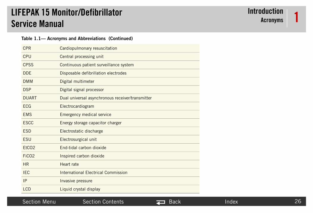
Joules
Display mode button
Home Screen button
CO2 exhaust
Input/output
Defibrillation-proof type CF patient connection
Defibrillation protected, type BF patient connection
Do not dispose of this product in the unsorted municipal waste stream.
Dispose of this product according to local regulations. See
www.physio-control.com/recycling for instructions on disposing of this
product.
2.1—Symbols (Continued)
l Description
J
CO2

LIFEPAService
SafetySymbols
Secti Index 39
2Table
Symbo
MIN
Rx On
K 15 Monitor/Defibrillator Manual
on Menu Section Contents Back
Mark of conformity to applicable European Directives
Canadian Standards Association certification for Canada and the
United States
Date of manufacture.
Authorized EC representative
Manufacturer’s identification number (part number)
Serial number
Reorder number
By prescription only
For USA audiences only
2.1—Symbols (Continued)
l Description
YYYY
or PN
SN
REF
ly or Rx Only
!USA

LIFEPAService
SafetySymbols
Secti Index 40
2Table
Symbo
K 15 Monitor/Defibrillator Manual
on Menu Section Contents Back
Catalog number
Manufacturer
Indicates that a product complies with applicable ACA standards
Positive terminal
Negative terminal
Fuse
Battery
Static-sensitive device. Static discharge may cause damage.
2.1—Symbols (Continued)
l Description
CAT
N13571

LIFEPAService
SafetySymbols
Secti Index 41
2
Repor
Acces
Table
Symbo
K 15 Monitor/Defibrillator Manual
on Menu Section Contents Back
ts
Biphasic defibrillation shock
Pace arrow, noninvasive pacing
Pace arrow, internal pacing detection
QRS sense marker
Event marker
sories
Mark of conformity to applicable European Directives
Recognized component mark for the United States
2.1—Symbols (Continued)
l Description

LIFEPAService
SafetySymbols
Secti Index 42
2Table
Symbo
LO
K 15 Monitor/Defibrillator Manual
on Menu Section Contents Back
Recognized component mark for Canada and the United States
Complies with (USA) Federal Communications Commission regulations
Type BF patient connection
Lot number (batch code). YY (year) and WW (week) of manufacture.
Enclosure ingress protection code per IEC 60529
Warning, high voltage
CAUTION - FIRE HAZARD
Do not disassemble, heat above 100°C (212°F), or incinerate battery
CAUTION - FIRE HAZARD
Do not crush, puncture, or disassemble battery
Use By date shown: yyyy-mm-dd or yyyy-mm
2.1—Symbols (Continued)
l Description
T YYWW
IP44
or

LIFEPAService
SafetySymbols
Secti Index 43
2Table
Symbo
K 15 Monitor/Defibrillator Manual
on Menu Section Contents Back
Indoor use only
Item is latex free
Lead free
Dispose of properly
Store in a cool, dry location (0° to 50°C, 32° to 122°F)
Single use only
2 electrodes in 1 package
10 packages in 1 shelf-pak
5 shelf-paks in 1 case
2.1—Symbols (Continued)
l Description
35°C
15°C
95°F
59°F
50°C
0°C
122°F
32°F
LIFEPAService
SafetySymbols
Secti Index 44
2Table
Symbo
K 15 Monitor/Defibrillator Manual
on Menu Section Contents Back
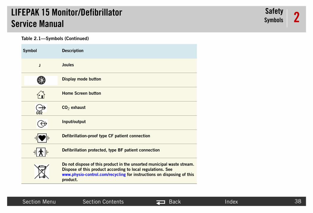
Shave patient skin
Clean patient skin
Treatment
Tear here
Press electrode firmly onto patient
Connect QUIK-COMBO cable
Slowly peel back protective liner on electrode
Do not use this pediatric QUIK-COMBO electrode on LIFEPAK 500,
LIFEPAK 1000, LIFEPAK CR® Plus, or LIFEPAK EXPRESS®
defibrillators
2.1—Symbols (Continued)
l Description

LIFEPAService
SafetySymbols
Secti Index 45
2Table
Symbo
K 15 Monitor/Defibrillator Manual
on Menu Section Contents Back
For use on adults
Not for use on adults
For use on children up to 15 kg (33 lb)
Not for use on children under 15 kg (33 lb)
Remove label from battery
Charge battery
Insert battery in LIFEPAK 15 monitor/defibrillator
Rechargeable battery
2.1—Symbols (Continued)
l Description

LIFEPAService
SafetySymbols
Secti Index 46
2
Shipp
Table
Symbo
K 15 Monitor/Defibrillator Manual
on Menu Section Contents Back
AC-DC power adapter
DC-DC power adapter
For use with the LIFEPAK 15 monitor/defibrillator
Power input
Power output
DC voltage
AC voltage
ing carton
This end up
2.1—Symbols (Continued)
l Description

LIFEPAService
SafetySymbols
Secti Index 47
2
S
Table
Symbo
K 15 Monitor/Defibrillator Manual
on Menu Section Contents Back
Fragile/breakable
Handle with care
Protect from water
Recommended storage temperature -20° to 60°C (-4° to 140°F)
Relative humidity range 10 to 95%
Recycle this item
2.1—Symbols (Continued)
l Description
or
Index
LIFEPAServic
Device DescriptionContents
48
3Device This section itor/defibrillator (device). Topics include input signals, asse
• In• P• D• S• Fu
Section Menu Back
K 15 Monitor/Defibrillatore ManualDescription describes the physical characteristics and functionality of the LIFEPAK 15 monmbly functions, and device outputs.
troduction (p. 49)hysical Description and Features (p. 54)evices, Options, Supplies, and Accessories (p. 65)ystem Context Diagrams (p. 70)nctional Descriptions (p. 74)
LIFEPAService
Device DescriptionIntroduction
Secti Index 49
3IntroductioThe introduct ing the following topics:
• Ab• De• En• Pa• In • Ma• De• Ass
AboutThe LI onse care, all the way from first responders to thro r option. The Version 2 (V2) device has the auxilia
DefibrThe de tion.
EnergThe de UIK-COMBO pacing/defibrillation/ECG electro usly measures the impedance between the electro to the patient. The user can select from a variety
K 15 Monitor/Defibrillator Manual
on Menu Section Contents Back
nion provides general information about the LIFEPAK Monitor/Defibrillator includ
out the Device (p. 49)fibrillation Waveform (p. 49)ergy Delivery (p. 49)cing Waveform (p. 50)AED Mode Operation (p. 50)nual Mode Operation (p. 50)vice Primary Functions (p. 50)emblies (p. 52)
the DeviceFEPAK 15 monitor/defibrillator provides innovative solutions for emergency respughout the hospital. The Version 1 (V1) device does not have the auxiliary powery power option.
illation Waveformvice generates a biphasic truncated exponential (BTE) shock pulse for defibrilla
y Deliveryvice standard method of defibrillation energy delivery is through self-adhesive Qdes. When using these disposable electrodes (DDEs), internal circuitry continuodes and allows defibrillation only when the defibrillation electrodes are attached of optional accessories for energy delivery (for example, hard paddles).

LIFEPAService
Device DescriptionIntroduction
Secti Index 50
3PacinThe de
In AEDIn the , which allows the Shock Advisory System (SAS) ws a prompted protocol for administering defibri rating instructions.
ManuIn Man direct current defibrillator that applies a brief, interpretation of the ECG rhythm and interac out Manual mode, see section 5 in the operat
DevicThe de
• De
• No
• Pa
K 15 Monitor/Defibrillator Manual
on Menu Section Contents Back
g Waveformvice generates a Monophasic, truncated exponential current pulse.
Mode OperationAED mode, see AED Mode (p. 91), the operator is prompted to press ANALYZEto analyze the ECG rhythm and make recommendations. The operator then follollation therapy. For more information about AED mode, see section 5 in the ope
al Mode Operationual mode, see Manual Mode (p. 90), the LIFEPAK 15 monitor/defibrillator is a
intense pulse of electricity to the heart muscle. Manual mode requires operator tion with the device in order to defibrillate the patient. For more information abing instructions.
e Primary Functionsvice has six primary functions:
fibrillation~ Manual or semi-automatic (AED) defibrillation~ Leads-off detection for therapy and ECG electrodes~ Synchronized cardioversion
ninvasive pacing~ Demand and non-demand modes of operation
tient information capturing~ Stores both patient and device data at each event~ Real-time clock provides time stamps for events

LIFEPAService
Device DescriptionIntroduction
Secti Index 51
3
• Pa
splay) g if one or both parameters are above alarm
play)rm display) when parameter is over alarm threshold) is canceled.en parameter is over alarm threshold) Note: celed.ges up to 8 hours.y for time ranges up to 8 hours.in V2-equivalent devices.
• 12
• Ala
K 15 Monitor/Defibrillator Manual
on Menu Section Contents Back
~ Provides operator review of stored events for printout or transmission~ Captures up to 360 minutes of continuous ECG data~ Continuous printing of ECG data
tient signal monitoring~ ECG monitoring — displays up to three ECG waveforms simultaneously~ Pulse oximetry (SpO2) monitoring (continuous numeric and waveform di
NOTE: SpO2 numeric display will be replaced by SpCO and/or SpMet readinthreshold.
~ Heart rate/pulse rate monitoring (continuous numeric display)~ Noninvasive blood pressure (NIBP) monitoring (numeric display)~ Invasive pressure (IP) monitoring (continuous numeric and waveform dis~ Capnography (CO2 and RR) monitoring (continuous numeric and wavefo~ Carboxyhemoglobin (SpCO) monitoring (continuous numeric is displayed
Note: numeric display will revert to SpO2 reading when alarm condition ~ Methemoglobin (SpMet) monitoring (continuous numeric is displayed wh
numeric display will revert to SpO2 reading when alarm condition is can~ Vital Signs Trend — Vital signs can be displayed graphically for time ran~ ST Trend — 12-lead ECG ST measurements can be displayed graphicall~ Temperature monitoring (numeric display). This feature is only available
-lead ECG capture and analysis~ Acquires, analyzes, and automatically prints 12-lead data
rms and warnings management~ Ventricular fibrillation/ventricular tachycardia monitoring and alarm~ Places alarm limits on patient monitoring parameters~ Automatic alarm limit reset at operator request~ Activates or suspends alarms and stores alarm events~ Silences alarms for up to 15 minutes~ Visual indicators and audible tones in alarm conditions

LIFEPAService
Device DescriptionIntroduction
Secti Index 52
3Servic
AssemThe de
Printe
• A0• A0• A0• A0• A0• A0
K 15 Monitor/Defibrillator Manual
on Menu Section Contents Back
e features include calibration and diagnostic functions.
bliesvice consists of a two-piece case assembly that encloses the following:
d Circuit Boards (when fully configured with options)
1 System PCB3 Power PCB4 Therapy PCB5 Interface PCB6 OEM PCB7 Contact PCB
• A08 Backlight PCB• A16 SpO2 Module • A21 NIBP Module• A22 Biphasic Module • A23 CO2 Module

LIFEPAService
Device DescriptionIntroduction
Secti Index 53
3Subas
See th able interconnect information and provides links t
• A0• A1• A1• A1• A1• A1• A1• A1• W• W
K 15 Monitor/Defibrillator Manual
on Menu Section Contents Back
semblies and Wire Harnesses
e Interconnect Diagram (Figure 9.2 on p. 370)—shows detailed assembly and co each part diagram. (p. 368).
9 Printer Control Keypad0 Main Keypad1 LCD Assembly 2 Printer Assembly3 Transfer Relay Assembly4 Inductive Resistor5 Energy Storage Capacitor7 Interconnect Bracket
07 ECG Connector Cable08 System Connector Cable
• W09 Auxiliary Connector Cable• W11 Therapy Connector Cable• W15 Speed Dial Assembly • W17 Speaker Assembly • W22 SpO2 Connector Cable• W28 CO2 Inlet Connector Cable• W33 Invasive Pressure Cable• W35 Temperature Cable

LIFEPAService
Device DescriptionPhysical Description and Features
Secti Index 54
3Physical DRefer to this
• Fro• Re• Wh
K 15 Monitor/Defibrillator Manual
on Menu Section Contents Back
escription and Featurestopic for a description and list of features for the following:
nt Panel (p. 55)ar Panel (p. 62)at Is Shipped with a Basic Device (p. 64)

LIFEPAService
Device DescriptionPhysical Description and Features
Secti Index 55
3FrontThis se e front panel. Select the area to view on Figure
Area 1 3.2 (p. 56)
Area 2Figure 3.3 (p
K 15 Monitor/Defibrillator Manual
on Menu Section Contents Back
Panelction provides information about buttons, indicator LEDs, and connectors on th
3.1 on p. 55
Figure 3.1—Front panel
CO2
SpO2
NIBP
ECG
P1
P2
Figure. 60)

LIFEPAService
Device DescriptionPhysical Description and Features
Secti Index 56
3Click t Figure 3.3 (p. 60).
ON
ENERGY SELECT
CHARGE
14
15
16
17
18
19
20
21
22
23
PACER
RATE
CURRENT
PAUSE
K 15 Monitor/Defibrillator Manual
on Menu Section Contents Back
he appropriate number below to view a description of that feature. See area 2 in
Figure 3.2—Front panel area 1
ALARMS
OPTIONS
EVENT
HOME SCREEN
CPR
SIZE
ANALYZE
LEAD
1
45678
9
10
1112
13
NIBP
SYNC
0
2
3

LIFEPAService
Device DescriptionPhysical Description and Features
Secti Index 57
3
Table
Numb
0
1 ervice Log (accessed in the Service/Status ng (p. 98) for information about error codes.
2 re fully charged. LED flashes when either attery is unable to be charged.
3 ted to auxiliary AC or DC power source, whether
4 en metronome function is active.
5 ED mode. The LED is illuminated when the SAS
6
7
8 mode. The LED is illuminated when active.
9 illuminated when BP measurement is being
1 is illuminated when alarms are enabled and
K 15 Monitor/Defibrillator Manual
on Menu Section Contents Back
3.1— Front Panel Area 1 Features
er Description
VF dose label — Physio-Control recommended energy dose for adultVentricular Fibrillation (VF)
Service LED — Illuminates when service error codes are written into the Smenu, see Displaying the Service/Status Submenu (p. 106)). See Troubleshooti
Battery charging indicator (V2 only) - LED illuminated when installed batteries abattery is charging. LED is not illuminated when no batteries are installed or a b
Auxiliary power indicator (V2 only) - LED illuminated when defibrillator is connecdefibrillator is turned on or off.
button and LED — Controls CPR metronome. LED is illuminated wh
button and LED — Activates the Shock Advisory System (SAS) in Ais active and flashes when user is prompted to press ANALYZE.
button — Changes ECG size.
button — Changes ECG lead or lead set.
button and LED — Activates synchronized cardioversion in Manual When synchronized, the LED flashes with each detected QRS complex.
button (optional) — Initiates blood pressure measurement. LED is obtained.
0 button and LED — Open alarms menu or silences alarms. The LEDflashes when an alarm condition occurs.
CPR
ANALYZE
SIZE
LEAD
SYNC
NIBP
ALARMS

LIFEPAService
Device DescriptionPhysical Description and Features
Secti Index 58
3
1 s are: PATIENT, PACING, DATE/TIME, ALARM
1
1 s menu.
1 ON. Press and hold to turn device off.
1 mode. Energy levels are from 2 joules to
1 or hard paddles must be attached. When the device is in pacing mode, pressing this
1 ther AED mode or Manual mode. The LED ssing both SHOCK buttons on the paddles
1 function is activated and flashes with each
1 s on button adjusts the pacing rate in 10 ppm s.
2 arrows on button adjusts the pacing current in ncrements.
Table
Numb
K 15 Monitor/Defibrillator Manual
on Menu Section Contents Back
1 button — Accesses optional functions. The options menu selectionVOLUME, ARCHIVES, PRINT, and USER TEST.
2 button — Accesses pre-defined and user-defined events.
3 HOME SCREEN button — Returns to Home Screen display or to previou
4 button and LED — Turns device ON or OFF. LED illuminated when
5 button — Increase or decrease defibrillator energy level in Manual 360 joules.
6 button — Charges the defibrillator in Manual mode. QUIK-COMBOoperating with hard paddles, use the CHARGE button on the APEX paddle. Ifbutton deactivates Pacing Mode and charges the device.
7 SHOCK button and LED — Initiates discharge of defibrillator energy in eiflashes when the device is fully charged. When operated with hard paddles, predischarge energy.
8 button and LED — Activates pacer function. LED illuminated whencurrent pulse.
9 button — Increases or decreases pacing rate. The up or down arrowincrements, or rotate the SPEED DIAL to change the rate in 5 ppm increment
0 button — Increases or decreases pacing current. The up or down10 mA increments, or rotate the SPEED DIAL to change the current in 5 mA i
3.1— Front Panel Area 1 Features (Continued)
er Description
OPTIONS
EVENT
ON
ENERGYSELECT
CHARGE
PACER
RATE
CURRENT

LIFEPAService
Device DescriptionPhysical Description and Features
Secti Index 59
3
2 ile pressed, PAUSED appears before PPM at
2 trast SunVue™ display.
2
Table
Numb
K 15 Monitor/Defibrillator Manual
on Menu Section Contents Back
1 button — Temporarily slows pacing rate to 25% of the set rate. Whthe bottom of the screen. Release to resume pacing at the set rate.
2 DISPLAY MODE button — Switches between color display and high con
3 SPEED DIAL — Scrolls through and selects screen or menu items.
3.1— Front Panel Area 1 Features (Continued)
er Description
PAUSE

LIFEPAService
Device DescriptionPhysical Description and Features
Secti Index 60
3Click t
12-LEAD
11 12
CO2
SpO2
NIBP
ECG
P1
P2
K 15 Monitor/Defibrillator Manual
on Menu Section Contents Back
he appropriate number to view a description of that feature.
Figure 3.3—Front panel area 2
CO2
SpO2
NIBP
ECG
P1
P2
1
2
3
4
5
10
SUMMARY
TRANSMIT
CODE
6789
12-LEAD
5

LIFEPAService
Device DescriptionPhysical Description and Features
Secti Index 61
3Table
Numb
1 ntinuously measures the amount of CO2 during
2 oximeter, which noninvasively checks the centration in arterial blood.
3 ure tubing which connects to the cuff. NIBP
4 e. Cable configurations include the 12-lead .
5 h invasively measure arterial blood pressures,
d by a single port labeled TEMP.
6 nting of a 12-lead ECG report.
7 through direct connect serial, gateway, or
8 including vital signs and waveforms.
9 rinting.
1
1
1 nd hard paddles.
K 15 Monitor/Defibrillator Manual
on Menu Section Contents Back
3.2— Front Panel Area 2 Features
er Description
CO2 FilterLine® set port (optional) — Intake port for the CO2 monitor, which coeach breath and reports the amount present at the end of exhalation (CO2).
SpO2/SpCO/SpMet sensor cable port (optional) — Connection port for the pulsesaturation of oxygen, carboxyhemoglobin concentration, and methemoglobin con
NIBP pneumatic tubing port (optional) — Port for connection to the blood pressmeasures the blood pressure of the adult or pediatric patient.
ECG cable port — Connection port for the electrically isolated ECG patient cablcable with limb lead and precordial lead attachments, 5-wire, and 3-lead cables
IP cable ports — P1 and P2 connection ports for invasive pressure cables, whiccentral venous pressure (CVP), or intracranial pressure.Note: If device is configured for temperature monitoring, P1 and P2 are replace
button (optional) — Initiates acquisition, analysis, storage, and pri
button — Initiates transmission of patient data to another locationwireless connection.
button — Prints a summary of the current patient documentation,
button — Prints a continuous ECG stripchart. Press again to stop p
0 Speaker — Projects device tones and voice prompts.
1 Printer — Prints displayed waveforms, CODE SUMMARY, and other reports.
2 Therapy cable receptacle — Connection point for QUIK-COMBO therapy cable a
12-LEAD
TRANSMIT
CODESUMMARY

LIFEPAService
Device DescriptionPhysical Description and Features
Secti Index 62
3 RearThis se
8
9
K 15 Monitor/Defibrillator Manual
on Menu Section Contents Back
Panel ction provides information about features on the rear panel.
Figure 3.4—Rear features diagram
2 1
1
2
3
7 56
10
4

LIFEPAService
Device DescriptionPhysical Description and Features
Secti Index 63
3Table
Numb
1
2
3
4
5
6
7
8
9
1
K 15 Monitor/Defibrillator Manual
on Menu Section Contents Back
3.3— Rear Panel Features
er Description
Hard paddle wells — Storage area for a set of hard paddles.
USB port cover — Protects USB port from the environment.
System connector — Connects device to a gateway or external computer for transfer of patient reports. Also provides real-time ECG output.
Auxiliary connector — Connection port for an external poweradapter.
Battery compartments — Accommodate two removable Lithium-ion batteries that provide power for the LIFEPAK 15 monitor/defibrillator.
Battery contacts — Transfer battery status information.
Battery pins — Two pins in each battery compartment transfer the battery power.
CO2 exhaust port (optional) — Vents gasses from CO2 monitor.
Paddle retainers — Provide secure retention and quick removal of paddles.
0 Paddle test contacts — Allow complete paddles defibrillation checks.

LIFEPAService
Device DescriptionPhysical Description and Features
Secti Index 64
3What A basi
QUIK-COMBO electrodes (2)
operating instructions
(2) rolls printer paper
(no picture)t Load — for use with QUIK-COMBO therapy cable
K 15 Monitor/Defibrillator Manual
on Menu Section Contents Back
Is Shipped with a Basic Devicec device includes the components shown below.
Figure 3.5—Components of the basic device
3-lead ECG cable
QUIK-COMBO therapy cable
LIFEPAK 15 monitor/defibrillator
Tes

LIFEPAService
Device Description, Options, Supplies, and Accessories
Secti Index 65
3Devices, O
The fo ies, and accessories that are available. For up-to- line at store.physio-control.com (U.S. only).
Table
Item
LIFEP
Basic
Optio
SpO2
MNC patient cable
SpO2/
CO2
K 15 Monitor/Defibrillator Manual Devices
on Menu Section Contents Back
ptions, Supplies, and Accessories llowing table, provided for reference, summarizes optional configurations, suppldate ordering information, contact your Physio-Control representative or order on
3.4— LIFEPAK 15 Configurations
Description
AK 15 monitor/defibrillator
device • 3-lead ECG cable• QUIK-COMBO therapy cable• Two sets QUIK-COMBO electrodes• Device operating instructions• 2 rolls of 100-mm printer paper
nal Features
(only) Accessories:• Masimo SET® Red™ or LNCS™ sensors• Masimo SET Red patient cables• Nellcor Oximax™ sensors with Masimo Red™
SpCO/SpMet Accessories:• Masimo SET Rainbow® sensors
Accessories:• Airway adapter• FilterLine®
• CapnoLine®

LIFEPAService
Device Description, Options, Supplies, and Accessories
Secti Index 66
3
NIBP
Vital s T measurement for up to 8 hours.
Invasi ecifications.
Tempe
12-lea
Blueto ol data management products
Option
Hard p(can bcable sync c
Pediat(attac
Table
Item
K 15 Monitor/Defibrillator Manual Devices
on Menu Section Contents Back
Accessories:• Reusable blood pressure cuff• Disposable blood pressure cuff• NIBP hose - coiled
igns and ST trending Provides graphical plot trending of vital signs or S
ve Pressure See the operating instructions for IP accessory sp
rature Accessories:• Disposable temperature probes• Temperature probe adapter cable
d ECG Accessories:• Main 4-wire cable• 6-wire precordial lead attachment
oth Provides wireless communication to Physio-Contr
al Therapy Delivery
addlese used instead of QUIK-COMBO and electrodes for defibrillation or ardioversion)
Pair
ric paddlesh to hard paddles
Two required
3.4— LIFEPAK 15 Configurations (Continued)
Description

LIFEPAService
Device Description, Options, Supplies, and Accessories
Secti Index 67
3
Electr
LIFE•(for m
QUIK-electro
Power
Batter
LIFEPor Mo
ws, 4 lock washers, and template
REDI-System
LIFEPpower
LIFEPpower
Table
Item
K 15 Monitor/Defibrillator Manual Devices
on Menu Section Contents Back
odes
PATCH ECG electrodes onitoring only)
Sets of 3 or 4
COMBO multifunctional ECG des with EDGE System™ technology
• Standard — one pair• Radio transparent system (RTS) — one pair• RTS, pediatric — one pair• REDI-PAK™ preconnect system — one pair
Options
ies (two per device) • Rechargeable Lithium-ion (with fuel gauge)
AK 15 monitor/defibrillator Station bile Li-ion Battery Charger
• AC power cord (country/region specific)• DC power cable (Mobile Charger only)• Mounting bracket with 4 (8-32 x 0.5”) scre
CHARGE™ Li-ion Battery Charging • LIFEPAK 15 Li-ion battery adapter tray• AC power cord (country/region specific)
AK 15 monitor/defibrillator AC adapter
• AC power cord (country/region specific)• Power adapter output cable• Optional - output extension cable
AK 15 monitor/defibrillator DC adapter
• DC power cord (unterminated)• Power adapter output cable• Optional - output extension cable
3.4— LIFEPAK 15 Configurations (Continued)
Description

LIFEPAService
Device Description, Options, Supplies, and Accessories
Secti Index 68
3
Data M
Cables s to serial port on a PC or other equipment) to USB connector on a PC or other equipment)CG waveforms on external equipment)
PC so um version required)
Traini
PatienECG feature)
Testerrapy cable only
Techn
Opera
Servic
Carry
Carryi ncludes left and right bags) with shoulder strap
Table
Item
K 15 Monitor/Defibrillator Manual Devices
on Menu Section Contents Back
anagement and Communications
• Device-to-PC serial interface cable (connect• Device-to-PC USB interface cable (connects• Analog ECG output cable (used to monitor E
ftware • CODE-STAT™ Reviewer, version 8.0 (minim• DT EXPRESS™ 3.0 Data Transfer Software
ng and Testing Tools
t simulators • QUIK-COMBO, 3-lead• QUIK-COMBO, 12-lead (used with 12-lead
s • Defibrillation checker for hard paddles• Test Load — for use with QUIK-COMBO the
ical Manuals
ting instructions • Printed, one included per device
e manual • CD-ROM
ing Bags
ng bags • Basic carrying bag system — device only (i• Shoulder strap• Rear bag — (screws into back of device)• Paddle well bag
3.4— LIFEPAK 15 Configurations (Continued)
Description

LIFEPAService
Device Description, Options, Supplies, and Accessories
Secti Index 69
3
Suppl
Printe
SIGNA
Table
Item
K 15 Monitor/Defibrillator Manual Devices
on Menu Section Contents Back
ies
r paper • 100-mm printer paper — box of 2 rolls
GEL® electrode gel • Use with hard paddles
3.4— LIFEPAK 15 Configurations (Continued)
Description

LIFEPAService
Device DescriptionSystem Context Diagrams
Secti Index 70
3System Co
Refer ted. The diagrams include the following:
• Fro• De
K 15 Monitor/Defibrillator Manual
on Menu Section Contents Back
ntext Diagramsto this section to view diagrams of how the major parts of the system are connec
nt of Device (p. 71)vice Communication (p. 73)

LIFEPAService
Device DescriptionSystem Context Diagrams
Secti Index 71
3FrontThe fo
QUIK-COMBO therapy cable (QUIK-COMBO
electrodes)hard paddles
K 15 Monitor/Defibrillator Manual
on Menu Section Contents Back
of Devicellowing diagrams illustrate how the device connects to external accessories.
Figure 3.6—Device connections with external equipment and accessories
Invasive Pressure (P1 & P2) or Temperature (T1)
(see next page)printerpaper
12-lead ECG cable
3-lead or 5-wire
ECG cable
SpO2 cable
finger sensor
main 4-wire cable
precordial lead
attachment
CO2 tubing
NIBP tubing
3-pack ECG electrodes

LIFEPAService
Device DescriptionSystem Context Diagrams
Secti Index 72
3The fo erature equipment.
t
AccTemp
MeaSpecialtdisposab
K 15 Monitor/Defibrillator Manual
on Menu Section Contents Back
llowing diagram illustrates how the device connects to invasive pressure or temp
Figure 3.7—Device connection with invasive pressure or temperature equipmen
P1 and P2 connection - OEM invasive pressure
adapter cable
examples of OEM invasive pressure
transducers
P2Temperature or P1
essory cable - erature adapter
cable
surement ies 4400 Series le temperature probe

LIFEPAService
Device DescriptionSystem Context Diagrams
Secti Index 73
3Devic
B
K 15 Monitor/Defibrillator Manual
on Menu Section Contents Back
e Communication
Figure 3.8—Device system connector
luetooth radio is integrated onto the Interface PCB
LIFEPAService
Device DescriptionFunctional Descriptions
Secti Index 74
3FunctionalThe LIFEPAK ning a variety of therapeutic and monitoring features. In a acing, the device offers optional oximetry, invasive pressure, non feature of the device is its ability to be upgraded as the needs of is powered by two Lithium-ion batteries.
The functiona d assist the qualified service technician in troubleshooti de the factory, is not recommended, nor is it within the scope of
See the syste ing functional descriptions.
• Sys• Po• Th• OE• Co• Ba• Pri• LC• Pri• Tra• Ind• En• Sp• Int• NIB• Bip• CO
K 15 Monitor/Defibrillator Manual
on Menu Section Contents Back
Descriptions15 monitor/defibrillator (device) is a platform medical device capable of combi
ddition to manual defibrillation, semiautomatic defibrillation, and noninvasive pinvasive blood pressure, CO2, 12-lead ECG, and temperature monitoring. A key the customer change or as new features become available. This portable device
l descriptions that follow provide a basic understanding of the device design anng to the subassembly level. Troubleshooting below the subassembly level, outsithis service manual to provide the detail necessary to support such repairs.
m block diagram (Figure 3.9 on p. 76) when necessary as you review the follow
tem PCB (A01) (p. 77)wer PCB (A03) (p. 79)erapy PCB (A04) (p. 80)M PCB (A06) (p. 83)ntact PCB (A07) (p. 84)cklight PCB (A08) (p. 84)nter Control Keypad (A09)/Main Keypad (A10) (p. 84)D Assembly (A11) (p. 84)nter Assembly (A12) (p. 84)nsfer Relay Assembly (A13) (p. 85)uctive Resistor (A14) (p. 85)ergy Storage Capacitor (A15) (p. 85)O2/SpCO/SpMet Module (A16) (p. 85)erconnect Bracket (A17) (p. 85)P Module (A21) (p. 86)hasic Module (A22) (p. 86)2 Module (A23) (p. 86)

LIFEPAService
Device DescriptionFunctional Descriptions
Secti Index 75
3• EC• Sys• Th• Sp• Sp• Sp• CO• IP • Tem
K 15 Monitor/Defibrillator Manual
on Menu Section Contents Back
G Connector Cable (W07) (p. 86)tem Connector Cable (W08) (p. 86)
erapy Connector Cable (W11) (p. 87)eed Dial Assembly (W15) (p. 87)eaker Assembly (W17) (p. 87)O2 Connector Cable (W22) (p. 87)2 Inlet Connector Cable (W28) (p. 88)Connector Cable (W33) (p. 88)perature Connector Cable (W35) (p. 88)

LIFEPAService
Device DescriptionFunctional Descriptions
Secti Index 76
3
Figure 3.9—S
BiphModule
TransAssem(A13)
TheraConnCable
Batt #1
Contact PCB (A07)
Batt #2
Inte
rcon
nect
Bra
cket
(A
17)
end
r
r
LCD backlight converter
ECG Connector Cable (W07)
Printer Assembly
(A12)LCD
Assembly (A11)
Backlight PCB (A08)
Printer Control Keypad (A09)/
Printer Control Keypad (A09)/
LED driver
Keypad row driver
d ut
lock/ RAM
AM)
rd
Audio amplifier
Speed Dial Assembly (W15)
Speaker Assembly (W17)
System Connector Cable (W08)
Keypad column receiver
Interface PCB (A05)
EnergStoragCapac(A15)
Auxiliary Power
Connector Cable (W09)
Bluetooth Radio
K 15 Monitor/Defibrillator Manual
on Menu Section Contents Back
ystem block diagram
asic (A22)
IP Connector Cable (W33)
IP / Temperature
front end
Powerswitching
ON/OFFcontrol
Powerprocessor
Powersupplies
SpO2 Connector Cable (W22)
SpO2/SpCO/SpMet Module
(A16)
OEM PCB (A06)
fer Relay bly
Dump relay control
Transfer relay control
QUIK-COMBO leads-off (impedance
Paddles/QUIK-COMBO ECG
Defibrillator processor
Paddles/pacer processor
py ector (W11)
Noninvasive pacemaker
Energy storage capacitor charger
ECG front
Printer controlle
Displaycontrolle
Combineaudio outp
Real-time cnon-volatile(RTC/NVR
System connector interface
Single-BoaComputer (SBC)
Fiel
d-Pr
ogra
mm
able
Gat
e Ar
ray
(FPG
A) a
nd A
pplic
atio
n-Sp
ecifi
c In
tegr
ated
Circ
uit (
ASIC
)
CO2 Inlet Connector Cable
(W28)
CO2 Module (A23)
NIBP Module (A21)
Temperature Connector
Cable (W35)
System PCB (A01)Power PCB (A03)
Therapy PCB (A04)
y e itor

LIFEPAService
Device DescriptionFunctional Descriptions
Secti Index 77
3SysteThe A0 primary components:
) for intensive number-processing tasks.
ircuit (ASIC)ircuit (ASIC) operate as the interface display device subsystems.
The fo asic functions.
er PCB (via the A04 Therapy PCB) to
, ASIC, and audio subsystems, and the A04
FPGA CPUs, DSP, main, and ASIC
CB.
connected leads for use in the interpretive functions of patient isolation, electrostatic width filtering, internal pacemaker
K 15 Monitor/Defibrillator Manual
on Menu Section Contents Back
m PCB (A01)1 System PCB integrates and controls all functions of the device. There are two
Single-Board Computer (SBC)The single board computer (SBC) functions as the central processing unit (CPU
Field-Programmable Gate Array (FPGA) and Application-Specific Integrated CThe field-programmable gate array (FPGA) and application-specific integrated cbetween the CPU and all other therapeutic, monitoring, data management, and
llowing items identify the major subsystems of the A01 System PCB and their b
Power suppliesThe A01 System PCB uses SW_VB (switched battery voltage) from the A03 Poworiginate six power supplies for use throughout the device as follows:
~ +1.5 V power for use on the FPGA.~ +1.8 V power for use on the SBC.~ +5 V logic power for use on the A01 System PCB within the DUART, RTC
Therapy PCB.~ +3.3 V logic power for use on the A01 System PCB within the SBC and
subsystems.~ ±12 V analog power for use on the A01 System PCB and A04 Therapy P~ +24 V power for use in the A01 System PCB printer subsystem.
ECG front end The device simultaneously captures inputs from up to 10 independent patient-12-lead algorithm and ECG waveform display. The ECG front end performs the discharge and defibrillation protection, lead selection, baseline dc restore, band

LIFEPAService
Device DescriptionFunctional Descriptions
Secti Index 78
3m the ADC process pass across the isolation ignal conditioning before being used by the e.
IP transducer through the IP input r simultaneous monitoring of two IP parameter bezel to the A01 System PCB,
mplifier iso-barrier. The transducer drive resistive bridge-type transducer. The output instrumentation amplifier, which amplifies onverter, digitized, and then sent serially
re probe through the external adapter cable. ctor on the parameter bezel. The W35 to the A01 System PCB.
controller governs motor speed, adjusts print emperature, and provides the data to be PCB.
ser setups. The RTC/NVRAM is powered by a
K 15 Monitor/Defibrillator Manual
on Menu Section Contents Back
detection, and ECG sampling via analog-to-digital conversion (ADC). Results frobarrier to the A01 System PCB digital signal processor (DSP) for filtering and sSBC CPU. ECG input is through the parameter bezel W07 ECG Connector Cabl
IP / Temperature front endThe invasive pressure (IP) circuitry processes the input signal from a disposableconnectors on the device parameter bezel. Two input connectors are provided fochannels. The W33 Invasive Pressure Harness provides the connection from thewhere the IP/temp preamplifier circuitry is located. The IP/temp preamplifier is isolated from the AC power ground by the ECG preacircuitry supplies a positive 2.5 V and a negative 2.5 V excitation voltage to thesignal from the transducer is conditioned by a low-pass filter at the input of an the signal approximately 400 times. The signal is then multiplexed to the A-D cacross the iso-barrier for DSP processing and display.The temperature circuity processes the input signal from a disposable temperatuThe temperature adapter cable connects to the connector below the ECG connetemperature connector cable provides the connection from the parameter bezel
Printer controllerThe device uses a 100-mm thermal array printer. The A01 System PCB printer strobe pulse width, senses paper presence and door closure, senses printhead tprinted. Printer fonts are stored in memory devices located on the A01 System
Real-time clock/non-volatile RAM (RTC/NVRAM)The RTC/NVRAM maintains the date and time and provides storage for device ulithium coin cell battery.

LIFEPAService
Device DescriptionFunctional Descriptions
Secti Index 79
3
signal output, data transmission, factory g field upgrade. Except for analog ECG
cluding a digital-to-analog converter (DAC),
nts:
evels.
m PCB Display Controller made up of a memory devices located on the A01 System
larm tones) from the ASIC returns to analog 5 Interface PCB audio amplifier for
devices located on the A01 System PCB.
PoweThe A0 atteries. Additional functions include power on/off y voltage measurement, over-current protec
A03 P ce of available power sources, selects a power , replace battery, removal from the device, etc.) a when connected.
K 15 Monitor/Defibrillator Manual
on Menu Section Contents Back
System connector interface The device can be connected to external equipment for transmitting analog ECGtest, Physio-Control field service data collection, and device configuration durinsignals, all data communication at the system connector is at RS-232 levels.The analog ECG signal output path consists of A01 System PCB components, inlow-pass filter, and electrostatic discharge protection.The digital communications output path consists of the following two compone
~ Dual universal asynchronous receiver/transmitter (DUART)~ Level-shifter, used for converting device internal logic levels to RS-232 l
Display controllerData for display on the device A11 LCD assembly originates from the A01 Systeportion of the SBC and dedicated data driver/buffers. Screen fonts are stored inPCB.
Combined audio outputOriginates from the A01 System PCB ASIC. System audio (voice prompts and aform in an A01 System PCB DAC. System audio is filtered and routed to the A0application to the W17 Speaker Assembly. Voice prompts are stored in memory
r PCB (A03)3 Power PCB manages application of power to the device from the two Li-ion b
control, “smart” battery communication, routing battery charge currents, battertion fusing, and serial communication of power status to the A01 System PCB.
ower PCB operation centers around a power processor, which detects the presensource for use by the device, and monitors their status (for example, low batterynd can apply charging currents from an attached power adapter to the batteries

LIFEPAService
Device DescriptionFunctional Descriptions
Secti Index 80
3When circuitry to alert the power processor, which choose W_VB is then routed, in turn, to the A04 Therap m power supply voltages.
Closur n prior to turning off SW_VB.
TheraThe A0 ition to developing defibrillation and noninv gies, captures ECG paddles, and monitors attach
The m s:
functions using serial inputs from the A01 er A04 Therapy PCB circuitry. Status of the
on battery voltage) to high voltage for comparisons between stored energy and uits compensate the ESCC for low battery es to separate safety monitoring and energy
control signals from the SHOCK button (or System PCB ASIC. The transfer relay will be ns are satisfied in each system component.
K 15 Monitor/Defibrillator Manual
on Menu Section Contents Back
the device is OFF, closure of the device power control activates A03 Power PCBs the appropriate source to originate SW_VB (switched battery voltage) power. Sy PCB and A01 System PCB for use, as is, and for further processing into syste
e of the power control when the device is ON triggers an orderly device shutdow
py PCB (A04)4 Therapy PCB maintains the patient interface for therapeutic purposes. In addasive pacing energies, the A04 Therapy PCB ensures safe delivery of those enerment of the QUIK-COMBO electrodes.
ajor subsystems of the A04 Therapy PCB and their basic functions are as follow
Defibrillator processorThe defibrillator processor manages the defibrillator energy storage and deliverySystem PCB ASIC, hardware inputs from external paddles, and inputs from othdefibrillator subsystem is reported serially to the A01 System PCB ASIC.
Energy storage capacitor charger (ESCC)Under control of the defibrillator processor, the ESCC converts COM_VB (commapplication to the energy storage capacitor. Circuitry within the ESCC performs target energy to limit charging to the value selected by the user. Additional circvoltage, provide over-voltage protection, and send divided capacitor high voltagdisplay circuits.
Transfer relay controlTo enable the transfer of defibrillation energy, the A04 Therapy PCB integrates external paddles’ SHOCK buttons), defibrillator processor, ESCC, and the A01activated only to deliver energy to the defibrillation electrodes when all conditio

LIFEPAService
Device DescriptionFunctional Descriptions
Secti Index 81
3
y storage capacitor under a number of activation, and QUIK-COMBO leads-off). nder the control of the system and/or
ff/motion detection circuits are active. Only s applied. ent system as a simple voltage divider.
an 125 k
l through the QUIK-COMBO electrodes into atient. Minute perturbations sensed in the ges in the sensed signal indicate electrode
ent isolation, electrostatic discharge and aker detection, and ECG sampling through
paddles/pacer processor.
K 15 Monitor/Defibrillator Manual
on Menu Section Contents Back
Dump relay controlA fail-safe system used to safely dissipate defibrillation energies from the energcircumstances (for example, change of energy selection, power removal, pacingWith the exception of power removal, the dump relay control system functions udefibrillator processors.
QUIK-COMBO leads-off (impedance sense/motion detection)With the QUIK-COMBO electrodes applied and the device in AED mode, leads-oleads-off is active when device is in Manual mode and QUIK-COMBO electrodeFor purposes of this discussion, consider the leads-off/motion detector and patiLeads-off/motion detection relies on two main characteristics:
~ Leads-off/motion detector output impedance is relatively high (greater th~ Patient impedance is relatively low (typically less than 30 ).
To exploit these characteristics, the device injects an ac impedance drive signathe relatively low patient impedance and monitors the voltage drop across the plow-amplitude signal developed across the patient represent motion; gross chandisconnection.
Paddles/QUIK-COMBO ECG preamplifierThe ECG paddles/QUIK-COMBO ECG preamplifier perform the functions of patidefibrillation protection, baseline dc restore, bandwidth filtering, internal pacemanalog-to-digital conversion (ADC). Results from the ADC process are fed to the

LIFEPAService
Device DescriptionFunctional Descriptions
Secti Index 82
3
tion and paddles ECG signal acquisition. trols to enable noninvasive pacemaker rom the Paddles/QUIK-COMBO ECG er to the A01 System PCB DSP and onto the
justable current, 20-millisecond (nominal), acemaker include the paddles/pacer t current, pulse width, and pulse shape tween the paddles/pacer processor and the
InterfThe A0 uting of cables between the front and rear halves into the W04 System PCB/Interface PCB Cable nents (for example, A09 Printer Control Keypa wing active circuits reside on the A05 Interfa
PCB Audio Amplifier prior to application to
K 15 Monitor/Defibrillator Manual
on Menu Section Contents Back
Paddles/pacer processorThe paddles/pacer processor controls all facets of noninvasive pacemaker operaInputs received serially from the A01 System PCB ASIC are translated into condelivery of properly timed pacing impulses at the desired current. Analog ECG fPreamplifier is processed for local use and for transfer across the isolation barriA01 System PCB ASIC.
Noninvasive pacemakerThe A04 Therapy PCB noninvasive pacemaker subsystem develops isolated, adtrapezoidal transchest pacing impulses. Major components of the noninvasive pprocessor, isolated low- and high-voltage power supplies, safety monitors, outpucontrols. Controls for, and status of, the noninvasive pacemaker pass serially beA01 System PCB ASIC.
ace PCB (A05)5 Interface PCB is primarily a signal collector/distributor used to simplify the ro
of the device. The majority of signals from the device rear half are consolidatedand passed to the A05 Interface PCB for further distribution to front half compod, A10 Main Keypad, A11 LCD Assembly, and A12 Printer Assembly). The folloce PCB:
Audio amplifierCombined audio output signals receive final amplification in the A05 Interface the W17 Speaker Assembly.
LIFEPAService
Device DescriptionFunctional Descriptions
Secti Index 83
3
erial-to-parallel converter located on the A05 . The CHARGE and Power ON LEDs receive
n address scheme (that is, each button into the A05 Interface PCB Keypad Row rinter control keypad and A10 main keypad. ad column receiver.
ypad column receiver (a parallel-to-serial on to one, and only one, column receiver
ly a minimum of 9.6 V to the A08 Backlight display controller. A separate backlight
and archived data from the LIFEPAK 15 -STAT™ or DT EXPRESS™ software.
OEM PA PCB or original equipment manufacturers (OEMs er supplies, safety isolation, transient protec
K 15 Monitor/Defibrillator Manual
on Menu Section Contents Back
LED driverMost device LEDs (located on the A10 main keypad) receive their drive from a sInterface PCB. The Service LED drive originates from the A01 System PCB ASICtheir drive from the A03 Power PCB Power Processor.
Keypad row driver The A01 System PCB ASIC reads device control buttons using a row and columresides at a unique row and column address). Data from the ASIC shifts seriallyDriver (a serial-to-parallel converter) for application to button rows in the A09 pA button closure enables row drive for a unique button to be sensed at the keyp
Keypad column receiverThe A01 System PCB ASIC reads button closures serially from the Interface keconverter). In practice, closure of a device button passes row drive for that buttinput.
LCD backlight converterThe A05 Interface PCB applies filtered SW_VB through a Boost Converter to appPCB when it receives an enable signal (LCD_BL_ON) from the A01 System PCBpower supply is mounted on a metal bracket in the front case.
Bluetooth RadioBluetooth radio is integrated onto the Interface PCB. You can transmit current device to the LIFENET® System or to post-event review products such as CODE
CB (A06) used to integrate monitoring modes supplied to Physio-Control by third parties,), into the device system architecture. The A06 OEM PCB provides isolated powtion, and signal interface adapters to support hosted OEM modules.

LIFEPAService
Device DescriptionFunctional Descriptions
Secti Index 84
3ContaInterfa ication to and from the battery. In addition, the de
BacklA prin n.
PrinteComm ugh either the A09 printer control keypad or the A1 he features installed in a specific device. All button tion of the A01 System PCB ASIC.
• Th to activate and deactivate the device without AS /Off control block.
• Th il-safe design, thus preventing inappropriate act e SHOCK button are applied in two places: the ltimate shock decision rests with both the AS
LCD AA back aveforms and text messages.
PrinteThe 10 ultiple displayed waveforms.
K 15 Monitor/Defibrillator Manual
on Menu Section Contents Back
ct PCB (A07)ces the Li-ion battery edge connector with the device and provides I2C communvice uses a battery pull signal to indicate when the battery is being removed.
ight PCB (A08)ted circuit board that contains the circuitry to light the A11 LCD assembly scree
r Control Keypad (A09)/Main Keypad (A10)on device controls (those not available using the SPEED DIAL) are initiated thro0 main keypad. The number of buttons on these keypads varies, depending on ts, with the exception of ON and SHOCK, are addressed by the user controls sec
e ON button remains separate from the addressed buttons because it is needed IC interaction. Closures of the ON button are applied to the A03 Power PCB One SHOCK button remains separate from the addressed buttons as a matter of faivation under conditions of loss of CPU control. Operator-initiated closures of th A01 System PCB ASIC and the A04 Therapy PCB defibrillator processor. The uIC and defibrillator processor agreeing to deliver defibrillation energy.
ssembly (A11)lit, 640 × 480 pixel, color LCD that displays the primary and secondary ECG w
r Assembly (A12)0-mm printer is installed to support 12-lead ECG monitoring and printing of m

LIFEPAService
Device DescriptionFunctional Descriptions
Secti Index 85
3TransA high Storage Capacitor, by means of the A22 Biphas of the A13 Transfer Relay is governed by the A04 T
InducA resis gulator circuit on the A22 Biphasic Module.
EnergA meta y Storage Capacitor is calculated when you perform 5 μF.
SpO2/An OE ted to oxygen, carboxyhemoglobin and methe y means of the A06 OEM PCB to the A01 System
IntercA term asic Module, and A15 Energy Storage Capac rge cable tie.
K 15 Monitor/Defibrillator Manual
on Menu Section Contents Back
fer Relay Assembly (A13)-voltage relay mounted in the rear case that routes current from the A15 Energyic Module, through the W11 Therapy Connector Cable to the patient. Activation herapy PCB Transfer Relay Control block.
tive Resistor (A14)tor that conditions the energy storage capacitor output for the wave generator/re
y Storage Capacitor (A15)llized film capacitor used for energy storage. The capacitance of the A15 Energ the TCP – Defibrillator Energy Calibration procedure. The nominal value is 19
SpCO/SpMet Module (A16)M oximetry module supplied by Masimo. The module performs all functions relamoglobin saturation, including sensor drive. Measurement results pass serially b PCB ASIC for display.
onnect Bracket (A17)inal assembly used to interconnect the A13 Transfer Relay Assembly, A22 Biphitor. The bracket itself is strapped to the A15 Energy Storage Capacitor with a la

LIFEPAService
Device DescriptionFunctional Descriptions
Secti Index 86
3NIBP An OE pressure monitoring, determining systolic, diasto ns of the A06 OEM PCB to the A01 System PCB A
BiphaThe bi ge Capacitor is shaped into the biphasic wavefo lay to the W11 Therapy Connector.
CO2 MAn OE sly monitors end-tidal carbon dioxide (CO2) and re to the A01 System PCB ASIC for display.
ECG CA fron . Signal processing takes place on the A01 System
SysteA rear al modem, personal computer, factory test system ies a real-time analog ECG signal for use in basic c
AuxiliA rear
K 15 Monitor/Defibrillator Manual
on Menu Section Contents Back
Module (A21)M NIBP monitor supplied by CAS Medical Systems. This module performs bloodlic and mean pressures and pulse rate. Measurement results pass serially by meaSIC for display. Readings may be taken one time or on a recurring interval.
sic Module (A22)phasic module generates the biphasic waveform. The energy from the A15 Storarm. The energy passes through the A14 Inductive Resistor and A13 Transfer Re
odule (A23)M capnometry module supplied by Oridion Medical Ltd. This module continuouspiratory rate. Measurement results pass serially by means of the A06 OEM PCB
onnector Cable (W07)t panel connector port used for attaching a 3-lead, 5-wire, or 12-lead ECG cable
PCB ECG front end processing circuitry (see ECG front end (p. 77)).
m Connector Cable (W08)panel connector port used for the exchange of digital information with an externs, or Physio-Control field service test systems. The system connector also supplentral monitoring or telemetry systems.
ary Power Connector Cable (W09)panel access port used for connection of external power adapters.

LIFEPAService
Device DescriptionFunctional Descriptions
Secti Index 87
3TheraA patie energies. The therapy connector allows attach brillation/ECG electrodes, and adult hard paddle
NOTE ts connect to the device by means of the
The LI ed accessories to determine the type of access processor subsystem decodes the accessory jumpe
SpeedA rotar s from the LIFEPAK 15 monitor/defibrillator menu When the desired item has been highlighted on the IAL forms part of the user controls and indica user controls portion of A01 System PCB ASIC.
SpeakUsed t Drive for the W17 Speaker Assembly origina ccurs in the A05 Interface PCB audio amplif
SpO2 A fron eter) sensor.
K 15 Monitor/Defibrillator Manual
on Menu Section Contents Back
py Connector Cable (W11)nt connector port used for delivery of either defibrillation or pacing therapeutic
ment of all available electrode accessories, including QUIK-COMBO pacing/defis with energy select and discharge control.
: Some therapeutic accessories such as pediatric or posterior paddle attachmenaccessories mentioned previously.
FEPAK 15 monitor/defibrillator uses varying jumper configurations within attachory connected. Discriminator circuitry within the A04 Therapy PCB defibrillatorr configurations.
Dial Assembly (W15)y, optical pulse-code modulator used to navigate through and select specific itemsystem. Detent points on the SPEED DIAL provide tactile feedback to the user. display, the user presses the SPEED DIAL to enter the selection. The SPEED Dtors block. Pulses derived from the W15 speed dial assembly pass serially to the
er Assembly (W17)o annunciate device warnings, alarms, tones and, in AED mode, voice prompts.tes in the A01 System PCB combined audio output block. Final amplification oier.
Connector Cable (W22)t panel connector port on the parameter bezel used for attaching an SpO2 (oxim

LIFEPAService
Device DescriptionFunctional Descriptions
Secti Index 88
3CO2 IA fron akes place on the CO2 module.
IP CoA fron
TempeA fron
K 15 Monitor/Defibrillator Manual
on Menu Section Contents Back
nlet Connector Cable (W28)t panel connector port used for attaching a CO2 FilterLine®. Signal processing t
nnector Cable (W33)t panel connector port used for attaching invasive pressure transducers.
rature Connector Cable (W35)t panel connector port used for attaching external temperature probes.

Index
LIFEPAServic
Modes of OperationContents
89
4Modes When the LI peration. See the following topics to learn more about a part
• M rsion, noninvasive pacing, and ECG and vital si
• A ol for patients in cardiac arrest.• S additional information, see LIFEPAK 15
M• S librations.• D purposes. • A
Section Menu Back
K 15 Monitor/Defibrillatore Manualof OperationFEPAK 15 monitor/defibrillator is turned on, it is always in one of six modes of oicular mode.
anual Mode (p. 90)—for performing manual defibrillation, synchronized cardiovegn monitoring.ED Mode (p. 91)—for automated ECG analysis and a prompted treatment protocetup Mode (p. 92)—for changing default settings of the operating functions. Foronitor/Defibrillator Setup Options (MIN 3208011 for V1, or 3306226 for V2).ervice Mode (p. 94)—for authorized personnel to perform diagnostic tests and caemo Mode (p. 96)—for simulated waveforms and trend graphs for demonstrationrchive Mode (p. 97)—for accessing stored patient information.
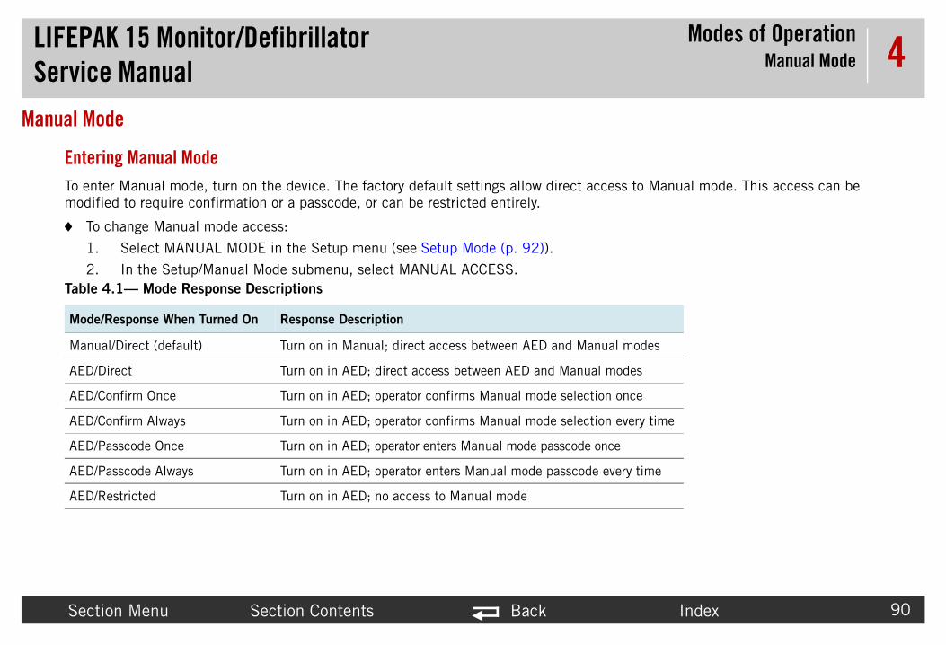
LIFEPAService
Modes of OperationManual Mode
Secti Index 90
4Manual Mo
EnterTo ent cess to Manual mode. This access can be modifi
To
1.
2.Table
Mode/
Manua ual modes
AED/D modes
AED/C n once
AED/C n every time
AED/P nce
AED/P every time
AED/R
K 15 Monitor/Defibrillator Manual
on Menu Section Contents Back
de
ing Manual Modeer Manual mode, turn on the device. The factory default settings allow direct aced to require confirmation or a passcode, or can be restricted entirely.
change Manual mode access:
Select MANUAL MODE in the Setup menu (see Setup Mode (p. 92)).
In the Setup/Manual Mode submenu, select MANUAL ACCESS. 4.1— Mode Response Descriptions
Response When Turned On Response Description
l/Direct (default) Turn on in Manual; direct access between AED and Man
irect Turn on in AED; direct access between AED and Manual
onfirm Once Turn on in AED; operator confirms Manual mode selectio
onfirm Always Turn on in AED; operator confirms Manual mode selectio
asscode Once Turn on in AED; operator enters Manual mode passcode o
asscode Always Turn on in AED; operator enters Manual mode passcode
estricted Turn on in AED; no access to Manual mode

LIFEPAService
Modes of OperationAED Mode
Secti Index 91
4AED Mode
AboutFactor evice to operate in AED (automated external defibri erent menus. The Setup/AED Mode menu allows
To
1.
2.
3.
4.
5.
6.
7.
8.
K 15 Monitor/Defibrillator Manual
on Menu Section Contents Back
AED Mode and Entering AED Modey default settings allow the device to operate in Manual mode. If you want the dllator) mode when it is turned on, you must change several setup options in diff you to change settings for the AED prompted protocol.
set up the device to turn on in AED mode:
Select MANUAL MODE in the Setup menu (see Setup Mode (p. 92)).
In the Setup/Manual Mode submenu, select MANUAL ACCESS.
Select the desired AED/XXX option.
Press HOME SCREEN.
Select MONITORING and then select CHANNELS.
Select SET 1 and then select CHANNEL 1.
Select PADDLES.
Select PREVIOUS PAGE. Confirm that Set 1 appears as the Default Set.

LIFEPAService
Modes of OperationSetup Mode
Secti Index 92
4Setup Mod
AboutSetup gs based on local medical protocols and specif ing characteristics, alarms setup, transm ption that resets the device to the factory defaul which remain unchanged). When setup is compl n, the operating defaults you selected are active.
PresePrint t e menu or store setup options using the LIFEP ervice.
NOTE ndows®-based application designed to assist ou can download the tool from Physio-
K 15 Monitor/Defibrillator Manual
on Menu Section Contents Back
e
Setup Modemode allows you to change the factory default settings and define custom settinic needs. Options include general characteristics, manual and AED mode operatission sites, time-of-day clock, and other options. There is also a factory reset ot settings, (except for transmission menu entries and the maintenance interval, ete, turn off the device to save the settings. The next time the device is turned o
rving the Existing Setup Optionshe existing device setup options by selecting Print Defaults from the Setup modAK Defibrillator Software Solutions Configuration Setup Tool before performing s
: The LIFEPAK Defibrillator Software Solutions Configuration Setup Tool is a Wiyou in managing the setup options in your LIFEPAK 15 monitor/defibrillator. YControl.com.

LIFEPAService
Modes of OperationSetup Mode
Secti Index 93
4Enter To
1.
2.
3.
For moMonitofor V2
ral...al Mode...ode...etronome...
g...oring...ad...s...
Alarms...Printer...Transmission...Clock...Reset Defaults...Print DefaultsSet Passcodes...Service...
Setup
Enter Setup Mode passcode
Setup
K 15 Monitor/Defibrillator Manual
on Menu Section Contents Back
ing Setup Modeenter the Setup mode:
Press and hold OPTIONS and EVENT, and then turn the device ON. Continue holding until the Setup mode passcode prompt appears. The factory default passcode is 0000; the reserved technician passcode is 5433.
To enter the passcode, rotate the SPEED DIAL to select a digit, and then press the SPEED DIAL to continue. After the last digit is entered, the Setup menu appears.
Rotate the SPEED DIAL to select a setup option, and then press the SPEED DIAL to display the option submenu.
re detailed information about Setup mode options, see LIFEPAK 15 r/Defibrillator Setup Options (MIN 3208011 for V1, or 3206226
).GeneManuAED MCPR MPacinMonit12-LeEvent

LIFEPAService
Modes of OperationService Mode
Secti Index 94
4Service Mo
AboutServic
• Pe
• Pe
• Vie
• Se• Se
K 15 Monitor/Defibrillator Manual
on Menu Section Contents Back
de
Service Modee mode functions allow qualified service personnel to:
rform device calibration routines:~ Defibrillation calibration~ Pacing calibration~ Printer calibration~ CO2 calibration~ NIBP calibration~ Temperature calibration
rform device tests:~ Buttons test~ Pixels test~ Printer test~ Voice/Tone test
w the device status registers:~ Device Log status~ Service Log status~ Device Data status~ Counters status~ Clear Memory (clears data management memory)
t the Service mode passcodet the maintenance prompt interval

LIFEPAService
Modes of OperationService Mode
Secti Index 95
4Enter To
1.
2.
3.
4.
Calibr
Tests Status
Set Pa
Maint
Setup
K 15 Monitor/Defibrillator Manual
on Menu Section Contents Back
ing Service Modeenter the Service mode:
Enter the Setup Mode (see Setup Mode (p. 92))
Rotate the SPEED DIAL to select SERVICE in the Setup menu, and then press the SPEED DIAL. The Service mode passcode prompt appears. The factory default passcode is 0000; the reserved technician passcode is 5433.
To enter the passcode, rotate the SPEED DIAL to select a digit, and then press the SPEED DIAL to continue. After the last digit is entered, the Service menu appears.
Rotate the SPEED DIAL to select a service option, and then press the SPEED DIAL to display the option overlay.
ation — See Test and Calibration Procedures.— See Performance Inspection Procedures. — See Troubleshooting (p. 98).sscode — Set a Service mode access passcode.Prompt — See Preventive Maintenance (p. 145). — Return to the Setup Home Screen.

LIFEPAService
Modes of OperationDemo Mode
Secti Index 96
4Demo Mod
AboutDemo EPAK 15 monitor/defibrillator, including:
• EC• Sp• Sp• Sp• CO• NIB• IP• Tem• Tre• Ala• Eve
Enter To
1. ot enter Demo mode if any front panel cable is
2. Demo mode screen appears.
3.
K 15 Monitor/Defibrillator Manual
on Menu Section Contents Back
e
Demo Modemode allows you to practice or demonstrate the monitoring functions of the LIF
G lead selectionO2COMet2P
peraturend graphsrmsnts
ing Demo Modeenter Demo mode:
Remove all front panel cables from the device (therapy, ECG, etc.). You cannattached.
Press and hold EVENT and HOME SCREEN, and then turn on the device. The
To exit Demo mode, turn the device off.

LIFEPAService
Modes of OperationArchive Mode
Secti Index 97
4Archive Mo
AboutPatien monitoring ends and the current Patient Record
To
1.
2.
3.
K 15 Monitor/Defibrillator Manual
on Menu Section Contents Back
de
Archive Mode and Entering Archive Modet information is stored in Archive mode. When you enter Archive mode, patient is saved and closed.
enter Archive mode:
Turn on the device and press OPTIONS.
Select ARCHIVES, and then select YES.
NOTE: You may be required to enter a password to enter Archive mode.
Turn the device OFF to exit Archive mode.

Index
LIFEPAServic
TroubleshootingContents
98
5TroubleThis section eparate troubleshooting chart keyed to the Performance equire operator interpretation. Choose from the following top
• Tr• U• D• D• S• P• C• C• S• U• U• D• S• P• E• P• Th• P• P• S• C• S• D
Section Menu Back
K 15 Monitor/Defibrillatore Manualshooting describes error code usage, interpretation, and corrective action. It includes a s Inspection Procedures (PIP) section and individual troubleshooting tests that rics:
oubleshooting Chart (p. 99)sing the Service/Status Features (p. 106)evice Log (p. 108)evice Data (p. 110)ervice Log (p. 113)rocessing Service Log Codes (p. 115)ounters (p. 116)lear Memory (p. 118)ervice Log Code Categories (p. 119)tility Service Codes (p. 121)ser Interface Service Codes (p. 122)ata Management Service Codes (p. 124)ystem Monitor Service Codes (p. 125)rocessor Control Service Codes (p. 126)CG Service Codes (p. 128)atient Parameter Service Codes (p. 129)erapy Service Codes (p. 130)
rinter Service Codes (p. 137)ower Management Service Codes (p. 138)erial Communication Service Codes (p. 139)orrective Action Codes (p. 140)ervice LED (p. 143)isplay Pixels Test (p. 144)

LIFEPAService
TroubleshootingTroubleshooting Chart
Secti Index 99
5Troublesho
NOTE ly to correct the observed symptom.ge
Table
Area Action
Physic replace loose items.oken components.
ning Procedure (p. 154).
Control Keypad failure.ypad failure.158).tification Label (162).zard Label (164).
) failure.
Power roperly maintained batteries.en battery pin(s)./Interface PCB cable connection issue.CB failure.
e Log Codes (p. 115) for assistance.
the Maintenance Prompt Interval (p. 150).
K 15 Monitor/Defibrillator Manual
on Menu Section Contents Back
oting Chart : Corrective actions are listed in sequential order according to what is most like
5.1— Corrective Actions
Observed Symptom Suggested Corrective
al Inspection Loose or broken hardware Locate and tighten orLocate and replace br
Evidence of dirt, fluids, or foreign objects
Perform External Clea
Damaged keypad or label Possible A09 Printer Possible A10 Main KeReplace Bezel Label (Replace Product IdenReplace Explosion/Ha
Damaged battery pin(s) Possible battery pin(s
On/Self Test No power ON Install fully charged, pPossible loose or brokPossible W04 SystemPossible A03 Power P
Service LED remains ON See Processing Servic
MAINTENANCE DUE message appears
See Setting/Resetting

LIFEPAService
TroubleshootingTroubleshooting Chart
Secti Index 100
5
LCD D s Test (p. 144).embly failure.PCB failure.
Keypa Control Keypad failure.ypad failure.e PCB failure.PCB failure.
Printe rinter paper.
sembly; replace if necessary.
PCB failure.
aper.
sembly; replace if necessary.PCB failure.
nter Calibration at 25 mm.
nter Calibration at 12.5 mm.
r (see Paper Sensor Cleaning (p. 156)). paper is correctly loaded.sembly; replace if necessary.
Table
Area Action
K 15 Monitor/Defibrillator Manual
on Menu Section Contents Back
isplay Improper LCD response Perform Display PixelPossible A11 LCD AssPossible A01 System
ds Test Improper key response Possible A09 Printer Possible A10 Main KePossible A05 InterfacPossible A01 System
r Test Missing dots in printed “X” Verify use of proper pClean the printhead.Check A12 Printer As
One or more horizontal lines missing or distorted
Possible A01 System
Missing or broken characters Verify use of proper pClean the printhead.Check A12 Printer AsPossible A01 System
Improper 25 mm marker spacing Calibrate the TCP–Pri
Improper 12.5 mm marker spacing Calibrate the TCP–Pri
CHECK PRINTER message appears Clean the paper sensoVerify that the printerCheck A12 Printer As
5.1— Corrective Actions (Continued)
Observed Symptom Suggested Corrective

LIFEPAService
TroubleshootingTroubleshooting Chart
Secti Index 101
5
Audio r Assembly failure. e PCB failure.PCB failure.
PowerTest
retry test.x Power adapter LED is ON and input cable is
ttery and retry test.en battery pin(s).CB failure.
QUIK-Hard PEnerg
etry test.e Log Codes (p. 115) for assistance.r hard paddles; replace if necessary.
y Connector Cable failure. PCB failure.c Module PCB failure.e Resistor failure.
Storage Capacitor failure.
Relay connection problem at P22. Relay failure. PCB failure.
ator Energy Calibration.
Table
Area Action
K 15 Monitor/Defibrillator Manual
on Menu Section Contents Back
Test Inaudible or garbled audio Possible W17 SpeakePossible A05 InterfacPossible A01 System
Source Management Verify instructions and(if available) Verify Auconnected to device.Substitute another baPossible loose or brokPossible A03 Power P
COMBO or addles Delivered
y Test
No energy discharge Verify test setup and rSee Processing ServicCheck therapy cable oPossible W11 TherapPossible A04 TherapyPossible A22 BiphasiPossible A14 InductivPossible A15 Energy
ABNORMAL ENERGY DELIVERY message appears
Possible A13 TransferPossible A13 TransferPossible A04 Therapy
Delivered energy out of tolerance Perform TCP–Defibrill
5.1— Corrective Actions (Continued)
Observed Symptom Suggested Corrective

LIFEPAService
TroubleshootingTroubleshooting Chart
Secti Index 102
5
QUIK-Imped
etry test.replace if necessary.y Connector Cable failure. PCB failure.
DefibrTest
etry test.ernal high-voltage wiring.-voltage wire connection issue.
QUIK-PaddlCardio
etry test.
PCB failure.
c and attempt to discharge.ypad failure.
or hard paddles; replace if necessary.
etry test.PCB failure.
Pacing etry test. Relay connection problem at P22. Relay failure. PCB failure.
User T e Log Codes (p. 115) for assistance.
Table
Area Action
K 15 Monitor/Defibrillator Manual
on Menu Section Contents Back
COMBO Patient ance Test
Inappropriate screen message response Verify test setup and rCheck therapy cable; Possible W11 TherapPossible A04 Therapy
illation Isolation Measured energy exceeds 2 joules Verify test setup and rPossible damaged intPossible internal high
COMBO or Hard es Synchronous version Test
No Sync mark Verify test setup and rAdjust ECG size.Possible A01 System
Failure to transfer coincident with Sync mark
Take device out of SynPossible A10 Main KeCheck therapy cables
Sync discharge time exceeds 60 ms Verify test setup and rPossible A01 System
Test No pacer output Verify test setup and rPossible A13 TransferPossible A13 TransferPossible A04 Therapy
est Service LED illuminates, User Test fails See Processing Servic
5.1— Corrective Actions (Continued)
Observed Symptom Suggested Corrective

LIFEPAService
TroubleshootingTroubleshooting Chart
Secti Index 103
5
12-Le etry test.lace if necessary.nnector Cable failure.PCB failure.
etry test.lace if necessary.PCB failure.
3-Lea5-Wire
etry test.lace if necessary.nnector Cable failure.PCB failure.
etry test.lace if necessary.PCB failure.
QUIK-Tests
etry test.replace if necessary. PCB failure.PCB failure.
etry test.replace if necessary. PCB failure.
Table
Area Action
K 15 Monitor/Defibrillator Manual
on Menu Section Contents Back
ad ECG Tests Inappropriate screen message response Verify test setup and rCheck ECG cable; repPossible W07 ECG CoPossible A01 System
ECG gain out of tolerance Verify test setup and rCheck ECG cable; repPossible A01 System
d ECG Tests ECG Tests
Inappropriate screen message response Verify test setup and rCheck ECG cable; repPossible W07 ECG CoPossible A01 System
ECG gain out of tolerance Verify test setup and rCheck ECG cable; repPossible A01 System
COMBO ECG ECG gain out of tolerance Verify test setup and rCheck therapy cable; Possible A04 TherapyPossible A01 System
ECG fast restore out of tolerance Verify test setup and rCheck therapy cable; Possible A04 Therapy
5.1— Corrective Actions (Continued)
Observed Symptom Suggested Corrective

LIFEPAService
TroubleshootingTroubleshooting Chart
Secti Index 104
5
SpO2/ etry test.r test subject.eplace if necessary.uration setup error.odule failure.onnector Cable failure.B failure.
n Table 5.12 on page 129 for assistance.
NIBP test.ink in tubing between NIBP connector and NIBP
odule failure.
in Table 5.12 on page 129 for assistance.
Tempe n required; verify test setup and test equipment s.adapter cable failure.PCB failure.
Table
Area Action
K 15 Monitor/Defibrillator Manual
on Menu Section Contents Back
SpCO/SpMet Features Saturation reading missing or out of tolerance.
SpO2 displays XXX in the SpO2 region of the display with the Service LED OFF (review diagnostic log).
Verify test setup and rRetry test with anotheCheck finger sensor; rPossible device configPossible A16 SpO2 MPossible W22 SpO2 CPossible A06 OEM PC
SpO2 displays XXX in the SpO2 region of the display with the Service LED ON
See error code 900e i
Feature NIBP displays XXX in the NIBP region of the display with the Service LED OFF (review diagnostic log).
Perform NIBP leakagePossible blockage or kmodule. Possible A21 NIBP m
NIBP displays XXX in the NIBP region of the display with the Service LED ON
See error code 9119
rature Feature TEMP: ACCURACY OUTSIDE LIMITS message is displayed, and the temperature value is “XXX”
Temperature calibratioaccuracy requirementPossible temperature Possible A01 System
5.1— Corrective Actions (Continued)
Observed Symptom Suggested Corrective

LIFEPAService
TroubleshootingTroubleshooting Chart
Secti Index 105
5
CO2 FNote:take uinterncompl
etry test.alibration gas canister is empty.e if it is disconnected.se inside device. dule failure.
kinking of input tubing between CO2 connector and CO2
dule failure.
kinking of tubing inside device. dule failure.
5 in Table 5.12 on page 129.
onnector with compressed air to remove loose debris.
Table
Area Action
K 15 Monitor/Defibrillator Manual
on Menu Section Contents Back
eature The CO2 module can p to 6 minutes for all al processes to ete.
CO2 fails calibration Verify test setup and rCheck to see if CO2 cCheck FilterLine to seCheck for pinched hoPossible A23 CO2 mo
CO2 displays FilterLine Blockage message
Replace FilterLine.Possible occlusion or module.Possible A23 CO2 mo
CO2 displays XXX in the CO2 region of the display with Service LED OFF
Replace FilterLine.Possible occlusion or Possible A23 CO2 mo
CO2 displays XXX in the CO2 region with Service LED ON (review diagnostic log).
Review error code 920
CO2 FilterLine installed with no indication on display that CO2 is connected
Clean the CO2 input cReplace FilterLine.
5.1— Corrective Actions (Continued)
Observed Symptom Suggested Corrective

LIFEPAService
TroubleshootingUsing the Service/Status Features
Secti Index 106
5Using the S
IntrodThe de ta such as stored manufacturing data, record
Displa To
1.
2.
3.
K 15 Monitor/Defibrillator Manual
on Menu Section Contents Back
ervice/Status Features
uctionvice includes a series of service/status screens and menus that detail device daed errors, and counters for shock and pacing operation.
ying the Service/Status Submenudisplay the Service/Status submenu:
Press and hold the OPTIONS and EVENT buttons, and then turn the device ON. Continue holding until the Setup mode passcode prompt appears.
Enter the passcode 5433 by rotating the SPEED DIAL to select a digit, and then pressing the SPEED DIAL to continue. After the last digit is entered, the Setup menu appears.
Rotate the SPEED DIAL to select SERVICE in the Setup menu, and then press the SPEED DIAL. At the service passcode prompt, enter the passcode 5433. The Service menu appears.

LIFEPAService
TroubleshootingUsing the Service/Status Features
Secti Index 107
54.
K 15 Monitor/Defibrillator Manual
on Menu Section Contents Back
Rotate the SPEED DIAL to select STATUS, and then press the SPEED DIAL to display the Service/Status submenu.

LIFEPAService
TroubleshootingDevice Log
Secti Index 108
5Device Log
IntrodThe De
Displa To
1.
K 15 Monitor/Defibrillator Manual
on Menu Section Contents Back
uctionvice Log displays accumulative device operations, such as the shock count.
ying the Device Logdisplay the Device Log:
Display the Service/Status submenu (Displaying the Service/Status Submenu (p. 106)), and then select DEVICE LOG.

LIFEPAService
TroubleshootingDevice Log
Secti Index 109
5DevicThe De
Table
Data
Fault stored in
Power
Pacing
Shock
Power
Printe
SpO2
CO2 O
NIBP
K 15 Monitor/Defibrillator Manual
on Menu Section Contents Back
e Log Entriesvice Log includes the data listed in Table 5.2.
5.2—Device Log Entries
Description
Messages Records YES or NO to indicate whether there are any error codes the Service Log (see Processing Service Log Codes (p. 115))
Cycle Count Number of times the device has been turned on
Count Total pacing pulses delivered by the device
Count Total times the device defibrillation capacitor has been charged
On Time Total device power-on time
r On Time Total printer running time
Operating Time Total SpO2 running time
perating Time Total CO2 running time
Inflation Cycles Total number of inflation cycles

LIFEPAService
TroubleshootingDevice Data
Secti Index 110
5Device Dat
IntrodDevice art numbers.
Displa To
1.
K 15 Monitor/Defibrillator Manual
on Menu Section Contents Back
a
uction Data displays essential device characteristics, such as the serial number and p
ying the Device Datadisplay Device Data:
Display the Service/Status submenu (Displaying the Service/Status Submenu (p. 106)), and then select DEVICE DATA.

LIFEPAService
TroubleshootingDevice Data
Secti Index 111
5DevicThe de
Table
Data
Serial s lost
Manuf perating
Displa
Audio
FPGA
System part ith each
Power
SBC P
SpO2
SpO2
CO2 V
K 15 Monitor/Defibrillator Manual
on Menu Section Contents Back
e Data Entriesvice data includes item listed in Table 5.3.
5.3—Device Data Entry
Description
Number Device serial number. If the serial number is blank, the device haimportant configuration data.
acture Date Date when the device was manufactured, specifically, when the osoftware was loaded
y String P/N Font software part number and version, language dependent
P/N Audio software part number and version, language dependent
Version Field-Programmable Gate Array software version
SW P/N Current version of the device operating software. The seven-digit number is fixed, while the three-digit extension number changes wsoftware version
SW P/N Power assembly software part number and version
/N Single-Board Computer hardware part number and version
S/N SpO2 hardware serial number
Version SpO2 software version numbers
ersion CO2 software version number and serial number

LIFEPAService
TroubleshootingDevice Data
Secti Index 112
5
NIBP
Blueto
Table
Data
K 15 Monitor/Defibrillator Manual
on Menu Section Contents Back
Version NIBP software version number
oth Version Bluetooth software version number and date stamp
5.3—Device Data Entry (Continued)
Description

LIFEPAService
TroubleshootingService Log
Secti Index 113
5Service Lo
IntrodThe de or device malfunction by using a system of error c our-digit hexadecimal error code is written into th 3) illuminates. The illuminated Service LED is your ing Service Log Codes (p. 115)).
Errors cian before the device is placed back into active g and clearing any error code(s).
Error c rror codes can indicate transient electro nsient EMI or ESD as the source of an error, clear t t down and restart the device. If the error code d
K 15 Monitor/Defibrillator Manual
on Menu Section Contents Back
g
uctionvice operating software is designed to detect and report any improper operationodes. When an internal program or process fails to execute properly, a specific fe device Service Log (for example, 500e), and the front panel Service LED (p. 14 signal to examine the Service Log and process any reported errors (see Process
rarely occur and should be investigated thoroughly by a qualified service techniuse. Always complete the Performance Inspection Procedures after encounterin
odes stored in the Service Log may not necessarily indicate a permanent error. Emagnetic interference (EMI) or electrostatic discharge (ESD). If you suspect trahe error code(s) as described in Clearing the Service Log (p. 114), and then shuoes not recur, it may have been the result of EMI or ESD.

LIFEPAService
TroubleshootingService Log
Secti Index 114
5Displa To
1.
2.
Clear To
1.
2.
3.
K 15 Monitor/Defibrillator Manual
on Menu Section Contents Back
ying the Service Logdisplay the Service Log:
Display the Service/Status submenu (Displaying the Service/Status Submenu (p. 106)).
Select SERVICE LOG. The Service/Status/Service Log overlay displays errors by date, time, error, and error extension.
ing the Service Logclear the Service Log:
Display the Service/Status submenu (Displaying the Service/Status Submenu (p. 106)), and then select SERVICE LOG.
Using the SPEED DIAL, select CLEAR LOG on the Service/Status/Service Log overlay.
NOTE: The CLEAR LOG action will record the error(s) on the 100-mm printer.
Turn the device OFF or navigate to other service topics, as required.

LIFEPAService
TroubleshootingProcessing Service Log Codes
Secti Index 115
5Processing
When into the device Service Log (p. 113) (for examp es.
To
1.
2. evice OFF. The CLEAR LOG action will record the
3.
use. The error code(s) may have been related
nd compare your PIP failure with the
4.
ation.ur specific error code in the table.ponding corrective action. formance Inspection Procedures (PIP).
5. sales representative.
K 15 Monitor/Defibrillator Manual
on Menu Section Contents Back
Service Log Codesan internal program or process fails to execute properly, an error code is written le, 500e), and the front panel Service LED (see Service LED (p. 143)) illuminat
process error codes:
Review the error code(s) by displaying the Service Log (p. 113).
Clear the Service Log (Clearing the Service Log (p. 114)), and then turn the derror(s) on the 100-mm printer.
Complete the Performance Inspection Procedures (PIP).
~ If the PIP completes successfully, the device may be returned to regular to EMI or ESD.
~ If the Service LED illuminates at any time during the PIP, stop the PIP aTroubleshooting Chart (p. 99). Continue with step 4.
Locate the specific corrective action for a Service Log error code as follows:
a. Display the Service Log to view the error code(s).b. Review the Service Log Code Categories (p. 119) for general informc. Click the appropriate link in the Initial Digit column and locate yod. Click the link(s) in the Corrective Action column to view the correse. Service the device based on these inputs, and then repeat the Per
For persistent Service Log codes, contact your local Physio-Control service or

LIFEPAService
TroubleshootingCounters
Secti Index 116
5Counters
IntrodThe de ing-total counts.
Displa To
1.
K 15 Monitor/Defibrillator Manual
on Menu Section Contents Back
uctionvice counters display the number of shocks delivered in both subtotal and runn
ying the Countersdisplay the counters:
Display the Service/Status submenu (Displaying the Service/Status Submenu (p. 106)), and then select COUNTERS.

LIFEPAService
TroubleshootingCounters
Secti Index 117
5UnderThe Se
ResetSelect rs in the boxes, but not the running-total counte
Table
Data
Total S ounter
360 J delivered tal of all
225 - -joule mn is a y the
1 - 20 le shocks running (cannot
K 15 Monitor/Defibrillator Manual
on Menu Section Contents Back
standing the Countersrvice/Status/Counters overlay displays the counters shown in Table 5.4.
ting the Counters CLEAR ALL on the Service/Status/Counters overlay to reset the subtotal counters.
5.4—Counters
Description
hocks Running total of all the shocks ever delivered by the device. This ccannot be reset.
Shocks The number in the box represents the number of 360-joule shocks since the last reset. The number in the right column is a running to360-joules shocks ever delivered by the device (cannot be reset).
325 J Shocks The number in the box represents the number of 225-joule to 325shocks delivered since the last reset. The number in the right colurunning total of all 225-joule to 325-joule shocks ever delivered bdevice (cannot be reset).
0 J Shocks The number in the box represents the number of 0-joule to 200-joudelivered since the last reset. The number in the right column is atotal of all 0-joule to 200-joule shocks ever delivered by the devicebe reset).

LIFEPAService
TroubleshootingClear Memory
Secti Index 118
5Clear Mem
IntrodThe Cl e A01 System PCB. Specifically, you clear:
• EC us ECG waveforms) is permanently deleted.• PaNorma r different use and the previous patient data is no l ervice actions.
NOTE transmit the data to a receiving device or tructions).
Clear To
1. tatus Submenu (p. 106), and then select CLEAR
2. nominal 30 seconds.
K 15 Monitor/Defibrillator Manual
on Menu Section Contents Back
ory
uctionear Memory feature is used to clear the FLASH data management memory on th
G Data – All stored ECG data (up to 360 minutes of First-In-First-Out continuotient Reports – All stored patient reports are permanently deleted.
lly you clear the data management memory after the device is placed into new oonger required. You also clear the data management memory as part of certain s
: To save important patient data before clearing the data management memory,print out individual patient data (see “Data Management” in the operating ins
ing the Data Management Memoryclear the data management memory (this is permanent; there is no undo):
Display the Service/Status submenu as described in Displaying the Service/SMEMORY.
A countdown timer appears to indicate the clearing process, which requires a

LIFEPAService
TroubleshootingService Log Code Categories
Secti Index 119
5Service LoService log co mal format.
Table
Initial d Assemblies
0xxx
1xxx herapy, A05 Interface, A09 Printer Control Keypad,
3xxx
4xxx herapy
5xxx
6xxx
9xxx EM PCB, A16 SpO2 Module, A23 CO2 Module
axxx ower, A04 Therapy, A15 Energy Storage Capacitor,
bxxx rinter Assembly
K 15 Monitor/Defibrillator Manual
on Menu Section Contents Back
g Code Categoriesdes are organized into the categories shown in Table 5.5, in four-digit hexadeci
5.5—Error Code Categories
Digit Category Detail Table Associated PCBs an
UT Utility Service Codes (p. 121) A01 System
UI User Interface Service Codes (p. 122) A01 System, A04 TA10 Main Keypad
DM Data Management Service Codes (p. 124)
A01 System
SM System Monitor Service Codes (p. 125)
A01 System, A04 T
PC Processor Control Service Codes (p. 126)
A01 System
ECG ECG Service Codes (p. 128) A01 System
PPxx Patient Parameter Service Codes (p. 129)
A01 System, A06 OA21 NIBP Module,
TH, DE, PA Therapy Service Codes (p. 130) A01 System, A03 PA22 Biphasic PCB
PR Printer Service Codes (p. 137) A01 System, A12 P

LIFEPAService
TroubleshootingService Log Code Categories
Secti Index 120
5
cxxx ower
dxxx
Table
K 15 Monitor/Defibrillator Manual
on Menu Section Contents Back
PM Power Management Service Codes (p. 138)
A01 System, A03 P
SC Serial Communication Service Codes (p. 139)
A01 System
5.5—Error Code Categories (Continued)

LIFEPAService
TroubleshootingUtility Service Codes
Secti Index 121
5Utility Serv
Table
CodeCorrective
Action Code
0002 1
0003 1
0004 ror information. Flash not updated.) 1
0005 error information. Flash not updated.) 1
0006 error information. Flash not updated.) 1
0008 1
000a 1
000c re to read the register after three tries. May 1
000d DC Self-Test Calibration test failure.) 1
000e sh.) 1
000f lash.) 1
K 15 Monitor/Defibrillator Manual
on Menu Section Contents Back
ice Codes
5.6—Initial Digit 0, Utility Service Codes (UT)
Service Code Description
UT_ERROR_FLASH_VPP (Error during flash block erase. Valid for all flash sizes.)
UT_ERROR_FLASH_ERASE (Flash memory block erase failure. Valid for all flash sizes.)
UT_ERROR_FLASH_8BIT_WRITE (Error during 8-bit flash write. Error status bits indicate er
UT_ERROR_FLASH_16BIT_WRITE (Error during 16-bit flash write. Error status bits indicate
UT_ERROR_FLASH_PAGE_WRITE (Error during 16-bit flash write. Error status bits indicate
UT_ERROR_ADC_READ (Error during ADC read. ADC serial channel not available.)
UT_ERROR_DAC_FAILURE (ECG DAC self-test failed. ECG DAC failure after cold boot.)
UT_ERROR_ADC_TEST_REG (ADC Test Register Failure. ADC Test Register test failure. Failualso be caused by the serial channel not responding.)
UT_ERROR_ADC_CAL_NOT_COMPLETE (ADC busy bit not clear 150 ms after calibration. A
UT_ERROR_VP_FLASH_ID_UNKNOWN (Unknown manufacture/device ID for voice/printer fla
UT_ERROR_DP_FLASH_ID_UNKNOWN (Unknown manufacture/device ID for data/program f

LIFEPAService
TroubleshootingUser Interface Service Codes
Secti Index 122
5User Interf
Table
CodeCorrective
Action Code
1005 expected CRC; lower 16 bits contain the 1
1006 mode.) 28, 10, 6, 1
1007 ware saw a key closure of this key.) 11, 1
1008 software saw a key closure of this key.) 11, 1
100a saw a key closure of this key.) 11, 1
100b software saw a key closure of this key.) 11, 1
100c the software saw a key closure of this key.) 11, 1
100d are saw a key closure of this key.) 11, 1
100e oftware saw a key closure of this key.) 11, 1
100f re saw a key closure of this key.) 11, 1
1010 re saw a key closure of this key.) 11, 1
1037 in current hardware configuration.) 11, 1
K 15 Monitor/Defibrillator Manual
on Menu Section Contents Back
ace Service Codes
5.7—Initial Digit 1, User Interface Service Codes (UI)
Service Code Description
UI_ERROR_DISPLAY_SELF_TEST (Self-test failed. Upper 16 bits of status code contain theactual CRC.)
UI_ERROR_ENERGY_FAULT (Defib charge out of 15% tolerance. Occurs only during manual
UI_ERROR_12LEAD_KEY_SEEN (This unit is not configured to support 12-lead, but the soft
UI_ERROR_ANALYZE_KEY_SEEN (This unit is not configured to support AED mode, but the
UI_ERROR_NIBP_KEY_SEEN (This unit is not configured to support NIBP, but the software
UI_ERROR_CURRENTUP_KEY_SEEN (This unit is not configured to support pacing, but the
UI_ERROR_CURRENTDOWN_KEY_SEEN (This unit is not configured to support pacing, but
UI_ERROR_RATEUP_KEY_SEEN (This unit is not configured to support pacing, but the softw
UI_ERROR_RATEDOWN_KEY_SEEN (This unit is not configured to support pacing, but the s
UI_ERROR_PACER_KEY_SEEN (This unit is not configured to support pacing, but the softwa
UI_ERROR_PAUSE_KEY_SEEN (This unit is not configured to support pacing, but the softwa
UI_ERROR_UNCONFIGURED_BUTTON (Button test detected key that should not be present

LIFEPAService
TroubleshootingUser Interface Service Codes
Secti Index 123
5
1038 are saw a key closure of this key.) 11, 1
103b 28, 1
1fff 9
Table
CodeCorrective
Action Code
K 15 Monitor/Defibrillator Manual
on Menu Section Contents Back
UI_ERROR_CPR_KEY_SEEN (This unit is not configured to support AED mode, but the softw
UI_ERROR_MISSING_LANGUAGE (Configured language was not available.)
UI_ERROR_EXTRA_INFORMATION (Extra error code information for an above error.)
5.7—Initial Digit 1, User Interface Service Codes (UI) (Continued)
Service Code Description

LIFEPAService
TroubleshootingData Management Service Codes
Secti Index 124
5Data Mana
Table
CodeCorrective
Action Code
3005 disables flash.) 31, 1
3006 quested.) 31, 1
3007 param = block.) 31, 1
3008 k # of failure.) 31, 1
3fff 28, 31, 1
K 15 Monitor/Defibrillator Manual
on Menu Section Contents Back
gement Service Codes
5.8—Initial Digit 3, Data Management Service Codes (DM)
Service Code Description
DM_ERROR_DATABASE_ERASE_ADJUST (Not able to write new lines for new oldest record;
DM_ERROR_DATABASE_ERASE_FAILED (Erase block failed; disables flash; param = block re
DM_ERROR_DATABASE_ERASE_VERIFY (Verification of erased block failed; disabled flash;
DM_ERROR_DATABASE_FLASH_ERASE (Erase database failed; disables flash; param = bloc
DM_ERROR_EXTRA_INFORMATION (Extra error code information for an above error.)

LIFEPAService
TroubleshootingSystem Monitor Service Codes
Secti Index 125
5System Mo
Table
CodeCorrective
Action Code
4009 ddress of failure.) 1, 6
400a expected CRC, low 16 bits include 1, 6
400b CRC, low 16 bits include computed CRC).) 1, 6
400c bits contains ADC value, low 8 bits contains 6, 1
400d 8 bits contains ADC value, low 8 bits 6, 1
4010 1, 6
4011 param = time since last boot.) 6, 1
4012 or found after cold boot.) 1, 6
4013 code = top 16 bits are stored CRC, low 16 1, 6
K 15 Monitor/Defibrillator Manual
on Menu Section Contents Back
nitor Service Codes
5.9—Initial Digit 4, System Monitor Service Codes (SM)
Service Code Description
SM_ERROR_RAM_FAILURE (RAM failure during self-test. 16-bit ram test failure; param = a
SM_ERROR_BAD_CRC (CRC in program flash bad. Program test failure; value = high 16 bitscomputed CRC.)
SM_ERROR_CRC_FAILURE (Program contents failed CRC test; value = high 16 bits expected
SM_ERROR_VOLTAGE_LOW (ADC voltage reading low. HW voltage low; status code = high 8 channel #.)
SM_ERROR_VOLTAGE_HIGH (ADC voltage reading high. HW voltage high; status code = highcontains channel #.)
SM_ERROR_SERVICE_LED (Service LED failure. LED expected to be on, but it is not.)
SM_ERROR_DEFIB_SERVICE_SYNC (Failed to synchronize the defib charge after cold boot;
SM_ERROR_FONT_VOICE_CKSUM (Invalid checksum in font/voice. Font/voice checksum err
SM_ERROR_FONT_VOICE_CRC (Invalid CRC in font/voice flash. Font/voice CRC error; statusbits are computed CRC.)

LIFEPAService
TroubleshootingProcessor Control Service Codes
Secti Index 126
5Processor
Table
CodeCorrective
Action Code
5002 re; param: 0=None, 1=short, 2=long, 1
5003 ; param: 0=None, 1=short, 2=long, 1
5004 onds since last set. Low 16 bits = watchdog 1
5005 1
5006 1
500d .) 1
500e 2, 1
5011 2, 1
5012 2, 1
5013 2, 1
5014 1
5015 1
K 15 Monitor/Defibrillator Manual
on Menu Section Contents Back
Control Service Codes
5.10—Initial Digit 5, Processor Control Service Codes (PC)
Service Code Description
PC_ERROR_WATCHDOG_SHORT_FAILURE (Main watchdog short test failure. Watchdog failu3=power.)
PC_ERROR_WATCHDOG_LONG_FAILURE (Main watchdog long test failure. Watchdog failure3=power.)
PC_ERROR_WATCHDOG_UNEXPECTED (Unexpected main watchdog reset. Top 16 bits = secstatus.)
PC_ERROR_RAM_AT_BOOT (RAM error detected during boot; param = Ram Addr of error.)
PC_ERROR_BAD_CHECKSUM (Program contents failed Checksum test.)
PC_ERROR_CONFIG_VERSION (System configuration version mismatch; param = value read
PC_ERROR_CONFIG_CRC (NVRAM system configuration CRC bad; param = value read.)
PC_ERROR_METERS_VERSION (System meters version mismatch; param = value read.)
PC_ERROR_METERS_CRC (NVRAM system meters/counters CRC bad; param = value read.)
PC_ERROR_MFG_DATA_VERSION (Manufacturing data version mismatch.)
PC_ERROR_MFG_DATA_CRC (NVRAM manufacturing data CRC bad.)
PC_ERROR_FORCED_RESET_FAILED (Forced watchdog reset failed. Unit failed to reset.)

LIFEPAService
TroubleshootingProcessor Control Service Codes
Secti Index 127
5
5019 2,1
501a 1
5032 2,1
5033 2,1
Table
CodeCorrective
Action Code
K 15 Monitor/Defibrillator Manual
on Menu Section Contents Back
PC_ERROR_RTC_BAD (RTC is not running.)
PC_ERROR_RTC_DRIFT (Processor and RTC time out of sync; param = drift.)
PC_ERROR_RTC_NO_BATTERY (No Coin cell battery for the RTC.)
PC_ERROR_RTC_READ (RTC read is not consistent.)
5.10—Initial Digit 5, Processor Control Service Codes (PC)
Service Code Description

LIFEPAService
TroubleshootingECG Service Codes
Secti Index 128
5ECG Servic
Table
CodeCorrective
Action Code
600c 1
600d reported calibration error.) 20
600e y bad.) 20
K 15 Monitor/Defibrillator Manual
on Menu Section Contents Back
e Codes
5.11—Initial Digit 6, ECG Service Codes (ECG):
Service Code Description
ECG_ERROR_DSP_VOLTAGE (DSP preamp supply voltage out of range.)
ECG_ERROR_PREAMP_CALIBRATION (NVRAM calibration constants out of range. HW unit
ECG_ERROR_NVRAM_FAULT (NVRAM redundant value mismatch detected. NVRAM possibl

LIFEPAService
TroubleshootingPatient Parameter Service Codes
Secti Index 129
5Patient Pa
Table
CodeCorrective
Action Code
900e : 1 = found Masimo but should not, 2 = 8
902d t configured for Nellcor sensor support; 8
9119 SW version.) 8
9205 guration. Unit disabled. Param = config- 8
9304 tion bits both on at the same time.) 8
K 15 Monitor/Defibrillator Manual
on Menu Section Contents Back
rameter Service Codes
5.12—Initial Digit 9, Patient Parameter Service Codes (PP)
Service Code Description
PPSP_ERROR_CONFIG (SpO2 module detected but not in manufacturing configuration; paramunit not found.)
PPSP_ERROR_MNC_CONFIG_B (SpO2 module detected but manufacturing configuration, noparam: 1 = Masimo doesn’t support config B, 2 = Device doesn’t support config B.)
PPNI_ERROR_CONFIG_MISMATCH (Device with NIBP module not configured for it; param =
PPCO_ERROR_WRITING_TO_MODULE (CO2 module detected but not in manufacturing confiinfo.)
PPTI_CONFLICT_IP_TEMPER_ERROR_CONFIG (IP and Temperature manufacturing configura

LIFEPAService
TroubleshootingTherapy Service Codes
Secti Index 130
5Therapy Se
Table
CodeCorrective
Action Code
a002 k between the main and defib processor is rror temporarily, but unit is questionable;
10
a003 nk between the main and pacer processor is 10
a004 .) 10
a005 10
a008 10
a00a 7, 10
a00b 10
a00d 10
a00f 10
a010 selected range, low-16 = pacer actual rate.) 10
a011 = selected current, low-16 is actual 10
K 15 Monitor/Defibrillator Manual
on Menu Section Contents Back
rvice Codes
5.13—Initial Character a, Therapy Service Codes (TH)
Service Code Description
TH_ERROR_DEFIB_LINK_DOWN (Lost contact with defib processor. Serial communications linnot functioning.This unit can no longer administer defib therapy. Cycling power may clear the eparam = last defib message time stamp.)
TH_ERROR_PACER_LINK_DOWN (Lost contact with pacer processor. Serial communications linot functioning.)
TH_ERROR_UNEXPECTED_ENERGY (Unexpected energy in the capacitor. No charge delivered
TH_ERROR_CAP_OVERCHARGED (Over-charged capacitor.)
TH_ERROR_DEFIB_DISABLE (No communication with defib HW.)
TH_ERROR_DE_WRONG_ENG_SELECT (Incorrect energy selected; param = energy index.)
TH_ERROR_SHOCK_NOT_DELIVERED (Shock not delivered.)
TH_ERROR_CHARGING_EXPIRED (Charging time expired.)
TH_ERROR_CAP_OUT_OF_RANGE (Capacitor is out of range. Calibration failure.)
TH_ERROR_PA_RATE_OUT_OF_RANGE (Pacing rate out of tolerance; param: high-16 = pacer
TH_ERROR_PA_CURRENT_OUT_OF_RANGE (Pacing current out of tolerance; param: high-16current.)
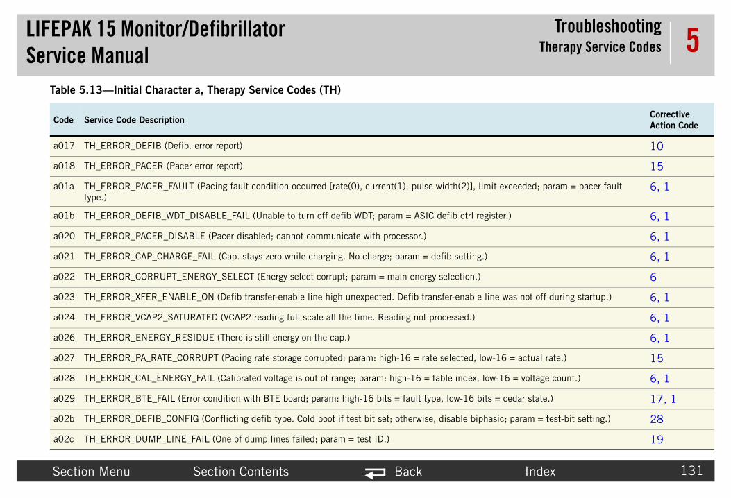
LIFEPAService
TroubleshootingTherapy Service Codes
Secti Index 131
5
a017 10
a018 15
a01a )], limit exceeded; param = pacer-fault 6, 1
a01b trl register.) 6, 1
a020 6, 1
a021 ting.) 6, 1
a022 on.) 6
a023 able line was not off during startup.) 6, 1
a024 d.) 6, 1
a026 6, 1
a027 ed, low-16 = actual rate.) 15
a028 ex, low-16 = voltage count.) 6, 1
a029 6 bits = cedar state.) 17, 1
a02b biphasic; param = test-bit setting.) 28
a02c 19
Table
CodeCorrective
Action Code
K 15 Monitor/Defibrillator Manual
on Menu Section Contents Back
TH_ERROR_DEFIB (Defib. error report)
TH_ERROR_PACER (Pacer error report)
TH_ERROR_PACER_FAULT (Pacing fault condition occurred [rate(0), current(1), pulse width(2type.)
TH_ERROR_DEFIB_WDT_DISABLE_FAIL (Unable to turn off defib WDT; param = ASIC defib c
TH_ERROR_PACER_DISABLE (Pacer disabled; cannot communicate with processor.)
TH_ERROR_CAP_CHARGE_FAIL (Cap. stays zero while charging. No charge; param = defib set
TH_ERROR_CORRUPT_ENERGY_SELECT (Energy select corrupt; param = main energy selecti
TH_ERROR_XFER_ENABLE_ON (Defib transfer-enable line high unexpected. Defib transfer-en
TH_ERROR_VCAP2_SATURATED (VCAP2 reading full scale all the time. Reading not processe
TH_ERROR_ENERGY_RESIDUE (There is still energy on the cap.)
TH_ERROR_PA_RATE_CORRUPT (Pacing rate storage corrupted; param: high-16 = rate select
TH_ERROR_CAL_ENERGY_FAIL (Calibrated voltage is out of range; param: high-16 = table ind
TH_ERROR_BTE_FAIL (Error condition with BTE board; param: high-16 bits = fault type, low-1
TH_ERROR_DEFIB_CONFIG (Conflicting defib type. Cold boot if test bit set; otherwise, disable
TH_ERROR_DUMP_LINE_FAIL (One of dump lines failed; param = test ID.)
5.13—Initial Character a, Therapy Service Codes (TH)
Service Code Description

LIFEPAService
TroubleshootingTherapy Service Codes
Secti Index 132
5
a02d 28, 11
a02e 28
a101 7, 10
a102 10
a103 10
a104 10
a106 28, 10
a107 10
a109 10
a10b 10
a10c 11, 10
a10d 10
a10e 10
a111 10
a112 10
Table
CodeCorrective
Action Code
K 15 Monitor/Defibrillator Manual
on Menu Section Contents Back
TH_ERROR_WRONG_DEFIB_TYPE (Wrong Defib. type for software.)
TH_ERROR_ADC_READ (ADC read failure when getting cap charge.)
DE_ERROR_LONG_WDT (Long watchdog test failed or watchdog did not reset in time.)
DE_ERROR_SHORT_WDT (Short watchdog test failed.)
DE_ERROR_SCI_RCV (Serial port receiver error.)
DE_ERROR_XFER_KEY (Defib HW error.)
DE_ERROR_ENERGY_OUT_OF_BOUND (VCAP-1 over/under charge.)
DE_ERROR_HP_ENG_SELECT (Cannot determine the rotary setting.)
DE_ERROR_CAL_CRC (Calibration Table CRC error.)
DE_ERROR_CHG_TIME (Takes too long to reach charge.)
DE_ERROR_CHG_ENABLE (CHG_EN1 is stuck high.)
DE_ERROR_DUMP_ENERGY (Defib HW error.)
DE_ERROR_RCV (Defib HW error.)
DE_ERROR_ENERGY_NOT_ZERO (Unexpected energy while biphasic is in high-pot test.)
DE_ERROR_TEST_XFER_ENABLE (Problem with transfer; turn on at main.)
5.13—Initial Character a, Therapy Service Codes (TH)
Service Code Description

LIFEPAService
TroubleshootingTherapy Service Codes
Secti Index 133
5
a113 10
a114 10
a115 10
a116 10
a117 10
a118 10
a119 10
a11a 10
a11d 10
a11e 10
a11f 10
a120 10
a123 10
a124 10
a125 10
Table
CodeCorrective
Action Code
K 15 Monitor/Defibrillator Manual
on Menu Section Contents Back
DE_ERROR_TEST_XFER_ENGAGE (Error reading the transfer engage feedback.)
DE_ERROR_TEST_DUMP_RELAY (Biphasic error.)
DE_ERROR_TEST_ADC (Defib HW error.)
DE_ERROR_TEST_DAC (Defib HW error.)
DE_ERROR_TEST_HARDWARE (Defib HW error.)
DE_ERROR_TEST_RAM (Defib HW error.)
DE_ERROR_TEST_ROM (Defib HW error.)
DE_ERROR_TEST_CPU (Defib HW error.)
DE_ERROR_XFER_TIMEOUT (Defib HW error.)
DE_ERROR_BUTTONS_UP (Defib HW error.)
DE_ERROR_SYNC_INTERRUPT (Defib HW error.)
DE_ERROR_SELF_TEST_INCOMPLETE (Defib HW error.)
DE_ERROR_CAL_RCV_CRC (CRC failed for new calibration data.)
DE_ERROR_CAL_NVM_CRC (Cannot write energy table to EEPROM.)
DE_ERROR_DAC_WRITE (Byte could not be written to the DAC through the SPI interface.)
5.13—Initial Character a, Therapy Service Codes (TH)
Service Code Description

LIFEPAService
TroubleshootingTherapy Service Codes
Secti Index 134
5
a126 10
a127 10
a129 10
a12a 10
a12c 10
a12d 10
a12e 17
a12f 17
a130 17
a131 17
a132 17
a133 17
a201 15
a202 15
a203 g these issues.) 15
Table
CodeCorrective
Action Code
K 15 Monitor/Defibrillator Manual
on Menu Section Contents Back
DE_ERROR_ADC_READ (Cannot read from ADC.)
DE_ERROR_TEST_MODE (Must be idle to switch to test mode.)
DE_ERROR_XFER_CABLE (Defib HW error.)
DE_ERROR_XFER_PADDLE (Defib HW error.)
DE_ERROR_CHG_INHIBIT (Defib HW error.)
DE_ERROR_CHG_ENABLE_FAIL (Charge enable feedback indicates not charging.)
DE_ERROR_BTE_FAULT (Cedar BTE Fault Line State.)
DE_ERROR_BTE_FAULT_CLEARED (Cedar BTE Fault Line State.)
DE_ERROR_BTE_RESET (Defib HW error.)
DE_ERROR_NO_BTE_HW (Biphasic HW not found.)
DE_ERROR_NO_BTE_XFER (Defib HW error.)
DE_ERROR_BTE_CEDAR_DRV_HI (A/D high bit sticky.)
PA_ERROR_LONG_WDT (Long watchdog timer test failed.)
PA_ERROR_SHORT_WDT (Short watchdog timer test failed.)
PA_ERROR_SCI_RCV (SCI received overrun, framing or parity. Unit used near high EMI causin
5.13—Initial Character a, Therapy Service Codes (TH)
Service Code Description

LIFEPAService
TroubleshootingTherapy Service Codes
Secti Index 135
5
a204 15
a208 15
a209 15
a20d 15
a20e 15
a20f 15
a210 15
a211 15
a212 15
a213 15
a214 15
a215 15
a216 15
a217 15
a218 15
Table
CodeCorrective
Action Code
K 15 Monitor/Defibrillator Manual
on Menu Section Contents Back
PA_ERROR_2MS_OVERRUN (2 ms ECG sampling overrun.)
PA_ERROR_MSG_RESYNC (Received message incomplete.)
PA_ERROR_MSG_SIZE (Received msg size error/input buff full.)
PA_ERROR_PACE_OVERRUN (Pacing pulse process overrun. Set current to zero.)
PA_ERROR_PULSE_WIDTH (Pacing pulse too long.)
PA_ERROR_A2D_INT (Internal A/D conversion timeout. Set current to zero.)
PA_ERROR_A2D_EX (External A/D conversion timeout. Current set to zero.)
PA_ERROR_SPI (SPI transfer timeout. Current set to zero.)
PA_ERROR_RAM_TEST (RAM test failed. Reset Pacer Processor.)
PA_ERROR_ROM_TEST (ROM CRC test failed.)
PA_ERROR_CPU_TEST (Stack overrun occurred.)
PA_ERROR_STACK_CHECK (Isolated +5 V ref. out of range.)
PA_ERROR_V_ISO_MON (HV present when not pacing.)
PA_ERROR_V_12V_MON (+12 V voltage out of range.)
PA_ERROR_V_HVIS_SENSE (HV present when not pacing.)
5.13—Initial Character a, Therapy Service Codes (TH)
Service Code Description

LIFEPAService
TroubleshootingTherapy Service Codes
Secti Index 136
5
a219 15
a21a 15
a21b 15
a21c 15
a21d 15
a21e 15
a21f 15
a220 15
a221 15
a222 15
a223 15
a224 15
Table
CodeCorrective
Action Code
K 15 Monitor/Defibrillator Manual
on Menu Section Contents Back
PA_ERROR_V_HVIS (HVIS voltage out of range.)
PA_ERROR_CAL_CURRENT (Current calibration failed.)
PA_ERROR_CAL_Z_300 (Impedance 300 calibration failed.)
PA_ERROR_CAL_CURRENT_CRC (Current cal table corrupt.)
PA_ERROR_CAL_IMPEDANCE_CRC (Impedance cal values corrupt.)
PA_ERROR_CAL_Z_0 (Impedance 0 calibration failed.)
PA_ERROR_PACE_I (Current present when not pacing.)
PA_ERROR_NO_HVIS_SENSE (No HV present when pacing.)
PA_ERROR_EXT_A2D_TEST (External A/D test register reset failed.)
PA_ERROR_NO_CAL_HVIS_SENSE (No HV present before current cal.)
PA_ERROR_NO_Q4_SENSE (No Q4 sense when not pacing [Q4 shorted].)
PA_ERROR_Q4_SENSE (Q4 sense present when pacing [CR25 open].)
5.13—Initial Character a, Therapy Service Codes (TH)
Service Code Description
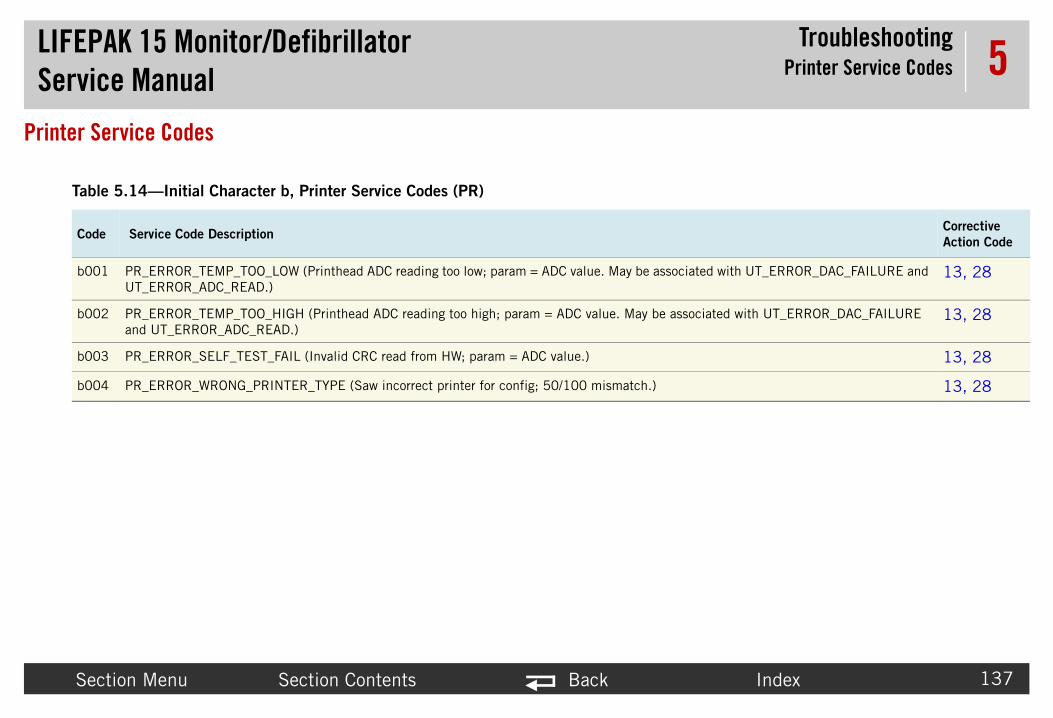
LIFEPAService
TroubleshootingPrinter Service Codes
Secti Index 137
5Printer Ser
Table
CodeCorrective
Action Code
b001 ociated with UT_ERROR_DAC_FAILURE and 13, 28
b002 associated with UT_ERROR_DAC_FAILURE 13, 28
b003 13, 28
b004 13, 28
K 15 Monitor/Defibrillator Manual
on Menu Section Contents Back
vice Codes
5.14—Initial Character b, Printer Service Codes (PR)
Service Code Description
PR_ERROR_TEMP_TOO_LOW (Printhead ADC reading too low; param = ADC value. May be assUT_ERROR_ADC_READ.)
PR_ERROR_TEMP_TOO_HIGH (Printhead ADC reading too high; param = ADC value. May be and UT_ERROR_ADC_READ.)
PR_ERROR_SELF_TEST_FAIL (Invalid CRC read from HW; param = ADC value.)
PR_ERROR_WRONG_PRINTER_TYPE (Saw incorrect printer for config; 50/100 mismatch.)

LIFEPAService
TroubleshootingPower Management Service Codes
Secti Index 138
5Power Man
Table
CodeCorrective
Action Code
c008 7, 1
c009 it detected an external clock failure.) 1, 7
K 15 Monitor/Defibrillator Manual
on Menu Section Contents Back
agement Service Codes
5.15—Initial Character c, Power Management Service Codes (PM)
Service Code Description
PM_ERROR_LOST_COMMS (Lost communications with power PCB.)
PM_ERROR_CLOCK_FAILURE (Power PCB is running on its internal oscillator block because
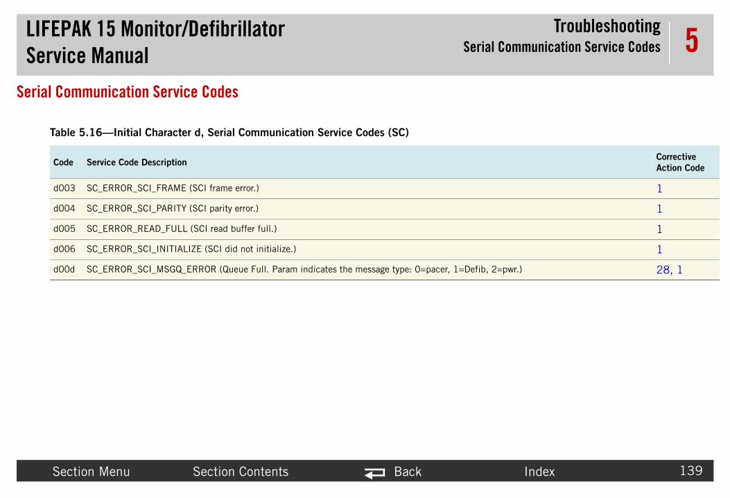
LIFEPAService
TroubleshootingSerial Communication Service Codes
Secti Index 139
5Serial Com
Table
CodeCorrective
Action Code
d003 1
d004 1
d005 1
d006 1
d00d Defib, 2=pwr.) 28, 1
K 15 Monitor/Defibrillator Manual
on Menu Section Contents Back
munication Service Codes
5.16—Initial Character d, Serial Communication Service Codes (SC)
Service Code Description
SC_ERROR_SCI_FRAME (SCI frame error.)
SC_ERROR_SCI_PARITY (SCI parity error.)
SC_ERROR_READ_FULL (SCI read buffer full.)
SC_ERROR_SCI_INITIALIZE (SCI did not initialize.)
SC_ERROR_SCI_MSGQ_ERROR (Queue Full. Param indicates the message type: 0=pacer, 1=

LIFEPAService
TroubleshootingCorrective Action Codes
Secti Index 140
5Corrective
Correc Categories (p. 119). If more than one action is liste
Table
Correc
Action
tional.erformance Inspection Procedures.
.
tional.
tional.
nduct Performance Inspection Procedures.ctional.
K 15 Monitor/Defibrillator Manual
on Menu Section Contents Back
Action Codestive action codes are referenced in the error code tables under Service Log Coded under Description, perform them in the order indicated.
5.17—Corrective Action Codes
tive
CodeDescription
1 System Communications or System Processing Error:a. Verify that the appropriate connecting cables and wire harnesses are funcb. Possible EMI or ESD interference. Clear Service Log and then conduct Pc. Possible A01 System PCB failure.
2 Real time clock failure:Possible nonvolatile RAM failure on coin battery power on A01 System PCB
6 Therapy Processor Error:a. Verify that the appropriate connecting cables and wire harnesses are funcb. Possible A04 Therapy PCB failure.
7 Power Processor Error:a. Verify that the appropriate connecting cables and wire harnesses are funcb. Possible A03 Power PCB failure.
10 Defibrillator out of calibration:a. Complete the TCP–Defibrillator Energy Calibration procedure, and then cob. Verify that the appropriate connecting cables and wire harnesses are func. Possible A04 Therapy PCB failure.d. Possible A22 Biphasic PCB/A14 Inductive Resistor failure.

LIFEPAService
TroubleshootingCorrective Action Codes
Secti Index 141
5
ctional.
uired).
ctional.
rformance Inspection Procedures.ctional.
tional.
tional.
Table
Correc
Action
K 15 Monitor/Defibrillator Manual
on Menu Section Contents Back
11 Configuration or keypad Error:a. Check device configuration settings against installed hardware.b. Possible A09 Printer Control Keypad or A10 Main Keypad failure.c. Verify that the appropriate connecting cables and wire harnesses are fun
8 Device manufacturing configuration bit is not set (Physio-Control service reqPossible nonvolatile RAM failure on A01 System PCB.
13 Printer Error:a. Possible A12 Printer Assembly failure.b. Verify that the appropriate connecting cables and wire harnesses are fun
15 Pacer out of calibration:a. Complete the TCP–Pacer Self-Calibration procedure, and then conduct Peb. Verify that the appropriate connecting cables and wire harnesses are func. Possible A04 Therapy PCB failure.
17 Biphasic fault or unknown energy:a. Verify that the appropriate connecting cables and wire harnesses are funcb. Possible A22 Biphasic PCB failure. c. Possible A04 Therapy PCB failure.
19 Dump error code (a02c):a. Verify that the appropriate connecting cables and wire harnesses are funcb. Possible A04 Therapy PCB failure.c. Possible A22 Biphasic PCB failure.d. Possible A01 System PCB failure.
5.17—Corrective Action Codes (Continued)
tive
CodeDescription

LIFEPAService
TroubleshootingCorrective Action Codes
Secti Index 142
5
tional.
Table
Correc
Action
K 15 Monitor/Defibrillator Manual
on Menu Section Contents Back
20 ECG error:a. Verify that the appropriate connecting cables and wire harnesses are funcb. Possible A01 System PCB failure.
28 The current device software version is recommended, contact Physio-Control Field Service (see Service Information (p. 19)).
31 Clear Data Management memory.
5.17—Corrective Action Codes (Continued)
tive
CodeDescription
LIFEPAService
TroubleshootingService LED
Secti Index 143
5Service LE
What The Se amine such instances using the instructions in Proc
What The Se er it is used to indicate when errors are written on the device, it indicates the presence of errors e LED does not illuminate, it does not indica ice Log and resolve what was written there in the fir
K 15 Monitor/Defibrillator Manual
on Menu Section Contents Back
D
the Service LED Doesrvice LED illuminates when an error code is written to the Service Log. Always exessing Service Log Codes (p. 115).
the Service LED Does Not Dorvice LED is not used to indicate the presence of errors in the Service Log, rath to the Service Log. For example, if the Service LED illuminates when you turn in the Service Log. If you turn the device OFF and then ON again and the Servicte that there are no error codes in the Service Log. You still must review the Servst instance.
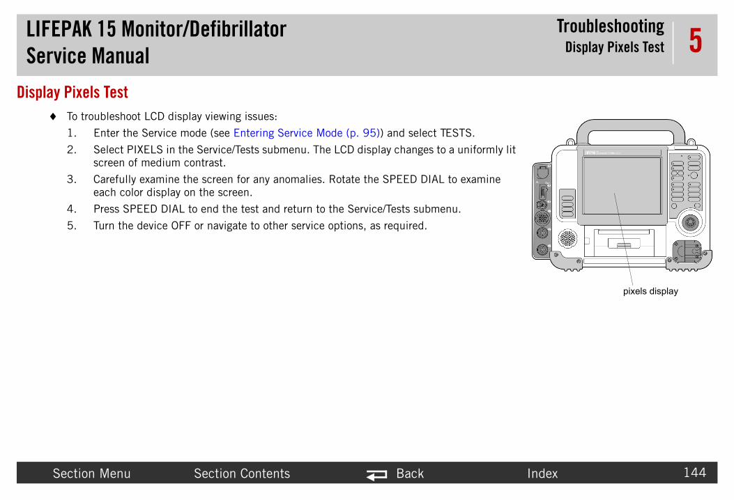
LIFEPAService
TroubleshootingDisplay Pixels Test
Secti Index 144
5Display Pix
To
1. .
2. iformly lit
3. xamine
4.
5.
pixels display
K 15 Monitor/Defibrillator Manual
on Menu Section Contents Back
els Testtroubleshoot LCD display viewing issues:
Enter the Service mode (see Entering Service Mode (p. 95)) and select TESTS
Select PIXELS in the Service/Tests submenu. The LCD display changes to a unscreen of medium contrast.
Carefully examine the screen for any anomalies. Rotate the SPEED DIAL to eeach color display on the screen.
Press SPEED DIAL to end the test and return to the Service/Tests submenu.
Turn the device OFF or navigate to other service options, as required.

Index
LIFEPAServic
Preventive MaintenanceContents
145
6PreventPeriodic ma e electrical and mechanical problems.
For informat Maintenance (p. 158). The information in this section inclu
• D• D• P• S• S• D• S• C• E• A
Section Menu Back
K 15 Monitor/Defibrillatore Manualive Maintenance
intenance, inspection, and testing of the device help prevent and detect possibl
ion about battery charging, conditioning, and battery-related topics, see Batterydes the following:
evice Self Tests (p. 146)evice User Test (p. 147)reventive Maintenance and Testing Schedule (p. 148)cheduled Replacement Items (p. 149)etting/Resetting the Maintenance Prompt Interval (p. 150)evice Useful Life (p. 151)upport Policy (p. 152)leaning (p. 153)nvironmental Conditions (p. 155)12 Printer Maintenance (p. 156)

LIFEPAService
Preventive MaintenanceDevice Self Tests
Secti Index 146
6Device Sel
DevicWhen rrors are detected, the Service LED (p. 143) illumin continuous, repeating over and over again while t
DevicThe de ring the automatic self-test, the defibrillator turns i
• Pe• Sto• Tur
The V2 ement is required to view transmitted auto test da K 15 Monitor/Defibrillator Setup Options guide
If the on on the printed test report.
The au 00 or if batteries are not installed. If the defibri d and the defibrillator turns on normally.
K 15 Monitor/Defibrillator Manual
on Menu Section Contents Back
f Tests
e Self Testyou turn on the LIFEPAK 15 monitor/defibrillator, a series of self-tests occur. If eates. Self-testing does not occur only when the device is turned ON; rather, it ishe device is on.
e Auto Testvice performs an automatic self-test daily at 03:00 (3:00 A.M.), if not in use. Dutself on (ON LED illuminates) briefly and completes the following tasks:
rforms a self-testres the self-test results in the test log and prints reportns itself off
device can also automatically transmit self-test results. LIFENET asset managta. For information about enabling transmission of test results, see the LIFEPAprovided with the V2 device.
defibrillator detects a problem during an auto test, it annotates the fault conditi
tomatic self-test is not performed if the defibrillator is already turned on at 03:llator is manually turned on while a self-test is in progress, the self-test is halte
LIFEPAService
Preventive MaintenanceDevice User Test
Secti Index 147
6Device Use
DevicWhen the next self-test cycle is complete. The user test pe
• Pe• Ch• Sto• Dis
If this he Service Log (p. 113).
K 15 Monitor/Defibrillator Manual
on Menu Section Contents Back
r Test
e User testyou use the SPEED DIAL to navigate to Options/User Test, the device waits until rforms the following tasks:
rforms a self-testarges the defibrillation capacitor to 10 joules, then dumps the chargeres the test results in the test logplays User Test results and prints report
operation does not pass, the Service LED illuminates and an error is written to t

LIFEPAService
Preventive Maintenancee Maintenance and Testing Schedule
Secti Index 148
6PreventiveTable 6.1 sho klist in the operating instructions for additional items). For it ems (p. 149).
Table
Activ onths
Perfo •Test a
PIP–E •Exter •
K 15 Monitor/Defibrillator Manual Preventiv
on Menu Section Contents Back
Maintenance and Testing Schedulews the schedule for preventive maintenance activities (see the Operator’s Checems that should be replaced at regular intervals, see Scheduled Replacement It
6.1—Schedule for Maintenance and Testing
ity Daily As Needed 12 M
rmance Inspection Procedures (PIP) •nd Calibration Procedures (TCP) •xterior Physical Inspection •
nal Cleaning Procedure (p. 154) •

LIFEPAService
Preventive MaintenanceScheduled Replacement Items
Secti Index 149
6ScheduledThe following
• Dis
• EC of this cable.• Lit e.• Co l-time clock.
en coin battery replacement is required.
Table
Table
Repla
Repla
Repla
Repla
K 15 Monitor/Defibrillator Manual
on Menu Section Contents Back
Replacement Items items should be replaced at regular intervals because of their finite life span:
posable Electrodes—Replace electrodes by the “Use by” date.
G cable (3-lead/5-wire/12-lead)—Replace to ensure the continued performancehium-ion battery pak — Replace to ensure maximum operating time of the devicin battery — Replace to ensure the device will not lose battery power for the rea
NOTE: Contact your Physio-Control Service Representative for assistance wh
6.2 shows the schedule for replacement items.
6.2—Replacement Schedule
cement Item Frequency
ce ECG cable 2 years
ce battery pak 2 years
ce coin (clock) battery 5 years

LIFEPAService
Preventive Maintenanceing the Maintenance Prompt Interval
Secti Index 150
6Setting/ReThe MAINTEN months). When this time interval is reached, the message app
After complet lear the MAINTENANCE DUE message and begin the count for
To
1.
2. shows the NEXT PROMPT date for scheduled
3.
4.
To ted:
1. te is revised to the new scheduled maintenance
2.
K 15 Monitor/Defibrillator Manual Setting/Resett
on Menu Section Contents Back
setting the Maintenance Prompt IntervalANCE DUE message can be set up to appear at selected intervals (3, 6, or 12
ears continuously for 10 minutes each time the device is turned on.
ing a scheduled maintenance, reset the maintenance prompt interval timer to c the next scheduled maintenance.
change the scheduled maintenance interval:
Enter Service mode as described in Entering Service Mode (p. 95).
Select MAINT PROMPT to display the Service/Maint Prompt submenu, whichmaintenance.
Select INTERVAL.
Select the desired interval. The factory default setting is OFF.
clear the MAINTENANCE DUE message after scheduled maintenance is comple
Select RESET on the Service/Maint Prompt submenu. The NEXT PROMPT dadate.
Turn the device OFF.

LIFEPAService
Preventive MaintenanceDevice Useful Life
Secti Index 151
6Device UseDuring produ bjected to rigorous life-testing. The routine testing and maintena ice operation for many years. However, both rapid technological ern medical devices. The American Hospital Association s es of Depreciable Hospital Assets, Revised 1993 Edition). Sim l bulletin: Maintenance Expenditure Limits for Medical Mate
K 15 Monitor/Defibrillator Manual
on Menu Section Contents Back
ful Lifect development, the LIFEPAK 15 monitor/defibrillator and subassemblies are sunce program recommended in this service manual will help provide reliable dev changes and the availability of replacement parts limit the useful life of all moduggests a five-year useful life expectancy for defibrillators (Estimated Useful Livilarly, the US Army lists an eight-year life expectancy for defibrillators (technicariel, TB MED 7 Revision 8 October 1993).

LIFEPAService
Preventive MaintenanceSupport Policy
Secti Index 152
6Support PoPhysio-Contro rs from the date of shipment from our manufacturin and replacement parts on an as-available basis.
K 15 Monitor/Defibrillator Manual
on Menu Section Contents Back
licyl provides full technical support and replacement parts for a period of eight yeag facility. After this eight-year period, Physio-Control provides technical support

LIFEPAService
Preventive MaintenanceCleaning
Secti Index 153
6Cleaning
Tools The to nitor/defibrillator are listed in Table 6.3.
Table
Produ
Static
Isopro
Soap
Quate
Peroxi
Cotton
Vacuu
Soft-b
Cloth
Comp
K 15 Monitor/Defibrillator Manual
on Menu Section Contents Back
and Materials ols and materials needed to perform an external cleaning of the LIFEPAK 15 mo
6.3—Cleaning Tools and Materials
ct Description
-discharge-protected work area Grounded conductive surface and wrist strap
pyl alcohol
and water
rnary ammonium compounds
de (peracetic acid) solutions
swabs
m cleaner
ristle brush Nonmetallic
Clean and lint-free
ressed air Clean and dry (60 psi, max.)

LIFEPAService
Preventive MaintenanceCleaning
Secti Index 154
6Extern
Clean ns:
• So• Qu• Iso• Pe
W
S ater or
C
P th bl e clot
K 15 Monitor/Defibrillator Manual
on Menu Section Contents Back
al Cleaning Procedure
the exterior of the device by wiping the surface with any of the following solutio
ap and wateraternary ammonium compoundspropyl alcoholroxide (peracetic acid) solutions
ARNING
HOCK OR FIRE HAZARD Do not immerse or soak any portion of this device in w any other fluid. Avoid spilling any fluid on the device or accessories.
AUTION
OSSIBLE CASE DAMAGE Do not clean any part of this device or accessories wieach, bleach dilution, or phenolic compounds. Do not use abrasive or flammableaning agents. Do not attempt to sterilize this device or any accessories unless herwise specified in the accessory operating instructions.

LIFEPAService
Preventive MaintenanceEnvironmental Conditions
Secti Index 155
6Environme
OperaMainta
• 32• -4°• 14
Mainta
• 5 t• NIB
StoraWhen
• -4°
Mainta
• 10
K 15 Monitor/Defibrillator Manual
on Menu Section Contents Back
ntal Conditions
ting Conditionsin the following operating temperatures when the device is in use:
° to 113°F (0° to 45°C)F (-20°C) for 1 hour after storage at room temperature0°F (60°C) for 1 hour after storage at room temperature
in the following relative humidity when the device is in use:
o 95%, non-condensingP: 15 to 95%, non-condensing
ge Conditionsthe device is not in use, store as follows:
to 149°F (-20° to 65°C), except therapy electrodes and batteries
in the following relative humidity when the device is in storage:
to 95%, non-condensing

LIFEPAService
Preventive MaintenanceA12 Printer Maintenance
Secti Index 156
6A12 Printe
Print To rem alcohol and wipe across the roller surface.
PrinthClean f needed. Use a cotton swab soaked in clean isopro
1. per half of the printer.
2. allowing only the cotton tip of the swab to contact
PaperThe pa the infrared signals that reflect off the paper during
K 15 Monitor/Defibrillator Manual
on Menu Section Contents Back
r Maintenance
Roller Cleaningove paper debris and other residue from the print roller, soak a cotton swab with
ead Cleaningthe printhead after using approximately 100 rolls of chart paper, or more often ipyl alcohol.
Turn the device OFF. Locate the printhead between the two brushes on the up
Wipe the surface of the printhead clean with the alcohol-soaked cotton swab,the printhead.
Sensor Cleaningper sensor also requires periodic cleaning to prevent paper debris from blocking normal operation.

LIFEPAService
Preventive MaintenanceA12 Printer Maintenance
Secti Index 157
6Clean n clean isopropyl alcohol. Gently wipe the surfac
K 15 Monitor/Defibrillator Manual
on Menu Section Contents Back
the sensor whenever the printhead is cleaned. Use a clean cotton swab soaked ie of the paper sensor with the tip of the swab.
Figure 6.1—Paper sensor

Index
LIFEPAServic
Battery MaintenanceContents
158
7BatteryFollow the g e.
• B• B• B• B• C )• D• S• R• C
For informatsee the Stat 3), or see the R
Section Menu Back
K 15 Monitor/Defibrillatore Manual Maintenanceuidelines described in this section to help maximize battery life and performanc
attery General Characteristics (p. 159)attery Status Indicators (p. 160)attery Fuel Gauge (p. 161)attery Performance Characteristics (p. 163)harging the Batteries Using the Station or Mobile Li-ion Battery Charger (p. 164iscarding/Recycling Batteries (p. 165)toring Batteries (p. 166)eceiving New Batteries (p. 167)oin Cell Battery (p. 168)
ion about the LIFEPAK 15 monitor/defibrillator Li-ion battery chargers, ion and Mobile Lithium-ion Battery Chargers Instructions for Use (MIN 320809EDI-CHARGE, AC Battery Charger Instructions for Use (MIN 3301046).

LIFEPAService
Battery MaintenanceBattery General Characteristics
Secti Index 159
7Battery Ge
The device is
The battery c e exchange of information a er parameters. See "Battery LIFEPAK 15 monitor/defib
NOTE: and power s used in other
WARNI
POSSIBLinformatdefibrillamanufacimproperLIFEPAKPhysio-C
Battery Charger contacts
+
–
clockdata
detect
K 15 Monitor/Defibrillator Manual
on Menu Section Contents Back
neral Characteristics
powered by two LIFEPAK 15 Lithium-ion (Li-ion) rechargeable batteries.
ommunicates through contacts located on the bottom of the battery, allowing thbout battery type, amp hours rating, charge rate, target voltage, current, and othMaintenance" in the operating instructions for additional information about the rillator Li-ion battery maintenance.
The LIFEPAK 15 monitor/defibrillator Lithium-ion batteries, battery chargers, cords are not interchangeable with batteries, battery chargers, and power cordLIFEPAK defibrillators.
NG
E LOSS OF POWER DURING PATIENT CARE Physio-Control has no ion regarding the performance or effectiveness of its LIFEPAK monitor/tors if other manufacturers’ batteries or battery chargers are used. Using other turers’ batteries or battery chargers may cause the device to perform ly and invalidate the safety agency certifications. Use only Physio-Control 15 monitor/defibrillator batteries (PN 3206735) and the appropriate ontrol LIFEPAK 15 monitor/defibrillator battery charger.

LIFEPAService
Battery MaintenanceBattery Status Indicators
Secti Index 160
7Battery StaHome Screen
The Home Sc atteries installed in the device:
• Pre• Ba• Ba
When two bat st. The battery in use is indicated by a white battery number in a b atically switches to the other battery. Table 7.1 provides a de
Table
Indica
ndicators tely 25% %
to 10%
icates 0% other red bars,
K 15 Monitor/Defibrillator Manual
on Menu Section Contents Back
tus Indicators
reen displays battery indicators that show the following information about the b
sence or absence of battery in battery wellttery in usettery charge state
teries are installed, the device uses the battery with the lowest level of charge firlack box. When a battery reaches the “replace battery” state, the device autom
scription of the various battery status indicators.
7.1—Battery Status Indicator
tor Meaning Description
Active battery The device is using the battery in Well 1 for power. Battery status idisplay up to four green bars. Each green bar represents approximaremaining charge. For example, three green bars indicate about 75remaining charge.
Low battery Battery in Well 1 is in use and is low. One yellow bar indicates 5%remaining charge.
Very low battery Battery in Well 1 is in use and is very low. One red flashing bar indto 5% remaining charge. The device automatically switches to the battery only if adequate charge is available. If both batteries show the REPLACE BATTERY voice prompt occurs.

LIFEPAService
Battery MaintenanceBattery Status Indicators
Secti Index 161
7
When ery and repower the device in less than 30 second e Characteristics (p. 163).
Battery Fuel
The LIFEPAK with the Li-ion battery charger.
The pushbutt n through a series of four green LEDs. Pressing this button illumi
The displayed table:
on-Physio-he level of occur.
ery in Well
Table
# Fue
4 gree
3 gree
2 gree
1 gree
Table
Indica
K 15 Monitor/Defibrillator Manual
on Menu Section Contents Back
all battery capacity is exhausted, the device turns OFF. If you insert a fresh batts, the device retains its settings. For more information, see Battery Performanc
Gauge
15 Li-ion battery has a pushbutton fuel gauge and the ability to communicate
on fuel gauge provides a visual indication of battery capacity and battery conditionates the LEDs in one of the following patterns:
battery fuel gauge shows four levels of stored energy as shown in the following
Unrecognized battery
Battery in Well 2 is not in use. Battery communication failed or a nControl battery is installed. The battery may power the device, but tcharge is unknown and low battery messages and prompts will not
No battery installed or fault detected
No battery is installed in Well 1, or a fault was detected in the batt1 and the device will not use the battery.
7.2—Fuel gauge indicator
l Gauge LEDs Absolute State of Charge (ASOC) Messaging/Comments
n 75% < ASOC None
n 50% < ASOC None
n 25% < ASOC None
n 15% < ASOC None
7.1—Battery Status Indicator (Continued)
tor Meaning Description

LIFEPAService
Battery MaintenanceBattery Status Indicators
Secti Index 162
7
1 yelloarging the Batteries Using the attery Charger (p. 164))
1 flasarging the Batteries Using the attery Charger (p. 164))
Table
# Fue
K 15 Monitor/Defibrillator Manual
on Menu Section Contents Back
w 5% < ASOC LOW BATTERYCharge the battery (see ChStation or Mobile Li-ion B
hing red ASOC 5% REPLACE BATTERYCharge the battery (see ChStation or Mobile Li-ion B
7.2—Fuel gauge indicator (Continued)
l Gauge LEDs Absolute State of Charge (ASOC) Messaging/Comments

LIFEPAService
Battery Maintenanceattery Performance Characteristics
Secti Index 163
7Battery PeThe following
• Tem
o 104°F).122°F) (Mobile charger only).8° to 77°F). Lower temperatures within the
battery life.
Table (at 20°C).
CAUTI
POSSIBLthe temp
Table
Operatn (360 J
)
Total CShutdo
CapaciBATTE
K 15 Monitor/Defibrillator Manual B
on Menu Section Contents Back
rformance Characteristics factors affect Li-ion battery performance:
perature
~ AC input: Charge batteries at a temperature range of 10° to 40°C (50° t~ DC input: Charge batteries at a temperature range of 5° to 50°C (41° to ~ Store batteries at the recommended temperature range of 20° to 25°C (6
recommended range reduce the battery self-discharge rate and increase
7.3 provides the performance characteristics of the LIFEPAK 15 Li-ion batteries
ON
E BATTERY DAMAGE The Li-ion battery charger will not charge batteries if erature is below 0°C or above 50°C.
7.3—Li-ion Battery Characteristics
ing ModeMonitoring
Minutes
Pacing
(Minutes)
Defibrillatio
Discharges
apacity to wn
Typical (20°C) 360 340 420
Minimum (20°C) 340 320 400
ty After LOW RY Message
Typical (20°C) 21 20 30
Minimum (20°C) 12 10 6

LIFEPAService
Battery Maintenanceg the Station or Mobile Li-ion Battery
Charger
Secti Index 164
7Charging t
LIFEP mobile Li-ion ba tain an am nd 77°F)
To l
1.
2.
ee Discarding/Recycling Batteries (p. 165)).
WARNI
POSSIBLUsing anfailure w
K 15 Monitor/Defibrillator Manual Charging the Batteries Usin
on Menu Section Contents Back
he Batteries Using the Station or Mobile Li-ion Battery Charger
AK 15 monitor/defibrillator batteries are charged in the Physio-Control station or Li-ion battery charger. The typical charge time for a fully depleted LIFEPAK 15ttery is 4 hours and 15 minutes. To maximize performance and battery life, mainbient temperature for the Li-ion battery charger between 20°C and 25°C (68°F awhen charging a LIFEPAK 15 Li-ion battery.
charge a LIFEPAK 15 Li-ion battery in the battery charger:NOTE: When charging for the first time, remove the Charge Before Use labe
prior to placing the battery in the charger. Place the battery in an open charging bay. The green LED starts blinking to indicate it is charging.Remove the charged battery when the green LED stops blinking and remains illuminated, indicating that it is ready.NOTE: If the red LED illuminates, remove the battery and discard/recycle (s
NG
E LOSS OF POWER AND DELAY OF THERAPY DURING PATIENT CARE improperly maintained battery to power a defibrillator may cause power ithout warning. Use the appropriate equipment to charge batteries.

LIFEPAService
Battery MaintenanceDiscarding/Recycling Batteries
Secti Index 165
7Discarding
A prop two years, although internal parameters will establ nder any of the following conditions:
• Th• Th g cycle.• Th pletes a charge cycle.
Recyc tions. For instructions on disposing of batteri
If recy ssistance. In the U.S., call 1.800
To pro bols:
K 15 Monitor/Defibrillator Manual
on Menu Section Contents Back
/Recycling Batterieserly maintained LIFEPAK 15 Li-ion battery should have a useful life of at least ish useful battery life. You should discard/recycle a LIFEPAK 15 Li-ion battery u
ere is physical damage to the battery case.e Li-ion battery charger indicates a battery fault (solid red LED) during a chargine battery fuel gauge indicates two or fewer green LED bars after the battery com
le batteries locally according to national, regional, and local governmental regulaes, see www.physio-control.com/recycling.
cling is not possible, contact a Physio-Control representative for information or a.442.1142.
mote awareness of battery recycling, batteries are marked with one of these sym

LIFEPAService
Battery MaintenanceStoring Batteries
Secti Index 166
7Storing Ba
A batt
LIFEP placing in use.
• Sto
• Op ng• Fu e in storage.• Do• Ch
WARNI
POSSIBLFailure tAlways c
K 15 Monitor/Defibrillator Manual
on Menu Section Contents Back
tteries
ery is considered to be in storage when it is not in active use.
AK 15 Li-ion batteries require special handling procedures for storage and then
rage temperatures ranges:~ Short term (<1 week): -20° to 60°C (-4° to 140°F)~ Long term (>1 week): 20° to 25°C (68° to 77°F)
erating and storage humidity range: 5% to 95% relative humidity, non-condensilly charge LIFEPAK 15 Li-ion batteries before storing, and at least annually whil not freeze batteries. Damage to the battery may result.arge stored batteries before placing in use.
NG
E LOSS OF POWER DURING PATIENT CARE Stored batteries lose charge. o charge a battery before use may cause device power failure without warning. harge a stored battery before placing it in use.

LIFEPAService
Battery MaintenanceReceiving New Batteries
Secti Index 167
7Receiving
When harging the Batteries Using the Station or Mobile
WARNI
POSSIBLcharged.warning.
K 15 Monitor/Defibrillator Manual
on Menu Section Contents Back
New Batteries
you receive new batteries, charge each new battery prior to placing in use (see C Li-ion Battery Charger (p. 164)).
NG
E LOSS OF POWER DURING PATIENT CARE New batteries may not be fully Failure to charge a battery before use may cause device power failure without Always charge a new battery before placing it in use.

LIFEPAService
Battery MaintenanceCoin Cell Battery
Secti Index 168
7Coin Cell B
The co lock and user-configured settings (custom events
Preser in Setup Mode (p. 92).
For Co
K 15 Monitor/Defibrillator Manual
on Menu Section Contents Back
atteryin cell battery, MIN 202305-000 (type CR2032), powers the device real-time c and ECG lead sets). The coin cell battery should be replaced every five years.
ve the existing Setup Options prior to replacing the coin cell battery. See details
in Cell Battery replacement (see Coin Battery Replacement (p. 362)).

LIFEPAServic
Replacement Procedures
Sectio Back Index 169
8ReplaceThe replacem reassembly of replaceable LIFEPAK 15 monitor/defibrillator ator case is opened for service. When disconnecting cables and w g reassembly, for example, J01, J03, and so forth. See the Inte nterconnect information and provides links to each part diagram
Before repla
• Su• W• St• To• Ca• Ca• Di• Sa• Di• Re• In• So
K 15 Monitor/Defibrillatore Manual
n Menu Section Contents Procedures
ment Proceduresent procedures are a set of detailed instructions for disassembly, handling, and
parts. Perform an interior inspection whenever the LIFEPAK 15 monitor/defibrillire harnesses, label the cables and connections so that they match easily durin
rconnect Diagram (Figure 9.2 on p. 370)—shows detailed assembly and cable i. (p. 368) for additional information.
cing any parts, review the following items:
mmary of Replacement Procedures (p. 170)arnings and Cautions (p. 173)atic-Sensitive Device Handling (p. 174)ols List (p. 176)pacitor Discharge Tool (p. 177)pacitor Discharging Procedure (p. 178)scharging the C15 Pacing Capacitor (p. 179)ving and Restoring the Setup Configuration (p. 180)sassembling the Case (p. 181)assembling the Case (p. 184)side Front Case Diagram (p. 189)ftware and Device Upgrades (p. 365)
LIFEPAServic
Replacement ProceduresSummary of Replacement Procedures
Sectio Back Index 170
8Summary Replacemen e Front Case Diagram (p. 189)) and inside rear case diagrams (se the case (see Disassembling the Case (p. 181)).
NOTE: The is page to select the appropriate replacement proc
NOTE: To s cement procedures. For example, the power/system PCB
InsidChoos al order): • B• B
2• D• F• I• L• L
R• M• M
R
/Interface PCB Cable (W16) 221)/Chassis Ground Cable (W19) 227)ypad (A09) Replacement (p. 198)ypad/Interface PCB Cable (W12)
216)ly (W17) Replacement (p. 223)
bly (W15) Replacement (p. 218) PCB Cable (W04) Replacement (p.
or Cable (W11) Replacement (p.
K 15 Monitor/Defibrillatore Manual
n Menu Section Contents Procedures
of Replacement Procedurest procedures are referenced and linked in the inside front case diagram (see Inside Inside Rear Case Diagrams (p. 228)). Most activities start with disassembling
“Procedures” link in the button bar at the bottom of each page returns you to thedure.
implify cable referencing, the cable number only is sometimes used in the repla cable (W01) may be referred to in procedures as the W01 cable.
e Front Case Part Replacement Procedurese from the following inside front case replacement procedures (in alphanumericacklight PCB (A08) Replacement (p. 195)acklight/Interface PCB Cable (W06) Replacement (p. 13)isplay Shield Replacement (p. 202)ront Case Replacement (p. 208)
nterface PCB (A05) Replacement (p. 190)CD Display Assembly (A11) Replacement (p. 204)CD Display Assembly/Interface PCB Cable (W18) eplacement (p. 226)ain Keypad (A10) Replacement (p. 200)ain Keypad/Interface PCB Cable (W13) eplacement (p. 217)
• Printer AssemblyReplacement (p.
• Printer AssemblyReplacement (p.
• Printer Control Ke• Printer Control Ke
Replacement (p. • Speaker Assemb• Speed Dial Assem• System/Interface
212)• Therapy Connect
214)

LIFEPAServic
Replacement ProceduresSummary of Replacement Procedures
Sectio Back Index 171
8InsidChoos l order):
• Ba(p
• Bi• Bi
Re• CO• CO
35• EC• En• EM• In• In
Re• NI• NI• O• O
34• O
34
W21) Module Cable Replacement (p.
Replacement (p. 309)B Cable (W05) Replacement (p.
Replacement (p. 253)B Cable (W01) Replacement (p.
CB Cable (W02) Replacement (p.
ement (p. 315)able (W22) Replacement (p. 344)
Replacement (p. 274)rapy (A04) PCB Assembly 32)r Cable (W08) and Auxiliary (W09) Replacement (p. 331) Assembly (W35) Replacement (p.
sembly (A13) Replacement (p. 268)
K 15 Monitor/Defibrillatore Manual
n Menu Section Contents Procedures
e Rear Case Part Replacement Procedurese from the following inside rear case replacement procedures (in alphanumerica
ttery Pins / Power PCB Cable (W10) Replacement . 334)phasic Cable (W20) Replacement (p. 340)phasic Module (A22)/Inductive Resistor (A14) placement (p. 298)2 Adapter Cable (W30) Replacement (p. 353)2 Inlet Connector Cable (W28) Replacement (p.
0)G Connector Cable (W07) Replacement (p. 328)ergy Storage Capacitor (A15) Replacement (p. 271)I Shield Replacement (p. 305)
terconnect Bracket (A17) Replacement (p. 284)vasive Pressure Connector Assembly (W33) placement (p. 355)BP (A21)/CO2 (A23) Module Replacement (p. 287)BP Connector Replacement (p. 306)EM PCB (A06) Replacement (p. 261)EM PCB/CO2 Module Cable (W26) Replacement (p. 6)
EM PCB/NIBP Module Cable (W27) Replacement (p. 8)
• OEM PCB/SpO2 (342)
• Parameter Bezel • Power/Contact PC
326)• Power PCB (A03)• Power/System PC
323)• Power/Therapy P
324)• Rear Case Replac• SpO2 Connector C• SpO2 PCB (A16) • System (A01)/The
Replacement (p. 2• System Connecto
Connector Cable • Temperature Cable
357)• Transfer Relay As

LIFEPAServic
Replacement ProceduresSummary of Replacement Procedures
Sectio Back Index 172
8AdditChoos front or rear case.
• Ba• Co• Co
35• Ha
nt
nt
ent
K 15 Monitor/Defibrillatore Manual
n Menu Section Contents Procedures
ional Part Replacement Procedurese from the following procedures (in alphanumerical order) for parts outside the
ttery Pin Replacement (p. 364)in Battery Replacement (p. 362)ntact PCB (A07) Replacement (p. 9)ndle Replacement (p. 321)
• Paddle Retainer Cover Replaceme(p. 322)
• Printer Assembly (A12) Replaceme(p. 360)
• USB Flex Module (W14) Replacem(p. 338)
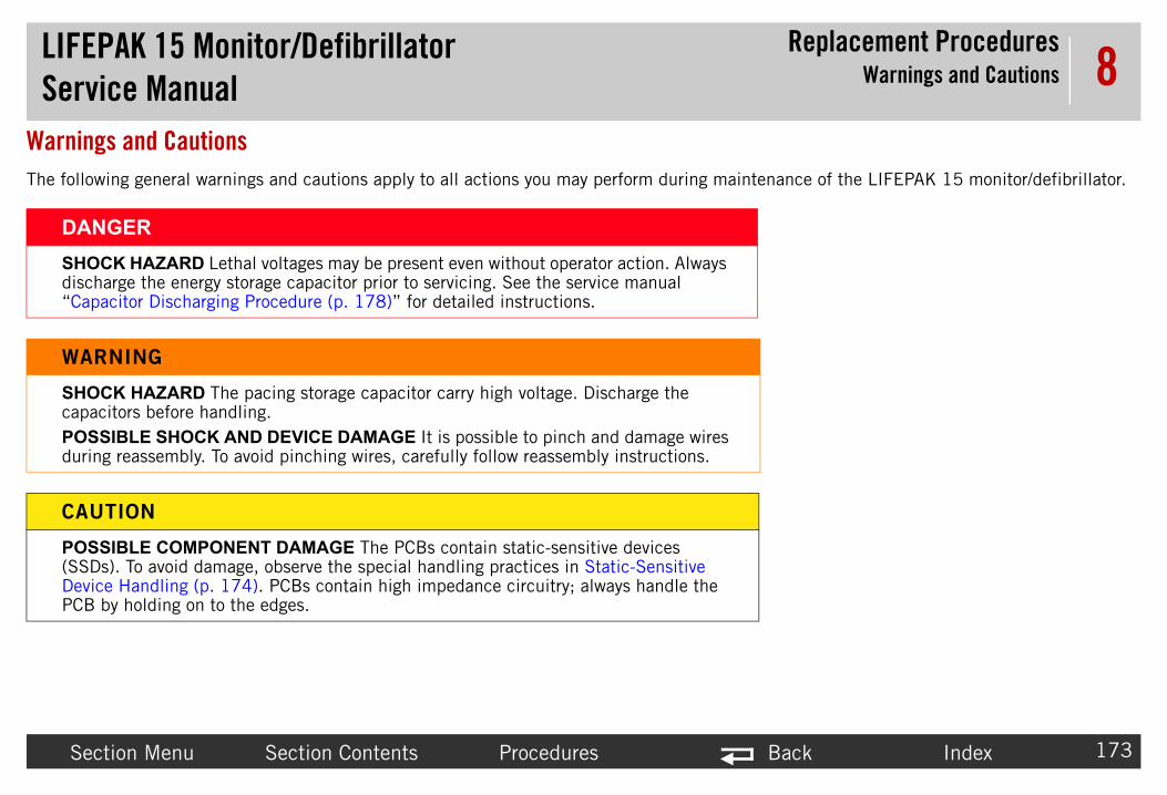
LIFEPAServic
Replacement ProceduresWarnings and Cautions
Sectio Back Index 173
8Warnings The followin intenance of the LIFEPAK 15 monitor/defibrillator.
DANGSHOCKdischarg“Capaci
WARN
SHOCKcapacitoPOSSIBduring r
CAUTI
POSSIB(SSDs).Device HPCB by
K 15 Monitor/Defibrillatore Manual
n Menu Section Contents Procedures
and Cautionsg general warnings and cautions apply to all actions you may perform during ma
ER HAZARD Lethal voltages may be present even without operator action. Always e the energy storage capacitor prior to servicing. See the service manual tor Discharging Procedure (p. 178)” for detailed instructions.
ING
HAZARD The pacing storage capacitor carry high voltage. Discharge the rs before handling.LE SHOCK AND DEVICE DAMAGE It is possible to pinch and damage wires
eassembly. To avoid pinching wires, carefully follow reassembly instructions.
ON
LE COMPONENT DAMAGE The PCBs contain static-sensitive devices To avoid damage, observe the special handling practices in Static-Sensitive
andling (p. 174). PCBs contain high impedance circuitry; always handle the holding on to the edges.

LIFEPAServic
Replacement ProceduresStatic-Sensitive Device Handling
Sectio Back Index 174
8Static-Sen
AbouMany film resistors) can be damaged by the disch s commonly occur when the operator wears synth n damage or destroy static-sensitive devices (SSDs s it.
To pre any open-case test, maintenance, or repair proce
LookSSDs
Use SAlway earth ground.
K 15 Monitor/Defibrillatore Manual
n Menu Section Contents Procedures
sitive Device Handling
t SSD Handling electronic semiconductor devices (such as MOS ICs, FETs, optical isolators, or arge of static electricity. Static charge buildup is very common. Static dischargeetic clothes and transfers the charge to any object touched. These discharges ca). In most cases, the discharge is not even perceptible to the person who cause
vent static discharge damage to SSDs, observe the following precautions duringdures:
for SSD Symbol are identified with the following warning symbol:
tatic-Dissipative Mats perform repair or maintenance on a static-dissipative mat that is connected to
ATTENTION

LIFEPAServic
Replacement ProceduresStatic-Sensitive Device Handling
Sectio Back Index 175
8WearAlway n working on energized equipment or when disch ct against bare skin.
TransTrans kage containing the PCBs as static-sensitive.
KeepKeep area. Connect all electrical equipment, such as sol
Test WTest a g of the test results.
W
S t or w
K 15 Monitor/Defibrillatore Manual
n Menu Section Contents Procedures
a Wrist Straps wear a conductive wrist strap connected to the mat and to ground except whearging high voltage circuits. The strap must be snug enough to make good conta
port and Store PCBs Properlyport and store PCBs in anti-static racks or inside conductive bags. Label the pac
Work Area Static-Freestatic-generating products, such as styrofoam cups or trays, away from the workdering irons and test equipment, to ground with a three-prong plug.
ork Area Routinelyll the anti-static parts of the work area (mat, straps, cables) routinely. Keep a lo
ARNING
HOCK HAZARD Remove the wrist strap when working on energized equipmenhen discharging high voltage circuits.

LIFEPAServic
Replacement ProceduresTools List
Sectio Back Index 176
8Tools ListThe suggeste is as follows:
• St• An• Ca• To
• Po• Po ”)• Po• T1• T1• 4 • 1/• 1/• 9/• 3/• 3/• Sm• Di• Ne• 1.• Se r additional test tools required for
pe
K 15 Monitor/Defibrillatore Manual
n Menu Section Contents Procedures
d list of tools for the LIFEPAK 15 monitor/defibrillator replacement procedures
atic-dissipative mat and wrist strapti-static rack and/or conductive bagspacitor discharge tool (information about Capacitor Discharge Tool (p. 177))rque screwdriver(s)—required torque settings are 2.0, 4.0, 6.8, and 10.0 in-lb
int 0 power drive bit (P0)- Phillips tip for 2-56 screws int 1 power drive bit (P1)- Phillips tip for 4-40 screws (shaft length of 2” and 6int 2 power drive bit (P2)- Phillips tip for 6-32 screws (shaft length of 6”)0 torx power drive bit5 torx power drive bitmm modified thin wall socket for battery pins (Physio-Control tool #3300955)4” socket2” deep socket16” deep socket4” modified deep socket (Physio-Control tool #3305448)8” nutdriverall, slotted screwdriver for label removal
agonal cutteredle nose pliers
5” (hard) putty knifee PIP–Test Equipment Requirements and TCP–Test Equipment Requirements forformance testing
Torque in-lb 2.0 4.0 6.8 10.0
Torque in-oz 32 64 108.8 160
Torque cNm 22.5 45 77 113

LIFEPAServic
Replacement ProceduresCapacitor Discharge Tool
Sectio Back Index 177
8CapacitorA capacitor d ischarging Procedure (p 179).
The illustrati ls used in this example
• 10• 5 • Ne• 8 • Cl• 10• RT
DANGSHOCKbiphasicminutes
RTV silicone rubber sealant
10K, 2W resistor
RTV silicone rubber sealant
10 kV insulation
8AWG wire
neon lamp
5M, 5W resistor
clear plastic tubing
6 inches
Figure 8.1—Capacitor discharge tool
K 15 Monitor/Defibrillatore Manual
n Menu Section Contents Procedures
Discharge Toolischarge tool is used to discharge the energy storage capacitor (see Capacitor D. 178)) and the pacing capacitor (see Discharging the C15 Pacing Capacitor (p.
on shows how the biphasic capacitor discharge tool is constructed. The materia are:
k, 2 W resistor (ten 1 K 2 W), high-voltageM, 5 W resistor, high-voltageon lamp, NE76, NE2, or NE2H
AWG copper wireear plastic tubing, capable of insulating 10 kV kV insulationV silicone rubber sealant
ER HAZARD Capacitor discharge tools that are not designed and labeled for use are inadequate for use on biphasic defibrillators and will take several to discharge the energy capacitor.
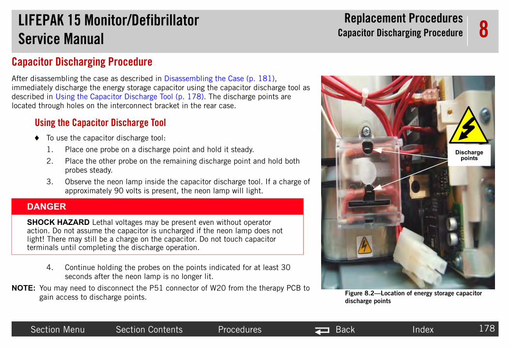
LIFEPAServic
Replacement ProceduresCapacitor Discharging Procedure
Sectio Back Index 178
8CapacitorAfter disasseimmediatelydescribed inlocated throu
Using To
1.
2.
3.
4.
NOTE: You gain
DANGSHOCKaction. light! Thtermina
Figure 8.2—Location of energy storage capacitor
discharge points
Discharge points
K 15 Monitor/Defibrillatore Manual
n Menu Section Contents Procedures
Discharging Procedurembling the case as described in Disassembling the Case (p. 181), discharge the energy storage capacitor using the capacitor discharge tool as Using the Capacitor Discharge Tool (p. 178). The discharge points are gh holes on the interconnect bracket in the rear case.
the Capacitor Discharge Tool use the capacitor discharge tool:
Place one probe on a discharge point and hold it steady.
Place the other probe on the remaining discharge point and hold both probes steady.
Observe the neon lamp inside the capacitor discharge tool. If a charge of approximately 90 volts is present, the neon lamp will light.
Continue holding the probes on the points indicated for at least 30 seconds after the neon lamp is no longer lit.
may need to disconnect the P51 connector of W20 from the therapy PCB to access to discharge points.
ER HAZARD Lethal voltages may be present even without operator
Do not assume the capacitor is uncharged if the neon lamp does not ere may still be a charge on the capacitor. Do not touch capacitor
ls until completing the discharge operation.

LIFEPAServic
Replacement Proceduresischarging the C15 Pacing Capacitor
Sectio Back Index 179
8Dischargin
LocaAfter 04) PCB Assembly Replacement (p. 232), imme sing the Capacitor Discharge Tool (p. 178)). The d
Capacitor Discharge Tool
(p. 177)
R5
R4
R20
R12
4
Area Detail
Figure
K 15 Monitor/Defibrillatore Manual D
n Menu Section Contents Procedures
g the C15 Pacing Capacitor
tion of Discharge Pointsremoving the system and therapy PCBs as described in System (A01)/Therapy (Adiately discharge the Pacing Capacitor using the capacitor discharge tool (see Uischarge points are located at resistors R5 and R20 on the therapy PCB.
CR33
Therapy PCB
8.3—Pacing capacitor discharge points

LIFEPAServic
Replacement Proceduresnd Restoring the Setup Configuration
Sectio Back Index 180
8Saving andBefore begin g either of the following methods:
• Th llator Software Solutions Configuration Setup To
• Th and then manually reconfigure the device.NOTE ndows®-based application designed to assist
You can download the tool from Physio-
Print To
1.
2. printout for future reference.
3.
Resto To
1.
2. u and revise as necessary to match the printout. The l, Manual Mode, AED Mode, and so forth). See the our device.
3.
K 15 Monitor/Defibrillatore Manual Saving a
n Menu Section Contents Procedures
Restoring the Setup Configuration ning any repair action, the existing setup configuration should be preserved usin
e best method is to store setup options to a computer using the LIFEPAK Defibriol before performing service.e second method is to print the existing setup configuration, complete repairs, : The LIFEPAK Defibrillator Software Solutions Configuration Setup Tool is a Wi
you in managing the setup options in your LIFEPAK 15 monitor/defibrillator. Control.com.
ing the Setup Configuration print the setup configuration:
Display the Setup mode (see Setup Mode (p. 92)).
Select PRINT DEFAULTS to print the device setup configuration. Save this
Turn the device OFF.
ring the Setup Manually restore the setup configuration manually:
Display the Setup menu.
Using the printout from the preceding steps, check the settings in each menprintout items are organized in the same manner as the Setup menu (GeneraLIFEPAK 15 Monitor/Defibrillator Setup Options instructions provided with y
Turn the device OFF.

LIFEPAServic
Replacement ProceduresDisassembling the Case
Sectio Back Index 181
8DisassembRefer to Fron 99).
To disas
1. If a
2. Rethe
3. Rethe
4. Rethe
5. Refro
Figure 8.4—Bumper screw locations
Front bumper screws
Rear bumper screws
K 15 Monitor/Defibrillatore Manual
n Menu Section Contents Procedures
ling the Caset Parts Diagrams and Parts List (p. 377) and Rear Diagrams and Parts List (p. 3
semble the case halves: 12 steps, (Page 1 of 3)
pplicable, remove carrying case.
move all cables and patient connections, and then remove batteries.
move the four front mounting screws (3207361-375) from bumpers.
move the four rear mounting screws (3207361-375) from bumpers.
move the bumpers (3207307-001 and 3206968-000) m the case and set aside.

LIFEPAServic
Replacement ProceduresDisassembling the Case
Sectio Back Index 182
8
6. Lapre(20
7. Hoonab
DANG
SHOCKoperatoservicin(p. 178
Figure 8.5—Screw locations
To disas
screw locations
screw locations
screw locations
Remove 14 screws from rear of case
K 15 Monitor/Defibrillatore Manual
n Menu Section Contents Procedures
y the defibrillator face-down on a protective surface to vent damage, and then remove the 14 case screws 1407-069). Discard the screws.
lding the case halves together, position the device face-up your work surface. Lift the front case assembly slightly ove the rear to access the connecting cables.
ER
HAZARD Lethal voltages may be present even without r action. Always discharge the energy storage capacitor prior to g. See the service manual “Capacitor Discharging Procedure )” for detailed instructions.
semble the case halves: (Continued) 12 steps, (Page 2 of 3)
screw locations

LIFEPAServic
Replacement ProceduresDisassembling the Case
Sectio Back Index 183
8
8. Dis(W9.2
9. Dis(32Fig
10. DisP245
11. Se
12. BecapPro
sconnection points
To disas
Disconnect P2 flex cable
Disconnect P23 ribbon cable
Disconnect J24 therapy cable
Lift connector tab to disconnect cable
K 15 Monitor/Defibrillatore Manual
n Menu Section Contents Procedures
connect the P2 system/interface flex cable connector 04) (3206991-003) from the system PCB (see Figure 2 on p. 444) in the rear case.
connect the P23 therapy ribbon cable connector (W11) 07044-002) in the front case from the therapy PCB (see ure 9.24 on p. 446).
connect the J24 therapy cable connector (W11) from the 4 transfer relay connector (A13) (see Figure 9.33 on p. 5).
parate the front and rear cases halves.
fore continuing any further, discharge the energy storage acitor using the discharge tool (see Capacitor Discharging cedure (p. 178)).
Figure 8.6—Di
semble the case halves: (Continued) 12 steps, (Page 3 of 3)

LIFEPAServic
Replacement ProceduresReassembling the Case
Sectio Back Index 184
8Reassemb
To reass
1. Po
2. Co(32(Fi
3. Cotra Connect P23
ribbon cable
Connect J24 therapy cable
K 15 Monitor/Defibrillatore Manual
n Menu Section Contents Procedures
ling the Case
emble the case halves: 13 steps, (Page 1 of 5)
sition the front case over the rear case.
nnect the P23 therapy ribbon cable connector (W11) 07044-002) from the front case to J23 of therapy PCB
gure 9.24 on p. 446).
nnect the J24 6-pin block therapy cable connector (W11) to P24 nsfer relay connector (A13).

LIFEPAServic
Replacement ProceduresReassembling the Case
Sectio Back Index 185
8
4. Caconrea
5. Enedtogthe
CAUT
POSSIwires a(see FigPOSSIsurfacefasteniPREVEspecificscrews specifie
To reass
Connect P2 flex cable
Connector tab ng closure, route py wires away case edges
Connection points
K 15 Monitor/Defibrillatore Manual
n Menu Section Contents Procedures
refully connect the P2 system/interface flex cable nector (W04) (3206991-003) to the system PCB in the r case (Figure 9.22 on p. 444).
sure the case seal is in place in the groove along outside ge of front case. Fold the front and rear case halves ether. Route the therapy cable wires away from the edge of case to avoid pinching.
ION
BLE COMPONENT DAMAGE - Ensure the therapy cable re routed away from the edge of case to avoid wire pinching ure 8.6 on p. 183).
BLE MOISTURE LEAKAGE - Visually inspect the mating s between the front and the rear case halves before and after ng them together to ensure that they are even.NT VIBRATION DAMAGE In order to meet vibration ations (for example, prevent loosening of case screws), use new (201407-069) when assembling the case and torque to d value.
emble the case halves: (Continued) 13 steps, (Page 2 of 5)
Duritherafrom
Figure 8.7—

LIFEPAServic
Replacement ProceduresReassembling the Case
Sectio Back Index 186
8
6. Insusi
Figure 8.8—Screw locations
To reass
screw locations
screw locations
screw locations
Install 14 new screws in rear of case
K 15 Monitor/Defibrillatore Manual
n Menu Section Contents Procedures
tall 14 new screws (201407-069); torque to 10.0 in-lb ng a P2 bit.
emble the case halves: (Continued) 13 steps, (Page 3 of 5)
screw locations

LIFEPAServic
Replacement ProceduresReassembling the Case
Sectio Back Index 187
8
7. Rescrbit
8. Rescrbit
NORe
Figure 8.9—Bumper screw locations
To reass
Front bumper screws
Rear bumper screws
K 15 Monitor/Defibrillatore Manual
n Menu Section Contents Procedures
install the right corner bumper (3207307-001) with 4 ews (3207361-375); torque to 10.0 in-lb using Torx T-15 .
install the left corner bumper (3206968-000) with 4 ews (3207361-375); torque to 10.0 in-lb using Torx T-15 .
TE: If new bumpers and feet are required, use Guard & Feet pair Kit (MIN 3305431-019) (p. 509).
emble the case halves: (Continued) 13 steps, (Page 4 of 5)

LIFEPAServic
Replacement ProceduresReassembling the Case
Sectio Back Index 188
8
NOTE are installed, or the W04 cable connection le between the front case and rear case. ed in Disassembling the Case (p. 181) and
9. Ins
NOT the next step.
10. If a
11. Tur
• If• If• If w.
12. Co tion Procedures.
13. Err og Codes (p. 115).
To reass
K 15 Monitor/Defibrillatore Manual
n Menu Section Contents Procedures
: If there is no indication of power, either the batteries are dead or no batterieswas not made when the case was reassembled. The W04 cable is the flex cabCheck the batteries and, if they are charged, disassemble the case as describcheck the W04 cable.
tall the batteries.
E: Pay special attention to the SERVICE indicator as you turn on the device in
pplicable, reinstall carrying case.
n the device ON and observe the SERVICE indicator.
the SERVICE indicator is OFF, continue with step 12. the SERVICE indicator is ON, skip to step 13. the device gives no indication that power is on, review information in Note belo
mplete the Test and Calibration Procedures, followed by the Performance Inspec
or codes have been written to the Service Log. Continue to Processing Service L
emble the case halves: (Continued) 13 steps, (Page 5 of 5)

LIFEPAServic
Replacement ProceduresInside Front Case Diagram
Sectio Back Index 189
8Inside FroUse the follo ase (p. 181).
Speaker Assembly
(W17) Replacement
RP
LCD Display Assembly/Interface PCB Cable (W18)
Replacement
Printer Control Keypad (A09)
Replacement-J41
Printer Control Keypad/Interface PCB Cable (W12)
Replacement
bly/Interface e (W16) ment
Transfer(A13) Re
T
ly (A11) t
disassembly screw (typical)
embly (A12) cement
J36
B (A05) ment
J32J34
K 15 Monitor/Defibrillatore Manual
n Menu Section Contents Procedures
nt Case Diagramwing diagram after disassembling the case as described in Disassembling the C
Therapy Connector Cable (W11) Replacement
USB Flex Module (W14) Replacement
Backlight PCB (A08)
Replacement
J02
eplacing the System CB (A01) (rear case)
Main Keypad (A10) Replacement-J39
Main Keypad/Interface PCB Cable (W13) Replacement
Printer AssemPCB Cabl
Replace
Printer Assembly/Chassis Ground Cable
(W19) Replacement
Backlight/Interface PCB Cable (W06) Replacement -J49
Relay Assembly placement (rear case)
Replacing the herapy PCB (A04)
(rear case)
J21
P24/J24
J23
LCD Display AssembReplacemen
J23
J33
Printer AssReplaJ40
System/Interface PCB Cable (W04) Replacement J30
J35
J31 J37
Interface PCReplace

LIFEPAServic
Replacement ProceduresInterface PCB (A05) Replacement
Sectio Back Index 190
8Interface
Inter
ground sscrew
K 15 Monitor/Defibrillatore Manual
n Menu Section Contents Procedures
PCB (A05) Replacement
face PCB Replacement Figures
Figure 8.10—Interface PCB screw locations
screws
trap
screws

LIFEPAServic
Replacement ProceduresInterface PCB (A05) Replacement
Sectio Back Index 191
8
W7 - speaker cable (3009726-03) - J34
W12 - printer control keypad cable (3206989-000) -
J32
W18 - LCD cable (3206990-001) - J36
W04 - sys(32069
W13 - mcable (320
K 15 Monitor/Defibrillatore Manual
n Menu Section Contents Procedures
Figure 8.11—Interface PCB cable connection locations - view 1 of 2
tem flex cable 91-003) - J30
ain keypad 7388-001) - J31

LIFEPAServic
Replacement ProceduresInterface PCB (A05) Replacement
Sectio Back Index 192
8
W06 - backligcable (320699
W16 - printer interface cable (3009724-001) - J35W15 - speed d
switch) cab
K 15 Monitor/Defibrillatore Manual
n Menu Section Contents Procedures
Figure 8.12—Interface PCB cable connection locations - view 2 of 2
ht inverter 2-000) - J37
ial (rotary le - J33

LIFEPAServic
Replacement ProceduresInterface PCB (A05) Replacement
Sectio Back Index 193
8RemoRefer (p. 189).
To front case:
1.
2. igure 8.11 on p. 191 and Figure 8.12 on p. 192):
d interface PCB cable (W13, 3207388-001).rface PCB cable (W06, 3206992-000).
l keypad interface PCB cable (W12, 3206989-
face PCB wire (W17, 3009726-03). cable (W16, 3009724-001).speed dial (W15, 3011128-002).
3. scribed in System/Interface PCB Cable (W04)
4.
5. 90). Discard the screws.
K 15 Monitor/Defibrillatore Manual
n Menu Section Contents Procedures
ving the Interface PCB (A05) to Interface PCB Replacement Figures (p. 190) and Inside Front Case Diagram
remove the interface PCB (3206815) or V2 interface PCB (3306367) from the
Disassemble the case as described in Disassembling the Case (p. 181).
Disconnect the connectors (from top left, counterclockwise) as follows (see F
~ J31 – Spread the connector locking tab and disconnect the main keypa~ J37 – Press the connector locking tab and disconnect the backlight inte~ J36 – Disconnect the LCD interface PCB cable (W18, 3206990-001).~ J32 – Press the connector locking tab and disconnect the printer contro
000).~ J34 – Press the connector locking tab and disconnect the speaker inter~ J35 – Spread the connector locking tabs and eject the printer interface~ J33 – Press the connector locking tab and disconnect the cable for the
(If replacing the interface PCB) Disconnect the System/Interface cable as deReplacement (p. 212).
Remove the screw holding the ground strap. Discard the screw.
Remove the eight remaining screws (202253-761) (see Figure 8.10 on p. 1

LIFEPAServic
Replacement ProceduresInterface PCB (A05) Replacement
Sectio Back Index 194
8InstaRefer (p. 189).
To
ir Kit, V1 (MIN 3305431-005) or Interface
1. 761); torque to 6.8 in-lb (see Figure 8.10 on p.
2. 6.8 in-lb (see Figure 8.10 on p. 190).
3. tabs are positioned to secure their respective
1).
6989-000).
4. terface PCB as described in System/Interface PCB
5.
K 15 Monitor/Defibrillatore Manual
n Menu Section Contents Procedures
lling the Interface PCB (A05) to Interface PCB Replacement Figures (p. 190) and Inside Front Case Diagram
install the interface PCB into the front case:
NOTE: If a new interface PCB is required, install the Interface PCBA RepaPCBA Repair Kit, V2 (MIN 3305431-029).
Attach the interface PCB to the bracket with the eight new screws (202253-190).
Install the ground strap (W19) with one new screw (202253-761); torque to
Install the connectors clockwise, as follows (make sure all connector lockingconnectors) (see Figure 8.11 on p. 191 and Figure 8.12 on p. 192):
~ J31 – Install the main keypad interface PCB cable (W13, 3207388-00~ J37 – Install the backlight interface PCB cable (W06, 3206992-000).~ J36 – Install the LCD interface PCB cable (W18, 3206990-001).~ J32 – Install the printer control keypad interface PCB cable (W12, 320~ J34 – Install the speaker interface PCB wire (W17, 3009726-03).~ J35 – Install the printer interface cable (W16, 3009724-001).~ J33 – Install the speed dial cable (W15, 3011128-002).
If the interface PCB was replaced, install the system/interface cable to the inCable (W04) Replacement (p. 212)
Reassemble the case as described in Reassembling the Case (p. 184).

LIFEPAServic
Replacement ProceduresBacklight PCB (A08) Replacement
Sectio Back Index 195
8Backlight The backligh
• Re• In
Refer to Insi
K 15 Monitor/Defibrillatore Manual
n Menu Section Contents Procedures
PCB (A08) Replacementt PCB replacement consists of:
moving the Backlight PCB (A08) (p. 196)stalling the Backlight PCB (A08) (p. 197)
de Front Case Diagram (p. 189).

LIFEPAServic
Replacement ProceduresBacklight PCB (A08) Replacement
Sectio Back Index 196
8Remo T
1
2
3
4
5
6
ation and cable connection for backlight PCB
screw locations
LCD connection point
LCD connection point
K 15 Monitor/Defibrillatore Manual
n Menu Section Contents Procedures
ving the Backlight PCB (A08)o remove the backlight PCB from the front case:
. Disassemble the case as described in Disassembling the Case (p. 181).
. Remove the interface PCB as described in Removing the Interface PCB (A05) (p. 193).
. Disconnect the backlight/interface PCB cable (W06) (3206992-000). Press the connector locking tab and disconnect the W06 cable from the interface PCB at J37. Then place even pressure on the cable and ease the W06 cable out of the connector on the Backlight PCB.
. Remove the two backlight inverter mounting screws (202253-761). Discard the screws.
. Lift the backlight inverter off of the display assembly and disconnect the two end connectors from the LCD display assembly.
. Remove the inverter cover (3207252-001).
Figure 8.13—Screw loc
W06 - power connector (3206992-000)

LIFEPAServic
Replacement ProceduresBacklight PCB (A08) Replacement
Sectio Back Index 197
8Insta T
1
2
3
4
5
6
7
ation and cable connection for backlight PCB
screw locations
LCD connection point
LCD connection point
K 15 Monitor/Defibrillatore Manual
n Menu Section Contents Procedures
lling the Backlight PCB (A08) o install the backlight PCB into the front case:
NOTE: If a new backlight PCB is required, install the Backlight Inverter Repair Kit (MIN 3305431-012).
. Place the inverter cover (3207252-001) over the backlight PCB.
. Connect the two end connectors to the LCD display assembly.
. Connect the backlight/interface PCB cable (W06) (3206992-000) to backlight power connector.
. Place the backlight inverter on the display assembly and install with two new screws (202253-761); torque to 6.8 in-lb.
. Feed excess length of LCD wires into backlight inverter cover.
. Install the interface PCB as described in Installing the Interface PCB (A05) (p. 194).
. Reassemble the case as described in Reassembling the Case (p. 184).
Figure 8.14—Screw loc
W06 - power connector (3206992-000)

LIFEPAServic
Replacement Procedureser Control Keypad (A09) Replacement
Sectio Back Index 198
8Printer Co
Printe
• Re• In
K 15 Monitor/Defibrillatore Manual Print
n Menu Section Contents Procedures
ntrol Keypad (A09) Replacementr control keypad replacement consists of the following:
moving the Printer Control Keypad (A09) (p. 199)stalling the Printer Control Keypad (A09) (p. 199)
Figure 8.15—Printer control keypad replacement

LIFEPAServic
Replacement Procedureser Control Keypad (A09) Replacement
Sectio Back Index 199
8RemoRefer
To
1. ry one edge of the printer control keypad until it is
2. cable (3206989-000) (see Figure 9.52 on p. 474)
3. W12 cable does not fall back into the front case.
InstaRefer
NOTE printed on the printer control keypad package
To part numbers):
1. e from the printer control keypad cavity on the front
2. .
3.
4. the keypad firmly and evenly into the keypad cavity
K 15 Monitor/Defibrillatore Manual Print
n Menu Section Contents Procedures
ving the Printer Control Keypad (A09) to Figure 8.15 on p. 198.
remove the printer control keypad from outside the front case:
Using a very thin, wide, flat-edged tool (example, 1.5” putty knife), gently preleased from its adhesive mount. Take care not to damage the case.
Pull the printer control keypad away from the case, extending part of the W12through the keypad opening.
Disconnect the W12 cable from printer control keypad at J41. Make sure the
lling the Printer Control Keypad (A09) to Figure 8.15 on p. 198.
: Before installing the new printer control keypad, verify that the shelf-life date has not expired.
install the new printer control keypad (see Table 9.11 on page 418 for keypad
Using a soft, lint-free cloth and isopropyl alcohol, gently remove old adhesivcase.
Connect the W12 cable (3206989-000) to the printer control keypad at J41
Check that connector locking tab is securely latched.
Remove the protective covering from the keypad adhesive surface and press on the front case.

LIFEPAServic
Replacement ProceduresMain Keypad (A10) Replacement
Sectio Back Index 200
8Main Keyp
Main
• Re• In
V1 keyp
K 15 Monitor/Defibrillatore Manual
n Menu Section Contents Procedures
ad (A10) Replacementkeypad replacement consists of the following:
moving the Main Keypad (A10) (p. 201)stalling the Main Keypad (A10) (p. 201)
Figure 8.16—Main keypad replacement
ad V2 keypad

LIFEPAServic
Replacement ProceduresMain Keypad (A10) Replacement
Sectio Back Index 201
8RemoRefer
To
1. one edge of the main keypad until it is released
2. ough the keypad opening.
3. igure 9.53 on p. 475) from main keypad at J39.
InstaRefer
NOTE the main keypad package has not expired.
To rs):
1. rom the main keypad cavity on the front case.
2.
3.
4. e keypad firmly and evenly into the keypad cavity
K 15 Monitor/Defibrillatore Manual
n Menu Section Contents Procedures
ving the Main Keypad (A10) to Figure 8.16 on p. 200.
remove the main keypad from outside the front case:
Using a very thin, wide, flat-edged tool (example, 1.5” putty knife), gently pry from its adhesive mount. Take care not to damage the case.
Pull the main keypad away from the case, extending part of the W13 cable thr
Spread the locking tabs and disconnect the W13 cable (3207388-001) (see FMake sure the W13 cable does not fall back into the front case.
lling the Main Keypad (A10) to Figure 8.16 on p. 200.
: Before installing the new main keypad, verify that the shelf-life date printed on
install the new main keypad (see Table 9.12 on page 420 for keypad part numbe
Using a soft, lint-free cloth and isopropyl alcohol, gently remove old adhesive f
Connect the W13 cable (3207388-001) to the main keypad at J39.
Check that connector locking tab is securely latched.
Remove the protective covering from the keypad adhesive surface, and press thon the front case.

LIFEPAServic
Replacement ProceduresDisplay Shield Replacement
Sectio Back Index 202
8Display ShRefer to Insi
screw locations
K 15 Monitor/Defibrillatore Manual
n Menu Section Contents Procedures
ield Replacementde Front Case Diagram (p. 189) and Figure 9.5 (p. 378).
Figure 8.17—Display shield screw locations

LIFEPAServic
Replacement ProceduresDisplay Shield Replacement
Sectio Back Index 203
8RemoRefer
To
1.
2.
InstaRefer
To
it (MIN 3305431-018) (p. 508).
1. free before installing.
2. a T10 bit.
3. 14 on page 425) is required. Clean display shield
K 15 Monitor/Defibrillatore Manual
n Menu Section Contents Procedures
ving the Display Lens Shield to Figure 8.17 on p. 202.
remove the display shield from outside the front case:
Remove the four screws (3207367-312) from the display shield.
Lift the display shield off of the front case assembly.
lling the Display Lens Shield to Figure 8.17 on p. 202.
install the display shield onto the front case:
NOTE: If new display shield is required, install the Display Shield Repair K
Make sure the display lens surface and shield are completely clean and dust
Install the shield with four screws (3207367-312); torque to 6.8 in-lb using
If installing a new display lens shield, Label Set 3207318-XXX (see Table 9.frame with isopropyl alcohol and install label number 10.

LIFEPAServic
Replacement Procedures Display Assembly (A11) Replacement
Sectio Back Index 204
8LCD Displa
The L
• Re• In
Refer
screw locations
K 15 Monitor/Defibrillatore Manual LCD
n Menu Section Contents Procedures
y Assembly (A11) ReplacementCD display assembly replacement includes:
moving the LCD Display Assembly (A11) (p. 205)stalling the LCD Display Assembly (A11) (p. 205)
to Inside Front Case Diagram (p. 189).
Figure 8.18—LCD display assembly screw locations

LIFEPAServic
Replacement Procedures Display Assembly (A11) Replacement
Sectio Back Index 205
8Remo To m (p. 189):
1.
2. ) (p. 193).
3. (A08) (p. 196).
4. y Assembly/Interface PCB Cable (W18) (p. 226)
5. screws.
6. with LCD display assembly facing up.
7. the screws.
8.
Insta To
IN 3305431-013) (p. 505).
1. completely clean and dust free before reinstalling.
2. oute LCD wires through Bracket openings.
3. r new screws (202253-761); torque to 6.8 in-lbs.
4.
5. screws (202253-764); torque to 6.8 in-lb.
6. Assembly/Interface PCB Cable (W18) (p. 226)
7. 08) (p. 197).
8. (p. 194).
9.
K 15 Monitor/Defibrillatore Manual LCD
n Menu Section Contents Procedures
ving the LCD Display Assembly (A11) remove the LCD display assembly from the front case (Inside Front Case Diagra
Disassemble the case as described in Disassembling the Case (p. 181).
Remove the interface PCB as described in Removing the Interface PCB (A05
Remove the backlight inverter as described in Removing the Backlight PCB
Remove the display/interface cable as described in Removing the LCD Displa
Remove the four LCD bracket mounting screws (202253-764). Discard the
Remove the LCD mounting bracket from front case and place on workspace
Remove four screws (202253-761) from the LCD display assembly. Discard
Remove the LCD display from the LCD bracket.
lling the LCD Display Assembly (A11) install the LCD display assembly into the front case:
NOTE: If a new LCD display assembly is required, use Display Repair Kit (M
Make sure both the LCD display assembly screen and the front case lens are
Place the LCD mounting bracket on workspace with display side facing up. R
Install the LCD display assembly onto the display mounting bracket with fou
(If installing a new LCD display) Remove protective layer from LCD screen.
Place the LCD mounting bracket in the front case and secure with four new
Install the display/interface cable as described in Installing the LCD Display
Install the backlight inverter as described in Installing the Backlight PCB (A
Install the interface PCB as described in Installing the Interface PCB (A05)
Reassemble the case as described in Reassembling the Case (p. 184).

LIFEPAServic
Replacement ProceduresDisplay Lens Replacement
Sectio Back Index 206
8Display LeRefer to Insi
Remo T
1
2
3
4
5
ns location
K 15 Monitor/Defibrillatore Manual
n Menu Section Contents Procedures
ns Replacementde Front Case Diagram (p. 189) and Figure 9.5 (p. 378).
ving the Display Lenso remove the display lens from outside the front case:
NOTE: Removing the front lens requires high direct pressure to remove. Suggest instead replacing front case; use Front Case Repair Kit (MIN 3305431-023) (p. 511)
. Disassemble the case as described in Disassembling the Case (p. 181)).
. Remove the display shield as described in Removing the Display Lens Shield (p. 203).
. Remove the interface PCB as described in Removing the Interface PCB (A05) (p. 193).
. Remove the LCD assembly as described in Removing the LCD Display Assembly (A11) (p. 205).
. From the inside of front case, push out the display lens.
Figure 8.19—Display le

LIFEPAServic
Replacement ProceduresDisplay Lens Replacement
Sectio Back Index 207
8InstaRefer
To
1. e from lens frame on the front case.
2. n firmly all around edge of display lens.
3. installing LCD assembly.
4. ly (A11) (p. 205).
5. (p. 194).
6.
K 15 Monitor/Defibrillatore Manual
n Menu Section Contents Procedures
lling the Display Lens to Figure 8.19 on p. 206.
install the display lens onto the front case:
Using a soft, lint-free cloth and isopropyl alcohol, gently remove old adhesiv
Remove adhesive liner from display lens and install on front case. Press dow
Make sure the display lens surface is completely clean and dust free before
Install the LCD assembly as described in Installing the LCD Display Assemb
Install the interface PCB as described in Installing the Interface PCB (A05)
Reassemble the case as described in Reassembling the Case (p. 184)).

LIFEPAServic
Replacement ProceduresFront Case Replacement
Sectio Back Index 208
8Front CaseRefer to Insi
K 15 Monitor/Defibrillatore Manual
n Menu Section Contents Procedures
Replacementde Front Case Diagram (p. 189)
Figure 8.20—Front case replacement (V2 unit shown)

LIFEPAServic
Replacement ProceduresFront Case Replacement
Sectio Back Index 209
8DisasRefer
To
1. (A12) (p. 360).
2. ase (p. 181).
3. e Interface PCB (A05) (p. 193). Note that J36 and
4. .18 on p. 204). Discard the screws.
5. cribed in Removing the Printer Control Keypad/
6. Removing the Main Keypad/Interface PCB Cable
7. ssembly (W15) (p. 218).
8. bly (W17) (p. 224).
9. Connector Cable (W11) (p. 214).
10 19 cable) as described in Removing the Printer
K 15 Monitor/Defibrillatore Manual
n Menu Section Contents Procedures
sembling the Front Case to Figure 8.20 on p. 208.
disassemble the front case:
Remove the printer assembly as described in Removing the Printer Assembly
Separate the front and rear case halves as described in Disassembling the C
Perform steps 1 through 3 to disconnect cables as described in Removing thJ37 do not require removal.
Remove the four LCD bracket mounting screws (202253-764) (see Figure 8
Remove the printer control keypad cable from the back of the keypad as desInterface PCB Cable (W12) (p. 216).
Remove the main keypad cable from the back of the keypad as described in (W13) (p. 217).
Remove the speed dial assembly as described in Removing the Speed Dial A
Remove the speaker assembly as described in Removing the Speaker Assem
Remove the therapy connector cable as described in Removing the Therapy
. Remove the printer assembly/interface PCB Cable (includes removal of the WAssembly/Interface PCB Cable (W16) (p. 221).

LIFEPAServic
Replacement ProceduresFront Case Replacement
Sectio Back Index 210
8AssemRefer
T
NOT
NOT
1
l lock.
2 sembly (W15)
3 onnector Cable
4 s described in
K 15 Monitor/Defibrillatore Manual
n Menu Section Contents Procedures
bling the Front Case to Figure 8.20 on p. 208.
o install the new front case: 15 steps, (Page 1 of 2)
E: Use the Front Case Repair Kit (MIN 3305431-023) (p. 511).
E: Transfer the following parts from the old front case to the new front case:~ LCD/interface PCB assembly ~ W15 speed dial assembly~ W17 speaker assembly~ W11 therapy connector~ W16 printer/interface PCB cable~ W12 printer control keypad cable~ W13 main keypad cable~ Printer bracket (3006810-01) with W19 cable
. Install the perimeter seal (804234-03) into the groove on the front case.
NOTE: Thread the perimeter seal approximately 1.5 inches through the seaDo not stretch the seal, as this will result in crimped corners.
. Install the speed dial assembly as described in Installing the Speed Dial As(p. 220).
. Install the therapy connector cable as described in Installing the Therapy C(W11) (p. 214).
. Install the printer assembly/interface PCB Cable (includes the W19 cable) aInstalling the Printer Assembly/Interface PCB Cable (W16) (p. 222).

LIFEPAServic
Replacement ProceduresFront Case Replacement
Sectio Back Index 211
8
5 ly (W17) (p.
6
7 (p. 203).
8 ket in the front
9 talling the
1 rol Keypad
1 . 201).
1
1 208003-000)
1 (A12) (p. 361).
1 ired. Clean the nd 11.
T
K 15 Monitor/Defibrillatore Manual
n Menu Section Contents Procedures
. Install the speaker assembly as described in Installing the Speaker Assemb225).
. Install the display lens as described in Installing the Display Lens (p. 207).
. Install the display shield as described in Installing the Display Lens Shield
. Install the LCD/Interface PCB assembly by installing the LCD mounting braccase and secure with four new screws (202253-764); torque to 6.8 in-lb.
. Reconnect cables to interface PCB by performing step 3 as described in InsInterface PCB (A05) (p. 194).
0. Install the printer control keypad as described in Installing the Printer Cont(A09) (p. 199).
1. Install the main keypad as described in Installing the Main Keypad (A10) (p
2. Reassemble the case as described in Reassembling the Case (p. 184).
3. Clean the front case with isopropyl alcohol, and apply Physio-Control logo (3to the location provided in upper left of front case.
4. Install the printer assembly as described in Installing the Printer Assembly
5. Installing the label set (3207318-XXX, see Table 9.14 on page 425) is requfront case areas with isopropyl alcohol and install label numbers 4, 6, 10 a
o install the new front case: (Continued) 15 steps, (Page 2 of 2)

LIFEPAServic
Replacement Procedureserface PCB Cable (W04) Replacement
Sectio Back Index 212
8System/InRefer to Insi
Remo To on p.
19
1.
2.
Insta To n p.
46
1. bs and
2. nect
Figure 8.21—System/interface PCB
cable connections
to A05 - J30 to A01 - J2
K 15 Monitor/Defibrillatore Manual System/Int
n Menu Section Contents Procedures
terface PCB Cable (W04) Replacementde Front Case Diagram (p. 189).
ving the System/Interface PCB Cable (W04) remove the system/interface PCB W04 cable (3206991-003) (see Figure 8.111 and Figure 9.44 on p. 466) from the front case:
NOTE: Cable solder connections are fragile; keep handling to a minimum.
Disassemble the case as described in Disassembling the Case (p. 181). Thisprocedure removes the W04 cable from the system PCB (A01) at J2.
Disconnect the W04 cable from the interface PCB at J30.
lling the System/Interface PCB Cable (W04) install the system/interface PCB W04 cable (3206991-003) (see Figure 9.44 o6) into the front case:
Snap connector of the System/Interface cable (W04) (3206991-003) over taconnect to interface PCB at J30. Check that connector is fully seated.
Reassemble the case as described in Reassembling the Case (p. 184) to conthe W04 cable to the system PCB (A01) at J2.

LIFEPAServic
Replacement Procedureserface PCB Cable (W06) Replacement
Sectio Back Index 213
8Backlight/Refer to Insi
Remo To p.
46
1.
2. rface
3. tor on
Insta To
1.
2. 37.
3.
P37
P49
to A05 - J37
to A08 - J49
Figure 8.22—Backlight PCB/interface PCB
cable connections
K 15 Monitor/Defibrillatore Manual Backlight/Int
n Menu Section Contents Procedures
Interface PCB Cable (W06) Replacementde Front Case Diagram (p. 189).
ving the Backlight/interface PCB (W06) Cable remove the backlight/interface W06 cable (3206992-000) (see Figure 9.46 on8) from the front case:
Disassemble the case as described in Disassembling the Case (p. 181).
Press the connector locking tab and disconnect the W06 cable from the intePCB at J37.
Place even pressure on the cable and ease the W06 cable out of the connecthe Backlight PCB.
lling the Backlight/interface PCB (W06) Cable install the backlight/interface W06 cable into the front case:
Connect the W06 cable (3206992-000) to the Backlight PCB.
If interface PCB is present, connect the W06 cable to the interface PCB at J
Reassemble the case as described in Reassembling the Case (p. 184).

LIFEPAServic
Replacement Procedures Connector Cable (W11) Replacement
Sectio Back Index 214
8Therapy CRefer to Insi
Remo To case:
1.
2. from
3. from -
Insta T
4 s
1
CAUT
POSSItherapy Figure 8.23—Therapy connector cable
and seal
K 15 Monitor/Defibrillatore Manual Therapy
n Menu Section Contents Procedures
onnector Cable (W11) Replacementde Front Case Diagram (p. 189).
ving the Therapy Connector Cable (W11) remove the therapy connector cable (see Figure 9.51 on p. 473) from the front
Disassemble the case as described in Disassembling the Case (p. 181).
From the outside of the front case, remove the four screws (3207361-375) the therapy connector.
Lift the therapy Connector cable (3207044-002) and therapy mounting sealthe front case. Discard the four screws and therapy mounting seal (3207701000).
lling the Therapy Connector Cable (W11) o install the therapy Connector cable into the front case:
teps, (Page 1 of 2)
NOTE: If therapy connector cable requires replacement, use the Therapy Connector Repair Kit (MIN 3305431-009) (p. 503).
. From the outside of the front case, install a new therapy mounting seal (3207701-000) into the front case.
ION
BLE MOISTURE LEAKAGE When installing the therapy connector, use a new mounting seal (3207701-000) to help prevent ingress of fluids.

LIFEPAServic
Replacement Procedures Connector Cable (W11) Replacement
Sectio Back Index 215
8
2
3 61-
4
T
(Con
K 15 Monitor/Defibrillatore Manual Therapy
n Menu Section Contents Procedures
. From the outside of the front case, insert the new therapy Connector cable through the therapy mounting seal and front case.
. Secure the therapy connector to the front case with four new screws (32073375); torque to 10 in-lb using a T15 bit.
. Reassemble the case as described in Reassembling the Case (p. 184).
o install the therapy Connector cable into the front case:
tinued) 4 steps, (Page 2 of 2)

LIFEPAServic
Replacement Proceduresol Keypad/Interface PCB Cable (W12)
Replacement
Sectio Back Index 216
8Printer CoRefer to Insi
RemoSee d
To
1.
2. e
3. e printer
Insta To
1. .
2. 32.
3.
P32
P41to A09 - J41
to A05 - J32
Figure 8.24—Printer control keypad/interface
PCB cable connections
K 15 Monitor/Defibrillatore Manual Printer Contr
n Menu Section Contents Procedures
ntrol Keypad/Interface PCB Cable (W12) Replacementde Front Case Diagram (p. 189).
ving the Printer Control Keypad/Interface PCB Cable (W12)iagram on Figure 9.29 on p. 451.
remove the W12 cable (3206989-000) from the front case:
Disassemble the case as described in Disassembling the Case (p. 181).
Press the connector locking tab, and then disconnect the W12 cable from thinterface PCB at J32.
Press the connector locking tab, and then disconnect the W12 cable from thcontrol keypad at J41.
lling the Printer Control Keypad/Interface PCB Cable (W12) install the W12 cable into the front case:
Connect the W12 cable (3206989-000) to the printer control keypad at J41
If interface PCB is present, connect the W12 cable to the interface PCB at J
Reassemble the case as described in Reassembling the Case (p. 184).

LIFEPAServic
Replacement Procedureserface PCB Cable (W13) Replacement
Sectio Back Index 217
8Main KeypRefer to Insi
Remo To
1.
2. ct the W13
3. ct the W13
Insta To
1. king tabs
2. 31 (“snap”
3.
P39 P31
to A10 - J39 to A05 - J31
Figure 8.25—Main keypad/interface
PCB cable connections
K 15 Monitor/Defibrillatore Manual Main Keypad/Int
n Menu Section Contents Procedures
ad/Interface PCB Cable (W13) Replacementde Front Case Diagram (p. 189).
ving the Main Keypad/Interface PCB Cable (W13) remove the W13 cable (3207388-001) from the front case:
Disassemble the case as described in Disassembling the Case (p. 181).
Press the connector locking tabs to unlock the connector, and then disconnecable from the interface PCB at J31.
Press the connector locking tabs to unlock the connector, and then disconnecable from the main keypad at J39.
lling the Main Keypad/Interface PCB Cable (W13) install the W13 cable (3207388-001) into the front case:
Connect the W13 cable to the main keypad at J39 (“snap” the connector locinto the locked position).
If interface PCB is present, connect the W13 cable to the interface PCB at Jthe connector locking tabs into the locked position).
Reassemble the case as described in Reassembling the Case (p. 184).

LIFEPAServic
Replacement Proceduresed Dial Assembly (W15) Replacement
Sectio Back Index 218
8Speed Dia
Remo T
4
1
2
3
cable connection
to J33
re 8.26—Speed dial cable
switch knob from
front
re 8.26—Speed dial knob
K 15 Monitor/Defibrillatore Manual Spe
n Menu Section Contents Procedures
l Assembly (W15) Replacement
ving the Speed Dial Assembly (W15)o remove the speed dial assembly (3011128-002) (see Figure 9.54 on p. 76) from the front case: 5 steps, (Page 1 of 2)
. Disassemble the case as described in Disassembling the Case (p. 181).
. Press the connector locking tab, and then disconnect the speed dial assembly cable from the interface PCB at J33.
. From the outside of the front case, grasp the speed dial assembly knob (3207030-000) and, with steady smooth force, pull the knob off the speed dial assembly shaft. Use a gripping tool if necessary, taking care to avoid any damage.
Figu
Figu

LIFEPAService
Replacement Proceduresed Dial Assembly (W15) Replacement
Sectio Back Index 219
8
4
5
T4
switch retaining
nut
ure 8.27—Nut and lock washer
K 15 Monitor/Defibrillator Manual Spe
n Menu Section Contents Procedures
. From the outside of the case, loosen and remove the nut and lock washer (part of the speed dial assembly) from the speed dial assembly shaft.
. From the inside of the case, pull the speed dial assembly away from the case and remove it.
o remove the speed dial assembly (3011128-002) (see Figure 9.54 on p. 76) from the front case: (Continued) 5 steps, (Page 2 of 2)
Fig

LIFEPAServic
Replacement Procedurestalling the Speed Dial Assembly (W15)
Sectio Back Index 220
8Installing th
ToDi
NOTE
1.
2.
3.
4.
5.
rear of switch, orient with cable toward PCB
Figure 8.28—Speed dial assembly
cable connection to J33
Figure 8.29—Speed dial cable
K 15 Monitor/Defibrillatore Manual Ins
n Menu Section Contents Procedures
e Speed Dial Assembly (W15)
install the speed dial assembly into the front case (Inside Front Case agram (p. 189)):
: When installing a new speed dial assembly (3011128-002) use External Hardware Repair Kit (MIN 3305431-016) (p. 507).
Insert the speed dial assembly from inside the front case so that the cable is extending away from the perimeter seal.
Attach the speed dial assembly shaft to the front case with the nut and lock washer (torque to 10 in-lb using a 9/16 deep socket).
Push the knob (3207030-000) onto the speed dial assembly shaft from the outside of the front case (see Figure 8.27 on p. 219).
If interface PCB is present, connect the speed dial assembly to the interface PCB at J33.
Reassemble the case as described in Reassembling the Case (p. 184).

LIFEPAServic
Replacement Procedureserface PCB Cable (W16) Replacement
Sectio Back Index 221
8Printer AsRefer to Insi
Remo To 478) from the
fro
1.
2. erface PCB at
3. ctor bracket.
4. 10-01) on the he screw.
5. ctor on the -00).
P40
P35
to A12 - J40
to A05 - J35
Figure 8.30—Printer / Interface
PCB connection
K 15 Monitor/Defibrillatore Manual Printer Assembly/Int
n Menu Section Contents Procedures
sembly/Interface PCB Cable (W16) Replacementde Front Case Diagram (p. 189).
ving the Printer Assembly/Interface PCB Cable (W16) remove the printer/interface PCB cable (3009724-001) (see Figure 9.56 on p. nt case:
Disassemble the case as described in Disassembling the Case (p. 181).
Spread the connector locking tabs and eject the W16 cable from the A05 intJ35.
Disconnect the W19 cable ground terminal from the printer assembly conne
Remove the retaining screw (3207337-312) and connector bracket (30068A12 printer assembly housing that secures the W16 cable at P40. Discard t
With a flat edged tool, gently pry the W16 cable at P40 out of the J40 conneprinter assembly. Remove and discard the rubber moisture gasket (3006809

LIFEPAServic
Replacement Procedureserface PCB Cable (W16) Replacement
Sectio Back Index 222
8InstaRefer
To
NOTE rdware Repair Kit (MIN 3305431-016) (p.
1. nect the W16 cable to the printer assembly at J40. r W16 cable and secure it with one new screw with
2. bly connector bracket.
3. 35.
4.
K 15 Monitor/Defibrillatore Manual Printer Assembly/Int
n Menu Section Contents Procedures
lling the Printer Assembly/Interface PCB Cable (W16) to Figure 8.30 on p. 221.
install the printer/interface PCB cable (W16) into the front case:
: When installing printer/interface PCB cable (3009724-001) use External Ha507).
Install a new rubber moisture gasket (3006809-00) onto the W16 cable. ConPlace the printer assembly connector bracket (3006810-01) over the printewasher (3207337-312) into the front case; torque to 6.8 in-lb.
Connect the W19 cable ground terminal (3009726-03) to the printer assem
If interface PCB is present, connect the W16 cable to the interface PCB at J
Reassemble the case as described in Reassembling the Case (p. 184).

LIFEPAServic
Replacement Procedurespeaker Assembly (W17) Replacement
Sectio Back Index 223
8Speaker ARefer to Insi
tion
K 15 Monitor/Defibrillatore Manual S
n Menu Section Contents Procedures
ssembly (W17) Replacement de Front Case Diagram (p. 189).
Figure 8.31—Speaker assembly replacement cable connection and screw loca
cable connection
to J34
screw location
retaining spring

LIFEPAServic
Replacement Procedurespeaker Assembly (W17) Replacement
Sectio Back Index 224
8RemoRefer
To the fro
1.
2. from
3. for the bly.
4. t case.
P34
Figure 8.32—Speaker
Assembly connection
K 15 Monitor/Defibrillatore Manual S
n Menu Section Contents Procedures
ving the Speaker Assembly (W17) to Figure 8.31 on p. 223.
remove the Speaker Assembly (3009726-03) (see Figure 9.57 on p. 479) fromnt case:
Disassemble the case as described in Disassembling the Case (p. 181).
Press the connector locking tab, and then disconnect the Speaker Assemblythe interface PCB at J34, if the interface PCB is present.
Remove the screw (3207337-312) securing the spring clamp (3012693-00)W17 Speaker Assembly. Note the orientation of the spring clamp for reassemDiscard the screw.
Set the spring clamp aside, and then lift the Speaker Assembly from the fron

LIFEPAServic
Replacement Procedurespeaker Assembly (W17) Replacement
Sectio Back Index 225
8InstaRefer
To 189)):
NOTE air Kit (MIN 3305431-016) (p. 507).
1. 93-00) with one new screw with washer (3207337-
2. CB at J34.
3.
C
P sure t ess of f
K 15 Monitor/Defibrillatore Manual S
n Menu Section Contents Procedures
lling the Speaker Assembly (W17) to Figure 8.31 on p. 223.
install the Speaker Assembly into the front case (Inside Front Case Diagram (p.
: When installing speaker assembly (3009726-03) use External Hardware Rep
Set the Speaker Assembly into the case and secure the spring clamp (30126312); torque to 6.8 in-lb.
NOTE: Make sure you do not pinch the wires during reassembly.
If interface PCB is present, connect the Speaker Assembly to the interface P
Reassemble the case as described in Reassembling the Case (p. 184).
AUTION
OSSIBLE MOISTURE LEAKAGE When installing the Speaker Assembly, makehe speaker felt moisture barrier is in place on the front case to help prevent ingrluids. When replacing the speaker, do not touch the speaker felt.

LIFEPAServic
Replacement Procedures Assembly/Interface PCB Cable (W18)
Replacement
Sectio Back Index 226
8LCD DisplaRefer to Insi
Remo To
th
1.
2.
3.
Insta To
fro
1.
2.
3.gure 8.33—LCD cable connection
K 15 Monitor/Defibrillatore Manual LCD Display
n Menu Section Contents Procedures
y Assembly/Interface PCB Cable (W18) Replacementde Front Case Diagram (p. 189).
ving the LCD Display Assembly/Interface PCB Cable (W18) remove the LCD display/interface PCB W18 cable (3206990-001) from e front case:
Disassemble the case as described in Disassembling the Case (p. 181).
Remove the W18 cable (3206990-001) (see Figure 9.58 on p. 480) from the interface PCB at J36.
Place even pressure on the cable ribbon and ease the W18 cable out of the connector on the LCD display assembly.
lling the LCD Display Assembly/Interface PCB Cable (W18) install the LCD display/interface PCB W18 cable (3206990-001) into the nt case:
Connect the W18 cable to the connector on the LCD display assembly.
If interface PCB is present, connect the W18 cable to the interface PCB at J36.
Reassemble the case as described in Reassembling the Case (p. 184).Fi

LIFEPAServic
Replacement Proceduressis Ground Cable (W19) Replacement
Sectio Back Index 227
8Printer AsRefer to Insi
Remo To on p. 481)
fro
1.
2. CB and LCD
3. ctor bracket.
Insta To :
1. racket.
2. et (3006810-
3.
chassis ground
Printer Assembly (A12)
Figure 8.34—printer cable
connection
K 15 Monitor/Defibrillatore Manual Printer Assembly/Chas
n Menu Section Contents Procedures
sembly/Chassis Ground Cable (W19) Replacementde Front Case Diagram (p. 189).
ving the Printer Assembly/Chassis Ground Cable (W19) remove the printer/chassis ground W19 cable (3009726-01) (see Figure 9.59 m the front case:
Disassemble the case as described in Disassembling the Case (p. 181).
Remove the screw (202253-761) securing the W19 cable to the interface Pdisplay assembly bracket (3006810-01). Discard the screw.
Disconnect the W19 cable ground terminal from the printer assembly conne
lling the Printer Assembly/Chassis Ground Cable (W19) install the printer/chassis ground W19 cable (3009726-01) into the front case
Connect the W19 cable ground terminal to the printer assembly connector b
Secure the W19 cable to the interface PCB and LCD display assembly brack01) with one new screw (202253-761); torque to 6.8 in-lb.
Reassemble the case as described in Reassembling the Case (p. 184).

LIFEPAServic
Replacement ProceduresInside Rear Case Diagrams
Sectio Back Index 228
8Inside ReaThe inside re
• Re• Sy• En
Numerous re
K 15 Monitor/Defibrillatore Manual
n Menu Section Contents Procedures
r Case Diagramsar case diagrams include the following:
ar Case Overview (p. 229)stem (A01)/Therapy (A04) PCBs Removed (p. 230)ergy Transfer Detail Diagram (p. 231)
pair procedures refer to these diagrams.

LIFEPAServic
Replacement ProceduresInside Rear Case Diagrams
Sectio Back Index 229
8RearUse t e (p. 181).
02
USB(W14
P
ECG C(W07
J30
Interface PCB (A05) Replacement(front case)
System/Interface PCB Cable (W04) Replacement
ParR
) t
(A14) Biphasic Module (A22)/Inductive Resistor
(A14) Replacement
Replacing the Therapy PCB (A04)-J23
Therapy Connector Cable (W11) Replacement
P24/J24
(front case)
System (A01)/Therapy (A04) PCB Assembly
Replacement
d
)/Inductive ment
NIBR
CO
1
InvaConn(W33
SpO(W
(V2)Cable A
Re
K 15 Monitor/Defibrillatore Manual
n Menu Section Contents Procedures
Case Overviewhis diagram after disassembling the case as described in Disassembling the Cas
Energy Storage Capacitor (A15) Replacement
OEM PCB (A06) Replacement
J04
J
Replacing the System PCB (A01)
J50
Flex Module ) Replacement
J01
ower/System PCB Cable (W01) Replacement
Coin Battery Replacement
onnector Cable ) Replacement
J06
ameter Bezel eplacement
InterconnectBracket (A17Replacemen
isassembly screw (typical)
(W22) Biphasic Module (A22Resistor (A14) Replace
P Connector eplacement
2 Inlet Connector Cable (W28) Replacement
J5
J07
ECG
SpO2
CO2
NIBP
P1
P2
sive Pressure ector Assembly ) Replacement
2 Connector Cable 22) Replacement
Temperature ssembly (W35) placement

LIFEPAServic
Replacement ProceduresInside Rear Case Diagrams
Sectio Back Index 230
8SysteUse t in System (A01)/Therapy (A04) PCB Assem
7 Interconnect Bracket
Inductive esistor
P24
A03 PowPCB
citor bracket
ssemblyw (typical)
Biphasic odule
CO2, SpO2PC
K 15 Monitor/Defibrillatore Manual
n Menu Section Contents Procedures
m (A01)/Therapy (A04) PCBs Removedhis diagram after removing the A01 system and A04 therapy PCBs as describedbly Replacement (p. 232).
A15 Energy Storage
Capacitor
A06 OEM PCB Module
A1
A14R
A13 Transfer Relay Assemblyer
J17
J08
J16/J25
J13J15
J14
J11
JP5JP1
J12
capa
disascre
A13M
Relay bracket
, and NIBP Bs
J26

LIFEPAServic
Replacement ProceduresInside Rear Case Diagrams
Sectio Back Index 231
8EnergUse ttransfmodustoragA17 i
Table 8.1—I
A17 Interconn
Capacitor Neg
Capacitor Pos
A22 Biphasic
A22 Biphasic
A22 Biphasic
Relay A1 (7)
Relay B1 (104
J21+
J101J103J105J108J102J104J107 Not Used
P24
A14 Inductive Resistor
A22 Biphasic Module
A15 Energy Storage Capacitor
To Therapy PCB - P21
P24 To Therapy Connector
on Front Case
2 3
5 6
8 9
K 15 Monitor/Defibrillatore Manual
n Menu Section Contents Procedures
y Transfer Detail Diagramhis diagram to replace the er relay assembly, biphasic le/inductive resistor, energy e capacitor, and nterconnect bracket.
nterconnect bracket
ect Bracket Chart
1 A17 Pin 1
4 A17 Pin 4
J101 A17 Pin 3
J105 A17 Pin 6
J103 A17 Pin 9
A17 Pin 7
) A22 BTE J104
X1 X2
B3 B2 B1 A1 A2 A3
A17 Interconnect Bracket
–
J18
J19
J22
cable tie (222) (6 places)
large cable tie (224)+
–
A13 Transfer Relay Assembly
To Therapy PCB - P18
To Therapy PCB - P22
To Therapy PCB - P19 1
4
7
The wire colors are not the actual wire colors, but are for graphic representation only.

LIFEPAServic
Replacement Proceduresapy (A04) PCB Assembly Replacement
Sectio Back Index 232
8System (AThe system/t /Therapy PCB Assembly Diagrams and Parts List (p. 387) and Fig connection diagram of the therapy PCB and Figure 9.22 on p. 4
Replacemen
• Re• Se• Re• Se• Re• In
K 15 Monitor/Defibrillatore Manual System (A01)/Ther
n Menu Section Contents Procedures
01)/Therapy (A04) PCB Assembly Replacementherapy PCB assembly is removed as a unit and then separated. Refer to Systemure 9.9 (p. 388) for diagrams of this assembly. See Figure 9.24 on p. 446 for a44 for a connection diagram of the system PCB.
t consists of the following procedures:
moving the System (A01)/Therapy (A04) PCB Assembly (p. 233)parating the System PCB (A01) (p. 244)placing the System PCB (A01) (p. 246)parating the Therapy PCB (A04) (p. 247)placing the Therapy PCB (A04) (p. 250)stalling the System (A01)/Therapy (A04) PCB Assembly (p. 239)

LIFEPAServic
Replacement Proceduresapy (A04) PCB Assembly Replacement
Sectio Back Index 233
8Remo
T (Page 1 of 6)
1
2
power/tem PCB cable
x r
CG cable
emp cable resent)
.35—System
nectors
K 15 Monitor/Defibrillatore Manual System (A01)/Ther
n Menu Section Contents Procedures
ving the System (A01)/Therapy (A04) PCB Assembly
o remove the system/therapy PCBs as a single unit from the rear case: 9 steps,
. Disassemble the case as described in Disassembling the Case (p. 181).
. Disconnect the connectors on the system PCB as follows:
~ J1 – Press the connector locking tabs and disconnect the power/system PCB cable (W01, 3207692-000).
~ J2 – (The system/interface PCB cable was disconnected during case disassembly (Disassembling the Case (p. 181)).
~ J4 – Disconnect the USB flex connector (W14, 3206966-001).
~ J6 – Disconnect the ECG connector cable (W7, 3007991-007).
~ (If present) J7 – Disconnect the IP connector of the IP wire harness (W33, 3200466-01).
~ (If present) J7 – Disconnect the temperature connector of the temperature cable (W35, 3303936-001).
J1sys
J4 USB fleconnecto
J6 E
J7 IP/T(if p
Figure 8
PCB con

LIFEPAServic
Replacement Proceduresapy (A04) PCB Assembly Replacement
Sectio Back Index 234
8
Figure 8.36—W20 biphasic cable
T d) 9 steps, (Page 2 of 6)
asic to cable ctor
asic to cable tor 92)
K 15 Monitor/Defibrillatore Manual System (A01)/Ther
n Menu Section Contents Procedures
~ J106 (A22 biphasic PCB) - Disconnect the BTE cable from the biphasic PCB (W20, 3011792-005).
NOTE: The 3011792 BTE to therapy PCB cable is used as the replacement cable after the release of LIFEPAK15 V2.
o remove the system/therapy PCBs as a single unit from the rear case: (Continue
J106 biphtherapy
conne
J106 biphtherapy
connec(30117

LIFEPAServic
Replacement Proceduresapy (A04) PCB Assembly Replacement
Sectio Back Index 235
8
3
4
.37—System/therapy PCB screw locations
T d) 9 steps, (Page 3 of 6)
tem/therapy mounting screws (7 places)
mounting screw with washer (1 place)
K 15 Monitor/Defibrillatore Manual System (A01)/Ther
n Menu Section Contents Procedures
. Remove the seven screws (202253-761) and one screw with washer (3207337-312) that secure the system PCB to the rear case. Discard the screws.
NOTE: The screw that is in the ECG shield can easily be missed as part of screw removal. Ensure that all screws are removed prior to lifting the system/therapy PCB assembly.
. Set the rear case upright and move the system/therapy PCB assembly towards the front of the case to gain access to the rear therapy PCB connectors.
Figure 8
o remove the system/therapy PCBs as a single unit from the rear case: (Continue
sys

LIFEPAServic
Replacement Proceduresapy (A04) PCB Assembly Replacement
Sectio Back Index 236
8
5
6
.38—System/therapy PCB cable connections
T d) 9 steps, (Page 4 of 6)
2 transfer relay J21 transfer relay
K 15 Monitor/Defibrillatore Manual System (A01)/Ther
n Menu Section Contents Procedures
. Disconnect the transfer relay (3201583-001) from the therapy PCB at J22.
. Disconnect the transfer relay (3201583-001) from the therapy PCB at J21.
Figure 8
o remove the system/therapy PCBs as a single unit from the rear case: (Continue
J2

LIFEPAServic
Replacement Proceduresapy (A04) PCB Assembly Replacement
Sectio Back Index 237
8
7
.39—System/therapy PCB cable connections
T d) 9 steps, (Page 5 of 6)
J20 power/therapy PCB cable
8 transfer relay
J19 transfer relay
K 15 Monitor/Defibrillatore Manual System (A01)/Ther
n Menu Section Contents Procedures
. Continue lifting the assembly. Disconnect the following connectors on the therapy PCB in the following order:
~ J18 – Disconnect transfer relay assembly connector (A13, 3201583-001).
~ J19 – Disconnect energy storage capacitor connector (A15, 3008164-002).
~ J20 – Disconnect power/PCB therapy cable (W02, 3009726-05).
Figure 8
o remove the system/therapy PCBs as a single unit from the rear case: (Continue
J1

LIFEPAServic
Replacement Proceduresapy (A04) PCB Assembly Replacement
Sectio Back Index 238
8
8
9
T d) 9 steps, (Page 6 of 6)
K 15 Monitor/Defibrillatore Manual System (A01)/Ther
n Menu Section Contents Procedures
. Lift the system/therapy board assembly out from the rear case. Turn the system/therapy board assembly over to expose the therapy board.
. Immediately discharge the pacing capacitor as described in Discharging the C15 Pacing Capacitor (p. 179). The discharge points are located at resistors R5 and R20 on the therapy board.
o remove the system/therapy PCBs as a single unit from the rear case: (Continue

LIFEPAServic
Replacement Proceduresm (A01)/Therapy (A04) PCB Assembly
Sectio Back Index 239
8Installing th
T
1
2
3
4
power/tem PCB cable
x r
er/PCB e
8.40—System/therapy PCB connections
K 15 Monitor/Defibrillatore Manual Installing the Syste
n Menu Section Contents Procedures
e System (A01)/Therapy (A04) PCB Assemblyo install the system/therapy PCB: 15 steps, (Page 1 of 5)
. Line up the system/therapy assembly with rear case.
. Connect the W14 - USB flex cable (3206966-001) to J4 of the system PCB.
. Connect the W01 - power/system cable to J1 of system PCB.
. Connect the W02 - power/therapy cable from the power PCB P20 (3009726-05) to J20 of the therapy PCB.
J1sys
J4 USB fleconnecto
J20 powtherapy
cabl
Figure

LIFEPAServic
Replacement Proceduresm (A01)/Therapy (A04) PCB Assembly
Sectio Back Index 240
8
5
6
7
8
WARN
POSSIensure
T
nsfer y
nsfer ay
sfer
sfer y
.41—System/therapy PCB cable connections
K 15 Monitor/Defibrillatore Manual Installing the Syste
n Menu Section Contents Procedures
. Connect the 5-pin connector from the A13 - transfer relay P18 to J18 of the therapy PCB.
. Connect the 5-pin connector from the A15 - energy capacitor to J19 of the therapy PCB.
. Connect the 5-pin connector from the A13 - transfer relay P21 to J21 of the therapy PCB.
. Connect the 2-pin connector (red and black wires) from the A13 - transfer relay to J22 of the therapy PCB.
ING
BLE INABILITY TO DELIVER THERAPY Visually inspect to that P22 is fully inserted into the J22 connector.
o install the system/therapy PCB: (Continued) 15 steps, (Page 2 of 5)
J19 trarela
J18 trarel
J22 tranrelay
J21 tranrela
Figure 8

LIFEPAServic
Replacement Proceduresm (A01)/Therapy (A04) PCB Assembly
Sectio Back Index 241
8
9
T
x cable - 51
cable - 06
Figure 8.42—W20 flex cable connections
x cable - 06
K 15 Monitor/Defibrillatore Manual Installing the Syste
n Menu Section Contents Procedures
. Connect the W20 - BTE cable to the biphasic PCB at J106.
o install the system/therapy PCB: (Continued) 15 steps, (Page 3 of 5)
W20 fleJ
W20 flexJ1
W20 fleJ1

LIFEPAServic
Replacement Proceduresm (A01)/Therapy (A04) PCB Assembly
Sectio Back Index 242
8
1
1
T
em/therapy mounting screws (7 places)
mounting screw with washer (1 place)
e 8.43—System PCB screws
K 15 Monitor/Defibrillatore Manual Installing the Syste
n Menu Section Contents Procedures
0. Line up the system PCB with the inserts in the rear case, and secure with seven new screws (202253-761); torque to 6.8 in-lb.
1. Capture the ground strap from the EMI Shield with one new screw with washer (3207337-312); torque to 6.8 in-lb.
o install the system/therapy PCB: (Continued) 15 steps, (Page 4 of 5)
syst
Figur

LIFEPAServic
Replacement Proceduresm (A01)/Therapy (A04) PCB Assembly
Sectio Back Index 243
8
1
1
1
1
T
cable
mp cable esent)
44—ECG and IP/Temp connections
K 15 Monitor/Defibrillatore Manual Installing the Syste
n Menu Section Contents Procedures
2. Connect the W07 - ECG cable from the parameter bezel to J6 of the system PCB.
3. If present, connect the W33 - IP cable from the parameter bezel to J7 of the system PCB.
4. If present, connect the W35 - temperature cable from the parameter bezel to J7 of the system PCB.
NOTE: Route wires, ECG behind the connector and IP/Temp in front of connector to reduce possible cable pinch with the front case.
NOTE: The screw in the ECG shield can be mis-positioned. Check to ensure that the screw is installed and torqued.
5. Reassemble the case as described in Reassembling the Case (p. 184).
o install the system/therapy PCB: (Continued) 15 steps, (Page 5 of 5)
J6 ECG
J7 IP/Te(if pr
Figure 8.

LIFEPAServic
Replacement Proceduresm (A01)/Therapy (A04) PCB Assembly
Sectio Back Index 244
8Sepa
T 1 of 2)
1
2
3
onnection (V1 cable, three
K 15 Monitor/Defibrillatore Manual Installing the Syste
n Menu Section Contents Procedures
rating the System PCB (A01)
o separate the system PCB (A01) from the therapy PCB (A04): 6 steps, (Page
. Disassemble the case as described in Disassembling the Case (p. 181).
. Remove the system/therapy PCBs as a unit as described in Removing the System (A01)/Therapy (A04) PCB Assembly (p. 233).
. If the BTE cable (W20) is the three connector type, disconnect the BTE cable at the P10 connector from the system PCB assembly.
J10 BTE cable
connector
Figure 8.45—BTE cable c
connector type)

LIFEPAServic
Replacement Proceduresm (A01)/Therapy (A04) PCB Assembly
Sectio Back Index 245
8
4
5
6
T eps, (Page 2 of 2)
screw locations(4 places)
screw locations (3 places)
30-pin header connector
locations
K 15 Monitor/Defibrillatore Manual Installing the Syste
n Menu Section Contents Procedures
. Place the system/therapy PCB assembly with the system PCB (3206834) face up on your work surface. Remove the ten screws (202253-761). Discard the screws.
. Remove the mounting screw (202253-550) from the insert hex nut (3011629-00). Remove the screw, spacer and insert hex nut from the assembly. Discard the screw.
. Gently lift the system PCB up and away from the therapy PCB. The two PCBs are linked by the 30-pin header, which is a direct-connection contact assembly.
o separate the system PCB (A01) from the therapy PCB (A04): (Continued) 6 st
screw locations (3 places)
spacer and screw
Figure 8.46—System/therapy PCB screw

LIFEPAServic
Replacement Proceduresm (A01)/Therapy (A04) PCB Assembly
Sectio Back Index 246
8Repla To
NOTE 5431-007) (p. 501).
1. lled.
2. (3009878-002) into the J50 circuit side of the
3. re 9.8 on p. 387).
4. der into J5. Fasten with ten new screws (202253-
5. . Insert new screw (202253-550) through the h 3/8” nutdriver and tighten screw to 6.8 in-lb.
6. t the P10 connector to the system PCB assembly.
7. described in Installing the System (A01)/Therapy
8. procedure. The defibrillator calibration constants
K 15 Monitor/Defibrillatore Manual Installing the Syste
n Menu Section Contents Procedures
cing the System PCB (A01) replace the system PCB (A01):
: When replacing the System PCB, use System PCBA Repair Kit, V1 (MIN 330
Place therapy PCB facedown with the system/therapy mounting bracket insta
Verify that the 30 pin header has no bent pins, and insert the 30 pin headertherapy PCB.
Place the spacer (3011630-00) through hole in mounting bracket (see Figu
Align the system PCB (3206834) with the mounting bracket and 30 pin hea761); torque to 6.8 in-lb (see Figure 8.46 on p. 245).
Place the second spacer (3011630-00) through the hole in A01 system PCBspacer stack and into the plastic insert hex nut (3011630-00). Hold nut wit
If the BTE cable (W20) is the three connector type, connect the BTE cable a
Follow the instructions to install the system/therapy assembly into device as (A04) PCB Assembly (p. 239).
After device reassembly, complete the TCP – Defibrillator Energy Calibrationmay be invalidated when you replace System PCB.

LIFEPAServic
Replacement Proceduresm (A01)/Therapy (A04) PCB Assembly
Sectio Back Index 247
8Sepa T
1
2
3
rapy PCB connection
W20 BTE cable J51
K 15 Monitor/Defibrillatore Manual Installing the Syste
n Menu Section Contents Procedures
rating the Therapy PCB (A04)o remove the therapy PCB (A04): 9 steps, (Page 1 of 3)
. Disassemble the case as described in Disassembling the Case (p. 181).
. Remove the system/therapy assembly as described in Removing the System (A01)/Therapy (A04) PCB Assembly (p. 233).
. Disconnect the BTE cable (W20) at the P51 connector from the therapy PCB assembly.
Figure 8.47—P51 the

LIFEPAServic
Replacement Proceduresm (A01)/Therapy (A04) PCB Assembly
Sectio Back Index 248
8
4
5
To
screw locations (4 places)
Inset hex nut, therapy PCB side
screw and spacer, system PCB side
ns
K 15 Monitor/Defibrillatore Manual Installing the Syste
n Menu Section Contents Procedures
. Place the system/therapy PCB assembly with the therapy PCB face up. Remove the six screws (202253-761). Discard the screws.
. Remove the mounting screw (202253-550) and spacer (3011630-00) from the insert nut (3011629-00). Set aside spacer and insert nut. Discard the screw (202253-550).
remove the therapy PCB (A04): (Continued) 9 steps, (Page 2 of 3)
screw locations(2 places)
Figure 8.48—Therapy PCB screw locatio
EMI shield

LIFEPAServic
Replacement Proceduresm (A01)/Therapy (A04) PCB Assembly
Sectio Back Index 249
8
6
7
8
9
T
pin header (therapy PCB side)
py EMI shield and screw locations
EMI shield
K 15 Monitor/Defibrillatore Manual Installing the Syste
n Menu Section Contents Procedures
. Gently lift the therapy PCB up and away from the system PCB. The two PCBs are linked by the 30-pin header, which is a direct-connection contact assembly.
. Remove the 30-pin header assembly from the therapy board (3009878-002).
. Remove the three retaining screws (202253-761) from the EMI shield (3009331-00) on the therapy board. Discard the screws.
. Remove the EMI shield.
o remove the therapy PCB (A04): (Continued) 9 steps, (Page 3 of 3)
Figure 8.49—30-
Figure 8.49—Therascrews (3 places)

LIFEPAServic
Replacement Proceduresm (A01)/Therapy (A04) PCB Assembly
Sectio Back Index 250
8Repla T
NOT 05431-008) (p. 502).
1 ree new screws (202253-761); torque to 6.8 in-lb.
2 ounting bracket installed.
3 (W03) (3009878-002) into the J50 circuit side of
4 et with small end of spacer facing up.
K 15 Monitor/Defibrillatore Manual Installing the Syste
n Menu Section Contents Procedures
cing the Therapy PCB (A04)o replace the therapy PCB (A04): 9 steps, (Page 1 of 3)
E: When replacing the therapy PCB, use the Therapy PCBA Repair Kit (MIN 33
. Place the EMI shield (3009331-00) on the therapy PCB and insert using th
. Place system PCB facedown on the work surface with the system/therapy m
. Verify that the 30 pin header has no bent pins, and insert the 30 pin headerthe therapy PCB.
. Place the spacer (3011630-00) into hole in system/therapy mounting brack

LIFEPAServic
Replacement Proceduresm (A01)/Therapy (A04) PCB Assembly
Sectio Back Index 251
8
5
6
7
T
rew locations (4 places)
Insert hex nut, therapy PCB side
screw and spacer, system PCB side
K 15 Monitor/Defibrillatore Manual Installing the Syste
n Menu Section Contents Procedures
. Align the therapy PCB with the system PCB. Insert the 30 pin header into J5 of system PCB and align with screw holes in mounting bracket. Ensure that the spacer is protruding from hole in therapy PCB.
. Attach therapy PCB with six new screws (202253-761); torque to 6.8 in-lb.
. Insert the new mounting screw (202253-550) and spacer (3011630-00) through the system/therapy assembly and into the insert hex nut (3011629-00) on the therapy PCB side. Hold nut with 3/8” nutdriver and tighten screw to 6.8 in-lb.
o replace the therapy PCB (A04): (Continued) 9 steps, (Page 2 of 3)
screw locations (2 places)
sc
Figure 8.50—Therapy PCB screw locations

LIFEPAServic
Replacement Proceduresm (A01)/Therapy (A04) PCB Assembly
Sectio Back Index 252
8
8 described in Installing the System (A01)/Therapy
9 procedure. The defibrillator calibration constants
T
K 15 Monitor/Defibrillatore Manual Installing the Syste
n Menu Section Contents Procedures
. Follow the instructions to install the system/therapy assembly into device as(A04) PCB Assembly (p. 239).
. After device reassembly, complete the TCP – Defibrillator Energy Calibrationmay be invalidated when you replace Therapy PCB.
o replace the therapy PCB (A04): (Continued) 9 steps, (Page 3 of 3)

LIFEPAServic
Replacement ProceduresPower PCB (A03) Replacement
Sectio Back Index 253
8Power PCBPower PCB R
• Re• In
K 15 Monitor/Defibrillatore Manual
n Menu Section Contents Procedures
(A03) Replacementeplacement consists of the following procedures:
moving the Power PCB (A03) (p. 254)stalling the Power PCB (A03) (p. 257)

LIFEPAServic
Replacement ProceduresPower PCB (A03) Replacement
Sectio Back Index 254
8RemoSome e. T
1
2
3
4
5
J12 connection
V1
J13 connection (W10)
J11 connection (W10)
J15-A connection (W09)
V2Power PCB
J11 connection (W10)
J15 connection (W09)
J15-B connection (W09)
K 15 Monitor/Defibrillatore Manual
n Menu Section Contents Procedures
ving the Power PCB (A03) parts mentioned in this procedure are optional and may not apply to your devico remove the power PCB (A03) from the rear case: 10 steps, (Page 1 of 3)
. Disassemble the case as described in Disassembling the Case (p. 181).
. Remove the system/therapy PCB assembly as described in System (A01)/Therapy (A04) PCB Assembly Replacement (p. 232).
. Remove the OEM PCB as described in Removing the OEM PCB (A06) (p. 262).
. For V1 Power PCB (3206749-003): Disconnect the power/contact (W05) at J12, battery pins/power PCB cable (W10) at J11 and J13, and auxiliary power cable (W09) from the power board at J15.
. For V2 Power PCB (3302519-002): Disconnect the power/contact (W05) at J12, battery pins/power PCB cable (W10) at J11, and auxiliary power cable (W09) at J15-A and J15-B from the Power PCB.
Figure 8.51—
connections

LIFEPAServic
Replacement ProceduresPower PCB (A03) Replacement
Sectio Back Index 255
8
6
7
8
9
T 2 of 3)mounting screws
(2 places)
(V2 pictured) screws mounting PCB to bracket (6 places)ower PCB
K 15 Monitor/Defibrillatore Manual
n Menu Section Contents Procedures
. Remove the two screws (202253-761) securing the bracket assembly (3206961-001). Discard the screws.
. Lift the power PCB and bracket partially out of the rear case. Use caution not to strain the system connector cable.
. Disconnect the two W08 - system cable connectors at J9 and J10 from the power PCB.
. If you are replacing the power PCB, remove the six screws (202253-761) securing the PCB to the mounting bracket (3206961-001), and then remove the PCB. Discard the screws.
o remove the power PCB (A03) from the rear case: (Continued) 10 steps, (Page
J10 connection
J9 connection
Figure 8.52—P
screw locations

LIFEPAServic
Replacement ProceduresPower PCB (A03) Replacement
Sectio Back Index 256
8
1
T 3 of 3)
—Power/system PCB cable
K 15 Monitor/Defibrillatore Manual
n Menu Section Contents Procedures
0. Remove the W01 power/system PCB cable at J17 for reuse with the new power PCB.
o remove the power PCB (A03) from the rear case: (Continued) 10 steps, (Page
J17 connection
Figure 8.53

LIFEPAServic
Replacement ProceduresPower PCB (A03) Replacement
Sectio Back Index 257
8InstaSome e.
T
NOT
1
2
ounting bracket screw locations
screws mounting PCB to bracket (6 places)
K 15 Monitor/Defibrillatore Manual
n Menu Section Contents Procedures
lling the Power PCB (A03) parts mentioned in this procedure are optional and may not apply to your devic
o install the power PCB (A03) into the rear case: 14 steps, (Page 1 of 4)
E: When installing a new power PCB, use either the Power PCBA Repair Kit, V1 (MIN 3305431-006) (p. 500) or Power PCBA Repair Kit, V2 (MIN 3305431-030) (p. 518).
. Secure the power PCB to the mounting bracket (3206961-001) using the six new screws (202253-761); torque to 6.8 in-lb.
. Connect the W08 - system connector cables to J09 and J10. If there is an NIBP option, ensure that the NIBP tube is routed above the system connectors.
Figure 8.54—Power PCB m
J9 connection
J10 connection

LIFEPAServic
Replacement ProceduresPower PCB (A03) Replacement
Sectio Back Index 258
8
3
4
T of 4)
mounting screws (2 places)Power PCB screw
2 ction
Power PCB J12 connection
K 15 Monitor/Defibrillatore Manual
n Menu Section Contents Procedures
. Mount the power PCB in the case and secure the bracket (3206961-001) to the rear case using two new screws (202253-761); torque to 6.8 in-lb.
NOTE: Ensure that the W28 - FRS assembly CO2 tubing/ wiring is above the SpO2 cable and not kinked as it comes through the space provided along right side of the power PCB.
. Connect power/contact PCB cable (W05) to the power PCB at J12.
o install the power PCB (A03) into the rear case: (Continued) 14 steps, (Page 2
Figure 8.55—
locations
J1conne
Figure 8.56—

LIFEPAServic
Replacement ProceduresPower PCB (A03) Replacement
Sectio Back Index 259
8
5
6
7
8
9
T of 4)
7—Power PCB connections
V2
V1
ARD: cable over nd connect ting will below rear
J13 connection (W10)
J11 connection (W10)
J15 connection (W09)
5-A connection (W09)
J11 connection (W10)
5-B connection (W09)
K 15 Monitor/Defibrillatore Manual
n Menu Section Contents Procedures
. For V1 Power PCB (3206749-003): Connect battery pins/power PCB cable (W10) to the power PCB at J11 and J13.
. For V1 Power PCB (3206749-003): Route the auxiliary power cable (W09) over the top of battery pins/power PCB cable (W10). Connect auxiliary power cable to the power PCB at J15.
. For V2 Power PCB (3302519-002): Connect battery pins/power PCB cable (W10) to the power board at J11.
. For V2 Power PCB (3302519-002): Connect the auxiliary cable (W09) 2-pin cable to the power PCB at J15-A. Route the auxiliary power (W09) 4-pin cable over the top of battery pins/power PCB cable (W10) and connect to the power PCB at J15-B.
. Route system connector wires so that they have clearance behind the power PCB.
o install the power PCB (A03) into the rear case: (Continued) 14 steps, (Page 3
Figure 8.5
PINCH HAZRoute W09W10 cable ato J15. Roukeep wires case tab
J1
J1

LIFEPAServic
Replacement ProceduresPower PCB (A03) Replacement
Sectio Back Index 260
8
1
1
1
1
1
T of 4)
17 ection
m PCB cable (W01)
r cable
K 15 Monitor/Defibrillatore Manual
n Menu Section Contents Procedures
0. Route CO2 adapter cable (W30) above the power/system cable as shown.
1. Connect the power/system cable (W01) at J17.
2. Install the OEM PCB as described in Installing the OEM PCB (A06) (p. 265).
3. Install the system/therapy PCB assembly as described in System (A01)/Therapy (A04) PCB Assembly Replacement (p. 232).
4. Reassemble the case as described in Reassembling the Case (p. 184).
o install the power PCB (A03) into the rear case: (Continued) 14 steps, (Page 4
Jconn
Figure 8.58—Power/syste
CO2 adapte

LIFEPAServic
Replacement ProceduresOEM PCB (A06) Replacement
Sectio Back Index 261
8OEM PCB (OEM PCB R
• Re• In
K 15 Monitor/Defibrillatore Manual
n Menu Section Contents Procedures
A06) Replacementeplacement consists of the following procedures:
moving the OEM PCB (A06) (p. 262)stalling the OEM PCB (A06) (p. 265)

LIFEPAServic
Replacement ProceduresOEM PCB (A06) Replacement
Sectio Back Index 262
8RemoRefer
T
1
2
3
4
W02 - power/therapy cable
OEM shield
W01 - power/system cable
Figure 8.59—OEM PCB shield
K 15 Monitor/Defibrillatore Manual
n Menu Section Contents Procedures
ving the OEM PCB (A06) to Inside Rear Case Diagrams (p. 228).
o remove the OEM PCB (A06) from the rear case: 11 steps, (Page 1 of 3)
. Disassemble the case as described in Disassembling the Case (p. 181).
. Remove the system/therapy PCB assembly as described in System (A01)/Therapy (A04) PCB Assembly Replacement (p. 232).
. Disconnect Power/Therapy Cable (W02) (3009726-05) from J8 on the power PCB.
. Remove the OEM shield (3208298-000).

LIFEPAServic
Replacement ProceduresOEM PCB (A06) Replacement
Sectio Back Index 263
8
5
6
7
8
T 2 of 3)
Nylon standoff
W27 - NIBP /OEM cable
W26 - CO2/OEM cable
- SpO2/M cable
connections
K 15 Monitor/Defibrillatore Manual
n Menu Section Contents Procedures
. Remove the nylon standoff (3010569-02) from the OEM PCB.
. Disconnect the SpO2/OEM cable (W21) (3207000-004) (if present).
. Disconnect the CO2/OEM cable (W26) (3206998-002) (if present).
. Remove the NIBP connector retainer clip (3010805-000) and disconnect the NIBP/OEM cable (W27) (3012181-00) (if present).
o remove the OEM PCB (A06) from the rear case: (Continued) 11 steps, (Page
W21OE
Figure 8.60—OEM PCB

LIFEPAServic
Replacement ProceduresOEM PCB (A06) Replacement
Sectio Back Index 264
8
9
1
1
T 3 of 3)
mounting screws (4 places)
screw locations
K 15 Monitor/Defibrillatore Manual
n Menu Section Contents Procedures
. Remove the four mounting screws (202253-761). Discard the screws.
0. Lift the right edge of the OEM PCB upward slightly, and then slide the PCB to the right (toward the capacitor) to disengage the direct connection between the OEM PCB at J25 and the power PCB at J16.
1. Lift the OEM board from the rear case.
o remove the OEM PCB (A06) from the rear case: (Continued) 11 steps, (Page
Figure 8.61—OEM PCB

LIFEPAServic
Replacement ProceduresOEM PCB (A06) Replacement
Sectio Back Index 265
8InstaRefer
T
NOT
1
2
3
mounting screws (4 places)
ations
K 15 Monitor/Defibrillatore Manual
n Menu Section Contents Procedures
lling the OEM PCB (A06) to Inside Rear Case Diagrams (p. 228).
o install the OEM PCB (A06) into the rear case: 12 steps, (Page 1 of 3)
E: When installing a new OEM PCB, use either the OEM PCBA Repair Kit, V1 (MIN 3305431-004) (p. 498) or OEM PCBA Repair Kit, V2 (MIN 3305431-028) (p. 516).
. Lift the tab at the upper left corner of the OEM PCB over the ground clip on the power bracket, and then press down on the tab while sliding the OEM PCB to the left to engage the direct connection (J25) to the A03 power PCB at J16.
. Ensure that the ground tab of the OEM PCB is above the power PCB bracket. Ensure the OEM PCB sits flat on the OEM bracket and presses straight into the power PCB.
. Install four new screws (202253-761); torque to 6.8 in-lb.
J25 connector
Figure 8.62—OEM PCB screw loc

LIFEPAServic
Replacement ProceduresOEM PCB (A06) Replacement
Sectio Back Index 266
8
4
5
6
7
T of 3)
Nylon standoff
W27 - NIBP /OEM cable
W26 - CO2/OEM cable
pO2/able
nnections
K 15 Monitor/Defibrillatore Manual
n Menu Section Contents Procedures
. Install the nylon standoff (3010569-02) in the OEM hole (torque to 4.0 in-lb using a 1/4” socket).
. If present, connect the SpO2/OEM cable (W21) (3207000-004) and ensure locking feature is engaged.
. If present, connect the CO2/OEM cable (W26) (3206998-002) and ensure locking feature is engaged.
. If present, connect the NIBP/OEM cable (W27) (3012181-00) and lock into place with the retainer clip (3010805-000).
o install the OEM PCB (A06) into the rear case: (Continued) 12 steps, (Page 2
W21 - SOEM c
Figure 8.63—OEM PCB co

LIFEPAServic
Replacement ProceduresOEM PCB (A06) Replacement
Sectio Back Index 267
8
NOT
8
9
1
1
1
T of 3)
EM PCB shield
K 15 Monitor/Defibrillatore Manual
n Menu Section Contents Procedures
E: The W01 - power/system PCB cable is under the OEM shield.
. Install the OEM shield (3208298-000).
. Connect the W02 - power/therapy PCB cable (3010569-02) to J8 on the power PCB.
0. Route the left side of the OEM shield under the power/therapy cable J8 connector and over the top of J11, J13 and J15 connectors on power PCB.
1. Install the system/therapy PCB assembly as described in System (A01)/Therapy (A04) PCB Assembly Replacement (p. 232).
2. Reassemble the case as described in Reassembling the Case (p. 184).
o install the OEM PCB (A06) into the rear case: (Continued) 12 steps, (Page 3
W02 - power/therapy cable
OEM shield
W01 - power/system cable
Figure 8.64—O

LIFEPAServic
Replacement Procedureser Relay Assembly (A13) Replacement
Sectio Back Index 268
8Transfer RTransfer rela
• Re• In
K 15 Monitor/Defibrillatore Manual Transf
n Menu Section Contents Procedures
elay Assembly (A13) Replacementy assembly replacement consists of the following procedures:
moving the Transfer Relay Assembly (A13) (p. 269)stalling the Transfer Relay Assembly (A13) (p. 270)

LIFEPAServic
Replacement Procedureser Relay Assembly (A13) Replacement
Sectio Back Index 269
8Remo To
1.
2.
3.
4.
5.
6. 7. Needle nose pliers may be used to assist in
7. the screws.
8. the red transfer relay lead spade connector from the st in disconnection.
9.
pacitor racket
wo screws
voltage relay
cover screw
igure 8.65—Transfer relay parts and screw locations
K 15 Monitor/Defibrillatore Manual Transf
n Menu Section Contents Procedures
ving the Transfer Relay Assembly (A13) remove the Transfer Relay Assembly from the rear case:
Disassemble the case as described in Disassembling the Case (p. 181).
Remove the system/therapy PCB assembly as described in System (A01)/Therapy (A04) PCB Assembly Replacement (p. 232).
Remove the screw (202253-761) securing the clear, plastic, high-voltage shield (3010593-00) from the interconnect bracket (A17). Discard the screw.
Remove the two mounting screws (202253-761) from the capacitor bracket and remove the bracket (3207031-001). Discard the screws.
Carefully cut six small cable ties to free the high voltage relay wires from the rear case.
Disconnect the white transfer relay lead from the interconnect bracket at pindisconnection.
Remove the two biphasic module mounting screws (3207337-312). Discard
Lift the biphasic bracket up slightly to gain access to connector. Disconnect biphasic modular assembly at J104. Needle nose pliers may be used to assi
Lift the high voltage relay out of the rear case.
DANGER
SHOCK HAZARD Lethal voltages may be present even without operator action. Always discharge the energy storage capacitor prior to servicing. See the service manual “Capacitor Discharging Procedure (p. 178)” for detailed instructions.
cab
t
high
F

LIFEPAServic
Replacement Procedureser Relay Assembly (A13) Replacement
Sectio Back Index 270
8InstaRefer
To
NOTE al Hardware Repair Kit (MIN 3305431-015)
NOTE screw is installed in the lower mounting hole
1. red transfer relay lead spade connector to the
2. rews (3207337-312); torque to 6.8 in-lb.
3. Figure 8.65 on p. 269). Needle nose pliers may be
4.
5. -761); torque to 6.8 in-lb (see Figure 8.65 on p.
6. the six cable ties (200536-001) at locations shown.
7. ect bracket (A17) using new screw (202253-761);
8. apy (A04) PCB Assembly Replacement (p. 232).
9.
10 procedure. The defibrillator calibration constants ts.
K 15 Monitor/Defibrillatore Manual Transf
n Menu Section Contents Procedures
lling the Transfer Relay Assembly (A13) to Figure 8.65 on p. 269.
install the Transfer Relay Assembly into the rear case:
: When installing a new transfer relay assembly (3008897-002) use the Intern(p. 507) and External Hardware Repair Kit (MIN 3305431-016) (p. 507).
: The coil end of the Transfer Relay Assembly fits into a recess in the case. No of the transfer relay.
With biphasic bracket up slightly for access to J104 connector, connect the biphasic modular assembly at J104.
Install the biphasic PCB/bracket assembly into the rear case with two new sc
Connect the white transfer relay lead to the interconnect bracket at pin 7 (seeused to assist in the connection.
Place the transfer relay assembly into the rear case.
Install the capacitor bracket (3207031-001) using two new screws (202253269).
See the Energy Transfer Detail Diagram for terminal connections and install
Install the clear, plastic, high-voltage shield (3010593-00) to the interconntorque to 6.8 in-lb.
Install the system/therapy PCB assembly as described in System (A01)/Ther
Reassemble the case as described in Reassembling the Case (p. 184).
. After device reassembly, complete the TCP – Defibrillator Energy Calibrationmay be invalidated when you replace Defibrillator Energy delivery componen

LIFEPAServic
Replacement ProceduresStorage Capacitor (A15) Replacement
Sectio Back Index 271
8Energy StoEnergy stora
• Re• In
K 15 Monitor/Defibrillatore Manual Energy
n Menu Section Contents Procedures
rage Capacitor (A15) Replacementge capacitor replacement consists of the following procedures:
moving the Energy Storage Capacitor (A15) (p. 272)stalling the Energy Storage Capacitor (A15) (p. 273)
Figure 8.66—Capacitor and cable tie locations
A17 - interconnect
bracketlarge cable
tie
A15 - energy storage
capacitor

LIFEPAServic
Replacement ProceduresStorage Capacitor (A15) Replacement
Sectio Back Index 272
8Remo To
1.
2. rapy (A04) PCB Assembly Replacement (p. 232).
3. bly (A13) (p. 269).
procedure.
4. interconnect bracket at pin 1. Needle nose pliers
5. et at pin 4. Needle nose pliers may be used to assist
6. ket.
7.
K 15 Monitor/Defibrillatore Manual Energy
n Menu Section Contents Procedures
ving the Energy Storage Capacitor (A15) remove the Energy Storage Capacitor from the rear case:
Disassemble the case as described in Disassembling the Case (p. 181).
Remove the system/therapy PCB assembly as described in System (A01)/The
Remove the transfer relay as described in Removing the Transfer Relay Assem
NOTE: It is not necessary to remove the spade terminals as described in the
Disconnect the energy storage capacitor (3008164-002) white lead from themay be used to assist in disconnection.
Disconnect the energy storage capacitor red lead from the interconnect brackin disconnection.
Cut the restraining large cable tie (200536-011) from the interconnect brac
Lift out the interconnect bracket and storage capacitor from the case.

LIFEPAServic
Replacement ProceduresStorage Capacitor (A15) Replacement
Sectio Back Index 273
8Insta To
NOTE al Hardware Repair Kit (MIN 3305431-015)
1. e with the large cable tie (200536-011). Place the
2.
3. ay Assembly (A13).
4. .
5.
6. racket (A17).
7. apy (A04) PCB Assembly Replacement (p. 232).
8.
9. procedure. The defibrillator calibration constants ts.
K 15 Monitor/Defibrillatore Manual Energy
n Menu Section Contents Procedures
lling the Energy Storage Capacitor (A15) install the Energy Storage Capacitor into the rear case:
: When installing a new energy storage capacitor (3008164-002) use the Intern(p. 507) and External Hardware Repair Kit (MIN 3305431-016) (p. 507).
Secure the energy storage capacitor and interconnect bracket to the rear casbottom of energy storage capacitor flush to the rear case.
Route the energy storage capacitor wires along left side of capacitor body.
Install the transfer relay assembly as described in Installing the Transfer Rel
Connect the energy capacitor white lead to the interconnect bracket at pin 1
Connect the energy capacitor red lead to the interconnect bracket at pin 4.
Install the interconnect bracket as described in Installing the Interconnect B
Install the system/therapy PCB assembly as described in System (A01)/Ther
Reassemble the case as described in Reassembling the Case (p. 184).
After device reassembly, complete the TCP – Defibrillator Energy Calibrationmay be invalidated when you replace Defibrillator Energy delivery componen

LIFEPAServic
Replacement ProceduresSpO2 PCB (A16) Replacement
Sectio Back Index 274
8SpO2 PCBSpO2 PCB R
• Re• In
K 15 Monitor/Defibrillatore Manual
n Menu Section Contents Procedures
(A16) Replacementeplacement consists of the following procedures:
moving the SpO2 PCB (A16) (p. 275)stalling the SpO2 PCB (A16) (p. 280)
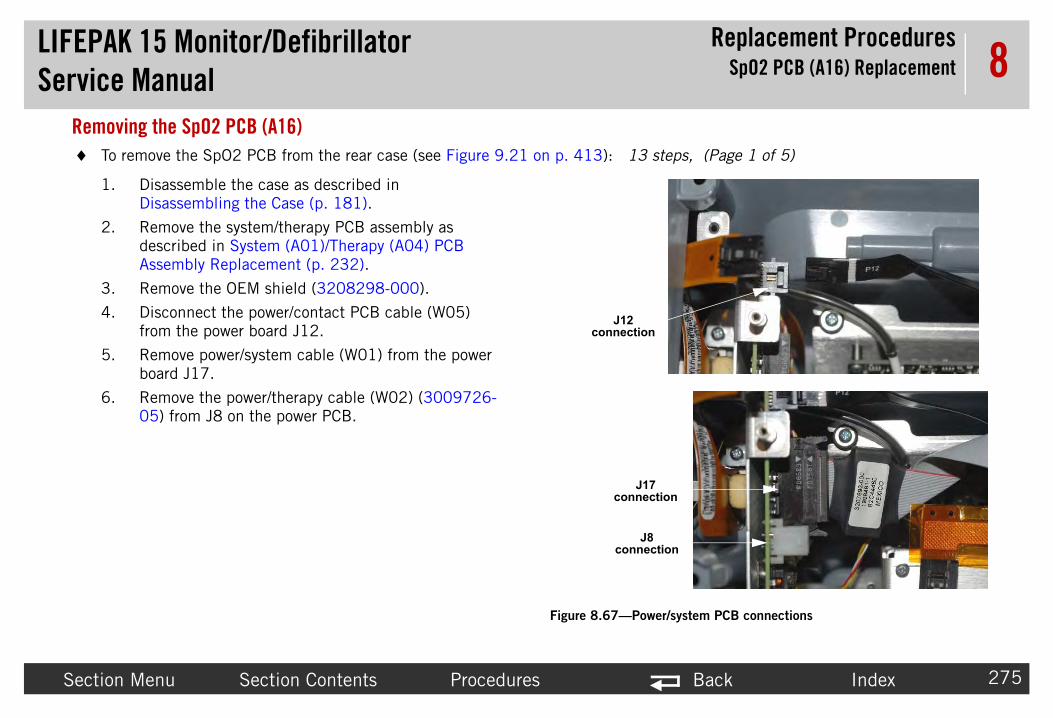
LIFEPAServic
Replacement ProceduresSpO2 PCB (A16) Replacement
Sectio Back Index 275
8Remo T eps, (Page 1 of 5)
1
2
3
4
5
6
on
on
/system PCB connections
K 15 Monitor/Defibrillatore Manual
n Menu Section Contents Procedures
ving the SpO2 PCB (A16)o remove the SpO2 PCB from the rear case (see Figure 9.21 on p. 413): 13 st
. Disassemble the case as described in Disassembling the Case (p. 181).
. Remove the system/therapy PCB assembly as described in System (A01)/Therapy (A04) PCB Assembly Replacement (p. 232).
. Remove the OEM shield (3208298-000).
. Disconnect the power/contact PCB cable (W05) from the power board J12.
. Remove power/system cable (W01) from the power board J17.
. Remove the power/therapy cable (W02) (3009726-05) from J8 on the power PCB.
J12 connection
J17 connecti
J8 connecti
Figure 8.67—Power

LIFEPAServic
Replacement ProceduresSpO2 PCB (A16) Replacement
Sectio Back Index 276
8
7
8
CAUT
POSSIflex cabconnecthe MA33054
T nued) 13 steps, (Page 2 of 5)
O2 PCB connections
K 15 Monitor/Defibrillatore Manual
n Menu Section Contents Procedures
. Disconnect the SpO2/OEM cable (W21) (3207000-004) from OEM PCB J26.
. Carefully disconnect the SpO2 connector flex cable (W22) (3206995-004) from J1 of SpO2 PCB.
ION
BLE COMPONENT DAMAGE The SpO2 connector le can be damaged during disassembly. If SpO2 tor is damaged, replace the SpO2 flex cable using SIMO Sp02 Panel Mount Cable Repair Kit (MIN 31-026) (p. 514).
o remove the SpO2 PCB from the rear case (see Figure 9.21 on p. 413): (Conti
W21 - SpO2/OEM cable
J1 connection
Figure 8.68—Sp

LIFEPAServic
Replacement ProceduresSpO2 PCB (A16) Replacement
Sectio Back Index 277
8
9
1
T nued) 13 steps, (Page 3 of 5)
screw locationsng bracket
K 15 Monitor/Defibrillatore Manual
n Menu Section Contents Procedures
. Remove the two screws (202253-764) securing the mounting bracket (3206962-001). Discard the screws.
0. Lift the SpO2 assembly (3207034-002) out of the rear case.
o remove the SpO2 PCB from the rear case (see Figure 9.21 on p. 413): (Conti
Figure 8.69—SpO2 mounti

LIFEPServic
Replacement ProceduresSpO2 PCB (A16) Replacement
Secti Back Index 278
8
1
T nued) 13 steps, (Page 4 of 5)
able w ion
2 flex cable screw
AK 15 Monitor/Defibrillatore Manual
on Menu Section Contents Procedures
1. To remove the SpO2 flex cable, remove the one screw (202253-760) attaching the SpO2/OEM flex cable (W21) (3207000-004) from the SpO2 module. Discard the screw.
o remove the SpO2 PCB from the rear case (see Figure 9.21 on p. 413): (Conti
flex cscre
locat
Figure 8.70—SpO

LIFEPAServic
Replacement ProceduresSpO2 PCB (A16) Replacement
Sectio Back Index 279
8
1
1
T nued) 13 steps, (Page 5 of 5)
screw locations
B screw locations
K 15 Monitor/Defibrillatore Manual
n Menu Section Contents Procedures
2. To remove the SpO2 module from the bracket, remove the four screws (202253-760) that attach the SpO2 module to the mounting bracket. Discard the screws.
3. Lift the SpO2 module off of the mounting bracket.
o remove the SpO2 PCB from the rear case (see Figure 9.21 on p. 413): (Conti
Figure 8.71—SpO2 PC

LIFEPServic
Replacement ProceduresSpO2 PCB (A16) Replacement
Secti Back Index 280
8InstNOT t (MIN 3305431-025) (p. 513).
eps, (Page 1 of 4)
ion
.72—SpO2 PCB connection
AK 15 Monitor/Defibrillatore Manual
on Menu Section Contents Procedures
alling the SpO2 PCB (A16)E: When installing a new SpO2 PCB, use the MASIMO Sp02 Module Repair Ki
To install the SpO2 Module in the rear case (see Figure 9.21 on p. 413): 13 st
1. Install the SpO2 module (3207034-002) on the mounting bracket.
2. Attach the SpO2 module to the bracket using four new screws (202253-760); torque to 4.0 in-lb (see Figure 8.71 on p. 279).
3. Attach the SpO2/OEM flex cable (W21) to the SpO2 module using one new screw (202253-760); torque to 4.0 in-lb.
4. Connect the SpO2 connector flex cable (W22) (3206995-004) to J1 of the SpO2 PCB.
NOTE: If installing the SpO2 connector flex cable (W22), refer to SpO2 Connector Cable (W22) Replacement (p. 344).
J1 connect
Figure 8

LIFEPAServic
Replacement ProceduresSpO2 PCB (A16) Replacement
Sectio Back Index 281
8
5
T ued) 13 steps, (Page 2 of 4)
screw locations3—SpO2 mounting bracket
K 15 Monitor/Defibrillatore Manual
n Menu Section Contents Procedures
. Install the mounting bracket (3206962-001) using two new screws (202253-764); torque to 6.8 in-lb.
o install the SpO2 Module in the rear case (see Figure 9.21 on p. 413): (Contin
Figure 8.7

LIFEPAServic
Replacement ProceduresSpO2 PCB (A16) Replacement
Sectio Back Index 282
8
6
7
T ued) 13 steps, (Page 3 of 4)
n
4—SpO2 connection to OEM PCB
n
5—Power PCB J12 connection
K 15 Monitor/Defibrillatore Manual
n Menu Section Contents Procedures
. Connect the SpO2/OEM cable (W21) (3207000-004) to the OEM PCB at J26.
. Connect the power/contact cable (W05) to the power board at J12.
o install the SpO2 Module in the rear case (see Figure 9.21 on p. 413): (Contin
J26 connectio
Figure 8.7
J12 connectio
Figure 8.7

LIFEPAServic
Replacement ProceduresSpO2 PCB (A16) Replacement
Sectio Back Index 283
8
8
9
1
1
1
1
T ued) 13 steps, (Page 4 of 4)
.76—Power/system PCB connections
f s
.77—OEM shield
eld
K 15 Monitor/Defibrillatore Manual
n Menu Section Contents Procedures
. Route CO2 adapter cable (W30) above the power/system cable as shown.
. Install power/system cable (W01) to the power board at J17.
0. Install the OEM shield (3208298-000). Route below the J8 connector and the J11 and J15 connectors.
1. Install the power/therapy cable (W02) (3009726-05) to J8 on the power PCB.
2. Install the system/therapy PCB assembly as described in System (A01)/Therapy (A04) PCB Assembly Replacement (p. 232).
3. Reassemble the case as described in Reassembling the Case (p. 184).
o install the SpO2 Module in the rear case (see Figure 9.21 on p. 413): (Contin
Figure 8
J17 connection
J8 connection
CO2 adapter cable
standoflocation
Figure 8
OEM shi

LIFEPAServic
Replacement Proceduresrconnect Bracket (A17) Replacement
Sectio Back Index 284
8InterconnInterconnect
• Re• In
K 15 Monitor/Defibrillatore Manual Inte
n Menu Section Contents Procedures
ect Bracket (A17) Replacement bracket replacement consists of the following procedures:
moving the Interconnect Bracket (A17) (p. 285)stalling the Interconnect Bracket (A17) (p. 286)
Figure 8.78—Interconnect bracket location
interconnect bracket

LIFEPAServic
Replacement Proceduresrconnect Bracket (A17) Replacement
Sectio Back Index 285
8RemoRefer
To
1.
2.
3.
4.
5.
6.
7.
capacitor bracket
wo screws
cover screw
gure 8.79—Interconnect bracket screw locations
K 15 Monitor/Defibrillatore Manual Inte
n Menu Section Contents Procedures
ving the Interconnect Bracket (A17) to Figure 8.78 on p. 284.
remove the interconnect bracket from the rear case:
Disassemble the case as described in Disassembling the Case (p. 181).
Remove the system/therapy PCB assembly as described in System (A01)/Therapy (A04) PCB Assembly Replacement (p. 232).
Remove the two mounting screws (202253-761) from the capacitor bracket and remove the bracket (3207031-001). Discard the screws.
Remove the screw (202253-761) securing the clear, plastic, high-voltage shield (3010593-00) from the interconnect bracket. Discard the screw.
Cut the cable ties that secure the interconnect bracket wiring.
Remove all spade terminals from the interconnect bracket terminals. A gripping tool may be necessary.
Cut the large tie wrap securing the interconnect bracket.
DANGER
SHOCK HAZARD Lethal voltages may be present even without operator action. Always discharge the energy storage capacitor prior to servicing. See the service manual “Capacitor Discharging Procedure (p. 178)” for detailed instructions.
t
Fi

LIFEPAServic
Replacement Proceduresrconnect Bracket (A17) Replacement
Sectio Back Index 286
8InstaRefer
To
NOTE ardware Repair Kit (MIN 3305431-015) (p.
1. ion of cable tie, add a 30 degree inward bend to the en through the rear case, then through the right hole interconnect bracket (see Figure 8.66 on p. 271).
2.
3. ergy Transfer Detail Diagram (p. 231) for cable tie
4. ct bracket with one new screw (202253-761);
5. -761); torque to 6.8 in-lb (see Figure 8.79 on p.
6. apy (A04) PCB Assembly Replacement (p. 232).
7.
K 15 Monitor/Defibrillatore Manual Inte
n Menu Section Contents Procedures
lling the Interconnect Bracket (A17) to Figure 8.78 on p. 284 and Figure 8.79 on p. 285.
install the interconnect bracket into the rear case:
: When installing a new interconnect bracket (3008897-002) use the Internal H507) and External Hardware Repair Kit (MIN 3305431-016) (p. 507).
Secure the interconnect bracket with the large cable tie. To assist in installatend of the cable tie. Feed the large tie through the left hole of the bracket, thof the bracket. Tighten so that the tie collar fits on the triangular point of theCut off excess length of the cable tie.
Figure 8.80— Large cable tie direction
Connect all spade terminals to the interconnect bracket.
Install the cable ties that secure the interconnect bracket wiring (see the Enlocations).
Secure the clear plastic high-voltage shield (3010593-00) to the interconnetorque to 6.8 in-lb (see Figure 8.79 on p. 285).
Secure the capacitor bracket (3207031-001) with two new screws (202253285).
Install the system/therapy PCB assembly as described in System (A01)/Ther
Reassemble the case as described in Reassembling the Case (p. 184)).
direction
viewed from inside of rear case

LIFEPAServic
Replacement Procedures (A21)/CO2 (A23) Module Replacement
Sectio Back Index 287
8NIBP (A21NIBP/C02 m
• Re• In
K 15 Monitor/Defibrillatore Manual NIBP
n Menu Section Contents Procedures
)/CO2 (A23) Module Replacement odule replacement consists of the following procedures:
moving the NIBP (A21)/CO2 (A23) Modules (p. 288)stalling the NIBP (A21)/CO2 (A23) Modules (p. 292)
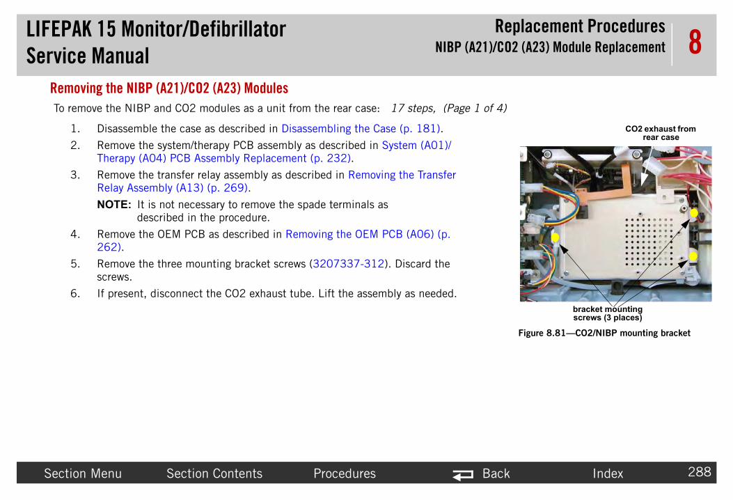
LIFEPAServic
Replacement Procedures (A21)/CO2 (A23) Module Replacement
Sectio Back Index 288
8RemoTo re e 1 of 4)
1
2
3
4
5
6bracket mounting screws (3 places)
CO2 exhaust from rear case
Figure 8.81—CO2/NIBP mounting bracket
K 15 Monitor/Defibrillatore Manual NIBP
n Menu Section Contents Procedures
ving the NIBP (A21)/CO2 (A23) Modulesmove the NIBP and CO2 modules as a unit from the rear case: 17 steps, (Pag
. Disassemble the case as described in Disassembling the Case (p. 181).
. Remove the system/therapy PCB assembly as described in System (A01)/Therapy (A04) PCB Assembly Replacement (p. 232).
. Remove the transfer relay assembly as described in Removing the Transfer Relay Assembly (A13) (p. 269).
NOTE: It is not necessary to remove the spade terminals as described in the procedure.
. Remove the OEM PCB as described in Removing the OEM PCB (A06) (p. 262).
. Remove the three mounting bracket screws (3207337-312). Discard the screws.
. If present, disconnect the CO2 exhaust tube. Lift the assembly as needed.

LIFEPAServic
Replacement Procedures (A21)/CO2 (A23) Module Replacement
Sectio Back Index 289
8
7
8
9
1
To re steps, (Page 2 of 4)
W28-W30CO2 inlet cable
connector
CO2 inlet tube
CO2 hose from module
Figure 8.82—CO2 module connections
K 15 Monitor/Defibrillatore Manual NIBP
n Menu Section Contents Procedures
. If present, disconnect the CO2 inlet tube. Lift the assembly as needed.
. If present, disconnect the CO2 cable connector inlet cable connector (W28) from CO2 adapter cable (W30).
. If present, disconnect the NIBP inlet tube. Lift the assembly as needed.
0. Lift the mounting bracket and cover from the rear case.
move the NIBP and CO2 modules as a unit from the rear case: (Continued) 17

LIFEPAServic
Replacement Procedures (A21)/CO2 (A23) Module Replacement
Sectio Back Index 290
8
1
1
1
1
To re steps, (Page 3 of 4)
cover screws (4 places)
Figure 8.83—Bracket cover screw locations
NIBP option only screws (4 places)
Figure 8.84—NIBP sub-assembly screw locations
K 15 Monitor/Defibrillatore Manual NIBP
n Menu Section Contents Procedures
1. For the NIBP option disassembly, remove the NIBP cable (W27) from cable guide on bracket cover.
2. Remove the four screws (202253-760) from the bracket cover (3206965-001) and lift off the cover. Discard the screws.
3. To remove the NIBP sub-assembly (3206268-011 or 3317965-002, remove the four screws (202253-760) and lift the assembly off the OEM bracket. Discard the screws.
4. Disconnect the OEM PCB/NIBP module cable (W27) from the A21 NIBP PCB at J2.
move the NIBP and CO2 modules as a unit from the rear case: (Continued) 17

LIFEPAServic
Replacement Procedures (A21)/CO2 (A23) Module Replacement
Sectio Back Index 291
8
1
1
1
CAUTI
POSSIB le). Scrubber material may cause caustic thoroughly with water. If scrubber materia k immediate medical attention.
To re steps, (Page 4 of 4)
CO2 option only screws (4 places)
Figure 8.85—CO2 sub-assembly screw locations
K 15 Monitor/Defibrillatore Manual NIBP
n Menu Section Contents Procedures
5. To remove the CO2 sub-assembly (3012140-006), remove the four screws (202253-760) and lift the assembly off the OEM bracket. Discard the screws.
6. Disconnect the OEM PCB/CO2 module cable from the CO2 PCB (A23) at J4.
7. Disconnect the CO2 adapter cable from the CO2 PCB (A23) at J1.
ON
LE SKIN BURNS Do not open the CO2 scrubber device (part of the CO2 moduburns. If scrubber material comes in contact with skin, rinse the area of contactl comes in contact with eyes, flush eyes with water for 15 minutes, and then see
move the NIBP and CO2 modules as a unit from the rear case: (Continued) 17

LIFEPAServic
Replacement Procedures (A21)/CO2 (A23) Module Replacement
Sectio Back Index 292
8Insta T
1
NIBP option only screws (4 places)
NIBP tube from module
Figure 8.86—NIBP module
NIBP tube inlet
NIBP tube connection
K 15 Monitor/Defibrillatore Manual NIBP
n Menu Section Contents Procedures
lling the NIBP (A21)/CO2 (A23) Moduleso install the A21 NIBP, A23 CO2, and SpO2 PCBs: 12 steps, (Page 1 of 6)
. For NIBP option:
NOTE: When replacing the NIBP module, use NIBP MAXIQ 5.2 Repair Kit (MIN 3305431-531) (p. 494) or NIBP Module Repair Kit (MIN 3305431-000) (p. 495).
a. Attach the NIBP module sub-assembly (3317965-002 or 3206268-011) to the OEM bracket (3206965-001) with four new screws (202253-760); torque to 4 in-lb.
b. Connect the OEM PCB/NIBP module cable to the A21 NIBP PCB at J2.
c. Route cable and tubing as shown and ensure that the cable and tubing are not pinched.
d. Connect the NIBP hose from the module to the inlet fitting. Route excess tubing as shown. Ensure that the NIBP tubing is routed through the hole in the bracket cover.

LIFEPAServic
Replacement Procedures (A21)/CO2 (A23) Module Replacement
Sectio Back Index 293
8
2
T e 2 of 6)
CO2 option only screws (4 places)
Figure 8.87—CO2 sub-assembly screw locations
K 15 Monitor/Defibrillatore Manual NIBP
n Menu Section Contents Procedures
. For CO2 option:
NOTE: When replacing the CO2 module, use CO2 Module Repair Kit (MIN 3305431-002) (p. 497).
a. Attach the CO2 module (3012140-006) to the mounting bracket with four new screws (202253-760); torque to 4 in-lb.
b. Connect the OEM PCB/CO2 module cable (W26) to the A23 CO2 PCB at J4.
c. Connect the CO2 adapter cable (W30) to the A23 CO2 PCB at J1.
o install the A21 NIBP, A23 CO2, and SpO2 PCBs: (Continued) 12 steps, (Pag

LIFEPAServic
Replacement Procedures (A21)/CO2 (A23) Module Replacement
Sectio Back Index 294
8
3
T e 3 of 6)
CO2 cable and tubing
CO2 cable
CO2 hose from module
Figure 8.88—CO2 tubing and cable routing
cover screws (4 places)
Figure 8.89—Bracket cover screw locations
K 15 Monitor/Defibrillatore Manual NIBP
n Menu Section Contents Procedures
d. Route the CO2 tubing and CO2 adapter cable as shown. Ensure that the cable and tubing are not pinched when installing the bracket cover.
. Attach the bracket cover to the OEM bracket with four new screws (202253-760); torque to 4.0 in-lb.
o install the A21 NIBP, A23 CO2, and SpO2 PCBs: (Continued) 12 steps, (Pag

LIFEPAServic
Replacement Procedures (A21)/CO2 (A23) Module Replacement
Sectio Back Index 295
8
4
5
T e 4 of 6)
NIBP cable mount
Figure 8.90—NIBP cable routing
bracket mounting screws (3 places)
CO2 exhaust
from rear case
Figure 8.91—CO2/NIBP mounting bracket
K 15 Monitor/Defibrillatore Manual NIBP
n Menu Section Contents Procedures
. For the NIBP option, route the NIBP cable through the cable mount on side of bracket cover.
. Place the OEM bracket into rear case and secure with the three new mounting screws (3207337-312); torque to 6.8 in-lb.
o install the A21 NIBP, A23 CO2, and SpO2 PCBs: (Continued) 12 steps, (Pag

LIFEPAServic
Replacement Procedures (A21)/CO2 (A23) Module Replacement
Sectio Back Index 296
8
6
7
T e 5 of 6)
W28-W30CO2 inlet cable
connector
CO2 inlet tube
CO2 hose from module
Figure 8.92—CO2 module connections
K 15 Monitor/Defibrillatore Manual NIBP
n Menu Section Contents Procedures
. If present, connect CO2 module tube to CO2 inlet tube.
NOTE: Older versions of the CO2 module have a Nafion inlet tube which can be pinched if pushed back into the CO2 module area. Keep the tube from the module stretched out while connecting the inlet tube.
. If present, connect CO2 inlet cable (W28) to CO2 adapter cable (W30).
o install the A21 NIBP, A23 CO2, and SpO2 PCBs: (Continued) 12 steps, (Pag

LIFEPAServic
Replacement Procedures (A21)/CO2 (A23) Module Replacement
Sectio Back Index 297
8
8
9
1
1
1
T e 6 of 6)
Figure 8.93—CO2 exhaust tube connection
K 15 Monitor/Defibrillatore Manual NIBP
n Menu Section Contents Procedures
. If present, connect the exhaust tube to the rear case outlet connector.
. Install the OEM PCB as described in Installing the OEM PCB (A06) (p. 265).
0. Install the transfer relay assembly as described in Installing the Transfer Relay Assembly (A13) (p. 270).
1. Install the system/therapy PCB assembly as described in System (A01)/Therapy (A04) PCB Assembly Replacement (p. 232).
2. Reassemble the case as described in Reassembling the Case (p. 184).
o install the A21 NIBP, A23 CO2, and SpO2 PCBs: (Continued) 12 steps, (Pag

LIFEPAServic
Replacement ProceduresInductive Resistor (A14) Replacement
Sectio Back Index 298
8Biphasic MBiphasic mo
• Re• In
K 15 Monitor/Defibrillatore Manual Biphasic Module (A22)/
n Menu Section Contents Procedures
odule (A22)/Inductive Resistor (A14) Replacement dule inductive resistor replacement consists of the following procedures:
moving the Biphasic Module (A22)/Inductive Resistor (A14) (p. 299)stalling the Biphasic Module (A22)/Inductive Resistor (A14) (p. 302)

LIFEPAServic
Replacement ProceduresInductive Resistor (A14) Replacement
Sectio Back Index 299
8Remo
T efer to Inside Rear Case Diagrams (p. 228)): 12
1
2
3
4
5
cover screw
Figure 8.94—Interconnect bracket screw locations
K 15 Monitor/Defibrillatore Manual Biphasic Module (A22)/
n Menu Section Contents Procedures
ving the Biphasic Module (A22)/Inductive Resistor (A14)
o remove the biphasic module and/or the inductive resistor from the rear case (r
steps, (Page 1 of 3)
. Disassemble the case as described in Disassembling the Case (p. 181).
. Remove the system/therapy PCB assembly as described in System (A01)/Therapy (A04) PCB Assembly Replacement (p. 232).
. Remove the screw (202253-761) securing the clear, plastic, high-voltage shield (3010593-00) to the interconnect bracket (A17). Discard the screw.
. Cut the two cable ties on the right side of the interconnect bracket.
. Disconnect the three biphasic module spade terminal connectors from the interconnect bracket (A17 - pin 3, pin 6, and pin 9). Needle nose pliers may be used to assist in disconnection.
DANGER
SHOCK HAZARD Lethal voltages may be present even without operator action. Always discharge the energy storage capacitor prior to servicing. See the service manual “Capacitor Discharging Procedure (p. 178)” for detailed instructions.

LIFEPAServic
Replacement ProceduresInductive Resistor (A14) Replacement
Sectio Back Index 300
8
6
7
8
9
1
Figure 8.95—Biphasic bracket and inductive resistor
T efer to Inside Rear Case Diagrams (p. 228)): (Con
biphasic bracket, mounting screws
with washers (2 places)
ground strap, screw with washer
J102
J108
inductive resistor
screws and washers
(2 places)
K 15 Monitor/Defibrillatore Manual Biphasic Module (A22)/
n Menu Section Contents Procedures
. Remove the two biphasic module mounting screws (3207337-312). Discard the screws.
. Lift the biphasic bracket up slightly to gain access to connector. Disconnect the red transfer relay lead spade connector from the biphasic modular assembly at J104. Needle nose pliers may be used to assist in disconnection.
. Remove the bracket (3011589-004) with the biphasic PCB (3010178-010) and inductive resistor (3010212-02) from the rear case.
. The inductive resistor (3010212-02) can be removed from the bracket prior to removing the biphasic PCB from the bracket. To remove the inductive resistor from the bracket disconnect the two spade terminal connectors at J102 and J108 of the biphasic PCB. Remove two screws (3207337-312) from the biphasic bracket, lift the mounting tabs, and lift the inductive resistor from the assembly. Discard the screws.
0. To continue removing the biphasic PCB, remove the screw (3207337-312) and ground strap (3012345-00) from the PCB. Discard the screw.
o remove the biphasic module and/or the inductive resistor from the rear case (r
tinued) 12 steps, (Page 2 of 3)

LIFEPAServic
Replacement ProceduresInductive Resistor (A14) Replacement
Sectio Back Index 301
8
1
1
T efer to Inside Rear Case Diagrams (p. 228)): (Con
K 15 Monitor/Defibrillatore Manual Biphasic Module (A22)/
n Menu Section Contents Procedures
1. Continue to remove the biphasic PCB from the bracket as follows:
a. Orient the PCB bracket as shown in the diagram (with the mounting tabs on top and one PCB mounting hole in the upper right corner).
b. Slide the PCB to the right slightly.
c. Rotate the PCB counterclockwise to clear the tab at the lower right corner.
d. Pull the PCB to the right as you lift it out.
2. Remove the remaining spade terminal wires for use on the replacement module.
o remove the biphasic module and/or the inductive resistor from the rear case (r
tinued) 12 steps, (Page 3 of 3)

LIFEPAServic
Replacement ProceduresInductive Resistor (A14) Replacement
Sectio Back Index 302
8Insta T
NOT
1
2
3
4
5
6
7
8.96—Biphasic PCB installation
J102J105
uctive resistor screws d washers (2 places)
J108
J103
J101
J104
K 15 Monitor/Defibrillatore Manual Biphasic Module (A22)/
n Menu Section Contents Procedures
lling the Biphasic Module (A22)/Inductive Resistor (A14)o install the biphasic PCB and inductive resistor: 16 steps (Page 1 of 3)
E: When replacing the Biphasic module, use Biphasic Module Repair Kit (MIN 3305431-011) (p. 504).
. Mount the biphasic PCB (3010178-010) to the biphasic bracket (3011589-004). Tilt the PCB to get into the bracket slots. (Do not bend the PCB).
. Wrap the inductive resistor (3010212-02) wires together three or four turns and connect to the biphasic PCB at J102 and J108. Ensure that the twisted wires are routed below and around CR7.
. (If removed) Clip the inductive resistor (3010212-02) into the biphasic bracket with the wires exiting away from the bracket.
. Install the wire harness (3011979-02) marked J105 to the biphasic PCB at J105.
. Install the wire harness (3011979-00) marked J103 to the biphasic PCB at J103.
. Install the wire harness (3011979-01) marked J101 to the biphasic PCB at J101.
. If inductive resistor was removed: Install two new screws with washer (3207337-312) into the bracket securing the inductive resistor in place; torque to 4.0 in-lb.
Figure
indan

LIFEPServic
Replacement Procedures/Inductive Resistor (A14) Replacement
Secti Back Index 303
8
re 8.97—Biphasic bracket mounting
of 3)
asic bracket, nting screws th washers 2 places)
ound strap, crew with washer
round strap
I shield tab
AK 15 Monitor/Defibrillatore Manual Biphasic Module (A22)
on Menu Section Contents Procedures
8. Insert one new screw with washer (3207337-312) through the ground strap (3012345-00) and install through the biphasic PCB and bracket; torque to 6.8 in-lb.
9. Place the biphasic bracket into the rear case but do not completely install. Leave the bracket up slightly for access to J104 connector. Connect the red transfer relay lead spade connector to the biphasic modular assembly at J104. Seat the biphasic bracket into the rear case.
10. Route EMI shield tab over the biphasic PCB bracket. Route ground strap over EMI shield tab.
11. Secure the biphasic PCB bracket into the rear case with two new screws with washer (3207337-312); torque to 6.8 in-lb.
Figu
To install the biphasic PCB and inductive resistor: (Continued) 16 steps (Page 2
biphmou
wi(
grs
g
EM

LIFEPAServic
Replacement ProceduresInductive Resistor (A14) Replacement
Sectio Back Index 304
8
1
8.98—High voltage shield
1
1
1
1
T of 3)
cover screw
K 15 Monitor/Defibrillatore Manual Biphasic Module (A22)/
n Menu Section Contents Procedures
2. Install two cable ties to the right side of the interconnect bracket (A17).
Figure
3. Install one new screw (202253-761) securing the clear, plastic, high-voltage shield (3010593-00) to the interconnect bracket (A17); torque to 6.8 in-lb.
4. Replace the system/therapy PCB assembly as described in System (A01)/Therapy (A04) PCB Assembly Replacement (p. 232).
5. Reassemble the case as described in Reassembling the Case (p. 184).
6. After device reassembly, complete the TCP – Defibrillator Energy Calibration procedure. The defibrillator calibration constants may be invalidated when you replace Defibrillator Energy delivery components.
o install the biphasic PCB and inductive resistor: (Continued) 16 steps (Page 3

LIFEPAServic
Replacement ProceduresEMI Shield Replacement
Sectio Back Index 305
8EMI Shield
Th ry Pins / Power PCB Cable (W10) Replacement (p. 33
To ) procedure, using the following guidelines.
1.
2.
3. e.
4. the Battery Pins/Power PCB Cable (W10) (p. 336).
EMI shield
Kep nuts (4 places)
K 15 Monitor/Defibrillatore Manual
n Menu Section Contents Procedures
Replacemente shield is supplied as part of the rear case. Follow the instructions in the Batte4) procedure to remove the EMI shield (3206960-002).
Figure 8.99—EMI shield and battery wire harness nut locations
install the EMI shield, reverse the steps in the Rear Case Replacement (p. 315
Clean with alcohol in the area where the EMI shield adhesive contacts case.
Pre-fold EMI case shield by placing the shield into the rear case.
Remove adhesive liners and secure EMI shield with Adhesive patches to cas
To complete EMI shield installation, follow the steps described in Installing
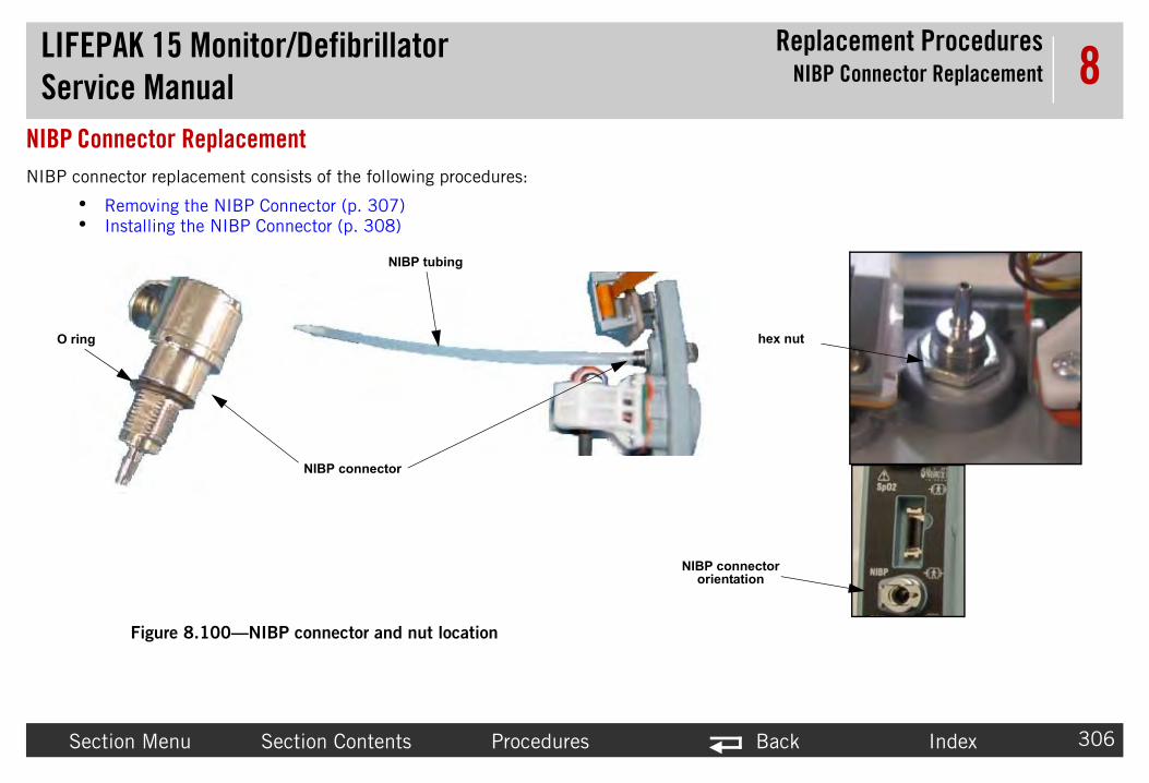
LIFEPAServic
Replacement ProceduresNIBP Connector Replacement
Sectio Back Index 306
8NIBP ConnNIBP connec
• Re• In
O ring hex nut
onnector tation
K 15 Monitor/Defibrillatore Manual
n Menu Section Contents Procedures
ector Replacement tor replacement consists of the following procedures:
moving the NIBP Connector (p. 307)stalling the NIBP Connector (p. 308)
Figure 8.100—NIBP connector and nut location
NIBP connector
NIBP tubing
NIBP corien

LIFEPAServic
Replacement ProceduresNIBP Connector Replacement
Sectio Back Index 307
8RemoRefer
To e Rear Case Diagrams (p. 228)):
NOTE me of these options.
1.
2. rapy (A04) PCB Assembly Replacement (p. 232).
3. (p. 311).
4. 001).
5. r (3207033-001).
6.
K 15 Monitor/Defibrillatore Manual
n Menu Section Contents Procedures
ving the NIBP Connector to Figure 8.100 on p. 306.
remove the NIBP connector from the parameter bezel (rear case—refer to Insid
: These steps include all parameter bezel options. Your device may not have so
Disassemble the case as described in Disassembling the Case (p. 181).
Remove the system/therapy PCB assembly as described in System (A01)/The
Remove the parameter bezel as described in Removing the Parameter Bezel
Remove the NIBP tube (3012180-02) from the NIBP connector (3207033-
Remove the fitting nut on the back side of the bezel to remove the connecto
Remove the NIBP connector from the bezel.

LIFEPAServic
Replacement ProceduresNIBP Connector Replacement
Sectio Back Index 308
8InstaRefer
To Rear Case Diagrams (p. 228)):Kit (MIN 3305431-022) (p. 510).
1. k side of the bezel. Ensure the O ring seal is on the .11 on p. 393 for NIBP connector orientation).
2. 1).
the fitting, the tube end should be trimmed
3. . 313).
4. m (A01)/Therapy (A04) PCB Assembly (p. 239).
5.
K 15 Monitor/Defibrillatore Manual
n Menu Section Contents Procedures
lling the NIBP Connector to Figure 8.100 on p. 306.
install the NIBP connector into the parameter bezel (rear case—refer to Inside NOTE: When installing a new NIBP connector, use NIBP Connector Repair
Install the connector (3207033-001) by installing the fitting nut on the bacNIBP connector (torque to 10.0 in-lb using a 1/2" deep socket) (see Figure 9
Connect the NIBP tube (3012180-02) to the NIBP connector (3207033-00
NOTE: If the NIBP tube has been previously disconnected/reconnected fromto maintain an airtight seal.
Install the parameter bezel as described in Installing the Parameter Bezel (p
Install the system/therapy PCB assembly as described in Installing the Syste
Reassemble the case as described in Reassembling the Case (p. 184).

LIFEPAServic
Replacement ProceduresParameter Bezel Replacement
Sectio Back Index 309
8ParameteParameter B
• Re• In
K 15 Monitor/Defibrillatore Manual
n Menu Section Contents Procedures
r Bezel Replacementezel replacement consists of the following procedures:
moving the Parameter Bezel (p. 311)stalling the Parameter Bezel (p. 313)

LIFEPAServic
Replacement ProceduresParameter Bezel Replacement
Sectio Back Index 310
8
screw locations (2 places)
NIBP hose routing(routed below ECG connector
brackets)
K 15 Monitor/Defibrillatore Manual
n Menu Section Contents Procedures
Figure 8.101—Parameter bezel component orientations

LIFEPAServic
Replacement ProceduresParameter Bezel Replacement
Sectio Back Index 311
8RemoRefer
NOTE l. Skip the steps pertaining to options your
NOTE acement procedure from the Summary of
K 15 Monitor/Defibrillatore Manual
n Menu Section Contents Procedures
ving the Parameter Bezel to Figure 9.10 on p. 392, Figure 9.11 on p. 393, and Figure 9.12 on p. 394.
: This procedure includes the OEM PCB and all options on the parameter bezedevice does not have.
: To remove cables from the parameter bezel, select the appropriate cable replReplacement Procedures (p. 170) (for example, SpO2 Cable).
LIFEPAServic
Replacement ProceduresParameter Bezel Replacement
Sectio Back Index 312
8 T
1
2 tem (A01)/Therapy (A04) PCB Assembly (p. 233).
3 2).
4 Figure 8.52 on p. 255).
5
6
7 dapter cable (W30).
8
9 995-004) from J1 of the SpO2 PCB.
CAUT
POSSI during disassembly. If SpO2 connector is damage pair Kit (MIN 3305431-026) (p. 514) kit.
1
1
1
1
K 15 Monitor/Defibrillatore Manual
n Menu Section Contents Procedures
o remove the parameter bezel from the rear case:
. Disassemble the case as described in Disassembling the Case (p. 181).
. Remove the system/therapy PCB assembly as described in Removing the Sys
. Remove the OEM PCB as described in Removing the OEM PCB (A06) (p. 26
. Disconnect the power/contact PCB (W05) from the power board at J12 (see
. Remove the power/system cable (W01) from the power board at J17.
. If present, disconnect the CO2 inlet tube.
. If present, carefully disconnect the CO2 cable connector (W28) from CO2 a
. If present, disconnect the NIBP tube at tube fitting.
. If present, carefully disconnect the SpO2 connector flex cable (W22) (3206
ION
BLE COMPONENT DAMAGE The SpO2 connector flex cable can be damagedd, replace the SpO2 flex cable using the MASIMO Sp02 Panel Mount Cable Re
0. If present, remove the CO2 door.
1. Remove the parameter bezel label from the bezel.
2. Remove the two bezel mounting screws (202253-763). Discard the screws.
3. Lift out the parameter bezel (3206723-005) from the rear case.

LIFEPAServic
Replacement ProceduresParameter Bezel Replacement
Sectio Back Index 313
8Insta
C
P n the p are e
T
NOT , use the External Hardware Repair Kit
Obse
• C
1 the old parameter bezel to the new parameter
eplacement (p. 328). 344)
e (W28) Replacement (p. 350)tor Assembly (W33) Replacement (p. 355)
placement (p. 357)
2 s.
K 15 Monitor/Defibrillatore Manual
n Menu Section Contents Procedures
lling the Parameter Bezel
AUTION
OSSIBLE MOISTURE LEAKAGE Visually inspect the mating surfaces betweearameter bezel and the rear case before and after fastening to ensure that they ven.
o install the parameter bezel: 15 steps, (Page 1 of 2)
E: When installing the parameter bezel (3206723-005) as a stand-alone repair(MIN 3305431-016) (p. 507).
rve the following:
lean away any adhesive residue on the parameter bezel with isopropyl alcohol.
. If you are installing a new parameter bezel, transfer the following items frombezel, as they apply to your device.
~ ECG connector cable (use a new seal)—ECG Connector Cable (W07) R~ SpO2 connector cable—SpO2 Connector Cable (W22) Replacement (p~ NIBP connector O-ring nut—NIBP Connector Replacement (p. 306)~ CO2 inlet connector cable (use a new seal)—CO2 Inlet Connector Cabl~ Invasive Pressure connector (use new seals)—Invasive Pressure Connec~ Temperature connector cable—Temperature Cable Assembly (W35) Re
. Place the parameter bezel above the rear case to make the cable connection

LIFEPAServic
Replacement ProceduresParameter Bezel Replacement
Sectio Back Index 314
8
3 racket next to the J9 connector, power PCB.nsure that it is fully seated.
4 JP1.
5 d to the CO2 module (A23).
6 cable (W30).
7 763); torque to 6.8 in-lb.
NO se standoff. NIBP hose movement
8 cess in the bezel before applying the label.
9 (see Figure 8.56 on p. 258).
1 Figure 8.58 on p. 260).
1 ).
1 rapy (A04) PCB Assembly Replacement (p. 232).
1
1 the label set (3207318-XXX) to the bezel front.
1 ter.
T
K 15 Monitor/Defibrillatore Manual
n Menu Section Contents Procedures
. If present, route NIBP tube (3012180-02) through opening in power PCB bConnect the NIBP tube to the NIBP connector fitting (3207033-001) and e
. If present, connect the SpO2 connector cable (W22) to SpO2 PCB (A16) at
. If present, connect the CO2 inlet tube (W28) to the barbed fitting connecte
. If present, connect the CO2 connector cable end (W28) to the CO2 adapter
. Reinstall the parameter bezel onto rear case with two new screws (202253-
TE: Ensure the NIBP hose isn't pinched by the ECG Brackets or rear cashould be unrestricted in bezel cavity (see Figure 8.101 on p. 310).
. Devices without CO2: Place a label spacer (3207407-000) into the CO2 re
. Connect the power/contact PCB cable (W05) to the power PCB (A03) at J12
0. Connect the power/system cable (W01) to the power PCB (A03) at J17 (see
1. Install the OEM PCB as described in Installing the OEM PCB (A06) (p. 265
2. Install the system/therapy PCB assembly as described in System (A01)/The
3. Reassemble the case as described in Reassembling the Case (p. 184).
4. Use a new parameter bezel label. Apply the parameter bezel label (#1) fromPress the label down firmly.
5. If CO2 is present, install the CO2 cover (3207407-000) onto the CO2 adap
o install the parameter bezel: (Continued) 15 steps, (Page 2 of 2)

LIFEPAServic
Replacement ProceduresRear Case Replacement
Sectio Back Index 315
8Rear CaseRear case re
• Re• In
handle cover screw
locations
handle covers removed
K 15 Monitor/Defibrillatore Manual
n Menu Section Contents Procedures
Replacementplacement consists of the following procedures:
moving the Rear Case (p. 316)stalling the Rear Case (p. 318)
Figure 8.102—Rear case replacement screw locations
paddle retainer covers (note: screws under
labels)
shoulder strap brackets
handle covers
handle cover screw
locations

LIFEPAServic
Replacement ProceduresRear Case Replacement
Sectio Back Index 316
8Remo T
1
2 erapy (A04) PCB Assembly Replacement (p. 232).
3 hield (3010593-00) from the interconnect bracket
4 t and remove the bracket (3207031-001) (see
5 ure 8.95 on p. 300). Discard the screws.
6 e capacitor and interconnect bracket to the rear lay and Biphasic module assembly without
7 2).
8 (p. 311).
9 O2 (A23) Modules (p. 288). (Removing the bracket
1 p. 275) (if installed).
1 254).
1 (p. 359).
1 ed in Removing the System Connector Cable (W08) 1) during installation).
K 15 Monitor/Defibrillatore Manual
n Menu Section Contents Procedures
ving the Rear Caseo remove the rear case: 17 steps, (Page 1 of 2)
. Disassemble the case as described in Disassembling the Case (p. 181).
. Remove the system/therapy PCB assembly as described in System (A01)/Th
. Remove the screw (202253-761) securing the clear, plastic, high-voltage s(A17) (see Figure 8.2 on p. 178). Discard the screw.
. Remove the two mounting screws (202253-761) from the capacitor brackeFigure 8.65 on p. 269). Discard the screws.
. Remove the two biphasic module mounting screws (3207337-312) (see Fig
. Observing orientation, cut the large tie wrap securing the A15 energy storagcase. Remove the energy storage capacitor, interconnect bracket, transfer reremoving small cable ties and spade terminal connections.
. Remove the OEM PCB as described in Removing the OEM PCB (A06) (p. 26
. Remove the parameter bezel as described in Removing the Parameter Bezel
. Remove the NIBP/CO2 module as described in Removing the NIBP (A21)/Ccover in this procedure is not required.)
0. Remove the SpO2 module as described in Removing the SpO2 PCB (A16) (
1. Remove the power PCB as described in Removing the Power PCB (A03) (p.
2. Remove the contact PCB as described in Removing the Contact PCB (A07)
3. Remove the system connector cable and auxiliary connector cable as describor Auxiliary Power Cable (W09) (p. 332) (use new O-ring seals (200060-01

LIFEPAServic
Replacement ProceduresRear Case Replacement
Sectio Back Index 317
8
1 he rear case by removing the four Kep nuts
1
1 lex Module (p. 339)
1
T
K 15 Monitor/Defibrillatore Manual
n Menu Section Contents Procedures
4. Disconnect the battery pins/power PCB cable (W10) (3207692-000) from t(201508-000) (see Figure 8.99 on p. 305). Reuse the Kep nuts.
5. Remove the CO2 exhaust (3012140-002) from the rear case (if installed).
6. Remove the USB flex assembly as described in Removing the W14 - USB F
~ Remove the drain seal (3006291-00) from the rear case.
7. Remove the handle as described in Removing the Handle (p. 321).
o remove the rear case: (Continued) 17 steps, (Page 2 of 2)

LIFEPAServic
Replacement ProceduresRear Case Replacement
Sectio Back Index 318
8Insta T
• W . 512).• C
Trans
1 bed in Handle Replacement (p. 321).
020) (p. 509).
2
3 n).
4 . 359).
5 Installing the System Connector Cable (W08) or ).
6 ent (p. 305) (new part from repair kit).
7 d in Installing the Battery Pins/Power PCB Cable
8 contact PCB.
9 acement (p. 338).
K 15 Monitor/Defibrillatore Manual
n Menu Section Contents Procedures
lling the Rear Caseo install the rear case: 23 steps, (Page 1 of 3)
hen replacing the Rear Case, use Rear Case Repair Kit (MIN 3305431-024) (plean adhesive areas with alcohol.
fer the following parts from the old rear case to the new rear case:
. Install handle (3207706-000), handle covers and shoulder straps as descri
NOTE: If a new handle is required, use Handle Repair Kit (MIN 3305431-
. Install the drain seal (3006291-00) into the rear case.
. Install the CO2 exhaust tubing (3012140-002) onto rear case (if CO2 optio
. Install the contact PCB as described in Installing the Contact PCB (A07) (p
. Install the system connector and auxiliary connector cables as described in Auxiliary Power Cable (W09) (p. 333) using new O-ring seals (200060-011
. Install the EMI shield (3206960-002) as described in EMI Shield Replacem
. Install the battery pins/power PCB cable (W10) (3207692-000) as describe(W10) (p. 336).
. Install the power to contact PCB cable (W05) (3207261-001) to J42 of the
. Install the USB flex assembly as described in USB Flex Module (W14) Repl

LIFEPAServic
Replacement ProceduresRear Case Replacement
Sectio Back Index 319
8
1 new part from repair kit).
1 e using a large cable tie (200536-001). Place the
1
her in the reassembly process.
1 2)/Inductive Resistor (A14) (p. 302).
1 . 313).
1 7).
1 pO2 PCB (A16) (p. 280).
1 21)/CO2 (A23) Modules (p. 292).
1 lay Assembly (A13) (p. 270).
1 ).
2 rapy (A04) PCB Assembly Replacement (p. 232).
2
T
K 15 Monitor/Defibrillatore Manual
n Menu Section Contents Procedures
0. Install four battery pins as described in Battery Pin Replacement (p. 364) (
1. Secure the energy storage capacitor and interconnect bracket to the rear casbottom of energy storage capacitor flush to the rear case.
2. Route the energy storage capacitor wires along left side of capacitor body.
NOTE: Place transfer relay on top of the energy storage capacitor until furt
3. Install the biphasic PCB as described in Installing the Biphasic Module (A2
4. Install the parameter bezel as described in Installing the Parameter Bezel (p
5. Install the power PCB as described in Installing the Power PCB (A03) (p. 25
6. If option is present, install the SpO2 module as described in Installing the S
7. Install the NIBP/CO2 Module housing as described in Installing the NIBP (A
8. Install the transfer relay assembly as described in Installing the Transfer Re
9. Install the OEM PCB as described in Installing the OEM PCB (A06) (p. 265
0. Install the system/therapy PCB assembly as described in System (A01)/The
1. Reassemble the case as described in Reassembling the Case (p. 184).
o install the rear case: (Continued) 23 steps, (Page 2 of 3)

LIFEPAServic
Replacement ProceduresRear Case Replacement
Sectio Back Index 320
8
2 tion is present).
2
-Control technical services)
T
K 15 Monitor/Defibrillatore Manual
n Menu Section Contents Procedures
2. Install the SpO2 patent label (3207359-000) in battery well 2 (if SpO2 op
3. When installing the rear case, install the following NEW labels:
~ Battery well 2 cover label, see label set (3207318-XXX), label # 9~ Battery well 1 cover label, see label set (3207318-XXX), label # 8~ Bluetooth label, see label set (3207318-XXX), label # 12~ Capacitor mount cover label, see label set (3207318-XXX), label # 2~ CO2 cover label, see label set (3207318-XXX), label # 7~ Sys/Aux connector label, see label set (3207318-XXX), label # 3~ FDA label, see label set (3207318-XXX), label # 5 ~ Serial number label (3207131) (special order required, contact Physio
o install the rear case: (Continued) 23 steps, (Page 3 of 3)

LIFEPAServic
Replacement ProceduresHandle Replacement
Sectio Back Index 321
8Handle ReHandle repla
• Re• In
Remo To
1.
2.
3.
4.
Insta To
1.
2.
3.
handle cover screw
locations(4 places)
dle covers emoved
re 8.103—Handle replacement
K 15 Monitor/Defibrillatore Manual
n Menu Section Contents Procedures
placementcement consists of the following procedures:
moving the Handle (p. 321)stalling the Handle (p. 321)
ving the Handle remove the handle:
Remove the four screws (201407-069) for each handle cover. Discard the screws.
Remove the left and right shoulder strap brackets (3207708-000).
Remove the left (3207707-000) and right (3207746-000) handle covers.
Remove the handle (3207706-000).
lling the Handle install the handle:
Place the handle (3207706-000) in the slots of the case. (Note that the front side of the handle has the triangular indentation.)
Attach the left (3207707-000) and right (3207746-000) handle covers to the rear case using six new screws (201407-069); torque to 10 in-lb using a P2 bit.
Install the shoulder strap brackets (3207708-000) using two new screws (201407-069); torque to 10 in-lb using a P2 bit.
handle cover screw
locations(4 places)
shoulder strap
brackets
hanr
Figu

LIFEPAServic
Replacement ProceduresPaddle Retainer Cover Replacement
Sectio Back Index 322
8Paddle RePaddle retainprocedures:
• Re• In
Remo To
1.
2.
3.
Insta To
NOTE IN 3305431-017) (p. 508).
1. ; torque to 10 in-lb using a P2 bit.
2.
rear case.
le retainer cover locations
K 15 Monitor/Defibrillatore Manual
n Menu Section Contents Procedures
tainer Cover Replacementer cover replacement consists of the following
moving the Paddle Retainer Covers (p. 322)stalling the Paddle Retainer Covers (p. 322)
ving the Paddle Retainer Covers remove the paddle retainer covers (3006766-003):
Remove the two labels (number 1 and number 2) from the covers.
Remove the six screws (201407-069) (three on each of the left and right covers). Discard the screws.
Remove the left and right retainer covers (3006766-003).
lling the Paddle Retainer Covers install the paddle retainer covers (3006766-003):
: When installing the paddle retainer covers, use Paddle Retainer Repair Kit (M
Install the left and right retainer covers using six new screws (201407-069)
Apply the new cover labels (#8 and #9) from the label set (3207318-XXX).
NOTE: Label #8 (displaying the number 1) goes to the right as you view the
paddle retainer covers (note: screws
under labels)
Figure 8.104—Padd
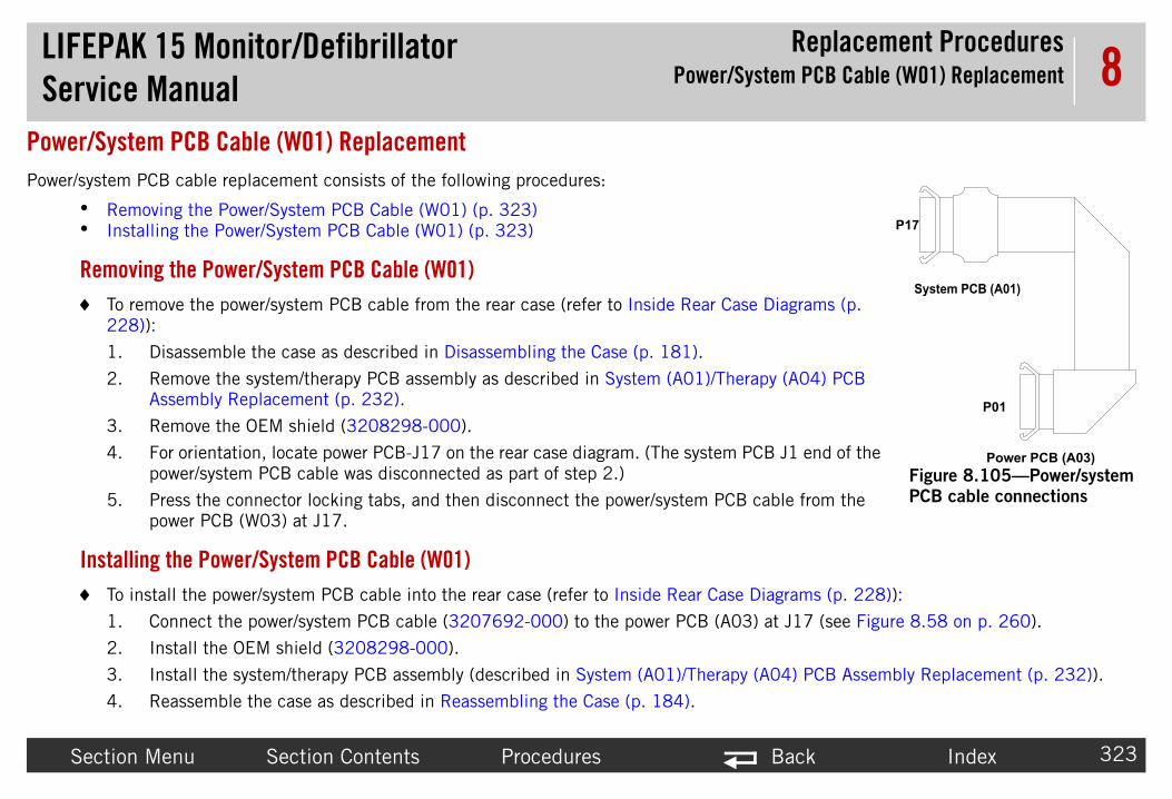
LIFEPAServic
Replacement Proceduresystem PCB Cable (W01) Replacement
Sectio Back Index 323
8Power/SysPower/system
• Re• In
Remo To se Diagrams (p.
22
1.
2. rapy (A04) PCB
3.
4. PCB J1 end of the
5. cable from the
Insta To Diagrams (p. 228)):
1. 3) at J17 (see Figure 8.58 on p. 260).
2.
3. y (A04) PCB Assembly Replacement (p. 232)).
4.
P01
P17
Power PCB (A03)
System PCB (A01)
Figure 8.105—Power/system
PCB cable connections
K 15 Monitor/Defibrillatore Manual Power/S
n Menu Section Contents Procedures
tem PCB Cable (W01) Replacement PCB cable replacement consists of the following procedures:
moving the Power/System PCB Cable (W01) (p. 323)stalling the Power/System PCB Cable (W01) (p. 323)
ving the Power/System PCB Cable (W01) remove the power/system PCB cable from the rear case (refer to Inside Rear Ca8)):
Disassemble the case as described in Disassembling the Case (p. 181).
Remove the system/therapy PCB assembly as described in System (A01)/TheAssembly Replacement (p. 232).
Remove the OEM shield (3208298-000).
For orientation, locate power PCB-J17 on the rear case diagram. (The system power/system PCB cable was disconnected as part of step 2.)
Press the connector locking tabs, and then disconnect the power/system PCBpower PCB (W03) at J17.
lling the Power/System PCB Cable (W01) install the power/system PCB cable into the rear case (refer to Inside Rear Case
Connect the power/system PCB cable (3207692-000) to the power PCB (A0
Install the OEM shield (3208298-000).
Install the system/therapy PCB assembly (described in System (A01)/Therap
Reassemble the case as described in Reassembling the Case (p. 184).

LIFEPAServic
Replacement Procedureserapy PCB Cable (W02) Replacement
Sectio Back Index 324
8Power/ThePower/System
• Re• In
K 15 Monitor/Defibrillatore Manual Power/Th
n Menu Section Contents Procedures
rapy PCB Cable (W02) Replacement PCB cable replacement consists of the following procedures:
moving the Power/Therapy PCB Cable (W02) (p. 325)stalling the Power/Therapy PCB Cable (W02) (p. 325)

LIFEPAServic
Replacement Procedureserapy PCB Cable (W02) Replacement
Sectio Back Index 325
8Remo To
1.
2. rapy (A04)
3. PCB-J20 end
4. cable at J8.
Insta To
1. ) at J8.
2. m (A01)/
3.
P08
P20
to Power PCB (A03)
to A04 Therapy PCB
Figure 8.106—Power/therapy PCB
cable connections
K 15 Monitor/Defibrillatore Manual Power/Th
n Menu Section Contents Procedures
ving the Power/Therapy PCB Cable (W02) remove the power/therapy PCB cable from the rear case:
Disassemble the case as described in Disassembling the Case (p. 181).
Remove the system/therapy PCB assembly as described in System (A01)/ThePCB Assembly Replacement (p. 232).
For orientation, locate power PCB-J8 on the rear case diagram. (The therapyof the power/therapy PCB cable was disconnected as part of step 2.)
Press the connector locking tab, and then disconnect the power/therapy PCB
lling the Power/Therapy PCB Cable (W02) install the power/therapy PCB cable into the rear case:
Connect the power/therapy PCB cable (3009726-01) to the power PCB (A03
Install the system/therapy PCB assembly as described in Installing the SysteTherapy (A04) PCB Assembly (p. 239).
Reassemble the case as described in Reassembling the Case (p. 184).

LIFEPAServic
Replacement Proceduresontact PCB Cable (W05) Replacement
Sectio Back Index 326
8Power/ConPower/conta
• Re• In
Remo To
ca
1.
2.
3.
4.
5.
6.
7.
8.
P42
P12Power PCB (A03)
A07 Contact PCB
Figure 8.107—Power/contact PCB
cable connections
K 15 Monitor/Defibrillatore Manual Power/C
n Menu Section Contents Procedures
tact PCB Cable (W05) Replacementct PCB cable replacement consists of the following procedures:
moving the Power/Contact PCB Cable (W05) (p. 326)stalling the Power/Contact PCB Cable (W05) (p. 327)
ving the Power/Contact PCB Cable (W05) remove the power/contact PCB cable (3207261-001) from the rear se:
Disassemble the case as described in Disassembling the Case (p. 181).
Remove the system/therapy PCB assembly as described in System (A01)/Therapy (A04) PCB Assembly Replacement (p. 232).
Disconnect the power/contact PCB cable from the power PCB at J12 (may be labeled P12).
Remove the transfer relay as described in Removing the Transfer Relay Assembly (A13) (p. 269).
NOTE: It is not necessary to remove the spade terminals as described in the procedure.
Remove the OEM PCB as described in Removing the OEM PCB (A06) (p. 262).
Remove the NIBP/CO2 assembly as described in Removing the NIBP (A21)/CO2 (A23) Modules (p. 288).
Disconnect the power/contact PCB cable at J42 of the contact PCB (A07).
Remove the power/contact cable.

LIFEPAServic
Replacement Proceduresontact PCB Cable (W05) Replacement
Sectio Back Index 327
8Insta To
1. B (A07).
2. 2 (A23) Modules (p. 292).
3. .
4. ay Assembly (A13) (p. 270).
5. e labeled P12).
6. m (A01)/Therapy (A04) PCB Assembly (p. 239).
7.
K 15 Monitor/Defibrillatore Manual Power/C
n Menu Section Contents Procedures
lling the Power/Contact PCB Cable (W05) install the power/contact PCB cable:
Connect the power/contact PCB cable (3207261-001) to J42 of contact PC
Install the NIBP/CO2 assembly as described in Installing the NIBP (A21)/CO
Install the OEM PCB as described in Installing the OEM PCB (A06) (p. 265)
Install the transfer relay assembly as described in Installing the Transfer Rel
Connect the power/contact PCB cable to the power PCB (A03) at J12 (may b
Install the system/therapy PCB assembly as described in Installing the Syste
Reassemble the case as described in Reassembling the Case (p. 184).

LIFEPAServic
Replacement Proceduresonnector Cable (W07) Replacement
Sectio Back Index 328
8ECG ConneECG connec
• Re• In
screlocatio
bra
s
able
K 15 Monitor/Defibrillatore Manual ECG C
n Menu Section Contents Procedures
ctor Cable (W07) Replacementtor cable replacement consists of the following procedures:
moving the ECG Connector Cable (W07) (p. 329)stalling the ECG Connector Cable (W07) (p. 330)
Figure 8.108—ECG cable part and screw locations
w ns
cket
eal
ECG c

LIFEPAServic
Replacement Procedures Connector Cable (W07) Replacement
Sectio Back Index 329
8RemoRefer
To nside Rear Case Diagrams (p. 228)):1.
2.
3. (p. 311).
4. 80-001) that holds the ECG connector cable nd screws.
K 15 Monitor/Defibrillatore Manual ECG
n Menu Section Contents Procedures
ving the ECG Connector Cable (W07) to Figure 8.108 on p. 328.
remove the ECG connector cable (3007991-007) from the rear case (refer to I
Disassemble the case as described in Disassembling the Case (p. 181).
Disconnect the ECG cable from the J6 connector on the system PCB (A01).
Remove the parameter bezel as described in Removing the Parameter Bezel
Remove the four screws (202253-763) securing the support bracket (32056(3007991-007). Remove the connector, seal and screws. Discard the seal a

LIFEPAServic
Replacement Procedures Connector Cable (W07) Replacement
Sectio Back Index 330
8InstaRefer
To agrams (p. 228)): (MIN 3305431-010) (p. 503).
1. 05915-01). Orient the ECG receptacle groove to the
2. -001) and line up the ECG receptacle.
3. l with the four new screws (202253-763); torque to
4. . 313).
5. CB (A01).
6.
C
P se a n
K 15 Monitor/Defibrillatore Manual ECG
n Menu Section Contents Procedures
lling the ECG Connector Cable (W07) to Figure 8.108 on p. 328.
install the ECG connector cable into the rear case (refer to Inside Rear Case Di
NOTE: When installing a new ECG cable, use the ECG Connector Repair Kit
Mount the ECG receptacle contact cable (3007991-007) on the ECG seal (8notch in the seal.
Capture the cable ferrite between the two cable support brackets (3205680
Secure the ECG connector cable and support brackets to the parameter beze6.8 in-lb.
Install the parameter bezel as described in Installing the Parameter Bezel (p
Connect the ECG cable (3007991-007) to the J6 connector on the system P
Reassemble the case as described in Reassembling the Case (p. 184).
AUTION
OSSIBLE MOISTURE LEAKAGE When installing the ECG connector cable, uew seal (805915-01) to help prevent ingress of fluids.

LIFEPAServic
Replacement Procedures (W08) and Auxiliary Connector Cable
(W09) Replacement
Sectio Back Index 331
8System Co cementThe system c dures:
• Re 332)• In 33)
parts
seal plates and nuts
K 15 Monitor/Defibrillatore Manual System Connector Cable
n Menu Section Contents Procedures
nnector Cable (W08) and Auxiliary Connector Cable (W09) Replaonnector and auxiliary power cable replacement consists of the following proce
moving the System Connector Cable (W08) or Auxiliary Power Cable (W09) (p. stalling the System Connector Cable (W08) or Auxiliary Power Cable (W09) (p. 3
Figure 8.109—System connector cable and auxiliary power cable location and
system connector
O ringsauxiliary power

LIFEPAServic
Replacement Procedures (W08) and Auxiliary Connector Cable
(W09) Replacement
Sectio Back Index 332
8RemoRefer
To part 3303848-002), from the rear case:
1.
2. (p. 311).
3. 54).
4. seal (805487-00), and O-ring seal (200060-011).
5. al (805487-00), and O-ring seal (200060-011).
K 15 Monitor/Defibrillatore Manual System Connector Cable
n Menu Section Contents Procedures
ving the System Connector Cable (W08) or Auxiliary Power Cable (W09) to Figure 8.109 on p. 331.
remove the system connector cable (3009652-01) or auxiliary power cable (V2
Disassemble the case as described in Disassembling the Case (p. 181).
Remove the parameter bezel as described in Removing the Parameter Bezel
Remove the power PCB as described in Removing the Power PCB (A03) (p. 2
If required, remove the system connector cable nut (806091-00), connectorRemove the System connector cable.
If required, remove the auxiliary power cable nut (806091-00), connector seRemove the connector.

LIFEPAServic
Replacement Procedures (W08) and Auxiliary Connector Cable
(W09) Replacement
Sectio Back Index 333
8InstaRefer
To
NOTE er cable (V2 part 3303848-002), use the dware Repair Kit (MIN 3305431-016) (p.
1. wer cable connector.
2. le.
3. ire connector of the system cable (torque to 10 in-lb
4. se.
5. wer cable.
6. ire connector of the auxiliary power cable (torque to
7. 7).
8. . 313).
9. m (A01)/Therapy (A04) PCB Assembly (p. 239).
10
C
P use a n
K 15 Monitor/Defibrillatore Manual System Connector Cable
n Menu Section Contents Procedures
lling the System Connector Cable (W08) or Auxiliary Power Cable (W09) to Figure 8.109 on p. 331.
install the system connector cable or auxiliary power cable into the rear case:
: When installing a new system connector cable (3009652-01) or auxiliary powInternal Hardware Repair Kit (MIN 3305431-015) (p. 507) and External Har507).
If removed, install the system connector cable in hole above the auxiliary po
Thread the new O-ring (200060-011) over wire connector of the system cab
Thread seal plate (805487-00) (flat side down) and nut (806091-00) over wusing a 3/4” modified deep socket).
If removed, install auxiliary power cable in the lower hole provided in rear ca
Thread the new O-ring (200060-011) over wire connector of the auxiliary po
Thread seal plate (805487-00) (flat side down) and nut (806091-00) over w10 in-lb using a 3/4” modified deep socket).
Install the power PCB as described in Installing the Power PCB (A03) (p. 25
Install the parameter bezel as described in Installing the Parameter Bezel (p
Install the system/therapy PCB assembly as described in Installing the Syste
. Reassemble the case as described in Reassembling the Case (p. 184).
AUTION
OSSIBLE MOISTURE LEAKAGE When installing the system connector cable,ew O-ring seal to help prevent ingress of fluids.

LIFEPAService
Replacement Proceduresower PCB Cable (W10) Replacement
Secti Index 334
8Battery Pin
• Re• Ins
K 15 Monitor/Defibrillator Manual Battery Pins / P
on Menu Section Contents Back
s / Power PCB Cable (W10) Replacement moving the Battery Pins/Power PCB Cable (W10) (p. 335)talling the Battery Pins/Power PCB Cable (W10) (p. 336)
Figure 8.110—Power PCB cable Kep nut and cable locations
Kep nut and cablelocations

LIFEPAService
Replacement Proceduresower PCB Cable (W10) Replacement
Secti Index 335
8RemoRefer
To 9.17 on p. 403):
1.
2. )/Therapy (A04) PCB Assembly (p. 233).
3. lay Assembly (A13) (p. 269). (It is not necessary to
4. the Biphasic Module (A22)/Inductive Resistor ed in the procedure.)
5. capacitor and interconnect bracket to the rear case. r and interconnect bracket without removing small
6. ).
7. 54).
8. O2 (A23) Modules (p. 288). (Removing the bracket
9. 44 at battery well 1, and P45 and P46 at battery installing the wires to the same studs. Remove the
10 d. Clean the rear case of residual adhesive.
K 15 Monitor/Defibrillator Manual Battery Pins / P
on Menu Section Contents Back
ving the Battery Pins/Power PCB Cable (W10)to Figure 8.110 on p. 334 and Figure 8.99 on p. 305.
remove the Battery Pins/Power PCB Cable (W10) from the rear case (see Figure
Disassemble the case as described in Disassembling the Case (p. 181).
Remove the system/therapy board as described in Removing the System (A01
Remove the transfer relay assembly as described in Removing the Transfer Reremove the spade terminals as described in the procedure.)
Remove the biphasic module and inductive resistor as described in Removing(A14) (p. 299). (It is not necessary to remove the spade terminals as describ
Observing orientation, cut the large tie wrap securing the A15 energy storage Remove the transfer relay, biphasic module assembly, energy storage capacitocable ties and spade terminal connections.
Remove the OEM PCB as described in Removing the OEM PCB (A06) (p. 262
Remove the power PCB as described in Removing the Power PCB (A03) (p. 2
Remove the NIBP/CO2 assembly as described in Removing the NIBP (A21)/Ccover in this procedure is not required.)
Remove the four Kep nuts (201508-000) to disconnect terminals P43 and Pwell 2 (see Figure 8.99 on p. 305). Note the wire colors and orientation for recable.
. If replacing the EMI shield, lift the EMI shield out of the rear case and discar

LIFEPAService
Replacement Proceduresower PCB Cable (W10) Replacement
Secti Index 336
8Instal
To install
If req
1. 03863-000).
2. ery Well 2 and ket and drive
3. 7).
4. 16) (p. 280).
5. he power PCB
6. (A23) Modules
7. .
8. rage Capacitor
9. the Biphasic
10 ay Assembly
P11 P13
P46
P45
P44
P43
to Power PCB (A03)
to Battery Well 1
to Battery Well 2
Figure 8.111—(V1) Power
PCB cable connections. V2
cable, only P11 is used.
K 15 Monitor/Defibrillator Manual Battery Pins / P
on Menu Section Contents Back
ling the Battery Pins/Power PCB Cable (W10)
the W10 cable: 12 steps, (Page 1 of 2)
uired, replace EMI shield as described in EMI Shield Replacement (p. 305).
Install the battery pins/power PCB (W10) cable (V1- 3009726-08) or (V2-33
Connect terminals P43 and P44 at Battery Well 1, and P45 and P46 at Battreplace the four Kep nuts (201508-000) (torque to 4.0 in-lb using 1/4” socadapter). See Figure 8.110 on p. 334.
Install the power PCB as described in Installing the Power PCB (A03) (p. 25
If present, install the SpO2 PCB as described in Installing the SpO2 PCB (A
Connect the battery pins/power PCB cable (W10) connector locking tabs to tat J11. V1 device will also install W10 at J13.
Install the NIBP/CO2 Module as described in Installing the NIBP (A21)/CO2 (p. 292).
Install the OEM PCB as described in Installing the OEM PCB (A06) (p. 265)
Install the energy storage capacitor as described in Installing the Energy Sto(A15) (p. 273).
Install the biphasic module and inductive resistor as described in Installing Module (A22)/Inductive Resistor (A14) (p. 302).
. Install the transfer relay assembly as described in Installing the Transfer Rel(A13) (p. 270).

LIFEPAService
Replacement Proceduresower PCB Cable (W10) Replacement
Secti Index 337
8
11 he System
12
To install
K 15 Monitor/Defibrillator Manual Battery Pins / P
on Menu Section Contents Back
. Install the system/memory/therapy PCB assembly as described in Installing t(A01)/Therapy (A04) PCB Assembly (p. 239).
. Reassemble the case as described in Reassembling the Case (p. 184).
the W10 cable: (Continued) 12 steps, (Page 2 of 2)

LIFEPAService
Replacement ProceduresUSB Flex Module (W14) Replacement
Secti Index 338
8USB Flex MUSB flex mod
• Re• Ins
8.112—USB flex module
USB module
K 15 Monitor/Defibrillator Manual
on Menu Section Contents Back
odule (W14) Replacementule replacement consists of the following procedures:
moving the W14 - USB Flex Module (p. 339)talling the W14 - USB Flex Module (p. 339)
Figure
LIFEPAService
Replacement ProceduresUSB Flex Module (W14) Replacement
Secti Index 339
8Remo To
1.
2. )/Therapy (A04) PCB Assembly (p. 233).
3. p. 311).
4. g clip (3012693-00). Remove the spring clip.
5. the USB access door (3206959-001).
6. screws.
7.
InstalTo inst
1. case.
2. rque to 6.8 in-lb.
3. USB flex module; torque to 6.8 in-lb.
4. crews; torque to 6.8 in-lb.
5. 313).
6. (A01)/Therapy (A04) PCB Assembly (p. 239).
7.
K 15 Monitor/Defibrillator Manual
on Menu Section Contents Back
ving the W14 - USB Flex Moduleremove the USB flex module (W14) (3206966-001):
Disassemble the case as described in Disassembling the Case (p. 181).
Remove the system/therapy board as described in Removing the System (A01
Remove the parameter bezel as described in Removing the Parameter Bezel (
From inside the rear case, remove the screw (202253-761) holding the sprinDiscard the screw.
From the outside rear of the case, loosen the two retained screws and remove
Remove the two USB connector mounting screws (202253-761). Discard the
Remove the USB flex assembly.
ling the W14 - USB Flex Moduleall the USB flex module (W14) (3206966-001):
From inside of the rear case, place the USB flex module into slot in the rear
Install the spring clip (3012693-00) using one new screw (202253-761); to
From the outside of the rear case, install two screws (202253-761) into the
Install the USB access door (3206959-001) by tightening the two retained s
Install the parameter bezel as described in Installing the Parameter Bezel (p.
Install the system/therapy PCB assembly as described in Installing the System
Reassemble the case as described in Reassembling the Case (p. 184).

LIFEPAService
Replacement ProceduresBiphasic Cable (W20) Replacement
Secti Index 340
8Biphasic CBiphasic cab
• Re• Ins
8.113— Biphasic cables
to A01 System PCBrapy PCB
51
P106
P10
to A22 Biphasic PCB
on 3206999 cable is no longer orderable
K 15 Monitor/Defibrillator Manual
on Menu Section Contents Back
able (W20) Replacement le replacement consists of the following procedures:
moving the Biphasic Cable (W20) (p. 341)talling the Biphasic Cable (W20) (p. 341)
Figure
to A04 The
P
Current version of Biphasic cable 3011792-005
Previous versi

LIFEPAService
Replacement ProceduresBiphasic Cable (W20) Replacement
Secti Index 341
8Remo To
1.
2. sic PCB at J106.
3. t the W20 cable from the A01 system PCB at J10.
4. y PCB at J51.
Instal To
1.
2. m PCB at J10.
3.
4.
K 15 Monitor/Defibrillator Manual
on Menu Section Contents Back
ving the Biphasic Cable (W20)remove the biphasic cable (W20) from the rear case:
Disassemble the case as described in Disassembling the Case (p. 181).
Press the connector locking tab and eject the W20 cable from the A22 bipha
For biphasic cable (3206999) only, press the connector locking tab and ejec
Press the connector locking tab and eject the W20 cable from the A04 therap
ling the Biphasic Cable (W20)install the biphasic cable (W20) into the rear case:
Connect the W20 cable to the A04 Therapy PCB at J51.
For biphasic cable (6206999) only, connect the W20 cable to the A01 Syste
Connect the W20 cable to the A22 biphasic PCB at J106.
Reassemble the case as described in Reassembling the Case (p. 184).

LIFEPAService
Replacement ProceduresO2 (W21) Module Cable Replacement
Secti Index 342
8OEM PCB/SOEM PCB/Sp
• Re• Ins
K 15 Monitor/Defibrillator Manual OEM PCB/Sp
on Menu Section Contents Back
pO2 (W21) Module Cable ReplacementO2 Module cable replacement consists of the following procedures:
moving the OEM PCB/SpO2 Module Cable (W21) (p. 343)talling the OEM PCB/SpO2 Module Cable (W21) (p. 343)
Figure 8.114—OEM/SpO2 cable screw location
screw location
OEM/SpO2 Cable

LIFEPAService
Replacement ProceduresO2 (W21) Module Cable Replacement
Secti Index 343
8Remo To
1.
2. rapy (A04) PCB Assembly Replacement (p. 232).
3. 16) (p. 275). Do not remove SpO2 connector flex
4. scard the screw (202253-760) holding the W21
5. SpO2 module will still be connected to the system
Instal To
1.
2. able to the J3 connector; torque to 4.0 in-lb.
3. ) (p. 280).
4. py (A04) PCB Assembly Replacement (p. 232).
5.
K 15 Monitor/Defibrillator Manual OEM PCB/Sp
on Menu Section Contents Back
ving the OEM PCB/SpO2 Module Cable (W21)remove the OEM PCB/SpO2 cable (3207000-004) from the rear case:
Disassemble the case as described in Disassembling the Case (p. 181).
Remove the system/therapy PCB assembly as described in System (A01)/The
Remove the SpO2 module (A26) as described in Removing the SpO2 PCB (Acable (W22) as described in step 8 of that procedure.
Lift SpO2 assembly from rear enough to gain access to screw. Remove and dicable to the J3 connector.
Disconnect the OEM PCB/SpO2 cable from the SpO2 module (A16) at J3. Theby the SpO2 connector flex cable.
ling the OEM PCB/SpO2 Module Cable (W21)install the OEM PCB/SpO2 cable (3207000-004):
Connect the OEM PCB/SpO2 cable to the SpO2 Module (A16) at J3.
Install one new screw (202253-760) on the SpO2 module holding the W21 c
Install the SpO2 module (A16) as described in Installing the SpO2 PCB (A16
Install the system/therapy PCB assembly as described in System (A01)/Thera
Reassemble the case as described in Reassembling the Case (p. 184).

LIFEPAService
Replacement ProceduresConnector Cable (W22) Replacement
Secti Index 344
8SpO2 ConnSpO2 connec
• Re• Ins
8.115—SpO2 connector cable
K 15 Monitor/Defibrillator Manual SpO2
on Menu Section Contents Back
ector Cable (W22) Replacementtor cable replacement consists of the following procedures:
moving the SpO2 Connector Cable (W22) (p. 345)talling the SpO2 Connector Cable (W22) (p. 345)
Figure
SpO2 connectororientation

LIFEPAService
Replacement ProceduresConnector Cable (W22) Replacement
Secti Index 345
8Remo To side Rear Case Diagrams (p. 228) and Figure 9.21
on
1.
2. rapy (A04) PCB Assembly Replacement (p. 232).
3. p. 311).
4. ferrite housing (3207009-000) and SpO2
5.
Instal To side Rear Case Diagrams (p. 228)):NOTE r Kit (MIN 3305431-026) (p. 514).
1. osition the ferrite bead behind the connector.
2. .
3. four new screws (3205311-001); torque to 2 in-lb
4. 313).
5. (A01)/Therapy (A04) PCB Assembly (p. 239).
6.
K 15 Monitor/Defibrillator Manual SpO2
on Menu Section Contents Back
ving the SpO2 Connector Cable (W22)remove the SpO2 connector cable (3206995-004) from the rear case (refer to Inp. 413):
Disassemble the case as described in Disassembling the Case (p. 181).
Remove the system/therapy PCB assembly as described in System (A01)/The
Remove the parameter bezel as described in Removing the Parameter Bezel (
Remove the four screws (3205311-001) (using a Torx T-10 bit) securing the connector cable. Discard the screws.
Remove the connector from the parameter bezel.
ling the SpO2 Connector Cable (W22)install the SpO2 connector cable (3206995-004) into the rear case (refer to In
: When replacing the SpO2 cable use MASIMO Sp02 Panel Mount Cable Repai
Fold SpO2 connector cable (W22) over the top of the ferrite bead and then p
Install the ferrite housing (3207009-000) over the flex cable and ferrite bead
Insert the SpO2 connector cable into the parameter bezel and secure with theusing a Torx T-10 bit (see Figure 8.115 on p. 344 for connector orientation).
Install the parameter bezel as described in Installing the Parameter Bezel (p.
Install the system/therapy PCB assembly as described in Installing the System
Reassemble the case as described in Reassembling the Case (p. 184).

LIFEPAService
Replacement ProceduresO2 Module Cable (W26) Replacement
Secti Index 346
8OEM PCB/COEM PCB/C0
• Re• Ins
c
tocon
cab
K 15 Monitor/Defibrillator Manual OEM PCB/C
on Menu Section Contents Back
O2 Module Cable (W26) Replacement 2 Module cable replacement consists of the following procedures:
moving the OEM PCB/CO2 Module Cable (W26) (p. 347)talling the OEM PCB/CO2 Module Cable (W26) (p. 347)
Figure 8.116—CO2 module cable
CO2 adapter cable (W30)
CO2 module (A23)
CO2/OEM able (W26)
to OEM P27
P4
CO2 nector
le (W28)

LIFEPAService
Replacement ProceduresO2 Module Cable (W26) Replacement
Secti Index 347
8RemoRefer
To
1.
2. rapy (A04) PCB Assembly Replacement (p. 232).
3. . 262). (This step disconnects the W26 cable from
4. 2 (A23) Modules (p. 288).
5.
InstalRefer
To
1.
2. (A23) Modules.
3.
4. (A01)/Therapy (A04) PCB Assembly.
5.
K 15 Monitor/Defibrillator Manual OEM PCB/C
on Menu Section Contents Back
ving the OEM PCB/CO2 Module Cable (W26)to Figure 8.116 on p. 346.
remove the OEM PCB/CO2 module cable (3206998-002) from the rear case:
Disassemble the case as described in Disassembling the Case (p. 181).
Remove the system/therapy PCB assembly as described in System (A01)/The
Remove the OEM PCB (A06) as described in Removing the OEM PCB (A06) (pthe OEM PCB.)
Remove the NIBP/CO2 module as described in Removing the NIBP (A21)/CO
Disconnect the OEM PCB/CO2 module cable from the CO2 PCB (A23) at J4.
ling the OEM PCB/CO2 Module Cable (W26)to Figure 8.116 on p. 346.
install the OEM PCB/CO2 module cable (3206998-002) into the rear case:
Connect the OEM PCB/CO2 module cable to the A23 CO2 PCB at J4.
Install the NIBP/CO2 Module as described in Installing the NIBP (A21)/CO2
Install the OEM PCB (A06) as described in Installing the OEM PCB (A06).
Install the system/therapy PCB assembly as described in Installing the System
Reassemble the case as described in Reassembling the Case (p. 184).

LIFEPAService
Replacement ProceduresP Module Cable (W27) Replacement
Secti Index 348
8OEM PCB/NOEM PCB/NI
• Re• Ins
to OEMP28
NIBP module
K 15 Monitor/Defibrillator Manual OEM PCB/NIB
on Menu Section Contents Back
IBP Module Cable (W27) ReplacementBP Module cable replacement consists of the following procedures:
moving the OEM PCB/NIBP Module Cable (W27) (p. 349)talling the OEM PCB/NIBP Module Cable (W27) (p. 349)
Figure 8.117—NIBP module cable
P2
NIBP cable

LIFEPAService
Replacement ProceduresP Module Cable (W27) Replacement
Secti Index 349
8RemoRefer
To
1.
2. rapy (A04) PCB Assembly Replacement (p. 232).
3. p. 262). (This step disconnects the W27 cable from
4. 2 (A23) Modules (p. 288).
5. at J2.
InstalRefer
To
1.
2. (A23) Modules (p. 292).
3. 265).
4. (A01)/Therapy (A04) PCB Assembly (p. 239).
5.
K 15 Monitor/Defibrillator Manual OEM PCB/NIB
on Menu Section Contents Back
ving the OEM PCB/NIBP Module Cable (W27)to Figure 8.117 on p. 348.
remove the OEM PCB/NIBP module cable (3012181-00) from the rear case:
Disassemble the case as described in Disassembling the Case (p. 181).
Remove the system/therapy PCB assembly as described in System (A01)/The
Remove the OEM PCB (A06) as described in Removing the OEM PCB (A06) (the OEM PCB.)
Remove the NIBP/CO2 module as described in Removing the NIBP (A21)/CO
Disconnect the OEM PCB/NIBP module cable (W27) from the A21 NIBP PCB
ling the OEM PCB/NIBP Module Cable (W27)to Figure 8.117 on p. 348.
install the OEM PCB/NIBP module cable (3012181-00):
Connect the OEM PCB/NIBP module cable to the A21 NIBP PCB at J2.
Install the NIBP/CO2 module as described in Installing the NIBP (A21)/CO2
Install the OEM PCB (A06) as described in Installing the OEM PCB (A06) (p.
Install the system/therapy PCB assembly as described in Installing the System
Reassemble the case as described in Reassembling the Case (p. 184).

LIFEPAService
Replacement ProceduresConnector Cable (W28) Replacement
Secti Index 350
8CO2 Inlet CC02 inlet con
• Re• Ins
CO2 connretaine
K 15 Monitor/Defibrillator Manual CO2 Inlet
on Menu Section Contents Back
onnector Cable (W28) Replacement nector cable replacement consists of the following procedures:
moving the CO2 Inlet Connector Cable (W28) (p. 351)talling the CO2 Inlet Connector Cable (W28) (p. 352)
Figure 8.118—CO2 connector parts
ector r
CO2 seal and connector retainer
CO2 connector adaptor and screws
CO2 inlet connector cable
CO2 connector retainer

LIFEPAService
Replacement ProceduresConnector Cable (W28) Replacement
Secti Index 351
8Remo To l (rear case—refer to Inside Rear Case Diagrams (p.
22
1.
2. em (A01)/Therapy (A04) PCB Assembly (p. 233).
3. p. 311).
4. (3012119-02) to the parameter bezel.
5. ove the CO2 connector retainer (3012121-002)
6. spreading the arms of the retainer and sliding out ector retainer clip.
K 15 Monitor/Defibrillator Manual CO2 Inlet
on Menu Section Contents Back
ving the CO2 Inlet Connector Cable (W28)remove the CO2 inlet connector cable (3012140-008) from the parameter beze8) and Figure 9.21 on p. 413):
Disassemble the case as described in Disassembling the Case (p. 181).
Remove the system/therapy PCB assembly as described in Removing the Syst
Remove the parameter bezel as described in Removing the Parameter Bezel (
Remove the four screws (202253-732) securing the CO2 connector adapter
Remove the CO2 connector adapter and, from the underside of the bezel, remand seal (3007997-01). Discard the seal and screws.
Disengage the CO2 inlet connector cable from the CO2 connector retainer bythe CO2 inlet connector body (see Figure 8.118 on p. 350). Discard the conn

LIFEPAService
Replacement ProceduresConnector Cable (W28) Replacement
Secti Index 352
8Instal To
NOTE epair Kit (MIN 3305431-014) (p. 506).
1. w bezel.
2. 97-01) in place on the underside of the bezel and g a P0 bit.
3. connector retainer.
4. 313).
5. (A01)/Therapy (A04) PCB Assembly (p. 239).
6.
C
P of to of fl
K 15 Monitor/Defibrillator Manual CO2 Inlet
on Menu Section Contents Back
ling the CO2 Inlet Connector Cable (W28)install the CO2 inlet connector cable:
: When replacing the CO2 inlet connector cable assembly, use CO2 Connector R
Set the CO2 connector adapter (3012119-02) in place on the face of the ne
Place the new CO2 connector retainer (3012121-002) and new seal (30079tighten together with four new screws (202253-732); torque to 2.0 in-lb usin
Slide the CO2 inlet connector cable (W28) (3012140-008) into the new CO2
Install the parameter bezel as described in Installing the Parameter Bezel (p.
Install the system/therapy PCB assembly as described in Installing the System
Reassemble the case as described in Reassembling the Case (p. 184).
AUTION
OSSIBLE MOISTURE LEAKAGE When installing the W28 cable, apply 2 in-lbrque when installing the screw retaining the W28 cable to help prevent ingress uids.

LIFEPAService
Replacement Procedures2 Adapter Cable (W30) Replacement
Secti Index 353
8CO2 AdapteC02 Adapter
• Re• Ins
8.119—CO2 module and cables
c
tco
cab
K 15 Monitor/Defibrillator Manual CO
on Menu Section Contents Back
r Cable (W30) Replacementcable replacement consists of the following procedures:
moving the CO2 Adapter Cable (W30) (p. 354)talling the CO2 Adapter Cable (W30) (p. 354)
Figure
CO2 adaptor
cable (W30)
CO2 module (A23)
CO2/OEM able (W26)
to OEM P27
o CO2 nnector le (W28)
P1

LIFEPAService
Replacement Procedures2 Adapter Cable (W30) Replacement
Secti Index 354
8RemoRefer
To
1.
2. em (A01)/Therapy (A04) PCB Assembly (p. 233).
3. (p. 262).
4. 2 (A23) Modules (p. 288).
5.
InstalRefer
To
1.
2. (A23) Modules (p. 292).
3. 265).
4. (A01)/Therapy (A04) PCB Assembly (p. 239).
5.
K 15 Monitor/Defibrillator Manual CO
on Menu Section Contents Back
ving the CO2 Adapter Cable (W30)to Figure 8.119 on p. 353.
remove the CO2 adapter cable (3012397-01) from the rear case:
Disassemble the case as described in Disassembling the Case (p. 181).
Remove the system/therapy PCB assembly as described in Removing the Syst
Remove the OEM PCB (A06) as described in Removing the OEM PCB (A06)
Remove the NIBP/CO2 module as described in Removing the NIBP (A21)/CO
Disconnect the CO2 adapter cable from the CO2 PCB (A23) at J1.
ling the CO2 Adapter Cable (W30)to Figure 8.119 on p. 353.
install the CO2 adapter cable (3012397-01) from the rear case:
Connect the CO2 adapter cable to the A23 CO2 PCB at J1.
Install the NIBP/CO2 Module as described in Installing the NIBP (A21)/CO2
Install the OEM PCB (A06) as described in Installing the OEM PCB (A06) (p.
Install the system/therapy PCB assembly as described in Installing the System
Reassemble the case as described in Reassembling the Case (p. 184).

LIFEPAService
Replacement Proceduresnector Assembly (W33) Replacement
Secti Index 355
8Invasive PrInvasive pres
• Re• Ins
K 15 Monitor/Defibrillator Manual Invasive Pressure Con
on Menu Section Contents Back
essure Connector Assembly (W33) Replacementsure connector assembly replacement consists of the following procedures:
moving the Invasive Pressure Connector Assembly (W33) (p. 356)talling the Invasive Pressure Connector Assembly (W33) (p. 356)
Figure 8.120—Invasive pressure parts and screw locations
IP wire harness
IP gasketsscrews screws
screws

LIFEPAService
Replacement Proceduresnector Assembly (W33) Replacement
Secti Index 356
8Remo To side Rear Case Diagrams (p. 228)):
1.
2. on the system PCB (A01).
3. p. 311).
4. the IP connectors to the parameter bezel. Remove
5.
Instal To ide Rear Case Diagrams (p. 228)):
ressure Connector Repair Kit (MIN
1. ezel with the eight new screws (3207337-312);
2. 313).
3. 7.
4.
C
P o help prevent ingress of fluids.
K 15 Monitor/Defibrillator Manual Invasive Pressure Con
on Menu Section Contents Back
ving the Invasive Pressure Connector Assembly (W33)remove the invasive pressure connector assembly from the rear case (refer to In
Disassemble the case as described in Disassembling the Case (p. 181).
Disconnect the invasive pressure cable (3200466-01) from the J7 connector
Remove the parameter bezel as described in Removing the Parameter Bezel (
Remove the eight screws and captured washers (3207337-312) that secure the IP connectors and gaskets.
Remove the IP connectors and gaskets. Discard the screws and gaskets.
ling the Invasive Pressure Connector Assembly (W33)install the Invasive Pressure Connector Assembly into the rear case (refer to Ins
NOTE: When installing a new invasive pressure connector, use the Invasive P3305431-001) (p. 496).
Secure the IP connectors and new gaskets (3007998-00) to the parameter btorque to 6.8 in-lb. (See Figure 9.12 on p. 394 for connector orientation.)
Install the parameter bezel as described in Installing the Parameter Bezel (p.
Connect the IP connector cable (3200466-01) to the system PCB (A01) at J
Reassemble the case as described in Reassembling the Case (p. 184).
AUTION
OSSIBLE MOISTURE LEAKAGE When installing the cable, use new gaskets t
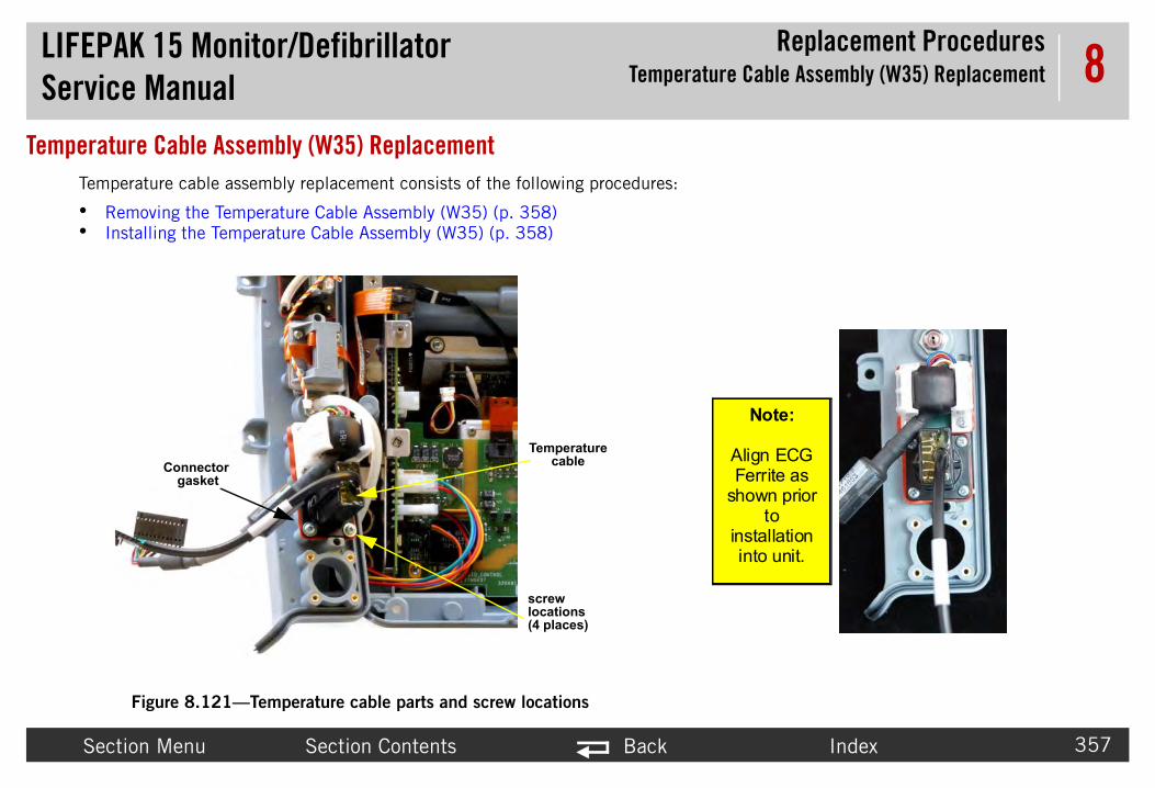
LIFEPAService
Replacement Procedures Cable Assembly (W35) Replacement
Secti Index 357
8Temperatu
Tempe
• Re• Ins
Note:
lign ECG Ferrite as hown prior
to nstallation into unit.
K 15 Monitor/Defibrillator Manual Temperature
on Menu Section Contents Back
re Cable Assembly (W35) Replacementrature cable assembly replacement consists of the following procedures:
moving the Temperature Cable Assembly (W35) (p. 358)talling the Temperature Cable Assembly (W35) (p. 358)
Figure 8.121—Temperature cable parts and screw locations
Temperature cable
screw locations(4 places)
Connector gasket
A
s
i

LIFEPAService
Replacement Procedures Cable Assembly (W35) Replacement
Secti Index 358
8Remo To Case Diagrams (p. 228)):
1.2. ector on the system PCB (A01).3. p. 311).4. e temperature connector to the parameter bezel.5. t.
Instal To ase Diagrams (p. 228)):
NOTE le Repair Kit (MIN 3305431-027) (p. 515).1. nd connector mounting hole up from the bottom of
(3207337-312); torque to 6.8 in-lb. (See Figure
2. 313).
3. A01) at J7.
4.
C
P lp prevent ingress of fluids.
K 15 Monitor/Defibrillator Manual Temperature
on Menu Section Contents Back
ving the Temperature Cable Assembly (W35)remove the temperature cable assembly from the rear case (refer to Inside Rear
Disassemble the case as described in Disassembling the Case (p. 181). Disconnect the temperature cable assembly (3303936-001) from the J7 connRemove the parameter bezel as described in Removing the Parameter Bezel (Remove the four screws and captured washers (3207337-312) that secure thRemove the temperature connector and gasket. Discard the screws and gaske
ling the Temperature Cable Assembly (W35)install the temperature cable assembly into the rear case (refer to Inside Rear C
: When installing a new temperature cable assembly, use the Temperature CabPlace the temperature connector and new gasket (3007998-00) into the secothe parameter bezel. Secure the temperature connector with four new screws8.121 on p. 357 for connector orientation.)
Install the parameter bezel as described in Installing the Parameter Bezel (p.
Connect the temperature cable assembly (3303936-001) to the system PCB (
Reassemble the case as described in Reassembling the Case (p. 184).
AUTION
OSSIBLE MOISTURE LEAKAGE When installing the cable, use new seal to he

LIFEPAService
Replacement ProceduresContact PCB (A07) Replacement
Secti Index 359
8Contact PCContact PCB
• Re• Ins
Remo To
Fig
1.2.
3.
Instal To
1.2.3. ase.4. -000) between the battery wells; torque to
contact PCB
battery retainer
ws
re 8.122—Contact PCB screw and part locations
K 15 Monitor/Defibrillator Manual
on Menu Section Contents Back
B (A07) Replacementreplacement consists of the following procedures:
moving the Contact PCB (A07) (p. 359)talling the Contact PCB (A07) (p. 359)
ving the Contact PCB (A07)remove the contact PCB (3207037-002) (from outside the rear case) (see ure 9.14 on p. 400):
Lay the device face down on a static-free, non-abrasive surface.Remove the two screws (201407-069) from the battery retainer (3207881-000) between the battery wells. Lift away the battery retainer. Discard the screws.Lift the Contact PCB away for rear case far enough to access and disconnect the power/contact PCB cable (3207261-001) (W05) at J42.
ling the Contact PCB (A07)install the contact PCB (3207037-002) on the outside of the rear case:
Lay the device face down on a static-free, non-abrasive surface.Connect the contact PCB to the power/contact PCB cable (W05) at J42.Install the contact PCB by sliding the assembly straight down tracks in rear cInstall the two new screws (201407-069) into the battery retainer (320788110.0 in-lb using P2 bit.
scre
Figu

LIFEPAService
Replacement ProceduresPrinter Assembly (A12) Replacement
Secti Index 360
8Printer AssPrinter assem
• Re• Ins
8.123—Printer assembly replacement
Remo To
1.
2.
3.
4. bly.
5. d the speaker (to disengage the connector on the
K 15 Monitor/Defibrillator Manual
on Menu Section Contents Back
embly (A12) Replacementbly replacement consists of the following procedures:
moving the Printer Assembly (A12) (p. 360)talling the Printer Assembly (A12) (p. 361)
Figure
ving the Printer Assembly (A12)remove the printer assembly from outside the front case:
Lay the device face up on the battery wells.
Remove the printer paper.
Carefully peel away the label from the screw and loosen the screw.
Open the printer door and loosen the two screws from inside the printer assem
Grasp the door near the speaker side, and then gently pull up and push towaropposite side). Lift the printer out and set it aside.

LIFEPAService
Replacement ProceduresPrinter Assembly (A12) Replacement
Secti Index 361
8InstalNOTE To
1.
2. connector (to engage the printer connector)
3. sing a P2 bit.
4.
5. l set (3207318-XXX) to the left front of printer.
6.
K 15 Monitor/Defibrillator Manual
on Menu Section Contents Back
ling the Printer Assembly (A12): The new printer comes with new screws installed to aid reassembly.
install the printer assembly into the front case.
Lay the device face up on the battery wells.
Insert the printer into the front case, and then gently push toward the therapy
Tighten the two screws from inside the printer assembly; torque to 10 in.lb u
Tighten the third screw on the outside left side of printer; torque to 10 in.lb.
Apply a new screw cover label. Apply the screw cover label (#6) from the labe
Install printer paper.

LIFEPAService
Replacement ProceduresCoin Battery Replacement
Secti Index 362
8Coin Batte
Right
K 15 Monitor/Defibrillator Manual
on Menu Section Contents Back
ry Replacement
Figure 8.124—Coin battery location
system PCB (A01)coin battery
LIFEPAService
Replacement ProceduresCoin Battery Replacement
Secti Index 363
8 To replace Case Diagrams (p. 228)):
1. Disa
2. With the coin battery to remove. The coin battery will lace battery into right side of battery holder first
3. Reen
4. The Replacement Items (p. 149)).
K 15 Monitor/Defibrillator Manual
on Menu Section Contents Back
the coin battery on the system PCB (A01) in the rear case (refer to Inside Rear
ssemble the case as described in Disassembling the Case (p. 181).
the new coin battery, (202305-000) (type CR2032), at hand, lift up from belowpop out of the holder. To install, slide in the new battery with (+) terminal up, p. Press down to secure (see Figure 8.124 on p. 362).try of time and date will be required after the coin battery replacement.
coin battery should be part or a five year replacement schedule (see Scheduled

LIFEPAService
Replacement ProceduresBattery Pin Replacement
Secti Index 364
8Battery Pin
Inspec o examine each leaf on the pins to ensure that th that are bent, broken, corroded, worn, or damag
To
1.
2.
eplacement as described in Rear Case s.
battery pins
K 15 Monitor/Defibrillator Manual
on Menu Section Contents Back
Replacement
Figure 8.125—Battery pins
t the battery connector pins as part of the routine physical inspection. Be sure tey are not cracked or broken. Tighten any pins that are loose. Replace any pins ed. Battery pins are replaced from outside the case.
replace a battery pin:
Using a 4 mm modified socket, unscrew the pin and remove it.
Torque the new battery pin (802278-02) to 4 in-lb.
NOTE: The battery grommets are not replaceable. Complete the Rear Case RReplacement (p. 315) procedure to repair damaged battery grommet
battery pins
LIFEPAService
Replacement ProceduresSoftware and Device Upgrades
Secti Index 365
8 Software a
The LI specialized training and entail information proprie d Physio-Control personnel.
For su
K 15 Monitor/Defibrillator Manual
on Menu Section Contents Back
nd Device UpgradesFEPAK 15 monitor/defibrillator software and device upgrade procedures requiretary to Physio-Control. These procedures should only be performed by authorize
pport, contact your local Physio-Control representative for assistance.

LIFEPAService
bly Diagrams and Parts Lists
Secti Index 366
9
AssembThis section i EPAK 15 monitor/defibrillator.
• Se• Ma ct diagram with links to detailed assemblies
and• Fro le of parts for the front of the device• Sys ple diagrams and tables of parts for the
ass• Re arts for the rear of the device• OE iagrams and tables of parts for the
ass• Co 43)—Includes diagrams for parts illustrating
con• Re separate MINs for each kit• Ord• De on the device label, which displays the
maNOTE: nd keypads), click the Select other language
NOTE: ical service, see Devices, Options, Supplies,
K 15 Monitor/Defibrillator Manual
Assem
on Menu Section Contents Back
ly Diagrams and Parts Listss a hierarchical reference used to identify components needed to repair the LIF
ction Glossary (p. 367)—Defines terms used in this sectionin Diagrams (p. 368)—Shows the assembly diagram configurator and interconne partsnt Parts Diagrams and Parts List (p. 377)—Includes multiple diagrams and tabtem/Therapy PCB Assembly Diagrams and Parts Lists (p. 386)—Includes multiemblies of the devicear Diagrams and Parts List (p. 399)—Includes multiple diagrams and table of pM Optional Assemblies, Diagrams and Parts Lists (p. 412)—Includes multiple demblies of the devicennection Diagrams for Assemblies, Control Boards, Cables, and Connectors (p. 4nections
pair Kits (p. 491)—Contains all items needed to replace major components withering Parts (p. 522)—To obtain replacement parts for the device
fibrillator Part Number and Serial Number (p. 521)—Useful for decoding the SNnufacturing code
To view lists of MINs (part numbers) for language options (for example, labels alink (if available) in the Note column of a parts list. For additional parts lists, including items necessary to keep the device in clinand Accessories (p. 65).

LIFEPAService
bly Diagrams and Parts ListsSection Glossary
Secti Index 367
9Section GloThe following
• Co ardless of options and operating language. Co sembly.
• Int
• Ext
• Th s a reference number for parts on the device. Cli
• Th y.• MI
• CA
• Th ist.• PN rillator.• Op ied by the customer when purchased. Parts
on • V1 ature.• V2 A device must be V2-equivalent to order the
Tem
K 15 Monitor/Defibrillator Manual
Assem
on Menu Section Contents Back
ssary are definitions of terms used in this section.
mmon parts are components used in every version of the defibrillator device, regmmon parts are divided into Front Case, Rear Case, and System/Therapy PCB Asernal parts are components internal to the case that are specific to your device.ernal parts are components external to the case that are specific to your device.e Item number on diagrams (used most often for cables and connectors) provideck on the item number in a diagram to jump to that part.e Quantity column identifies how many of the listed part is used in the assemblN refers to the Physio-Control manufacturer’s item number.T. number is used for ordering each part.e Part Description column provides a brief description of each part in the parts l is the part number that identifies the model of each LIFEPAK 15 monitor/defibtions are assemblies that are not required on the basic device and can be specifthese assemblies may be referred to as optional parts. (Version 1) refers to LIFEPAK 15 devices that do not have the auxiliary power fe (Version 2) refers to LIFEPAK 15 devices that have the auxiliary power feature.
perature option.

LIFEPAService
bly Diagrams and Parts ListsMain Diagrams
Secti Index 368
9Main Diagr
Use th
• Ass he device with links to detailed assembly dia
• Int interconnect information and provides links to
K 15 Monitor/Defibrillator Manual
Assem
on Menu Section Contents Back
amse following diagrams for an overview of the device:
embly Diagram Configurator (Figure 9.1 on p. 369)—shows the main parts of tgrams.erconnect Diagram (Figure 9.2 on p. 370)—shows detailed assembly and cableeach part diagram.

LIFEPAService
bly Diagrams and Parts ListsMain Diagrams
Secti Index 369
9
Figure 9.1—A
CB assembly 7)
Rear Case view(p. 400)
External parts view 1 of 2 (front) (p. 372)
K 15 Monitor/Defibrillator Manual
Assem
on Menu Section Contents Back
ssembly diagram configurator
System/Therapy Pview 1 of 2 (p. 38
Front Case parts view 1 of 3 (p. 378)
Parameter Bezel view 1 of 4 (ECG and optional SpO2) (p. 392)
1 of 7

Index 370
links to each part diagram.
W21 W27 W26
perature nnector
Cable
ECG Connector
Cable
SpO2 Connector
CableNIBP
coupler CO2 Inlet Connector
Multiparameter Bezel
J103P103
J104P104
J105P105
J102P102
J108P108
Bridge- (CAP-)
Bridge+
CAP+
Apex
Sternum
J25nnect
Battery Well 1
Battery Well 2
J43 (-)J44 (+)
J43 (-)J44 (+)
Power PCB Bracket
J26P26
J28P28
J27P27
Rear Case
NIBP/CO2 Shield
J106P106
J101P101
tubing tubing
tubeRear
Sp02
Bridge+(CAP+)
Biphasic Module A22
NIBP ModuleSpO2
ModuleCO2
Module
Inductive Resistor
A14
OEM PCB Module A06
USB Flex Assembly
Case
Shield
Shield
Aux Pwr Conn
Contact PCB
Module
W20
W22 W28
0
r
Section Menu Back
Figure 9.2—Interconnect diagram with detailed assembly, cable interconnect information, and
Therapy Connector
Cable
Speed Dial Assembly
Printer Control Keypad Main Keypad
W06
W12 W13
W10
TemCo
123
6 9
8
74
J49P49
J36P36
J35P35
J37P37
J30P30
J33P33
J32P32
J31P31
J41 J39P39
J40P40
J36P38
J21P21
J23P23
J50
J24 P24
J2P2
J5 J7P7
J6P6
J22P22
J18P18
J19P19
J20P20
CoilB3NCA3NC
B1N0
A1N0
+
B2COM
A2COM
Preamp Sternum -
Relay SternumPreamp Apex+
Relay Apex
J1 P1
Direct Co
Board-to-Board
J34P34
J4 P4
System/FRONT CASE
REAR
SBC Shield
J10P10
J51P51
Display Bracket
5
J13P13
J17P17
J8P8
J12P12
J15P15
J11P11
Sense
PowerSBC
Preamp ShieldIsolated
Bluetooth
J10P10
<5>
J9P9
<4>
System PCB A01
Transfer Relay Assembly A13
Interconnect Bracket
Energy Storage Capacitor A15
Therapy PCB A04
Power PCB A03
TherapyShield
Speaker Assembly
Printer Assembly
Backlight PCB
LCD Assembly
Interface PCB A05
J17
W20
W01
W20
W02
W04
W03
W18W16
W19
P41
CASE
W11
W11
W07W35
W05
W1
SystemConnecto
Temp Cable
OR

LIFEPAService
bly Diagrams and Parts ListsExternal Parts Diagrams and Lists
Secti Index 371
9External PaExternal parts
• Ext• Ext• Ext• Ca
K 15 Monitor/Defibrillator Manual
Assem
on Menu Section Contents Back
rts Diagrams and Lists includes the following:
ernal and Configured Parts Diagram — Page 1 of 2 (p. 372)ernal and Configured Parts Diagram — Page 2 of 2 (p. 373)ernal Parts List (p. 374)rrying Case Replacement Parts (p. 376)

LIFEPAService
bly Diagrams and Parts ListsExternal Parts Diagrams and Lists
Secti Index 372
9Extern
3207079-XXX
3207307-001375 (8X)
LABEL 4
K 15 Monitor/Defibrillator Manual
Assem
on Menu Section Contents Back
al and Configured Parts Diagram — Page 1 of 2
Figure 9.3—External parts view 1 of 2 (front)
3207318-XXX
LABEL 1
LABEL 6
3208290-000 3207361-
3207080-XXX
3012120-004
3206968-000 LABEL 11
LABEL 19

LIFEPAService
bly Diagrams and Parts ListsExternal Parts Diagrams and Lists
Secti Index 373
9Extern
3207359-000
3207361-375
3
LABEL 12
LABEL 9
LABEL 2
LABEL 5
K 15 Monitor/Defibrillator Manual
Assem
on Menu Section Contents Back
al and Configured Parts Diagram — Page 2 of 2
Figure 9.4—External parts view 2 of 2 (rear)
3207318-XXX
3206959-001
207318-XXXLABEL 7
LABEL 3
LABEL 9
201407-069 (14X)

LIFEPAService
bly Diagrams and Parts ListsExternal Parts Diagrams and Lists
Secti Index 374
9Extern
Table
MIN otes
32073 fer to Label Set family drawing section, Figure 9.3 on p. 2 and Figure 9.4 on p. 373. See LIFEPAK 15 Label Set anguages (V1) (p. 425)
33056 fer to Label Set family drawing section, Figure 9.3 on p. 2 and Figure 9.4 on p. 373. See LIFEPAK 15 Label Set anguages (V2) (p. 432)
32070 fer to Figure 9.3 on p. 372. See A10 Main Keypad - nguages (V1) (p. 420)
33024 fer to Figure 9.3 on p. 372. See A10 Main Keypad - nguages (V2) (p. 422)
32070 fer to Figure 9.3 on p. 372. See A09- Printer Control ypad - Languages (p. 418)
30121 fer to External and Configured Parts Diagram — Page 1 2 (p. 372)
32082 fer to External and Configured Parts Diagram — Page 1 2 (p. 372). For cable interconnect view, see Figure 32 (p. 454)
32069 fer to Figure 9.4 on p. 373
K 15 Monitor/Defibrillator Manual
Assem
on Menu Section Contents Back
al Parts List
9.1—External Parts
CAT. Qty Description N
18-XXX Multiple 1 LABEL SET, language and feature-specific (V1 - No Auxiliary Power feature)
Re37- L
42-XXX Multiple 1 LABEL SET, language and feature-specific (V2 - Auxiliary Power feature)
Re37- L
79-XXX Multiple 1 A10 -KEYPAD ASSY -MAIN CNTRL (V1 - No Auxiliary Power feature)
ReLa
70-XXX Multiple 1 A10 -KEYPAD ASSY - MAIN CNTRL (V2–Auxiliary Power feature)
ReLa
80-XXX Multiple 1 A09 - KEYPAD ASSY - PRINTER CONTROL ReKe
20-004 21300-007445 1 Cover - CO2 Connector Reof
90-000 11241-000008 1 A12- PRINTER - 100 MM, GRAY Reof9.
59-001 21330-001169 1 Door - Blank, USB Re

LIFEPAService
bly Diagrams and Parts ListsExternal Parts Diagrams and Lists
Secti Index 375
9
32073 fer to External and Configured Parts Diagram — Page 1 2 (p. 372).
32069 fer to External and Configured Parts Diagram — Page 1 2 (p. 372).
32073 fer to External and Configured Parts Diagram — Page 1 2 (p. 372) and External and Configured Parts Diagram Page 2 of 2 (p. 373).
32071 fer to External and Configured Parts Diagram — Page 2 2 (p. 373)
32073 fer to External and Configured Parts Diagram — Page 2 2 (p. 373)
20140 fer to External and Configured Parts Diagram — Page 2 2 (p. 373)
Table
MIN otes
K 15 Monitor/Defibrillator Manual
Assem
on Menu Section Contents Back
07-001 21300-007356 1 Bumper (guard) - Corner, Lower right Reof
68-000 21300-007010 1 Bumper (guard) - Corner, Lower left Reof
61-375 21300-007253 8 Screw-Cap, SCH, Rec, 15IP Torx Plus, 6-32x0.375L,SS
Reof—
31 21501-001997 1 LABEL - SERIAL NUMBER Reof
59-000 21501-001993 1 LABEL - Sp02 MASIMO PATENT (For SpO2 option only)
Reof
7-069 21300-000777 14 SCREW, SEAL-SEAL, SELF-LOCK, 6-32 X 0.375
Reof
9.1—External Parts (Continued)
CAT. Qty Description N

LIFEPAService
bly Diagrams and Parts ListsExternal Parts Diagrams and Lists
Secti Index 376
9CarryReplac 9.2 and Table 9.3.
Table
Min Device - Mounting
32074 S, Nylok Patch mounts carry case at device bottom
20047 S, Nylok Patch mounts carry case at top holes
20225 , Nylok Patch mounts on rear pouch
Table
MIN Notes
32078
32078
32078
30102
K 15 Monitor/Defibrillator Manual
Assem
on Menu Section Contents Back
ing Case Replacement Partsement case parts include screws separately and the bag parts as shown in Table
9.2—Screws for carrying cases
CAT. Qty Description
92-001 21300-007429 4 8-32 x 0.312" Screw, Trusshead, Phillips, S
6-708 21300-007966 2 ¼-20 x 1.00" Screw, Panhead , Phillips, S
3-576 21300-001033 4 6-32 x 0.75" Screw, Panhead, Phillips, SS
9.3—LIFEPAK15 Carrying Case Parts
CAT. Qty Description
24-000 11577-000002 1 Standard Carry Case (w/ Shoulder Strap)
27-002 11260-000039 1 Back Pouch
23-000 11577-000001 1 Shoulder Strap
67-00 11220-000028 1 Top Pouch

LIFEPAService
bly Diagrams and Parts ListsFront Parts Diagrams and Parts List
Secti Index 377
9Front Parts
Use th
• Fro• Fro• Fro• Fro
K 15 Monitor/Defibrillator Manual
Assem
on Menu Section Contents Back
Diagrams and Parts Liste following front parts diagrams and table to identify parts in the front case.
nt Case parts view 1 of 3 (p. 378)nt Case parts view 2 of 3 (p. 379)nt Case parts view 3 of 3 (p. 380)nt Parts List (p. 381)

LIFEPAService
bly Diagrams and Parts ListsFront Parts Diagrams and Parts List
Secti Index 378
9
3011128-002
3207701-000
K 15 Monitor/Defibrillator Manual
Assem
on Menu Section Contents Back
Figure 9.5—Front Case parts view 1 of 3
PART OF 3207030-000
3206726-001
3206724-000
3206725-XXX
3207725-002
3208003-000
3207367-312 (4X)3207030-000
3207361-375 (4X)3207044-002

LIFEPAService
bly Diagrams and Parts ListsFront Parts Diagrams and Parts List
Secti Index 379
9
202253-761 (9X)
09726-03
300
3206991-
320738
3
32069
-00
K 15 Monitor/Defibrillator Manual
Assem
on Menu Section Contents Back
Figure 9.6—Front Case parts view 2 of 3
202253-761 (4X)
202253-764 (4X)
30
9726-01
003
3203221
3206815
3207337-312
202253-761 (2X)
8-001
3206936-0023207252-001
800943-09
207933-000
92-000
3206989-000
3206990-001
3012693
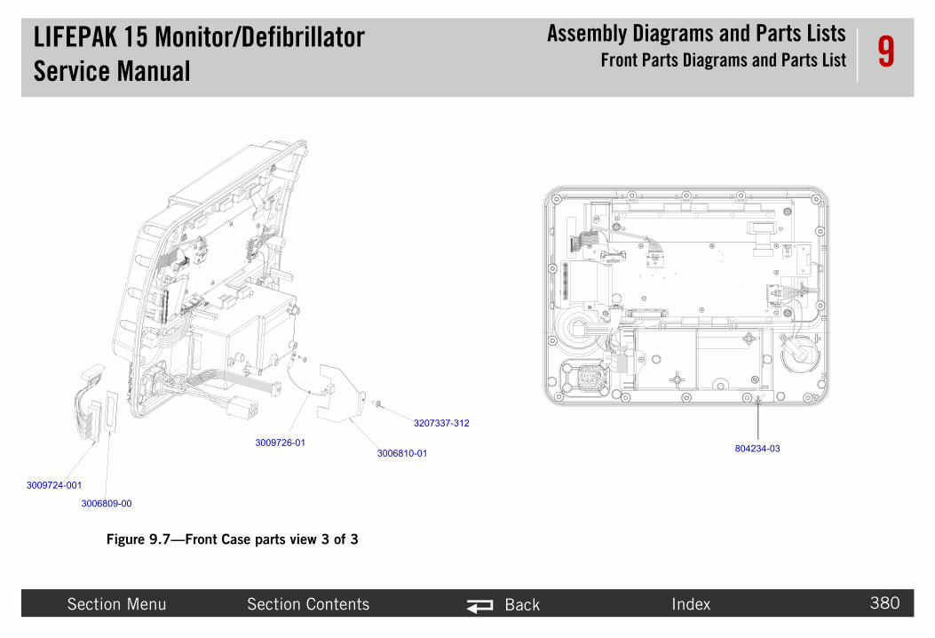
LIFEPAService
bly Diagrams and Parts ListsFront Parts Diagrams and Parts List
Secti Index 380
9
3009724-001
3006
804234-03
K 15 Monitor/Defibrillator Manual
Assem
on Menu Section Contents Back
Figure 9.7—Front Case parts view 3 of 3
3009726-01
3207337-312
3006810-01
809-00
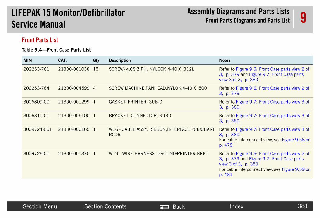
LIFEPAService
bly Diagrams and Parts ListsFront Parts Diagrams and Parts List
Secti Index 381
9FrontTable
MIN Notes
20225 Refer to Figure 9.6: Front Case parts view 2 of 3, p. 379 and Figure 9.7: Front Case parts view 3 of 3, p. 380.
20225 0 Refer to Figure 9.6: Front Case parts view 2 of 3, p. 379.
30068 Refer to Figure 9.7: Front Case parts view 3 of 3, p. 380.
30068 Refer to Figure 9.7: Front Case parts view 3 of 3, p. 380.
30097 HART Refer to Figure 9.7: Front Case parts view 3 of 3, p. 380.For cable interconnect view, see Figure 9.56 on p. 478.
30097 T Refer to Figure 9.6: Front Case parts view 2 of 3, p. 379 and Figure 9.7: Front Case parts view 3 of 3, p. 380.For cable interconnect view, see Figure 9.59 on p. 481
K 15 Monitor/Defibrillator Manual
Assem
on Menu Section Contents Back
Parts List9.4—Front Case Parts List
CAT. Qty Description
3-761 21300-001038 15 SCREW-M,CS,Z,PH, NYLOCK,4-40 X .312L
3-764 21300-004599 4 SCREW,MACHINE,PANHEAD,NYLOK,4-40 X .50
09-00 21300-001299 1 GASKET, PRINTER, SUB-D
10-01 21300-006100 1 BRACKET, CONNECTOR, SUBD
24-001 21330-000165 1 W16 - CABLE ASSY, RIBBON,INTERFACE PCB/CRCDR
26-01 21300-001370 1 W19 - WIRE HARNESS -GROUND/PRINTER BRK
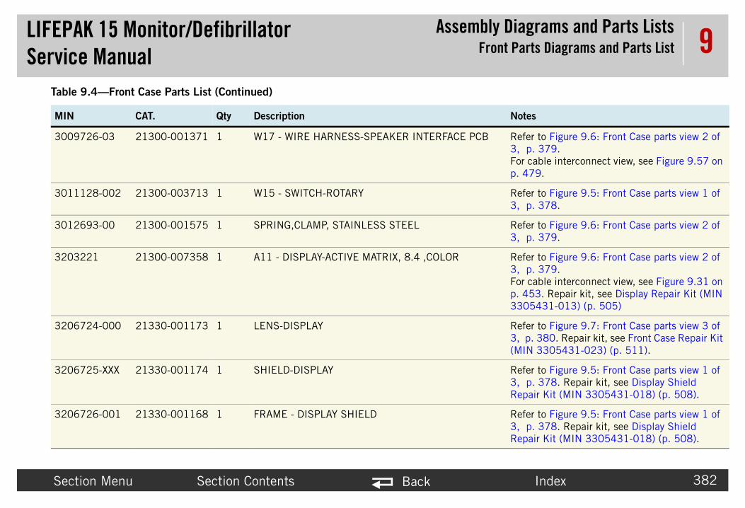
LIFEPAService
bly Diagrams and Parts ListsFront Parts Diagrams and Parts List
Secti Index 382
9
30097 CB Refer to Figure 9.6: Front Case parts view 2 of 3, p. 379.For cable interconnect view, see Figure 9.57 on p. 479.
30111 Refer to Figure 9.5: Front Case parts view 1 of 3, p. 378.
30126 Refer to Figure 9.6: Front Case parts view 2 of 3, p. 379.
32032 Refer to Figure 9.6: Front Case parts view 2 of 3, p. 379.For cable interconnect view, see Figure 9.31 on p. 453. Repair kit, see Display Repair Kit (MIN 3305431-013) (p. 505)
32067 Refer to Figure 9.7: Front Case parts view 3 of 3, p. 380. Repair kit, see Front Case Repair Kit (MIN 3305431-023) (p. 511).
32067 Refer to Figure 9.5: Front Case parts view 1 of 3, p. 378. Repair kit, see Display Shield Repair Kit (MIN 3305431-018) (p. 508).
32067 Refer to Figure 9.5: Front Case parts view 1 of 3, p. 378. Repair kit, see Display Shield Repair Kit (MIN 3305431-018) (p. 508).
Table
MIN Notes
K 15 Monitor/Defibrillator Manual
Assem
on Menu Section Contents Back
26-03 21300-001371 1 W17 - WIRE HARNESS-SPEAKER INTERFACE P
28-002 21300-003713 1 W15 - SWITCH-ROTARY
93-00 21300-001575 1 SPRING,CLAMP, STAINLESS STEEL
21 21300-007358 1 A11 - DISPLAY-ACTIVE MATRIX, 8.4 ,COLOR
24-000 21330-001173 1 LENS-DISPLAY
25-XXX 21330-001174 1 SHIELD-DISPLAY
26-001 21330-001168 1 FRAME - DISPLAY SHIELD
9.4—Front Case Parts List (Continued)
CAT. Qty Description

LIFEPAService
bly Diagrams and Parts ListsFront Parts Diagrams and Parts List
Secti Index 383
9
32068 Refer to Figure 9.6: Front Case parts view 2 of 3, p. 379.For cable interconnect view, see Figure 9.25 (p. 447). Repair kit, see Interface PCBA Repair Kit, V1 (MIN 3305431-005) (p. 499).
33063 Refer to Figure 9.6: Front Case parts view 2 of 3, p. 379.For cable interconnect view, see Figure 9.25 (p. 447). Repair kit, see Interface PCBA Repair Kit, V2 (MIN 3305431-029) (p. 517).
32069 Refer to Figure 9.6: Front Case parts view 2 of 3, p. 379.
32069 AD, Refer to Figure 9.6: Front Case parts view 2 of 3, p. 379.For cable interconnect view, see Figure 9.52 (p. 474).
32069 Refer to Figure 9.6: Front Case parts view 2 of 3, p. 379.For cable interconnect view, see Figure 9.58 (p. 480).
32069 FACE Refer to Figure 9.6: Front Case parts view 2 of 3, p. 379.
Table
MIN Notes
K 15 Monitor/Defibrillator Manual
Assem
on Menu Section Contents Back
15 21330-001236 1 A05 - PCB ASSY - INTERFACE (V1)
67 21330-001447 1 A05 - PCB ASSY - INTERFACE (V2)
36-002 21330-001189 1 BRACKET - LCD DISPLAY MOUNTING
89-000 21330-001214 1 W12 - CABLE ASSY - PRINTER CONTROL KEYPINTERFACE PCB
90-001 21330-001223 1 W18 - CABLE ASSY-FLEX,LCD,INTERFACE PCB
91-003 21330-001226 1 W04 - CABLE ASSY - FLEX, SYSTEM PCB/INTERPCB
9.4—Front Case Parts List (Continued)
CAT. Qty Description

LIFEPAService
bly Diagrams and Parts ListsFront Parts Diagrams and Parts List
Secti Index 384
9
32069 PCB Refer to Figure 9.6: Front Case parts view 2 of 3, p. 379.For cable interconnect view, see Figure 9.46 (p. 468).
32070 Refer to Figure 9.5: Front Case parts view 1 of 3, p. 378.
32070 Refer to Figure 9.5: Front Case parts view 1 of 3, p. 378. Repair kit, see Therapy Connector Repair Kit (MIN 3305431-009) (p. 503)
32072 Refer to Figure 9.6: Front Case parts view 2 of 3, p. 379.
32073 , Refer to Figure 9.6: Front Case parts view 2 of 3, p. 379 and Figure 9.7: Front Case parts view 3 of 3, p. 380
32073 Refer to Figure 9.5: Front Case parts view 1 of 3, p. 378.
32073 Refer to Figure 9.5: Front Case parts view 1 of 3, p. 378.
32073 PCB Refer to Figure 9.6: Front Case parts view 2 of 3, p. 379.For cable interconnect view, see Figure 9.53 on p. 475.
Table
MIN Notes
K 15 Monitor/Defibrillator Manual
Assem
on Menu Section Contents Back
92-000 21330-001215 1 W06 - CABLE ASSY-BACKLIGHT INV,INTERFACE
30-000 21300-007051 1 KNOB-ROTARY SWITCH
44-002 21300-007463 1 W11 - WIRE HARNESS-THERAPY, INTERNAL
52-001 21300-007079 1 SHIELD, INVERTER
37-312 21300-007297 2 SCREW-MACH,PNH,PHH,NYLOCK,4-40, 0.312LWSHR,CS,ZN
61-375 21300-007253 4 SCREW-CAP,SCH,REC 15IP TORX PLUS,6-32,0.375L,SS
67-312 21300-007196 4 SCREW-MACH,TRH,T10 TORX,4-40,0.312L,SS
88-001 21330-001323 1 W13 - CABLE-ASSY,MAIN KEYPAD,INTERFACE
9.4—Front Case Parts List (Continued)
CAT. Qty Description

LIFEPAService
bly Diagrams and Parts ListsFront Parts Diagrams and Parts List
Secti Index 385
9
32077 Refer to Figure 9.5: Front Case parts view 1 of 3, p. 378.
32077 Refer to Figure 9.5: Front Case parts view 1 of 3, p. 378. Repair kit, see Front Case Repair Kit (MIN 3305431-023) (p. 511).
32079 C,85C Refer to Figure 9.6: Front Case parts view 2 of 3, p. 379. Repair kit, see Backlight Inverter Repair Kit (MIN 3305431-012) (p. 505)
32080 Refer to Figure 9.5: Front Case parts view 1 of 3, p. 378.
80094 Refer to Figure 9.6: Front Case parts view 2 of 3, p. 379.
80423 Refer to Figure 9.6: Front Case parts view 2 of 3, p. 379.
Table
MIN Notes
K 15 Monitor/Defibrillator Manual
Assem
on Menu Section Contents Back
01-000 21300-007464 1 SEAL-THERAPY RECEPTAC
25-002 21330-001273 1 ASSEMBLY-ENCLOSURE,FRONT
33-000 21300-007555 1 A08 - INVERTER-BACKLIGHT,DUALTUBE,12VD
03-000 21501-002038 1 LABEL-PHYSIO-CONTROL ICON
3-09 21501-000248 1 LABEL-SYMBOL,INT'L
4-03 21300-002394 1 SEAL-PERIMETER,CASE
9.4—Front Case Parts List (Continued)
CAT. Qty Description
LIFEPAService
bly Diagrams and Parts ListsB Assembly Diagrams and Parts Lists
Secti Index 386
9System/The
Refer
• Sys
K 15 Monitor/Defibrillator Manual
AssemSystem/Therapy PC
on Menu Section Contents Back
rapy PCB Assembly Diagrams and Parts Liststo the following diagrams and parts lists for assemblies.
tem/Therapy PCB Assembly Diagrams and Parts List (p. 387) includes:~ System/Therapy PCB assembly view 1 of 2 (p. 387)~ System/Therapy PCB assembly view 2 of 2 (p. 388)~ System/Therapy Assembly Part Numbers (p. 389)

LIFEPAService
bly Diagrams and Parts ListsB Assembly Diagrams and Parts Lists
Secti Index 387
9Syste
301
20202253-761 (3x)
3009331-00
K 15 Monitor/Defibrillator Manual
AssemSystem/Therapy PC
on Menu Section Contents Back
m/Therapy PCB Assembly Diagrams and Parts List
Figure 9.8—System/Therapy PCB assembly view 1 of 2
202253-550
1630-00
2253-761 (10x)
3306311
3011630-00
3009878-002
3206834
3207010-004

LIFEPAService
bly Diagrams and Parts ListsB Assembly Diagrams and Parts Lists
Secti Index 388
9
2022
K 15 Monitor/Defibrillator Manual
AssemSystem/Therapy PC
on Menu Section Contents Back
Figure 9.9—System/Therapy PCB assembly view 2 of 2
53-761 (6x)
3009331-00 Ref
3306311 Ref
3206834 Ref
3207010-004 Ref
3011629-00

LIFEPAService
bly Diagrams and Parts ListsB Assembly Diagrams and Parts Lists
Secti Index 389
9
Table
MIN Notes
20225 25L See System/Therapy PCB Assembly Diagrams and Parts List (p. 387)
20225 L See System/Therapy PCB Assembly Diagrams and Parts List (p. 387) and Figure 9.9: System/Therapy PCB assembly view 2 of 2, p. 388.
33063 See System/Therapy PCB Assembly Diagrams and Parts List (p. 387) and Figure 9.9: System/Therapy PCB assembly view 2 of 2, p. 388. For cable interconnect view, see Figure 9.22 on p. 444. Repair kit see Therapy PCBA Repair Kit (MIN 3305431-008) (p. 502).
30093 See Figure 9.8: System/Therapy PCB assembly view 1 of 2, p. 387.
30098 W, 30 PIN See Figure 9.8: System/Therapy PCB assembly view 1 of 2, p. 387. For cable interconnect view, see Figure 9.43 on p. 465
30116 See Figure 9.9: System/Therapy PCB assembly view 2 of 2, p. 388.
K 15 Monitor/Defibrillator Manual
AssemSystem/Therapy PC
on Menu Section Contents Back
9.5—System/Therapy Assembly Part Numbers
CATs Qty Description
3-550 21300-001030 1 SCREW-PH, NYLOCK, PHIL,SS,4-40X.1.1
3-761 21300-001038 19 SCREW-M,CS,Z,PH, NYLOCK,4-40 X .312
11 21330-001449 1 A04 - PCB ASSY - THERAPY, BIPHASIC
31-00 21300-001343 1 SHIELD EMI, THERAPY PCB
78-002 21300-001379 1 W03 - CONN-HDR, SQUAREPIN DUAL RO
29-00 21300-001478 1 INSERT-HEX
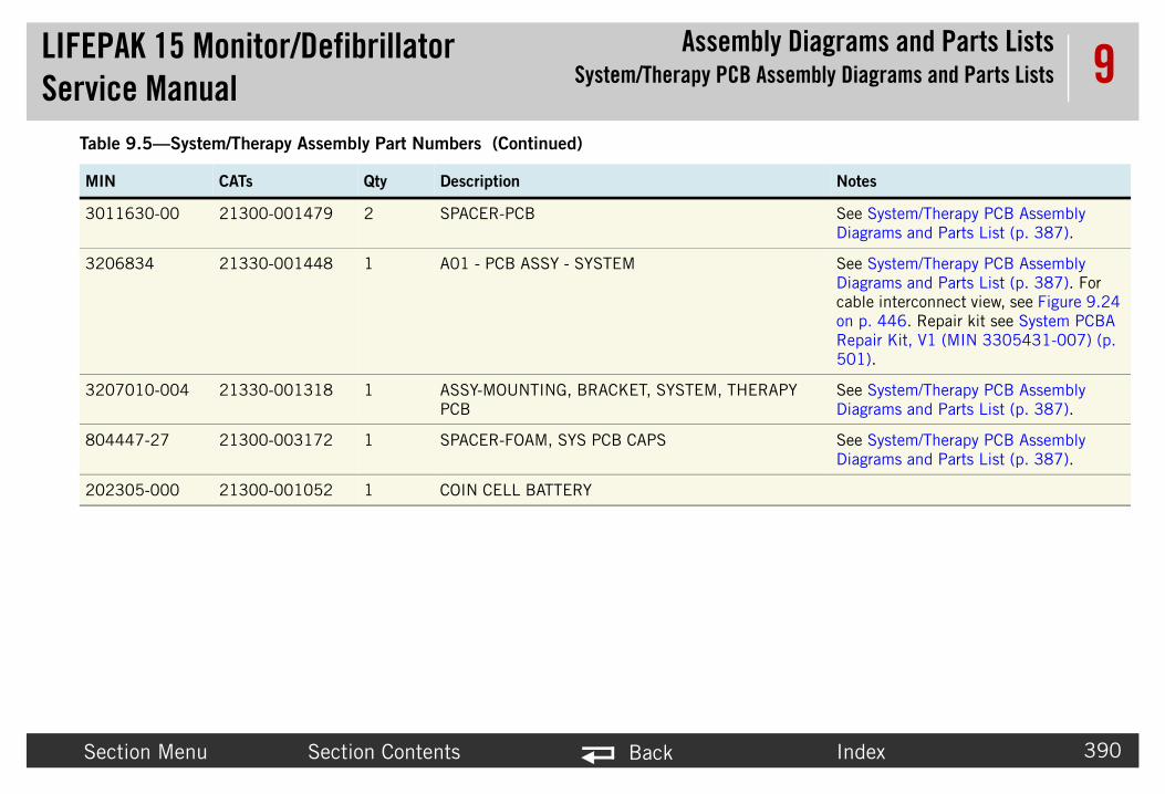
LIFEPAService
bly Diagrams and Parts ListsB Assembly Diagrams and Parts Lists
Secti Index 390
9
30116 See System/Therapy PCB Assembly Diagrams and Parts List (p. 387).
32068 See System/Therapy PCB Assembly Diagrams and Parts List (p. 387). For cable interconnect view, see Figure 9.24 on p. 446. Repair kit see System PCBA Repair Kit, V1 (MIN 3305431-007) (p. 501).
32070 ERAPY See System/Therapy PCB Assembly Diagrams and Parts List (p. 387).
80444 See System/Therapy PCB Assembly Diagrams and Parts List (p. 387).
20230
Table
MIN Notes
K 15 Monitor/Defibrillator Manual
AssemSystem/Therapy PC
on Menu Section Contents Back
30-00 21300-001479 2 SPACER-PCB
34 21330-001448 1 A01 - PCB ASSY - SYSTEM
10-004 21330-001318 1 ASSY-MOUNTING, BRACKET, SYSTEM, THPCB
7-27 21300-003172 1 SPACER-FOAM, SYS PCB CAPS
5-000 21300-001052 1 COIN CELL BATTERY
9.5—System/Therapy Assembly Part Numbers (Continued)
CATs Qty Description

LIFEPAService
bly Diagrams and Parts Listseter Bezel Diagrams and Parts Lists
Secti Index 391
9Parameter
Refer
• Pa
K 15 Monitor/Defibrillator Manual
AssemParam
on Menu Section Contents Back
Bezel Diagrams and Parts Liststo the following diagrams and parts lists for assemblies.
rameter Bezel Diagrams and Parts List (p. 392) includes:~ Parameter Bezel view 1 of 4 (ECG and optional SpO2) (p. 392)~ Parameter Bezel view 2 of 4 (optional CO2 and NIBP) (p. 393)~ Parameter Bezel view 3 of 4 (optional invasive pressure) (p. 394)~ Parameter Bezel Parts List (p. 396)

LIFEPAService
bly Diagrams and Parts Listseter Bezel Diagrams and Parts Lists
Secti Index 392
9Param
06723-005
3207407-000(when no C02)
3007997-01
SpO2 Connector Orientation
K 15 Monitor/Defibrillator Manual
AssemParam
on Menu Section Contents Back
eter Bezel Diagrams and Parts List
Figure 9.10—Parameter Bezel view 1 of 4 (ECG and optional SpO2)
3007991-007 (notch to the top)
202253-763 (4x)
32
3206995-004
3207009-000

LIFEPAService
bly Diagrams and Parts Listseter Bezel Diagrams and Parts Lists
Secti Index 393
9
3207033-001
3012119-02
K 15 Monitor/Defibrillator Manual
AssemParam
on Menu Section Contents Back
Figure 9.11—Parameter Bezel view 2 of 4 (optional CO2 and NIBP)
3012140-008
3012121-002
3007997-01
202253-732 4x
Part of 3207033
3012333-0013012180-02

LIFEPAService
bly Diagrams and Parts Listseter Bezel Diagrams and Parts Lists
Secti Index 394
9
Invasive Pressure Connector Orientation
K 15 Monitor/Defibrillator Manual
AssemParam
on Menu Section Contents Back
Figure 9.12—Parameter Bezel view 3 of 4 (optional invasive pressure)
3007998-00
3200466-01
3207337-312 (8x)
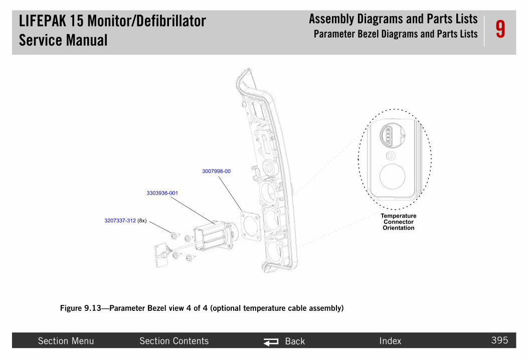
LIFEPAService
bly Diagrams and Parts Listseter Bezel Diagrams and Parts Lists
Secti Index 395
9
ly)
Temperature Connector Orientation
K 15 Monitor/Defibrillator Manual
AssemParam
on Menu Section Contents Back
Figure 9.13—Parameter Bezel view 4 of 4 (optional temperature cable assemb
3007998-00
3303936-001
3207337-312 (8x)

LIFEPAService
bly Diagrams and Parts Listseter Bezel Diagrams and Parts Lists
Secti Index 396
9
Table
MIN
32074 s used in devices without CO2 feature.re 9.10: Parameter Bezel view 1 of 4 (ECG and 2), p. 392.
32067 meter Bezel Diagrams and Parts List (p. 392), Figure eter Bezel view 1 of 4 (ECG and optional SpO2), p. ure 9.12: Parameter Bezel view 3 of 4 (optional sure), p. 394.
30079 re 9.10: Parameter Bezel view 1 of 4 (ECG and 2), p. 392. For cable interconnect view, see Figure 69. Repair kit, see ECG Connector Repair Kit (MIN 0) (p. 503).
80591 re 9.10: Parameter Bezel view 1 of 4 (ECG and 2), p. 392.
32056 re 9.10: Parameter Bezel view 1 of 4 (ECG and 2), p. 392.
20225 re 9.10: Parameter Bezel view 1 of 4 (ECG and 2), p. 392.
32069 re 9.10: Parameter Bezel view 1 of 4 (ECG and 2), p. 392. For cable interconnect view, see Figure 84. Repair kit, see OEM PCBA Repair Kit, V1 (MIN 4) (p. 498).
K 15 Monitor/Defibrillator Manual
AssemParam
on Menu Section Contents Back
9.6—Parameter Bezel Parts List
CAT. Qty. Description Notes
07-000 21300-007362 1 SPACER - CONNECTOR, CO2 This spacer iRefer to Figuoptional SpO
23-005 21330-001211 1 BEZEL - PARAMETER Refer to Para9.10: Param392, and Figinvasive pres
91-007 21300-006323 1 W07 - ECG CABLE ASSY, 12 CONTACT
Refer to Figuoptional SpO9.47 on p. 43305431-01
5-01 21300-002683 1 SEAL-ECG RECEPTACLE Refer to Figuoptional SpO
80-001 21300-006304 2 BRACKET - CABLE SUPPORT, ASSY
Refer to Figuoptional SpO
3-763 21300-006965 4 SCREW, MACHINE, PANHEAD, NYLOK,4-40 X .437
Refer to Figuoptional SpO
95-004 21330-001290 1 W22 - CABLE ASSY - FLEX, MASIMO, Sp02
Refer to Figuoptional SpO9.62 on p. 43305431-00

LIFEPAService
bly Diagrams and Parts Listseter Bezel Diagrams and Parts Lists
Secti Index 397
9
32070 re 9.10: Parameter Bezel view 1 of 4 (ECG and 2), p. 392.
32053 re 9.10: Parameter Bezel view 1 of 4 (ECG and 2), p. 392.
30121 re 9.11: Parameter Bezel view 2 of 4 (optional CO2 p. 393. For cable interconnect view, see Figure 9.65 epair kit, see CO2 Connector Repair Kit (MIN 4) (p. 506).
30079 re 9.11: Parameter Bezel view 2 of 4 (optional CO2 p. 393.
30121 re 9.11: Parameter Bezel view 2 of 4 (optional CO2 p. 393.
30121 re 9.11: Parameter Bezel view 2 of 4 (optional CO2 p. 393.
20225 re 9.11: Parameter Bezel view 2 of 4 (optional CO2 p. 393.
32070 re 9.11: Parameter Bezel view 2 of 4 (optional CO2 p. 393. Repair kit, see NIBP Connector Repair Kit 31-022) (p. 510).
30121 re 9.11: Parameter Bezel view 2 of 4 (optional CO2 p. 393.
Table
MIN
K 15 Monitor/Defibrillator Manual
AssemParam
on Menu Section Contents Back
09-000 21300-007112 1 HOUSING-FERRITE, Sp02 Refer to Figuoptional SpO
11-001 21300-007557 4 SCREW-MACHINE, PAN, T10 - TORX, NYLOK, 4-40 X 0.6875L (Sp02)
Refer to Figuoptional SpO
40-008 21300-007468 1 W28 - FRS ASSEMBLY - CO2, MINI-MODULE, LIFEPAK15
Refer to Figuand NIBP), on p. 487. R3305431-01
97-01 21300-001314 1 SEAL - CO2 CONNECTOR Refer to Figuand NIBP),
19-02 21300-001548 1 ADAPTER - CO2 CONNECTOR Refer to Figuand NIBP),
21-002 21300-007998 1 RETAINER - CO2 CONN Refer to Figuand NIBP),
3-732 21300-007353 4 SCREW-MACH, NYLOK, PHH, 2-56 X 0.500, CS, ZN (CO2)
Refer to Figuand NIBP),
33-001 21300-007425 1 CONNECTOR - PNEUMATIC COUPLER, NIBP
Refer to Figuand NIBP), (MIN 33054
80-02 21300-001560 1 TUBING - NIBP Refer to Figuand NIBP),
9.6—Parameter Bezel Parts List (Continued)
CAT. Qty. Description Notes

LIFEPAService
bly Diagrams and Parts Listseter Bezel Diagrams and Parts Lists
Secti Index 398
9
30123 re 9.11: Parameter Bezel view 2 of 4 (optional CO2 p. 393.
32004 re 9.12: Parameter Bezel view 3 of 4 (optional sure), p. 394. For cable interconnect view, see Figure 90. Repair kit, see Invasive Pressure Connector Repair 5431-001) (p. 496).
30079 re 9.12: Parameter Bezel view 3 of 4 (optional sure), p. 394 and Figure 9.13: Parameter Bezel view al temperature cable assembly), p. 395.
32073 re 9.12: Parameter Bezel view 3 of 4 (optional sure), p. 394.
33039 re 9.13: Parameter Bezel view 4 of 4 (optional cable assembly), p. 395.
Table
MIN
K 15 Monitor/Defibrillator Manual
AssemParam
on Menu Section Contents Back
33-001 21300-001566 1 CONN-PNEU, STR, 0.125ID NYLON, WHT (NIBP)
Refer to Figuand NIBP),
66-01 21300-001583 1 W33 - WIRE HARNESS- INVASIVE PRESSURE 1- 2
Refer to Figuinvasive pres9.68 on p. 4Kit (MIN 330
98-00 21300-001315 2 GASKET - CONNECTOR, INVASIVE PRESURE
Refer to Figuinvasive pres4 of 4 (option
37-312 21300-007297 8 SCREW-MACH,PNH,PHH, NYLOCK, 4-40 X 0.312L, WSHR,CS,ZN (IP)
Refer to Figuinvasive pres
36-001 21330-001484 1 W35 - CONNECTOR CABLE ASSEMBLY - TEMPERATURE
Refer to Figutemperature
9.6—Parameter Bezel Parts List (Continued)
CAT. Qty. Description Notes
LIFEPAService
bly Diagrams and Parts ListsRear Diagrams and Parts List
Secti Index 399
9Rear Diagr
Use th
• Re• Re• Re• Re• Re• Re• Re• Re
K 15 Monitor/Defibrillator Manual
Assem
on Menu Section Contents Back
ams and Parts Liste following diagrams and parts list to identify parts in the rear case.
ar Case view 1 of 7 (p. 400)ar Case view 2 of 7 (p. 401)ar Case view 3 of 7 (p. 402)ar Case view 4 of 7 (p. 403)ar Case view 5 of 7 (p. 404)ar Case view 6 of 7 (p. 405)ar Case view 7 of 7 (p. 406)ar Parts List (p. 407)

LIFEPAService
bly Diagrams and Parts ListsRear Diagrams and Parts List
Secti Index 400
9
200060-011 (2x)
3207726-000
805487-00 (2x)
806091-00 (2x)
-01 (SYS)
K 15 Monitor/Defibrillator Manual
Assem
on Menu Section Contents Back
Figure 9.14—Rear Case view 1 of 7
3009652
3303848-002 (AUX)3207037-002
3207881-000201407-069 (2X)
802278-02 (4x)
3006766-003 (2X)
201407-069 (6X)

LIFEPAService
bly Diagrams and Parts ListsRear Diagrams and Parts List
Secti Index 401
9
3207
K 15 Monitor/Defibrillator Manual
Assem
on Menu Section Contents Back
Figure 9.15—Rear Case view 2 of 7
201407-069 (8x)
708-000 (2x)
3207746-000
3207706-000
3207707-000

LIFEPAService
bly Diagrams and Parts ListsRear Diagrams and Parts List
Secti Index 402
9202253-761 (2x)
3006291-00
K 15 Monitor/Defibrillator Manual
Assem
on Menu Section Contents Back
Figure 9.16—Rear Case view 3 of 7
3206960-002
3009726-083303863-000
201508-000 (4x)
202253-761
3012693-00
3206966-001

LIFEPAService
bly Diagrams and Parts ListsRear Diagrams and Parts List
Secti Index 403
9
202253-761
32069
7261-001
K 15 Monitor/Defibrillator Manual
Assem
on Menu Section Contents Back
Figure 9.17—Rear Case view 4 of 7
202253-761 (6x)
(2x)
3207692-000
3206749-0033302519-002
61-001
3009726-05
320

LIFEPAService
bly Diagrams and Parts ListsRear Diagrams and Parts List
Secti Index 404
9
202253-761 (2x)
3207337-312
3207031-001
3012345-00
3011979-00
3011589-004-010
K 15 Monitor/Defibrillator Manual
Assem
on Menu Section Contents Back
Figure 9.18—Rear Case view 5 of 7
3010178
3011979-01
3010212-02
3207337-312 (2x)
202253-761
3010593-00
3008164-002 3009787-01
200536-011
805542-00800943-09
3008897-002
3201583-001
3011979-02

LIFEPAService
bly Diagrams and Parts ListsRear Diagrams and Parts List
Secti Index 405
9
02253-761 (4x)
69-02
K 15 Monitor/Defibrillator Manual
Assem
on Menu Section Contents Back
Figure 9.19—Rear Case view 6 of 7
2
3206813-003
3206964-001
3207337-312 (3x)
3206965-001
202253-760 (4x)
30105
NIPB, CO2, and Sp02 (p. 413)

LIFEPAService
bly Diagrams and Parts ListsRear Diagrams and Parts List
Secti Index 406
9
200536-001 (6x) DETAIL A(Tie Wrap Location)
3208
761 (7x)
5
K 15 Monitor/Defibrillator Manual
Assem
on Menu Section Contents Back
Figure 9.20—Rear Case view 7 of 7
See Detail A
298-000
202253-763 (2x)
3207337-312 (2x)
3207337-312
202253-
3011792-00

LIFEPAService
bly Diagrams and Parts ListsRear Diagrams and Parts List
Secti Index 407
9Rear Table
MIN Notes
3206733025
Refer to Figure 9.17: Rear Case view 4 of 7, p. 403.See also Figure 9.23 (p. 445) for connection diagram.
3206833063
Refer to Figure 9.18: Rear Case view 5 of 7, p. 404.See also Figure 9.26 (p. 448) for connection diagram.
32070 Refer to Figure 9.14: Rear Case view 1 of 7, p. 400.See also Figure 9.27 (p. 449) for connection diagram.
32015 Refer to Figure 9.18: Rear Case view 5 of 7, p. 404.See also Figure 9.33 (p. 455) for connection diagram.
30102 Refer to Figure 9.18: Rear Case view 5 of 7, p. 404.See also Figure 9.34 (p. 456) for connection diagram.
30081 Refer to Figure 9.18: Rear Case view 5 of 7, p. 404. See also Figure 9.35 on p. 457.
30088 Refer to Figure 9.18: Rear Case view 5 of 7, p. 404. See also Figure 9.37 on p. 459.
30101 Refer to Figure 9.18: Rear Case view 5 of 7, p. 404.See also Figure 9.39 (p. 461) for connections diagram.
32077 Refer to Figure 9.16: Rear Case view 3 of 7, p. 402.
K 15 Monitor/Defibrillator Manual
Assem
on Menu Section Contents Back
Parts List9.7—Rear Parts
CAT. Qty. Description
49-00319-002
21330-00140421330-001408
1 A03 - PCB ASSY - POWER (V1)A03 - PCB ASSY - POWER (V2 Auxiliary Power)
13-00308-000
21330-00128521330-001483
1 A06 - PCB ASSY - OEMA06 - OEM PCB (V2 Auxiliary Power)
37-002 21330-001288 1 A07 - CONTACT ASSY-BATTERY
83-001 21330-000920 1 A13 - RELAY ASSEMBLY - ISOLATION, DPDT, BTE
12-02 21300-001392 1 A14 - INDUCTIVE RESISTOR-5 OHM
64-002 21300-001320 1 A15 - CAPACITOR-ENERGY STORAGE,BTE
97-002 21300-001337 1 A17 - BRACKET-INTERCONNECT
78-010 21330-000176 1 A22 - PCB ASSY - BIPHASIC MODULE, CEDAR (BTE)
26-000 21330-001272 1 ASSEMBLY - ENCLOSURE, REAR

LIFEPAService
bly Diagrams and Parts ListsRear Diagrams and Parts List
Secti Index 408
9
32078 Refer to Figure 9.14: Rear Case view 1 of 7, p. 400.
32070 Refer to Figure 9.18: Rear Case view 5 of 7, p. 404.
32069 Refer to Figure 9.18: Rear Case view 5 of 7, p. 404.
32069 Refer to Figure 9.18: Rear Case view 5 of 7, p. 404.
32069 Refer to Figure 9.17: Rear Case view 4 of 7, p. 403.
30115 Refer to Figure 9.18: Rear Case view 5 of 7, p. 404.
32077 Refer to Figure 9.15: Rear Case view 2 of 7, p. 401.
30117 Refer to Figure 9.18: Rear Case view 5 of 7, p. 404. See also Figure 9.60 (p. 482) for connections diagram.
80227 Refer to Figure 9.14: Rear Case view 1 of 7, p. 400.
30067 Refer to Figure 9.14: Rear Case view 1 of 7, p. 400. Repair kit, Paddle Retainer Repair Kit (MIN 3305431-017) (p. 508).
32077 Refer to Figure 9.15: Rear Case view 2 of 7, p. 401.
32077 Refer to Figure 9.15: Rear Case view 2 of 7, p. 401.
32069 Refer to Figure 9.16: Rear Case view 3 of 7, p. 402.
32077 Refer to Figure 9.15: Rear Case view 2 of 7, p. 401.
Table
MIN Notes
K 15 Monitor/Defibrillator Manual
Assem
on Menu Section Contents Back
81-000 21330-001276 1 ASSEMBLY - RETAINER, BATTERY
31-001 21300-007317 1 BRACKET - CAPACITOR
65-001 21330-001195 1 BRACKET - COVER, OEM MODULES
64-001 21330-001194 1 BRACKET - MOUNTING, OEM MODULES
61-001 21330-001257 1 BRACKET ASSY - POWER PCB
89-004 21300-007546 1 BRACKET - MOUNTING, BTE PCB
08-000 21300-007472 2 BRACKET - SHOULDER STRAP
92-005 21300-001528 1 W20 - CABLE ASSY-FLEX, BTE PCB, THERAPY PCB
8-02 21300-002023 4 CONN-PLUG, BANANA PIN
66-003 21330-001241 2 COVER - LATCH, PADDLE, GRAY (Part of Rear Case Assembly)
46-000 21300-007470 1 COVER PLATE - HANDLE, RIGHT
07-000 21300-007469 1 COVER PLATE - HANDLE, LEFT
60-002 21330-001190 1 GROUND PLANE - FLEXIBLE REAR CASE
06-000 21300-007471 1 HANDLE
9.7—Rear Parts (Continued)
CAT. Qty. Description

LIFEPAService
bly Diagrams and Parts ListsRear Diagrams and Parts List
Secti Index 409
9
80094 Refer to Figure 9.18: Rear Case view 5 of 7, p. 404.
80609 Refer to Figure 9.14: Rear Case view 1 of 7, p. 400.
20150 Refer to Figure 9.16: Rear Case view 3 of 7, p. 402.
80548 Refer to Figure 9.14: Rear Case view 1 of 7, p. 400.
20053 Refer to Figure 9.18: Rear Case view 5 of 7, p. 404.
20053 Refer to Figure 9.20: Rear Case view 7 of 7, p. 406.
20225 Refer to Figure 9.16: Rear Case view 3 of 7, p. 402, Figure 9.17: Rear Case view 4 of 7, p. 403, and Figure 9.18: Rear Case view 5 of 7, p. 404.
20225 Refer to Figure 9.18: Rear Case view 5 of 7, p. 404.
32073 Refer to Figure 9.18: Rear Case view 5 of 7, p. 404.
20140 Refer to Figure 9.14: Rear Case view 1 of 7, p. 400 and Figure 9.15: Rear Case view 2 of 7, p. 401.
20225 Refer to Figure 9.20: Rear Case view 7 of 7, p. 406.
20006 Refer to Figure 9.14: Rear Case view 1 of 7, p. 400.
Table
MIN Notes
K 15 Monitor/Defibrillator Manual
Assem
on Menu Section Contents Back
3-09 21501-000248 1 LABEL - SYMBOL,INT'L
1-00 21300-002691 2 NUT - AUX, SYSTEM, CONN, STAINLESS STEEL
8-000 21300-000804 4 NUT - LOCK, CARBON STEEL, KEP, #4-40 THREAD
7-00 21300-002650 2 PLATE - SEAL, CONNECTOR, REAR
6-011 21300-000504 1 RETNR - CABLE TIE, NYLON, .35W X 21.0 L
6-001 21300-000499 6 RETNR - CABLE TIE, NYLON, .10 W X 4.0 L
3-761 21300-001038 25 SCREW-M,CS,Z,PH, NYLOCK, 4-40 X .312L
3-760 21300-006251 4 SCREW-M, PH, NYLOK, CS, 4-40, .250L
37-312 21300-007297 8 SCREW-MACH, PNH, PHH, NYLOCK, 4-40, 0.312L, WSHR, CS, ZN
7-069 21300-000777 14 SCREW, SELF-SEAL, SELF-LOCK, 6-32 X 0.375
3-763 21300-006965 2 SCREW, MACHINE, PANHEAD, NYLOK, 4-40 X 0.437
0-011 21300-000203 2 SEAL, O-RING,RUBBER, .551ID
9.7—Rear Parts (Continued)
CAT. Qty. Description
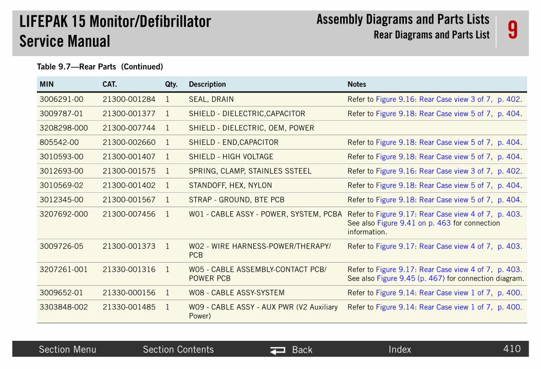
LIFEPAService
bly Diagrams and Parts ListsRear Diagrams and Parts List
Secti Index 410
9
30062 Refer to Figure 9.16: Rear Case view 3 of 7, p. 402.
30097 Refer to Figure 9.18: Rear Case view 5 of 7, p. 404.
32082
80554 Refer to Figure 9.18: Rear Case view 5 of 7, p. 404.
30105 Refer to Figure 9.18: Rear Case view 5 of 7, p. 404.
30126 Refer to Figure 9.16: Rear Case view 3 of 7, p. 402.
30105 Refer to Figure 9.18: Rear Case view 5 of 7, p. 404.
30123 Refer to Figure 9.18: Rear Case view 5 of 7, p. 404.
32076 Refer to Figure 9.17: Rear Case view 4 of 7, p. 403.See also Figure 9.41 on p. 463 for connection information.
30097 Refer to Figure 9.17: Rear Case view 4 of 7, p. 403.
32072 Refer to Figure 9.17: Rear Case view 4 of 7, p. 403.See also Figure 9.45 (p. 467) for connection diagram.
30096 Refer to Figure 9.14: Rear Case view 1 of 7, p. 400.
33038 Refer to Figure 9.14: Rear Case view 1 of 7, p. 400.
Table
MIN Notes
K 15 Monitor/Defibrillator Manual
Assem
on Menu Section Contents Back
91-00 21300-001284 1 SEAL, DRAIN
87-01 21300-001377 1 SHIELD - DIELECTRIC,CAPACITOR
98-000 21300-007744 1 SHIELD - DIELECTRIC, OEM, POWER
2-00 21300-002660 1 SHIELD - END,CAPACITOR
93-00 21300-001407 1 SHIELD - HIGH VOLTAGE
93-00 21300-001575 1 SPRING, CLAMP, STAINLES SSTEEL
69-02 21300-001402 1 STANDOFF, HEX, NYLON
45-00 21300-001567 1 STRAP - GROUND, BTE PCB
92-000 21300-007456 1 W01 - CABLE ASSY - POWER, SYSTEM, PCBA
26-05 21300-001373 1 W02 - WIRE HARNESS-POWER/THERAPY/PCB
61-001 21330-001316 1 W05 - CABLE ASSEMBLY-CONTACT PCB/POWER PCB
52-01 21330-000156 1 W08 - CABLE ASSY-SYSTEM
48-002 21330-001485 1 W09 - CABLE ASSY - AUX PWR (V2 Auxiliary Power)
9.7—Rear Parts (Continued)
CAT. Qty. Description

LIFEPAService
bly Diagrams and Parts ListsRear Diagrams and Parts List
Secti Index 411
9
3009733038
Refer to Figure 9.16: Rear Case view 3 of 7, p. 402.
32069 Refer to Figure 9.16: Rear Case view 3 of 7, p. 402.
30119 Refer to Figure 9.18: Rear Case view 5 of 7, p. 404.
30119 Refer to Figure 9.18: Rear Case view 5 of 7, p. 404.
30119 Refer to Figure 9.18: Rear Case view 5 of 7, p. 404.
Table
MIN Notes
K 15 Monitor/Defibrillator Manual
Assem
on Menu Section Contents Back
26-0863-000
21300-00137421330-001394
1 W10 - WIRE HARNESS, BATTERY POWERW10 - BATTERY POWER (V2 Auxiliary Power)
66-001 21330-001196 1 W14 - FLEX ASSY - USB
79-00 21300-001541 1 WIRE HARNESS-BTE, J103 - PIN 9
79-01 21300-001542 1 WIRE HARNESS-BTE, J101 - PIN 3
79-02 21300-001543 1 WIRE HARNESS-BTE, J105 TO PIN 6
9.7—Rear Parts (Continued)
CAT. Qty. Description

LIFEPAService
bly Diagrams and Parts Listsssemblies, Diagrams and Parts Lists
Secti Index 412
9OEM Option
• NIP• Sp• NIB• CO
K 15 Monitor/Defibrillator Manual
AssemOEM Optional A
on Menu Section Contents Back
al Assemblies, Diagrams and Parts ListsB, CO2, and Sp02 (p. 413)
02 Internal Parts List (p. 414)P Parts List (p. 414)
2 Parts List (p. 415)
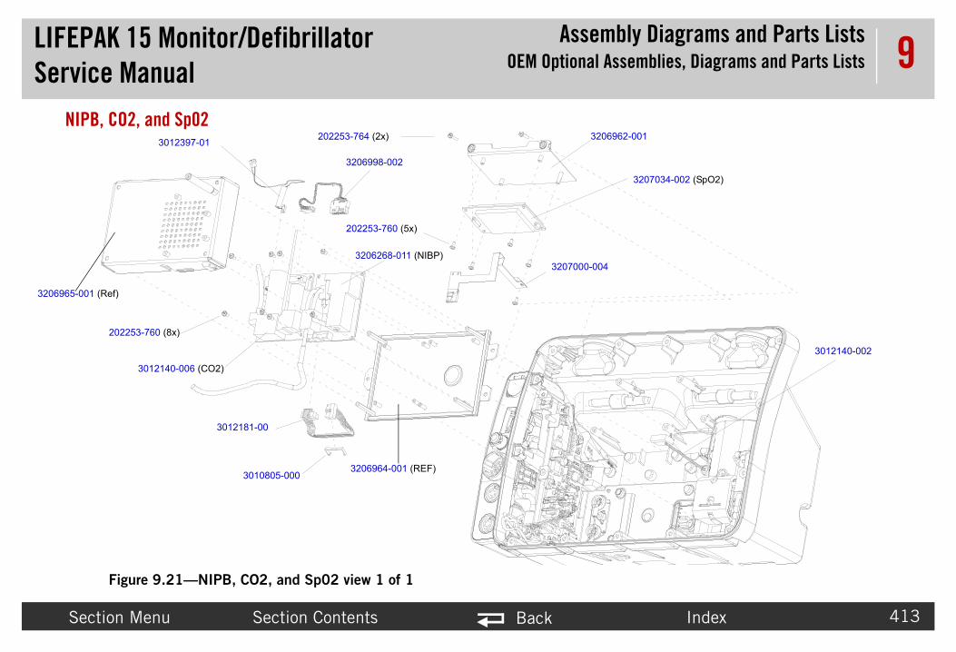
LIFEPAService
bly Diagrams and Parts Listsssemblies, Diagrams and Parts Lists
Secti Index 413
9NIPB,
6962-001
3207034-002 (SpO2)
3012140-002
3206965-001 (R
K 15 Monitor/Defibrillator Manual
AssemOEM Optional A
on Menu Section Contents Back
CO2, and Sp02
Figure 9.21—NIPB, CO2, and Sp02 view 1 of 1
3206964-001 (REF)
202253-764 (2x) 320
3207000-004
202253-760 (5x)
3206268-011 (NIBP)
3012181-00
3010805-000
202253-760 (8x)
3012140-006 (CO2)
3206998-002
3012397-01
ef)

LIFEPAService
bly Diagrams and Parts Listsssemblies, Diagrams and Parts Lists
Secti Index 414
9Sp02 See Fi s table.
NIBP See Fi IPB external connector parts.
Table
MIN Notes
20225
20225 -40 X .500
32069
32070 CB
32070 MX-1
Table
MIN s
20225 r to NIPB, CO2, and Sp02 (p. 413)
30108 r to NIPB, CO2, and Sp02 (p. 413)
30121 r to NIPB, CO2, and Sp02 (p. 413). For cable connect view, see Figure 9.64 (p. 486).
K 15 Monitor/Defibrillator Manual
AssemOEM Optional A
on Menu Section Contents Back
Internal Parts Listgure 9.21: NIPB, CO2, and Sp02 view 1 of 1, p. 413 for the parts listed in thi
Parts Listgure 9.11: Parameter Bezel view 2 of 4 (optional CO2 and NIBP), p. 393 for N
9.8—Sp02 Part Numbers
CAT. Qty Description
3-760 21300-006251 5 SCREW-M, PH, NYLOK, CS, 4-40, .250L
3-764 21300-004599 2 SCREW, MACHINE, PANHEAD, NYLOK, 4
62-001 21300-007550 1 BRACKET - MOUNTING, Sp02 MODULE
00-004 21330-001321 1 W21 - ASSY-CABLE, FLEX, Sp02, OEM, P
34-002 21300-007710 1 A16 - MODULE-OEM, PULSE OXIMETER,
9.9—NIBP Part Numbers
CAT. Qty Description Note
3-760 21300-006251 4 SCREW-M, PH, NYLOK, CS, 4-40, .250L Refe
05-000 21300-001416 1 SOCKET RETAINER CLIP -10PIN Refe
81-00 21330-000235 1 W27 - CABLE ASSY-RIBBON, NIBP/OEM PCB
Refeinter

LIFEPAService
bly Diagrams and Parts Listsssemblies, Diagrams and Parts Lists
Secti Index 415
9
CO2 PSee Fi O2 external connector parts.
33179 r to NIPB, CO2, and Sp02 (p. 413). For cable connect view, see Figure 9.38 (p. 460). Repair addle Retainer Repair Kit (MIN 3305431-017) 08).
32062 r to NIPB, CO2, and Sp02 (p. 413). For cable connect view, see Figure 9.38 (p. 460). Repair addle Retainer Repair Kit (MIN 3305431-017) 08).
Table
MIN Notes
20225 Refer to NIPB, CO2, and Sp02 (p. 413).
30121 Refer to NIPB, CO2, and Sp02 (p. 413).
30121 Refer to NIPB, CO2, and Sp02 (p. 413). For cable interconnect view, see Figure 9.40 (p. 462).
Table
MIN s
K 15 Monitor/Defibrillator Manual
AssemOEM Optional A
on Menu Section Contents Back
arts Listgure 9.11: Parameter Bezel view 2 of 4 (optional CO2 and NIBP), p. 393 for C
65-002 1 A21 Module - NIBP, MaxIQ V5.2, RoHS Refeinterkit, P(p. 5
68-011 21300-007912 1 A21 - NIBP ND+ MODULE, DSP V4.0 AND SAFETY CPU V2.0
Refeinterkit, P(p. 5
9.10—CO2 Part Numbers
CAT. Qty Description
3-760 21300-006251 4 SCREW-M, PH, NYLOK, CS, 4-40, .250L
40-002 21300-001557 1 EXHAUST TUBING - CO2
40-006 21300-006948 1 A23 - MODULE, CO2, MINI
9.9—NIBP Part Numbers
CAT. Qty Description Note

LIFEPAService
bly Diagrams and Parts Listsssemblies, Diagrams and Parts Lists
Secti Index 416
9
30123 Refer to NIPB, CO2, and Sp02 (p. 413). For cable interconnect view, see Figure 9.66 (p. 488).
32069 Refer to NIPB, CO2, and Sp02 (p. 413). For cable interconnect view, see Figure 9.63 (p. 485). Repair kit, CO2 Module Repair Kit (MIN 3305431-002) (p. 497).
Table
MIN Notes
K 15 Monitor/Defibrillator Manual
AssemOEM Optional A
on Menu Section Contents Back
97-01 21330-000237 1 W30 - CABLE ASSY-CO2, ADAPTER
98-002 21330-001217 1 W26 - CABLE ASSY-CO2 MODULE, OEM PCB
9.10—CO2 Part Numbers
CAT. Qty Description

LIFEPAService
bly Diagrams and Parts ListsLabel Language Parts
Secti Index 417
9Label LangLabel languag
• A0• A1• A1• LIF• LIF
K 15 Monitor/Defibrillator Manual
Assem
on Menu Section Contents Back
uage Partse parts include:
9- Printer Control Keypad - Languages (p. 418)0 Main Keypad - Languages (V1) (p. 420)0 Main Keypad - Languages (V2) (p. 422)EPAK 15 Label Set - Languages (V1) (p. 425)EPAK 15 Label Set - Languages (V2) (p. 432)

LIFEPAService
bly Diagrams and Parts ListsLabel Language Parts
Secti Index 418
9A09- PTable
MIN
32070
32070
32070
32070
32070
32070
32070
32070
32070
32070
32070 ese
32070
32070
32070
32070
32070
A09
K 15 Monitor/Defibrillator Manual
Assem
on Menu Section Contents Back
rinter Control Keypad - Languages 9.11— A09 Keypad language parts
CAT. Qty Part Description
80-000 21330-001238 1 Keypad Assy - Printer Control, 12-Lead, English
80-001 21330-001264 1 Keypad Assy - Printer Control, English
80-040 21330-001326 1 Keypad Assy - Printer Control, 12-Lead, German
80-041 21330-001327 1 Keypad Assy - Printer Control, German
80-080 21330-001330 1 Keypad Assy - Printer Control, 12-Lead, French
80-081 21330-001331 1 Keypad Assy - Printer Control, French
80-120 21330-001334 1 Keypad Assy - Printer Control, 12-Lead, Spanish
80-121 21330-001335 1 Keypad Assy - Printer Control, Spanish
80-060 21330-001328 1 Keypad Assy - Printer Control, 12-Lead, Italian
80-061 21330-001329 1 Keypad Assy - Printer Control, Italian
80-140 21330-001383 1 Keypad Assy - Printer Control, 12-Lead, Portugu
80-141 21330-001395 1 Keypad Assy - Printer Control, Portuguese
80-180 21330-001336 1 Keypad Assy - Printer Control, 12-Lead, Swedish
80-181 21330-001337 1 Keypad Assy - Printer Control, Swedish
80-200 21330-001338 1 Keypad Assy - Printer Control, 12-Lead, Danish
80-201 21330-001339 1 Keypad Assy - Printer Control, Danish

LIFEPAService
bly Diagrams and Parts ListsLabel Language Parts
Secti Index 419
9
32070
32070
32070 an
32070
32070
32070
32070
32070
32070 an
32070
32070
32070
32070
32070
32070
32070
32070 e
32070
Table
K 15 Monitor/Defibrillator Manual
Assem
on Menu Section Contents Back
80-220 21330-001384 1 Keypad Assy - Printer Control, 12-Lead, Finnish
80-221 21330-001402 1 Keypad Assy - Printer Control, Finnish
80-240 21330-001340 1 Keypad Assy - Printer Control, 12-Lead, Norwegi
80-241 21330-001341 1 Keypad Assy - Printer Control, Norwegian
80-100 21330-001332 1 Keypad Assy - Printer Control, 12-Lead, Dutch
80-101 21330-001333 1 Keypad Assy - Printer Control, Dutch
80-260 21330-001342 1 Keypad Assy - Printer Control, 12-Lead, Polish
80-261 21330-001343 1 Keypad Assy - Printer Control, Polish
80-280 21330-001385 1 Keypad Assy - Printer Control, 12-Lead, Hungari
80-281 21330-001398 1 Keypad Assy - Printer Control, Hungarian
80-300 21330-001386 1 Keypad Assy - Printer Control, 12-Lead, Czech
80-301 21330-001401 1 Keypad Assy - Printer Control, Czech
80-320 21330-001443 1 Keypad Assy - Printer Control, 12-Lead, Russian
80-321 21330-001444 1 Keypad Assy - Printer Control, Russian
80-380 21330-001445 1 Keypad Assy - Printer Control, 12-Lead, Korean
80-381 21330-001446 1 Keypad Assy - Printer Control, Korean
80-400 21330-001504 1 Keypad Assy - Printer Control, 12-Lead, Japanes
80-401 21330-001505 1 Keypad Assy - Printer Control, Japanese
9.11— A09 Keypad language parts (Continued)

LIFEPAService
bly Diagrams and Parts ListsLabel Language Parts
Secti Index 420
9A10 MTable
MIN
32070 ish
32070
32070 an
32070
32070 n
32070
32070 ch
32070
32070 h
32070
32070 ish
32070
32070 guese
32070
32070 ish
32070
3207079-XXX
K 15 Monitor/Defibrillator Manual
Assem
on Menu Section Contents Back
ain Keypad - Languages (V1) 9.12— A10 Keypad language parts (V1)
CAT. Qty Part Description
79-001 21330-001252 1 Keypad Assy (V1) - Main Cntrl, CPR, NIBP, Engl
79-002 21330-001261 1 Keypad Assy (V1) - Main Cntrl, CPR, English
79-040 21330-001298 1 Keypad Assy (V1) - Main Cntrl, CPR, NIBP, Germ
79-041 21330-001299 1 Keypad Assy (V1)- Main Cntrl, CPR, German
79-060 21330-001300 1 Keypad Assy (V1) - Main Cntrl, CPR, NIBP, Italia
79-061 21330-001301 1 Keypad Assy (V1) - Main Cntrl, CPR, Italian
79-080 21330-001302 1 Keypad Assy (V1) - Main Cntrl, CPR, NIBP, Fren
79-081 21330-001303 1 Keypad Assy (V1) - Main Cntrl, CPR, French
79-100 21330-001304 1 Keypad Assy (V1) - Main Cntrl, CPR, NIBP, Dutc
79-101 21330-001305 1 Keypad Assy (V1) - Main Cntrl, CPR, Dutch
79-120 21330-001306 1 Keypad Assy (V1) - Main Cntrl, CPR, NIBP, Span
79-121 21330-001307 1 Keypad Assy (V1) - Main Cntrl, CPR, Spanish
79-140 21330-001387 1 Keypad Assy (V1) - Main Cntrl, CPR, NIBP, Portu
79-141 21330-001400 1 Keypad Assy (V1) - Main Cntrl, CPR, Portuguese
79-180 21330-001308 1 Keypad Assy (V1) - Main Cntrl, CPR, NIBP, Swed
79-181 21330-001309 1 Keypad Assy (V1) - Main Cntrl, CPR, Swedish

LIFEPAService
bly Diagrams and Parts ListsLabel Language Parts
Secti Index 421
9
32070 sh
32070
32070 ish
32070
32070 egian
32070
32070 h
32070
32070 arian
32070
32070 h
32070
Table
K 15 Monitor/Defibrillator Manual
Assem
on Menu Section Contents Back
79-200 21330-001310 1 Keypad Assy (V1) - Main Cntrl, CPR, NIBP, Dani
79-201 21330-001311 1 Keypad Assy (V1) - Main Cntrl, CPR, Danish
79-220 21330-001388 1 Keypad Assy (V1) - Main Cntrl, CPR, NIBP, Finn
79-221 21330-001399 1 Keypad Assy (V1) - Main Cntrl, CPR, Finnish
79-240 21330-001312 1 Keypad Assy (V1) - Main Cntrl, CPR, NIBP, Norw
79-241 21330-001313 1 Keypad Assy (V1) - Main Cntrl, CPR, Norwegian
79-260 21330-001314 1 Keypad Assy (V1) - Main Cntrl, CPR, NIBP, Polis
79-261 21330-001315 1 Keypad Assy (V1) - Main Cntrl, CPR, Polish
79-280 21330-001389 1 Keypad Assy (V1) - Main Cntrl, CPR, NIBP, Hung
79-281 21330-001397 1 Keypad Assy (V1) - Main Cntrl, CPR, Hungarian
79-300 21330-001390 1 Keypad Assy (V1) - Main Cntrl, CPR, NIBP, Czec
79-301 21330-001396 1 Keypad Assy (V1) - Main Cntrl, CPR, Czech
9.12— A10 Keypad language parts (V1)

LIFEPAService
bly Diagrams and Parts ListsLabel Language Parts
Secti Index 422
9A10 MTable
MIN
33024 lish
33024
33024 an
33024
33024 an
33024
33024 ch
33024
33024 h
33024
33024 nish
33024
33024 uguese
33024
33024 ilian
33024
3302470-XXX
K 15 Monitor/Defibrillator Manual
Assem
on Menu Section Contents Back
ain Keypad - Languages (V2) 9.13— A10 Keypad language parts (V2)
CAT. Qty Part Description
70-002 21330-001496 1 Keypad Assy (V2) - Main Cntrl, CPR, NIBP, Eng
70-003 21330-001497 1 Keypad Assy (V2) - Main Cntrl, CPR, English
70-042 21330-001450 1 Keypad Assy (V2) - Main Cntrl, CPR, NIBP, Germ
70-043 21330-001451 1 Keypad Assy (V2) - Main Cntrl, CPR, German
70-062 21330-001452 1 Keypad Assy (V2) - Main Cntrl, CPR, NIBP, Itali
70-063 21330-001453 1 Keypad Assy (V2) - Main Cntrl, CPR, Italian
70-082 21330-001454 1 Keypad Assy (V2) - Main Cntrl, CPR, NIBP, Fren
70-083 21330-001455 1 Keypad Assy (V2) - Main Cntrl, CPR, French
70-102 21330-001456 1 Keypad Assy (V2) - Main Cntrl, CPR, NIBP, Dutc
70-103 21330-001457 1 Keypad Assy (V2) - Main Cntrl, CPR, Dutch
70-122 21330-001458 1 Keypad Assy (V2) - Main Cntrl, CPR, NIBP, Spa
70-123 21330-001459 1 Keypad Assy (V2) - Main Cntrl, CPR, Spanish
70-142 21330-001460 1 Keypad Assy (V2) - Main Cntrl, CPR, NIBP, Port
70-143 21330-001461 1 Keypad Assy (V2) - Main Cntrl, CPR, Portuguese
70-162 21330-001462 1 Keypad Assy (V2) - Main Cntrl, CPR, NIBP, Braz
70-163 21330-001463 1 Keypad Assy (V2) - Main Cntrl, CPR, Brazilian

LIFEPAService
bly Diagrams and Parts ListsLabel Language Parts
Secti Index 423
9
33024 dish
33024
33024 ish
33024
33024 ish
33024
33024 egian
33024
33024 sh
33024
33024 garian
33024
33024 h
33024
33024 sian
33024
33024 an
33024
Table
K 15 Monitor/Defibrillator Manual
Assem
on Menu Section Contents Back
70-182 21330-001464 1 Keypad Assy (V2) - Main Cntrl, CPR, NIBP, Swe
70-183 21330-001465 1 Keypad Assy (V2) - Main Cntrl, CPR, Swedish
70-202 21330-001466 1 Keypad Assy (V2) - Main Cntrl, CPR, NIBP, Dan
70-203 21330-001469 1 Keypad Assy (V2) - Main Cntrl, CPR, Danish
70-222 21330-001467 1 Keypad Assy (V2) - Main Cntrl, CPR, NIBP, Finn
70-223 21330-001468 1 Keypad Assy (V2) - Main Cntrl, CPR, Finnish
70-242 21330-001474 1 Keypad Assy (V2) - Main Cntrl, CPR, NIBP, Norw
70-243 21330-001470 1 Keypad Assy (V2) - Main Cntrl, CPR, Norwegian
70-262 21330-001471 1 Keypad Assy (V2) - Main Cntrl, CPR, NIBP, Poli
70-263 21330-001472 1 Keypad Assy (V2) - Main Cntrl, CPR, Polish
70-282 21330-001473 1 Keypad Assy (V2) - Main Cntrl, CPR, NIBP, Hun
70-283 21330-001476 1 Keypad Assy (V2) - Main Cntrl, CPR, Hungarian
70-302 21330-001475 1 Keypad Assy (V2) - Main Cntrl, CPR, NIBP, Czec
70-303 21330-001477 1 Keypad Assy (V2) - Main Cntrl, CPR, Czech
70-322 21330-001478 1 Keypad Assy (V2) - Main Cntrl, CPR, NIBP, Rus
70-323 21330-001479 1 Keypad Assy (V2) - Main Cntrl, CPR, Russian
70-382 21330-001480 1 Keypad Assy (V2) - Main Cntrl, CPR, NIBP, Kore
70-383 21330-001481 1 Keypad Assy (V2) - Main Cntrl, CPR, Korean
9.13— A10 Keypad language parts (V2)

LIFEPAService
bly Diagrams and Parts ListsLabel Language Parts
Secti Index 424
9
33024 nese
33024
Table
K 15 Monitor/Defibrillator Manual
Assem
on Menu Section Contents Back
70-400 21330-001506 1 Keypad Assy (V2) - Main Cntrl, CPR, NIBP, Japa
70-401 21330-001507 1 Keypad Assy (V2) - Main Cntrl, CPR, Japanese
9.13— A10 Keypad language parts (V2)

LIFEPAService
bly Diagrams and Parts ListsLabel Language Parts
Secti Index 425
9LIFEPTable
MIN
32073
32073
32073
32073 h
32073
32073
32073
32073
32073
32073
32073 n
32073
32073
K 15 Monitor/Defibrillator Manual
Assem
on Menu Section Contents Back
AK 15 Label Set - Languages (V1)9.14—Label Set Part Numbers (V1)
CAT. Qty Part Description
18-013 21501-002039 1 Label Set (V1) – ECG, English
18-014 21501-002040 1 Label Set (V1) – ECG, Sp02, English
18-015 21501-002041 1 Label Set (V1) – ECG, Sp02, CO2, English
18-016 21501-002042 1 Label Set (V1) – ECG, Sp02, NIBP, IP, Englis
18-017 21501-002043 1 Label Set (V1) – ECG, Sp02, NIBP, CO2, IP, English
18-018 21501-002044 1 Label Set (V1) – ECG, Sp02, NIBP, English
18-019 21501-002045 1 Label Set (V1) – ECG, Sp02, NIBP, CO2, English
18-040 21501-002050 1 Label Set (V1) – ECG, German
18-041 21501-002051 1 Label Set (V1) – ECG, Sp02, German
18-042 21501-002052 1 Label Set (V1) – ECG, Sp02, CO2, German
18-043 21501-002053 1 Label Set (V1) – ECG, Sp02, NIBP, IP, Germa
18-044 21501-002054 1 Label Set (V1) – ECG, Sp02, NIBP, CO2, IP, German
18-045 21501-002055 1 Label Set (V1) – ECG, Sp02, NIBP, German

LIFEPAService
bly Diagrams and Parts ListsLabel Language Parts
Secti Index 426
9
32073
32073
32073
32073
32073
32073
32073
32073 ian
32073
32073
32073
32073 h
32073
32073
32073 ch
Table
MIN
K 15 Monitor/Defibrillator Manual
Assem
on Menu Section Contents Back
18-046 21501-002056 1 Label Set (V1) – ECG, Sp02, NIBP, CO2, German
18-060 21501-002057 1 Label Set (V1) – ECG, Italian
18-061 21501-002058 1 Label Set (V1) – ECG, Sp02, Italian
18-062 21501-002059 1 Label Set (V1) – ECG, Sp02, CO2, Italian
18-063 21501-002060 1 Label Set (V1) – ECG, Sp02, NIBP, IP, Italian
18-064 21501-002061 1 Label Set (V1) – ECG, Sp02, NIBP, CO2, IP, Italian
18-065 21501-002062 1 Label Set (V1) – ECG, Sp02, NIBP, Italian
18-066 21501-002063 1 Label Set (V1) – ECG, Sp02, NIBP, CO2, Ital
18-080 21501-002064 1 Label Set (V1) – ECG, French
18-081 21501-002065 1 Label Set (V1) – ECG, Sp02, French
18-082 21501-002066 1 Label Set (V1) – ECG, Sp02, CO2, French
18-083 21501-002067 1 Label Set (V1) – ECG, Sp02, NIBP, IP, Frenc
18-084 21501-002068 1 Label Set (V1) – ECG, Sp02, NIBP, CO2, IP, French
18-085 21501-002069 1 Label Set (V1) – ECG, Sp02, NIBP, French
18-086 21501-002070 1 Label Set (V1) – ECG, Sp02, NIBP, CO2, Fren
9.14—Label Set Part Numbers (V1) (Continued)
CAT. Qty Part Description

LIFEPAService
bly Diagrams and Parts ListsLabel Language Parts
Secti Index 427
9
32073
32073
32073
32073
32073
32073
32073 ch
32073
32073
32073
32073 sh
32073
32073
32073
32073
Table
MIN
K 15 Monitor/Defibrillator Manual
Assem
on Menu Section Contents Back
18-100 21501-002162 1 Label Set (V1) – ECG, Dutch
18-101 21501-002163 1 Label Set (V1) – ECG, Sp02, Dutch
18-102 21501-002164 1 Label Set (V1) – ECG, Sp02, CO2, Dutch
18-103 21501-002165 1 Label Set (V1) – ECG, Sp02, NIBP, IP, Dutch
18-104 21501-002166 1 Label Set (V1) – ECG, Sp02, NIBP, CO2, IP, Dutch
18-105 21501-002167 1 Label Set (V1) – ECG, Sp02, NIBP, Dutch
18-106 21501-002168 1 Label Set (V1) – ECG, Sp02, NIBP, CO2, Dut
18-120 21501-002169 1 Label Set (V1) – ECG, Spanish
18-121 21501-002170 1 Label Set (V1) – ECG, Sp02, Spanish
18-122 21501-002171 1 Label Set (V1) – ECG, Sp02, CO2, Spanish
18-123 21501-002172 1 Label Set (V1) – ECG, Sp02, NIBP, IP, Spani
18-124 21501-002173 1 Label Set (V1) – ECG, Sp02, NIBP, CO2, IP, Spanish
18-125 21501-002174 1 Label Set (V1) – ECG, Sp02, NIBP, Spanish
18-126 21501-002175 1 Label Set (V1) – ECG, Sp02, NIBP, CO2, Spanish
18-140 21501-002297 1 Label Set (V1) – ECG, Portuguese
9.14—Label Set Part Numbers (V1) (Continued)
CAT. Qty Part Description

LIFEPAService
bly Diagrams and Parts ListsLabel Language Parts
Secti Index 428
9
32073
32073 e
32073
32073
32073 se
32073
32073
32073
32073
32073 sh
32073
32073
32073
Table
MIN
K 15 Monitor/Defibrillator Manual
Assem
on Menu Section Contents Back
18-141 21501-002298 1 Label Set (V1) – ECG, Sp02, Portuguese
18-142 21501-002299 1 Label Set (V1) – ECG, Sp02, CO2, Portugues
18-143 21501-002300 1 Label Set (V1) – ECG, Sp02, NIBP, IP, Portuguese
18-144 21501-002301 1 Label Set (V1) – ECG, Sp02, NIBP, CO2, IP, Portuguese
18-145 21501-002302 1 Label Set (V1) – ECG, Sp02, NIBP, Portugue
18-146 21501-002303 1 Label Set (V1) – ECG, Sp02, NIBP, CO2, Portuguese
18-180 21501-002176 1 Label Set (V1) – ECG, Swedish
18-181 21501-002177 1 Label Set (V1) – ECG, Sp02, Swedish
18-182 21501-002178 1 Label Set (V1) – ECG, Sp02, CO2, Swedish
18-183 21501-002179 1 Label Set (V1) – ECG, Sp02, NIBP, IP, Swedi
18-184 21501-002180 1 Label Set (V1) – ECG, Sp02, NIBP, CO2, IP, Swedish
18-185 21501-002181 1 Label Set (V1) – ECG, Sp02, NIBP, Swedish
18-186 21501-002182 1 Label Set (V1) – ECG, Sp02, NIBP, CO2, Swedish
9.14—Label Set Part Numbers (V1) (Continued)
CAT. Qty Part Description

LIFEPAService
bly Diagrams and Parts ListsLabel Language Parts
Secti Index 429
9
32073
32073
32073
32073 h
32073
32073
32073 ish
32073
32073
32073
32073 h
32073
32073
32073
32073
Table
MIN
K 15 Monitor/Defibrillator Manual
Assem
on Menu Section Contents Back
18-200 21501-002183 1 Label Set (V1) – ECG, Danish
18-201 21501-002184 1 Label Set (V1) – ECG, Sp02, Danish
18-202 21501-002185 1 Label Set (V1) – ECG, Sp02, CO2, Danish
18-203 21501-002186 1 Label Set (V1) – ECG, Sp02, NIBP, IP, Danis
18-204 21501-002187 1 Label Set (V1) – ECG, Sp02, NIBP, CO2, IP, Danish
18-205 21501-002188 1 Label Set (V1) – ECG, Sp02, NIBP, Danish
18-206 21501-002189 1 Label Set (V1) – ECG, Sp02, NIBP, CO2, Dan
18-220 21501-002304 1 Label Set (V1) – ECG, Finnish
18-221 21501-002305 1 Label Set (V1) – ECG, Sp02, Finnish
18-222 21501-002306 1 Label Set (V1) – ECG, Sp02, CO2, Finnish
18-223 21501-002307 1 Label Set (V1) – ECG, Sp02, NIBP, IP, Finnis
18-224 21501-002308 1 Label Set (V1) – ECG, Sp02, NIBP, CO2, IP, Finnish
18-225 21501-002309 1 Label Set (V1) – ECG, Sp02, NIBP, Finnish
18-226 21501-002310 1 Label Set (V1) – ECG, Sp02, NIBP, CO2, Finnish
18-240 21501-002190 1 Label Set (V1) – ECG, Norwegian
9.14—Label Set Part Numbers (V1) (Continued)
CAT. Qty Part Description

LIFEPAService
bly Diagrams and Parts ListsLabel Language Parts
Secti Index 430
9
32073
32073
32073
32073
32073 n
32073
32073
32073
32073
32073
32073
32073
32073 ish
32073
Table
MIN
K 15 Monitor/Defibrillator Manual
Assem
on Menu Section Contents Back
18-241 21501-002191 1 Label Set (V1) – ECG, Sp02, Norwegian
18-242 21501-002192 1 Label Set (V1) – ECG, Sp02, CO2, Norwegian
18-243 21501-002193 1 Label Set (V1) – ECG, Sp02, NIBP, IP, Norwegian
18-244 21501-002194 1 Label Set (V1) – ECG, Sp02, NIBP, CO2, IP, Norwegian
18-245 21501-002195 1 Label Set (V1) – ECG, Sp02, NIBP, Norwegia
18-246 21501-002196 1 Label Set (V1) – ECG, Sp02, NIBP, CO2, Norwegian
18-260 21501-002197 1 Label Set (V1) – ECG, Polish
18-261 21501-002198 1 Label Set (V1) – ECG, Sp02, Polish
18-262 21501-002199 1 Label Set (V1) – ECG, Sp02, CO2, Polish
18-263 21501-002200 1 Label Set (V1) – ECG, Sp02, NIBP, IP, Polish
18-264 21501-002201 1 Label Set (V1) – ECG, Sp02, NIBP, CO2, IP, Polish
18-265 21501-002202 1 Label Set (V1) – ECG, Sp02, NIBP, Polish
18-266 21501-002203 1 Label Set (V1) – ECG, Sp02, NIBP, CO2, Pol
18-280 21501-002283 1 Label Set (V1) – ECG, Hungarian
9.14—Label Set Part Numbers (V1) (Continued)
CAT. Qty Part Description

LIFEPAService
bly Diagrams and Parts ListsLabel Language Parts
Secti Index 431
9
32073
32073
32073
32073
32073 n
32073
32073
32073
32073
32073
32073
32073
32073 ch
Table
MIN
K 15 Monitor/Defibrillator Manual
Assem
on Menu Section Contents Back
18-281 21501-002284 1 Label Set (V1) – ECG, Sp02, Hungarian
18-282 21501-002285 1 Label Set (V1) – ECG, Sp02, CO2, Hungarian
18-283 21501-002286 1 Label Set (V1) – ECG, Sp02, NIBP, IP, Hungarian
18-284 21501-002287 1 Label Set (V1) – ECG, Sp02, NIBP, CO2, IP, Hungarian
18-285 21501-002288 1 Label Set (V1) – ECG, Sp02, NIBP, Hungaria
18-286 21501-002289 1 Label Set (V1) – ECG, Sp02, NIBP, CO2, Hungarian
18-300 21501-002290 1 Label Set (V1) – ECG, Czech
18-301 21501-002291 1 Label Set (V1) – ECG, Sp02, Czech
18-302 21501-002292 1 Label Set (V1) – ECG, Sp02, CO2, Czech
18-303 21501-002293 1 Label Set (V1) – ECG, Sp02, NIBP, IP, Czech
18-304 21501-002294 1 Label Set (V1) – ECG, Sp02, NIBP, CO2, IP, Czech
18-305 21501-002295 1 Label Set (V1) – ECG, Sp02, NIBP, Czech
18-306 21501-002296 1 Label Set (V1) – ECG, Sp02, NIBP, CO2, Cze
9.14—Label Set Part Numbers (V1) (Continued)
CAT. Qty Part Description

LIFEPAService
bly Diagrams and Parts ListsLabel Language Parts
Secti Index 432
9LIFEPTable
MIN
33056
33056
33056
33056
33056
33056 h
33056
33056 p,
33056
33056
33056
33056
33056
K 15 Monitor/Defibrillator Manual
Assem
on Menu Section Contents Back
AK 15 Label Set - Languages (V2)9.15—Label Set Part Numbers (V2)
CAT. Qty Part Description
42-000 21501-002408 1 Label Set (V2) – ECG, English
42-001 21501-002409 1 Label Set (V2) – ECG, SpO2, English
42-002 21501-002410 1 Label Set (V2) – ECG, NIBP, SpO2, English
42-003 21501-002411 1 Label Set (V2) – ECG, SpO2, CO2, English
42-004 21501-002412 1 Label Set (V2) – ECG, SpO2, NIBP, CO2, English
42-005 21501-002413 1 Label Set (V2) – ECG, SpO2, NIBP, IP, Englis
42-006 21501-002414 1 Label Set (V2) – ECG, SpO2, NIBP, CO2, IP, English
42-007 21501-002415 1 Label Set (V2) – ECG, SpO2, NIBP, CO2, TemEnglish
42-040 21501-002475 1 Label Set (V2) – ECG, German
42-041 21501-002476 1 Label Set (V2) – ECG, SpO2, German
42-042 21501-002477 1 Label Set (V2) – ECG, NIBP, SpO2, German
42-043 21501-002478 1 Label Set (V2) – ECG, SpO2, CO2, German
42-044 21501-002479 1 Label Set (V2) – ECG, SpO2, NIBP, CO2, German

LIFEPAService
bly Diagrams and Parts ListsLabel Language Parts
Secti Index 433
9
33056 an
33056
33056 p,
33056
33056
33056
33056
33056 ian
33056
33056
33056 p,
33056
33056
33056
Table
MIN
K 15 Monitor/Defibrillator Manual
Assem
on Menu Section Contents Back
42-045 21501-002545 1 Label Set (V2) – ECG, SpO2, NIBP, IP, Germ
42-046 21501-002546 1 Label Set (V2) – ECG, SpO2, NIBP, CO2, IP, German
42-047 21501-002547 1 Label Set (V2) – ECG, SpO2, NIBP, CO2, TemGerman
42-060 21501-002548 1 Label Set (V2) – ECG, Italian
42-061 21501-002549 1 Label Set (V2) – ECG, SpO2, Italian
42-062 21501-002550 1 Label Set (V2) – ECG, NIBP, SpO2, Italian
42-063 21501-002551 1 Label Set (V2) – ECG, SpO2, CO2, Italian
42-064 21501-002552 1 Label Set (V2) – ECG, SpO2, NIBP, CO2, Ital
42-065 21501-002553 1 Label Set (V2) – ECG, SpO2, NIBP, IP, Italian
42-066 21501-002554 1 Label Set (V2) – ECG, SpO2, NIBP, CO2, IP, Italian
42-067 21501-002555 1 Label Set (V2) – ECG, SpO2, NIBP, CO2, TemItalian
42-080 21501-002480 1 Label Set (V2) – ECG, French
42-081 21501-002481 1 Label Set (V2) – ECG, SpO2, French
42-082 21501-002482 1 Label Set (V2) – ECG, NIBP, SpO2, French
9.15—Label Set Part Numbers (V2) (Continued)
CAT. Qty Part Description

LIFEPAService
bly Diagrams and Parts ListsLabel Language Parts
Secti Index 434
9
33056
33056
33056 h
33056
33056 p,
33056
33056
33056
33056
33056 ch
33056
33056
33056 p,
Table
MIN
K 15 Monitor/Defibrillator Manual
Assem
on Menu Section Contents Back
42-083 21501-002483 1 Label Set (V2) – ECG, SpO2, CO2, French
42-084 21501-002484 1 Label Set (V2) – ECG, SpO2, NIBP, CO2, French
42-085 21501-002485 1 Label Set (V2) – ECG, SpO2, NIBP, IP, Frenc
42-086 21501-002486 1 Label Set (V2) – ECG, SpO2, NIBP, CO2, IP, French
42-087 21501-002487 1 Label Set (V2) – ECG, SpO2, NIBP, CO2, TemFrench
42-100 21501-002488 1 Label Set (V2) – ECG, Dutch
42-101 21501-002489 1 Label Set (V2) – ECG, SpO2, Dutch
42-102 21501-002527 1 Label Set (V2) – ECG, NIBP, SpO2, Dutch
42-103 21501-002528 1 Label Set (V2) – ECG, SpO2, CO2, Dutch
42-104 21501-002529 1 Label Set (V2) – ECG, SpO2, NIBP, CO2, Dut
42-105 21501-002530 1 Label Set (V2) – ECG, SpO2, NIBP, IP, Dutch
42-106 21501-002536 1 Label Set (V2) – ECG, SpO2, NIBP, CO2, IP, Dutch
42-107 21501-002500 1 Label Set (V2) – ECG, SpO2, NIBP, CO2, TemDutch
9.15—Label Set Part Numbers (V2) (Continued)
CAT. Qty Part Description

LIFEPAService
bly Diagrams and Parts ListsLabel Language Parts
Secti Index 435
9
33056
33056
33056
33056
33056
33056 sh
33056
33056 p,
33056
33056
33056 se
33056 e
33056
Table
MIN
K 15 Monitor/Defibrillator Manual
Assem
on Menu Section Contents Back
42-120 21501-002531 1 Label Set (V2) – ECG, Spanish
42-121 21501-002532 1 Label Set (V2) – ECG, SpO2, Spanish
42-122 21501-002533 1 Label Set (V2) – ECG, NIBP, SpO2, Spanish
42-123 21501-002534 1 Label Set (V2) – ECG, SpO2, CO2, Spanish
42-124 21501-002535 1 Label Set (V2) – ECG, SpO2, NIBP, CO2, Spanish
42-125 21501-002491 1 Label Set (V2) – ECG, SpO2, NIBP, IP, Spani
42-126 21501-002493 1 Label Set (V2) – ECG, SpO2, NIBP, CO2, IP, Spanish
42-127 21501-002494 1 Label Set (V2) – ECG, SpO2, NIBP, CO2, TemSpanish
42-140 21501-002501 1 Label Set (V2) – ECG, Portuguese
42-141 21501-002502 1 Label Set (V2) – ECG, SpO2, Portuguese
42-142 21501-002503 1 Label Set (V2) – ECG, NIBP, SpO2, Portugue
42-143 21501-002504 1 Label Set (V2) – ECG, SpO2, CO2, Portugues
42-144 21501-002505 1 Label Set (V2) – ECG, SpO2, NIBP, CO2, Portuguese
9.15—Label Set Part Numbers (V2) (Continued)
CAT. Qty Part Description

LIFEPAService
bly Diagrams and Parts ListsLabel Language Parts
Secti Index 436
9
33056
33056
33056 p,
33056
33056
33056
33056
33056
33056 ian
33056
33056 p,
33056
33056
Table
MIN
K 15 Monitor/Defibrillator Manual
Assem
on Menu Section Contents Back
42-145 21501-002506 1 Label Set (V2) – ECG, SpO2, NIBP, IP, Portuguese
42-146 21501-002507 1 Label Set (V2) – ECG, SpO2, NIBP, CO2, IP, Portuguese
42-147 21501-002508 1 Label Set (V2) – ECG, SpO2, NIBP, CO2, TemPortuguese
42-160 21501-002509 1 Label Set (V2) – ECG, Brazilian
42-161 21501-002557 1 Label Set (V2) – ECG, SpO2, Brazilian
42-162 21501-002558 1 Label Set (V2) – ECG, NIBP, SpO2, Brazilian
42-163 21501-002559 1 Label Set (V2) – ECG, SpO2, CO2, Brazilian
42-164 21501-002560 1 Label Set (V2) – ECG, SpO2, NIBP, CO2, Brazilian
42-165 21501-002561 1 Label Set (V2) – ECG, SpO2, NIBP, IP, Brazil
42-166 21501-002562 1 Label Set (V2) – ECG, SpO2, NIBP, CO2, IP, Brazilian
42-167 21501-002556 1 Label Set (V2) – ECG, SpO2, NIBP, CO2, TemBrazilian
42-180 21501-002510 1 Label Set (V2) – ECG, Swedish
42-181 21501-002511 1 Label Set (V2) – ECG, SpO2, Swedish
9.15—Label Set Part Numbers (V2) (Continued)
CAT. Qty Part Description

LIFEPAService
bly Diagrams and Parts ListsLabel Language Parts
Secti Index 437
9
33056
33056
33056
33056 ish
33056
33056 p,
33056
33056
33056
33056
33056
33056 h
33056
Table
MIN
K 15 Monitor/Defibrillator Manual
Assem
on Menu Section Contents Back
42-182 21501-002512 1 Label Set (V2) – ECG, NIBP, SpO2, Swedish
42-183 21501-002513 1 Label Set (V2) – ECG, SpO2, CO2, Swedish
42-184 21501-002490 1 Label Set (V2) – ECG, SpO2, NIBP, CO2, Swedish
42-185 21501-002492 1 Label Set (V2) – ECG, SpO2, NIBP, IP, Swed
42-186 21501-002495 1 Label Set (V2) – ECG, SpO2, NIBP, CO2, IP, Swedish
42-187 21501-002496 1 Label Set (V2) – ECG, SpO2, NIBP, CO2, TemSwedish
42-200 21501-002497 1 Label Set (V2) – ECG, Danish
42-201 21501-002498 1 Label Set (V2) – ECG, SpO2, Danish
42-202 21501-002499 1 Label Set (V2) – ECG, NIBP, SpO2, Danish
42-203 21501-002514 1 Label Set (V2) – ECG, SpO2, CO2, Danish
42-204 21501-002515 1 Label Set (V2) – ECG, SpO2, NIBP, CO2, Danish
42-205 21501-002516 1 Label Set (V2) – ECG, SpO2, NIBP, IP, Danis
42-206 21501-002517 1 Label Set (V2) – ECG, SpO2, NIBP, CO2, IP, Danish
9.15—Label Set Part Numbers (V2) (Continued)
CAT. Qty Part Description

LIFEPAService
bly Diagrams and Parts ListsLabel Language Parts
Secti Index 438
9
33056 p,
33056
33056
33056
33056
33056
33056 h
33056
33056 p,
33056
33056
33056 n
33056
Table
MIN
K 15 Monitor/Defibrillator Manual
Assem
on Menu Section Contents Back
42-207 21501-002518 1 Label Set (V2) – ECG, SpO2, NIBP, CO2, TemDanish
42-220 21501-002519 1 Label Set (V2) – ECG, Finnish
42-221 21501-002520 1 Label Set (V2) – ECG, SpO2, Finnish
42-222 21501-002521 1 Label Set (V2) – ECG, NIBP, SpO2, Finnish
42-223 21501-002522 1 Label Set (V2) – ECG, SpO2, CO2, Finnish
42-224 21501-002523 1 Label Set (V2) – ECG, SpO2, NIBP, CO2, Finnish
42-225 21501-002524 1 Label Set (V2) – ECG, SpO2, NIBP, IP, Finnis
42-226 21501-002525 1 Label Set (V2) – ECG, SpO2, NIBP, CO2, IP, Finnish
42-227 21501-002526 1 Label Set (V2) – ECG, SpO2, NIBP, CO2, TemFinnish
42-240 21501-002537 1 Label Set (V2) – ECG, Norwegian
42-241 21501-002538 1 Label Set (V2) – ECG, SpO2, Norwegian
42-242 21501-002540 1 Label Set (V2) – ECG, NIBP, SpO2, Norwegia
42-243 21501-002539 1 Label Set (V2) – ECG, SpO2, CO2, Norwegian
9.15—Label Set Part Numbers (V2) (Continued)
CAT. Qty Part Description

LIFEPAService
bly Diagrams and Parts ListsLabel Language Parts
Secti Index 439
9
33056
33056
33056
33056 p,
33056
33056
33056
33056
33056 ish
33056
33056
33056 p,
33056
Table
MIN
K 15 Monitor/Defibrillator Manual
Assem
on Menu Section Contents Back
42-244 21501-002541 1 Label Set (V2) – ECG, SpO2, NIBP, CO2, Norwegian
42-245 21501-002542 1 Label Set (V2) – ECG, SpO2, NIBP, IP, Norwegian
42-246 21501-002543 1 Label Set (V2) – ECG, SpO2, NIBP, CO2, IP, Norwegian
42-247 21501-002544 1 Label Set (V2) – ECG, SpO2, NIBP, CO2, TemNorwegian
42-260 21501-002563 1 Label Set (V2) – ECG, Polish
42-261 21501-002564 1 Label Set (V2) – ECG, SpO2, Polish
42-262 21501-002565 1 Label Set (V2) – ECG, NIBP, SpO2, Polish
42-263 21501-002566 1 Label Set (V2) – ECG, SpO2, CO2, Polish
42-264 21501-002567 1 Label Set (V2) – ECG, SpO2, NIBP, CO2, Pol
42-265 21501-002568 1 Label Set (V2) – ECG, SpO2, NIBP, IP, Polish
42-266 21501-002569 1 Label Set (V2) – ECG, SpO2, NIBP, CO2, IP, Polish
42-267 21501-002570 1 Label Set (V2) – ECG, SpO2, NIBP, CO2, TemPolish
42-280 21501-002571 1 Label Set (V2) – ECG, Hungarian
9.15—Label Set Part Numbers (V2) (Continued)
CAT. Qty Part Description

LIFEPAService
bly Diagrams and Parts ListsLabel Language Parts
Secti Index 440
9
33056
33056 n
33056
33056
33056
33056
33056 p,
33056
33056
33056
33056
33056 ch
33056
Table
MIN
K 15 Monitor/Defibrillator Manual
Assem
on Menu Section Contents Back
42-281 21501-002572 1 Label Set (V2) – ECG, SpO2, Hungarian
42-282 21501-002573 1 Label Set (V2) – ECG, NIBP, SpO2, Hungaria
42-283 21501-002574 1 Label Set (V2) – ECG, SpO2, CO2, Hungarian
42-284 21501-002575 1 Label Set (V2) – ECG, SpO2, NIBP, CO2, Hungarian
42-285 21501-002576 1 Label Set (V2) – ECG, SpO2, NIBP, IP, Hungarian
42-286 21501-002577 1 Label Set (V2) – ECG, SpO2, NIBP, CO2, IP, Hungarian
42-287 21501-002578 1 Label Set (V2) – ECG, SpO2, NIBP, CO2, TemHungarian
42-300 21501-002579 1 Label Set (V2) – ECG, Czech
42-301 21501-002580 1 Label Set (V2) – ECG, SpO2, Czech
42-302 21501-002581 1 Label Set (V2) – ECG, NIBP, SpO2, Czech
42-303 21501-002582 1 Label Set (V2) – ECG, SpO2, CO2, Czech
42-304 21501-002583 1 Label Set (V2) – ECG, SpO2, NIBP, CO2, Cze
42-305 21501-002584 1 Label Set (V2) – ECG, SpO2, NIBP, IP, Czech
9.15—Label Set Part Numbers (V2) (Continued)
CAT. Qty Part Description

LIFEPAService
bly Diagrams and Parts ListsLabel Language Parts
Secti Index 441
9
33056
33056 p,
33056
33056
33056
33056
33056
33056 an
33056
33056 p,
33056
33056
33056
Table
MIN
K 15 Monitor/Defibrillator Manual
Assem
on Menu Section Contents Back
42-306 21501-002585 1 Label Set (V2) – ECG, SpO2, NIBP, CO2, IP, Czech
42-307 21501-002586 1 Label Set (V2) – ECG, SpO2, NIBP, CO2, TemCzech
42-320 21501-002587 1 Label Set (V2) – ECG, Russian
42-321 21501-002588 1 Label Set (V2) – ECG, SpO2, Russian
42-322 21501-002589 1 Label Set (V2) – ECG, NIBP, SpO2, Russian
42-323 21501-002590 1 Label Set (V2) – ECG, SpO2, CO2, Russian
42-324 21501-002591 1 Label Set (V2) – ECG, SpO2, NIBP, CO2, Russian
42-325 21501-002592 1 Label Set (V2) – ECG, SpO2, NIBP, IP, Russi
42-326 21501-002593 1 Label Set (V2) – ECG, SpO2, NIBP, CO2, IP, Russian
42-327 21501-002594 1 Label Set (V2) – ECG, SpO2, NIBP, CO2, TemRussian
42-380 21501-002595 1 Label Set (V2) – ECG, Korean
42-381 21501-002596 1 Label Set (V2) – ECG, SpO2, Korean
42-382 21501-002597 1 Label Set (V2) – ECG, NIBP, SpO2, Korean
9.15—Label Set Part Numbers (V2) (Continued)
CAT. Qty Part Description
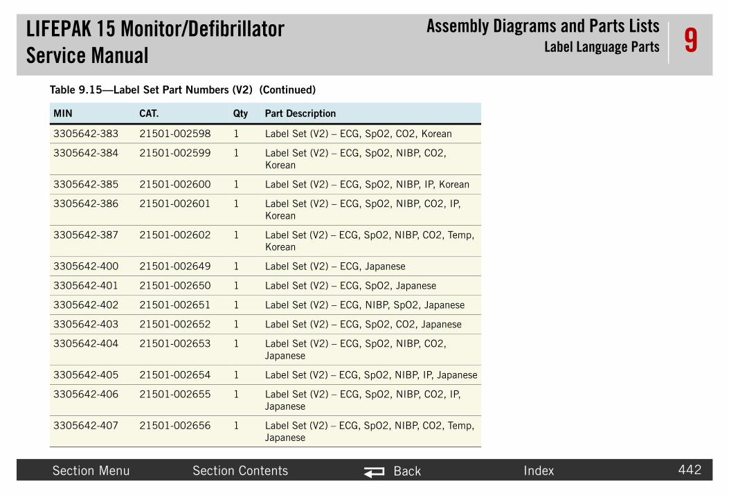
LIFEPAService
bly Diagrams and Parts ListsLabel Language Parts
Secti Index 442
9
33056
33056
33056 n
33056
33056 p,
33056
33056
33056
33056
33056
33056 ese
33056
33056 p,
Table
MIN
K 15 Monitor/Defibrillator Manual
Assem
on Menu Section Contents Back
42-383 21501-002598 1 Label Set (V2) – ECG, SpO2, CO2, Korean
42-384 21501-002599 1 Label Set (V2) – ECG, SpO2, NIBP, CO2, Korean
42-385 21501-002600 1 Label Set (V2) – ECG, SpO2, NIBP, IP, Korea
42-386 21501-002601 1 Label Set (V2) – ECG, SpO2, NIBP, CO2, IP, Korean
42-387 21501-002602 1 Label Set (V2) – ECG, SpO2, NIBP, CO2, TemKorean
42-400 21501-002649 1 Label Set (V2) – ECG, Japanese
42-401 21501-002650 1 Label Set (V2) – ECG, SpO2, Japanese
42-402 21501-002651 1 Label Set (V2) – ECG, NIBP, SpO2, Japanese
42-403 21501-002652 1 Label Set (V2) – ECG, SpO2, CO2, Japanese
42-404 21501-002653 1 Label Set (V2) – ECG, SpO2, NIBP, CO2, Japanese
42-405 21501-002654 1 Label Set (V2) – ECG, SpO2, NIBP, IP, Japan
42-406 21501-002655 1 Label Set (V2) – ECG, SpO2, NIBP, CO2, IP, Japanese
42-407 21501-002656 1 Label Set (V2) – ECG, SpO2, NIBP, CO2, TemJapanese
9.15—Label Set Part Numbers (V2) (Continued)
CAT. Qty Part Description

LIFEPAService
bly Diagrams and Parts Listsemblies, Control Boards, Cables, and
Connectors
Secti Index 443
9Connection orsThis section i• Therap• Power P• System• Interfac• OEM P• Contac• Backlig• Printer • Main K• LCD As• Printer • Transfe
455)• Inducti• Energy
457)• SpO2 M• Interco• NIBP M• Biphas• CO2 M• Power P
(p. 463
• Printer Assembly/Interface PCB Cable (p. 478)
• Speaker Assembly (p. 479)• LCD Assembly/Interface PCB
Cable (p. 480)• Printer Assembly/Chassis
Ground Cable (p. 481)• Biphasic to Therapy PCB Flex
Cable (p. 482)• OEM PCB/SpO2 Module Cable
(p. 483)• SpO2 Connector Cable (p. 484)• OEM PCB/CO2 Module Cable (p.
485)• OEM PCB/NIBP Module Cable
(p. 486)OEM PCB/NIBP Module Cable (p. 486)
• CO2 Inlet Connector Cable (p. 487)
• Temperature Connector Cable Assembly (p. 490)
K 15 Monitor/Defibrillator Manual
AssemConnection Diagrams for Ass
on Menu Section Contents Back
Diagrams for Assemblies, Control Boards, Cables, and Connectncluded diagrams for the following assemblies and parts:y PCB (p. 446)CB (p. 445)
PCB (p. 444)e PCB (p. 447)
CB Module (p. 448)t PCB Module (p. 449)ht PCB (p. 450)Control Keypad (p. 451)eypad (p. 452)sembly (p. 453)Assembly (p. 454)r Relay Assembly (p.
ve Resistor (p. 456)Storage Capacitor (p.
odule (p. 458)nnect Bracket (p. 459)odule (p. 460)
ic Module (p. 461)odule (p. 462)CB/System PCB Cable )
• Power PCB/Therapy PCB Cable (p. 464)
• System PCB/Therapy PCB Connector (p. 465)
• System PCB/Interface PCB Cable (p. 466)
• Power PCB/Contact PCB Cable (p. 467)
• Backlight PCB/Interface PCB Cable (p. 468)
• ECG Connector Cable (p. 469)• System Connector Cable (p.
470)• Battery Pins/Power PCB Cable
(p. 472)• Therapy Connector Cable (p.
473)• Printer Control Keypad/Interface
PCB Cable (p. 474)• Main Keypad/Interface PCB
Cable (p. 475)• USB Flex Assembly (p. 476)

LIFEPAService
bly Diagrams and Parts Listsemblies, Control Boards, Cables, and
Connectors
Secti Index 444
9Syste
J2
System PCB/Interface PCB Cable (p. 466)
C
J10
Refer to Syste erapy PCB assemblySee also MIN
K 15 Monitor/Defibrillator Manual
AssemConnection Diagrams for Ass
on Menu Section Contents Back
m PCB
Figure 9.22—Diagram for item A01
J4
J5
J1
Power PCB/Contact PCB
Cable (p. 467)
USB Flex Assembly (p. 476)
ECG Connector Cable (p. 469)
System PCB/Therapy PCB
onnector (p. 465)
Invasive Pressure Assembly (p. 489) J6
J7
m/Therapy PCB Assembly Diagrams and Parts List (p. 387) and Figure 9.9: System/Th view 2 of 2, p. 388
3206834 in table for parts information.
Temperature Connector Cable

LIFEPAService
bly Diagrams and Parts Listsemblies, Control Boards, Cables, and
Connectors
Secti Index 445
9Powe
Refer to Fig403.See MIN 3information
J12
J08
J16
J15-A
J11
J15-B J09 J10
J17
s/B 2)
er r (p.
Power PCB, V2 with Aux. Power
K 15 Monitor/Defibrillator Manual
AssemConnection Diagrams for Ass
on Menu Section Contents Back
r PCB
Figure 9.23—Diagram for item A03
J12
J08
J16
J13
J11
J15
J09 J10
Power PCB/Therapy PCB Cable (p. 464)
System Connector Cable (p. 470)
Battery Pins/Power PCB Cable (p. 472)
OEM PCB Module (p. 448)
Power PCB/System PCB Cable (p. 463)
Power PCB/Contact PCB Cable (p. 467)
ure 9.17: Rear Case view 4 of 7, p.
206749-003 in table for parts .
J17
Battery PinPower PC
Cable (p. 47
Auxiliary PowConnecto
Cable (V2) 471)
Aux Power Cable (V1)

LIFEPAService
bly Diagrams and Parts Listsemblies, Control Boards, Cables, and
Connectors
Secti Index 446
9Thera
System PCB/Therapy PCB Connector (p. 465)
Power PCB/Therapy PCB Cable (p. 464)elay
(p.
J50
J20
BiphasicPCB Fle
4
Transfer RelaAssembly (p. 45
Refer to Syste erapy PCB assemblySee also MIN
K 15 Monitor/Defibrillator Manual
AssemConnection Diagrams for Ass
on Menu Section Contents Back
py PCB
Figure 9.24—Diagram for item A04
Transfer RAssembly
455)
Energy Storage Capacitor (p.
457)
Transfer Relay Assembly (p.
455)
Therapy Connector Cable
(p. 473)
J51
J21
J18
J19
J22
to Therapy x Cable (p. 82)
J23
y 5)
m/Therapy PCB Assembly Diagrams and Parts List (p. 387) and Figure 9.9: System/Th view 2 of 2, p. 388
3306311 in table for parts information.

LIFEPAService
bly Diagrams and Parts Listsemblies, Control Boards, Cables, and
Connectors
Secti Index 447
9Interf
LCD Assembly/Interface PCB Cable (p. 480)
System PCInterface PCCable (p. 46
Main KeypInterface PCable (p. 4
Speaker Assembly (p. 479)
Printer Control Keypad/Interface
PCB Cable (p. 474)
Refer to See MIN
J34
J32
J36
J39
K 15 Monitor/Defibrillator Manual
AssemConnection Diagrams for Ass
on Menu Section Contents Back
ace PCB
Figure 9.25—Diagram for item A05
B/B 6)
ad/CB 75)
Speed Dial Assembly (p. 477) Printer Assembly/Interface
PCB Cable (p. 478)
Figure 9.6: Front Case parts view 2 of 3, p. 379. 3206815 in table for parts information.
J30
J37
J35J33
J31
Backlight PCB/Interface PCB Cable (p. 468)

LIFEPAService
bly Diagrams and Parts Listsemblies, Control Boards, Cables, and
Connectors
Secti Index 448
9OEM P
Power PCB (p. 445)
27
J28
OEM PCB/CO2 Module Cable (p. 485)
OEM PCB/NIBP Module Cable
(p. 486)
Refer to FigurSee MIN 320
K 15 Monitor/Defibrillator Manual
AssemConnection Diagrams for Ass
on Menu Section Contents Back
CB Module
Figure 9.26—Diagram for item A06
J25
OEM PCB/SpO2 Module Cable (p. 483)
J26
J
e 9.18: Rear Case view 5 of 7, p. 404.6813-003 in table for parts information.

LIFEPAService
bly Diagrams and Parts Listsemblies, Control Boards, Cables, and
Connectors
Secti Index 449
9Conta
Refer to FiguSee MIN 320
K 15 Monitor/Defibrillator Manual
AssemConnection Diagrams for Ass
on Menu Section Contents Back
ct PCB Module
Figure 9.27—Diagram for item A07
J42J56
Power PCB/Contact PCB
Cable (p. 467) battery edge
re 9.14: Rear Case view 1 of 7, p. 400.7037-002 in table for parts information.

LIFEPAService
bly Diagrams and Parts Listsemblies, Control Boards, Cables, and
Connectors
Secti Index 450
9Backl
LCDAssem(p. 45
Refer to FSee MIN
LCD Assembly (p. 453)
K 15 Monitor/Defibrillator Manual
AssemConnection Diagrams for Ass
on Menu Section Contents Back
ight PCB
Figure 9.28—Diagram for item A08
bly 3)
Backlight PCB/Interface PCB Cable (p. 468)
igure 9.6: Front Case parts view 2 of 3, p. 379. 3207933-000 in table for parts information.
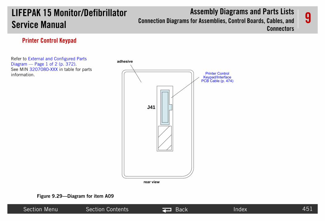
LIFEPAService
bly Diagrams and Parts Listsemblies, Control Boards, Cables, and
Connectors
Secti Index 451
9Printe
rinter Control ypad/Interface
B Cable (p. 474)
Refer to ExteDiagram — PSee MIN 32information.
K 15 Monitor/Defibrillator Manual
AssemConnection Diagrams for Ass
on Menu Section Contents Back
r Control Keypad
Figure 9.29—Diagram for item A09
J41
adhesive
PKe
PC
rear view
rnal and Configured Parts age 1 of 2 (p. 372).
07080-XXX in table for parts

LIFEPAService
bly Diagrams and Parts Listsemblies, Control Boards, Cables, and
Connectors
Secti Index 452
9Main
Refer to Exter2 (p. 372).See MIN 320
K 15 Monitor/Defibrillator Manual
AssemConnection Diagrams for Ass
on Menu Section Contents Back
Keypad
Figure 9.30—Diagram for item A10
adhesive
Main Keypad/Interface
PCB Cable (p. 475)
rear view
nal and Configured Parts Diagram — Page 1 of
7079-XXX in table for parts information.
J39

LIFEPAService
bly Diagrams and Parts Listsemblies, Control Boards, Cables, and
Connectors
Secti Index 453
9LCD A
LCD Assembly/Interface PCB Cable
(p. 480)
Refer to FigurSee MIN 320
K 15 Monitor/Defibrillator Manual
AssemConnection Diagrams for Ass
on Menu Section Contents Back
ssembly
Figure 9.31—Diagram for item A11
Backlight PCB (p. 450)
e 9.6: Front Case parts view 2 of 3, p. 379.3221 in table for parts information.
Backlight PCB (p. 450)

LIFEPAService
bly Diagrams and Parts Listsemblies, Control Boards, Cables, and
Connectors
Secti Index 454
9Printe
nter Assembly/face PCB Cable
(p. 478)
See MItable fo
K 15 Monitor/Defibrillator Manual
AssemConnection Diagrams for Ass
on Menu Section Contents Back
r Assembly
Figure 9.32—Diagram for item A12
100-mm printer
J40
PriInter
N 3208290-000 in r parts information.

LIFEPAService
bly Diagrams and Parts Listsemblies, Control Boards, Cables, and
Connectors
Secti Index 455
9Trans
12
13
A1A2A3B1B2B3
7
104
P21
54321
12345
P24
654321
wiring diagram
P18
T
red
red
redredred
redredwhite
Refer to FigurCase view 5 ofSee MIN 3201table for parts
K 15 Monitor/Defibrillator Manual
AssemConnection Diagrams for Ass
on Menu Section Contents Back
fer Relay Assembly
Figure 9.33—Diagram for item A13
1
P22
2
redblack
XX
A
herapy PCB (p. 446)
Therapy PCB (p. 446)
Therapy Connector Cable (p.
473) Interconnect Bracket (p. 459)
Biphasic Module (p. 461)
P21 P18
P22
P24
pin 5 pin 1
A3B3 B2 B1A2
A1
x2x1
pin 1
e 9.18: Rear 7, p. 404.583-001 in
information.
Therapy PCB (p. 446)
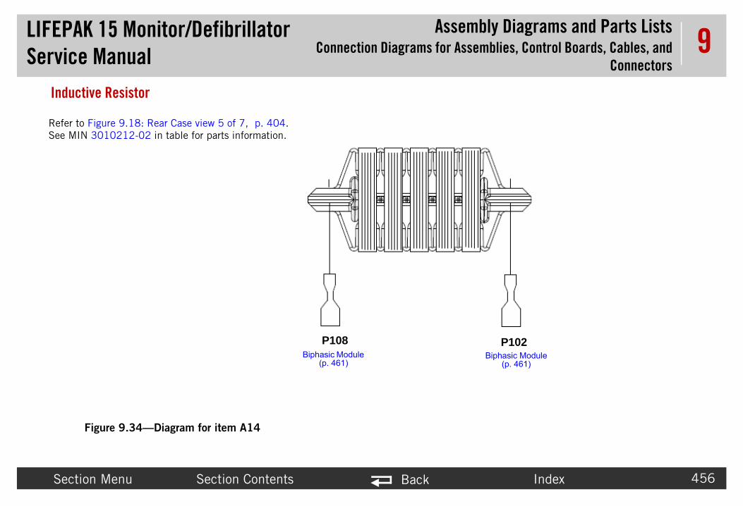
LIFEPAService
bly Diagrams and Parts Listsemblies, Control Boards, Cables, and
Connectors
Secti Index 456
9Induc
P102Biphasic Module
(p. 461)
Refer toSee MI
K 15 Monitor/Defibrillator Manual
AssemConnection Diagrams for Ass
on Menu Section Contents Back
tive Resistor
Figure 9.34—Diagram for item A14
P108Biphasic Module
(p. 461)
Figure 9.18: Rear Case view 5 of 7, p. 404.N 3010212-02 in table for parts information.

LIFEPAService
bly Diagrams and Parts Listsemblies, Control Boards, Cables, and
Connectors
Secti Index 457
9Energy
Refer to FiguSee MIN 300
K 15 Monitor/Defibrillator Manual
AssemConnection Diagrams for Ass
on Menu Section Contents Back
Storage Capacitor
Figure 9.35—Diagram for item A15
+
P19
1
4Pin 1
Interconnect Bracket (p. 459)
Interconnect Bracket (p. 459)
Therapy PCB (p. 446)
re 9.18: Rear Case view 5 of 7, p. 404.8164-002 in table for parts information.

LIFEPAService
bly Diagrams and Parts Listsemblies, Control Boards, Cables, and
Connectors
Secti Index 458
9SpO2
OEM PCB/SpO2 Module Cable (p. 483)
Refer 413.See M
J3
K 15 Monitor/Defibrillator Manual
AssemConnection Diagrams for Ass
on Menu Section Contents Back
Module
Figure 9.36—Diagram for item A16
SpO2 Connector Cable (p. 484)
to Figure 9.21: NIPB, CO2, and Sp02 view 1 of 1, p.
IN 3207034-002 in table for parts information.
J1

LIFEPAService
bly Diagrams and Parts Listsemblies, Control Boards, Cables, and
Connectors
Secti Index 459
9Interc
Refer toSee MIN
Connection ChartA17 -pin 1 Cap Neg (wht)A17 -pin 3 BTE J101A17 -pin 4 Cap Pos (red)A17 -pin 6 BTE J105A17 -pin 7 Relay pin 7A17 -pin 9 BTE J103
K 15 Monitor/Defibrillator Manual
AssemConnection Diagrams for Ass
on Menu Section Contents Back
onnect Bracket
Figure 9.37—Diagram for item A17
1 2 3
4
7
5 6
8 9
Figure 9.18: Rear Case view 5 of 7, p. 404. 3008897-002 in table for parts information.

LIFEPAService
bly Diagrams and Parts Listsemblies, Control Boards, Cables, and
Connectors
Secti Index 460
9NIBP
Refer to 413.See MIN
K 15 Monitor/Defibrillator Manual
AssemConnection Diagrams for Ass
on Menu Section Contents Back
Module
Figure 9.38—Diagram for item A21
Figure 9.21: NIPB, CO2, and Sp02 view 1 of 1, p.
3206268-011 in table for parts information.
OEM PCB/NIBP Module Cable (p. 486)
J2

LIFEPAService
bly Diagrams and Parts Listsemblies, Control Boards, Cables, and
Connectors
Secti Index 461
9Bipha
Transfer Relay Assembly (p. 455)
Biphasic to Therapy PCB Flex
Cable (p. 482)
Refer toSee also
J106
K 15 Monitor/Defibrillator Manual
AssemConnection Diagrams for Ass
on Menu Section Contents Back
sic Module
Figure 9.39—Diagram for item A22
Inductive Resistor (p. 456)
Interconnect Bracket (p. 459)
Pin 6
Interconnect Bracket (p. 459)
Pin 9
Interconnect Bracket (p. 459)
Pin 3
Figure 9.18: Rear Case view 5 of 7, p. 404. MIN 3010178-010 in parts table.
J102
J104
J108
J105
J103
J101
Inductive Resistor (p. 456)
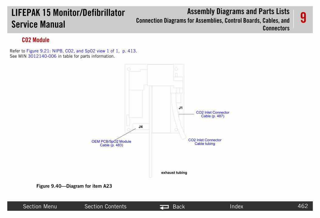
LIFEPAService
bly Diagrams and Parts Listsemblies, Control Boards, Cables, and
Connectors
Secti Index 462
9CO2 M
Connector tubing
Inlet Connector able (p. 487)
Refer to FiguSee MIN 301
K 15 Monitor/Defibrillator Manual
AssemConnection Diagrams for Ass
on Menu Section Contents Back
odule
Figure 9.40—Diagram for item A23
J1
J4
OEM PCB/SpO2 Module Cable (p. 483)
CO2 InletCable
CO2C
exhaust tubing
re 9.21: NIPB, CO2, and Sp02 view 1 of 1, p. 413.2140-006 in table for parts information.

LIFEPAService
bly Diagrams and Parts Listsemblies, Control Boards, Cables, and
Connectors
Secti Index 463
9Powe
Sy
Refer to FigurSee MIN 320
SYS RTS
1234567890123456789012345678901234 34
333231302928272625242322212019181716151413121110987654321
1 P17
PS FAIL*
PWR FAIL*
CHG LEDPWR LED
PWR MONPWR SW*
GND
GNDOEM VPP ENA
ET RXNIBP ON
ET TXOEM RES*
SP TXSP RX
NIBP RXNIBP TX
GND
SYS RX
SYS TX
SYS CTSSYS DTRANALOG ECGGND
GND
SP ET SYNC
PWR RXPWR TX
K 15 Monitor/Defibrillator Manual
AssemConnection Diagrams for Ass
on Menu Section Contents Back
r PCB/System PCB Cable
Figure 9.41—Diagram for item W01
stem PCB (p. 444)
Power PCB (p. 445)
e 9.17: Rear Case view 4 of 7, p. 403.7692-000 in table for parts information.
1111111111222222222233333
P

LIFEPAService
bly Diagrams and Parts Listsemblies, Control Boards, Cables, and
Connectors
Secti Index 464
9Powe
P20
1234
P20
243
UNLD
1
Therapy PCB (p. 446)
Refer to FigurSee MIN 320
K 15 Monitor/Defibrillator Manual
AssemConnection Diagrams for Ass
on Menu Section Contents Back
r PCB/Therapy PCB Cable
Figure 9.42—Diagram for item W02
12
3
4
P08
1234
P08BLGRYERE
GNDSW VBGNDSW VB
Power PCB (p. 445)
e 9.17: Rear Case view 4 of 7, p. 403.7692-000 in table for part information.
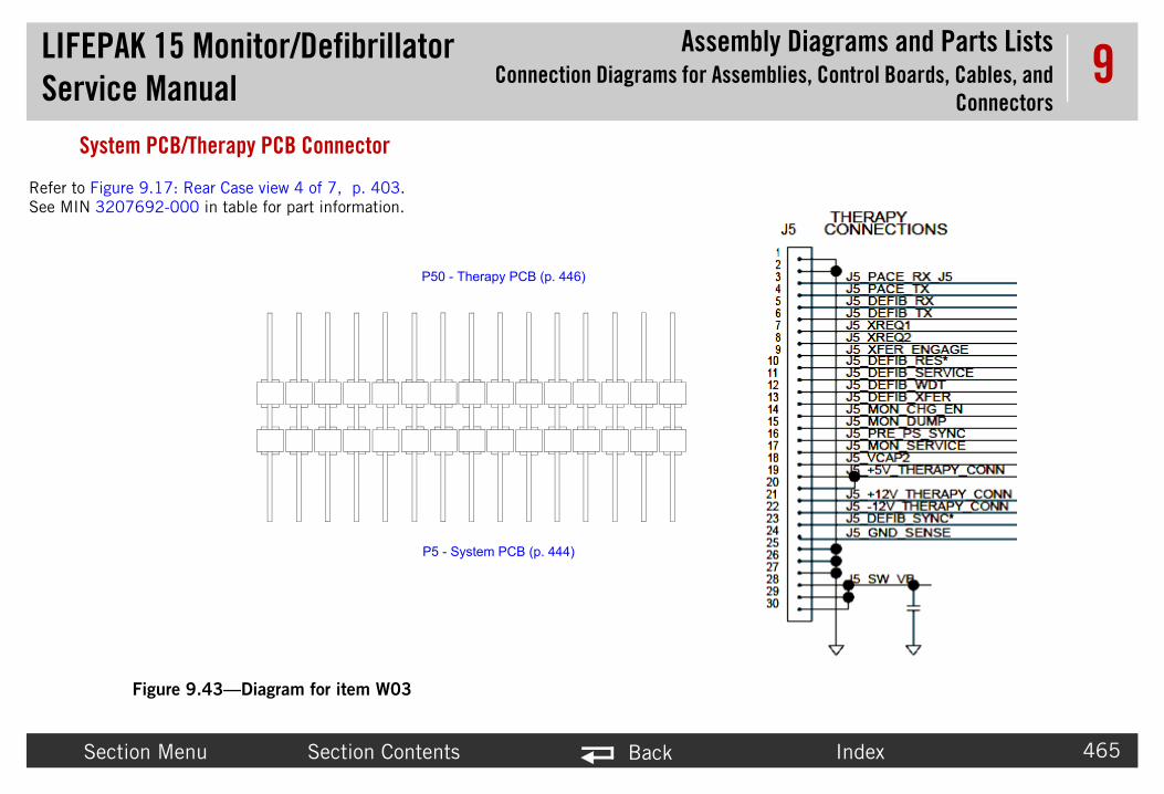
LIFEPAService
bly Diagrams and Parts Listsemblies, Control Boards, Cables, and
Connectors
Secti Index 465
9Syste
Refer to FigurSee MIN 3207
K 15 Monitor/Defibrillator Manual
AssemConnection Diagrams for Ass
on Menu Section Contents Back
m PCB/Therapy PCB Connector
Figure 9.43—Diagram for item W03
P5 - System PCB (p. 444)
P50 - Therapy PCB (p. 446)
e 9.17: Rear Case view 4 of 7, p. 403.692-000 in table for part information.

LIFEPAService
bly Diagrams and Parts Listsemblies, Control Boards, Cables, and
Connectors
Secti Index 466
9Syste
P30
PiInterface PC
K 15 Monitor/Defibrillator Manual
AssemConnection Diagrams for Ass
on Menu Section Contents Back
m PCB/Interface PCB Cable
Figure 9.44—Diagram for item W04
P2
Pin 1n 1System PCB (p. 444)B (p. 447)

LIFEPAService
bly Diagrams and Parts Listsemblies, Control Boards, Cables, and
Connectors
Secti Index 467
9Powe
123456
P42
Contact PCB Module
Refer toCase vieSee MINtable for
K 15 Monitor/Defibrillator Manual
AssemConnection Diagrams for Ass
on Menu Section Contents Back
r PCB/Contact PCB Cable
Figure 9.45—Diagram for item W05
123456
ROW 0COL 0COL 1COL 2COL 3GND
P12
Power PCB (p. 445) Figure 9.17: Rear w 4 of 7, p. 403. 3207261-001 in parts information.
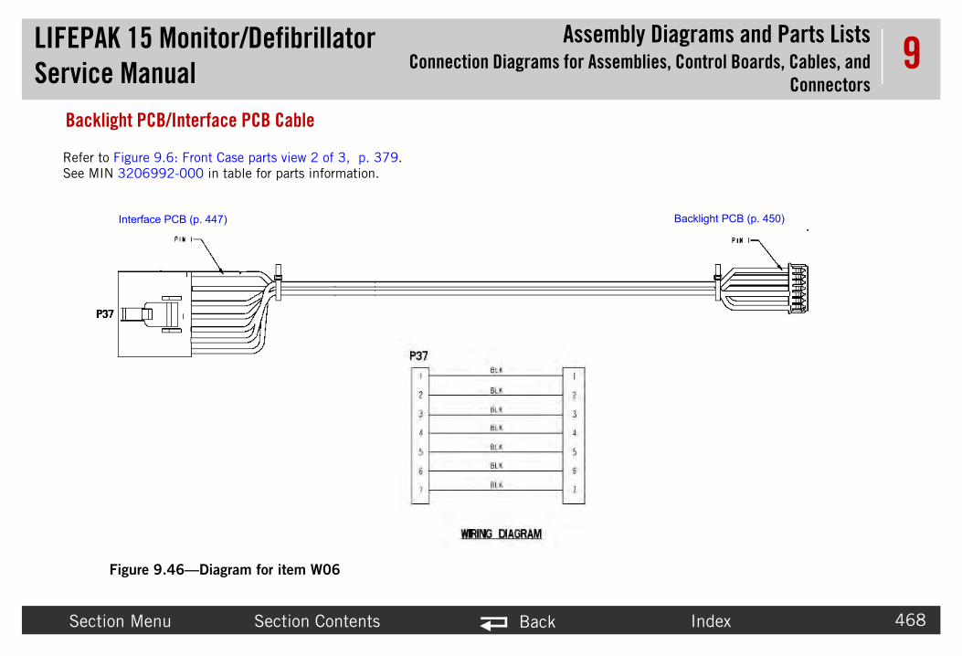
LIFEPAService
bly Diagrams and Parts Listsemblies, Control Boards, Cables, and
Connectors
Secti Index 468
9Backl
Refer toSee MI
P37
Backlight PCB (p. 450)
K 15 Monitor/Defibrillator Manual
AssemConnection Diagrams for Ass
on Menu Section Contents Back
ight PCB/Interface PCB Cable
Figure 9.46—Diagram for item W06
Figure 9.6: Front Case parts view 2 of 3, p. 379.N 3206992-000 in table for parts information.
P49
Pin 1
Interface PCB (p. 447)

LIFEPAService
bly Diagrams and Parts Listsemblies, Control Boards, Cables, and
Connectors
Secti Index 469
9ECG C
E2
DRAIN123456789101112
RLRALALLV1V2V3V4V5V6
CBL
ECGconnector
System
Refer to ParaSee MIN 30
K 15 Monitor/Defibrillator Manual
AssemConnection Diagrams for Ass
on Menu Section Contents Back
onnector Cable
Figure 9.47—Diagram for item W07
BROWNBLACK
RED
YELLOW
BLUE
GRAY
DRAIN
ORANGE
GREEN
VIOLET
WHITE
12
P6
1110987654321
E1
P6
BLACK/RED
E3
PCB (p. 444)
meter Bezel Diagrams and Parts List (p. 392).07991-007 in table for parts information.

LIFEPAService
bly Diagrams and Parts Listsemblies, Control Boards, Cables, and
Connectors
Secti Index 470
9Syste
1234
0
9
P
Pin PIN 1PIN 2
PIN 3
PIN 4
PIN 5 PIN 6
PIN 7
PIN 8
PIN 9
front view
systemconnector
Refer to FigurSee MIN 3009
K 15 Monitor/Defibrillator Manual
AssemConnection Diagrams for Ass
on Menu Section Contents Back
m Connector Cable
Figure 9.48—Diagram for item W08
21
3456789
12345
P1
P
P10
P09
BLU
GRN
YEL
BRN
ORN
GRN/WHT
YEL/GRN
WHT/BLK
E1
in 1
1
GND
SYS TX
SYS RX
SYS DTA
SYS CTS
SYS RTS
GND
ANALOG ECG
SW VB
system
Power PCB (p. 445)
Power PCB (p. 445)
connector
BLU/WHT
e 9.17: Rear Case view 4 of 7, p. 403.652-01 in table for part information.

LIFEPAService
bly Diagrams and Parts Listsemblies, Control Boards, Cables, and
Connectors
Secti Index 471
9Auxili
Refer to FigurSee MIN 3303
K 15 Monitor/Defibrillator Manual
AssemConnection Diagrams for Ass
on Menu Section Contents Back
ary Power Connector Cable (V2)
Figure 9.49—Diagram for item W09
Power PCB (p. 445)
e 9.17: Rear Case view 4 of 7, p. 403.848-002 in table for part information.
Power PCB (p. 445)
J15-A
J15-B
J15-A
J15-B

LIFEPAService
bly Diagrams and Parts Listsemblies, Control Boards, Cables, and
Connectors
Secti Index 472
9Batte
P46
P45
P44
P43
Battery Well 2 +
Battery Well 2 -
Battery Well 1+
Battery Well 1-
21 3
4
P11
P1
P46
P45
ry1-
Battery Well 2-
Battery Well 2+
Power P
Power PCB
Refer to FiguSee MIN 300
P13 connect3009726 cab
The 3303863is installed onV2 with Aux.
K 15 Monitor/Defibrillator Manual
AssemConnection Diagrams for Ass
on Menu Section Contents Back
ry Pins/Power PCB Cable
Figure 9.50—Diagram for item W10
4321
1234
REDGREENBLUEYELLOW
RED/WHTBLUE/WHTGREEN/WHTYELLOW/WHT
P11
P13
3
P44
P43
Battery Well 1+ Batte
Well
CB (p. 445)
(p. 445)
re 9.17: Rear Case view 4 of 7, p. 403.9726-08 or 3303863-000 in table for part information.
or is on the le assembly only.
cable assembly ly in LIFEPAK 15
Power connector.

LIFEPAService
bly Diagrams and Parts Listsemblies, Control Boards, Cables, and
Connectors
Secti Index 473
9Thera
front view
ReferSee M
K 15 Monitor/Defibrillator Manual
AssemConnection Diagrams for Ass
on Menu Section Contents Back
py Connector Cable
Figure 9.51—Diagram for item W11
J23
Transfer Relay Assembly (p. 455)
Therapy PCB (p. 446)
to Figure 9.5: Front Case parts view 1 of 3, p. 378.IN 3207044-002 in table for part information.

LIFEPAService
bly Diagrams and Parts Listsemblies, Control Boards, Cables, and
Connectors
Secti Index 474
9Printe
Refer toSee MIN
P
K 15 Monitor/Defibrillator Manual
AssemConnection Diagrams for Ass
on Menu Section Contents Back
r Control Keypad/Interface PCB Cable
Figure 9.52—Diagram for item W12
Interface PCB (p. 447)
Figure 9.6: Front Case parts view 2 of 3, p. 379. 3206989-000 in table for parts information.
Printer Control Keypad (p. 451)
32 P41

LIFEPAService
bly Diagrams and Parts Listsemblies, Control Boards, Cables, and
Connectors
Secti Index 475
9Main
Interface
Refer to FiguSee MIN 32
P 1234567891011121314151617181920212223242526 26
25242322212019181716151413121110987654321
P39P31
GND
PWR SW*PWR LEDCHG LED
XREQ2
VCCCOL 4COL 3COL 2
SERVICE LED
COL 1
SHOCK LEDGND
SYNC LEDPACING LED
ALARMS LEDNIBP LED
ROW 2ROW 3ROW 4ROW 5COL 0
TRIM LEDANALYZE LEDADVISORY LEDROW 1
K 15 Monitor/Defibrillator Manual
AssemConnection Diagrams for Ass
on Menu Section Contents Back
Keypad/Interface PCB Cable
Figure 9.53—Diagram for item W13
PCB (p. 447) Main Keypad (p. 452)
re 9.6: Front Case parts view 2 of 3, p. 379.07388-001 in table for parts information.
31 P39

LIFEPAService
bly Diagrams and Parts Listsemblies, Control Boards, Cables, and
Connectors
Secti Index 476
9USB F
Refer to FiSee MIN 3
K 15 Monitor/Defibrillator Manual
AssemConnection Diagrams for Ass
on Menu Section Contents Back
lex Assembly
Figure 9.54—Diagram for item W14
System PCB (p. 444)
gure 9.16: Rear Case view 3 of 7, p. 402.206966-001 in table for parts information.

LIFEPAService
bly Diagrams and Parts Listsemblies, Control Boards, Cables, and
Connectors
Secti Index 477
9Speed
Refer to FiSee MIN 3
K 15 Monitor/Defibrillator Manual
AssemConnection Diagrams for Ass
on Menu Section Contents Back
Dial Assembly
Figure 9.55—Diagram for item W15
Interface PCB (p. 447)
gure 9.6: Front Case parts view 2 of 3, p. 379.011128-002 in table for parts information.
P33
654321
P33
ENC ON
ENC0 IN
ENC1 IN
ENC SW1
ENC SW2
GND
selector

LIFEPAService
bly Diagrams and Parts Listsemblies, Control Boards, Cables, and
Connectors
Secti Index 478
9Printe
P4
Pin 1
Printer Asse2625242322212019181716151413121110987654321
NC
InterfacePC
B
EMITTER
ANODE
HEAD TYPE
VHD
VDD
GND
GND
LATCH
MOTOR -
VHD
STB1*
MOTOR +
CHASSIS GNDTHERM 1
CLK
DATA
VSS
GND
GND
STB2*
THERM 2
VHD
CATHODE
COLLECTOR
VHD
Refer to FigurSee MIN 300
K 15 Monitor/Defibrillator Manual
AssemConnection Diagrams for Ass
on Menu Section Contents Back
r Assembly/Interface PCB Cable
Figure 9.56—Diagram for item W16
0P35
Pin 1far sidestripe
Interface PCB (p. 447)
mbly (p. 454)
11421531641751861972082192210231124122513
P40
prin
ter
e 9.7: Front Case parts view 3 of 3, p. 380.9724-001 in table for parts information.
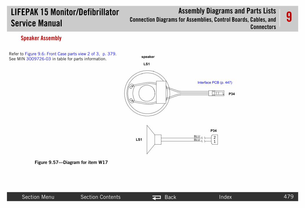
LIFEPAService
bly Diagrams and Parts Listsemblies, Control Boards, Cables, and
Connectors
Secti Index 479
9Speak
21
P34
P34
BLUBLU
Interface PCB (p. 447)
Refer to FiguSee MIN 300
K 15 Monitor/Defibrillator Manual
AssemConnection Diagrams for Ass
on Menu Section Contents Back
er Assembly
Figure 9.57—Diagram for item W17
LS1
LS1
speakerre 9.6: Front Case parts view 2 of 3, p. 379.9726-03 in table for parts information.

LIFEPAService
bly Diagrams and Parts Listsemblies, Control Boards, Cables, and
Connectors
Secti Index 480
9LCD A
LCD(
Refer tSee MI
K 15 Monitor/Defibrillator Manual
AssemConnection Diagrams for Ass
on Menu Section Contents Back
ssembly/Interface PCB Cable
Figure 9.58—Diagram for item W18
Interface PCB (p. 447)
Assembly p. 453)
o Figure 9.6: Front Case parts view 2 of 3, p. 379.N 3206990-001 in table for parts information.

LIFEPAService
bly Diagrams and Parts Listsemblies, Control Boards, Cables, and
Connectors
Secti Index 481
9Printe
chassis ground
Refer toSee MIN
Interface PCB (p. 447)
K 15 Monitor/Defibrillator Manual
AssemConnection Diagrams for Ass
on Menu Section Contents Back
r Assembly/Chassis Ground Cable
Figure 9.59—Diagram for item W19
printerground
Printer Assembly (p. 454)
Figure 9.6: Front Case parts view 2 of 3, p. 379. 3009726-01 in table for parts information.

LIFEPAService
bly Diagrams and Parts Listsemblies, Control Boards, Cables, and
Connectors
Secti Index 482
9Bipha
Biphasic Module (p. 461)
Refer tSee M
P106
K 15 Monitor/Defibrillator Manual
AssemConnection Diagrams for Ass
on Menu Section Contents Back
sic to Therapy PCB Flex Cable
Figure 9.60—Diagram for item W20
o Figure 9.20: Rear Case view 7 of 7, p. 406.IN 3011792-005 in table for part information.
Therapy PCB (p. 446)
P51

LIFEPAService
bly Diagrams and Parts Listsemblies, Control Boards, Cables, and
Connectors
Secti Index 483
9OEM P
odule (p. 458)Refer to Figurp. 413.See MIN 320
K 15 Monitor/Defibrillator Manual
AssemConnection Diagrams for Ass
on Menu Section Contents Back
CB/SpO2 Module Cable
Figure 9.61—Diagram for item W21
SpO2 M
OEM PCB Module (p. 448)
e 9.21: NIPB, CO2, and Sp02 view 1 of 1,
7000-004 in table for parts information.
P26
P3

LIFEPAService
bly Diagrams and Parts Listsemblies, Control Boards, Cables, and
Connectors
Secti Index 484
9SpO2
P1
Refer to PaCO2, and SSee MIN 3
K 15 Monitor/Defibrillator Manual
AssemConnection Diagrams for Ass
on Menu Section Contents Back
Connector Cable
Figure 9.62—Diagram for item W22
SpO2 Module (p. 458)
rameter Bezel Diagrams and Parts List (p. 392) and NIPB, p02 view 1 of 1 (p. 413)
207000-004 in table for parts information.

LIFEPAService
bly Diagrams and Parts Listsemblies, Control Boards, Cables, and
Connectors
Secti Index 485
9OEM P
CO2 MPin Pin 1
OEM PCB Module (p. 448)
Refer toSee MI
K 15 Monitor/Defibrillator Manual
AssemConnection Diagrams for Ass
on Menu Section Contents Back
CB/CO2 Module Cable
Figure 9.63—Diagram for item W26
odule (p. 462) 1
NIPB, CO2, and Sp02 (p. 413).N 3206998-002 in table for part information.

LIFEPAService
bly Diagrams and Parts Listsemblies, Control Boards, Cables, and
Connectors
Secti Index 486
9OEM P
P2V+V+
X
EYND
NDV+
ND
XIBP RES
123456789
10
IBP Module (p. 460)
P2
Pin 1
Refer toSee MI
K 15 Monitor/Defibrillator Manual
AssemConnection Diagrams for Ass
on Menu Section Contents Back
CB/NIBP Module Cable
Figure 9.64—Diagram for item W27
12345678910
P286V+6V+
TX
KEYGND
GND6V+
GND
RXNIBP_RES (Ext Reset)
66
T
KG
G6
G
RN
NOEM PCB Module (p. 448)
P28
Pin 1
NIPB, CO2, and Sp02 (p. 413).N 3012181-00 in table for part information.

LIFEPAService
bly Diagrams and Parts Listsemblies, Control Boards, Cables, and
Connectors
Secti Index 487
9CO2 I
Refer to(optionSee MI
K 15 Monitor/Defibrillator Manual
AssemConnection Diagrams for Ass
on Menu Section Contents Back
nlet Connector Cable
Figure 9.65—Diagram for item W28
CO2 tubing
CO2 Module Adapter Cable (p. 488)
Figure 9.11: Parameter Bezel view 2 of 4 al CO2 and NIBP), p. 393.N 3012140-008 in table for part information.

LIFEPAService
bly Diagrams and Parts Listsemblies, Control Boards, Cables, and
Connectors
Secti Index 488
9CO2 M
CO2 Module (p. 462)
K 15 Monitor/Defibrillator Manual
AssemConnection Diagrams for Ass
on Menu Section Contents Back
odule Adapter Cable
Figure 9.66—Diagram for item W30
CO2 Inlet Connector Cable (p. 487)

LIFEPAService
bly Diagrams and Parts Listsemblies, Control Boards, Cables, and
Connectors
Secti Index 489
9Invas
System P
Refer to Figu(optional invSee MIN 32
K 15 Monitor/Defibrillator Manual
AssemConnection Diagrams for Ass
on Menu Section Contents Back
ive Pressure Assembly
Figure 9.67—Diagram for item W33
CB (p. 444)
re 9.12: Parameter Bezel view 3 of 4 asive pressure), p. 394.00466-01 in table for parts information.

LIFEPAService
bly Diagrams and Parts Listsemblies, Control Boards, Cables, and
Connectors
Secti Index 490
9Tempe
Refer to Figu(optional temSee MIN 33
B (p. 444)
P7
K 15 Monitor/Defibrillator Manual
AssemConnection Diagrams for Ass
on Menu Section Contents Back
rature Connector Cable Assembly
Figure 9.68—Diagram for item W35
re 9.13: Parameter Bezel view 4 of 4 perature cable assembly), p. 395.
03936-001 in table for parts information.
P7
System PC

LIFEPAService
bly Diagrams and Parts ListsRepair Kits
Secti Index 491
9Repair KitsThe repair kit
Due to the ne rtially assembled from the factory.
Table
Repai
NIBP
NIBP
Invasi
CO2 M
OEM P
Interfa
Power
System
Therap
Therap
ECG C
Bipha
Backli
K 15 Monitor/Defibrillator Manual
Assem
on Menu Section Contents Back
s include components that support a particular replacement activity.
ed for special tooling and processes, the front and rear case repair kits come pa
9.16—Repair Kits List
r Kit
MAXIQ 5.2 Repair Kit (MIN 3305431-531) (p. 494)
Module Repair Kit (MIN 3305431-000) (p. 495)
ve Pressure Connector Repair Kit (MIN 3305431-001) (p. 496)
odule Repair Kit (MIN 3305431-002) (p. 497)
CBA Repair Kit, V1 (MIN 3305431-004) (p. 498)
ce PCBA Repair Kit, V1 (MIN 3305431-005) (p. 499)
PCBA Repair Kit, V1 (MIN 3305431-006) (p. 500)
PCBA Repair Kit, V1 (MIN 3305431-007) (p. 501)
y PCBA Repair Kit (MIN 3305431-008) (p. 502)
y Connector Repair Kit (MIN 3305431-009) (p. 503)
onnector Repair Kit (MIN 3305431-010) (p. 503)
sic Module Repair Kit (MIN 3305431-011) (p. 504)
ght Inverter Repair Kit (MIN 3305431-012) (p. 505)

LIFEPAService
bly Diagrams and Parts ListsRepair Kits
Secti Index 492
9
Displa
CO2 C
Intern
Extern
Paddl
Displa
Guard
Handl
NIBP
Front
Rear C
MASIM
MASIM
Tempe
OEM P
Interfa
Table
Repai
K 15 Monitor/Defibrillator Manual
Assem
on Menu Section Contents Back
y Repair Kit (MIN 3305431-013) (p. 505)
onnector Repair Kit (MIN 3305431-014) (p. 506)
al Hardware Repair Kit (MIN 3305431-015) (p. 507)
al Hardware Repair Kit (MIN 3305431-016) (p. 507)
e Retainer Repair Kit (MIN 3305431-017) (p. 508)
y Shield Repair Kit (MIN 3305431-018) (p. 508)
& Feet Repair Kit (MIN 3305431-019) (p. 509)
e Repair Kit (MIN 3305431-020) (p. 509)
Connector Repair Kit (MIN 3305431-022) (p. 510)
Case Repair Kit (MIN 3305431-023) (p. 511)
ase Repair Kit (MIN 3305431-024) (p. 512)
O Sp02 Module Repair Kit (MIN 3305431-025) (p. 513)
O Sp02 Panel Mount Cable Repair Kit (MIN 3305431-026) (p. 514)
rature Cable Repair Kit (MIN 3305431-027) (p. 515)
CBA Repair Kit, V2 (MIN 3305431-028) (p. 516)
ce PCBA Repair Kit, V2 (MIN 3305431-029) (p. 517)
9.16—Repair Kits List (Continued)
r Kit

LIFEPAService
bly Diagrams and Parts ListsRepair Kits
Secti Index 493
9
Power
System
Table
Repai
K 15 Monitor/Defibrillator Manual
Assem
on Menu Section Contents Back
PCBA Repair Kit, V2 (MIN 3305431-030) (p. 518)
PCBA Repair Kit (MIN 3305431-031) (p. 519)
9.16—Repair Kits List (Continued)
r Kit

LIFEPAService
bly Diagrams and Parts ListsRepair Kits
Secti Index 494
9NIBP Table
MIN
33179
20225
20225
32073
30108
32073
20140
20225
K 15 Monitor/Defibrillator Manual
Assem
on Menu Section Contents Back
MAXIQ 5.2 Repair Kit (MIN 3305431-531)9.17—NIBP Module Repair Kit Parts
Description Notes
65-002 MODULE, NIBP, MAXIQ, ROHS
3-760 SCREW-M, PH, NYLOK, CS, 4-40, .250L
3-761 SCREW-M, CS, Z, PH, NYLOCK, 4-40 X .312L
37-312 SCREW-MACH, PNH, PHH, NYLOCK, 4-40, 0.312L, WSHR, CS, ZN
05-000 SOCKET RETAINER CLIP - 10 PIN
61-375 SCREW, CAP SCH, TORX, 6-32 X .375L, SS
7-069 SCREW- 6-32 X .375
3-763 SCREW-M PH, NYLOK 4-40 X .437

LIFEPAService
bly Diagrams and Parts ListsRepair Kits
Secti Index 495
9NIBP Table
MIN
32062
20225
20225
32073
30108
32073
20140
20225
K 15 Monitor/Defibrillator Manual
Assem
on Menu Section Contents Back
Module Repair Kit (MIN 3305431-000)9.18—NIBP Module Repair Kit Parts
Description Notes
68-011 MODULE, NIBP, NONINVASIVE BP, ND+ ROHS
3-760 SCREW-M, PH, NYLOK, CS, 4-40, .250L
3-761 SCREW-M, CS, Z, PH, NYLOCK, 4-40 X .312L
37-312 SCREW-MACH, PNH, PHH, NYLOCK, 4-40, 0.312L, WSHR, CS, ZN
05-000 SOCKET RETAINER CLIP - 10 PIN
61-375 SCREW, CAP SCH, TORX, 6-32 X .375L, SS
7-069 SCREW- 6-32 X .375
3-763 SCREW-M PH, NYLOK 4-40 X .437

LIFEPAService
bly Diagrams and Parts ListsRepair Kits
Secti Index 496
9InvasTable
MIN
32004
30079
32073
32073
20140
20225
K 15 Monitor/Defibrillator Manual
Assem
on Menu Section Contents Back
ive Pressure Connector Repair Kit (MIN 3305431-001)9.19—IP Connector Repair Kit Parts List
Description Notes
66 WIRE HARNESS-INVASIVE PRESSURE 1 / 2
98 GASKET-CONNECTOR, INVASIVE PRESSURE
37-312 SCREW-MACH, PNH, PHH, NYLOCK, 4-40, 0.312L, WSHR, CS, ZN
61-375 SCREW, CAP SCH, TORX, 6-32 X .375L, SS
7-069 SCREW- 6-32 X .375
3-763 SCREW-M PH, NYLOK 4-40 X .437

LIFEPAService
bly Diagrams and Parts ListsRepair Kits
Secti Index 497
9CO2 MTable
MIN
30121
20225
20225
32073
30108
32073
20140
20225
K 15 Monitor/Defibrillator Manual
Assem
on Menu Section Contents Back
odule Repair Kit (MIN 3305431-002)9.20—C02 Module Parts List
Description Notes
40 MODULE, CO2, MINI
3-760 SCREW-M, PH, NYLOK, CS, 4-40, .250L
3-761 SCREW-M, CS, Z, PH, NYLOCK, 4-40 X .312L
37-312 SCREW-MACH, PNH, PHH, NYLOCK, 4-40, 0.312L, WSHR, CS, ZN
05-000 SOCKET RETAINER CLIP - 10 PIN
61-375 SCREW, CAP SCH, TORX, 6-32 X .375L, SS
7-069 SCREW- 6-32 X .375
3-763 SCREW-M PH, NYLOK 4-40 X .437

LIFEPAService
bly Diagrams and Parts ListsRepair Kits
Secti Index 498
9OEM PTable
MIN
32068
20225
32073
30108
32073
20140
20225
32069
K 15 Monitor/Defibrillator Manual
Assem
on Menu Section Contents Back
CBA Repair Kit, V1 (MIN 3305431-004)9.21—OEM PCBA Repair Kit Parts List
Description Notes
13 PCB ASSY - OEM, LIFEPAK15
3-761 SCREW-M,CS, Z, PH, NYLOCK, 4-40 X .312L
37-312 SCREW-MACH, PNH, PHH, NYLOCK, 4-40, 0.312L, WSHR, CS, ZN
05-000 SOCKET RETAINER CLIP - 10 PIN
61-375 SCREW, CAP SCH, TORX, 6-32 X .375L, SS
7-069 SCREW- 6-32 X .375
3-763 SCREW-M PH, NYLOK 4-40 X .437
91 CABLE ASSY—FLEX, SYSTEM PCB/INTERFACE PCB

LIFEPAService
bly Diagrams and Parts ListsRepair Kits
Secti Index 499
9InterfTable
MIN
32068
20225
32073
20140
20225
K 15 Monitor/Defibrillator Manual
Assem
on Menu Section Contents Back
ace PCBA Repair Kit, V1 (MIN 3305431-005)9.22—Interface PCBA Repair Kit Parts List
Description Notes
15 PCB ASSY - INTERFACE, LIFEPAK15
3-761 SCREW-M, CS, Z, PH, NYLOCK, 4-40 X .312L
61-375 SCREW, CAP SCH, TORX, 6-32 X .375L, SS
7-069 SCREW- 6-32 X .375
3-763 SCREW-M PH, NYLOK 4-40 X .437

LIFEPAService
bly Diagrams and Parts ListsRepair Kits
Secti Index 500
9PoweTable
MIN
32067
20225
32073
30108
32073
20140
20225
K 15 Monitor/Defibrillator Manual
Assem
on Menu Section Contents Back
r PCBA Repair Kit, V1 (MIN 3305431-006)9.23—Power PCBA Repair Kit Parts List
Description Notes
49 PCB ASSY - POWER, LIFEPAK15
3-761 SCREW-M, CS, Z, PH, NYLOCK, 4-40 X .312L
37-312 SCREW-MACH, PNH, PHH, NYLOCK, 4-40, 0.312L, WSHR, CS, ZN
05-000 SOCKET RETAINER CLIP - 10 PIN
61-375 SCREW, CAP SCH, TORX, 6-32 X .375L, SS
7-069 SCREW- 6-32 X .375
3-763 SCREW-M PH, NYLOK 4-40 X .437

LIFEPAService
bly Diagrams and Parts ListsRepair Kits
Secti Index 501
9SysteTable
MIN
32068
30098
30116
20225
32073
30108
32073
20140
20225
30119
30116
K 15 Monitor/Defibrillator Manual
Assem
on Menu Section Contents Back
m PCBA Repair Kit, V1 (MIN 3305431-007)9.24—System PCBA Repair Kit Parts List
Description Notes
34 PCB ASSY - SYSTEM, LIFEPAK15
78 CONN-HDR, SQUARE PIN DUAL ROW, 30 PIN
30-00 SPACER-PCB
3-761 SCREW-M, CS, Z, PH, NYLOCK, 4-40 X .312L
37-312 SCREW-MACH, PNH, PHH, NYLOCK, 4-40, 0.312L, WSHR, CS, ZN
05-000 SOCKET RETAINER CLIP - 10 PIN
61-375 SCREW, CAP SCH, TORX, 6-32 X .375L, SS
7-069 SCREW- 6-32 X .375
3-763 SCREW-M PH, NYLOK 4-40 X .437
80-00 LABEL, SHOCK HAZARD
29 INSERT—HEX, LP12

LIFEPAService
bly Diagrams and Parts ListsRepair Kits
Secti Index 502
9TheraTable
MIN
33063
30116
20225
20225
32073
30108
32073
20140
20225
30116
K 15 Monitor/Defibrillator Manual
Assem
on Menu Section Contents Back
py PCBA Repair Kit (MIN 3305431-008)9.25—Therapy PCBA Repair Kit Parts List
Description Notes
11 PCB ASSY - THERAPY, LIFEPAK15
29-00 INSERT-HEX,LIFEPAK15
3-550 SCREW-PH, NYLOCK, PHIL, SS, #4-40 X 1.125L
3-761 SCREW-M,CS,Z,PH, NYLOCK, 4-40 X .312L
37-312 SCREW-MACH, PNH, PHH, NYLOCK, 4-40, 0.312L, WSHR, CS, ZN
05-000 SOCKET RETAINER CLIP - 10 PIN
61-375 SCREW, CAP SCH, TORX, 6-32 X .375L, SS
7-069 SCREW- 6-32 X .375
3-763 SCREW-M PH, NYLOK 4-40 X .437
30 SPACER—PCB, LP12

LIFEPAService
bly Diagrams and Parts ListsRepair Kits
Secti Index 503
9Thera
ECG C
Table
MIN
32070
32077
32073
20140
Table
MIN
30079
80591
32073
20140
20225
K 15 Monitor/Defibrillator Manual
Assem
on Menu Section Contents Back
py Connector Repair Kit (MIN 3305431-009)
onnector Repair Kit (MIN 3305431-010)
9.26—Therapy Connector Repair Kit Parts List
Description Notes
44 THERAPY CONN
01 GASKET
61-375 SCREW, CAP SCH, TORX, 6-32 X .375L, SS
7-069 SCREW- 6-32 X .375
9.27—Hypertronics ECG Connector Repair Kit Parts List
Description Notes
91 ECG CABLE
5 GASKET
61-375 SCREW, CAP SCH, TORX, 6-32 X .375L, SS
7-069 SCREW- 6-32 X .375
3-763 SCREW-M PH, NYLOK 4-40 X .437

LIFEPAService
bly Diagrams and Parts ListsRepair Kits
Secti Index 504
9BiphaTable
MIN
30101
20053
20225
32073
32073
20140
20225
K 15 Monitor/Defibrillator Manual
Assem
on Menu Section Contents Back
sic Module Repair Kit (MIN 3305431-011)9.28—Biphasic Module Repair Kit Parts List
Description Notes
78 PCB ASSY - BIPHASIC MODULE, LIFEPAK15
6-001 CABLE TIES, SM
3-761 SCREW-M, CS, Z, PH, NYLOCK, 4-40 X .312L
37-312 SCREW-MACH, PNH, PHH, NYLOCK, 4-40, 0.312L, WSHR, CS, ZN
61-375 SCREW, CAP SCH, TORX, 6-32 X .375L, SS
7-069 SCREW- 6-32 X .375
3-763 SCREW-M PH, NYLOK 4-40 X .437

LIFEPAService
bly Diagrams and Parts ListsRepair Kits
Secti Index 505
9Backl
Displa
Table
MIN
32079
20225
32073
20140
20225
Table
MIN
32032
20225
20225
32073
20140
20225
K 15 Monitor/Defibrillator Manual
Assem
on Menu Section Contents Back
ight Inverter Repair Kit (MIN 3305431-012)
y Repair Kit (MIN 3305431-013)
9.29—Backlight Inverter Repair Kit Parts List
Description Notes
33 BACKLIGHT
3-761 SCREW-M, CS, Z, PH, NYLOCK, 4-40 X .312L
61-375 SCREW, CAP SCH, TORX, 6-32 X .375L, SS
7-069 SCREW- 6-32 X .375
3-763 SCREW-M PH, NYLOK 4-40 X .437
9.30—Display Repair Kit Parts List
Description Notes
21 DISPLAY
3-764 SCREW, MACHINE, PANHEAD, NYLOK, 4-40 X .500
3-761 SCREW-M, CS, Z, PH, NYLOK, 4-40 X .312L
61-375 SCREW, CAP SCH, TORX, 6-32 X .375L, SS
7-069 SCREW- 6-32 X .375
3-763 SCREW-M PH, NYLOK 4-40 X .437

LIFEPAService
bly Diagrams and Parts ListsRepair Kits
Secti Index 506
9CO2 CTable
MIN
30121
30121
30079
30121
20225
30121
32073
20140
20225
K 15 Monitor/Defibrillator Manual
Assem
on Menu Section Contents Back
onnector Repair Kit (MIN 3305431-014)9.31—CO2 Connector Repair Kit Parts List
Description Notes
40-008 FRS ASSEMBLY-CO2, MINI-MODULE, LIFEPAK15
21 RETAINER-CO2 CONN
97 SEAL-CO2 CONNECTOR
19 ADAPTER-CO2 CONNECTOR
3-732 SCREW-MACH, NYLOK, PNH, PHH, 2-56 X .500, CS, ZN
20 CO2 CONNECTOR COVER
61-375 SCREW, CAP SCH, TORX, 6-32 X .375L, SS
7-069 SCREW- 6-32 X .375
3-763 SCREW-M PH, NYLOK 4-40 X .437

LIFEPAService
bly Diagrams and Parts ListsRepair Kits
Secti Index 507
9Intern
Extern
Table
MIN
20225
32073
30108
Table
MIN
32073
20140
20225
K 15 Monitor/Defibrillator Manual
Assem
on Menu Section Contents Back
al Hardware Repair Kit (MIN 3305431-015)
al Hardware Repair Kit (MIN 3305431-016)
9.32—Internal Hardware Repair Kit Parts List
Description Notes
3-761 SCREW-M, CS, Z, PH, NYLOCK, 4-40 X .312L
37-312 SCREW-MACH, PNH, PHH, NYLOCK, 4-40, 0.312L, WSHR, CS, ZN
05-000 SOCKET RETAINER CLIP - 10 PIN
9.33—External Hardware Repair Kit Parts List
Description Notes
61-375 SCREW, CAP SCH, TORX, 6-32 X .375L, SS
7-069 SCREW- 6-32 X .375
3-763 SCREW-M PH, NYLOK 4-40 X .437

LIFEPAService
bly Diagrams and Parts ListsRepair Kits
Secti Index 508
9Paddl
Displa
Table
MIN
30067
20140
32073
Table
MIN
33054
32073
K 15 Monitor/Defibrillator Manual
Assem
on Menu Section Contents Back
e Retainer Repair Kit (MIN 3305431-017)
y Shield Repair Kit (MIN 3305431-018)
9.34—Paddle Retainer Repair Kit Parts List
Description Notes
66 COVER-LATCH, PADDLE
7-069 SCREW- 6-32 X .375
18 LABEL SET, ENGLISH
9.35—Display Shield Repair Kit Parts List
Description Notes*
27-000 ASSEMBLY, DISPLAY SHIELD
67-312 SCREW, T10 TORX, 4-40 X .312

LIFEPAService
bly Diagrams and Parts ListsRepair Kits
Secti Index 509
9Guard
Handl
Table
MIN
32072
32069
32073
32073
Table
MIN
32077
32077
32077
20140
K 15 Monitor/Defibrillator Manual
Assem
on Menu Section Contents Back
& Feet Repair Kit (MIN 3305431-019)
e Repair Kit (MIN 3305431-020)
9.36—Guard & Feet Repair Kit Parts List
Description Notes
47 FOOT-MOUNTING
68 GUARD, CORNER LOWER LEFT
07 GUARD, LOWER RIGHT
61-375 SCREW, CAP SCH, TORX, 6-32 X .375L, SS
9.37—Handle Repair Kit Parts List
Description Notes
06 HANDLE
07 HANDLE COVER PLATE, LEFT
46 HANDLE COVER PLATE, RIGHT
7-069 SCREW- 6-32 X .375

LIFEPAService
bly Diagrams and Parts ListsRepair Kits
Secti Index 510
9NIBP Table
MIN
32070
32073
20140
20225
K 15 Monitor/Defibrillator Manual
Assem
on Menu Section Contents Back
Connector Repair Kit (MIN 3305431-022)9.38—NIBP Connector Repair Kit Parts List
Description Notes
33 PNEUMATIC COUPLER
61-375 SCREW, CAP SCH, TORX, 6-32 X .375L, SS
7-069 SCREW- 6-32 X .375
3-763 SCREW-M PH, NYLOK 4-40 X .437

LIFEPAService
bly Diagrams and Parts ListsRepair Kits
Secti Index 511
9FrontTable
MIN
32077
32067
32080
80423
20225
20225
32073
20140
20225
32077
32073
K 15 Monitor/Defibrillator Manual
Assem
on Menu Section Contents Back
Case Repair Kit (MIN 3305431-023)9.39—Front Case Repair Kit Parts List
Description Notes
25 ASSY - ENCLOSURE, FRONT
24 LENS - DISPLAY
03 LABEL - PHYSIO-CONTROL ICON
4 SEAL - PERIMETER, CASE
3-764 SCREW, MACHINE, PANHEAD, NYLOK, 4-40 X .500
3-761 SCREW-M, CS, Z, PH, NYLOCK, 4-40 X .312L
61-375 SCREW, CAP SCH, TORX, 6-32 X .375L, SS
7-069 SCREW- 6-32 X .375
3-763 SCREW-M PH, NYLOK 4-40 X .437
01 SEAL—THERAPY CONNECTOR
67 SCREW—MACHINE, TRH, T10 TORX (R), 4-40, SS

LIFEPAService
bly Diagrams and Parts ListsRepair Kits
Secti Index 512
9Rear Table
MIN
32077
32069
20006
80227
20053
20053
20225
20140
20225
32073
32073
30108
K 15 Monitor/Defibrillator Manual
Assem
on Menu Section Contents Back
Case Repair Kit (MIN 3305431-024)9.40—Rear Case Repair Kit Parts List
Description Notes
26 ASSY - ENCLOSURE, REAR
60 FLEXIBLE GROUND PLANE - EMI SHIELD
0 AUX/SERIAL CONNECTOR O-RINGS
8 BANANA PINS
6 TIE WRAP, LG
6 CABLE TIES, SM
3-761 SCREW-M, CS, Z, PH, NYLOCK, 4-40 X .312L
7-069 SCREW- 6-32 X .375
3-763 SCREW-M PH, NYLOK 4-40 X .437
61-375 SCREW, CAP SCH, TORX, 6-32 X .375L, SS
37-312 SCREW-MACH, PNH, PHH, NYLOCK, 4-40, 0.312L, WSHR, CS, ZN
05-000 SOCKET RETAINER CLIP - 10 PIN

LIFEPAService
bly Diagrams and Parts ListsRepair Kits
Secti Index 513
9MASIMTable
MIN
20225
32070
20140
32073
30108
32073
K 15 Monitor/Defibrillator Manual
Assem
on Menu Section Contents Back
O Sp02 Module Repair Kit (MIN 3305431-025)9.41—MASIMO Sp02 Module Parts List
Description Notes
3-760 SCREW-M, PH, NYLOK, CS, 4-40
34 MODULE-OEM, PULSE OXIMETER, MX-1
7 SCREW—PANHEAD, PHILLIPS, STAINLESS STEEL, SELF-SEALING, SELF-LOCKING
61 SCREW—CAP, SCH, REC T15 TORX 6-32, 0.375L, SS, NYLOK
05 SOCKET—RETAINER CLIP
37 SCREW—MACHINE, PNH, PHH, 4-40, NYLOK, CS, WITH WASHER
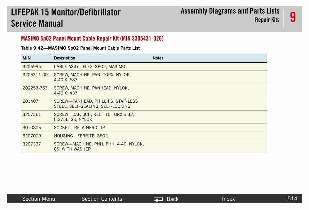
LIFEPAService
bly Diagrams and Parts ListsRepair Kits
Secti Index 514
9MASIMTable
MIN
32069
32053
20225
20140
32073
30108
32070
32073
K 15 Monitor/Defibrillator Manual
Assem
on Menu Section Contents Back
O Sp02 Panel Mount Cable Repair Kit (MIN 3305431-026)9.42—MASIMO Sp02 Panel Mount Cable Parts List
Description Notes
95 CABLE ASSY - FLEX, SPO2, MASIMO
11-001 SCREW, MACHINE, PAN, TORX, NYLOK, 4-40 X .687
3-763 SCREW, MACHINE, PANHEAD, NYLOK, 4-40 X .437
7 SCREW—PANHEAD, PHILLIPS, STAINLESS STEEL, SELF-SEALING, SELF-LOCKING
61 SCREW—CAP, SCH, REC T15 TORX 6-32, 0.375L, SS, NYLOK
05 SOCKET—RETAINER CLIP
09 HOUSING—FERRITE, SPO2
37 SCREW—MACHINE, PNH, PHH, 4-40, NYLOK, CS, WITH WASHER

LIFEPAService
bly Diagrams and Parts ListsRepair Kits
Secti Index 515
9TempeTable
MIN
32076
20140
20225
32073
33039
30079
K 15 Monitor/Defibrillator Manual
Assem
on Menu Section Contents Back
rature Cable Repair Kit (MIN 3305431-027)9.43—Temperature Cable Repair Kit Parts List
Description Notes
31-375 SCREW, CAP, SCH, REC T15 TORX 6-32, 0.375L, SS, NYLOK
7-069 SCREW, SELF-SEAL, SELF-LOCK, 6-32 X 0.375
3-763 SCREW, MACHINE, PANHEAD, NYLOK, 4-40 X .437
37-312 SCREW, MACH, PNH, PHH, NYLOCK, 4-40, 0.312L, WSHR, CS, ZN
36-001 CABLE ASSEMBLY - TEMPERATURE
98-00 GASKET-CONNECTOR, INVASIVE PRESSURE

LIFEPAService
bly Diagrams and Parts ListsRepair Kits
Secti Index 516
9OEM P
Table
MIN
32073
32073
30108
20225
20225
20140
33063
K 15 Monitor/Defibrillator Manual
Assem
on Menu Section Contents Back
CBA Repair Kit, V2 (MIN 3305431-028)
9.44—V2 OEM PCBA Repair Kit Parts List
Description Notes
61-375 SCREW, CAP, SCH, REC T15 TORX 6-32, 0.375L, SS, NYLOK
37-312 SCREW, MACH ,PNH, PHH, NYLOCK, 4-40, 0.312L, WSHR, CS, ZN
05-000 SOCKET RETAINER CLIP—10 PIN
3-763 SCREW, MACH, PANHEAD, NYLOK, 4-40 X .437
3-761 SCREW-M, CS, Z, PH, NYLOCK, 4-40 X .312L
7-069 SCREW, SELF-SEAL, SELF-LOCK, 6-32 X 0.375
08-000 PCB ASSY - OEM

LIFEPAService
bly Diagrams and Parts ListsRepair Kits
Secti Index 517
9Interf
Table
MIN
33063
32073
32069
20225
20140
K 15 Monitor/Defibrillator Manual
Assem
on Menu Section Contents Back
ace PCBA Repair Kit, V2 (MIN 3305431-029)
9.45—V2 Interface PCBA Repair Kit Parts List
Description Notes
67-000 PCB ASSY—INTERFACE, LP15 V2
61-375 SCREW, CAP, SCH, REC T15 TORX 6-32, 0.375L, SS, NYLOK
91-003 CABLE ASSY—FLEX, SYSTEM PCB/INTERFACE PCB
3-761 SCREW-M, CS, Z, PH, NYLOCK, 4-40 X .312L
7-069 SCREW, SELF-SEAL, SELF-LOCK, 6-32 X 0.375

LIFEPAService
bly Diagrams and Parts ListsRepair Kits
Secti Index 518
9PoweTable
MIN
33025
32073
32073
30108
20225
20225
20140
K 15 Monitor/Defibrillator Manual
Assem
on Menu Section Contents Back
r PCBA Repair Kit, V2 (MIN 3305431-030)9.46—V2 Power PCBA Repair Kit Parts List
Description Notes
19-002 PCB ASSY—POWER, LP15
61-375 SCREW-CAP, SCH, REC T15 TORX 6-32, 0.375L, SS, NYLOK
37-312 SCREW, MACH, PNH, PHH, NYLOCK, 4-40, 0.312L, WSHR, CS, ZN
05-000 SOCKET RETAINER CLIP—10 PIN
3-763 SCREW, MACH, PANHEAD, NYLOK, 4-40 X .437
3-761 SCREW-M, CS, Z, PH, NYLOCK, 4-40 X .312L
7-069 SCREW, SELF-SEAL, SELF-LOCK, 6-32 X 0.375

LIFEPAService
bly Diagrams and Parts ListsRepair Kits
Secti Index 519
9SysteTable
MIN
30098
30116
20225
32073
30108
32073
20140
30116
32068
33060
33060
33060
K 15 Monitor/Defibrillator Manual
Assem
on Menu Section Contents Back
m PCBA Repair Kit (MIN 3305431-031)9.47—System PCBA Repair Kit Parts List
Description Notes
78 CONNECTOR—HDR, SQUARE PIN, DUAL ROW, 24 PIN
30 SPACER—PCB, LP12
3 SCREW—MACHINE, PANHEAD, NYLOK
37 SCREW—MACHINE, PNH, PHH, 4-40, NYLOCK, CS, WITH WASHER
05 SOCKET—RETAINER CLIP
61 SCREW—CAP, SCH, REC T15 TORX 6-32, 0.375L, SS, NYLOK
7 SCREW—PANHEAD, PHILLIPS, STAINLESS STEEL, SELF-SEALING, SELF-LOCKING
29 INSERT—HEX, LP15
34 PCB ASSY—SYSTEM, LP15
20 INSULATOR—SYSTEM PCB, CENTER
21 INSULATOR—SYSTEM PCB, RIGHT
22 INSULATOR—SYSTEM PCB, LEFT

LIFEPAService
bly Diagrams and Parts ListsRepair Kits
Secti Index 520
9
80444
30119
Table
MIN
K 15 Monitor/Defibrillator Manual
Assem
on Menu Section Contents Back
7 SPACER—FOAM
80 LABEL—SHOCK HAZARD
9.47—System PCBA Repair Kit Parts List (Continued)
Description Notes

LIFEPAService
bly Diagrams and Parts Listsator Part Number and Serial Number
Secti Index 521
9Defibrillato
PN anThe LI ted on a label on the rear case assembly in Batter
UnderThe de tures, and language.
UnderThe se r created during device manufacturing and appea order parts.
Splash/dust pro
Ca
8-digit se
10-c
Yea
K 15 Monitor/Defibrillator Manual
AssemDefibrill
on Menu Section Contents Back
r Part Number and Serial Number
d SN LabelFEPAK 15 monitor/defibrillator serial number (SN) and part number (PN) are noy Well 1.
standing the Part Numbervice part number, for example, V15-2-000014, reflects the device options, fea
standing the Serial Numberrial number for the LIFEPAK 15 monitor/defibrillator is related to the sales orders on the serial number label in Battery Well 1. Use this number when calling to
LIFEPAK 15IP44 2009
V15-2-000014
34658213
Conforms to Medical Device Directive
93/42/EEC
of per IEC 60529
talog number
rial number
haracter PN
Do not dispose in unsorted waste stream
CSA certification for Canada and the United States
Physio-Control, INC.11811 Willows Rd. NE, Redmond, WA 98052Made in U.S.A
r of manufacture
0123
PN
SN
REF 99577-000001
Patent Information area

LIFEPAService
bly Diagrams and Parts ListsOrdering Parts
Secti Index 522
9Ordering PTo order parts at 1.800.442.1142. Provide the part number and serial numbe Ns, reference designations, and descriptions. Parts may be subst
ManuIn som The date of manufacture is available by access
SerialThe se used in producing your device. When orderin
K 15 Monitor/Defibrillator Manual
Assem
on Menu Section Contents Back
arts, contact your local Physio-Control representative. In the USA, call PARTSLINE™
r located on the device label in Battery Well 1. Specify all assembly numbers, MIituted to reflect device modifications and improvements.
facturing Datee cases when ordering parts, you may also need the device manufacturing date.ing the Service/Status/Device Data as described in Device Data (p. 110).
Numberrial number of the device identifies the manufacturing conditions and elementsg parts, use the serial number (SN) listed on the label in Battery Well 1.

LIFEPAK 15 Monitor/Defibrillator Index
Back
523
IndeNumer12-lead butt12-lead ECG
accesso
AA01 systemA03 power PA04 therapyA05 interfacA06 OEM PA07 contactA08 backligA09 printer
keyA10 main keA11 LCD asA12 printer A13 transfer
assA14 inductivA15 energy
capA16 SpO2 mA17 intercon
(A1A21 NIBP mA22 biphasiA23 CO2 macronyms 2
battery pinsreplacing 364
battery pins/power PCB cable (W10)diagram 472replacing 334
biphasic cable (W20)replacing 340
biphasic module (A13)description 86
biphasic module (A22)diagram 461replacing 298
biphasic to therapy PCB flex cable (W20diagram 482
Ccable
backlight PCB/interface PCB cable (W06) diagram 468
battery pins/power PCB (W10) 472biphasic to therapy PCB flex cable (W20) 482CO2 inlet connector (W28) 487CO2 module adapter (W29) 488ECG connector cable (W07) diagram 469LCD assembly/interface PCB (W18) 480main keypad/interface PCB cable (W13) 475OEM PCB/NIBP module (W27) 486OEM PCB/SpO2 module (W21) 483power PCB/contact PCB (W05) diagram 467power PCB/system PCB (W01) diagram 463power PCB/therapy PCB (W02) diagram 464
Section Menu
ypad, see main keypad (A10)sembly, see LCD assembly (A11)assembly, see printer assembly (A12) relay assembly, see transfer relay
embly (A)e resistor, see inductive resistor (A14)storage capacitor, see energy storage acitor (A15)odule, see SpO2 module (A16)nect bracket, see interconnect bracket
7)odule, see NIBP module (A21)c module, see biphasic module (A22)odule, see CO2 module (A23)5
diagram 468replacing 213
batteriescharger accessories 67charging 164coin 168description 159discarding/recycling 165fuel gauge 161maintenance 158new 167performance characteristics 163status indicators 160storing 166
battery compartments description 63
xicson function 61
ries 66
PCB, see system PCB (A10)CB, see power PCB (A03)
PCB, see therapy PCB (A04)e PCB, see interface PCB (A05)CB, see OEM PCB (A06) PCB, see contact PCB (A07)ht PCB, see backlight PCB (A08)control keypad, see printer control pad (A09)
Adobe Reader 13AED mode
definition 50setup 91
ALARMS button function 57ANALYZE button function 57archive mode 97auxiliary connector cable (W09)
replacing 331
Bbacklight PCB (A08)
description 84diagram 450replacing 195
backlight PCB/interface PCB cable (W06)

LIFEPAK 15 Monitor/Defibrillator Index
Back
524
pripripriSpsysythe
CanadcapaciCHARcleanin
extoo
clearinCO2
diapa
CO2 cdediarep
CO2 mrep
CO2 mdediaexrep
CO2 mdia
coin baderep
468
482
external front connections 71external parts 372front 377front panel features 55inductive resistor (A14) 456inside front case 189inside rear case 228interconnect 368interconnect bracket (A17) 459interface PCB (A05) 447invasive pressure connection 72invasive pressure connector assembly (W33)
489, 490LCD assembly 453LCD assembly/interface PCB cable (W18) 480main keypad (A10) 452main keypad/interface PCB cable (W13) 475NIPB 413NIPB module (A21) 460OEM PCB (A06) 448OEM PCB/NIBP module cable (W27) 486OEM PCB/SpO2 module cable (W21) 483parameter bezel 392power PCB (A03) 445power PCB/contact PCB cable (W05) 467power PCB/system PCB cable (W01) 463power PCB/therapy PCB cable (W02) 464printer assembly 454printer assembly/chassis ground cable (W19)
481printer assembly/interface PCB cable (W16) 478printer control keypad (09) 451
Section Menu
scription 88gram 487lacing 350odulelacing (A23) 287odule (A23)scription 86gram 462haust port 63air kit 497odule adapter cable (W29)gram 488ttery
scription 168lacing 362
device user test 147diagram
assembly configurator 368backlight PCB (A08) 450backlight PCB/interface PCB cable (W06) battery pins/power PCB cable (W10) 472biphasic module (A22) 461biphasic to therapy PCB flex cable (W20) CO2 413CO2 inlet connector cable (W28) 487CO2 module (A23) 462CO2 module adapter cable (W29) 488contact PCB (A07) 449ECG connector cable (W07) 469energy storage capacitor (A15) 457
nter assembly/chassis ground (W19) 481nter assembly/interface PCB (W16) 478nter control keypad/interface PCB W12) 474O2 connector (W22) 484stem connector (W08) 470, 471stem PCB/interface PCB (W04) 466rapy connector (W11) 473ian Standards Association 39tor discharge tool 177GE button function 58g
terior 154ls and materials 153g data management memory 118
gram 413rts list 415onnector cable (W28)
configuration options 22contact PCB (A07)
description 84diagram 449replacing 359
contacting Physio-Control 16corrective action codes 140counters 116CPR button function 57CURRENT button function 58
Ddata management memory, clearing 118data management options 68demo mode 96device log 108device self tests 146device tracking 18
LIFEPAK 15 Monitor/Defibrillator Index
Back
525
pri
reareaspspSpSpSpsysysysy
sythethe
dischadischaDISPLdocum
Adna
EECG
coECG c
dediarep
electroEMI sh
Iinductive resistor (A14)
description 85diagram 456replacing 298
inside front case diagram 189interconnect bracket (A17)
diagram 459replacing 284
interconnect diagram 368interface PCB (A05)
description 82diagram 447replacing 190
invasive pressureconnection ports 61repair kit 496
invasive pressure connector assembly (W33)description 88diagram 489, 490replacing 355
Llabels
SN/PN 521LCD assembly (A11)
description 84diagram 453replacing 204
LCD assembly/interface PCB cable (W18)diagram 480replacing 226
Section Menu
rging the pacing capacitor 179AY MODE button function 59ent CDobe Reader 13vigation instructions 14
nnection port 61onnector cable (W07)scription 86gram 469lacing 328de options 67ield
Ffront
diagrams 377parts list 381
front caseinside diagram 189replacing 208
front panel features 55
Gglossary 23
HHeart rate/pulse rate indicator 37HOME SCREEN button function 58
nter control keypad/interface PCB cable (W12) 474
r 399r panel features 62
eaker assembly (W17) 479eed dial assembly (W15) 476, 477O2 413O2 connector cable (W22) 484O2 module (A16) 458stem block 76stem PCB (A01) 444stem PCB/interface PCB cable (W04) 466stem PCB/therapy PCB connector (W03)
465stem/therapy assembly 387rapy connector cable (W11) 473rapy PCB (A01) 446
rging the energy storage capacitor 178
replacing 305ENERGY SELECT button function 58energy storage capacitor (A15)
diagram 457replacing 271
energy storage capacitor, discharging 178energy transfer detail 231energy transfer detail diagram
diagram 231error codes
categories 119processing 115
EVENT button function 58Event marker 41external parts
diagram 372parts list 374

LIFEPAK 15 Monitor/Defibrillator Index
Back
526
LEAD LIFEP
reaso
LIFEPasbacaclecodedeenenexfrofuninvmamaopoppapaprireasesesuususwa
OOEM PCB (A06)
description 83diagram 448replacing 261
OEM PCB/CO2 module cable (W26)replacing 346
OEM PCB/NIBP module cable (W27)diagram 486replacing 348
OEM PCB/SpO2 module cable (W21)diagram 483replacing 342
optional features 65OPTIONS button function 58ordering parts 522
manufacturing date 522
PPace arrow
Internal pacing 41Noninvasive pacing 41
PACER button function 58pacing capacitor, discharging 179paddles
storage 63parameter bezel
diagrams 392parts list 396replacing 309
partsordering 522
Section Menu
intenance 145nufacturing date 522tional features 65tions, supplies, and accessories 65cing waveform definition 50rt number 521mary functions 50r panel features 62
rial number 521rvice technician qualifications 15pport policy 152eful life 151er test 148veform technology 49
navigationusing Adobe Reader 13using hyperlinks 14
NIBPconnector function 61connector replacement 306diagram 413parts list 414
NIBP module (A21)description 86diagram 460repair kit 495replacing 287
button function 57AK 12ssembling the case 184
ftware and device upgrades 365AK 15semblies 52sic components 64rrying bags 68aning 153nfiguration options 22scription 48vice tracking 18ergy delivery definition 49vironmental conditions 155ternal front connections 71nt panel features 55ctional descriptions 74asive pressure connection 72
Mmain keypad (A10)
description 84diagram 452replacing 200
main keypad/interface PCB cable (W13)diagram 475replacing 217
MAINTENANCE DUE message 150maintenance prompt interval setup 150manual mode
accessing 90definition 50
manufacturing date 522modes of operation 89
N

LIFEPAK 15 Monitor/Defibrillator Index
Back
527
parts liCOexfroNIpapriproreaSpsy
PAUSEpower power
dediarep
powerdiarep
power diarep
power diarep
preventes
printerdediama
12)
NIBP module (A21) 495replacement procedures 169
tools needed 176warnings and cautions 173
replacing 357responsibility for information 17R-wave sense marker 41
Ssafety
introduction 29scheduled replacement items 149service information 19service LED 143service LED function 57service log 113Service mode 93setup configuration
saving and restoring 180Setup mode 92SHOCK button function 58SIZE button function 57speaker assembly (W17)
description 87diagram 479replacing 223
speed dial assembly (W15)description 87diagram 476, 477replacing 218
SPEED DIAL function 59SpO2
diagram 413
Section Menu
lacing 253 PCB/contact PCB cable (W05)gram 467lacing 326PCB/system PCB cable (W01)gram 463lacing 323PCB/therapy PCB cable (W02)gram 464lacing 324tive maintenance 145ting schedule 148
assembly (A12)scription 84gram 454intenance 156
RATE button function 58rear
diagrams 399parts list 407
rear casediagrams 228replacing 315
rear panel features 62recycling
batteries 165general information 20
repair kitCO2 module 497invasive pressure connector 496list of all kits 491
st2 415
ternal parts 374nt 381BP 414rameter bezel 396nter control keyboard language 418duct ID label language 425, 432r 407O2 414stem/therapy assembly
389 button function 59
options 67 PCB (A03)scription 79gram 445
printer paper 69replacing 360
printer assembly/chassis ground cable (W19)diagram 481replacing 227
printer assembly/interface PCB cable (W16)diagram 478replacing 221
printer control keypad (A09)diagram 451language parts list 418replacing 198
printer control keypad/interface PCB cable (Wdiagram 474replacing 216
printer paper 69
R

LIFEPAK 15 Monitor/Defibrillator Index
Back
528
paSpO2
dediarep
SpO2 dediarep
status symboSYNCsystemsystem
desystem
diarep
systemsystem
dedia
systemdiarep
systemdia
systemdiapa
systemrep
WW07, see ECG connector cable (W07)W08, see system connector cable (W08)W11, see therapy connector cable (W11)W15, see speed dial assembly (W15)W17, see speaker assembly (W17)W22, see SpO2 connector cable (W22)W28, see CO2 inlet connector cable (W28)W33, see IP connector cable (W33)warnings and cautions
replacement procedures 173safety 31
warranty 21
Section Menu
connector definition 63 PCB (A01)scription 77gram 444 PCB/interface PCB cable (W04)gram 466lacing 212 PCB/therapy PCB connector (W03)gram 465/therapy assemblygrams 387rts list 389/therapy PCBslacing 232
replacing 268troubleshooting
clearing memory 118corrective actions 99corrective acton codes 140counters 116device log 108error code categories 119introduction 98pixels test 144processing error codes 115service LED 143service log 113user test 148
rts list 414connector cable (W22)scription 87gram 484lacing 344
module (A16)scription 85gram 458lacing 274
menu 106ls 36 button function 57 block diagram 76 connector cablescription 86 connector cable (W08) 470, 471gram 470, 471lacing 331
TTemperature Cable Assembly (W34) 357terms 30therapy cable receptacle function 61therapy connector cable (W11)
description 87diagram 473replacing 214
therapy delivery options 66therapy PCB (A04)
description 80diagram 446
trademarks 12training/testing tools 68transfer relay assembly (A13) 455
description 85diagram 455

For further information, please call Physio-Control at 1.800.442.1142 or visit www.physio-control.comPhysio-Control Headquarters11811 Willows Road NERedmond, WA 98073-9708 USATel: 425.867.4000Fax: 425.867.4121www.physio-control.com
Physio-Control Australia Pty LtdSuite 4.0115 Orion RoadLane CoveNSW 2066Australia
Physio-Control, Inc., 11811 Willows Road NE, Redmond, WA 98052 USA
Physio-Control Operations Netherlands B.V., Galjoenweg 68, 6222 NV Maastricht, The Netherlands
©2011-2015 Physio-Control, Inc. Specifications are subject to change without notice.
Publication Date: 06/2015 3309059-003
SERVICE MANUAL
LIFEPAK® 15 MONITOR/DEFIBRILLATOR