LIFEPAD Analyzer USER MANUAL - miraigenomics.jp
56
Ver.4-20.12.2021 1 LIFEPAD Analyzer USER MANUAL for use with Test Kit for SARS-CoV-2 RNA Detection in Biological Material Using PCR Method
Transcript of LIFEPAD Analyzer USER MANUAL - miraigenomics.jp

Ver.4-20.12.2021
1
LIFEPAD Analyzer
USER MANUAL
for use with Test Kit for SARS-CoV-2 RNA Detection in Biological Material Using PCR Method

Ver.4-20.12.2021
2
Copyright© 2021 K.K. Mirai Genomics. All rights reserved.
No part of this document may be copied or processed in any form (hard copy, photocopy, or otherwise) in whole or in part without the prior permission of the publisher.
Manufacturer
K.K. Mirai Genomics
Ask Sanshin Building 3F, 2-6-29, Tsurumi-Chuo, Tsurumi-ku, Yokohama, Kanagawa, Japan Postal code: 230-0051 Phone: +81 45 510 0607 email: [email protected] web: https://miraigenomics.com/
Manufacturing site:
SmartLifeCare LLC
50 Peterburgskaya St, building 5, sites No. 21, 24, 25, 26, 33 Kazan 420107, Russian Federation Phone number: +7 (843) 290 05 18
LIFEPAD EUROPE UNIPESSOAL LDA
Rua Manuel Pinheiro Chagas 9, 4A, Oeiras 2780-069, Portugal
About This Manual

Ver.4-20.12.2021
3
The user manual provides instructions on how to operate the LifePad Analyzer (the Analyzer). The software-related instructions in this operator manual assume you have basic computer skills.
A new user should carefully read this manual before using the LifePad Analyzer.
Safety Information
Safety Precautions chapter in this manual provides important safety information that should be used when operating the Analyzer. Read and understand the safety information thoroughly before beginning to operate the instrument. Using the instrument without reading the safety precautions chapter or without proper training can result in serious injury, damage to the instrument, invalid results, or loss of data.

Ver.4-20.12.2021
4
Table of Symbols
The following symbols and icons are used in this manual and on the Analyzer labels:
For In vitro diagnostic use
Conformité Européenne
Manufacturer
Keep away from direct sunlight
Keep dry
Fragile
Consult the User Manual
Waste Electrical and Electronic Equipment (WEEE) directive
Caution
Serial Number
Power supply connection (charge)
USB 2.0 High Speed interface connection

Ver.4-20.12.2021
5
Warranty
The Manufacturer warrants compliance of the Analyzer with technical specifications provided that the operating (usage), transportation and storage conditions are observed. Routine maintenance is provided by an authorized service provider. Warranty claims should be addressed to the Manufacturer at:
K.K. Mirai Genomics
Ask Sanshin Building 3F, 2-6-29, Tsurumi-Chuo, Tsurumi-ku, Yokohama, Kanagawa, Japan
Postal code: 230-0051
Phone: +81 45 510 0607
email: [email protected]
Table 1. WARRANTY AND OPERATION CONDITIONS Parameter Value
Warranty period 12 (twelve) months from the initial start-up
Service life 5 years if used strictly in accordance with the User Manual
Warranty storage life 3 years from the production date, if the storage conditions are observed

Ver.4-20.12.2021
6
Table of Contents Safety Precautions 7
General 7 Electrical Safety 8 Safety Rules during Operation 9 Service rules 9 Operating Limitations 9 Precautions against Electromagnetic Factors 9 Environmental Impact 10
Analyzer Description 11 Intended Use 11 Analyzer Indication 16 Operating, Storage and Transportation Conditions 17 Packing 17
Analyzer Operation 19 Biological Material Use Limitations 19 Carrying / Installation 19 Single and Cluster Modes 19 Cluster Mode 20 Software Review 35
Program Entry 35 Main Window 35 Test Start 36 Running Tests Information 39 Completed Tests Information 40 Setup Tab 41 Cluster Mode Operation 43 Results Interpretation 44
Troubleshooting 52
Analyzer Maintenance 55 General 55 Maintenance Procedure 55 Routine Maintenance 55
Analyzer Disposal 56

Ver.4-20.12.2021
7
Safety Precautions General
The LifePad Analyzer (the Analyzer) is designed and manufactured in accordance with safety guidelines for electronic and medical measuring devices.
The Manufacturer uses its best endeavors to ensure both electrical and machine safety of the Analyzer. The Manufacturer tests the mechanical and electrical parts of the Analyzer and supplies them only in case of safe and reliable operation.
The user must follow all recommendations and safety precautions specified in the User Manual to ensure safe operation of the Analyzer.
Any maintenance activities not described in the User Manual must be performed by an authorized service provider.
Manufacturer is not responsible for any injury or damage to health caused by the use of the Analyzer for other purposes or its self-repair and modification.
The Analyzer use is not recommended if the humidity exceeds 85% in the room. Condensation can lead to the Analyzer electronic components failure.
Protect the Analyzer from bumps and falls.
Before connecting to a power source, dry the Analyzer (within 2-3 hours) after transportation or storage in wet and cold conditions. Please note that the Analyzer turning on during drying could lead to internal protection damage.
Avoid getting any liquids or objects inside the Analyzer, it could lead to the breakdown.
Install the Analyzer on a flat surface. Ensure that its vertical position is displayed on the screen.
Install the Analyzer in such a way that the ventilation openings on its back are not blocked.
There are no special requirements for the room ventilation to maintain the protection and efficiency of the operator.
Provide easy access to the OFF button or the mains plug when installing the Analyzer.
Do not use the Analyzer if there are any visible signs of damage to its components. Due to possible contamination, follow the usual laboratory precautions when working with the Analyzer: - Do not eat, drink or smoke at the workplace. - Wash hands thoroughly with water and soap after handling samples and reagents. If sample components or used reagents are on the surface of the Analyzer, disinfect the surfaces by wiping in compliance with relevant local guidelines.
Ver.4-20.12.2021
8
Wearing personal protective equipment (PPE) prevents exposure to chemical and biologically potentially hazardous materials. Wear disposable gloves, eye protection and other personal protective equipment according to your institution’s safety policies while performing this cleaning procedure.
Electrical Safety
Before connecting the Analyzer to the network, ensure its grounding by checking the presence of a protective grounding in the outlet to where the Analyzer will be connected and the integrity of the connector cord. Do not plug the Analyzer into an outlet without a grounding conductor. To connect to the power supply, use the connector cord included in the Analyzer package.
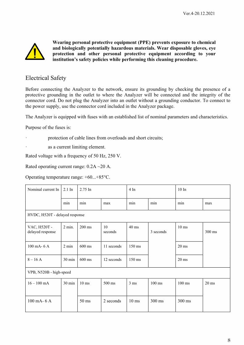
The Analyzer is equipped with fuses with an established list of nominal parameters and characteristics.
Purpose of the fuses is:
· protection of cable lines from overloads and short circuits;
· as a current limiting element.
Rated voltage with a frequency of 50 Hz, 250 V.
Rated operating current range: 0.2A ~20 A.
Operating temperature range: +60...+85°C.
Nominal current In 2.1 In 2.75 In 4 In 10 In
min min max min min min max
HVDC, H520T - delayed response
VAC, H520T - delayed response
2 min. 200 ms 10 seconds
40 ms 3 seconds
10 ms 300 ms
100 mА- 6 А 2 min 600 ms 11 seconds 150 ms 20 ms
8 – 16 А 30 min 600 ms 12 seconds 150 ms 20 ms
VPB, N520B - high-speed
16 – 100 mА 30 min 10 ms 500 ms 3 ms 100 ms 100 ms 20 ms
100 mА- 6 А 50 ms 2 seconds 10 ms 300 ms 300 ms

Ver.4-20.12.2021
9
No hindered access to the network switch of the Analyzer is allowed.
If liquid gets inside the Analyzer, disconnect it from the mains and contact an authorized service center.
Safety Rules during Operation
Do not expose the Analyzer to heat and sunlight or other strong light sources.
If you need to stop the Analyzer, use the Pause button.
Service rules
Do not open the Analyzer on your own. The internal part of the Analyzer does not contain any user-serviceable components.
The Analyzer should be serviced only by specially trained qualified personnel.
Operating Limitations
When using the Analyzer, take precautions regarding the effects of magnetic fields, external electrical influences, electrostatic discharges, pressure or pressure drops, restarting, and sources of thermal ignition.
Strong electromagnetic fields (generated by unshielded radio frequency sources) can interfere with proper operation and may lead to the device malfunction and incorrect results.
- Do not use the Analyzer near sources of strong electromagnetic fields as these fields may interfere with its proper operation.
- Assess the electromagnetic environment before operating the Analyzer. - Mitigate interference.
Virus handling and biological material recording, storage, transfer, and transportation should be performed in strict compliance with local guidelines.
Follow safety procedures set by your institution and local authorities for disposing of the biological material.
When operating, always follow these guidelines:
- Treat biological samples being tested as potentially infectious. - Ensure the staff complies with biosafety rules and guidelines and takes the required
actions to prevent nucleic acid contamination of the samples being tested as well as the rooms and equipment.
Precautions against Electromagnetic Factors
During the Analyzer operation, take precautions against the influence of magnetic fields, external electrical influences, electrostatic discharges, pressure or pressure drops, reloading, and sources of thermal ignition. Strong electromagnetic fields (originating from unshielded radio frequency sources) can interfere with proper operation and lead to the Analyzer malfunction and incorrect results.
Do not use the Analyzer near sources of strong electromagnetic fields, as these fields may interfere with proper operation.

Ver.4-20.12.2021
10
Evaluate the electromagnetic environment before operating the Analyzer and take measures to mitigate the interference.
Environmental Impact
The Analyzer does not pose a biological hazard under normal operating conditions.
Disposal of the Analyzer is carried out in accordance with applicable local regulations. The Analyzer contains no substances posing an immediate threat to the environment.
Ver.4-20.12.2021
11
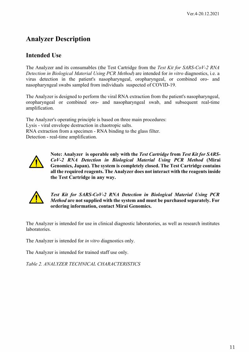
Analyzer Description Intended Use The Analyzer and its consumables (the Test Cartridge from the Test Kit for SARS-CoV-2 RNA Detection in Biological Material Using PCR Method) are intended for in vitro diagnostics, i.e. a virus detection in the patient's nasopharyngeal, oropharyngeal, or combined oro- and nasopharyngeal swabs sampled from individuals suspected of COVID-19. The Analyzer is designed to perform the viral RNA extraction from the patient's nasopharyngeal, oropharyngeal or combined oro- and nasopharyngeal swab, and subsequent real-time amplification. The Analyzer's operating principle is based on three main procedures: Lysis - viral envelope destruction in chaotropic salts. RNA extraction from a specimen - RNA binding to the glass filter. Detection - real-time amplification.
Note: Analyzer is operable only with the Test Cartridge from Test Kit for SARS-CoV-2 RNA Detection in Biological Material Using PCR Method (Mirai Genomics, Japan). The system is completely closed. The Test Cartridge contains all the required reagents. The Analyzer does not interact with the reagents inside the Test Cartridge in any way. Test Kit for SARS-CoV-2 RNA Detection in Biological Material Using PCR Method are not supplied with the system and must be purchased separately. For ordering information, contact Mirai Genomics.
The Analyzer is intended for use in clinical diagnostic laboratories, as well as research institutes laboratories. The Analyzer is intended for in vitro diagnostics only. The Analyzer is intended for trained staff use only. Table 2. ANALYZER TECHNICAL CHARACTERISTICS

Ver.4-20.12.2021
12
Parameter Value Weight 0.575 ± 0.05 kg Power consumption 20 V DC, 4.8 А Max Power adapter (user-supplied)
USB Type C connector Power Delivery 1.0/2.0/3.0
Battery LiPo 3,000mAh 8.4 V Continuous run time Not less than 8 hours Time to start the operating mode No more than 60 s Computer interface USB 2.0 OS Windows, MacOS Test type PCR amplification Heater temperature 67 ℃ Detection wavelength 525 nm Excitation wavelength 500 nm
Picture 1. Analyzer Overall Dimensions
Table 3. ANALYZER COMPONENTS OVERVIEW
Ver.4-20.12.2021
13
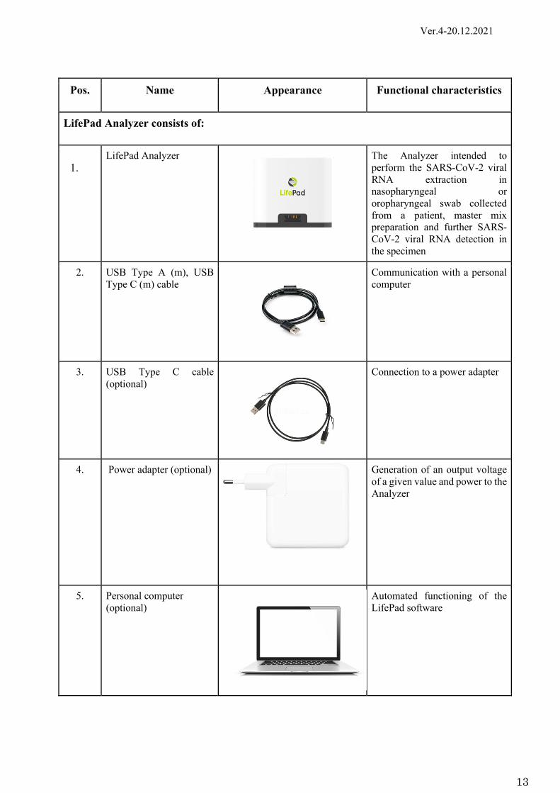
Pos. Name Appearance Functional characteristics
LifePad Analyzer consists of:
1. LifePad Analyzer The Analyzer intended to
perform the SARS-CoV-2 viral RNA extraction in nasopharyngeal or oropharyngeal swab collected from a patient, master mix preparation and further SARS-CoV-2 viral RNA detection in the specimen
2. USB Type A (m), USB Type C (m) cable
Communication with a personal computer
3. USB Type C cable (optional)
Connection to a power adapter
4. Power adapter (optional)
Generation of an output voltage of a given value and power to the Analyzer
5. Personal computer (optional)
Automated functioning of the LifePad software

Ver.4-20.12.2021
14
6. Portable data storage device with software (optional)
Storage of the LifePad software information and temporarily connection to a PC via a standard connector
7. Operational documents Defines the operation rules and (or) reflects information certifying the values of the main parameters and characteristics of the device guaranteed by the manufacturer, as well as the information on its operation during the specified service life
7.1. User manual
7.2. Datasheet
7.3 Quick start guide
8. Package Protection of the medical device from damage and loss, protection of the environment from pollution, as well as ensuring the medical device application process

Ver.4-20.12.2021
15
The Analyzer, together with the Test Cartridge and the LifePad software, performs the nucleic acid extraction from a patient's nasopharyngeal and/or oropharyngeal swab and the target RNAs detection using real-time nucleic acid amplification.
The Analyzer’s functions: ● Detection of the Test Cartridge insertion to the Analyzer. ● Validity (expiry date, type) detection of the Test Cartridge. ● Extraction, amplification, and detection of the target RNA. ● Result interpretation (in the LifePad software). ● Test results storage (in the LifePad software). ● Test results saving in .pdf format, test results printing. ● Last test results storage (in the Analyzer).
The Analyzer performance is controlled by an external computer under Windows/Mac OS. The Analyzer connects the computer via an USB Type-C cable. To operate the Analyzer, the LifePad software must be preinstalled. The software is available for downloading on the Mirai Genomics official website at https://miraigenomics.com/. One computer can work with several Analyzers at the same time.
To indicate the Analyzer current status, there is a display located on the Analyzer front panel. The Analyzer is powered by a built-in battery. The batteries are charged via a USB Power Delivery compatible AC adapter.
Picture 2. Main Controls Location
The Analyzer is a combination of pneumatic, mechanical, heating, and detection modules. The modules affect the reagents in the Test Cartridge, enabling motion from one well to another, mixing, filtering to ensure the viral RNAs extraction and detection in a clinical specimen. Table 5. ANALYZER MODULES
Ver.4-20.12.2021
16
Module Intended purpose
1. Pneumatic and switching modules
Fluids controlled motion in the Test Cartridge
2. Heating and detection modules
The reaction mixture heating and the fluorescence level detection
3. Interface module PC control Data transfer Clustering Read / Write Test Cartridge Data Displaying the device current status
4. Power module Device power and battery charge control
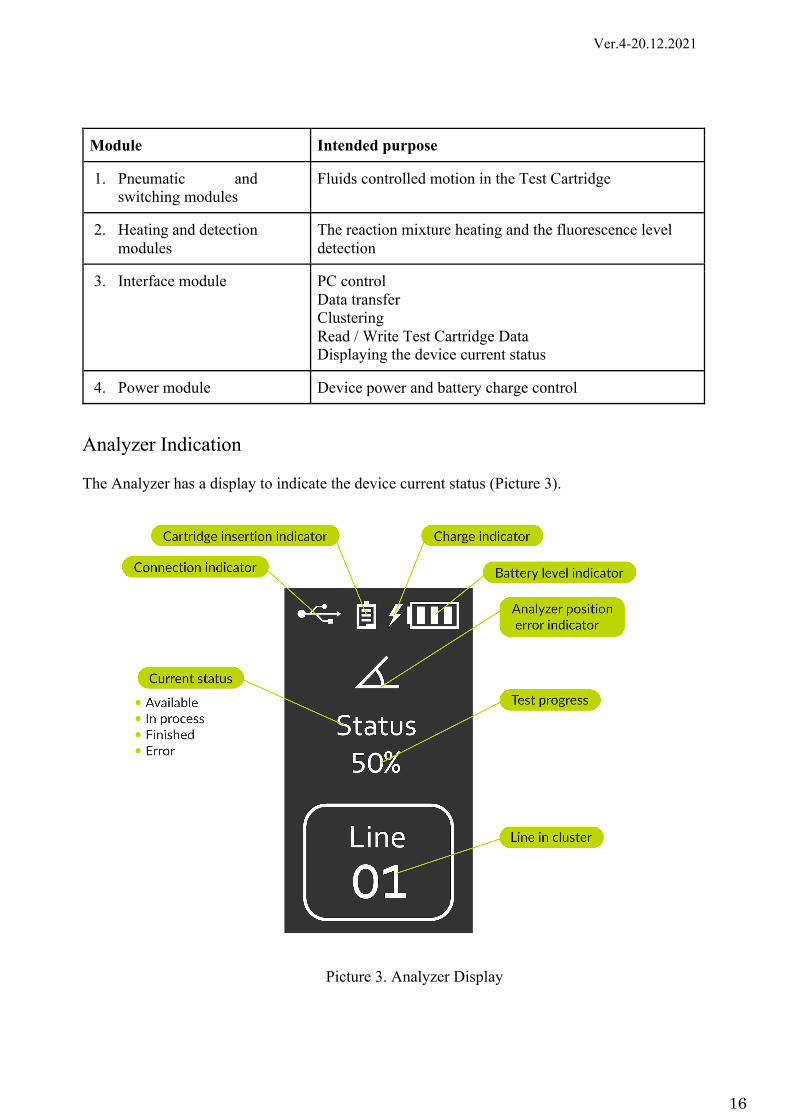
Analyzer Indication The Analyzer has a display to indicate the device current status (Picture 3).
Picture 3. Analyzer Display

Ver.4-20.12.2021
17
Operating, Storage and Transportation Conditions
The Analyzer is transported by all types of enclosed shipping in accordance with rules of cargo transportation applicable to this type of transport. Vehicles must be covered, dry and clean.
During loading, unloading, as well as transportation and storage, measures must be taken to protect the Analyzer from damage and contamination.
The Analyzer is transported in the Manufacturer’s packaging.
Table 4. ANALYZER OPERATING, STORAGE AND TRANSPORTATION CONDITIONS
Parameter Value Operating conditions Temperature: +15 ... +35 ℃.
Relative humidity: 30 - 85 % (non-condensing) Storage conditions Temperature: -20 ... +40 ℃
Relative humidity: 30 - 85 % (non-condensing) In a well-ventilated room
Transportation conditions Temperature: -40 ... +65 ℃ Relative humidity: 10 - 90 % (non-condensing)
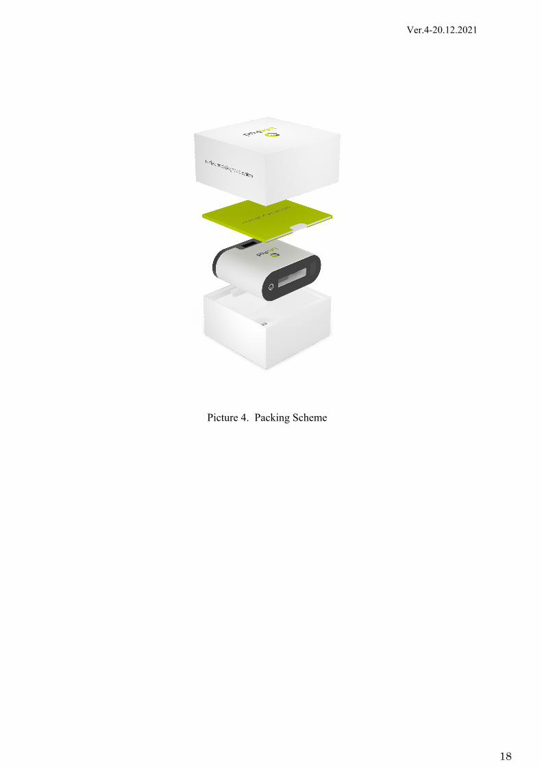
Packing To ensure the safe delivery, the Analyzer is packaged in a cardboard box with protective inserts.
Ver.4-20.12.2021
18
Picture 4. Packing Scheme
Ver.4-20.12.2021
19
Analyzer Operation Biological Material Use Limitations
To extract the RNA and detect the virus presence, only the Test Cartridge from the Test Kit for SARS-CoV-2 RNA Detection in Biological Material Using PCR Method can be used. After sampling, the specimen is placed into the SSB tube to inactivate the sample at the sampling point according to the instruction for use. After that, the sample is transported to the extraction site. To achieve the stated analytical sensitivity, the sample aliquot should be at least 100 μl.
Carrying / Installation The Analyzer is intended for indoor use only. Place the Analyzer in the upright position on a stable work surface. Keep the Analyzer away from the direct sunlight. Do not install the Analyzer nearby other devices that could generate vibration (for example, a centrifuge). Install the Analyzer near an AC outlet. Single and Cluster Modes
There are 2 connection options for the Analyzer: single and cluster ones. In case of a cluster connection scheme, up to 8 devices can be connected in one cluster in series.
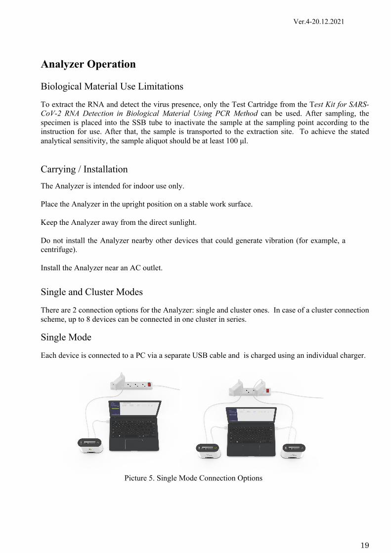
Single Mode
Each device is connected to a PC via a separate USB cable and is charged using an individual charger.
Picture 5. Single Mode Connection Options

Ver.4-20.12.2021
20
Cluster Mode
Cluster connection scheme allows for optimizing the number of connections and cables in the workplace by daisy-chaining devices to each other. The power and interface of the devices in the cluster are provided through the first Analyzer (this does not change the functionality of the other Analyzers in the cluster). Several clusters can be connected to one PC via a USB hub.
Limitations: Up to 8 Analyzers can be connected to one cluster. Up to 12 clusters can be connected to one PC.
Picture 6. Cluster Consisting of 8 Analyzers
Picture 7. 12 Clusters Connection

Ver.4-20.12.2021
21
To connect the Analyzers into a cluster, pull out the panel with the connector on the Analyzer bottom until it clicks and connect the Analyzer to the next device. Select the Cluster operating mode in the software. Please refer to the Software Description section for details.
Picture 8. Analyzers Clustering
Ver.4-20.12.2021
22
Software Installation
To provide functionality, embedded software (software) version 2.0.0 or higher is used, which is an integral part of the Analyzer.
To control the Analyzer and display data on the process of the procedure for analyzing biological samples, the LifePad software, and software version 2.0.0 is used.
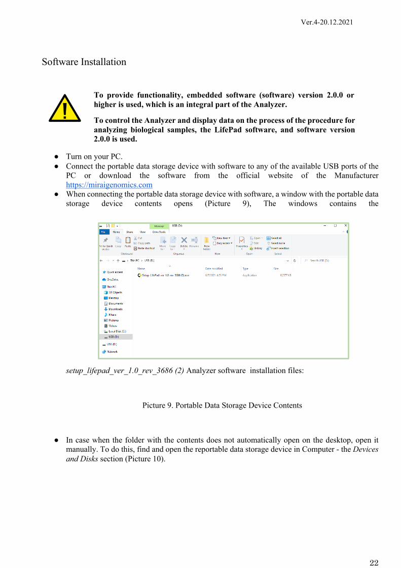
● Turn on your PC. ● Connect the portable data storage device with software to any of the available USB ports of the
PC or download the software from the official website of the Manufacturer https://miraigenomics.com
● When connecting the portable data storage device with software, a window with the portable data storage device contents opens (Picture 9), The windows contains the
setup_lifepad_ver_1.0_rev_3686 (2) Analyzer software installation files:
Picture 9. Portable Data Storage Device Contents
● In case when the folder with the contents does not automatically open on the desktop, open it manually. To do this, find and open the reportable data storage device in Computer - the Devices and Disks section (Picture 10).

Ver.4-20.12.2021
23
Picture 10. Computer – Devices and Disks
● Run the setup_lifepad_ver_1.0_rev_3686 (2) installation file (Picture 11).
Picture 11. LifePad Software Installation Start
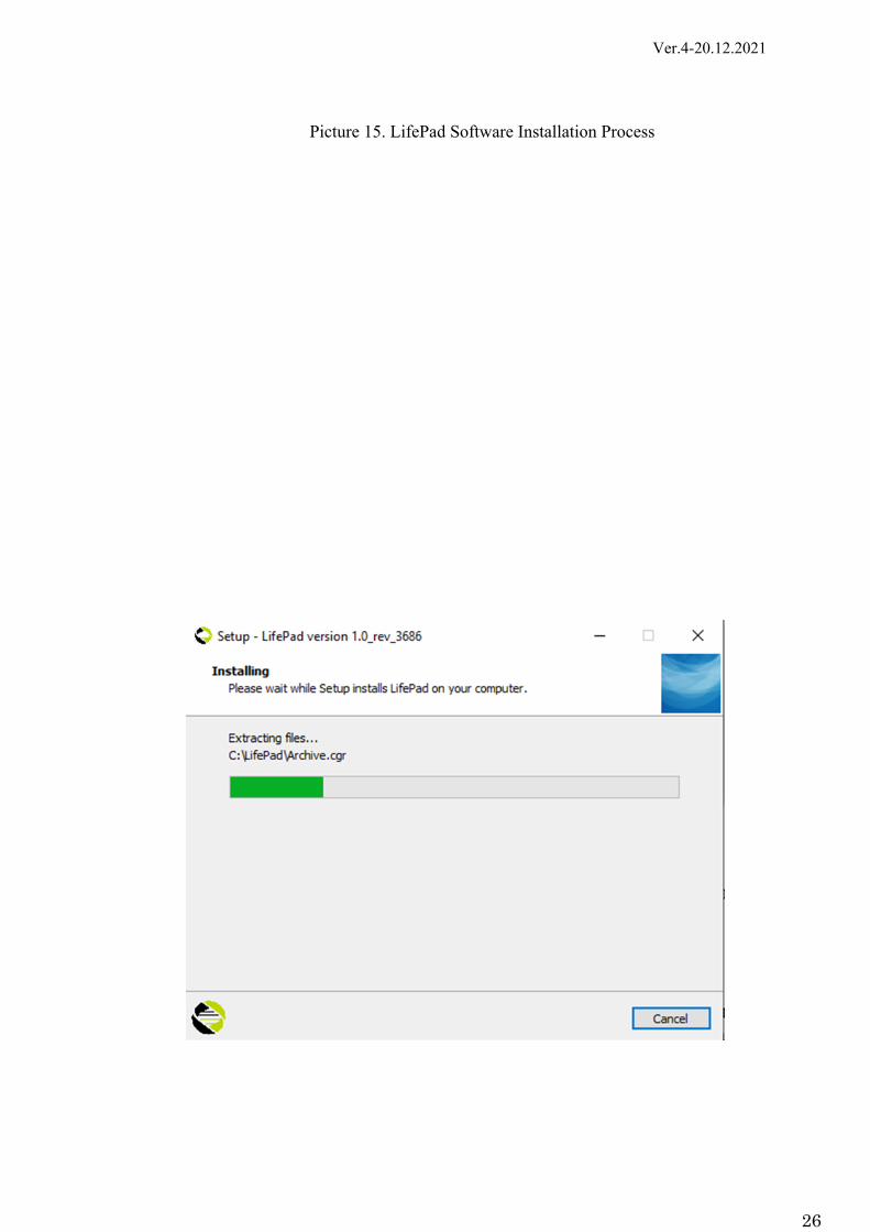
● Follow the prompts during installation. It is recommended not to change the default settings (Picture 12- Picture 15):

Ver.4-20.12.2021
24
Picture 12. Press Next

Ver.4-20.12.2021
25
Picture 13. Press Next
Picture 14. Press Install
Ver.4-20.12.2021
26
Picture 15. LifePad Software Installation Process
Ver.4-20.12.2021
27
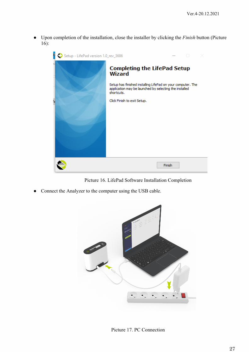
● Upon completion of the installation, close the installer by clicking the Finish button (Picture 16):
Picture 16. LifePad Software Installation Completion
● Connect the Analyzer to the computer using the USB cable.
Picture 17. PC Connection

Ver.4-20.12.2021
28
● Check the battery charge level; if the charge level is low, connect the power adapter.
Picture 18. Charging Analyzer from the Mains
● Prepare the Test Cartridge, the swab and the tube with the SSB solution from Test Kit for
SARS-CoV-2 RNA Detection in Biological Material Using PCR Method.
Picture 19. Test Cartridge and Consumables
Ver.4-20.12.2021
29
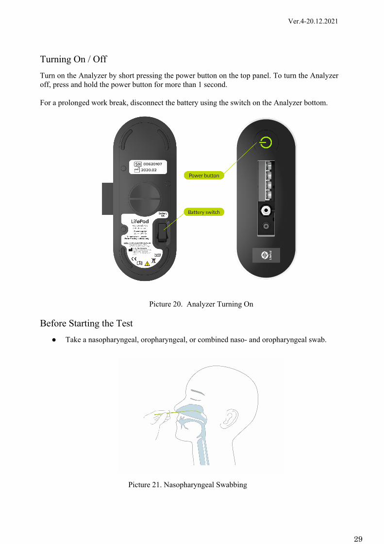
Turning On / Off Turn on the Analyzer by short pressing the power button on the top panel. To turn the Analyzer off, press and hold the power button for more than 1 second. For a prolonged work break, disconnect the battery using the switch on the Analyzer bottom.
Picture 20. Analyzer Turning On Before Starting the Test
● Take a nasopharyngeal, oropharyngeal, or combined naso- and oropharyngeal swab.
Picture 21. Nasopharyngeal Swabbing

Ver.4-20.12.2021
30
Picture 22. Oropharyngeal Swabbing
● Insert the sample into the tube with the SSB solution and rotate carefully.
Picture 23. Swab Insertion into SSB
● Remove the swab from the tube with the SSB solution and discard it in a biohazardous
waste container. If immediate testing is not possible, recap the SSB tube. The prepared sample may be stored at room temperature for up to 24 hours and up to 7 days at +2…+4°С.

Ver.4-20.12.2021
31
● Place the cap with a dropper nozzle onto the tube.
Picture 24. Tube Closing
● Transfer the liquid to the Test Cartridge inlet up to the mark and close the Test Cartridge
tightly. The rest of the SSB can be kept for re-analysis.
Picture 25. Placing the Sample into Test Cartridge
● Remove the protective sticker from the Test Cartridge.

Ver.4-20.12.2021
32
Picture 26. Protective Sticker Removal
● Insert the Test Cartridge into the Analyzer up to the red insertion line. Ensure the Test
Cartridge is positioned correctly (see Picture 28, Picture 29).
Picture 27. Test Cartridge Insertion into Analyzer

Ver.4-20.12.2021
33
Picture 28. Test Cartridge Correct Positioning
Picture 29. Test Cartridge Incorrect Positioning

Ver.4-20.12.2021
34
● To check the Analyzer is installed correctly and ready for work: - Make sure that the Test Cartridge is properly installed. - Make sure that the Analyzer display shows AVAILABLE ready-to-work status. - Make sure that the Analyzer displays no ERROR status. - Make sure that the battery charge level is sufficient to perform testing. - Check Analyzer external connections: network power cable, USB cable to a PC (as shown in
Pictures 17-18). - Turn on the Analyzer by setting the switch on the Analyzer back to the I position.
- Make sure there is no warning signs ( ) on the display showing the Analyzer incorrect position.
- Turn on the PC and run the LifePad software. ● Enter the patient ID in the software. ● Start the test (please refer to the Test Start section for details). ● Once the test is over, take out the Test Cartridge and dispose of it according to the
applicable local waste disposal guidelines.
Picture 30. Test Cartridge Taking Out
Opening of the used Test Cartridge is strictly prohibited!
Ver.4-20.12.2021
35
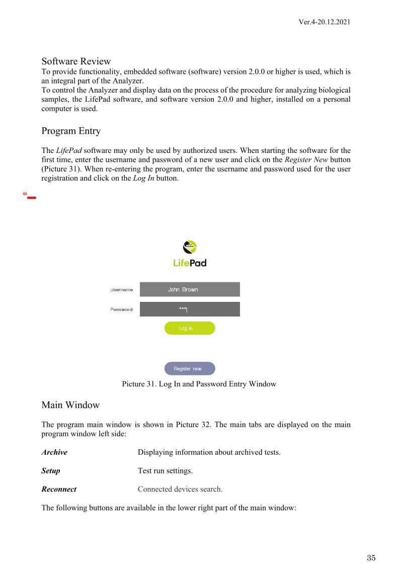
Software Review To provide functionality, embedded software (software) version 2.0.0 or higher is used, which is an integral part of the Analyzer. To control the Analyzer and display data on the process of the procedure for analyzing biological samples, the LifePad software, and software version 2.0.0 and higher, installed on a personal computer is used. Program Entry The LifePad software may only be used by authorized users. When starting the software for the first time, enter the username and password of a new user and click on the Register New button (Picture 31). When re-entering the program, enter the username and password used for the user registration and click on the Log In button.
Picture 31. Log In and Password Entry Window
Main Window The program main window is shown in Picture 32. The main tabs are displayed on the main program window left side: Archive Displaying information about archived tests. Setup Test run settings. Reconnect Connected devices search. The following buttons are available in the lower right part of the main window:

Ver.4-20.12.2021
36
Start All Start tests on all devices with the READY status.
Stop All Abort tests on all devices with the IN PROGRESS status.
Picture 32. Main Window
Test Start To prepare for the test run, connect the Analyzer to the computer via USB and turn it on. The connected device will be displayed in one of the device cells in the main window (Picture 31). When clicking on the selected Analyzer cell in the lower part of the main window, the following information is displayed:
Selected LifePad status Selected Analyzer status.
LifePad ID Analyzer serial number.
Error Absence/present of the Analyzer run-time errors.
Temperature The current temperature of the Analyzer heater current temperature.

Ver.4-20.12.2021
37
Picture 33. Connected Device in One of the Cells and the Analyzer Information Display
The connected Analyzer can have one of the statuses described in Table 6. The Analyzer status is shown on the display and in the device cell in the main window (Picture 33).

Ver.4-20.12.2021
38
Table 6. ANALYZER STATUSES Device status Description
INITIALIZATION The Analyzer initialization after its detection
AVAILABLE The Analyzer is ready for use. The Test Cartridge is not inserted into the device.
READY The Analyzer is connected to the software. The Test Cartridge is inserted into the Analyzer. The Test Cartridge was checked for:
- Its expiry date. - The Test Cartridge and the Analyzer versions match. - The test start mark absence.
The Analyzer is ready to run the test
IN PROGRESS Test is running
FINISHED The test is over. The Test Cartridge is in the Analyzer
ERROR An error was detected during the Analyzer initialization/when checking the Test Cartridge/ during the Analyzer operation
MAINTENANCE The Analyzer service maintenance
FIRMWARE UPDATE The Analyzer firmware updating When the Analyzer is turned on, its initialization takes a few seconds. The status of the Analyzer during this process is INITIALIZATION. Upon initialization completion, the Analyzer shows the AVAILABLE status. When the AVAILABLE status appears on the Analyzer display and in the device cell in the main window, insert the Test Cartridge with the specimen into the Analyzer. The Analyzer checks the Test Cartridge for its expiry date, the Test Cartridge and the Analyzer versions matching, and the test start mark absence. If the Test Cartridge meets the criteria, the Analyzer status changes to READY. Click on the Scan Sample button in the right part of the main window, enter the patient ID and press Enter. The user can also scan the patient ID given in the barcode form on the sample tube using a barcode reader. After entering the patient ID, the button name will change to Rescan sample.

Ver.4-20.12.2021
39
To start the test, click on the Start button, displayed on the right side of the selected line with the device (Picture 34). After pressing the Start button, the Analyzer status will change to IN PROGRESS.
Picture 34. Analyzer is Ready to Test
Running Tests Information After starting the test, in the lower part of the main program window, in addition to the information described above, the following data about the device is displayed: Progress The test completion percentage.
Time from start Time elapsed from the test start (excluding pretreatment).
As fluorescence data is received from the Analyzer, a fluorescence signal graph is displayed at the bottom of the main window (Picture 35). The abscissa of both graphs displays time (minutes), and the ordinate shows the fluorescence signal amplitude (relative fluorescence unit). The test result for each of the diseases contained in the Test Cartridge is considered positive if the signal graph of this disease crosses the threshold value of 200 relative fluorescence units.

Ver.4-20.12.2021
40
Picture 35. Fluorescence Signal Graphing
The Abort button is located in the lower right part of the main window. The button allows interrupting the test on the Analyzer without waiting for its completion. In the lower right part of the main window, the Save Results button is located. Clicking on this button saves a screenshot of the main window and the fluorescence signal values in a folder selected as the directory for saving test results in the Setup tab. Completed Tests Information Upon test completion, the Analyzer switches to the FINISHED status. The completed test data automatically transfers to the Archive tab. The line with the test in the Archive tab contains the following data:
User The name of the user ran the test.
Date Date and time of the test completion.
LifePad Serial Number Serial number of the device used for the test.
Sample barcode Test Cartridge serial number.
SARS-Cov2 Cq Test results for this disease.
Flu A Cq Test results for this disease.
Flu B Cq Test results for this disease.

Ver.4-20.12.2021
41
IPC Cq Internal control results.
Picture 36. Completed Test in the Archive Tab
In the Archive tab, each test channel can have one of the following results: 1) Test result - negative (N/A).
2) Test result - positive (the time when the positive result was detected is displayed).
2) Test result - invalid.
Setup Tab The following settings are available in the Setup tab (Picture 37):
Save directory The folder for saving test results when pressing the Save Results
button.
Auto position Automatic/manual assignment of a cell to the connected Analyzers.

Ver.4-20.12.2021
42
Picture 37. Setup Tab
When unchecking Auto position, the user must assign the cell for each connected device manually in the Set Position tab; otherwise, the connected devices will not be displayed in the main window.
To assign a cell in the Set Position tab, select the device, which cell is being assigned, in the list of devices (on the right) (Picture 38). Then select the device cell assignment in the lists on the left.
To save changes in the Setup tab, click on the Save & Exit button.

Ver.4-20.12.2021
43
Picture 38. Cells Assignment for Connected Devices in the Set Position Tab
Cluster Mode Operation When clustering several devices (Pictures 6, 7), the software displays the connected Analyzers. The operation of each Analyzer is controlled in the same way as when working with one device.
Picture 39. Displaying Clustered Devices in the Main Window

Ver.4-20.12.2021
44
Results Interpretation The Analyzer's operability is to be checked using an internal control sample (IPC).
Table 7. RESULTS INTERPRETATION Result SARS-CoV-2
RNA is detected SARS-CoV-2
RNA is not detected
SARS-CoV-2 RNA is detected
Invalid*
Internal Control (IPC)
Positive Positive Negative Negative
Specimen Positive Negative Positive Negative
*Retest the specimen. The result could not be interpreted.
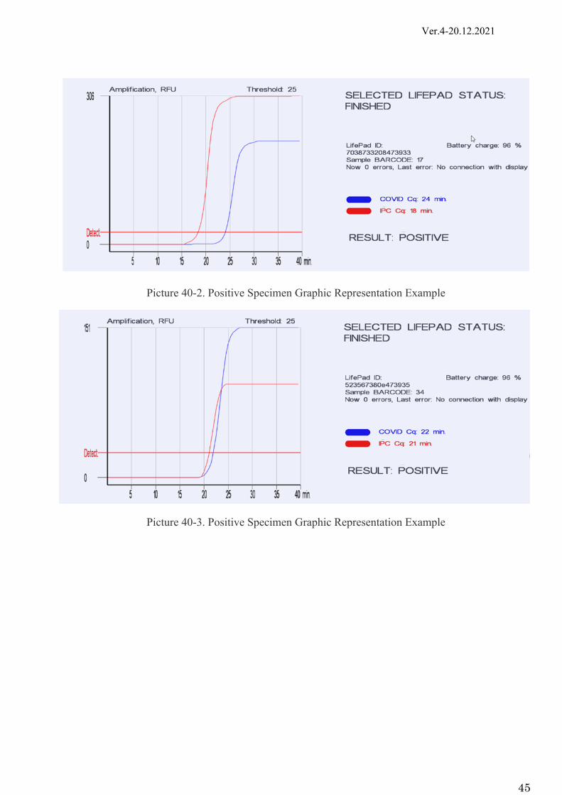
The SARS-CoV-2 positive specimen graphic representation examples are given in Pictures 40.1-40.7. The blue sigmoid line is a specimen with the detected SARS-CoV-2 coronavirus. The red sigmoid line is internal positive control (IPC).
Picture 40-1. Positive Specimen Graphic Representation Example
Ver.4-20.12.2021
45
Picture 40-2. Positive Specimen Graphic Representation Example
Picture 40-3. Positive Specimen Graphic Representation Example

Ver.4-20.12.2021
46
Picture 40-4. Positive Specimen Graphic Representation Example
Picture 40-5. Positive Specimen Graphic Representation Example

Ver.4-20.12.2021
47
Picture 40-6. Positive Specimen Graphic Representation Example
Picture 40-7. Positive Specimen Graphic Representation Example
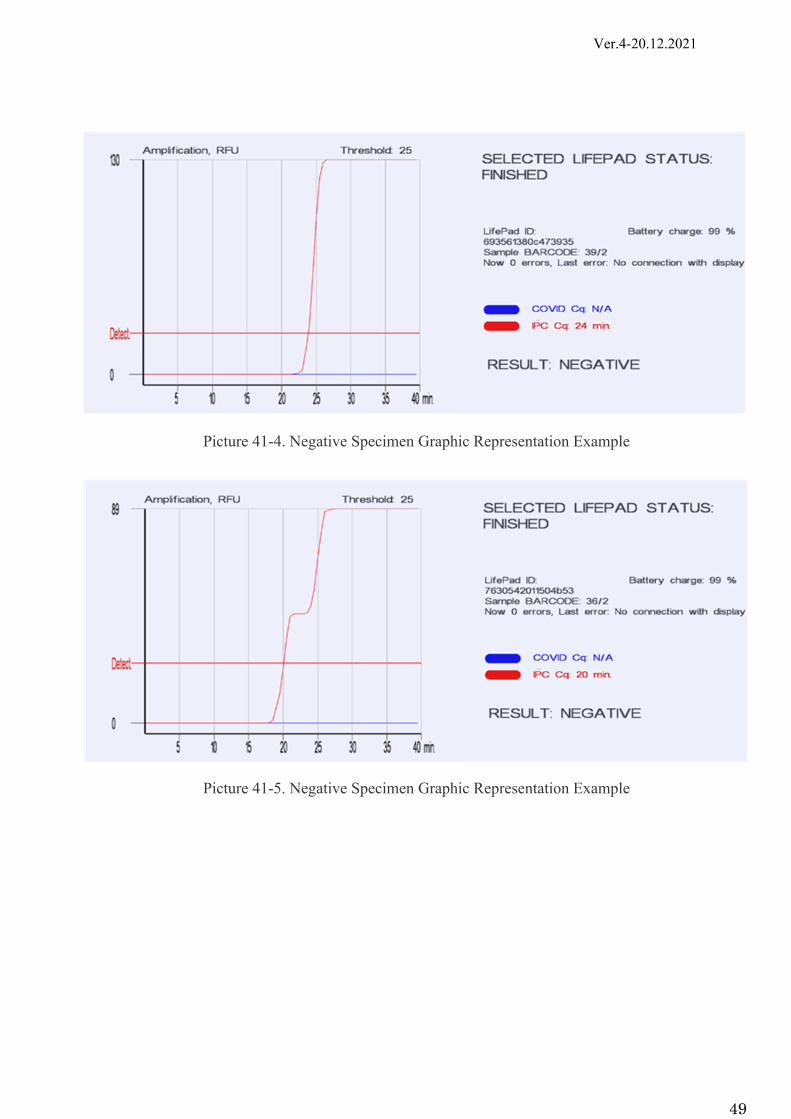
The SARS-CoV-2 negative specimen graphic representation examples are given in Picture 41.1-41.6.
The blue sigmoid line is a specimen where the SARS-CoV-2 coronavirus was not detected.
The red sigmoid line is internal positive control (IPC).
Picture 41-1. Negative Specimen Graphic Representation Example

Ver.4-20.12.2021
48
Picture 41-2. Negative Specimen Graphic Representation Example
Picture 41-3. Negative Specimen Graphic Representation Example
Ver.4-20.12.2021
49
Picture 41-4. Negative Specimen Graphic Representation Example
Picture 41-5. Negative Specimen Graphic Representation Example

Ver.4-20.12.2021
50
Picture 41-6. Negative Specimen Graphic Representation Example
The results are interpreted based on the fluorescent curve rise presence (or absence) and the threshold cycle (Ct) value in minutes.
The result is considered positive if the fluorescence accumulation curve for the corresponding specimen has a specific sigmoid shape and crosses the threshold line (a red solid line on the graph, fixed at 200 and not changing its value).
The value of the reaction time at the time of exit should not exceed 35 minutes. The amplitude of the signal does not matter.
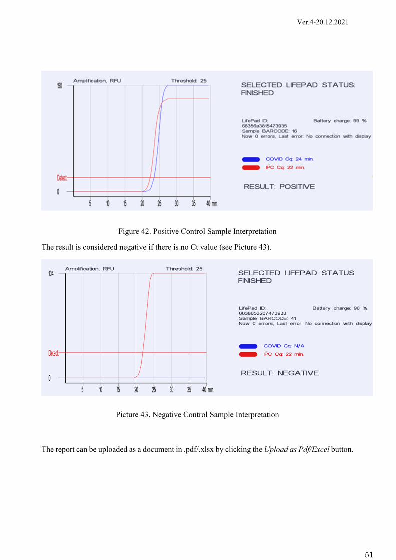
Each Test Kit for SARS-CoV-2 RNA Detection in Biological Material Using PCR Method contains positive and negative control samples required to check the quality of the kit.
Ver.4-20.12.2021
51
Figure 42. Positive Control Sample Interpretation
The result is considered negative if there is no Ct value (see Picture 43).
Picture 43. Negative Control Sample Interpretation
The report can be uploaded as a document in .pdf/.xlsx by clicking the Upload as Pdf/Excel button.

Ver.4-20.12.2021
52
Troubleshooting The Analyzer performs self-checking after each switch-on as well as during operation. In the event of a malfunction, the Error message appears on the device screen, and an error code appears in the status line corresponding to this Analyzer in the software (Picture 36). The list of errors, their codes, and actions to eliminate the errors is shown in Table 8. Table 8. MALFUNCTIONS AND TROUBLESHOOTING
Error Code
Reason/Source Where How to Fix
01 01 No connection Servo Please contact the service centre
01 02 Heater
01 03 Optics
01 04 RFID antenna
01 05 Battery (temperature sensor)
01 06 Pressure sensor
01 07 Charge circuit
01 08 Power adaptor
01 09 Accelerometer
01 0A Display
02 01 Insufficient supply voltage/current
Servo
02 02 Battery
02 03 Common line
03 01 Overheating Servo
03 02 Heater
03 03 Heater

Ver.4-20.12.2021
53
04 01 Incorrect homing position
Servo Please contact the service centre
04 02 Incorrect homing position
Device position according to the accelerometer
Place the device on a horizontal surface
04 03 Inserted Test Cartridge was detected when the device was turned on
RFID module If ERROR status is displayed, take out the Test Cartridge and/or restart the Analyzer
05 01 Inability to achieve the correct position (value) during the test
Servo Please contact the service centre
05 02 Device incorrect position
Device position according to the accelerometer
05 03 The Test Cartridge was taken out during the test
RFID module
06 01 The pressure doesn't change
Pressure sensor Please contact the service centre
06 02 The pressure level is insufficient
07 01 Heater low temperature on one or all channels
Heater Please contact the service centre
08 01 Incorrect values of the optical module sensors
Optics
09 01 Errors when recognizing the Test Cartridge
Take out the Test Cartridge and re-insert it
09 02 Errors when writing information to the Test Cartridge
Use another Test Cartridge
0A 01 System update error Main board Please contact the service centre
0B 01 Battery Voltage level is exceeded Please contact the service centre
0B 02 Battery Voltage level is reduced Plug in the power adapter
0B 03 Battery error Please contact the service centre

Ver.4-20.12.2021
54
In case of any other malfunctions, not described in the User Manual, please immediately contact the Manufacturer.

Ver.4-20.12.2021
55
Analyzer Maintenance General
The purpose of the Analyzer maintenance is to maintain the Analyzer in its good working condition and ensure its maximum service life.
Maintenance is performed by qualified staff who have read the User Manual carefully.
The Analyzer design requires minimal maintenance in a normal laboratory operation environment.
Prevent any mechanical damage to the Device and do not expose the surface of the Device to any liquids.
Maintenance Procedure
The maintenance staff must do the following (with the indicated frequency):
1) Perform external inspection of the Device for any damage to its surface. 2) Verify the condition (integrity) of the power adapter and the reliability of its connection
to the Analyzer. External inspection frequency: every time before switching on the Device.
3) Remove dust and dirt from the surface of the Device in a timely manner using a dry wipe. 4) If potentially contaminated samples or used reagents are on the surface of the Analyzer,
disinfect the surfaces by wiping out in compliance with effective in-house rules. Routine Maintenance
The routine maintenance of the Device is carried out by an authorized service provider. It is strictly forbidden to carry out any repairs by your own resources.
Ver.4-20.12.2021
56
Analyzer Disposal The Analyzer that has become unusable, including due to the expiration of its shelf life, must be disposed of.
EU Waste Electrical and Electronic Equipment (WEEE) Directive
In August of 2005, the European Union (EU) implemented the EU WEEE Directive 2002/96/EC and later the WEEE Recast Directive 2012/19/EU requiring Producers of electronic and electrical equipment (EEE) to manage and finance the collection, reuse, recycling and to appropriately treat WEEE that the Producer places on the EU market after August 13, 2005.
The goal of this directive is to minimize the volume of electrical and electronic waste disposal and to encourage reuse and recycling at the end of life.
K.K. Mirai Genomics has met its national obligations to the EU WEEE Directive by registering in those countries to which K.K. Mirai Genomics is an importer. K.K. Mirai Genomics has also elected to join WEEE Compliance Schemes in some countries to help manage customer returns at end-of-life.
If you have purchased K.K. Mirai Genomics-branded electrical or electronic products in the EU and are intending to discard these products at the end of their useful life, please do not dispose of them with your other household or municipal waste.
K.K. Mirai Genomics has labeled its branded electronic products with the WEEE Symbol to alert our customers that products bearing this label should not be disposed of in a landfill or with municipal or household waste in the EU.
For professional users in the European Union
If you wish to discard electrical and electronic equipment (EEE), please contact your dealer, supplier or our EU Representative for further information.
For disposal in countries outside of the European Union
This symbol is only valid in the European Union (EU). If you wish to discard this product, please contact your local authorities or dealer and ask for the correct method of disposal.