Life Extension Technique for Asset Integrity of Welded ... · 5Politeknik Sultan Salahuddin Abdul...
30
1 Life Extension Technique for Asset Integrity of Welded Structure using HFMI/PIT: A Review on Researches and Applications Yupiter HP Manurung *1 , Mohamed Ackiel Mohamed 1,2,3 , Dahia Andud 1,2,3 , Azrriq Zainul Abidin 1,3 , Salina Saidin 1,4 , Khairulnizam Kasim 1,5 , Dendi Prajadiana Ishak 1,3,6,7 , Luthffi Idzhar Ismail 8 , Jeffri Isheak 9 and Nik Ahmad Shahmmin 10 1 Faculty of Mechanical Engineering, UiTM Shah Alam, Malaysia 2 University Kuala Lumpur Malaysia French Institute, Bangi, Malaysia 3 Technogerma Engineering & Consulting, Shah Alam, Malaysia 4 Nusantara Technologies Sdn. Bhd., Shah Alam, Malaysia 5 Politeknik Sultan Salahuddin Abdul Aziz Shah, Shah Alam, Malaysia 6 University of Indonesia, Jakarta, Indonesia 7 Bogor Safety Institute, Bogor, Indonesia 8 Calidad Sdn. Bhd., Banting, Malaysia 9 Castral Technologies Sdn. Bhd., Sarawak, Malaysia 10 MSc.Software Corporation, Malaysia *Corresponding author’s phone: +60-12-607 70 56 E-mail: [email protected]
Transcript of Life Extension Technique for Asset Integrity of Welded ... · 5Politeknik Sultan Salahuddin Abdul...
1
Life Extension Technique for Asset Integrity of Welded
Structure using HFMI/PIT:
A Review on Researches and Applications
Yupiter HP Manurung*1, Mohamed Ackiel Mohamed1,2,3, Dahia Andud1,2,3,
Azrriq Zainul Abidin1,3, Salina Saidin1,4, Khairulnizam Kasim1,5, Dendi Prajadiana
Ishak1,3,6,7, Luthffi Idzhar Ismail8, Jeffri Isheak9 and Nik Ahmad Shahmmin10
1Faculty of Mechanical Engineering, UiTM Shah Alam, Malaysia
2University Kuala Lumpur Malaysia French Institute, Bangi, Malaysia
3Technogerma Engineering & Consulting, Shah Alam, Malaysia
4Nusantara Technologies Sdn. Bhd., Shah Alam, Malaysia
5Politeknik Sultan Salahuddin Abdul Aziz Shah, Shah Alam, Malaysia
6University of Indonesia, Jakarta, Indonesia
7Bogor Safety Institute, Bogor, Indonesia
8Calidad Sdn. Bhd., Banting, Malaysia
9Castral Technologies Sdn. Bhd., Sarawak, Malaysia
10MSc.Software Corporation, Malaysia
*Corresponding author’s phone: +60-12-607 70 56
E-mail: [email protected]
2
ABSTRACT
In this paper, High Frequency Mechanical Impact (HFMI) using Pneumatic Impact
Treatment (PIT) which can be applied for new or aging welded structure towards asset
integrity will be discussed. The technology HFMI/PIT which falls under post weld
treatment process is primarily aimed to enhance fatigue life and to strengthen welded joint.
At first, the basic principle on fatigue of welded structure based on the IIW
Recommendation will be briefly described. Further, various investigations conducted by
prominent research universities or institutions and various industrial applications in
European countries will be reviewed and discussed. Lastly, the development of new
research cluster specialized on WELD FATIGUE INTEGRITY as one of the pioneers in
Malaysia and also the current as well as the future research on HFMI/PIT carried out under
Advanced Manufacturing Technology Excellence Centre (AMTEx) at Faculty of
Mechanical Engineering UiTM Shah Alam will be presented. As conclusion, it is stated
that HFMI/PIT can be applied for extending the structural life and also for design
optimization.
Keywords: HFMI, PIT, Weld Fatigue Integrity, IIW
3
1.0 INTRODUCTION
Failures due to fatigue in welded structures continues to be topic deserving wide
focus due to its contributions to loss of life and substantial costs each year all over the
world. Fatigue is still the principle cause for breakdown of welded structures in steel
bridges, ship structures and offshore structures. Fluctuating loads during in-service
conditions are constantly subjected to these types of structural details and components. The
ever substantial improvement of the socio-economy has led to the need of structures with
longer life cycles, better performance and lower weight. This will shore up extensive use of
accurate and more efficient fatigue design methods and the design methods must be
connected to quality requirements which can be understood and managed during
production [1, 2].
Fatigue cracks normally instigate and grow in the vicinity of welds when subjected
to variable amplitude loading even if the dynamic stresses are reticent and well below the
yield limit. It is common that the choice of material is very often optimized by choosing
high strength material to allow for higher stresses and reduced dimension taking advantage
of the yield criterion. However, the strength of the base material of the joining members is
not the dominant factor for the fatigue strength of a welded joint. It is primarily governed
by the local and global geometry of the joint. Hence, an increase in the yield stress may not
improve the fatigue strength significantly. This makes the fatigue criterion a major issue. It
is the fatigue strength that determines the final dimension of structural members such as
stiffeners and the designated weld profile dimensions. The local weld geometry of the joint
namely the weld profile dimension is highly dependent on the continuous development of

4
welding techniques and production quality control. Welding without any improvement
gives rise to local stress concentration, residual stresses and different types of defects,
these features combined with high applied cyclic and complex service loading will give
rise to failure due to fatigue [3].
A recent report under the Key Programme 4 (KP4) “Ageing and Life Extension
Programme” written by the Health and Safety Executive (HSE), UK underlined that
‘Ageing equipment is equipment for which there is evidence or likelihood of significant
deterioration and damage taking place since new, or for which there is insufficient
information and knowledge available to know the extent to which this possibility exists.
The significance of deterioration and damage relates to the potential effect on the
equipment’s functionality, availability, reliability and safety. Just because an item of
equipment is old does not necessarily mean that it is significantly deteriorating and
damaged. All types of equipment can be susceptible to ageing mechanisms.’ Inspections
during this program also found not all structural analyses were up to date. Some fatigue
and redundancy analyses were incomplete or missing and there was a need to clearly
identify all the safety critical risks. Some installations designed to older rules had no
fatigue assessments carried out. It is also stated in the report that analyses indicated ca 40%
of the underwater jacket brace members had a reserve strength ratio less than 1.85
(reference ISO 19902), and ca 40% of the underwater brace members had welds with
fatigue lives less than the operational life. While not a KP4 finding, the report stated that
there have been recent reports of incidents of cracked teeth on jack-up mobile offshore
drilling unit (MODU) legs [4].
5
Remedies to this situation include the introduction of various standards and fatigue
design codes. The foundation of such codes rely, in some cases, on old concepts that do not
easily translate to the output from modern computer programmes and are also limited to
rather simplified structures. This instigated the International Institute of Welding (IIW) to
develop the recommendations on fatigue of welded components and structures and on the
effect of weld imperfections in respect to fatigue being first published in 1996 and updates
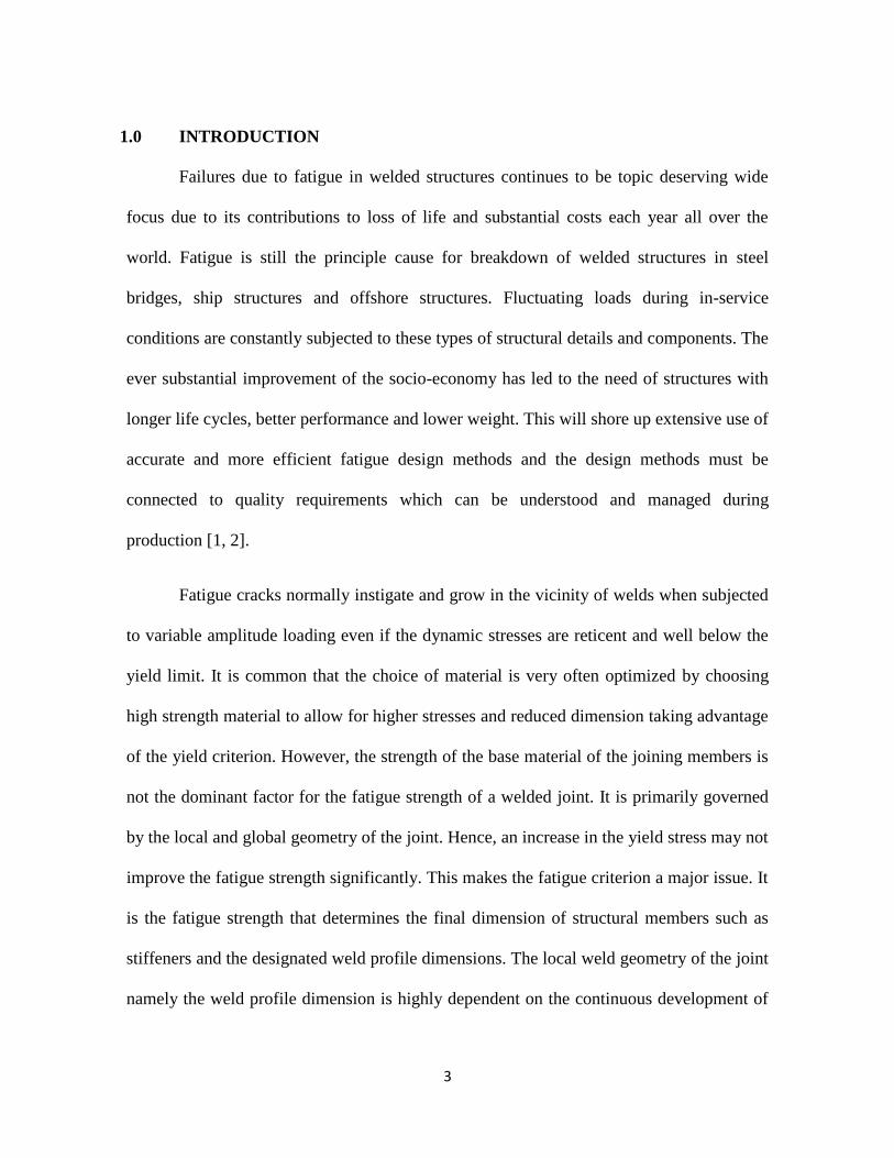
finalized in 2006. This recommendation by the Commission XIII of IIW covers all current
methods namely the nominal stress, structural stress, notch stress method as well as
fracture mechanics assessment procedures. Figure 1 shows the FAT value and stress cases.
Figure 1: Selection of FAT cases in the nominal stress assessment method (left) and
Selection of stress cases definitions (right)
The determination of the fatigue life cycle of particular welded structures has led to
the invention and development of various fatigue enhancement methods. The most notable
methods are shot peening, burr grinding, ultrasonic impact technology (UIT), TIG dressing
and Pneumatic impact treatment (PIT). However, the past decade has seen a remarkable
development in the high frequency mechanical impact method (HFMI) as a reliable,

6
effective and user-friendly method for post-weld fatigue enhancement technique for
welded structures. Fatigue strength improvement factors in all of fatigue design methods
for HFMI improved welds are defined as the characteristic fatigue strength at N = 2x10⁶
(FAT value) and on an assumed S-N slope of m = 5. A comprehensive outline of most
recently used method to fatigue assessment in the industry towards HFMI improved joints
is presented in [6].
Many energy and process industry operating companies are experiencing the
challenges of operating ageing assets, often beyond their design life. Hence life extension
have become a very important criterion of asset integrity. There is a need, often reinforced
by regulation, to ensure safe, reliable and competitive operation today, but also into the
future to the point where production ceases. Where ageing assets still have a considerable
operating life remaining there are many benefits in determining a robust and dynamic life
extension strategy. A good assets integrity plan will help deliver several things such as a
safe and reliable operations into the future with regulations compliance in addition to
appropriate maintenance and inspection actions. It will also have the advantages of having
a strategic view of future investment needs and maintenance budgets with a clear clarity on
the timing of major replacement and refurbishment needs. While the value of an asset
integrity plan is clear, the most effective way of developing one is not. A good integrity
plan must consider the assets themselves, the systems and organizations that support them
and the competence of the people involved. The current and future projected condition,
history, original design and future requirements must also be considered. Assessing every
item of equipment, structure and pipe is neither practical nor necessary. Making the right
7
judgments about the approach to developing an asset integrity plan and the level of detail
to go into for each element are examples of the sort of critical decisions that must be made
in building a successful plan in the most effective time and resource efficient manner.
2.0 RESULTS FROM RESEARCH UNIVERSITY, INSTITUTION AND
INDUSTRIAL APPLICATION USING HFMI/PIT
High Frequency Mechanical Impact (HFMI) using Pneumatic Impact Treatment
(PIT) has emerged as a user-friendly, effective and reliable method for post-weld fatigue
strength improvement technique on welded structures. During the past years, papers on
HFMI/PIT technology for fatigue improvements had been presented within Commission
XIII of the International Institute of Welding (IIW). Since 2008, various prominent
research universities and institutions in European countries have been carrying out
investigations on structural life and fatigue strength improvement using HFMI/PIT.
2.1 MAIN ADVANTAGES OF HFMI/PIT
In many researches and applications, the selection of HFMI/PIT is mainly due to
following advantages: (1) User-friendly, safe and low energy operation, (2) Fine
adjustment by separate control of frequency and pressure, (3) Consistency during treatment
process, (4) Impact intensity check prior to treatment process, (5) Clear treatment
procedure for operator, (6) Outstanding quality result through inspection technique and (7)
Capability for atmospheric and underwater treatment process.
8
Easy operation and low vibration are two important factors in selecting HFMI
device. The operating gun of HFMI/PIT has merely weight of ca. 3 kg and vibration level
of ca. 5 m/s2. The outstanding hand arm vibration allows the maximum daily usage of this
device up to 8 hours. In term of energy consumption, HFMI/PIT requires only 24 V and
compressed air of 5 bar. Hence, the operation in confined space or on wet environment can
be carried without worries of electrical danger.
Compared to other HFMI system, the newly-developed muscle system in
HFMI/PIT allows fine pin movement which can be very precisely controlled with regard to
kinematics, speed and force. It means that both frequency and force of impact can be
controlled independently to each other which enable to vary the operating parameters for
different materials. To keep the vibrations of HFMI/PIT as small as possible for the
operator, an advanced spring system is developed to uncouple from impact force of this
system. The spring system also ensures that the system’s force of application is always
constant, so that repeatability is maintained, even when the system is used by different
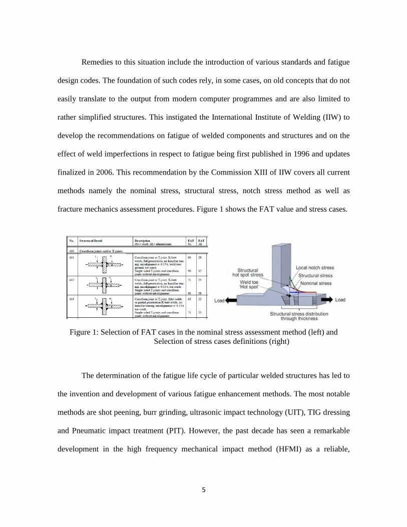
operators. Figure 2 shows the complete set of HFMI/PIT.
Figure 2: Complete equipment set of HFMI/PIT

9
For ensuring the good quality resulted by treatment process, the intensity of device
should be checked and measured regularly using special-designed intensity test prior to
any application. A proposal for procedures and quality assurance for HFMI treated welded
joints in steel was developed by PITEC GmbH to apply on steel structures with plate
thicknesses ranging from 5 to 50 mm and for yield strengths from 235 to 960 MPa by
Marquis and Barsoum [6]. Figure 3 shows the device for intensity test of device.
Figure 3: Intensity test (Almen Test) developed by PITEC GmbH
To achieve outstanding quality result, HFMI/PIT’s quality monitoring guidelines
with reference to the recent proposed procedures and quality assurance guidelines for
HFMI-treated joints are established by Gerster et al. [7]. Figure 4 exhibits the technique to
assure the quality of HFMI/PIT-treated surface.

10
Figure 4: Suitable quality assurance technique using digital/analog magnifier
Compared to conventional quality assurance method using depth gauge or caliper
to measure the groove depth (normally max. 2mm), the quality monitoring technique for
HFMI/PIT is carried out through visual inspection using digital or manual magnifier to
ensure that no rest notch is available on treated surface. The decision on “no rest notch”
surface inspection instead of just measurement of groove depth is due to following reasons:
(i) no single groove dimension is optimal in all situations, (ii) material hardness at the weld
toe may vary and hence treatment needs to be systematically adapted, (iii) deeper undercut
is allowed based on quality standard (ex. ISO EN 5817, refer Table 1) and (iv) strong weld
reinforcement possesses deep transition groove.
Table 1: Limits for imperfections for quality level

11
To ensure the good quality result, proper procedure for operator can be developed.
This step-by-step operation procedure is named as HFMI/PIT Treatment Procedure. Figure
5 shows an example of treatment procedure.
Figure 5: HFMI/PIT treatment procedure
HFMI/PIT is capable to be applied at atmospheric and in underwater condition. For
underwater treatment, the components are made of CrNi-alloy against corrosion and the
casing including holes and channel is manufactured by using rapid prototyping. A special
seal is also designed against water entrance into the system. In order to avoid the blowing
effect to the front side, a special designed component is developed which also ensures the
pressure balance inside the portable gun system. Figure 6 shows the underwater weld
treatment.

12
Figure 6: Underwater treatment process using HFMI/PIT
2.2 RESEARCH RESULTS AT UNIVERSITIES & RESEARCH INSTITUTION
The past decade has seen several researches being conducted on the possible
improvements of the fatigue life cycle using HFMI/PIT. Post-treatment techniques like the
high frequency mechanical impact treatment (HFMI) exhibit a significant fatigue life
enhancement of welded joints. In general this effectiveness is primary based on three
effects, whereas the notch stress concentration at the weld toe is reduced, the local
hardness increased and compressive residual stresses are induced.
At University Stuttgart in Germany, Kuhlmann [8] investigated experimentally the
fatigue improvement peened by newly-developed HFMI/PIT. The investigation was
carried out on material S355J2 and S690QL welded as butt and cruciform joint. It can be
seen from the test report that the fatigue improvement factor (mean value) is 2.22 for 355

13
(cruciform joint), 1.82 for S690 (cruciform joint) and 1.38 for S355 (butt joint). Figure 7
shows the S/N curves as results of investigation.
Figure 7: Results of S/N curves for S355 (cruciform joint, left),
S690 (cruciform joint, right) and S355 (butt joint, below)
For Bundesanstalt fuer Wasserbau or BAW (Federal Waterways Engineering and
Research Institute) in Germany, a research [9] was conducted under collaboration between
University of Stutgart and Karlsruhe Institute of Technology to investigate the effect of
HFMI/PIT on fatigue strength improvement of mild steel (S235). Due to the lack of
research on commonly used low carbon steel, this research was initiated and finalized in
March 2013. In this investigation, there were four (4) trials which can be shown in the
Table 2.

14
Table 2: Results of research at BAW
Trial Treatment Process Fatigue Strength [in MPa]
at N=2.106 cycle
1 Welded - untreated 81.4 (m=3.0)
2 Welded – treated 182.3 (m=11.8)
3 Welded – cyclic loaded - treated 105.9 (m=4.72)
4 Welded - cyclic loaded till crack –
repair welding - treated
87.6 (m=4.27)
At Belgian Welding Institute (BWI), an extensive investigation [10] was
established in 2014. In this project, BWI investigated methods to improve the fatigue
properties of welded joints in high strength steels (HSS) and this by different means. Two
re-melting techniques (TIG- and Plasma dressing) and one mechanical technique
HFMI/PIT were applied and compared. The general objective was to develop high
performance welded joints in HSS in a thickness range of 5 – 10 mm with improved
fatigue properties. This investigation clearly shows the potential of the post-weld treatment
techniques. In Table 3, the increase in FAT class of dressed stiffeners and HFMI/PIT
treated stiffeners compared to the current FAT class of 56 of Eurocode III (m=3) is listed.
Table 3: Results of research at BWI
Steel Grade Thickness (mm)
Effect of Dressing (m=3) in %
Effect of HFMI/PIT (m=5) in %
S420MC 5 +29 +93
S420MC 10 +46 +86
S700MC 5 +61 +109
S700MC 10 +9* +170 *Results are based on small quantity of specimens.
At the University of Duisburg-Essen in Germany, Berg and Stranghoener [11]
performed fatigue tests on four different welded details made of ultra-high strength steels

15
S960, S1100 and S1300 to determine the influence of HFMI/PIT on the fatigue strength.
The fatigue strength of HFMI/PIT treated specimens was at least twice the fatigue strength
of the as welded toe condition. Figure 8 shows the result for different joint types.
Figure 8: Comparative test results of HFMI peened on weld toe
At University of Aalto in Finland, Yildirim and Marquis [12] perceived that the
fatigue strength of improved welds increases with material yield strength. A design
recommendation including one fatigue class increase in strength (about 12.5%) for every
200 MPa increase in static yield strength is proposed and are shown to be conservative
with respect to all available data. Figure 9 shows the increase of FAT value based on yield
stresses.
Figure 9: FAT classes as a function of the fy

16
At Montan University in Austria, the effect of HFMI/PIT for mild structural steel
(S355) up to ultra-high strength steel (S960) on fatigue was investigated by Leitner at al.
[13] and it is concluded that the base material stress range can be reached for the high-
strength steel joints with HFMI treatment while all fatigue test data points are above the
IIW- recommendation, even if a bonus factor of 1.5 for HFMI treatment and a Benign
Thinness bonus factor are considered. Figure 10 shows the influence of HFMI/PIT and
yield strength on fatigue cycle.
Still at Montan University, Simunek et al. [14] developed a simulation loop set-up
including structural welding simulation, numerical computation of the HFMI/PIT-process,
and finally, a numerical estimation of the local fatigue behaviour using FEM to compare
the benefit of HFMI/PIT-treatment. Leitner et al. [15] examined the effect of variable
amplitude loading on the fatigue strength of HFMI/PIT-treated T-joints. Constant fatigue
tests for welded T-joint specimens present a high potential of the HFMI/PIT-treatment to
enhance the fatigue behaviour of welded steel structures. Additional variable amplitude
tests showed a significant difference in the evaluated fatigue strength. Figure 11 shows the
results of stress distribution using FEM.

17
Figure 10: Influence of base material yield strength on fatigue cycle
Figure 11: Stress distribution and plastic deformation
at the weld toe using the developed simulation loop
At KTH – Royal Institute of Technology in Sweden, a comprehensive evaluation of
published data for welded joints which had been improved using high frequency
mechanical impact (HFMI) treatment was conducted in by Yildrim et al. [16] with
proposed sets of characteristic fatigue strength curves as functions of yield strength. All of
the design curves proposed are conservative with respect to available fatigue test data.

18
Figure 12 shows experimental data for non-load carrying HFMI-treated weld based on
different yield strength.
Figure 12: Experimental data for non-load carrying HFMI-treated welds based
on HSS. Proposed characteristic curves for: (a) 235 < fy < 355, (b) 355 < fy < 550, (c) 550
< fy < 750 and (d) 750 < fy < 950
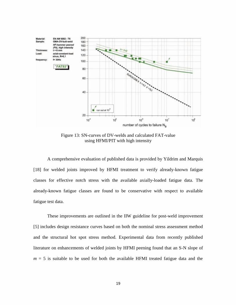
At University of Braunschweig in Germany, Pagel et al. [17] investigated the
influence of the high intensity on the fatigue strength of aluminum welds with HFMI/PIT
and revealed that the fatigue strength of welded aluminium joints can be improved
significantly with help of this method. Figure 13 shows the comparative S/N curves
between experiment and EUROCODE 9.
19
Figure 13: SN-curves of DV-welds and calculated FAT-value
using HFMI/PIT with high intensity
A comprehensive evaluation of published data is provided by Yildrim and Marquis
[18] for welded joints improved by HFMI treatment to verify already-known fatigue
classes for effective notch stress with the available axially-loaded fatigue data. The
already-known fatigue classes are found to be conservative with respect to available
fatigue test data.
These improvements are outlined in the IIW guideline for post-weld improvement
[5] includes design resistance curves based on both the nominal stress assessment method
and the structural hot spot stress method. Experimental data from recently published
literature on enhancements of welded joints by HFMI peening found that an S-N slope of
m = 5 is suitable to be used for both the available HFMI treated fatigue data and the

20
existing data for hammer peened welds. Fatigue strength improvement factors in all of
fatigue design methods for HFMI improved welds are defined at N = 2x10⁶ and on an
assumed S-N slope of m = 5. Because the S-N lines in the as-welded state follows a slope
m = 3 and, after HFMI treatment, the slope is changed to m = 5, the computed
improvement in fatigue strength changes as a function of N. The FAT value after HFMI
treatment for the cruciform joint shows an increment factor of 1.91 for a survival
probability of 95% and an increment factor of 2.38 for a survival probability of 50%. [19-
22]. Haagensen [3], Yildirim and Marquis [23] and Maddox [24], had observed that the
degree of improvement for HFMI treated and hammer peened welded components
increases with material strength.
2.3 HFMI/PIT-APPLICATIONS AT VARIOUS INDUSTRIES
Various industrial applications [7] have been conducted with the purpose of not
only for fatigue strength improvement but also for mitigating the weld induced distortion.
Linde Engineering in Schalchen, Germany [26] investigated the effect of HFMI/PIT on
distortion of butt-welded plate with base material of P265GH. It was found out that the
distortion can be reduced up to more than 30%. Figure 14 shows the effect of HFMI/PIT
on weld distortion.

21
Figure 14: Weld induced distortion without (left) and with (right) HFMI/PIT
TUV SUD Industry Service in Mannheim, Germany cooperated with technology
developer for implementing HFMI/PIT within the scope of EUROCODE EN1993-1-9. It is
concluded that the user or customer can benefit by using HFMI/PIT on fatigue life
enhancement, simple maintenance concept, “slim” design and design optimization [27].
DCC Doppelmayr Cable Car GmbH applied HFMI/PIT to increase the life time of
steel construction including tubular joints at the Oakland Airport in California. Due to the
strict regulation for fatigue strength in USA, several fatigue tests were conducted prior to
application under collaboration between University of Stuttgart in Germany and University
of Seattle in USA. It is claimed by both universities that the lifetime is increased up to 4.5
times compared to as-welded condition. Figure 15 exhibits the tubular joint construction
treated by HFMI/PIT.

22
Figure 15: Application of HFMI/PIT on tubular joint construction.
At Max Planck Institute for Plasma Physics in Germany, HFMI/PIT was used in
the nuclear fusion reactor “Wendelstein 7-X” to reduce tensile residual stress on each weld.
The base material was austenitic steel 1.4429 and filler metal material was 1.4455. The
construction started in 2009 and was accomplished in 2014. The PIT treatment is mainly
used during the welding of many supports from the inner to the outer vessel wall. Figure
16 shows the plasma vessel under construction and the PIT treatment of each bead to keep
the tensile stresses generated during welding to a minimum level.
Figure 16: Application of HFMI/PIT in the project “Wendelstein 7-X”

23
At SMS Siemag, HFMI/PIT was used to enhance the life time of ladle turret which
is used for continuous casting. Based on the numerical calculations, the "hot spots" of the
system were defined for the post-treatment. Figure 17 shows an example of ladle turret
with welded structure.
Figure 17: Application of HFMI/PIT in Laddle Turret for continuous casting
At a train manufacturer in Austria, HFMI/PIT was used to enhance the fatigue life
after repair welding for boogie section. It was recorded that at 3.2 million load-cycles
cracks occurred which was repaired without HFMI/PIT-treatment. After 100,000 load-
cycles, this section failed due to crack. Afterwards, each layer was repaired by using
HFMI/PIT and no further crack was found. After 8.4 million load-cycles, a crack occurred
on the opposite side at a stiffening rib. After 12 million load-cycles, the experiment was
terminated. Figure 18 shows the weld treatment using HFMI/PIT and test facility for
analyzing fatigue of boogie.
Figure 17: Weld treatment using HFMI/PIT on train bogie and test facility

24
Other industrial applications of HFMI/PIT include:
Innovative maintenance in steel manufacturer Steel bridge
Tower of wind energy plant Duplex mixer shaft
Crane manufacturer Compressor damper
Component of Press Machine Steam boiler
Turbine housing Crane Structure
Ship building Mass Rapid Transit (MRT)
Roller shaft maintenance Etc
Figure 17: Other examples of industrial application using HFMI/PIT
3.0 WELD FATIGUE INTEGRITY – A NEW RESEARCH CLUSTER AT
AMTEx UiTM SHAH ALAM
Since 2013, Advanced Manufacturing Technology Excellence Centre a.k.a AMTEx
at Faculty of Mechanical Engineering in UiTM Shah Alam has pioneered a new research
cluster stressed on Weld Fatigue Integrity which covers 5 sub-clusters as shown in Figure
18.

25
Figure 18: Weld Fatigue Integrity and sub-clusters
In sub-cluster 1, AMTEx attempts into advanced welding process using robotic
welding and friction stir welding (FSW) as well as into optimization method of welding
parameters using design of experiment (DoE). This will lead to the experimental
investigations on weld discontinuities, temperature distribution, distortion, fatigue life and
residual stress. Sub-cluster 2 focuses on the modelling and simulation of welding process
for predicting the induced distortion and residual stress using FEM software Simufact
Welding. In sub-cluster 3, weld design and fatigue life are modeled and simulated using
FEM. One of the objectives is to determine the hot spot stress and hence to estimate the
total life of the structure.
26
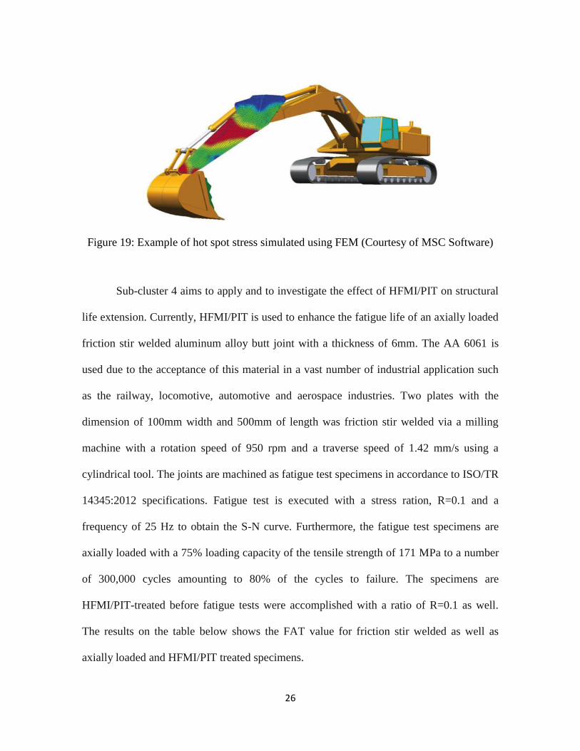
Figure 19: Example of hot spot stress simulated using FEM (Courtesy of MSC Software)
Sub-cluster 4 aims to apply and to investigate the effect of HFMI/PIT on structural
life extension. Currently, HFMI/PIT is used to enhance the fatigue life of an axially loaded
friction stir welded aluminum alloy butt joint with a thickness of 6mm. The AA 6061 is
used due to the acceptance of this material in a vast number of industrial application such
as the railway, locomotive, automotive and aerospace industries. Two plates with the
dimension of 100mm width and 500mm of length was friction stir welded via a milling
machine with a rotation speed of 950 rpm and a traverse speed of 1.42 mm/s using a
cylindrical tool. The joints are machined as fatigue test specimens in accordance to ISO/TR
14345:2012 specifications. Fatigue test is executed with a stress ration, R=0.1 and a
frequency of 25 Hz to obtain the S-N curve. Furthermore, the fatigue test specimens are
axially loaded with a 75% loading capacity of the tensile strength of 171 MPa to a number
of 300,000 cycles amounting to 80% of the cycles to failure. The specimens are
HFMI/PIT-treated before fatigue tests were accomplished with a ratio of R=0.1 as well.
The results on the table below shows the FAT value for friction stir welded as well as
axially loaded and HFMI/PIT treated specimens.

27
Table 4: Results of HFMI/PIT application at AMTEx UiTM
Lastly, sub-cluster 5 is dealing with a new development of “WeFit Project Plan”
which consists of following steps: (1) Fatigue strength analysis, (2) Life extension plan, (3)
Risk based inspection plan and (4) Weld fatigue monitoring.
4.0 CONCLUSION
Life extension, as a part of asset integrity management which is essential for
ensuring a safe and sustainable industry, involves maintaining hardware to be safe, reliable
and efficient. Especially for offshore oil and gas installations, which are supposed to be
constructed to last for decades, are frequently situated in challenging environments and are
vulnerable to extreme weather and operational conditions. Hence, maintaining asset
integrity is a challenge which oil and gas industry should take seriously. Moreover, asset
integrity forms a key part of in safety’s strategy.
Finally, the review on researches and applications can be summarized as follow:
In general, high fatigue strength of welded structure can be achieved by: (1) Good
design practice, (2) High quality fabrication and (3) Improvement method.
Peening technology as improvement method is already recognized by numerous rules
and standards such as ABS and AWS to control shrinkage stresses, prevent cracking
and mitigate distortion.
Type FAT value
Base Material (AA 6061) 140 MPa
Friction Stir Welded (as-welded) 86 MPa
Axially loaded + HFMI/PIT treated 112 MPa
28
New improvement method HFMI/PIT can increase fatigue life, fatigue strength and
stress corrosion resistance.
HFMI/PIT can be used for preventive and corrective maintenance or for rehabilitation
and repair (atmospheric and underwater).
HFMI/PIT can be used for optimization of new design and material usage.
HFMI/PIT can be used on layer-by-layer welding to reduce residual stress and
distortion.
HFMI/PIT can be carried out based on FEM, past experiences or weld/suspect details.
HFMI/PIT strengthens metals through cold work which can increase surface hardness
providing increased resistance to wear and abrasion.
Selection of HFMI devices is essential such as quality assurance methods
(certification, inspection method), safety awareness, working potential/voltage (esp.
for confined or wet area).
Various applications of HFMI were reported ranging from offshore (duplex flow line,
pontoon, aging rigs, FPSO, ship-shaped FPU etc), underwater structure, stainless steel
boiler, train bogies, cranes, highway bridge up to heavy industrial crankshaft.
ACKNOWLEDGEMENT
The authors would like to express their gratitude to staff members of Welding
Laboratory and Advanced Manufacturing Laboratory at Faculty of Mechanical
Engineering in UiTM Shah Alam for their support. A special thank is also directed to
PITEC GmbH in Germany for providing the equipment and encouraging the team of Weld
Fatigue Integrity with new knowledge and experience. Last but not least, the authors would

29
like to thank all supporting companies (Nusantara Technologies Sdn. Bhd., Calidad Sdn.
Bhd, Castral Sdn. Bhd., Bogor Safety Institute and MSC Software Corporation) for
providing welding specimens, test facility, standards and advices during the fatigue test
and simulation process.
REFERENCES:
1. A. Hobbacher, Recommendations for Fatigue Design of Welded Joints and
Components, International Institute of Welding-IIW, document XIII-2151-07/XV-
1254-07. Paris, France, May 2007.
2. S. J. Maddox, 2003 IIW Portvin lecture: Key developments in the fatigue design of
welded constructions. IIW Annual Assembly, (2003) PDCA12-70 data sheet, Opto
Speed SA, Mezzovico, Switzerland.
3. P. J. Haagensen, S. J Maddox, IIW Recommendations on Post Weld Fatigue Life
Improvement of Steel and Aluminium Structures, International Institute of
Welding, Paris, 2010.
4. Key Programme 4 (KP4), Ageing and life extension programme, a report by the
Energy Division of HSE’s Hazardous Installations Directorate (Internet source:
http://www.hse.gov.uk/offshore/ageing/kp4-programme.htm).
5. IIW Fatigue Recommendations XIII-2460-13/XV-1440-1 2013.C.
6. G. Marquis and Z. Barsoum, Fatigue strength improvement of steel structures by
high-frequency mechanical impact: proposed procedures and quality assurance
guidelines, Welding in the World, vol. 58, no. 1, pp. 19–28, Jun. 2013.
7. P. Gerster, F. Schäfers, and M. Leitner, Pneumatic Impact Treatment (PIT) –
Application and Quality Assurance, IIW Document XIII-WG2-138-13 pp. 1–11.
8. U. Kuhlmann, Test Report: Investigations on the fatigue strength improvement of
welded joints using Pneumatic Impact Treatment (PIT), University of Stuttgart,
2013.
9. U. Kuhlmann, T. Ummenhofer and U. Gabrys, Untersuchungen zur Anwendung
höherfrequenten Hämmerverfahren im Stahlwasserbau, Test Report for BAW
(Bundesanstalt fuer Wasserbau), 2014.
10. Belgian Welding Institute, Summary of the results of the research project:
Improvement of welded structures fatigue life in high strength steel grades
(DURIMPROVE), Belgium, 2014.
11. J. Berg and N. Stranghoener, Fatigue Strength of Welded Ultra High Strength
Steels Improved by High Frequency Hammer Peening, Procedia Materials Science,
vol. 3, pp. 71–76, 2014.

30
12. H. C. Yildirim and G. B. Marquis, Fatigue strength improvement factors for high
strength steel welded joints treated by high frequency mechanical impact,
International Journal of Fatigue, vol. 44, pp. 168–176, 2012.
13. M. Leitner, M. Stoschka, and W. Eichlseder, Contribution to the fatigue
enhancement of thin-walled, high-strength steel joints by high frequency
mechanical impact treatment, IIW Document XIII-2416-12pp. 1–15. D.
14. D. Simunek, M. Leitner, and M. Stoschka, Numerical simulation loop to investigate
the local fatigue behaviour of welded and HFMI-treated joints, XIII-WG2-136-13
pp. 1–13.
15. M. Leitner, S. Gerstbrein, M. J. Ottersböck, and M. Stoschka, Fatigue Strength of
HFMI-treated High-strength Steel Joints under Constant and Variable Amplitude
Block Loading, Procedia Engineering, vol. 101, pp. 251–258, 2015.
16. H. C. Yildirim, G. B. Marquis, and Z. Barsoum, Fatigue assessment of high
frequency mechanical impact (HFMI)-improved fillet welds by local approaches,
International Journal of Fatigue, vol. 52, pp. 57–67, 2013.
17. Th Nitschke-Pagel, H Eslami, Klaus Dilger, Influence the deformation intensity on
the fatigue strength of aluminium welds with different mechanical surface
treatments, International Institute of Welding, IIW-Doc. XIII-2483-13 pp. 1–14.
18. H. C. Yıldırım and G. B. Marquis, Fatigue design of axially-loaded high frequency
mechanical impact treated welds by the effective notch stress method, Materials &
Design, vol. 58, pp. 543–550, 2014.
19. G. B. Marquis, E. Mikkola, H. C. Yildirim, and Z. Barsoum, Fatigue Strength
Improvement of Steel Structures by HFMI: Proposed Fatigue Assessment
Guidelines. IIW doc. XIII-2452r1-13.
20. G. Marquis and Z. Barsoum, Fatigue strength improvement of steel structures by
high-frequency mechanical impact: proposed procedures and quality assurance
guidelines, Welding in the World, vol. 58, no. 1, pp. 19–28, 2013.
21. G. Marquis and Z. Barsoum, Fatigue strength improvement of steel structures by
high-frequency mechanical impact: proposed procedures and quality assurance
guidelines, Welding in the World, vol. 58, no. 1, pp. 19–28, 2013.
22. G. Marquis, and Z. Barsoum, Fatigue Strength Improvement of Steel Structures by
HFMI: Proposed Procedures and Quality Assurance Guidelines, International
Institute of Welding, Paris, IIW Document XIII-2453-13, 2013.
23. H. C. Yildirim, G. B. Marquis, and Z. Barsoum, Fatigue Assessment of High
Frequency Mechanical Impact (HFMI) Improved Fillet Welds by Local
Approaches, International Journal of Fatigue, vol 52, pp. 57-67, 2013.
24. S. J. Maddox, M. J. Dore, S. D. Smith, Investigation of ultrasonic peening for up-
grading a welded steel structure. International Institute of Welding, Paris, IIW Doc.
XII-232610, 2010.
25. Linde Engineering Division, Einfluss des Haemmerns auf die Nahtschrumpfung,
Germany, 2010.
26. TUV SUD Industrie Service GmbH, Einfuehrung des Eurocodes und
Lebensdauerverlaengerung von Schweisskonstruktionen/Komponenten durch
qualifizierte mechanische Nachbehandlung, Mannheim, Germany, 2014.


![[Files.indowebster.com]-Geology Handout Geologi Dasar 2010 Salahuddin Hussein 2009](https://static.fdocuments.us/doc/165x107/55cf9a1a550346d033a07c5a/filesindowebstercom-geology-handout-geologi-dasar-2010-salahuddin-hussein.jpg)