LIFE CYCLE COST FOR DRAINAGE STRUCTURES,cme•srted with the clay pipi durability guidelines. The...
72
TECHNICAL REPORT GL-68-2 LIFE CYCLE COST FOR DRAINAGE STRUCTURES, by John C. Potter Geotechnical Laboratory 0 DEPARTMENT OF THE ARMY Waterways Experiment Station, Corps of Engineers PO Box 631, Vicksburg, Mississippi 39180-0631 S February 1988 Final Report Appmad For Pubic RsNm 0OUAW~io UmLWWOd DTIC SEL\IECTE D H Ps 'DEPARTMENT OF THE ARMY US Army Corps of Engineers Washington, DC 20314-1000 88 4 11 359
Transcript of LIFE CYCLE COST FOR DRAINAGE STRUCTURES,cme•srted with the clay pipi durability guidelines. The...

TECHNICAL REPORT GL-68-2
LIFE CYCLE COST FOR DRAINAGE STRUCTURES,by
John C. Potter
Geotechnical Laboratory
0 DEPARTMENT OF THE ARMYWaterways Experiment Station, Corps of Engineers
PO Box 631, Vicksburg, Mississippi 39180-0631
S
February 1988Final Report
Appmad For Pubic RsNm 0OUAW~io UmLWWOd
DTIC
SEL\IECTE DH
Ps 'DEPARTMENT OF THE ARMYUS Army Corps of EngineersWashington, DC 20314-1000
88 4 11 359
Destroy this report when no longer needed. Do not return
It to the originator.
4,
The findins in this rep*t are not to be construed as an otficialDepartment of the Army position unless so designated
by other authorisd documents.
The contents of this report ar" not to be used foradvertising, publication, or promotional purposes.Citation of trade names does not constitute anofficial endorsement or approval of the uso of
such commercial products.

aL - OYGA~SS ATIOI AUTPOMM 3~iI5 0STMOW9TORN / OVUGABZTY OF REPOTNuAR)
POWORW 0W5A# A0VPWT#I K~jF 9- WOTOEO IVSS eNM 9MORIGOGANIZArNIKT NUO#4 S
Gootecha~leal Laborator CZME-GP-DE
PO Ift 631YFietaburg, W "49180-3631
- pp ym 9 PNOWNWMNT *dThuMt#4? iOENTIUIATo# wknUd
20 Nameacbestts AvenueELEMNT NO0 No.N.os .
LU. 1.l Cost for Drain. structures
ftetler Johm C.
final rosomt rpan-meiL -- " abir l8
Avoilacolditioms mateios i trea-iIngth rmatrian durabilit, c25 ort, Roald tyeoad cinlfitbein
factm. TI s cfst hlDrbenth e toaoirl pos fte alrntvovrisr-
jscted~ ~ ~ :1 lif orlfeyl ca gLC. UlesostheLCi osdrdoe is ot h
soile condiinot be asure oftrengiti, material vuabllufohi. constut.o and maeo fiintyeinanc
dollars. Except for determining a service life for the various type; (materials) ofdrainage structures, the procedure. for LCC amalysir, are well established. LCC based *co-nowic stuqdiea 6ate an into,,gral part of the ccuplete design process and are a requirement
* specified In Technical Manual 3-402-1. AR 11-28/AnR 178-1 Sives the basic criteria andstandard* for economic studies by and for the Departments of the Army and Air Force. The
(Continued)
*UftOAJSWGinAWmUDg C SAME AS RPT Oi SR ___________
P" 1M X a 0 eamu a 36aftSFCURITY CLASSIF"CTION OF TMuS PACAUnclassified

-mm/
is. AletmCT (Cestlaed).
gldellses presented I* Part II of this report can be used to ,stimato the service life of
a perticular doeip a-. mmure a 50-year service life. Thus, the procedures for economicmalysin deeculbed in Tchnica] manual 5-802-1 can be used to determine LCC. The alterna-t:lts con tbem be order rasked bosed on LCC. aid the best design can be retionally andcoai-deatly selected.
AGOONuIes per"IS! GRAkiOTIC tADIUMMoMood C)
Distribtil on/
Availability Co*do*
1n landn/ r
S9CUMTT C6AUSIfCATION OP 1WIS IAGE

rAEFACE
The tivestigation raported herein was sponsored by the Office, Chief of
Rug-nmwrs (OCR). under the work effort "Life Cycle Cost for Drainage Struc-
tures (Pipe)," of the Facilities Investigation and Studies Program. The OCE
Tevenlcal Monitor w~s Mr. Edwin Dudka.
The study was conducted at the US Army Engineer Waterways Experiment
Station (VIS) from November 1985 through Snpteuber 1987 by the Pavement Syti-
toe Division (PSD) of the WES GeotechnicA Laboratory (GL).
The revearch was conducted and the report was written by Dr. J. C.
Potter, Ml. The study was under the supervision of Messrs. H. H. Ul.ery, Jr.,
Chief, PSD; H. Green, Chief, Engineering Analysis Group, PSD; and D. h. Ladd,
Chief, Criteria Development Unit, PED. The work was conducted under the gen-
etal suMervision of Dr. W. F. Marcuson III, Chief, GL. The report was edited
by Ns. 0dll F. Allen, Information Products Division, Information Technology
Laboratory.
Ce nts on the durability guidelines were solicited from Industry asso-
ciations and corporations. Specifically, the guidelines for metal pipe were
*enu to the Nataonal Cozaagated Steel Pipe Association, the Aluminum Associa-
tion, and Arsco. The concrete 'ipe guidelines were sent to the American
Cocreta Pips Association. Unibel.], the po!yviny1 chloride (PVC) pips manu-
fact'zrers association, the Plastics Pipe Institute, the polyethylene pipe
mMufacturers association, and Advanced Drainage Systems (ADS) Inc., a major
polyethylene pipe manufacturer, received copies of the plastic pipe guide-
lanes. The National Clay Pipe Institute was consulted on clay pipe
durability.
Responses vere received from both associations and corporations. Coin-
sents on metal pipe durability came from the National Corrugated Steel Pipe 4
Association, the Aluminum Association, Areco, Bethlehem Steel Corporation,
Pacific Corrugated Pipe Co., Lane Enterprises, Caldwell Culvert Company, and
Dow Chemical. The American Concrete Pipe Association, the Ohio Concrete Pipe
Msnufacturers' Association, and the Ohio Department of Tran:=portation com-
mented on the concrete pipe guidelines. The plastic pipe design procedure
described in this report is based on the industry-consensus ef American Asso-
ciation of State •ighway and Transportntion Officials (AASHTO) proposed spe-
cifications, to which Unibell, the Plastics Pipe Institute and ADS have
1.s

mtrtibutsd. Connte were also received separately from Unibl, Contech,
thw Plastics Pipe Institute abd AL•. The National Clay Pipe Institute has
cme•srted with the clay pipi durability guidelines.
The respeuses noted above vere studied vich additional research as" •s*e~ary to resolve conflicts. The guidelines were thfin revised as
GOL Dwayne G. Lee, CZ, was the Commander and Director of WES during theproartattn sand publication of this report. Dr. Robert W. Whalin vas
2eclmieil Director.
2
I a R e a .. ~ a . . ,.. 1 a¶J a A -f

Scowrurmrs
page
ftZYAC19 ........ ........ ........ .. ... . . . . . . . . . . . . . . . I
S00ERSION FACTORS, ON-SI TO SI (METRIC)OTS OF MEASURDEMET .............................. 4
PART I: INTRODUCTION . . ........ . 5
Pu p s .............................. ............ ....... : 5Sckgv* ................................... 6
PART II" SERVICE LIFE GUIDELINES ...... .................. .......... 7Ge e a ..... .. o ... oi ..... ..... ..... ..... ..... o o' .. ...o .o' 7 'eratl Pip. ........ .... 37
8,,,fter , Pipe.. . . . . . . . . - -- ... . . . . .... .. o27. 1
PART III: LIFe C....... COST .k.(...)OG ............................. 28
Cnalysis .....r..... ............. ..... . ......... 29Aummal y8 8 P r o .... o ............................... o - .. o............ 27
CoAaR ............. *a*.. .. *M. -................. o........... 30Ge conera ... o ..................... o.................. ...--......... is
CoAlutin Proent Worth. ................... ....................... 32DeC tson Criteria .......... ............................. ........ 32Discount Rate . . . .... .... o............. . ...... o... -......... 35
utinry *..... W....t..... ........................ 37Dec n a ..... o . ....- , .. 3
EFRxemCElS .............. ....... ... ................ 39
BIBLIOGAMu - .... ... .. ...................................... - .... 42APPENDIX A: PROPOSED AASHTO DESIGN PROCEDUR.' ........................... Al
3

CO•KYRSION FACTORS, NON-SI TO SI (METRIC)UNITS OF MEASUREMENT
Woe-SI unite of nessurem~nt can be converted to SI (metric) units as folloes:
N~t~ply .By To Obtain
feett.t r 08
inches 2.54 centimetres
kipe (force) 4.448222 kilonevtons
011e6 (US statute) 1.609347 kilowetres
Founad (force) per 6.894757 kilopascals8q"ar6 Inch
posado (moo) per 16.01846 kilograms per cubic metrecubic foot
eqmuae Loch** 6.4516 &quare centinetres
r

LITE CYCLE COST FOR DRAINAGE STRUCTURES
PART I: INTRODUCTION
.Bac!Around
1. WMay factors are involved in the desig" of drainage systems. Prin-
cipal factors are hydrology, soil conditions, _..erial strength, material
durability, cot.', and type of facility or site being drained. While not
ascesearily overriding, the cost is often one of the most important factors.
This cost should be the total, overall cost of the alternative over its pro-
jtct#e life, or life cycle cost (LCC). Unless the life cycle cost is consid-
r"d over fl-vt cost, the owner cannot be assured of receiving maximum value
for his construction and maintenance dollars. LCC based economic studies are
an Integral part of the complete design process and are a reqviiresent speci-
fied by Technacal Manuel 5-802-1. AR 11-28/AnR 178-1 gives the basic criteria
and standards for economic studies by and for the Departments of the Army and
Air Force.
Purpose
2. The purpose of this report is to provide supplemental guidance in
performing LCC studies to determine the relative economic ranking of alterna-
tlve d-ainage systams uuing pipes fabricat*4 from various construc'tion materi-
als. Current Corps of Engineers design criteria do not include guidance ior
oentimting the expected service life for drainage structures. Therefore,
guidance in determining the appropriate service life for a particular design
alternative is included in addition to the supplemental guidance on economic
calculations. _I
Scope
3. This report provides supplemental information required to perform
LCC analyses of military drainage structures to determine the relative
economic rating of design alternatives. Methods of estimating service life or
5I

in-_• u a paroicular design life are aleso given for the more common pipe
eus atols i.od in draimagn structures. Metal, concrt-Le, clay, and plastic
pipe dftability guidelines are prodided. including ',rocedurgs for estilating
the service life of steel &nd concrete pipes.
61

PART II: SERVICE LIFE GUIDELINES
General
4. The most difficult and controversial aspect of life-cycle cost anal-
ysis (LCCA) for drainage structures is establishing a service life for each
material type. Service life is a function of pipe material, the environraent
In which it is installed, and the effeot of additional measures taken to pro-
tect the pipe from deterioration. Servicg life is also subject to biased
estimtion b7 investigators working in particularly harsh or mild envirvnments
and by sonm vendors and trade associations. ICCA requires a realistic esti-
mate of saervice life. So. currently available performance data ,nd durability
guldelines from various sources outside of the Corps of Engineers have been
collected, analyzed, and synthesized into a comprehensive but uncomplicated
procedure. Guidelines for predicting a smrvice life or -nsuring a particular
design service life for the more common types of pipes found in drainage
structures were developed and included in this report.
Metal Pipe
5. Metal pipe performance data and durability models based on this per-
forwane can b' found in the "Huandbook of Sotal Drainaga and High-w--- Cona-truc-
A'ion Products," (American Iron and Steel Institute (AISI) 1983), "Durability
of Drainage Pipc," (Transportation Research Board 1978), and various technical
papers such as those found in "Symposium on Durability of Culverts and Storm
Dr-sins" (Transportation Research Board 1984) and those listed in the
bibli ography.
6. The information contained in these resources has been synthesized
into a flexible and coherent durability guide, consisting of two sections.
The first section is a set of guideline- which establish environmental lints
for satisfactory performance of metal pipe for at ieast 50 years. These
guidelinee encompass the majority of drainage applications. For applications
in environments outside of these limits or when a service life of other than
50 years is desired, a second section is provided. Using this section, a
combination of metal pipe and proteczive coatings can be designed to give a
wide variety of service lives over a wide range of environmental conditions.
7
~ - mP~M~ ~ A~'A ~f F~ft 'I i
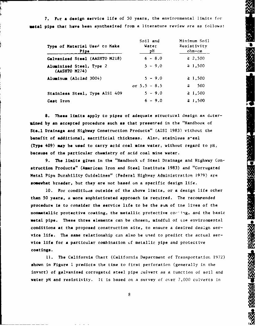
7. Fur a design service life of 50 years, the environmental limits for
ntal pipe that have been synthesized from a literature review are as followa:
Soil and Minimum SoilT ype of Material Used to Kake Water Resistivity
Pipe pH ohm-cm
Galvanized Steel (AASHTo M218) 6 - 8.0 Z 2,500
Aluminized Steel. Type 2 5 - 9.0 Z 1,500(AASHTO M274)
Aluminum (Alclad 3004) 5 - 9.0 Z 1,500
or 5.5 - 8.5 a 500
Stainless Steel, Type AISI 409 5 - 9.0 Z 1,500
Cast Iron 6 - 9.0 ? 1,500
8. These limits apply to pipes of adequate structural design as d,;ter-
mined by an accepted procedure such as that presented in the "Handbook of
Ste.l Drainage and Highway Construction Products" (AISI 1983) Without the
benefit of additional, sacrificial thickness. Also, stainless s~eel
(Type 409) may be used to carry acid coal mine water, without regard to pH,
because of the particular chemistry of acid coal mine water.
9. The limits given in the "Handbook uf Steel Drainage and Highway Con-
struction Products" (American Iron and Steel Institute 1983) and "Corrugated
somewhat broader, but they are not based on a specific design life.
10. For conditi6,s outside of the &bove limits, or a design life other
than 50 years, a more sophisticated approach is required. The reconmended
procedure is to consider the service life to be the s'.a of tne lives of the
nonmetallic protective coating, the metallic protective cov'Ing, and the basic
metal pipe. These three elements can be chosen, mindful of Lhe environmental
conditions at the proposed construction site, to ensure a desired design ser-
vice life. The same relationship can also be uied to predict the actual ser-
vice life for a particular combination of metallic pipe and protectivecoatings.
11. The California Chart (California Department of Transportatior. 1972)
shown in Figure 1 predicts the time to first perforation (generally in the
invirt) of galvanized corrugatcd steel pipe culvert as a function of soil and
water pH and resistivity. It is based on a survey of over 7,000 culverts In
81

'-4
_ I01
Ii
)'4V 0
41VAl
El
.Y4
100
2- Iu
0.
z ._ _ _ _ _ _ _ _ _ _ _ _ -4 I
I8Af2 z~~ 9OI-0J~J3 2 ~1
0 V9
__ __ __ __ _ ... ,i to o _j ~ I A P ! . ~ P R'& ~ T.iF ~ V V f A & ~ U 2 V U V V A

California in the 19501a, and is used as a predictor of service life by more
states than any other rational method (Task Force 22, 1988). The AISI (1983)
Chart (Figure 2) is based on the assumptiot. that culverts can continue to
provide servie until most of the invert is lost. This point corresponds to a
totl metal loss approximately twice that corresponding to first perforation.
Therefore, the ATSI service life was assumed to be double the time to first
perforation. However, the assumption of usabla life aftkr perforation is only
appropriate for gravity flow systems installed in a nonerodible granular
bedding. But the Corps of Engineers allows use of silty and clayey sands,
which can be highly erodible, and Corps spillways and through-levee structures
may operatQ an pressure systems. In these cases, the time to first perfora-
tion is Lhe service life. Furthar, a 3tudy of this issue was recently com-
pleted for the California Department of Transportation (CALTRANS) on behalf of
the California Corrugated Steel Pipe Association by Mr. George Tupac (1987).
Hi found that the AISI chart ie appropriate for the upper 2700 of the pipe
circuaference, but not for the invert. He recoended use of the AISI chart
only when the invert is paved. These equations are adjusted for thicker
galvanized pipe by multiplying the life, Y, of the 16-gage pipe by a gage
factor. These factors are:
AUL.U U ALL. 1.UJ n 7e IJ.U nn.J 1).Jn UU
Gage 16.0 14.0 12.0 10.0 8.0
Factor 1.0 1.3 1.8 2.3 2.8
The service life calculated using this method is the average life based on
field data. The actual life of individual installations may vary
significantly.
12. Aluminum-alloy protective coatings provide better protection for
steel pipe then zinc (galvanized) coatings. Long-term field test data (Morris
and Bodnar 1985) suggest that the aluminum alloy coating (Aluminized Type 2,
AASJTO M274) lasts much longer than plain galvanized coatings (zinc,
AASHTO M218). The only quantitative data on the actual field performance of
Aluminized Type 2 Is that contained in the Armco study, so it received close
scrutiny, even though it was published in a refereed journal with technical
discursions. Supporting information and backup data relating to the
10

0
-41
P94
IPOV JOOA*Ul 09JO0

- • • T•-- --,1
peutoemmace of Aluminixed Type 2, which Armco had used in the prmparation of
Ift technical paper or previously prepared for other agencies were also
obtained. An independent analysis did show that for 16 gage pipe in the
mc rec ended environmental rangem, Aluminized Type 2 lasts two to six times
longer than plain galvanized pipe. A comparative factor of two was chosen to
be conservative. Thus, the gage factors for aluminum-alloy protective coat-
Thickness, in. 0.064 0.079 0.109 0.138 0.168
Gage 16.0 14.0 12.0 10.0 8.0
Factor 2.0 2.3 2.8 3.3 3.8
; However, Aluminized Type 2 should not be used for sanitary or industrial sew-
ers to carry saltwater or acid mine runoff, or where heavy netals are present.
The service life of Galvalume (,il-Zn alloy), AASHTO M289 pipe should be calcu-
lated as for plain galvanized p-.*-. Galvalume performs better than galvanized
steel in atmospheric exposures (Zoccola et al. 1978). but insufficieat
published performance data are available to establish this advantage over
plain salvarized pipe under the erocive-corrosive condirions typical of most
drainage installations.
13. Most of the studies to determine aluminum pit-rate are based on
geographical locution and not environmental parameters such as pH and resis-
tivity. However, the avetage pit-rate varies widely over the ranges of pH and
resistivity which are recommend for aluminum pipe and which are found through-
out the Unitod States. Fo example, though New York and Maine have estab-
lished a pit-rate of 0.5 mila per year (mpy), preliminary work by the
Louisiana Department of Transportation and Development (Temple and Cumoaa
1986) has placed the pit-rate as high as 2.0 mpy for resistivities below 1,000
ohm-ca. More extensive data are needed to 3stablish a general procedure forI
estimating alumijum pit-rate.
14. Greator sirvice lives can be achieved by adding the life of an
additional nonmetallic coating to the life calculated for the pipe and metal-
lic coating (American Iron avd Steel Institute 1983). A synthesis of industryI
and Government agency policies and recommendations resulted in the following
conclusions. Bituminous coating and paving adds about 20 to 25 years to the
12

F'9 9181 life of the pipe. A bituminous coating alone (AASHTO M190) adds about
I yeaos for the tyvical case where water-side corrosion is the dominant
SWlsmace. Up to 25 years nay be added if the effluent is noncorrosive and 1soUL-mede corrosion In the critical factor. Note that bituminous coatings are
isapepriate for applicatious where effluents contain petroleum products.
Polymer coatings (AASMTO K246), in Several, add about 10 years to the averageservics life. A quality ethylene acrylic film, though, may add up to 20 yearsto the service life of the base pipe. The most recently published data on the
durability of thiU product cover only 9-1/2 years of exposure. Even using the
wfub1/h.J reports placing the exposure variously at 13 to 15 years, the use
of a life of "30 or more years" requires an extrapolation to more than double
the curteat e&pVriemce, without benefit of any quantitative data on deteriora-
tiae rates. An Increase in the added life attribucable to this promising
preduct is anticipated, as it is proven in field installations. However, cur-
rently available data do not support a life much greater than about 20 years.
15. Effects of abrasion were included in the data used to generate. the
aboe relatiomwhips. Thus, installations with extraordinarily abrasive condi-
time my experience c shorter service life, but this procedure may conserva-
tively underestimate service life in cases where abrasion is not a factor.
16. Abrasion is a fuuction of velocity and bed load. In the absence of
a bed load, abrasion will not be a factor. Also, abrasive materials will not
be trnsported by T'nqus of less than about 5 ft/sec. Theiefore, abrasion is
not a factor at low velocities without regard to bed load. Abrasion is a fac-
tor when abrasive bed loads are present and flow velocities are high enough to
tramsport then. Invert pzotection should be provided when abrasion is
expected to be above the "average" included in the California method. A bed
load containing material larger than sand size, with sufficient transport
velocity, is likely to produce above average abrasion. Under these particu-
larly abrasive conditions, invert protection should also be considered for
aluminum pipe.
Concrete Pipe
17. Concrete pipes may be subject to deterioration from various condi-
tions including freeze-thaw weathering, acid corrosion, sulfate disruption,
velocity-abrasion of thu concrete, and chloride corrosion of the reinforcing
12, .S U* LXR AM UJI uAA UJ•

F eteel. The reinforcing steel in reinforced concrete pipe may also be subject
to cotrosion by sulfuric acid resulting from sulfide generation. tit this
problem only occurs in some sanitLry sewers. I18. Precast concrete pipe is generally of high quality and not subject
to significant freeze-thaw weathering or chloride corrosion. For cast-in-
place structures, the effects of these conditions can be mitigated by ensuiing
adequate compressive strength (4.000 to 6,000 psi initial strength), limiting
the water/cement ratio (to control porosity), and the proper use of
admixtures.
19. Acid attack is usually mild when soil and effluent pH's remain
between five and seven. and the total acidity is less than 25 mg equivalent to
acid per 100 g of soil. No pH related damage has been observed in alkaline
ouviromeats up to a pH of nine (American Concrete Pipe Association 1981).
20. Sulfate disruption comes from the reaction o' sodium, magnesium, or
-alclum sulfates in the soil and ground water or effluent with the calcium
alumina (C3 A) in the concrete, which results in concrete expansion and spall-
Ing. This can occur if sulfates are in solution, if there is a differential
head between tne inside and outside surfaces of the concrete, anid if evapora-
tion is taking place on one of the surfaces to concentrate the sulfides. Typ-
ically sulfate attack can be a problem when the sulfate content exceeds
1,000 parts per million. Under these conditions, use of Type II or Type V
cements will impede deterioration. The Bureau of Reclamation (US Department
of Labor 1975) guideliies shown in Table 1 can be used to control the effects -
of sulfate attack. Other strategies for reducing the deleterious effects of
sulfates from the Bureau of Reclamation include reducing the C 3A content of
the concrete, steam curing, decreasing the absorption factor and increasing Ithe cement content. The California Department of Transportation consider6 a
seven sack six using Type II cement to be equivalent to a mix using the
minimum allowable amount of Type V cement (Transportation Research Board
1978).
21. Abrasion is a function of velocity and bed load. Abrasion is not a
factor when velocities are less than 15 ft/sec. Some additional protection is
required for velocities between 15 and 40 ft/sec if a bed load is present.
This protection may be in the form of increased cement content such as an
eight sack mix, increased concrete cover over reinforcing (typically 1-1/2 In.
and/or harder aggregates) or both. In the absence of bed loads, velocities of
14

rS Table I
Attack on Concrete by Soils and Waters Containin-
Various Sulfate Concentration.
Percent Water-Soluble Parts Per Million' I01stttye logreeof 8uliaae Sulfate (as SO4) Sulfate (as 504)
Attack in Soil Samples in Water Samplesbel~e igble 0.00 to 0.10 0 to 150
PoeLti~v- 0.10 xo 0.20 150 to 1,500
$over*** 0.20 to 2.00 1,500 to 10,000
Very severet 2.00 or more 10,000 or more
* Use Type II cement.
t* Use Type V cement or approved prrtland-pozzolan cement providing compar-able sulfate resistance is u--d in concrete.
t Use Type V cement plus approvbd pozzolan which has been determined bytests to Improve sulfate resistance when used in concrete with Type Vcement.r
up to 40 ft/sec can be accommodated. Cavitation may produce serious damage if
velocities exceed 40 ft/eec, because of the geometry of reinforced concrete
pipe Joints.
22. Hydrogen sulfide gas say be generated in sanitary sewers. However,
the buildup of sulfide gas can generally be prevented by maintaining a minimum
flow velocity of 2 ft/sec. This velocity also provides for efficient solids
transport. Where this control mtrategy is not practical, a more comprehensive
design for sulfide control Ls raquired. Sulfide generation, the investigation
and prediction of sulfide levels, and zhe rate of sulfide corrosion are dis-
cussed in detail in the "Concrete Pipe Handbook" (American Concrete Pipe Asso-
ciation 1981) and the "Design Manual for Sulfide and Corrosion Prediction and
Control" (American Concrete Pipe Association 1984).
23. Within the environmental constraints outlined above, the service
life of concrete pipes varies significantly. The most extensive survey of
state guidelines on service life was performed by the New York State Depart-
ment of Transportation (Renfro and Pyskadlo 1980). Ring (1984) z•ported that
the assumed useful lives obtained from this survey ranged from 20 to 75 years
but hae an average of 56.5 years.
15

24. There are relatively feo dtailed studies on concrete pipe durabil-
ity. Foat are state depaztnent of transportation raports. Since each report
is for a particular state and its environmentel condiLions, variables which
affect pipe durability but which do not vary significantly across the state
were frequently not Lucluded.
25. The most complete data are those collected by the Ohio Department
of Transportation (Meachan. Hurd, and Shisler 1982). During the period 1972
*o 1975, 545 .ýancrete pipe culverts were inspected. All of the culverts were
located i& Ohio with the most acidic sites concentrated in the coal-field
reilon of southeastern Ohioý Fourteen of the cases had clay liner plates, and
slop, or sediment depth measurements were omitted at 132. This leaves
39" complete observations. The ranges of the variables are shown in Table 2.
Table 2
Variables Used in the Ohio Studies
Variable•aA Description Units Range
Rate Pipe conditior rating (Table 3) -- 1 - 5
Age Pipe age years I - 45
Rise Pipe vertical diameter inches 24 - 108
1 Water flow velocity index -- I(1-rapid, 2-moderate, 3-slow,4-negligible, 5-no flow)
Sad Sediment depth in invert inches 0 - 60
Slope Pipe slope percent 0.01 - 58
pH pH of water inside pipe -- 2.4 - 9.0
26. Hurd (1984) developed a service life equation based on a subset of
these data. He used only data from pipes with diameters greater than 42 in.to improve the accuracy of the condition rating and increase the probabilityof dry weather flow. Also, hj. used only the data with a pH of less than 7.0
on the assumption that acid attack is the principal deterioration mechanism,
and since i-here can be no ac:.d attack at pH's of 7.0 and greater, these data
need not ba included. These selection criteria resuird in a data set con-sisting of 45 cases. A mul'iplicativc, (nonlinear) regiession equation for
16
*editiom rating (as the dependent variable) was fitted to these eat&. That
*quatlou wes then solved for pipe as vwith the condition rating fixed at a
terminal value (4.5) to produce the service life equation.
27. Later, Hurd (1985) revised and expanded his acid-site data set. He
included more acid-site culverts from the 1972 survey and improved the accu-
racy of the data. Pipes were reinspected and rerated according to a less sub-
jective rating criteria, and the new data were checked against the old data to
detect changed conditions, recording errors, or other anomalies. The 1984
survey resulted in an acil-site data set with 59 cases.
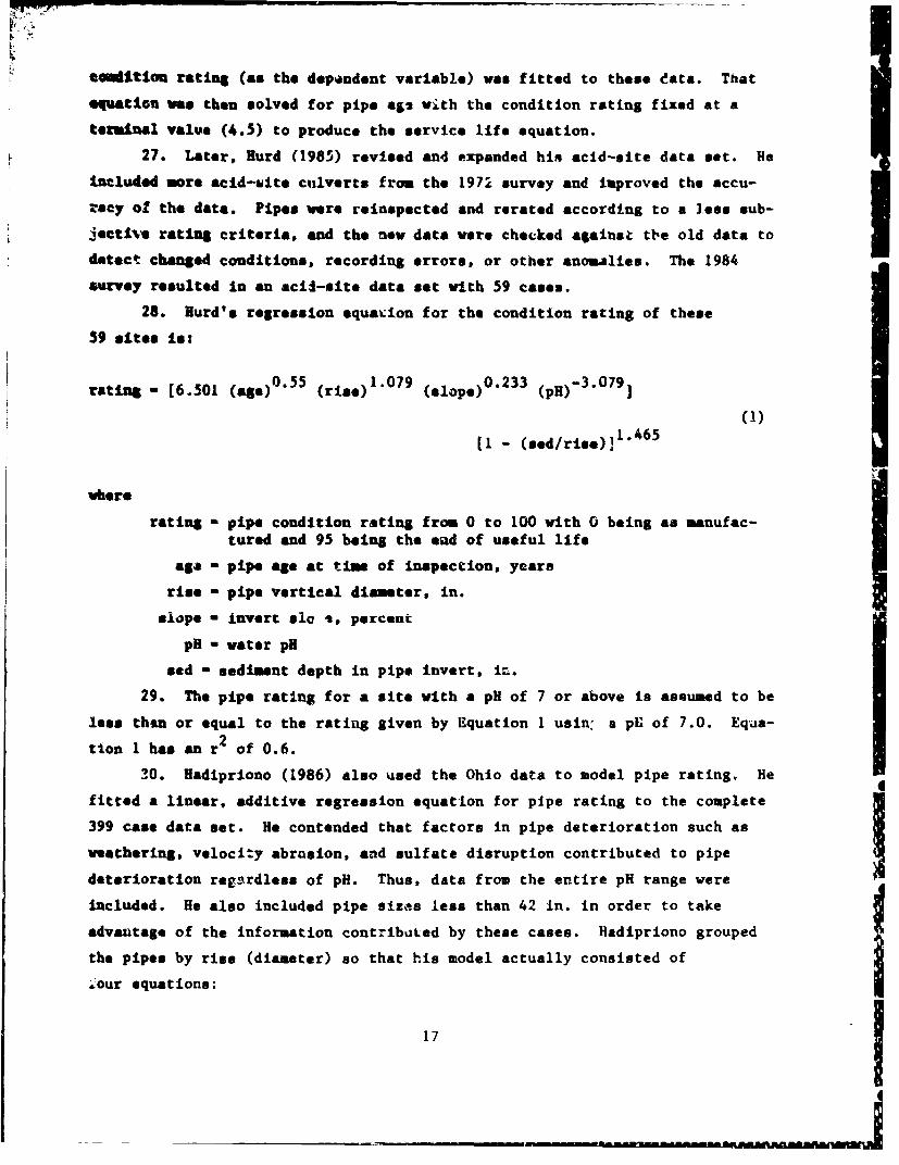
28. Hurd's regression equacion for the condition rating of these
59 slte* is:
rating - [6.501 (ags)0.55 (rise) 1.079 (slope) 0.233 (pH)-3.079]
(1)
(1 - (Sed/rise)]" 4 6 5
where
rating - pipe condition rating from 0 to 100 with 0 being as manufac-tured and 95 being the ead of useful life
aga - pipe age at time of inspection, years
rise - pipe vertical diameter, in.
slope - invert alo %, percent
pH - water pH
sed - sediment depth in pipe invert, in.
29. The pipe rating for a site with a pH of 7 or above is assumed to be
less then or equal to the rating given by E~quation 1 usin, a pU of 7.0. Equa-
tion I has an r 2 of 0.6.
30. Hadipriono (1986) also used the Ohio data to model pipe rating, He
fitted a linear, additive regression equation for pipe rating to the complete
399 case data set. He contended that factors in pipe deterioration such as
weathering, velocity abrasion, and sulfate disruption contributed to pipe
deterioration regnrdless of pH. Thus, data from the entire pH range were
included. He also included pipe sizes less than 42 in. in order to take
advantage of the information contributed by these cases. Hadipriono grouped
the pipes by rise (diameter) so that his model actually consisted of
ý1our equations:
17

rate ".1040 + 0.03082 (age) - 0.073 (flom) - 0.0139 (sod)
(2)
-4.9425 (l• pH) + 0.1 2 76.'slope for rise S 42 in.
rste- 6.2472 -:. 0.03082 (a"t) - 0.073 (flov) - 0.0139 (st3)(3)
- 4.9425 (log pH) + 0.1276/Tope for 42 in. < rise S 48 in.
rate - 6.1946 + 0.03082 (age) - 0.073 ( low) - 0.0139 (&ad)
(4)
- 4.9425 (log pH) + 0 .1 2 7 6 "silope for 48 in. < rise S 60 in.
rate - 6.4770 + 0.03082 (age) - 0.073 (flow) - 0.0139 (sod)
(5)
- 4.9425 (log pH) + 0.12764'lope for rise > 60 In.
where
rate - pipe condL.ion rating from I to 5 vith I being excellent and4.5 being the and of ussf :1 life
flow - water flow velocity ratnmp from I to 5 with I - rapid,2 - moderate, 3 z- slow, 4 - negllgible, and 5 - no flow, and theother varxables are as previous!v def 4 n-d
Equations 7 to 5 can be ctmbined for simplicity (with a new regression
analysis):
rate - 5.7478 + 0.0304 (.ge- - 0.07.52 (,low) - 0.0134 (sed)(6)
- 4.8920 (log ýH) -- 01264v/lop + 0.0085 (rise)
2The r remains about 0.4, uA che relationship of rate to rise becomes a
smooth aonotonic function.A.
31. Equations I ard 6 ard ,thi, Loecpictive r' values cannot be compared
directly because of the differoaces in endition rating scale, flow velocity
rating (0.1 to 3 for the ac3i-site data), and size of the data set. A dir-'t
comparison requires interchanging data sets. Also, sincre the rating scales
ire different, tbe regression analysic must be repeated zo establish rew
coefficienta.
18

31. UVing Hurd's 59 cases Instead of 399, the additive, linear regres-
*I=m equ ion for pip. rating is:
rtir, - 134.1330 + 0.4133 (age) + 4.0657 (val) - 1.3490 (sad)
(7)
- 188.4258 (log pH) + 5.3113/isv-p. + 0.1947 (rise)
vel - water flow velocity rating frow 0.1 to 3, with 0.1 - nil,I - slow, 2 - moderate, and 3 - rapid, and the other variablesare as previously defined
2ith the smaller data set, tht r increases from 0.4 to 0.7 The r 2 for the
uultiplicattve regresion equation drops from 0.6 to 0.3 when the larger data
e*t Is usd . The r2 values are compared below:
Equation
Cases Hadipriono (1966) Hurd (1985)
59 0.7 0.6
399 0.4 0.3
Tbis comparison suggests that the form of Hadipriono's equation (additive,
Line)• r more closely models the phenomenomn, of pipe detarioracion than Hura's
eq'sation (multiplicative, nonlinear) for dither set of data. However, neither
can be described as a "good" model with these low r2 values.
33. Most empirical perfornance or service life relationships are based
on formulas fitted to data from specimens at some terminal or failed condi-
tion. The age used for these equations is the service life. When deteriora-
tion models such as Equations I and 6 are used to prediet service life,
another level of complexity is addsd. The age in these equations is the age
of the specimen at the time of inspection when a rating was assigned. These
equations are used to predict service life by solving for age and setting the
condition rating to same terminal value. There may be very little data with
rating values at or near terminal. Thus, the service life prediction presumes
a relationship foi deterioration with age in addition to relationships between
the other independent variables and the service life. The form of the rela-
tionship between age and rating is critical because it ic used to forecast a
19

e art-e life based on deta from specimens which have not yet failed or per-
femda for their full service life. This relationship may or may not be 3in-
ar. In fact, Hurd contends that it is highly nonlirear. Hurd's equation
(Bmation 1) can act:,. it for nonlinear 4 ty, but Hadipriono's (Equation 6) can-
nt. ouwever, it is important to note that the exponents in multiplicative
equatiome such ao Equatio. I actually serve two purposes. They serve to
Ai-imne the shape of tho relationship, %.ich is nonlinear when the exponent has
a value other tham one. 'Aaey also serve as scaling or %sighting factors to
refl•ct the relative influen:. ot the independent variablet. The exponent cf
am Important independent variable must be larger than the exponent of a lesser
variable to make the correct variable dominate the behavior of the dependent
variable if the relative magnitudes of the independent variables and the forma
or, Ameee of their relationships to the dependont variable are similar. Arege•e"on analysis does not distinguish between adjustments to the exponent
for waebting and adjustments for haproving the shape of the relationship.
?roducing Equation I by regression analysis does not prove that the relation-
skip between age and rating is highly nonlinear. For e:;ample, if age had been
expresee in months or days instead of years, the exponent on age would have
been much maller. Yet, the shape of the true relationuhip of rating with
time mst be the sam.
34. Solving Equation 6 for age and setting rate to a terminal value of
4.3 g1ves the following predicted service life:
servi(.ce life - 41, 5 + 2.47 (flow) + 0.44 (sed)(8)
+ 160.92 (log pH) - 4.16 s/8-lpe - 0.28 (rige)
35. The depth of sediment in the invert (sod) is difficult to ptedict
and is generally undesirable with regard to culvert hydraulics. Therefore, a
sediment depth of zero should be used for design. The flow velocity is also
difficult to predict and is usually highly variable. An average value is rea-
sonable for initial design and economic &nalysis. Usin& the average flow
velocity for the complete data set (3.1604) and zero sediment depth, Equa-
tion 8 reduces to:
20

tIDervi,. life - -33.23 + 160.92 (log pH) - 4. 16 /slope
- 0.28 (rise) (9)
36. By comparison, solving Equation 1 for age at a terminal rating
of 95 (comparable to 4.5) and 0 vediment depth gives
service, life - 123.5 (pH)5 .55 (rise)- 1.94 (slope)-0" 4 2 (10)
37. Equations 9 and 10 give very similar service lives for values of pH
hetween 2 and 4 but differ dramatically at higher values of pH. This depar-
ture results largely from the large value of the exponent (5.55) on pH in
squation 10.
38. loth Squetions 9 and 10 are based on culverts generally not at the
ew4 of their useful lives. However, the times given by Equations 9 and 10
should be consistent with the ages of uulverts rated 4.5 to 5 in the complete
data set and 95 to 100 in the acid-site data set if they accurately predict
service life.
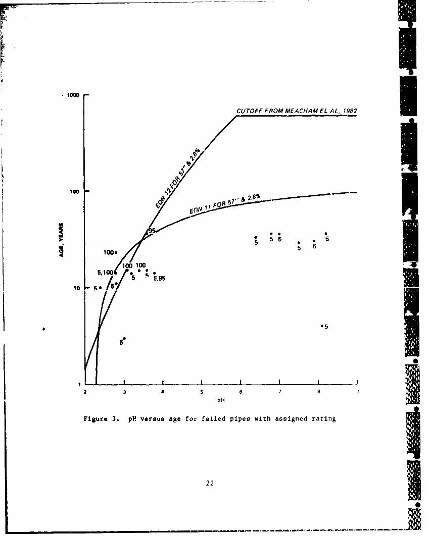
39. There are 20 such data points between the two data sets having
rIees from 30 to 108 in. and slopes from 0.02 to ib parcent. The average rise
le �nt and- the average slop. ta 2.- percent. Figure 3 s0ows Equat.ion, 9
and 10 plotted using these average values for rise and slope along with the
age and pH of culverts rated 4.5 to 5 or 95 to 100.
40. The two culverts rated 5 after only 3 and 4 years appear to be out-
liars. Their poor performance may be the result of a substandard pipe or
other unusual deleterious factor not observed during the inspections. The
remaining 18 points appear to plot in an orderly and logical manner, although
there is considerable scatter as noted earlier.
41. Equations 9 and 10 both fit the data reasonably well in Che pHrange of 2 to 4. However, both appear to overestimate service life for valuesof pH greater than 4. This is caused by the forecasting or prediction of scr-
vice life barod on the ages of culverts still in good condition. A review of
the data prepared reveals that there art many culverts still in good condition
at ages near that of the data shown in Figure 3. This observation suggests
that factors not evaluated are significantly influencing culvert perfcrmance.
21
CUTOFF FROM MEACHAM EL AL, 1982 I11 v
100--
5 e 0
S55 5 50100.
100100
5,9
10- so
*5
3 4 5 6 7 8
pH
Figure 3. pH versus age for failed pipes with assigned rating
22
-r -- -t -- - - - - - - - - - -
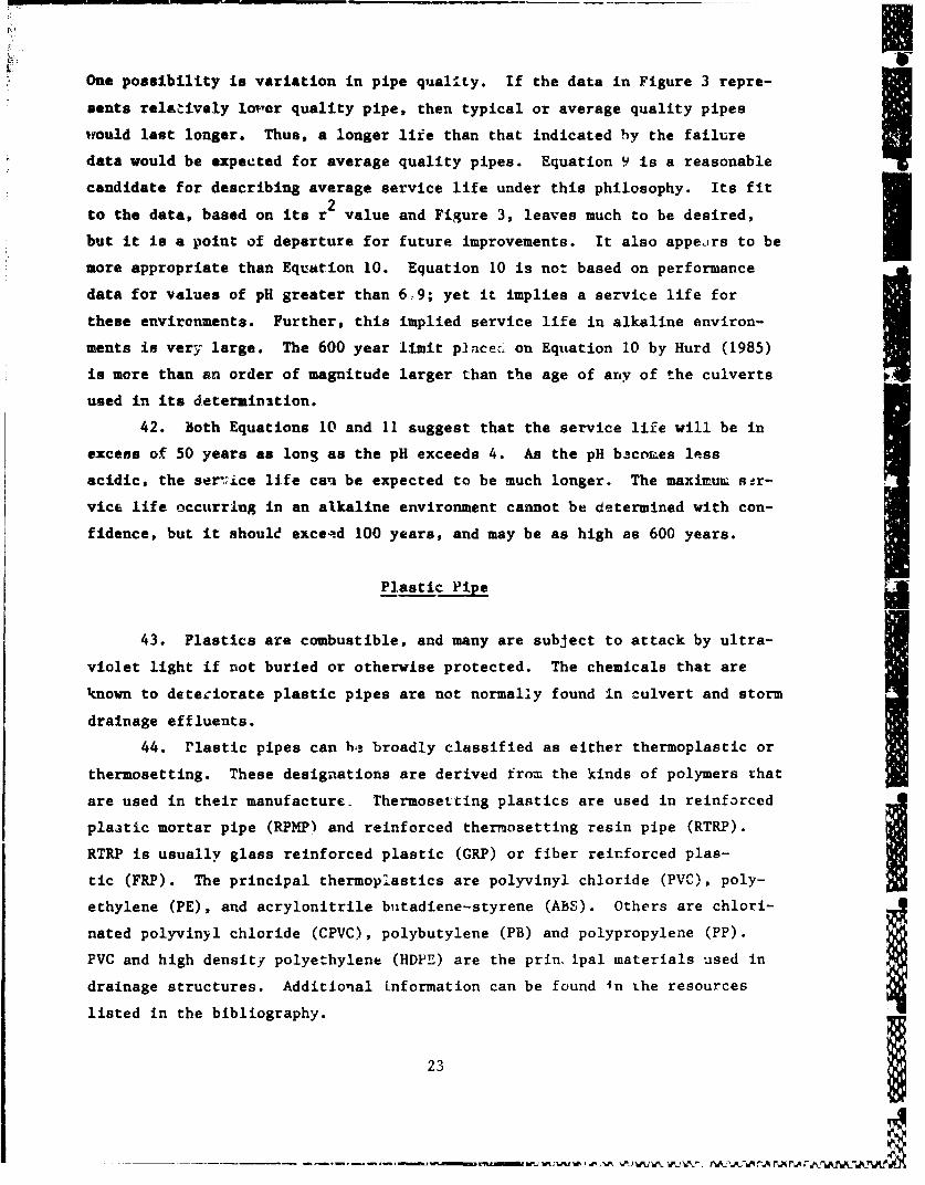
One possibility is variation in pipe quality. If the data in Figure 3 repre-
sents relatively oimer quality pipe, then typical or average quality pipes
would last longer. Thus, a longer life than that indicated by the failure Idata would be expected for average quality pipes. Equation 9 is a reasonable
candidate for describing average service life under this philosophy. Its fit
to the data, based on its r 2 value and Figure 3, leaves much to be desired,but it is a point of departure for future improvements. It also appears to bemore appropriate than Equation 10. Equation 10 is not based on performance
data for values of pH greater than 6.9; yet it implies a service life for
these environments. Further, this implied service life in alkaline environ-
ments is very large. The 600 year limit placec. on Equation 10 by Hurd (1985)
is more than an order of magnitude larger than the age of any of the culverts
used in its determination.
42. Both Equations 10 and 11 suggest that the service life will be in
excess of 50 years as long as the pH exceeds 4. As the pH b3co&es less
acidic, the ser'7ice life can be expected to be much longer. The maximux s!r-
vice life occurring in an alkaline environment cannot be determined with con-
fidence, but it should exceqd 100 years, and may be as high as 600 years.
Plastic Pipe -
43. Plastics are combustible, and many are subject to attack by ultra-
violet light if not buried or otherwise protected. The chemicals that are
known to deteziorate plastic pipes are not normally found in culvert and storm
drainage effluents.
44. rlastic pipes can h,3 broadly classified as either thermoplastic or
thermosetting. These designations are derived from the kinds of polymers that
are used in their manufacture. Thermosetting plastics are used in reinforced
plaatic mortar pipe (RPMP) and reinforced thermosetting resin pipe (RTRP).
RTRP is usually glass reinforced plastic (GRP) or fiber reinforced plas-
tic (FRP). The principal thermoplastics are polyvinyl chloride (PVC), poly-
ethylene (PE), and acrylonitrile biitadiene-styrene (ABS). Others are chlori-
nated polyvinyl chloride (CPVC), polybutylene (PB) and polypropylene (PP).
PVC and high density polyethylene (HDPE) are the prin, ipal materials used in
drainage structures. Additional information can be found i n Lhe resources
listed in the bibliography.
23

•I A45. The mosat significant characteristic of these pipe materials is that
tbey exhibit a visaoelastic response to therw-o .nechanical loading (Chaturvedi
1986). The effective, long-term elastic modulus ts lower than the short-term
modulus due to creep in the loaded material as a function of load and temper-
atur*. This property must be explicitly considered in the structural desigu
to ensure long-term service life. State of the ýrt design procedures
(Schluter 1935, Chambers and McGrath 1906) use P long-term elastic modulus
lese than the initial uodulus to account for loAg term pipe behavior. Var-
ietions on these procedures have been adopted by various standardization
organizations.
46. One of these procedures is the proposed American Association of
State Highway and Transportation Officials (AASHTO) plastic pipe design proce-
dure "Section 18: Soil Thermoplastic Pipe interaction Systems" (Appendix A).
Tha structural design of thermoplastic pipes larger than 6 in. nominal size
should follow this procedure. The structural design of smaller thermoplastic
pipe may alao use this method. The use of effective modulus to define the
ultimate deformation risponse is based on constant and continuous loadiug. In
practice, these two conditions are seldom met throughout the anticipated life
of the pipe, and therefore, the concept of effective, creep modulus has some
inherent safety factor, the magnitude of which depends upon actual conditions.
Hence 1life under Ioada hAe•d on 50-yeAr mnAttliia valu,•i hmhild be cignfi-
cantly greater than 50 yeare and for longer still, under even lighter leeds.
Table 3 ir an example of a cover table based on this procedure. It gives the
maximum and minimum cover requirements for one particular corrugated poly-
ethyleue pipe subject to H20 live loads using 50-year modulus values. Other
pipe constructions, with both corrugated or solid walls, are commercially
available for greater maximum cover heights.
47. Piose made from thermosetting plastics (RTRD, RPMP) should be
designed and inseal.led in accordance with American Society for Testing and
Materials (ASTM) D 3,79-79 (ASTM 1979).
46. For thermopiaqtic pipes (PE, •' ', CPVC, PB, CAB), 6 in. nominal
size and smaller, ASTM D 2321-83 should be followed for design and
installation.
49. Smootih wall, high density polyethylene pipe has demonstrated abra-
sion resistance 3 to 5 times greater than mild steel, documented in
ETL 1110-3-332 (Headquartefs, Department of the Army 1986).
24

F
Tabl* 3
Pipe Covir Requirements for Corrugated Polyethylene
Pipe Subject to H20 Live Loads
Nominal Diaoster Minimum Cover Maximu Cover
in. ft ft
12 1.0 9.6
15 1.0 9.7
18 1.0 10.0
24 1.0 10.3
Notes:a. The suggested maximum heights of cover shown in the table are cal-
culated on the basis of the prcposed AASHTO standard specificationsfor highway bridges, Section 13: Soil-Thermoplastic Pipe Interac-tion Systems using service load design and assuming a soil densityof 120 pcf.
b. Cover depths are measured from the top of the pipe ta the top ofthe ground surface.
c. Regardless of minimum cover requirements, the distance from the topof the pipe to the bottom of the slab of rigid pavements mustexceed the values given in the following tabulation (extracted fromTH 5-820-.3) (Headquarters, Department of the Army 1981) to preventcracking of the slab.
Pipe Size Gear Loadin. Less Than 100 Kips, ft 100 Kips or Greater, ft
6-60 0.5 1.0
66-120 1.0 1.5
Clay Pipe
50. Vitrified clay is perhaps the least corrodible of the common pipe
materials. It is subject to corrosive attack only from hydroflouric acid and
concentrated caustics. It is also very resistant to abrasion (Bortz 1985). UAs a result, vitrified clay is extremely durable in terms of deterioration
from corrosive or abrasive service environmenZs.
51. The National Clay Pipe Institute (1982) his compiled a list
(Table 4) of over 50 clay pipe systems which are still functioning after up to
170 years and which are used to support a 150-year service life. However,
'5

ITable 4
Old Clay Pipe Installations
Still in Service*
Date Date- City Installed City Installed
1. Washington, DC. 1815 27. Baltimore, Md. 1871,2. Philadelphia, Pa. 1829 28. Portland, Maine 1875
3. Boston, Mass. 1829 29. San Francisco, Calif. 18764. Sydney, N.S. Wales 1832 30. Jacksonville, Fla. 1876
5. Manchester, England 1845 31. Albany, Ga. 18766. Liverpool, England 1846 32. St. JosEph, Mo. 18767. London, England 184? 33. Davenport, low% 18778. Clinton, Iova 1850 34. Kansas City, Mo. 18779. Uinburgh, Scotland 1850 35. New Bedford, Mass. 1877
10. Rigby, England 1851 36. Bucyrus, Ohio 87711. Croydon, England 1851 37. Omaha, Nebr. 187812. Darlington, Zngland 1252 38. Camden, N.J. 187913. Chicago, Ill. 1855 39. Memphis, Te-in. 187914. Cleveland, Ohio 1861 40. Parkersburg, W. Va. 187915. Nov York, N.Y. 1866 41. Providence, R.I. 187916. Erie. Pa. 1868 42. Nashville. Tenn. 1R7917. Grand Rapids Mich. 1869 43. Rome, Ga. 188018. St. Louis, Mo. 1869 44. Rockfori, Ill. 188019. Hartford, Conn. 1870 45. Terre Haute, Ind. 188020. Indianapolis, Ind. 1872 46. Sioux City, Iowa 188021. Los Angeles, Calif. 1873 47. Red Wing, Minn. 188022. New Haven, Conn. 1873 48. Reno, Nev. 188023. St. Paul, Minn. 187$ 49. Fazgo, N. Dak. 188024. Portland, Oreg. 1873 50. Dallas, Tex. 188025. Raleigh, N.C. 1873 51. Denver, Colo. 188026. Lawrence, Kans. 1874
* From National Clay Pipe Inscituti 1982.
26

Fet of the referenced systems are just over 100 years old. Thus, and
partlcularly in light of the uucertalaty in long-term (over 100 years) land
w, It to appropriate to limit the design service life of vitrified clay pipe
to 100 years.
Sumary
52. A 50-yeax service life can be used for most types of drainage
structures. Limits on pH and resistivity can be u~ed to ensure that metal
pipes rU'ill perform satisfactorily for this period. Also, the California
method, along with the added life afforded by protective coatit,,s, can be used
to estimate the service life of a corrugated steel pipe or develop a combina-
tion it 4ipa and coating to last 50 years in a particular environment.
53. Limits on pH and sulfides can be used to ensure the satisfactory
performance of conerite pipes. As the pH increases from 4 to 9, reinforced
coucrete pipe life increases from about 50 years to over IGO years, depending
on pipe diameter and slope. As with meta! pipe, there is considerable vari-
ability in actual service life, and the available data cannot be used to con-
fi•ently estimate service life.
54. Plastic pipe should provide much more thtn 50 years of service a*
lons as it is not exposed to ultraviolet light and the structural design is
based on the, long term creep behavior of the plastic The proposed AASHTO
design procedure is one such procedure and may be used pending its adoption.
55. Clay pipe is perhaps the most inert of the common pipe materials in
terms of corrosion, and it is very resistant to abrasion. A 100-year service
life may Le assumed for most clay pipe installations.
27
_A A m.AAiA' V.RAA PWA16RA

PART III: LIFE CUCLE COST METHODOLOGY
General
56. The first step in the analysis of design alternatives is to developa preliminary list of all possible alternatives. This list is then reduced to
a group of feasible alternatives by applyin• the constraints of the particularproject such as availability of materials or equipment, site conditions such
as abrualve bed load, or requirements to accomodate large flows or livestock.
The minimum functional requirements must be net. The final design is chosen
from this greup based on LCC.
57. The LCC is the total, overall estimated cost for a particular
design alt&rnative. Direct and indirect initial costs plus periodic or
cc itinuing tosts for operation and maintenance are included. The methods
describel in TM 5-802-1 (Headquarters, Department of the Army 1986) and
mentioned belovi account for the time value of money and reflect the concepts
and procedures used in many economics texts (Theusen, Fabrycky, and Theusen
1971).
58. Costs incurred over time may be expressed in terms of either con-
stant dollars or current Aollars. Constant dollars are costs (or savings)
stated at price levels in effect at some given time, usually the particular
tce that the analysis is conductea. Current dollars are costs or savings
stated at ptice levels in effect whenever the costs or savings are incurred.
Comparison of drainage structure alternetives should be based on constant
dollars for all costs including present and future costs and for salvage or
retention/resinual values.
59. The ',CC in expressed either in terms of present wcrth (PW) or
equivalent uniform. annual tost (EUAC). PW is the primary measure of LCC. It
is the amount of money required now to fund the project for the entire analy-
sis period. The xUAC is the amount of money required for each year of the
analysis perind tc fund all project costs.
60. The same analysis period must be used to compare alternatives using
PW's. PW's can be converted to EUAC using a uniform series capital recovery
factor. In this case, PW and EUAC are just two ways of expressing the same
costs. EUAC can also be calculated from the individual cocts for each
alternative.
28

Analysis Period
61. Economic studies consider projects which have a service life, an
economic life, and an analysis period. The service life is the tot.1 useful
life of the project or time to replacement or rehabilitation. The economic
life is the time during which a project is economically profitable or providesthe required service at a lower cost than another facility. For drainagestructures, the economic life is usually the same as the service life. The
analysis period is the comparison period over which costs are counted in
determining the PN or XUAC of an alternative.
62. Guidance for selecting the analysis period is given in APi 11-28
(Headquarters, Department of the Army 1975) as shown below:
Vie alternative with the longest economic life maydetermine the end of tlVe comparison period. However,the decision maker or analyst may shorten this periodconusistent wi.h the objectives and assumptions of theanalysis. Whether the longest or shortest life isused as a basis, adjustment for unequal life israquired. If the shortest life is used the residualvalues of the alternatives with longer lives must oerecognized in the cost computation for those alterna-tives. Sbould the longest life be used to establishthe tine period of the analysis, the cost of extendingthe benefit producing years of those alternatives witha shorter life must be recognized. Care should beexercised to ensure that the costs fir each alter-native for the entirc period of comparison are pro-cented to the decision maker. Another alternativewould be the use of uniform annual cost methods as ameans of comparison [5, p. 2-5].
63. TM 5-802-1 further limits the analysis period to the economic life
or 25 years, whichever is less. The 25-year limit is based on the projected
economic life of the complete facility encompassing the drainage structure,
which is usually around 25 years for general planning purposes. However,
infrastructure such as drainage facilities may realistically be expected to
provide economical service, in its original mission, well beyond 25 years. A
review of the service lives used by various state and federal Government
agencies and industry (Renfro and Pyskadlo 1980, Sunmerson 1984) reveeal that
most agencies expect culverts to provide service longer than 25 years with a
50-year life used most frequently. This period strikes a balance between the
29
ýAM P MM KLA RA FLA~. %.Aa P.A, -%A NX*J Ii

latagible and/or indire:t costs associatad with replacement or rehabilita-
tioa, sad the unpredictability of long-term land use. Based on the service
life guidelines for metal, concrete, plastic, and clay pipes (Part II), a
5O-ymar ano.ysis period is justifiable and should be used, subject to the
approval as described in TM 5-802-1 (Headquarters, Department of the Army
1986) of HQUSACE (CEEC-EG) for Army projects an.. HQUSAF (LEEEC) for Air Force
projects.
Costs
64. The initial and recurring costs considered in an economic analysis
are sonetimes categorized as agency tosts, user costs, and ncnuser costs (Hass
and Hudcon 1978). Agency costs include initial capital costs of construction,
future capital costs of rehabilitation or replacement, maintenance and/or
operational rosts during the analysis period, salvage or retention/residual
value (a negative cost) at the end of the analysis period, and engineering and
,dMlnistrative costs. User costs are usually included in the cost of the
f .eility being drained by the drainage structure. Those costs include travel
time, vehicle operating costs, accident costs, and inconvenience (as when a
detour in requir ,). Nonuser costs result from the impact of the facility or
chose not sctually using the f&cility such as the cost of flood damage occur-
ring dovnstre¶. )f the drainage structure.
65. EC. ic analyses frequently include only the initial and future
capital coste, .nten~nce and operation costs, and salvage or retention/
residual value. For drainage structures, the other costs are likely to be
similar for all si trnatives. Thus, little error is introduced by omitting
them from the comrttations. One exception is the user cost associated with
replacement of a bi.•ucture during the analysis period. Replacement c• struc-
tures under high-volume ftcilities may cause expensive delays and detour
costs, as well as reconstruction costs well in excess of the marginal cost
associsted with the initial instal.lltion of the structure.
66. Initial capital costs for drainage structures can generally be
estimated from local data, usually obtainable from local vendors. Future
capital costs except as noted, can be estimated from current costs, adjusted
an necessary for the time expected before future construction. As a supple-
ment, or if local data are not available, costs can be estimated using the
301

procedures, rates, and adjustment factors given in AR 415-17 (Headquarters,
Department of the Army 1980), Enrineering News Record's Building and
Construction Cost Index Histories (Engineering News Record 1987), the Highway
Kaintenince and Operation Coat Trend Index (Federal Highway Administration
1987), and the Price Trends for Federal-Aid Highway Construction (Federal
Highway Administration 1987). A description of these resources and their use
are included in Kohn, Epps, and Rosser (1987).
67. Maintenance and operations costs are best determined from local
experience with similar projects. Maintenance and operations costs are highly
dependent upon both local conditions and the particular maintaining agency.
68. The salvage or retention/residual value of a drainage structure is
its residual value at the end of the analysis period. If the end of the anal-
ysis period coincides with the end of the service life of the alternative,
then the salvage value of that alternative can probably be taken as zero.
When the service life is expected to exceed the length of the analysis period,
the retention/recidual value must be included, generally as a future income or
negative cost.
Discount Rate
discount rate is the amount that the value of money in the future is reduced
or discounted to reflect its present value. It can also be viewed as the min-
imum real or net :ate of return, after inflation, to be achieved by public
sector investments. Congress has stipulated that diverting investment capital
trom the private sector (by taxation) can only be justified when that capital
is used on public-sector projects having a rcal rate of return at least as
high as that achievable in the private sector. Through OMB Circular A-94
(Office of Management and Budget 1972), this rate has been set at 10 percent.
31
(Ofc of Maagmetan Bdet192) hi rr ha bee se pret
r w Computing Present Worth
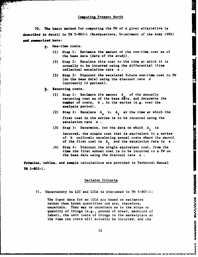
70. The basic method for computing the PW of a given alternative is
deocrtIbed in detail in TX 5-802-1 (Headquarters, Department of the Army 1986)
sad smmarised here:
a. One-time costs.
(1) Step 1: Estimate the amount of the one-time cost as ofthe base date (date of the study).
(2) Step 2: Escalate this cost to the tine at which it isactually tco be incurred using the differential (frominflation) escalation rate a I
(3) Step 3: Discount the escalated future one-time cost to PW(on the base date) using the discount rate d(currently 10 percent).
b. Recurring costs.
(1) Step 1: Estimate the amount A of the annuallyrecurring cost as of the base dite, and determine thenumber of costs, k , in the *eries (e.g. over theanalysis period).
(2) Step 2: Escalate A° tL At at the time at which the
first cost in the series is to be Incurred using theescalation rate .
(3) Step 3: Determine, ior the date on which A1 is
incurred, the single cost that is equivalent to a seriesof k uniformly escalating annual costs where the amauntof the fi:st cost is Ai and the escalation rate is e
(4) Step 4: Discount the single equivalent cost, from thetime the first annual cost is to be incurred to a PW onthe base datr using the discount rate d .
Formulas, tables, and sample calculations are provided in Technical ManualTM 5-W02-1.
Decision Criteria
71. Uncertainty in LCC and LCCA is discussed in TM 5-802-1:
The input data for an LCCA are based on estlmatesrather than known quantities And are, therefore,uncertain. They may be uncertain an to the scope orquantity of things (e.g., pounds of steel, manhcurs oflabor), the unit costs of things in the marketplace atthe time the costs will actually be incurred, and the
32
UinUMWWAMn" MA~fLM NMftA AB rU

r; timing of cost (e.g., when a floor covering willrequire replacement). The effects o7 uncertainties o.ithe results of an LCCA can be quite signif 4.cant. Theymay distort the results of the analysis or dominatethem so that one alternative may appear to be lowestIn not LCC under one set of reasonable assumptions and
highest in net LCC uuder another equally reasonableset of assumptions. For these reasons, the need foruncertainty assessment will be considered as part ofevery LCCA.
a. Specific tequirements. The decision as to whether or not anuncertainty assessment is raquired for any particular LCCA willdepend on a number of factors and so must be made on a case-by-case basis. Among these factors are whether or not the LCCAresults appear to be clear-cut, whether or not the relativeeconomic rankings of the (apparently) top-ranked alternativeand its nearest competitors could be affected by the results ofthe aseesee~nt, whether or not the LCCA results have to beapproved by higher Command authority prior to impleneitation,and whether or not the LCCA results are likely to be controver.-sial (as are deviations from criteria, changes from commonpractice, rejections of special user preferences, and signifi-cantly greater Initial cost requirements that result in onlymarginal LCC savings). In general, an uncertainty assessmentneed not be performed if either of the following conditionsapplies.
(1) The relative economic rankings of the (apparently) top-ranked alternative and its nearest competitors cannot beaffctad by of theass
(2) The LCCA results appear to be clear-cut, either clearlyconclusive or clearly inconclusive, in advance.
In addition, even if the LCCA results appear not to be clear-cut (i.e., not clearly conclusive and not clearly inconclusive)(especially the latt-r), an uncertainty assessment is not con-sidered necessary provided the design decision is a routine one(i.e., one which may be implemented locally without the needfor higher-authority approval) and is one that isunlikely to be controversial when implemented.
b. Approaches. Of the two leading approaches to uncertaintyassessment, the probabilistic approach is more direct and thegenerally applicable for MCP designs, and it should be usedwhenever appropriate. Sivrce the rigorous probabilisticapproach is too complex for routine use, reasonable approxima-tions to that approach are preferred for MCP design applica-tions. The other leading approach to uncertainty assessment,the sensitivity approach, may be used in any situation in whichthe approach is valid; however, in all cases in which the prob-abilistic approach and the sensitivity approach are both valid,the probabilistic approach is preferred. In those situationswhere neither the probabilistic approach nor '.he sensitivity
33

approach can be considered to be valid, uncertainty assessmentmay be accomplished by means of any common-sanse heuristicapproach-preferably one based on either the probabilistic orthe sensitivity approach, or on some combination ofthe two (pars 2-2, b. (9)).
72. In the case of a tie between any of the alternatives, tha relative
ranug can be datermined using the following guidance, also from TM 5-802-1:
If any alternatives ive determined to have comparablenet LCC's either because their calculated net LCC's
are essentially equal or because the uncertaintiesessociated with the analysis are found to be suffi-ciently large to render apparent net LCC differencesinconclusive, then their relative rankings will bebased on a combination of energy conservation andinitial procurement cost considerations, as outlinedbelow. For those situations in which the LCCA resultsappear not to be clear cut, the criteria for judgingwhether apparent net LCC differences are conclusive orinconclusive and, hence, whether the LCCA results areconclusive or inconclusive are as follows:
a. A positive net LCC difference between two alternatives is con-clusive If it can be shown that the probability of thaL differ-ence exceeding zero is no less than 0.60.
b. A positive net LC difference between two alternatives isinconclusive if it can be shown that the probability of thatdifference exceeding zero is no greater than 0.55. Finally, inthe absence of net LCC determinations either because an LCCAhas not been conducted or because one has been conducted butnot in strict -ccordance with the criteria contained herein(e.g.. it was not based on the best information available atthe time), design alternatives will be given economic rankIngsbased solely on initial procurement cost considerations.
c. Tie breaking. If two design alternatives have comparable netLCCis, and it can be demonstrated with a high dehree of confi-dence that one of these alternatives satisfies any of the fol-lowing conditions, then that alternative will be assigned thehigher relative ranking:
(M) It will be less expensive in terms of initial procurementcosts and will consume rn more fuel/enerhy per year.
(2) It will consume less fuel/energy per year and will be nI
more expensive in terms of initial p' -urement costs.
(3) It will consume at least 15 percent less fuel/energy peryear and will not be more than 15 percent more expensivein terms of initial procurement costs.
34
- - - - - - - - - - - - - -

(4) It will be at least 15 percent less expensive in terms ofinitial procurement costs and will consume no more than15 percent more fuel/energy per year.
When the two alternatives are of different fuel/energy types,quantities of fuel or energy consumed annually wMll be deter-mined in Btu equivalerts, measured at the source, in accordancewith standard practice within the Department of Defense formeasuring energy savings. If none of these conditions are sat-isfied, then the two alternatives will be assignad the sameranking. In those cases vhwn two or more of the alternativesconsidered for any desiga feature are tied for the highestranking, seletion will be based on the designer's judgement asto which of the alternatives tied for the top ranking repre-sents the best overall choice in terms of initial cost, energyconsumption, and LCC for the application at hand(para 2-2. c.).
Example
73. Suppose a drainage structure is being selected for construction
2 years after the analysis base data (date of study). The soil/water pH is
6,0, the ainuimm soil/water resistivity is 6,000 ohm-ca, and a nonabrasive
flaw of 6 ft/sec is expected. The facility being drained is a low volume road
with shallow pipe cover, so replacement costs are similar to initial con-
struction costs, and no significant user costs are expected from delays or
A-stnisre- The materlAl, to be considered are reinforced concrete (RCP), plain
galvanized (CSP), asphalt coated and paved corrugated steel pipe (ACPCSP),
plain aluminum (AL), and polyethylene (PE) pipe. All of these alternatives
are structurally adequate for the design load. A 24-in. diam smooth vall pipe
will carry the design flow at the design slope of 1 percent. A 27-in. diam
pipe will be required for the corrugated alternatives because of their higher
n value. The differential escalatlon rate is projected to be zero for
installation costs and for the concrete, aluminum, and plain galvanized mate-
rials. A rate of 3 percent will be assumed for the total cost the asphalt
coated and paved corrugated steel and polyethylene pipes to account for
expected increases in the cost of petroleum and natural gas, respectively.
Assume that an exception will be granted to allow a 50-year analysis period,
that maintenance costs over the analysis period are equal for all alterna-
tives, that the facility is to be abandoned at the end of the analysis period,
and that pipe still serviceable at the end of the analysis period will not be
35
-- - AAfl& U R&AML&RAN1L AP..' NAAJM AAREXL~ N A PAJ kP'n

recovered for reuse or resale (no salvage value). Uncettainty analysis will
bo omitted for simplicity. The costs stated herein are hypothetical costs.
They do not apply to any particular project, do not reflect current market
prices, and are not to be used for an actual LCCA.
74. From Equation 9, the expected service life of reinforced concrete
pipe is about 80 years. It should therefore last through the entire analysis
period. The current cost is $12.50/ft, delivered, plus $10.00/ft for instal-lation. Since e0= for both materials anO. installation, the one-time cost to
be incurred in 2 years is simply 12.50 + 10.00 - $22.50/ft, in terr., of
today's dollars. The IW is $18.59/ft.
75. Since the pH is near the envirenmental limits specified in para-
graph 7 for plain galvanized pipe, Equation 2 should be used to estimate the
service life of that alternative. For a pH of 6.0 and a minimum resistivity
of 6,000 ohm-ca, a 16 gage, plain galvanized CSP has an expected life of about
25 years. This alternative will require a replacement at the midpoint of the
analysis period. The current cost of 27 in. plain galvanized pipe is
$10.65/ft, delivered, including bands, plus $8.50/ft for installation, for
both initial construction and replacement. Since e-0 ior both materials and
installation, the cost to be incurred in 2 years and again in 27 years is
10.65 + 8.50 - $19.15/ft. The PW of the initial installation is 19.15
(1/1.1) - $15.82/ft. The PW of the replacement is $19.15 (1/1.1)27
- $1.46/ft. The total PW for this alternative is thus 15.82 4 1.46
- $17.28/ft. All these are expressed in terms of today's dollars.
76. Asphalt coating and paving can be used to extend the life of plain
galvanized pipe. Assume that this coating will add 25 years to the life of
the pipe. The service life of an ACPCSP at this site will be 25 + 25
- 50 years, and no replacement is anticipated during the analysis period. The
current cost for ACPCSP is $13.90/ft, including bands. Assuming a 3 percent
annual differential escalation rate due to the cost of the asphalt, the pipe2will cost 13.90 x (1.03) . $14.75/ft at the time of installation. Installa-
tion is currently $9.50/fc. Assuming e-0 for installation, this cost will
remain at $9.50/ft. The total cost of this alternative will thus be 14.75 +
29.50 - $24.25/ft. The PW is 24.25 (1/1.1) . $20.04/ft.
77. The proposed AASHTO design procedure (Appendix A) is structured to
provide a 50-year service life. One 24-in. smooth-flow PE pipe meeting the
requirements of this procedure costs $16.50/ft. An escalation of 3 percent
36

for 2 years yields a cost at time of installation of 16.50 x (1.03)2
- $17.50/ft. Inctallation is and will be (e-0) $8.00/ft. At the time of
2 l .) Iinstallation, the total cost will be 17.50 + 8.00 ,, $25.50/ft. The PW is
25.50 x (121.1) $21.08/ft.
78. This site is within the environmental limits for aluminum pipe;
therefore, a life in excess of the required 50 years can be expected. The
current cost for aluminum pipe is $11.90/ft, including bands. Installation is$8.00/ft. Since the differential escalation is zero for both material and
installatLion, the future cost will be 11.90 + 8.00 - $19.90. The P1I is
19.90 x (1/1.1)2 16.44/ft.
79. The life cycle cost of these altcrnatives is summarized below:
24 in. 27 in. CSP 24 in. 24 in. 27 in.Cost RCP 1st 2nd Total ACPCSP PE AL
Current Material 12.50 10.65 10.65 13.90 16.50 11.90Installat.o.. (e-0) 10.00 8.50 8.50 9.50 8.00 8.00Escalated Material 12.50 10.65 10.65 14.75 17.50 11.90PY Material 10.33 8.80 0.81 9.61 12.19 14.47 9.83PW Installation 8.26 7.02 0.65 7.67 7.85 6.61 6.61Total PW 18.59 17.28 20.04 21.08 16.44Choice 3 2 4 5 1
In this example, plain corrugated aluminum pipe (AL) would be chosen for its
lowest LC.C. if two or three alternatives are to be selected as bid optiona,
then AL and CSP or AL, CSP, and RCP would be considered.
Siummary
8(. The LCC of drainage structures is determined according to the
criteria in TM 5-802-1. Because of the nature of drainage structures, an
analysis period greater than 25 years may be justified. The alternatives are
order ranked by LCC, and the alternative with the lowest LCC is selected.
Uncertainty in the true cuscs and tie-breaking crite ' are addressed in
TM 5-802-1.
37
______-~1--U-"--,..''%PinAKajIý1 " W.AJUIJM

PART IV: CONCLUSIONS
81. The LCC of a drainage structure design alternative is the estimated
total cost of that design. Except for determining a service life for the
various type. (materials) of drainage structures, the procedures for LCCA
are well eat: bulshed. The guidelines presented in Part II of this report canbe used to estimate the service life of a particular design or to ensure a50-year service life. Thus, the procedures for econoaic analysis described in
TM 5-802-1 can be used to determine LCC. While the LCC is only one of the
decision factors used to select the preferred design alternative from among
the feasible alternatives, it is generally the most important. The importance
of the other decision factors are established by the minimum functional
requirements of the project. The alternatives can then be order ranked by
LCC, end the best design can be rationally and confidently selected.
I38 1

REFERENCES
Life Cycle Cost
Engineering News Record. 1987. "Building Cost 'ndex History and ConstructionCost Index History," published monthly by McGraw-Hill, Inc., New York.
Federel Highway Administration. 1987. "Highway Maintennnce and OperationCost Index," published quarterly, Washington, DC.
•1987. "•Price Trends for Federal-Aid Highway Construction,"'
published quarterly, Washington, DC.
Bass, K. and Hudson, W. R. 1978. "Pavement Management Systems," McGraw-Hill,Inc., Now York.Headquarters, Department of the Army. 1980. "Construction-Cost Estimating
for Military Programming," AR 415-17, Washington, DC.
_________", 1975. "Economic Analysis and Proper Evaluation for ResourceManagement," AR 11-28 and Department of the Air Force AFR 178-1, Washington,DC.
_ 1986. "Economic Studies for Military Construction Design
ApplicationE," TM 5-802-1, Washington, DC.
Kohn, S. D., Epps, J. A., and Rosser, T. B. 1987. "Analysis Procedures forPavement Life Cycle Cost," US Army Engineer Waterways Experiment Station,Technical Report in preparation, Vicksburg, Miss.
Office of Management and Budget, Executive Office of the President, CircularNo. A-94, March 27, 1972, Washington, DC.
Renfro, W. W., and Pyakadlo, R. M. 1980. "National Survey of State Culvert_lee n_4 Pnllrien." Now York Department of Transportation Special Report 68,Albany, New York.
Summerseon, T. J. 1984. "Corrosion Resistance of Aluminum Drainage Products:The First 25 Years," Symposium on Durability of Culverts and Storm Drains,Transportation Research Record 1001, Transportation Research Board, Washing-ton, DC.
Thuesen, H. G., Fabrycky, W. J., and Thuesen, G. J. 1971. "Engineering Econ-
cay," 4th Ed. Prentice-Hall, Inc., Englewood Cliffs, N. J.
Metal Pipe
Amrican Iron and Steel Institute. 1983. "Handbook of Steel Drainage andHighway Construction Products,' 3rd Ed., Washington, DC.
California Department of Transportation. 1972. "California Method for Esti-mating Service Life of Metal Culverts," Teat Method No. Calif. 643-C, Sacra-mento, Calif.
Federal Highway Administration. 1979. "Corrugated Metal Pipe DurabilityGuidelines," Technical Advisory T5040.12, Washington, DC.
Morris, G. E., and Bednar, L. 1985. "Comprehensive Evaluation of AluminizedSteel Type 2 Pip* Field Performance," Transportation Pesearch Record 1001,Transportation Research Board, Washington, DC.
39

Teak Force 22. 1988. "AASHTO-AGC-ARTBA Survey of Culvert Specifications" in
Temples W. H. and Cumbaa, S. L. 1986. "Evaluation of Metal Drainage PipeDurability Analysis After Ten Years." Transportation Research Board, 65thAnnual Meeting, Washington, DC.
Transportation Research Board. 1978. "Durability of Drainage Pipe," NCHRPSynthesis of Highway Practice No. 50, Washington, DC.
1984. "Symposium on Durability of Culverts and Storm Drains,"Transportation Research Record 1001, Washington, DC.Tupac, G. J. 1987. "Corrosion Survey on Corrugated Steel Culvert Pipe" to
State of California Department of Transportation, for USS-POSCO, USX,Pittsburgh, Pa.
Zaccola, J. C., Townsend, H. E., Borzillo, A. R., and Horton, J. B. 1978."Atuospheric Corrosion Behavior of Aluminum-Zinc Alloy-Coated Steel," Atmo-spheric Factors Affecting the Corrosion of Engineering Metals, ASTM STP 64b,S. K. Coburn, Ed., American Society for Testinr and Materials, Philadelphia,
Concrete Pipe
American Concrete Pipe Association. 1981. "Ciicrcte Pipe Handbook," Vienna,Va.
___ _ 1984. "Design Manual for Silfide Corrosion Prediction and Con-trol, Vienna, Va.Eadipriono, F. C. 1986. "Durability Study of Concrete Pipe Culverts: Ser-vice Life Assessment," The Ohio State University, Columbus, Ohio.
budsz, J. 0. 1984. "Field Performance of Concrete and Corrugated Steel PipeCulverts and Bituminous Protection of Corrugated Steel Pipe Culverts," Trans-portation Research aecord 1001, Transportation Research Beard, Washington, DC.
1985. "Field Performance of Concrete Pipe Culverts at Acid Flow1ites in Ohio," Transportation Research Record 1008, Transportation ResearchBoard, Washington, DC.
Keacham, D. G., Hurd, J. 0., and Shisler, W. W. 1982. "Ohio Culvert Durabil-ity Study," Ohio Department of Transportation, Columbus, Ohio.
Ring, G. W. 1984. "Culvert Durability: Where Are We?" TransportationResearch Record 1001, Transportation Research Board, Washington, DC.
US Department of Labor, Bureau of Reclamation. 1975. "Concrete Manual," 8thEd., US Goverment Printing Office, Washington, DC.
Plastic Pipe
American Society for Testing and Materials. 1979. "Standard Practice forUnderground Installation of Flexible Reinforced Thermosetting Resin Pipe andReinforced Plastic Mortar Pipe," ASTM D 3839-79, Philadelphia, Pa.
• 1983. "Standard Practice for Underground Installation of Flexi-
ble Thermoplastic Sewer Pipe," ASTM D 2321-83, Philadelphia, Pa.
Chaturvedi, S. K. 1986. "Plastic Fipc in Drainaj Structures," The OhioState University, Colum )us, Ohio.
40

VI
.Mmbers, R. E., and McGr'th, T. J. 1981. "Structural Design of Buried Plas-tic Pipe," Proceeding of the International Conference on Underground PlasticP&a.L American Society of Civil Engineers, New York.
Veadqa•rters. Department of the Army, 1981. "Drainage sad Erosion-Controlk Structures for Airfields and Heliports," TM 5-820-3, Washington, DC.
_ _ . 1986. "Engineering and Design - Field Applications of Poly-ehylene Pipe in Dredging," ETL 1110-3-332, Washington, DC.
obliater, J. C. 1985. "Large Diameter Plastic Pipe," Proceeding of theInternational Conference on Advances in Underground Pipeline Engit -ering,Asiarican Society of Civil Engineers, New York.
CJa? Pipe
Bortz, S. A. 1985. "Durability of Clay Pipe," Proceeding of the Interna-tleual Conference on Advances in Underground Pipeline Engineering, AmericanSociety of Civil Engineers, New York.
lational Clay Pipe Inst 4 tute. 1982. "Clay Pipe Engineering Manual,"Cryetal Lake, Ill.
41

BIBLIOGRAPHY
Aumianum Association, The. 1983. "Aluminum Drainage Products Manual," TheAluminum Association, Washington, DC.
hdrAr, L. 1980. "The Durability of Galvanired Highway Culverts," Seminar onPerformance of Galvanized Products, American Hot Dip Galvanizers Association,Chicago, I11.
_ 1985. "Ohio DOT Culvert Durability Report," Letter Report forAMco Construction Products Division, ARMCO Research and Technology, Middle-town, Ohio.
. 1985. "Ohio DOT Report on Culvert Pipe Durability," Lettereport for ARMCO Construction Products Division, ARNCO Research and
Technology, Middletown, Ohio.
1985. "N.Y. DOT Culvert Durability Study," Letter Report for0OConstruction Products Division, ARMCO Research and Technology, Middle-
toaw, Ohio.
Brown, R. 1964. "Pipe Evaluation Study - 1964," Southern Association ofState Highway Officials, Annual Meeting, New Orleans, La.
Cleary, H. J. 1985. "The Microstructure and Corrosion Resistance ofAblaimm-Zinc Coatings on Sheet Steel," Microstructural Science Vol. 12,New York.
Headquarters, Department of the Army. 1969. "Engineering and Design -
Conduits, Culverts, and Pipes," Engineer Manual 1110-2-2902, Washington, DC.
aiirach, C. 1985. ,-y-OrT Proposed Recommendations," NCSPA Memorandum, Wash-ington, DC.
Wnland Steel. 1983. "Blac-Klad 10.10 Performance Report," Chicago, Ill.
Jacobs, K. 1976. "Alumir'jm Culvert Corrosion," Materials and Research Divi-sloe Technical Paper 76-5, Maine Department of Transportation, Bangor, Maine.
rfoepf, A. H., and Ryan, P. H. 1986. "Abrasion Resistance of Aluminum CulvertlUsed on Long-Tsrn Field Performance," Transportation Research Beard, 65thAnmual Meeting, Session 195, Washington, DC.
Lmsomn, H. R. 1980. "Data on Aluminized Steel Type 2 CorrugRted Steel Pipe -CALTRAIS," Memorandum, ARMCO Researcha and Technology, Middletown, Ohio.
New Tor% Department of Transportation. 1966. "Dursbility of Corrugated MetalCulverts," Research R9port 66-5, New York.
Peterson, D. E. 1973. "Evaluation of Aluminum Alloy Pipe for Use in Utah'sHighways," Utah State Department of Highways Salt Lake, Utah.
Su rson, T. J. 1982. "1981 Survey of Type II Aluminized Steel kivited Cul-vert Test Sites," Kaiser Aluminum and Chemical Corporation - Center for Tech-nology, Report ZCFT-82-35-TJS, Pleasanton, Calif.
Swenson, H. N., and Donnelly, D. E. 1977. "Performance of Culvert Materialsin Various Colorado Environments," Colorado Department of High'ys Reportgo. CDOH-P&R-R-77-7, Denver, Co.
42

"WVebington State Highway Commission. 1965. "Culvert Performance Evaluation,"Olymia, Wash.
fteeling Corrug.ating Company. 1983. "Wheeling Plasticote Corrugated SteelPip* Case Histories for NCSPA Service Life Manual," Letter Report for NCSPA,fheeling, W. Va.
Wheeling Pittsburgh Steel Corp. 1980. "Corrosion Performance of MetallicCoated Steel Culvert," Test Report No. 20-663, Wheeling, W. Va.
Wolfe, V. D., and Macnab, S. H. 1976. "Corrugated Metal Pipe ComparisonStudy," Oregon Department of TrLnsportation Official Publication 76-3, Salem,Oreg.
Concrete PipeSealey, M. 1984. Precast Concrete Pipe Durability: State of the Art,Symposium on Durability of Culverts and Storm Drains, Transpor'tation ResearchRecord 1001, National Research Council, Washington, DC. pp 88-94.
Brown, R. 1964 (Nov). Mississippi Pipe Evaluation Study-1964, MississippiState Highway Department, Jackson, Miss.
Clifton, J. R., Oltikar, B. C., and Johnson, S. K. 1985 (Jul). Developmentof Durcon, An Expert System for Durable Concrete: Part 1, US Department ofComerce, National Bureou of Standards, Gaithersburg, Md.
Downs, W. S. 1934 (Dec). A Survey of Culverts in West Virginia, The WestVirginia University in Cooperation with The State Road Commission of WestVirginia, Ilorgantown, W. Va.
Ned/priono, F. C. 1985 (Jul). Analysis of Events in Recent StructuralFailures Journal of Structural Engineering, Vol 111, No. 7, Jul. 1985,
S__ 1468-1481.
-eipriofo, F. C., and Lai, J. Y. 1986. Assessment of Urgency Measure toPrevent Further Damage of Concrete Components, Structural Safety, ElsevierScience Publishers B. V., Amsterdam.
ladipriono, F. C., Toh, H. S. 1986 (May). Approximate Reasoning Models for-Gno•es on Structural Component Due to Failure Events, Journal of Civil
Iwlneering for Practicing and Design Engineers.
Readpriono, F. C., and Wang, H. K. 1985 (Mar). Analysis of Causes ofFalsevork Failures in Concrete Structures, Journal of Construction Engin~eeringand Management, Vol 112, No. 1, pp 112-121.
Radipriono, F. C., Wong, H. K., and Lin, C. L. 1986 (Apr). !.se of Micro-Comuters in Assessing Failures of Cincrete Box Girder Bridges, Jourtial ofCivil ngirv.eerIn for Practicing and Design Engineers.
Nadipriono, F. C., and Wong, H. K. 1986 (Sep). Cumulative Damage Study Basedon Subjective Ratings of Bridge Conditions, Quality Assurance and StructuralSafe8y, American Society of Civil Engineers Structu es Congress 86, Committeeon Safety of Buildings, New Orleans, La.
Havens, J. H., Young, J. L., ard Field, H. J. 1950 (Dec). A.Survey of Acid-ity in Drainage Waters and The Condition of Highway Drainage Installations,Progress Report No. 1, Commonwealth of Kentucky Department of Highways, High-way Materials Research Laboratory, Lexington, Ky.
43

mavena, J. H., Young, J. L., and Field, H. J. 1952 (Dec). A Survey of Acid-Ai La Drainage Waters and The Condition of Hijhway Drainage installations,"Pbegree Report No. 2. Co=m|onwealth of Kentucky D?-.artment of Highways, high-way Materials Research Laboratory, Lexington, Ky.
Loving, M. W. 1936. "Autogenous Healing of Concrete," American Concrete Pipe
Association. Bulletin 13.
MXwDowell, R. F. 1952 (Feb). "Engineering Design Manual for Sanitary Sewer-age and Drainage Facilities," Regional Plcnning Commission, Cuyahoga County, IOho.
Mendenhall, W., and NeClave, J. T. 19J1. "A Sccond Course in Business Sta-tistics: Regression Analysis," Dellen Publishing Co., San FYancisco andSanta Clara, Calif.
Moter, J., and Wasserman, W. 1974. "Applied Linear Statistical Models,"Itw/n Press.
Pennsylvania Department of Highways. 1950 (Nov). "Culvert Pipe Survey."
Rao, P., and Killer, R. L. 1971. "Applied Econometrics," Wadsworth Publish-ing Co.. Belmout, Calif.
lay, A. A. 1982. "SAS User's Guide: Basics," 1982 Edition, SAS InstituteInc., Cary, N. C.
. 1982. "SAS User's Guide: Statistics," 1982 Edition, SAS Insti-
tute Inc., Cary, N. C.
Ropks, J. C. 1982. "Concrete Problems Causes and Cures," McGraw-Hill, Inc.
Slack, S. B., and Abercrombie, W. F. 1928. Report on.Study c Culvert Dur-ability, State Highway Bo&rd, Georgia State Highway Department Bureau ofIavestigations.
Snmmon, H. I., and Donnelly, D. E. 1977 (Sep). Performance of Culvert Mate-rials In Various Colorado Environments, Colorado Division of Highways, Denver,Colo.Welch' B. H. 197A (Nov). A • Corrosion and Protoctive Coatings, Utah StateDepartmant of Highways Materials and Tests Division, Research crd DevelopmentSection. Salt Lake City, Utah.
Woods, H. 1968. "Durability of Concrete Construction," American ConcreteInastitute Monograph No. 4, Detroit, Mich.
Plastic Pipe
Ameritan Water Works Association. 1981. "Glass-Fibre-ReinforcedThermasetting-1esin Pressure Pipe," C 950-81.
ATV-Uagelwerk, A 127, 2 F.-t .Iu 1978. "Richtlinie Fur Die StatischeBarechmmg vyen Etwasseru,.a.4nale: ind-Leitungen.
Attewell, P. B., and Fry, R. H. 1983. "The Effects of Explosive Detonationsand Mechanical Impacts upon Adjacent B,.irid Pipelines," Europipe '80 Con-ference, Basle, Switzerland, Paper 16
Brown, F. A., and Lytton, R. L. 198, _t). "Design Criteria for BuriedFlexible Pipe,",Pipeline Materials a_-" Design, American Society of CivilEngineers National Convention, San Francisco, Calif. pp 36-47.
44

Chu&•m aon Men$, and Lytton, R, L. 1986a. 'Design Equations for BuriedFlexible Piping Systems," 1986 American Gas Association Distribution/ Trans-mission Conference, Chicago, Ill.
. 1986b. "Tine Dependent Properties of Embedment Soils Back-Celculated from Deflections of Buried Pipes," Specialty Geomechanics Sympo-sitn: Interpretation of Field Testing for Design Parameters, Adelaide,Australia.
Chu&, K. M. and Petroff, L. J. 1985. "Soil-Pipe Interaction of Large Diam-eter Profile Wall-HDPE Pipe," 1985 Plastics Symposium: Managing Corrosionwith Plastics, October 13-17, St. Loui , Mo.
Rsparza, E. D., Westine, P. S., and Wentel, A. B. 1981. "Pipeline Responseto Buried Explosive Detonations," Vol I-Summary Report; Vol 2-TechnicalReport. Final Report to the American Gas Association, Project PR-15-109,Southwest Research Institute Project 02-5567.
Gaube, E. 1971 (Oct). "HDPE Sewage Pipes: Results of Tests to DetermineTime Dependence of Soil Pressure and Deformation," Kunstsoff, Vol 61,pp 765-769.
Geube, I., and Muller, W (Sep). 1982. "Thirteen Years of Deformation Mea-surements on HDPE-(Hostalen GM 5010) Sewer Pipe," Plastics Pipes V, 5thInternational Conference University of York, Loadon.
Gray, A., and Frye, C. J. 1982 (Sep). "Measurement of Toughness in PipeMaterials," Plastic Pipes V, 5th International Conference University of York,London.
Hoeg, K. 1968 (Jul). "Stresses Against Underground Structural Cylinders,"Journal of Soil Mechanics and Foundations Divisicns, American Society of CivilEngineers, No. SMI, pp 833-858.
S p) * "D - .. ... ~ D."D.~4.Pt*Housz, A. j. 1. 19i2 (Sp) V'uyuami TwoULinA5 Of GL*.L Pýzt- Pp-r--
5th International Conference University of New York.
Howard, A. K. 1977 (Jan). "Modulus of Soil Reaction Values for Buried Flexi-ble Pip*," Journal of the Geotachnical Engineering Division, ProceedingsPaper 12700, 10_3 No. GTI, American Society of Civil Engineers, pp 33-43.
Howard, A. K. 1981. "The USBR Equation for Predicting Flexible Pipe Deflec-tion," Proceeding International Conference On Underground Plartic Pipe, Ameri-can Socie:y of Civil Engineers, Neu Orleans, La., ,p 37-55.
Janson, L. E. 1981. "Plastic Gravity Seoer Pi.pes Subjected to Strain byDeflection," uroceeding International Conference On Underground Plastic Pipes,American Society of Civil Engineers, New Orlenns, La., pp 104-116.
_ 19d5. "Investigation of the Long-Term Creep Modulus for BuriedPolyethylene Pires Subjected to Constant Deflection," 2nd International Con-
ference: Underground Pipeline Engineering, Wis., pp 253-262.
Jeyapalan, J. K., and Abdelmagid, A. M. 1984 (Oct). "Importance of Pipe SoilStiffness Ratio in Plastic Pipe Design," Pipeline Materials and Design, Ameri-can Society of Civil Engineers National Convention, San Francisco, Calif.,pp 49-66.
45
Anho1 A. M

Lamg. D. C., and Howard, A. K. 1985. "Buriod Fiberglass Pipe Response toI. field Installation Methods, 2nd International Conference American Society of
Civil Engineers: Underground Pipeline Engineering, Wis., pp 341-353.
Marshall, G. P., and Birch, M. W. 1982 (Sep). "Criteria for High Toughnessin UPVC Pressure Pipes," Plastic Pipes V, 5th International Conference, Uni-versity of York, London.
Marshall, G. P., Taylor, M. D., and Dickinson, A. J. 1982 (Sep). "Assessmentof the Influence of Processing on Medium-HIgh Density PE Pressure Pipes,"
Plastics Pipes V, 5th International Conference, University of York, London.
MNlon, J. 1969 (May). "Rapport betreffande belastningsforsok med flexiblaror i jord," Swedish Plastics Federation, Stockholm, Sweden.
Nolin, J. 1985. '"Long-Teru Deflection of Buried Plastic Sewer Pipes,"2nd International Conference: Underground Pipeline Engineering, Wis.,pp 263-277.
More, D. R., Stephenson, R. C., and Whale, M. 1982 (Sep). "Some FactorsAffecting Toughness in UPVC Pipe Materials," Plastics Pipes V., 5th Inter-matlosal Conference, University of York, London.
Moser, A. P. 1981. "Strain as a Design Aasis For PVC Pipes, ProceedingIatrnuational Conference on Underground Plastic Pipe, American Society ofCivil Engineers, Now Orleans, pp 89-103.
Mssy, A. P., Bishop, R. R., Shupe, 0. K., and Bair, D. R. 1985 (Jan)."Deflections and Strains in Buried FRP Pipes Subjected to Various InstallationC.utitioms," Presented at the Transportation Research Board, 64th AnnualNeeting.
O'Leary, P. M., and Datta, S. X. 1985. "Dynmics of Buried Pipelines,"2nd International Conference American Society of Civil Engineers: UndergroundPipelime Engineering, Madiaon, Wis., pp 265-290.
O'Reilly, M. P., Crabb, G. I., and Trott, J. J. 1982 (Sep). "Loading Testson Buried Plastics Pipes to Validate a New Design Method," Plastic Pipes V,5th International Conference, University of York, London.
Ovme, B. A. 1965. "Dynamic Responses of Buried Pipelines," Proceedings ofthe !nt'l. Conference on Advances in Underground Pipeline Engineering, Amern-cat Society of Civil Engineers, New York.
Petroff, L. J. 1984 (Oct). "Performance of Low Stiffness Plastic Pipe inStiff Soils," Pipeline Materials and Design, American Society of Civil Engi-Users National Convention, San Francisco, Calif., pp 24-35.
Shedel, 0., and Mattern, A. 1978. Langzert-lanendruckversuche anIndustrierobren aus gl8afaserverstarkten Kunststoffen, AVK-15 e OffentlicheJ~drestagung, Freudenstadt, paper 22.
Schrock, B. J. 1983. "Plastic Pipe Overview-1983," Europipe '83 Conference,Basle, Switzerland, Paper No. 12.
Seed, R. B., and Duncan, J. M. 1985 (Aug). "Earth Pressure and Surface LoadEffects on Buried Pipelines," 2nd International Conference: Advances inUnderground Pipeline Engineering, Madison, Wis., pp 321-329.
46

Sikora, 1. 1977 (Nov). "Predicted Vi• Actual Field Measured Deflections ofto= PVC Sever Pipe," N.C.P.I., Crystal Lake, Ill.
Singbal, A. C., and Vli±, V. 1985. "Experimental and Field Observation ofDyusic Behavior of Buried Pipelines," 2nd International Conference American
Society of Civil Engineers: Underground Pipeline Engineering, Madison, Wis.
Spengler, M. G. 1941. "The Structural Design of Flexible Pipe Culverts,Bulletin 153, Engineering Experiment Station, Iowa State University, Iowa.
Stephens, J. W., and Gill, B. W. 1982 (Sep). "Service Failure Experience ofUPYC Pressure Pipes in the Water Industry," Plastics Pipes V, 5thInternational Conference, University of York, London, pp 33.1-33.15.
Vancrohrune, R. 1982 (Sap). "Fracture Propagation in Plastic Pipes,"Plastic Pipes V, 5th International Confcrence, University of York, London.
eard, I. M. 1971. Mechanical Properties of Solid Polymes Wiley (Inter-,• • science), Now York.
Vatklis, R. K., Reeve, R. C., and Goddard, J. B. 1983. "Effect of HeavyI.. Loads on Buried Corrugated Polyethylene Pipe, Transportation Research
Rfscord No. 903.
Watkins, R. K., Stpak, E., and Allman, W. 1974 (Jun). "Structural Design ofPR Pipes Subjected to External Loads; Logan, Utah.
Q67y Pipe
National Clay Pipe Institute. 1985. "Abrasion Rating of Sever Pipe Mate-title." Crystal Lake, Ill.
Blead, C. e. C., layley, E. V., and Thomas, E. V. 1978 (Jan). "AccumulationOf S31W i Drainage Pipes and Their Effect of Flow Resistance," Journal of
eoer Pollution Control Federation.
BloodSood, D. K., and Bell, J. M. 1961 (Feb). "Study of Flow Coefficients,"JoyLaPal of Water Pollution Control Federation.
47

STATE CULVERT SURVEYS AND REPORTS
1. Iso-pH Maps Identify Areas Detrimental to Drainage Structure Performance
Life, Oliver J. C., and Palmore, R. D., Highway Research Record 56, 1964.
2. Detrimental Effects of Natural Soil and Water Elements on Drainage PipeStructures in Alabama, Hyde, L. W., Shanburger, V. M., Ellard, J. S., andPate, a. E., Report No. HPR 40, Geological Survey of Alabama WaterResources Division, 1969.
ARIZOMA
3. Corrosion of Highway Metal Structures and Cathodic Protection, Dana,J. S., Final Rep., Arizona Hwy. Department Nov., 1973.
4. Corrosion of Highway Structures, James S. Dana and Rowan J. Peters,Arisona Department of Transportation, January 1975.
5. Tucson Verifies Pipe's Durability, Public Works Magazine, December 1982.
6. Final 20 Year Report on the Corrugated Metal Culvert Field Test Startedin 1929-30, Stanton. T. E., Calif. Division of Highways, July 1950,unpublished.L 7. Report on the Experimental Placing of a Cement Mortar Coating in Corru-f-•AJ Wa. .01 2 w CAl4.f - n.of
uy e. o unpublished, May, 1954.
8. Corrosion of Corrugated Metal Culverts in Calif., J. L. Beaton andR. F. Stratfull, Highway Research Board, Highway Research Bulletin 223,1959.
9. A Progrese Report on the Study of Culvert Deterioraiton. Stratfull,R. F., Calif. Divisioa of Highway's Report, 1960.
10. A Now Test for Estinating Soil Corromivity Based on Investigation ofMetal Highway Culverts, Stratfull, R. F., Corrosion, Vol 17, No. 10, Oct.1961.
11. Field Test for Estimating Service Life of Corrugated Metal Pipe Culverts,Beaton, J. L. and Stratfull, R. F., Highway Research Board, ProceedingsVol 41, 1962.
12. Highway Corrosion Problems, Metal Culverts and Reinforced ConcreteBridges, Stratfull, R. F., Western Region Conference Natl. Assn. of Cor-rosion Eng., Oct., 1962.
13. Field Method of Detecting Corrosion Soil Covditions, Stratfull, R. F.,Proceeding 15th Calif. St. and Highway Conference, I.T.T.E., Universityof Calif., 1963.
48

14. Highway Corrosion Problems, Materials Protection, Val 2, No. 9, September
1963.
15. Method for Estimating the Service Life of Metal Culverts, Test Method No.Calif. 643-B, Calif. Division of Highways, Materials and ResearchDepartment, Sacramento, Calif., July 1963.
16. A Preliminary Study of Aluminum as a Culvert Material, by E. F. Norlinand R. F. Stratfull, Highway Research Board, Highway Research RecordNo. 95.
17. California's Culvert Research Program-Description, Current Status andObserved Peripheral Pressures, by R. E. Davis and A. E. Bacher, HighwayResearch Record 249, Highway Research Board.
18. Corrugated Steel Pipe for Storm Drains, Los Angeles County Flood ControlDistrict, 1973.
COLORADO
19. Culvert Performance at Test Sites in Colorado (1962-1968), Res. Rep.No. 68-8. Colorado Division of Highways, August 1968.
20. Performance of Culvcrt Materials in Various Colorado Environments,Colorado Division of Highways, Report No. CDOH-P&R-R-77-7, September1977.
GEORGIA
21. Report on Study of Culvert Durability, Slack, S. B. and Abercrombie,W. P., State Highway Board, Georgia State Highway Department, 1928,unpublished.
22. Studies in Pipe Culvert Durability and Performance, Slack, S. B., Engi-neering News Record, Vol 104, No. 23, June 5, 1930.
IDAHO
23. A Study of Durability of Culvert Pipe, unpublished report, Materials Sec-tion, State of Idaho, Department of Highways, 1957.
24. A Study of Durability of Metal Pipe Culverts, Idaho Department of High-ways, Surveys and Plans Division, April 1965.
25. Durability Design Method for Galvanized Steel Pipe in Iowa, Malcom,W. J., Corrugated Metal Pipe Assn. of Iowa and Nebraska, Spring, 1968.
U6. Idaho-Aluminum Pipe Report, State of Idaho Transportation Department,1977.
49
--- WMR WLUIU

INDIANA
27. Installation Problem With 66-Inch Corrugated Metal "Smooth Flo" SewerPipe, American Concrete Pipe Association, 1957, 25 pp.
28, Pipe Coating Study, Sudol, Indiana Department of Highways September 1982.
IOWA
29. Durability Design Method for Galvanized Steel Pipe in Iowa, Malcolm,W. J., Corrugated Metal Pipe Association of Iowa and Nebraska, 1968.
KANSAS
30. Report of Pipe Culvert Corrosion in Selected Areas of Southeast Kansas,Graf, N., James D., and Wendling, W. H., Bureau of Public Roads in Coop-eration with the State Highway Commission of Kansas, 1965.
31. Corrosion of Corrugated Metal Pipes: Progress Reports, Worley,
Herbert E., Submitted to Bureau of Public Roads, in 1968 and 1969.
32. Effectiveness of Bituminous Coatings on C!P, State Highway Commission of
Kansas, 1970.
33. Corrosion and Service Life of Corrugated Metal Pipe in Kansas, Worley,H. Z., and Crumption, C. F., Highway Research Record No. 412, 1972.
KEMNCKY
34. A Survey of A.idity in Drainage Waters and the Condition of HighwayDrainage Installations: Progress Report No. 2, Havens, J. H., KentuckyDepartment of Highways, December 1952.
35. Considerations Regarding Type of Culverts; Pennyrile (Pennyroyal) Park-way, Havens, J. H., Kentucky Department of Highways, August 1966.
36. Durability of Culvert Pipe, Havens, J. H., Kentucky Department ofHighways, August 1968.
LOUISIANA
37. Drainage Pipe Study, Azar, D. G., Research Rep. No. 57, Louisiana Depart-ment of Highways, May 1971.
38. Corrugated Metal Pipe Reseazch, Louisiana Department of Transporation,1978.
39. Evaluation of Metal Drainage Pipe Durability Analysis After Six Years,Louisiana Department of Transporation and Development, 1980.
40. Evaluation of Drainage Pipe by Field Experimentation and Supplemental
Laboratory Experimentation. Interim Report No. 3, Louisiana Departmentof Transporation, 1981.
50

41. Zinc Content of Streams With Corrugated Metal Pipes, Jacob~i, K. M., Tech.Paper 74-2, Maine Department of Transporation, January 1974.
42. Culvert Life Study, Jacobs, K. M., Tech. Paper 74-1, Maine Department ofTransporation, January 1974.
MARYLAND
43. Statewide Survey of Bituminous Coated Only, and Bituminous Coated andPaved Corrugated Metal Pipe, Maryland State Roads Commission, 1971.
MICHIGAN
44. Corrosion of Galvanized Metal Culverts in Michigan, Interim Report, R. W.Noyce and R. W. Ostrovaki, Michigan Department of State Highways andTransportation, January, 1974.
45. Corrosion Performance of Alitminum Culverts, Ellis, J. T., Second progressrep., Research Rep. R-679, Michigan Department of State Highways,December 1968, final progress report, Research Report R-976, November1975.
46. Statewide Corrosion Survey an1 Recommendation for a Site Evaluation Pro-gram for Proposed Culvert Locations, Michigan Department of State High-ways and Transportation, 1976.
47. Michigan Galvanized Metal Culvert Corrosion Study, Michigan Department ofState Highways and Transportation, 1979.
MINNESOTA
48. Durability Design Method for Galvanized Steel Pipe in Minnesota, Holt,A. R., Minnesota Members of Natio~nal Corrugated Steel Pipe Association1967.
49. Serviceability of Corrugated Metal Culverts, Kill, D. L., Investigation
No. 116 Final Report, Minnesota Department of Highways, 1969.
MISSISSIPPI
50. Mississippi Pipe Evaluation Study, Brown, R., Paper Presented Bef ore
Southeastern Association of State Highway Officials, 1964.I
51. 1964 Pipe Evaluation Study Supplement, Eubank, D., and Thomas, H. D.,Mississippi State Highway Department, 1964.
52. Research on Bolt Failures in Wolf Greek, (Mont.) Structural Plate Pipe,
John W. Macsdain, Armco Steel Corp., Highway Research Board, HighwayI
Research Record, No 144, 1966.
51
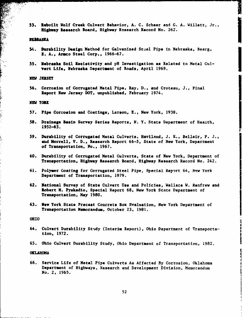
53. Rebuilt Wolf Creek Culvert Behavior, A. C. Scheer and G. A. Willett, Jr.,LHighway Research Board, Highway Research Record No. 262.
54. Durability Design Method for Galvanized Steel Pipe in Nebraska, Bearg,E. A., Armco Steel Corp., 1966-67.
55. Nebraska Soil Resistivity and pH Investigation as Related to Metal Cul-vert Life, Nebraska Department of Roads, April 1969.
REp JNKRSEY
56. Corrosion of Corrugated Metal Pipe, Ray, D., and Croteau, J., FinalReport Now Jersey DOT, unpublished, February 1974.
NEW YORK
57. Pipe Corrosion and Coatings, Larson, E., New York, 1938.
58. Drainage Basin Survey Series Reports, N. Y. State Department of Health,1952-63.
59. Durability of Corrugated Metal Culverts, Haviland, J. E., Bellair, P. J.,ehd Morrell, V. D., Research Report 66-5, State of New York, Departmentof Transportation, No., 1967.
60. Durability of Corrugated Metal Culverts, State of New York, Department ofTransportation, Highway Research Board, Highway Research Record No. 242.
61. Polymer Coating for Corrugated Steel Pipe, Special Report 64, New YorkDepartment of Transportation, 1979.
62. National Survey of State Culvert Use and Policies, Wallace W. Renfrew andRobert M. Pyskadio, Special Report 68, New York State Department ofTransportation, May 1980.
63. New York State Precast Concrete Box Evaluation, New York Department ofTransportation Memorandum, October 23, 1981.
OHIO
64. Culvert Durability Stzdy (Interim Report), Ohio Department of Transporta-tion, 1972.
65. Ohio Culvert Durability Study, Ohio Department of Transportation, 1982.
O-LAHOMA
66. Service Life of Metal Pipe Culverts As Affected By Corrosion, OklahomaDepartment of Highways, Research and Development Division, MemorandumNo. 2, 1965.
52

17. A Study of the Durability of Corrugated Steel Culverts in Oklahoma, C. J.Naves, Oklahoma Department of Highways, 1971.
68. Culvert Inspection, Oregon and Washington, unpublished report, authorunknown. Aruco Drainage and Metal Products Co., Inc., Portland, Oregon,1932.
69. Culvert Inlet Failures - A Case History, Roy C. Edgerton, Oregon State
Highway Department, 1961.
70. Conditi4)n Survey Report, Asbestos-Bonded Steel Culverts in Western Ore-gon, Sol Deocaupo, Terry Gruber and Bruce Wasill, Federal Highway Admin-Istration, 1976.
PMIMSYLVANIA
71. Culvert Pipe Survey, State of Pennsylvania, Department of Highways, 1930(approximate).
UTAH
72. Evaluation of Aluminum Alloy Pipe for Use in Tah's Highways, Peterson,D. E., Utah State Highway Department, June 1973.
73. Pipe Corrosion and Protective Coatings, Utah State Department of High-ways, 1974.
VIRGINIA
74. An Investigation of Bituminous Coated Corrugated Metal Pipe, Sheppe,R. L., Viginia Department of Highways, Division of Tests, Research Sec-tion, November 1946. Confidnetial, unpublished progress report.
75. ComparatIve Study of Aluminum and Steel Culverts: Progress Report No. 1,Mitchell, R. A., Virginia Council of Highway Investigation and Research,October 1962.
76. Comparative Study of Aluminum and Steel Culvarts: Progress Report No. 2,Turner, T. F., Virginia Council of Highway Investigation and Research,November 1963.
77. Comparative Study of Aluminum and Steel Culverts: Progress Report No. 3,McKeel, W. T., Jr., and Turner, T. F., Virginia Council of HighwayInvestigation and Research, February 1965.
7F. A Comparative Study of Aluminum and Steel Culverts: McKeel, W. T., Jr.,Culvert Studies Progress Rep. No. 4, Virginia Highway Research Council,May 1971.
53

79. Culvert Inspection, Oregon and Washington, unpublished report, authoruikuown, Armco Drainage and Metal Products Co., Inc., Portland, Oregon,
S1032.80. State Wide Culvert Survey, Smith, Frederick, C., unpublished report,
State of Washington, Department of Highways, 1937. !81. A Culvert Material Performance Evaluation in the State of Washington,
"N. R. Berg, Department of Highways, Washington State Highway Commission,Research Project No. HPR-1-2, 1965.
W2Xr VIRGINIA
82. Corrugated Metal Culvert ripe Test Using Highly Acid Mine Waters, StateRoad Comission of West Virginia, Division of Tests, 1928-29, Unpublished
k confidential.
83. A Survey of Culverts in West Virginia, Downs, W. S., Research BulletinNo. 13. West Virginia University Engineering Experiment Station,December 15, 1934.
54

APPENDIX A
PROPOSED AASHTO DESIGN PROCEDURE
SECTION 18
k •SOIL - TM OPLASTIC PIPE INTERACTION SYSTEMS
GENERUAL
18.1.1 Scope
The specifications of this section are intended for the structural designof plastic pipes. It must be recognized that a buried plastic pipe is a com-
peelte s-ructure smade up of the plastic ring and the soil envelope, and that
botb materials play a vital part in the structural design of plastic pipe.
18.1.2 Notations
A - required wall area (Article 18.2.1)
A - area of pipe wall (Article 18.3.1)
6 water bouyancy factor (Articles 18.2.2 and 18.3.2)
€ distance from inside surface to neutral axis (Articles 18.2.2, 18.3.2and 18.4.2)
D * effective diaxmter - ID + 2cII"I - modulus of elasticity of pipe mata:rial (Articles 18.2.2 and 18.3.2)
IF - flexibility factor (Articles 18.2.3 and 18.3.3)
f - allowable stress-specified minimum tensile strength divided by safetya factor (Article 18.2.1)
f " critical buckling stress (Articles 18.2.2 and 18.3.2)crf - specified sinimm tensile strength (Articles 18.2.1, 18.3.1 and 18.3.2)UI
I - moment of inertia, per unit length, of cross section of the pipe wall(Articles 18.2.2 and 18.3.2)
ID a inside diameter (Articles 18.2.2, 18.3.2 and 18.4.2)
K a soil modulus (Articles 18.2.2, 18.3.2 and 18.4.2)5
OD - outside diameter (Article 18.4.2)
P - design load (Article 18.1.4)
A-1
-L nnhMMr"_f I-mm•s.•~ •1 ' .q,,dmTM ~~l•r . ,••,)
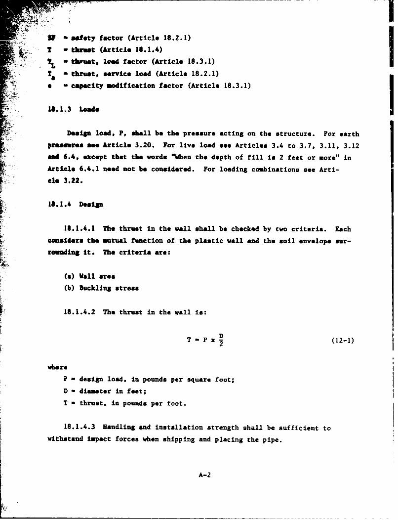
IV* safety factor (Article 18.2.1)
I thrust (Article 18.1.4)I2L thiust, load factor (Article 18.3.1)
To thrust, service load (Article 18.2.1)
9 - capacity modification factor (Article 18.3.1)
18.1.3 Loads
Design load, P, shall be the pressure acting on the structure. For earth
pressures see Article 3.20. For live load see Articles 3.4 to 3.7, 3.11, 3.12
sad 6.4, except that the words "When the depth of fill is 2 feet or more" inArticle 6.4.1 need not be considered. For loading combinations see Arti-
cle 3.22.
18.1.4 Desip
18.1.4.1 The thrust in the wall shall be checked by two criteria. Each
considers the mutual function of the plastic wall and the soil envelope sur-
rounding it. The criteria are:
(a) Wall area
(b) Buckling stress
18.1.4.2 The thrust in the wall is:
T - x D (12-1)
where
P - design load, in pounds per square foot;
D - diameter in feet;
T - thrust, in pounds per foot.
18.1.4.3 Handling and installation strength shall be sufficient to
withstand impact forces when shipping and placing the pipe.
A-2

.tsmaterials
Th, materials shall conform to the AASHTO and ASTh specifications refer-Semeed herein.
18.1.6 Soil Design
18.1.6.1 Soil Parameters
The performance of a flexible culvert is dependent on soil structure
- - Interaction and soil stiffness.
The following must be considered:
(1) The type and anticipated behavior of the foundation soil must be
considered; i.e., stability for bedding and settlement under load.
(2) The type, compacted density, and strength properties of the soil
envelope Imediately adjacent to the pipe must be established.
Good side fill is obtained from a granular material with little or
no plasticity and free of organic material, i.e., AASHTO classifica-
tion groups A-1, A-2. and A-3, compacted to a minimum 90 percdnt of
standard density based on AAHTU_ specirications TT99 (AS D698).
(3) The density of the embankment material above the pipe must be
determined. See Article 6.2.
L (b) Dimensions of soil envelope
The general recommended criteria for lateral limits of the culvert soil
envelope are as follows:
(1) Trench installations - 2 feet minimum each side of culvert. This
recommended limit should be modified as necessary to account for vari-
ables such as poor in-situ soils. I(2) Embankment installations - one diameter each side of culvert.(3) The minimum upper limit of the soil envelope is one foot above the
culvert.
A-3
- II I-

11.? Abrasive or Corrosive Conditions
bttra thckness may be required for resistance to abrasion. For highly
abraelve conditions, a special design may be required.
18.1.3 Minizum Spacing
Mben multiple lines of pipes greater than 48 inches in diameter are ured,
they shall be spaced so that the sides of the pipe shall be no closer than
ne-half diameter or 3 feet, whichever is less, to permit adequate compaction
of baekflfl material. For diameters up to and including 48 inches, the mini-
s : spacing shall not be less than 2 :eet.
18.1.9 Bad Treatment
Protection of end slopes may require special consideration where backwater
conditions may occur, or where erosion and uplift could be a problem. Culvert
snds constitute a major run-off-the-road hazard if not properly designed.
Safety trsatmat, such as structurally adequate grating that conforms to the
embukmant slope, extension of culvert length beyond the point of hazard, or
provision of guardrails, are among the alcernatives to be considered. End
walls on skewed alignment require a special design.
18.1.10 Construction and Installation
The construction and installation shall conform to Section 23 - Divi-
sion II.
18.2 SERVICE LOAD DESIGN
Service Load Design is a working stress method, as traditionally used for
culvert d@sign.
A-4

.2.1L Val1 Area
A T /fa a
Ubere
A " required vall area in square inches per foot
5T thrust, sarvice load in pounds per foot
fa allowable stress-specified minimum tensile strength, pounds persquare inch, diyided by safety factor, fu/SFý
18.2.2 Buckling
Vails with the required wall area, A, shall be checkad for possible
WWIbu ing. If the allowable buckling stress, f /SF, is less than f , thecr a
required area mast he recalculated using f cr/SF in lieu of f a The formula•-- . for bucklinS is:
f cr -0.1d (121/A) DX O.14
lwhre
3 - water buoyancy factor
- i-0.33h lbh
*hw - height of water surface above top of pipe
h - height of ground surface above top of pipe
I - Long term (50-year) modulus of elasticity of the plastic in poundsper square inch;
N a soil modulus in pounds per square inch
- 1700 for side fills meeting Article 18.1.6
f = critical buckling stress in pounds per square inchcrR - effective radius
- c + ID/2
I - moment of inertia of the pipe wall per unit length of cross
section, in4 /fin.
A-5
k. .. • • • !

I-. ,3 Imd~m li and Installation Strength
Bedlimte amid Installation rigidity is measured by a flexibility factor.
IV. datermload by the formula
27F-D 2/EI
O• ubre
VI - flexibility factor in inches per pound;
De a effective diameter in inches;
I - modulus of elasticity of the pipe material in pound& per square inch;
I - moment f tInertia per unit length of cross section of the pipe wallIn Inches to the 4th power per inch.
18.3 LOAD FACTOR DESIGN
Load Factor Design is an alternative method of design based on ultimate
strength principles.
15.3.1 Wall Area
A - TL/ofu
where
A - area of pipe wall in square inches per foot;
TL- thrust, load factor in pounds per foot;
f u- specified minium tensile strength in pounds pcr square inch;
o - capacity modification factor.
18.3.2 Suckling
If f Is less than f u .A must be recalculated using f in lieu of feffr slestnfu' cr u
The forvq• for bucklinX is:
f cr 0.77 (12R/A) ýBms EI/0.1493
A-6

S*water buoyancy Zactor*140.33h hb
bV% heglht of water surface above top of pipe
h - keliht of ground curface above top of pipe
* 3| * Linmg term (50-year) modulus of elasticity of the plastic in poundsper square inch;
X - soil modules In pounds per square inch
- 1700 for side fills meeting Article 18.1.6
a Critical buckling stress in pounds ner square Ii ch;a!L - effective radius
- walmnt of inertia of the pipe wall per unit length of cross
section, in4/in.
18.3.3 sandling and Installation Strength
Ekmdliug rigidity is measured by a flexibility factor, FF, determined by
the formula
FF - D 2 /EI
wbete
77 flexibility factor in inches per pound;
D a effective diameter or maximum span in inches;
I modulus of elasticity of the pipe material in pounds per square inch;
I - moment of inertia per unit length of cross section of the pipe vallin inches to the 4th power per inch.
18.4 PLASTIC PIPE
18.4.1 General
18.4.1.1 Plastic pipe may be smooth wall, corrugated or externally ribbed
and may be manufactured of polyethylene (PE) or poly (vinyl chloride) (PVC).
The material specifications are:
A-7
- -M-: UifrM|b=L -KW

"13~ythule" (Pit)
@hVooch - AIdM F714 Polyethylene (PE) Plamtic Pipe (SDE-PR) Based on
Outside Diameter
Corrugated - AASRTO 11294 Corrugated Polyethylene Pipe, 12 to 24 in.
Diamieter
Ribbed AGIN- T 894 Polyethylene (PE) Large Diameter Profile Wall
Semr and Drain Pipe
Poly (Vinyl Chloride) (PVC)
IF�o eth Vail - M8KO 11278 Class PS 50 Polyvinyl Chloride (PVC) Pipe,
*8NT 1679 Poly (Vinyl Chloride) (PVC) Large-Diameter
Plastic Gravity Sever Pipe and Fittings
Ribbed - A Fth 1794 Poly (Vinyl Chloride) (PVC) Large-Diameter
Ribbed Gravity Sever Pipe and Fittings Based on Controlled
Inside Diameter
18.4.1.2 Service load design - safety factor, SF:
Vall area - 2.0
Buckling - 2.0
18.4.1.3 Load factor design - capacity modification factor, o:
,o = 0.63
PVC, o - 0.65
18.4.1.4 Flexibility Factor
PR, FT - 9.5 z 10-2
PVC, F• - 9.5 x 10⁻²
Note: PE and PVC are thermoplastics and, therefore, subject to reduction
in stiffness as temperature is increased.
18.4.1.5 Minimum Cover
The minizam cover for design loads shall be one-eighth of the inside
diaeter but not less than 12 inchzes. (The minimum cover shall be measured
from the top of a rigid pavement or the bottom of a flexible pavement.) For
construction requirements, see Article 23.10 -Division II.
A-8

• ILAAl.6 Mauxim Strain
2M allowable deflection of installed plastic pipe may be limited by the
=rI m fiber tensile strain of the pipe wall. Calculation of the tension
" tnin in a pipe significantly deflected after installation cta be checked
against the allowable long tera'strain for the material in Article 18.4.3.laspraaeoa thrust La deducted from deflection bending stress to obtain net
te-slon action. The allowable long tern strains shown in 18.4.3 should not be
re•thed in pipes designed and constructed in accordance ".ith this
Spec if icat ion.
18.4.!.7 Local Buckling
The manufacturers of corrugated and ribbed pipe should demonstrate the
adeqiacy of their pipes against local buckling when designed and constructed
in accordance with this specification.
18.4.2 Section Properties
18.4.2.1 PE Corrugated Pipes
O.D. cI.D. (in.) A (in.) 41
I&. (Typical) (sq in./ft,) (Maximum) (in. /in.)
12 14.0 1.50 0.625 0.02415 17.7 1.91 0.375 0.05318 21.1 2.34 0.851 0.06224 27.5 3.14 1.134 0.116
A-9

18.4.2.2 PE Ribbed Pipes
ID. O.D. A c_ I(in.) (sq in./ft) (in.) (in. 4/in.)
18 21.0 2.964 0.344 0.05218 21.0 4.668 0.429 0.08121 24.0 4.152 0.409 0.070I
21 24.2 5.906 0.520 0.12524 27.0' 4.668 0.429 0.08124 27.2 5.906 0.520 0.12527 30.2 5.904 0.520 0.12527 30.3 6.996 0.594 0.16130 33.2 5.904 0.520 0.12530 33.5 8.088 0.640 0.20233 36.3 6.996 0.594 0.16133 37.2 7.812 0.714 0.277"36 39.5 8.088 0.640 0.202
36 40.3 8.820 0.786 0.33842 46.2 7.812 0.714 0.27742 47.1 9.648 0.837 0.524
48 52.3 8.820 0.786 0.33848 53.1 9.648 0.837 0.52454 59.1 9.648 0.837 0.52454 59.4 11.688 0.963 0.72860 65.1 9.648 0.837 0.52460 65.7 13.224 0.998 0.86864 71.4 11.688 0.963 0.72866 72.0 15.036 1.019 1.01472 77.4 11.688 0.963 0.72872 78.4 17.880 1.079 1.28578 83.7 13.224 0.998 0.86878 84.4 17.880 1.079 1.28584 90.0 15.036 1.019 1.01484 91.3 24.120 1.210 1.85090 96.4 17.880 1.079 1.28590 97.3 24.120 1.210 1.85096 102.4 17.880 1.079 1.'3596 103.5 25.800 1.280 2.130
A-10

18.4.2.3 PVC Ribbed Pipes
•.D. O.D. A c 41Un-) (in.) (sq in./ft) (in.) (in. /in.)
17.65 19.1 6.149 0.278 0.016720.75 22.2 6.149 0.278 0.016720.75 22.5 7.421 0.329 0.034623.50 25.2 7.421 0.329 0.034623.50 25.5 8.534 0.376 0.064326.50 28.0 6.056 0.250 0.022526.50 28.5 8.534 0.376 0.06,_326.50 28.7 9.865 0.432 0.090729.50 31.2 6.532 0.313 0.029729.50 31.7 9.865 0.432 0.090735.50 37.3 7.920 0.346 0.040035.50 37.9 11.426 0.480 0.122641.50 43.7 9.760 0.432 0.090747.50 49.9 10.518 0.453 0.1492
18.4.3 Chemical and Mechanical Requirements
The polyethylene (PE) and poly (vinyl chloride) (PVC) materials described
herein have stress/strain relaitonships that are nonlinear and time dependent.
Minimum 50 ýear tensile strengths are derived from hydrostatic design bases
and indicate a minimum 50 year life expectancy under continuous application of
that stress. Minimum 50 year modulii o nor indicate a softening of Lhe pipe
material but is an expression of the time dependent relation between stress
and strain. For each short term increment of deflection, whenever it occurs,
the response will reflect the initial modulus. Both short and long term prop-
erties are shown. Except for buckling, the judgement of the engineer shall
determine which is appropriate for the application.
18.4.3.1 Polyethylene
18.4.3.1.1 Smooth wall PE pipe requirevents - ASTM F714
Mechanical proporties for design
Initial 50 YearMinixuum Minimum Minimum Minimum
Tensile Strength Hod. of Elast. Tensile Strength Mod. of Elast.(psi)si) (psi) (psi)3,000 110,000 1,440 22,000
A-1l

Minimum cell class, ASTM D3350, 335434C
Allowabl, long term strain - 5%
18.4.3.1.2 Corrugated PE pipe requirements - ASTM M294
Mechanical properties for desiqn
Initial 50 YearMninumu Minimum Minimum Minimum
Tensile Strength Mod. of Elast, Tensile Strength Mod. of Elast.(psi) (psi) (psi) (psi)3,000 110,000 900 22,000
Minimum cell class, ASTM D3350, 315412C
Allowable long term strain - 5%
18.4.3.1.3 Ribbed PE pipe requirements - ASTM F894
Mechanical properties for design
Initial 50 YearMinimum Minimum Minimum Minimum
Tensile Strength Mod. of Elast. Tensile Strength Mod. of Elast.(p (psi) (psi) (psi)3, 80,000 1,125 20,000
Minimum cell class, ASTM D3350, 334433C
Allowable long term strain - 5%
OR:
Initial 50 YearMinimum Minimum Minimum Minimum
Tensile Strength Mod. of Elast. Tensile Strength Mod. of Elast.(psi) (psi) (psi) (psi)3,000 110,000 1,440 22,000
Minimum cell class, ASTM D3350, 335434C
Allowable long term strain - 5%
18.4.3.2 Poly(Vinyl Chloride) (PVC)
A-12

16.4.3.2.1 Smooth wall PVC pipe requirements - AASHTO M278, ASTM F679
4 •Mechanical properties for design
Initial 50 Yearminimal Minitmu Minimum Minimum
Tensile Strength Mod. of Elast. Tensile Strength Mod. of Elast.i(psi) (psi) (psi)
7,000 400,000 3,700 140,000
Minimum cell class, ASTM D1784, 12154C
Allowable long term strain - 5%
OR:
Initial 50 YearMinimum Minimum Minimum Minimum
Tensile Strength Mod. of Elast. Tensile Strength Mod. of Elast.(psi) (psi) (psi) (psi)6,000 500,000 2,600 180,000
Minimum cell class, ASTM D1784, 12364C
Allowable long term strain - 3.5%
18.4.3.2.2 Ribbed PVC pipe requirements - ASTM F794
Mechanfral puopertiLes for daa1gn
Initial 50 YearMinimum Minimum Minimum Minimum
Tensile Strength Mod. of Elast. Tensile Strength Mod. of Elast.(psi) (psi) (psi) (psi)7,000 400,000 3,700 140,000
Minimum cell class, ASTM D1784, 12454C
Allowable long term strain - 5%
OR:
AI
A-i13

. Initial 50 YearMindaui mum Minimum Minimum
Tmaild Strength Mod. of Elast. Tensile Strength Mod. of Elast.(psi) (psi) (psi)
6,000 500,000 2,600 180,000
Minimum cell class, ASTM D1784, 12364C
Allowable long term strain - 3.5%
I
A-14


![Pageflex Server [document: D-9E386494 00001] - Morgan de Vere · Morgan de Vere & Partners LLP is a financial planning practice based in Flitwick, central Bedfordshire. Our team of](https://static.fdocuments.us/doc/165x107/5e81e1fbc604d668cc116bc2/pageflex-server-document-d-9e386494-00001-morgan-de-vere-morgan-de-vere-.jpg)