
Life cycle assessment of low power solar inverters (2.5 to...
21
Uster, 3 October 2016 Life cycle assessment of low pow- er solar inverters (2.5 to 20 kW) Authors Laura Tschümperlin, Philippe Stolz, Rolf Frischknecht commissioned by Swiss Federal Office of Energy SFOE
-
Upload
truongduong -
Category
Documents
-
view
218 -
download
4
Transcript of Life cycle assessment of low power solar inverters (2.5 to...

Uster, 3 October 2016
Life cycle assessment of low pow-er solar inverters (2.5 to 20 kW)
Authors
Laura Tschümperlin, Philippe Stolz, Rolf Frischknecht
commissioned by
Swiss Federal Office of Energy SFOE

Imprint
Title Life cycle assessment of low power solar inverters (2.5 to 20 kW)
Authors Laura Tschümperlin, Philippe Stolz, Franziska Wyss, Rolf Frischknecht
treeze Ltd., fair life cycle thinking
Kanzleistr. 4, CH-8610 Uster
www.treeze.ch
Phone +41 44 940 61 91, Fax +41 44 940 61 94
Commissioner Swiss Federal Office of Energy SFOE
Copyright All content provided in this report is copyrighted, except when noted otherwise. Such infor-
mation must not be copied or distributed, in whole or in part, without prior written consent of
treeze Ltd. or the customer. A provision of this report or of files and information from this
report on other websites is not permitted. Any other means of distribution, even in altered
forms, require the written consent. Any citation naming treeze Ltd. or the authors of this
report shall be provided to the authors before publication for verification.
Liability Statement Information contained herein have been compiled or arrived from sources believed to be
reliable. Nevertheless, the authors or their organizations do not accept liability for any loss or
damage arising from the use thereof. Using the given information is strictly your own re-
sponsibility.
Version 174-Update Inverter_IEA PVPS_v1.1, 03.10.2016 15:37:00

Life cycle assessment of low power solar inverters (2.5 to 20 kW) treeze Ltd.
Abbreviations and Acronyms
a year (annum)
CH Switzerland
GLO global average
GWP global warming potential
CED cumulative energy demand
LCA life cycle assessment
LCI life cycle inventory analysis
LCIA life cycle impact assessment
MJ megajoule
PM particulate matter
PV photovoltaic
RER Europe
tkm tonne kilometre (unit for transportation services)

Life cycle assessment of low power solar inverters (2.5 to 20 kW) treeze Ltd.
Summary
The technology used in inverters changed significantly in the past decade, which is why
new life cycle inventories of solar inverters currently sold are established in this study.
Based on information provided by three leading European producers an average inverter
inventory was generated, which was then extrapolated to the following capacities:
2.5 kW, 5 kW, 10 kW, and 20 kW. Extrapolation was done using a non-linear mass
versus power relationship as reported in scientific literature.
The new datasets are intended to replace the current ecoinvent inventory dataset on the
2.5 kW inverter.
The functional unit is one inverter (with a lifetime of 15 years). The inventories include
the energy used for production and mounting, all components of the inverter and their
upstream transportation, production processes, packaging and the disposal of packaging
material and of the product itself after the use phase.
The environmental impacts of the production and disposal of inverters are analysed re-
garding “climate change”, “human toxicity (cancer effects)”, “human toxicity (non-
cancer effects)”, “particulate matter”, “freshwater ecotoxicity” as well as “mineral,
fossil and renewable resource depletion” and the main contributors to the environmental
impacts of inverters are identified.
The printed board assembly causes the biggest environmental impacts, followed by the
individual electronic components and the metals (copper, aluminium). Environmental
impacts due to packaging, infrastructure, metal processing, transportation of raw mate-
rials and the treatment of different waste streams have negligible impacts. The energy
used during production and mounting is at maximum responsible for 1.5 % of the total
impact. Within the printed board assembly the integrated circuit, logic type, is the key
driver of the environmental impacts of the solar inverter. The environmental impacts of
the 2.5 kW inverter analysed in this study, which represents current technology, are
higher than of the 2.5 kW inverter analysed ten years ago.
When discussing and comparing the results, it should be taken into account that the data
availability was rather poor, requiring extrapolations and thus leading to considerable
uncertainties in the generated solar inverter inventories. Nevertheless, it is recommend-
ed to use the updated life cycle inventories of solar inverters since the data quality is
deemed more robust compared to the old 2.5 kW inverter.

Life cycle assessment of low power solar inverters (2.5 to 20 kW) treeze Ltd.
Content
1 INTRODUCTION 1
2 OBJECTIVE AND SCOPE 2
2.1 Objective 2
2.2 Functional unit and system boundaries 2
2.3 Data sources 2
2.4 Impact assessment indicators 3
3 LIFE CYCLE INVENTORIES 4
3.1 Characterisation of the solar inverters 4
3.2 Manufacturing and disposal of solar inverters 4
4 LIFE CYCLE IMPACT ASSESSMENT 8
4.1 Overview 8
4.2 Comparison of solar inverters regarding the six impact categories 8
4.2.1 Climate change 8
4.2.2 Human toxicity, cancer effects 9
4.2.3 Human toxicity, non-cancer effects 10
4.2.4 Particulate matter (PM) 11
4.2.5 Freshwater ecotoxicity 12
4.2.6 Mineral, fossil and renewable resource depletion 13
5 DATA QUALITY AND UNCERTAINTY 15
ACKNOWLEDGEMENT 16
REFERENCES 16

Introduction 1
Life cycle assessment of low power solar inverters (2.5 to 20 kW) treeze Ltd.
1 Introduction
Low power solar inverters transform direct electric current (DC) into alternating electric
current (AC) and transform the electricity to low-voltage (230 V), which then allows the
current to be fed into the grid (Jungbluth et al. 2012). Life cycle inventories of three
different types of solar inverters (500 W, 2‘500 W, 500 kW) are available in the KBOB
life cycle inventory database v2.2:2016 (KBOB et al. 2016). The data underlying these
inventories however was derived from equipment sold and installed ten and more years
ago. The technology used in inverters changed significantly since then. That is why,
new life cycle inventories of inverters currently sold were established.

Objective and Scope 2
Life cycle assessment of low power solar inverters (2.5 to 20 kW) treeze Ltd.
2 Objective and Scope
2.1 Objective
The objective of this study is to compile life cycle inventories of different power scales
of solar inverters. Average life cycle inventories of low power solar inverters are
compiled based on information provided by three leading European producers. Based on
the data obtained, average life cycle inventories for inverters of 2.5 kW, 5 kW, 10 kW
and 20 kW are generated. The life cycle inventory of the 500 W solar inverter has not
been updated because no manufacturer, which delivered data, produces a 500 W
inverter. The 500 kW inverter inventory is not updated because no data has been
provided for high power inverters. Furthermore, their composition differs too much
from low power inverters to allow extrapolation.
The environmental impacts caused by the solar inverters analysed in this study are
assessed and compared with the environmental impacts of the existing 2.5 kW inverter.
Moreover, the most relevant processes and materials contributing to the environmental
impacts of the low power solar inverter are identified.
2.2 Functional unit and system boundaries
The functional unit of this analysis is one solar inverter of a given power output (with a
lifetime of 15 years).
The product system includes the supply of materials and energy used in the production
and mounting, the production processes, packaging and the disposal of packaging
material and of the product itself after the use phase.
2.3 Data sources
A questionnaire was sent to several of the major inverter manufacturers in Europe in
order to obtain data on currently produced inverters. Data on the production of one or
several inverter models of different power output (2.5-20 kW) was obtained from three
producers. The data gathered differ considerably in the level of detail. All producers
provided information on the size and weight of the printed board assembly, which is the
printed wiring board including all mounted components. However, only one
manufacturer specified each mounted component on their printed board assembly.
Hence it was assumed that all printed board assemblies are composed of the same
components and only differ in total weight and size. The same has been done for
individual components other than the metals copper, aluminium and steel (such as
plugs, cables, polypropylene, inductor etc.), because only one manufacturer indicated all
individual components that are part of the inverter but not mounted to the printed board
assembly.
Since one manufacturer provided data on different inverter models, an average inverter
has been compiled for this manufacturer extrapolating the data of each inverter to a

Objective and Scope 3
Life cycle assessment of low power solar inverters (2.5 to 20 kW) treeze Ltd.
common power output. The average inventories presented in this study have been
compiled extrapolating the three inverters of the three manufacturers to a common
power scale, which has then been extrapolated again to the power outputs of 2.5 kW,
5 kW, 10 kW and 20 kW. Extrapolation of the inverter mass (M) as a function of its
power output (P) was done using the following formula for generators proposed by
Caduff et al. (2011):
M = a * Pb,
where a = varying for the generation of the average inverter depending on the
manufacturer’s inverter model weight, a = 6.03 for the extrapolation of the average
inverter to the different power outputs, and b = 0.68.
Extrapolation using this formula reflects a non-linear mass versus power relationship.
The specific mass of inverters per power output in general decreases with an increasing
nominal AC power (Jungbluth et al. 2012).
The life cycle inventories are embedded in the KBOB life cycle inventory database
v2.2:2016 (KBOB et al. 2016), which is based on ecoinvent data v2.2, and the analyses
were performed with SimaPro v8.0.6 (PRé Consultants 2015).
2.4 Impact assessment indicators
The environmental impacts are quantified with selected impact category indicators of
the ILCD Midpoint 2011 impact assessment method, excluding long-term impacts
(European Commission et al. 2012). This method was released in 2012 by the European
Commission, Joint Research Centre and includes 19 midpoint impact categories. This
study focuses on the following six impact categories previously identified as most rele-
vant for the generation of PV electricity (Stolz et al. 2016):
- climate change,
- human toxicity (cancer effects),
- human toxicity (non-cancer effects),
- particulate matter,
- freshwater ecotoxicity,
- mineral, fossil and renewable resource depletion.

Life Cycle Inventories 4
Life cycle assessment of low power solar inverters (2.5 to 20 kW) treeze Ltd.
3 Life Cycle Inventories
3.1 Characterisation of the solar inverters
Inverters usually consist of a transformer, electronic components as control units, a case
and some connectors (Jungbluth et al. 2012). Besides the production of the inverters the
life cycle inventories include external packaging and the disposal of production waste
and of the inverter itself at the end of life. At the end of life, the printed board assembly
and the metals (aluminium, steel, copper) are recycled, whereas plastics and cardboard
waste from packaging are burnt in municipal waste incineration plants.
Tab. 3.1 shows the characteristics of the inventoried average inverters of different
capacities. The printed board assembly consists of the printed wiring board itself and the
electrical components mounted to the printed wiring board. The total weight is
calculated by adding the weight of the metals, the other individual components and the
printed board assembly. The total weight does not increase linearly with an increase in
power, as a consequence of the scaling factor applied for the extrapolation. In
comparison to the 2.5 kW inverter available in ecoinvent data v2.2 (indicated with
“old”), the new 2.5 kW inverter is lighter, its printed board assembly is smaller and
lighter and less steel and copper are used.
Tab. 3.1: Characteristics of the old 2.5 kW inverter from the ecoinvent database and the average inverter
with the different power outputs 2.5 kW, 5 kW, 10 kW and 20 kW.
3.2 Manufacturing and disposal of solar inverters
All life cycle inventories of the manufacturing and disposal of solar inverters are
structured identically. The inventories list first the energy needed for the production and
mounting of one inverter and the materials for the casing and other individual
components. Individual components include metals, plastics, cables, plugs, inductors
and integrated circuits. Integrated circuits and a smaller amount of inductors, cables and
plugs are also present on the printed board. All inputs listed under printed board
assembly are, in contrast to individual components, fixed to the printed board. The
Type
inverter,
2.5 kW
(old)
Average
inverter,
2.5 kW
Average
inverter,
5 kW
Average
inverter,
10 kW
Average
inverter,
20 kW
Unit [kg] [kg] [kg] [kg] [kg]
Total weight 18.7 11.2 18.0 28.9 46.2
Copper 5.5 1.9 3.1 4.9 7.9
Aluminium 1.4 5.0 8.0 12.8 20.5
Steel 9.8 0.9 1.5 2.3 3.7
Other individual components 0.3 2.2 3.6 5.7 9.2
Printed board assembly 1.7 1.2 2.0 3.1 5.0
Printed wiring board 0.7 0.3 0.5 0.8 1.4

Life Cycle Inventories 5
Life cycle assessment of low power solar inverters (2.5 to 20 kW) treeze Ltd.
printed board assembly includes capacitors, resistors, transformers, connectors,
inductors, transistors, diodes, plugs, cables, some glass fibre reinforced plastic, tin and
ferrite.
Furthermore, metal processing and an infrastructure demand for the machines and the
production plant are included. As already mentioned, different packaging materials are
considered as well as the transport of raw materials to the production site. Finally, the
inventories include data on water usage and the treatment of different waste streams.
The printed board assembly of the manufacturer specifying all components of a printed
board assembly is built with the lead-free surface mount technique (which is more
common nowadays). Therefore the printed boards of the average inventories are also
produced with the surface mount technique. In contrast, the inventory of the old
“inverter, 2500W, at plant” assumes the through-hole mounting technique for the
printed board assembly production.
The transportation demand in tkm of the raw materials has been calculated using
standard transport distances. The average life cycle inventories for inverters with the
capacities of 2.5 kW, 5 kW, 10 kW and 20 kW are shown in Tab. 3.2.
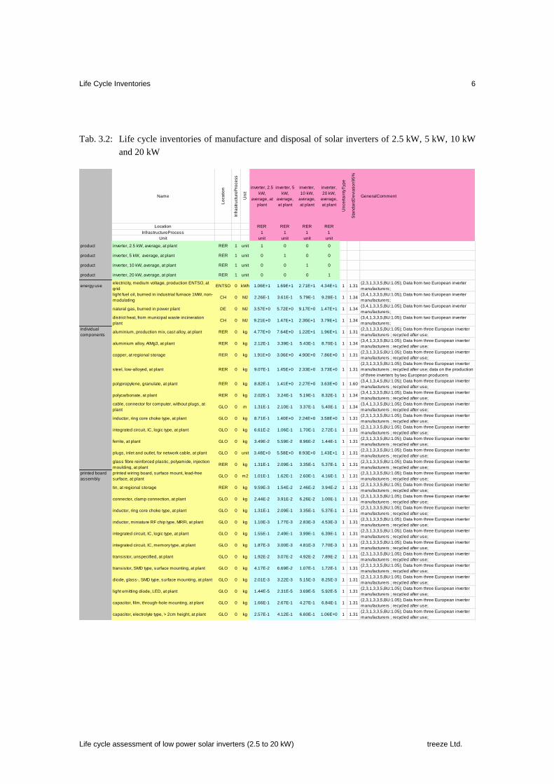
Life Cycle Inventories 6
Life cycle assessment of low power solar inverters (2.5 to 20 kW) treeze Ltd.
Tab. 3.2: Life cycle inventories of manufacture and disposal of solar inverters of 2.5 kW, 5 kW, 10 kW
and 20 kW
Name
Lo
ca
tio
n
Infr
astr
uctu
reP
roce
ss
Un
it
inverter, 2.5
kW,
average, at
plant
inverter, 5
kW,
average,
at plant
inverter,
10 kW,
average,
at plant
inverter,
20 kW,
average,
at plant
Un
ce
rta
inty
Typ
e
Sta
nd
ard
De
via
tio
n9
5%
GeneralComment
Location RER RER RER RER
InfrastructureProcess 1 1 1 1
Unit unit unit unit unit
product inverter, 2.5 kW, average, at plant RER 1 unit 1 0 0 0
product inverter, 5 kW, average, at plant RER 1 unit 0 1 0 0
product inverter, 10 kW, average, at plant RER 1 unit 0 0 1 0
product inverter, 20 kW, average, at plant RER 1 unit 0 0 0 1
energy useelectricity, medium voltage, production ENTSO, at
gridENTSO 0 kWh 1.06E+1 1.69E+1 2.71E+1 4.34E+1 1 1.31
(2,3,1,3,3,5,BU:1.05); Data from two European inverter
manufacturers;
light fuel oil, burned in industrial furnace 1MW, non-
modulatingCH 0 MJ 2.26E-1 3.61E-1 5.79E-1 9.28E-1 1 1.34
(3,4,1,3,3,5,BU:1.05); Data from two European inverter
manufacturers;
natural gas, burned in power plant DE 0 MJ 3.57E+0 5.72E+0 9.17E+0 1.47E+1 1 1.34(3,4,1,3,3,5,BU:1.05); Data from two European inverter
manufacturers;
district heat, from municipal waste incineration
plantCH 0 MJ 9.21E+0 1.47E+1 2.36E+1 3.79E+1 1 1.34
(3,4,1,3,3,5,BU:1.05); Data from two European inverter
manufacturers;
individual
componentsaluminium, production mix, cast alloy, at plant RER 0 kg 4.77E+0 7.64E+0 1.22E+1 1.96E+1 1 1.31
(2,3,1,3,3,5,BU:1.05); Data from three European inverter
manufacturers ; recycled after use;
aluminium alloy, AlMg3, at plant RER 0 kg 2.12E-1 3.39E-1 5.43E-1 8.70E-1 1 1.34(3,4,1,3,3,5,BU:1.05); Data from three European inverter
manufacturers ; recycled after use;
copper, at regional storage RER 0 kg 1.91E+0 3.06E+0 4.90E+0 7.86E+0 1 1.31(2,3,1,3,3,5,BU:1.05); Data from three European inverter
manufacturers ; recycled after use;
steel, low-alloyed, at plant RER 0 kg 9.07E-1 1.45E+0 2.33E+0 3.73E+0 1 1.31
(2,3,1,3,3,5,BU:1.05); Data from three European inverter
manufacturers ; recycled after use; data on the production
of three inverters by two European producers
polypropylene, granulate, at plant RER 0 kg 8.82E-1 1.41E+0 2.27E+0 3.63E+0 1 1.60(3,4,1,3,4,5,BU:1.05); Data from three European inverter
manufacturers ; recycled after use;
polycarbonate, at plant RER 0 kg 2.02E-1 3.24E-1 5.19E-1 8.32E-1 1 1.34(3,4,1,3,3,5,BU:1.05); Data from three European inverter
manufacturers ; recycled after use;
cable, connector for computer, without plugs, at
plantGLO 0 m 1.31E-1 2.10E-1 3.37E-1 5.40E-1 1 1.34
(3,4,1,3,3,5,BU:1.05); Data from three European inverter
manufacturers ; recycled after use;
inductor, ring core choke type, at plant GLO 0 kg 8.71E-1 1.40E+0 2.24E+0 3.58E+0 1 1.31(2,3,1,3,3,5,BU:1.05); Data from three European inverter
manufacturers ; recycled after use;
integrated circuit, IC, logic type, at plant GLO 0 kg 6.61E-2 1.06E-1 1.70E-1 2.72E-1 1 1.31(2,3,1,3,3,5,BU:1.05); Data from three European inverter
manufacturers ; recycled after use;
ferrite, at plant GLO 0 kg 3.49E-2 5.59E-2 8.96E-2 1.44E-1 1 1.31(2,3,1,3,3,5,BU:1.05); Data from three European inverter
manufacturers ; recycled after use;
plugs, inlet and outlet, for network cable, at plant GLO 0 unit 3.48E+0 5.58E+0 8.93E+0 1.43E+1 1 1.31(2,3,1,3,3,5,BU:1.05); Data from three European inverter
manufacturers ; recycled after use;
glass fibre reinforced plastic, polyamide, injection
moulding, at plantRER 0 kg 1.31E-1 2.09E-1 3.35E-1 5.37E-1 1 1.31
(2,3,1,3,3,5,BU:1.05); Data from three European inverter
manufacturers ; recycled after use;
printed board
assembly
printed wiring board, surface mount, lead-free
surface, at plantGLO 0 m2 1.01E-1 1.62E-1 2.60E-1 4.16E-1 1 1.31
(2,3,1,3,3,5,BU:1.05); Data from three European inverter
manufacturers ; recycled after use;
tin, at regional storage RER 0 kg 9.59E-3 1.54E-2 2.46E-2 3.94E-2 1 1.31(2,3,1,3,3,5,BU:1.05); Data from three European inverter
manufacturers ; recycled after use;
connector, clamp connection, at plant GLO 0 kg 2.44E-2 3.91E-2 6.26E-2 1.00E-1 1 1.31(2,3,1,3,3,5,BU:1.05); Data from three European inverter
manufacturers ; recycled after use;
inductor, ring core choke type, at plant GLO 0 kg 1.31E-1 2.09E-1 3.35E-1 5.37E-1 1 1.31(2,3,1,3,3,5,BU:1.05); Data from three European inverter
manufacturers ; recycled after use;
inductor, miniature RF chip type, MRFI, at plant GLO 0 kg 1.10E-3 1.77E-3 2.83E-3 4.53E-3 1 1.31(2,3,1,3,3,5,BU:1.05); Data from three European inverter
manufacturers ; recycled after use;
integrated circuit, IC, logic type, at plant GLO 0 kg 1.55E-1 2.49E-1 3.99E-1 6.39E-1 1 1.31(2,3,1,3,3,5,BU:1.05); Data from three European inverter
manufacturers ; recycled after use;
integrated circuit, IC, memory type, at plant GLO 0 kg 1.87E-3 3.00E-3 4.81E-3 7.70E-3 1 1.31(2,3,1,3,3,5,BU:1.05); Data from three European inverter
manufacturers ; recycled after use;
transistor, unspecified, at plant GLO 0 kg 1.92E-2 3.07E-2 4.92E-2 7.89E-2 1 1.31(2,3,1,3,3,5,BU:1.05); Data from three European inverter
manufacturers ; recycled after use;
transistor, SMD type, surface mounting, at plant GLO 0 kg 4.17E-2 6.69E-2 1.07E-1 1.72E-1 1 1.31(2,3,1,3,3,5,BU:1.05); Data from three European inverter
manufacturers ; recycled after use;
diode, glass-, SMD type, surface mounting, at plant GLO 0 kg 2.01E-3 3.22E-3 5.15E-3 8.25E-3 1 1.31(2,3,1,3,3,5,BU:1.05); Data from three European inverter
manufacturers ; recycled after use;
light emitting diode, LED, at plant GLO 0 kg 1.44E-5 2.31E-5 3.69E-5 5.92E-5 1 1.31(2,3,1,3,3,5,BU:1.05); Data from three European inverter
manufacturers ; recycled after use;
capacitor, film, through-hole mounting, at plant GLO 0 kg 1.66E-1 2.67E-1 4.27E-1 6.84E-1 1 1.31(2,3,1,3,3,5,BU:1.05); Data from three European inverter
manufacturers ; recycled after use;
capacitor, electrolyte type, > 2cm height, at plant GLO 0 kg 2.57E-1 4.12E-1 6.60E-1 1.06E+0 1 1.31(2,3,1,3,3,5,BU:1.05); Data from three European inverter
manufacturers ; recycled after use;

Life Cycle Inventories 7
Life cycle assessment of low power solar inverters (2.5 to 20 kW) treeze Ltd.
Tab. 3.2: Life cycle inventories of manufacture and disposal of solar inverters of 2.5 kW, 5 kW, 10 kW
and 20 kW (continued)
Name
Lo
ca
tio
n
Infr
astr
uctu
reP
roce
ss
Un
it
inverter, 2.5
kW,
average, at
plant
inverter, 5
kW,
average,
at plant
inverter,
10 kW,
average,
at plant
inverter,
20 kW,
average,
at plant
Un
ce
rta
inty
Typ
e
Sta
nd
ard
De
via
tio
n9
5%
GeneralComment
Location RER RER RER RER
InfrastructureProcess 1 1 1 1
Unit unit unit unit unit
capacitor, electrolyte type, < 2cm height, at plant GLO 0 kg 6.71E-3 1.08E-2 1.72E-2 2.76E-2 1 1.31(2,3,1,3,3,5,BU:1.05); Data from three European inverter
manufacturers ; recycled after use;
capacitor, SMD type, surface-mounting, at plant GLO 0 kg 1.33E-3 2.14E-3 3.42E-3 5.49E-3 1 1.31(2,3,1,3,3,5,BU:1.05); Data from three European inverter
manufacturers ; recycled after use;
resistor, wirewound, through-hole mounting, at
plantGLO 0 kg 1.12E-3 1.79E-3 2.87E-3 4.60E-3 1 1.31
(2,3,1,3,3,5,BU:1.05); Data from three European inverter
manufacturers ; recycled after use;
resistor, SMD type, surface mounting, at plant GLO 0 kg 4.57E-3 7.33E-3 1.17E-2 1.88E-2 1 1.31(2,3,1,3,3,5,BU:1.05); Data from three European inverter
manufacturers ; recycled after use;
ferrite, at plant GLO 0 kg 2.55E-5 4.09E-5 6.55E-5 1.05E-4 1 1.31(2,3,1,3,3,5,BU:1.05); Data from three European inverter
manufacturers ; recycled after use;
transformer, low voltage use, at plant GLO 0 kg 4.01E-2 6.43E-2 1.03E-1 1.65E-1 1 1.31(2,3,1,3,3,5,BU:1.05); Data from three European inverter
manufacturers ; recycled after use;
plugs, inlet and outlet, for network cable, at plant GLO 0 unit 2.79E-1 4.47E-1 7.16E-1 1.15E+0 1 1.31(2,3,1,3,3,5,BU:1.05); Data from three European inverter
manufacturers ; recycled after use;
glass fibre reinforced plastic, polyamide, injection
moulding, at plantRER 0 kg 2.56E-2 4.10E-2 6.57E-2 1.05E-1 1 1.31
(2,3,1,3,3,5,BU:1.05); Data from three European inverter
manufacturers ; recycled after use;
cable, ribbon cable, 20-pin, with plugs, at plant GLO 0 kg 2.40E-4 3.84E-4 6.16E-4 9.86E-4 1 1.31(2,3,1,3,3,5,BU:1.05); Data from three European inverter
manufacturers ; recycled after use;
processing sheet rolling, steel RER 0 kg 9.07E-1 1.45E+0 2.33E+0 3.73E+0 1 1.21
(1,1,1,1,1,5,BU:1.05); Data from three European inverter
manufacturers ; recycled after use; Applied as well on the
production data of an inverter of an European producer
wire drawing, copper RER 0 kg 1.91E+0 3.06E+0 4.90E+0 7.86E+0 1 1.21
(1,1,1,1,1,5,BU:1.05); Data from three European inverter
manufacturers ; recycled after use; Applied as well on the
production data of an inverter of an European producer
section bar extrusion, aluminium RER 0 kg 4.77E+0 7.64E+0 1.22E+1 1.96E+1 1 1.21
(1,1,1,1,1,5,BU:1.05); Data from three European inverter
manufacturers ; recycled after use; Applied as well on the
production data of an inverter of an European producer
steel product manufacturing, average metal
workingRER 0 kg 1.92E-2 3.08E-2 4.93E-2 7.90E-2 1 1.34
(3,4,1,3,3,5,BU:1.05); data on the production of an inverter
by a European producer;
infrastructure metal working factory RER 1 unit 1.10E-8 1.76E-8 2.82E-8 4.51E-8 1 3.05
(1,1,1,1,1,5,BU:3); Calculation, based on annual
production of electronic component production plant;
taken from the ecoinvent v2.2 inverter dataset;
packaging corrugated board, mixed fibre, single wall, at plant RER 0 kg 6.60E-1 1.06E+0 1.69E+0 2.71E+0 1 1.21(1,1,1,1,1,5,BU:1.05); data on the production of an inverter
by a European producer;
folding boxboard, FBB, at plant RER 0 kg 1.16E+0 1.85E+0 2.97E+0 4.75E+0 1 1.34(3,4,1,3,3,5,BU:1.05); data on the production of an inverter
by a European producer;
packaging film, LDPE, at plant RER 0 kg 1.15E-2 1.84E-2 2.95E-2 4.73E-2 1 1.34(3,4,1,3,3,5,BU:1.05); data on the production of an inverter
by a European producer;
transport transport, lorry >16t, fleet average RER 0 tkm 6.76E-1 1.08E+0 1.74E+0 2.78E+0 1 2.09(4,5,na,na,na,na,BU:2); Standard distance 60km incl.
disposal;
transport, freight, rail RER 0 tkm 2.25E+0 3.61E+0 5.79E+0 9.27E+0 1 2.09 (4,5,na,na,na,na,BU:2); Standard distances 200km;
transport, transoceanic freight ship OCE 0 tkm 2.03E+1 3.25E+1 5.21E+1 8.34E+1 1 2.09 (4,5,na,na,na,na,BU:2); Estimation: 18000km;
emission air,
unspecifiedHeat, waste - - MJ 3.80E+1 6.09E+1 9.75E+1 1.56E+2 1 1.22 (2,3,1,1,1,5,BU:1.05); Calculation;
technosphere tap water, at user RER 0 kg 1.99E+1 3.18E+1 5.10E+1 8.17E+1 1 1.34(3,4,1,3,3,5,BU:1.05); data on the production of an inverter
by a European producer;
resource, in
waterWater, unspecified natural origin, DE - - m3 3.78E-2 6.06E-2 9.71E-2 1.56E-1 1 1.34
(3,4,1,3,3,5,BU:1.05); data on the production of an inverter
by a European producer;
disposaltreatment, sewage, unpolluted, to wastewater
treatment, class 3CH 0 m3 1.99E-2 3.18E-2 5.10E-2 8.17E-2 1 1.34
(3,4,1,3,3,5,BU:1.05); data on the production of an inverter
by a European producer;
disposal, packaging cardboard, 19.6% water, to
municipal incinerationCH 0 kg 1.82E+0 2.91E+0 4.66E+0 7.47E+0 1 1.25
(2,3,1,5,1,5,BU:1.05); disposal of the packaging
materials;
disposal, polyethylene, 0.4% water, to municipal
incinerationCH 0 kg 1.15E-2 1.84E-2 2.95E-2 4.73E-2 1 1.25
(2,3,1,5,1,5,BU:1.05); disposal of the packaging
materials;
disposal, treatment of printed wiring boards GLO 0 kg 1.22E+0 1.96E+0 3.14E+0 5.02E+0 1 1.25(2,3,1,5,1,5,BU:1.05); Data from three European inverter
manufacturers ; recycled after use;
disposal, municipal solid waste, 22.9% water, to
municipal incinerationCH 0 kg 2.43E-1 3.89E-1 6.23E-1 9.98E-1 1 1.34
(3,4,1,3,3,5,BU:1.05); data on the production of an inverter
by a European producer;
disposal, hazardous waste, 25% water, to
hazardous waste incinerationCH 0 kg 1.28E-2 2.06E-2 3.30E-2 5.28E-2 1 1.34
(3,4,1,3,3,5,BU:1.05); data on the production of an inverter
by a European producer;
Life Cycle Impact Assessment 8
Life cycle assessment of low power solar inverters (2.5 to 20 kW) treeze Ltd.
4 Life Cycle Impact Assessment
4.1 Overview
This chapter contains the environmental impact assessment results and highlights the
main drivers of the environmental impacts of inverters. The impacts are grouped into
seven categories, namely the “printed board assembly (printed board including all
mounted components)”, the metals “copper”, “aluminium” and “steel”, “other individu-
al components (including all components besides the metals not being attached to the
printed board)”, “energy” and “others”. Environmental impacts due to packaging, infra-
structure, metal processing, transportation of raw materials and the treatment of differ-
ent waste streams are aggregated to the category “others” since their individual contri-
butions are small. The energy used during production is at maximum responsible for
1.5 % of the total impact and shown separately.
Since this study compiled inventories of low power solar inverters, the results are com-
pared to the environmental impacts of the old 2.5 kW inverter. The main drivers for
each impact category of the new average inverter are for all inverter capacities the same,
due to the extrapolation made from one average inverter.
4.2 Comparison of solar inverters regarding the six impact categories
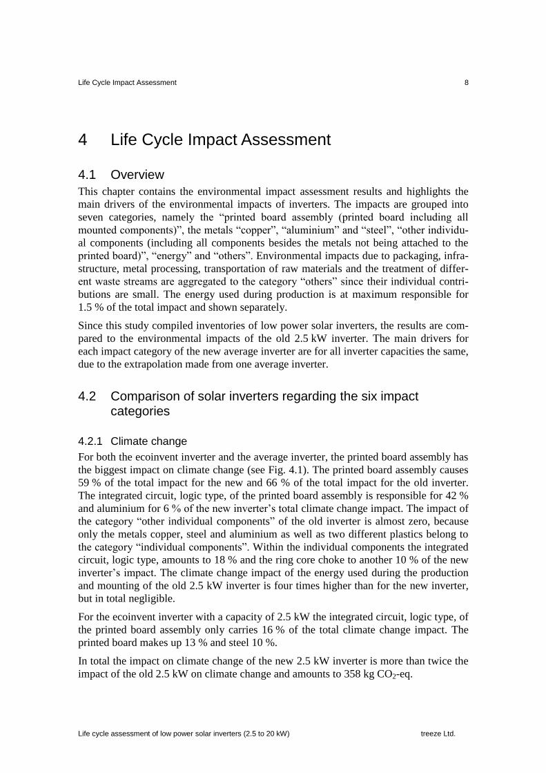
4.2.1 Climate change
For both the ecoinvent inverter and the average inverter, the printed board assembly has
the biggest impact on climate change (see Fig. 4.1). The printed board assembly causes
59 % of the total impact for the new and 66 % of the total impact for the old inverter.
The integrated circuit, logic type, of the printed board assembly is responsible for 42 %
and aluminium for 6 % of the new inverter’s total climate change impact. The impact of
the category “other individual components” of the old inverter is almost zero, because
only the metals copper, steel and aluminium as well as two different plastics belong to
the category “individual components”. Within the individual components the integrated
circuit, logic type, amounts to 18 % and the ring core choke to another 10 % of the new
inverter’s impact. The climate change impact of the energy used during the production
and mounting of the old 2.5 kW inverter is four times higher than for the new inverter,
but in total negligible.
For the ecoinvent inverter with a capacity of 2.5 kW the integrated circuit, logic type, of
the printed board assembly only carries 16 % of the total climate change impact. The
printed board makes up 13 % and steel 10 %.
In total the impact on climate change of the new 2.5 kW inverter is more than twice the
impact of the old 2.5 kW on climate change and amounts to 358 kg CO2-eq.
Life Cycle Impact Assessment 9
Life cycle assessment of low power solar inverters (2.5 to 20 kW) treeze Ltd.
Fig. 4.1: Greenhouse gas emissions of manufacture and disposal of low power solar inverters, quantified
in kg CO2-eq (IPCC 2013,Chapter 8).
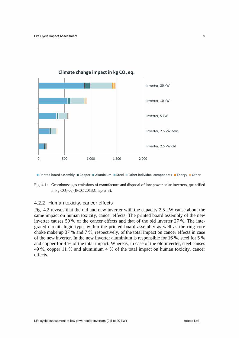
4.2.2 Human toxicity, cancer effects
Fig. 4.2 reveals that the old and new inverter with the capacity 2.5 kW cause about the
same impact on human toxicity, cancer effects. The printed board assembly of the new
inverter causes 50 % of the cancer effects and that of the old inverter 27 %. The inte-
grated circuit, logic type, within the printed board assembly as well as the ring core
choke make up 37 % and 7 %, respectively, of the total impact on cancer effects in case
of the new inverter. In the new inverter aluminium is responsible for 16 %, steel for 5 %
and copper for 4 % of the total impact. Whereas, in case of the old inverter, steel causes
49 %, copper 11 % and aluminium 4 % of the total impact on human toxicity, cancer
effects.
0 500 1'000 1'500 2'000
Inverter, 2.5 kW old
Inverter, 2.5 kW new
Inverter, 5 kW
Inverter, 10 kW
Inverter, 20 kW
Climate change impact in kg CO2 eq.
Printed board assembly Copper Aluminium Steel Other individual components Energy Other

Life Cycle Impact Assessment 10
Life cycle assessment of low power solar inverters (2.5 to 20 kW) treeze Ltd.
Fig. 4.2: Impacts of manufacture and disposal of low power solar inverters on human toxicity, cancer
effects, quantified in µ-CTUh.
4.2.3 Human toxicity, non-cancer effects
In case of the new inverter the printed board assembly has the biggest impact on human
toxicity, non-cancer effects, with 55 % (see Fig. 4.3), while copper dominates the non-
cancer effects of the old inverter by 59 %. Besides copper, the integrated circuit, logic
type, contributes with 11 %, steel with 8 % and the capacitor, film with 6 % to the total
non-cancer effects of the old inverter.
The dominating impacts of the new inverter stem from the integrated circuit, logic type,
of the printed board assembly (45 %), the integrated circuit, logic type, of the individual
components category (19 %), copper (16 %) and aluminium (5 %).
The impact on human toxicity, non-cancer effects, of the new 2.5 kW solar inverter is
30 % higher than the impact of the old 2.5 kW inverter.
0 10 20 30 40 50
Inverter, 2.5 kW old
Inverter, 2.5 kW new
Inverter, 5 kW
Inverter, 10 kW
Inverter, 20 kW
Human toxicity, cancer effects in µ-CTUh
Printed board assembly Copper Aluminium Steel Other individual components Energy Other

Life Cycle Impact Assessment 11
Life cycle assessment of low power solar inverters (2.5 to 20 kW) treeze Ltd.
Fig. 4.3: Impacts of manufacture and disposal of low power solar inverters on human toxicity, non-
cancer effects, quantified in µ-CTUh.
4.2.4 Particulate matter (PM)
The printed board assembly makes up 52 % and the other individual components 26 %
of the total PM emissions of the new inverter (see Fig. 4.4). Within the printed board
assembly the integrated circuit, logic type, emits most with 65 % and within the indi-
vidual components category 58 %. Copper used in the new inverter emits an additional
11 % of particulate matter.
Copper emits 43 %, the integrated circuit, logic type, and steel each 8 % and the capaci-
tor, film 7 % of all particular matter emissions of the old inverter.
The new 2.5 kW solar inverter causes 34 % higher particulate matter emissions than the
old 2.5 kW inverter.
0 200 400 600 800
Inverter, 2.5 kW old
Inverter, 2.5 kW new
Inverter, 5 kW
Inverter, 10 kW
Inverter, 20 kW
Human toxicity, non-cancer effects in µ-CTUh
Printed board assembly Copper Aluminium Steel Other individual components Energy Other

Life Cycle Impact Assessment 12
Life cycle assessment of low power solar inverters (2.5 to 20 kW) treeze Ltd.
Fig. 4.4: Impacts of manufacture and disposal of low power solar inverters on particulate matter, quanti-
fied in kg PM2.5 eq.
4.2.5 Freshwater ecotoxicity
The printed board assembly dominates the impact on freshwater ecotoxicity of both the
new and the old inverter with a share of 67 % and 55 %, respectively (see Fig. 4.5). The
impact on freshwater ecotoxicity of the new 2.5 kW inverter is almost three times as
high as the impact of the old 2.5 kW inverter. The total impact of the old inverter is
dominated by the integrated circuit, logic type (33 %), copper (29 %), the capacitor,
film (10 %), steel (10 %) and the printed board (8 %).
The integrated circuit, logic type of the printed board assembly of the new inverter
causes 61 % and the one of the individual components further 26 % of the total impact
on freshwater ecotoxicity.
0.0 0.1 0.2 0.3 0.4 0.5 0.6 0.7 0.8 0.9
Inverter, 2.5 kW old
Inverter, 2.5 kW new
Inverter, 5 kW
Inverter, 10 kW
Inverter, 20 kW
Particulate matter in kg PM2.5 eq.
Printed board assembly Copper Aluminium Steel Other individual components Energy Other

Life Cycle Impact Assessment 13
Life cycle assessment of low power solar inverters (2.5 to 20 kW) treeze Ltd.
Fig. 4.5: Impacts of manufacture and disposal of low power solar inverters on freshwater ecotoxicity,
quantified in CTUe.
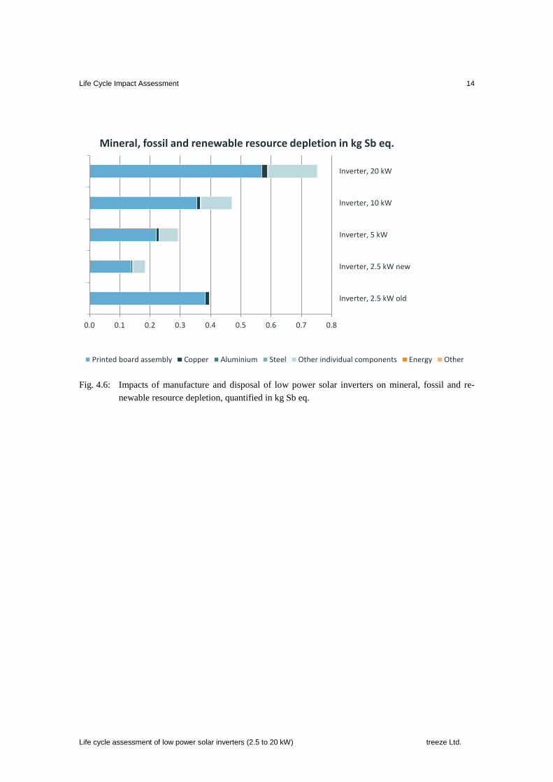
4.2.6 Mineral, fossil and renewable resource depletion
The impact on mineral, fossil and renewable resource depletion of the old 2.5 kW in-
verter is twice as high as the impact of the new 2.5 kW inverter (see Fig. 4.6). 96 % of
the impacts are caused by the printed board assembly used in the old inverter. Within
the printed board assembly, most impact is caused by the capacitor, Tantalum (65 %)
and the capacitor, film (25 %).
The printed board assembly dominates the overall impact of the new inverter as well
with 75 %. The main drivers of resource depletion are the integrated circuit, logic type
of the printed board assembly (42 %), the capacitor, film (27 %) and the integrated cir-
cuit, logic type, of the individual components (18 %).
0 2'000 4'000 6'000 8'000
Inverter, 2.5 kW old
Inverter, 2.5 kW new
Inverter, 5 kW
Inverter, 10 kW
Inverter, 20 kW
Freshwater ecotoxicity in CTUe
Printed board assembly Copper Aluminium Steel Other individual components Energy Other
Life Cycle Impact Assessment 14
Life cycle assessment of low power solar inverters (2.5 to 20 kW) treeze Ltd.
Fig. 4.6: Impacts of manufacture and disposal of low power solar inverters on mineral, fossil and re-
newable resource depletion, quantified in kg Sb eq.
0.0 0.1 0.2 0.3 0.4 0.5 0.6 0.7 0.8
Inverter, 2.5 kW old
Inverter, 2.5 kW new
Inverter, 5 kW
Inverter, 10 kW
Inverter, 20 kW
Mineral, fossil and renewable resource depletion in kg Sb eq.
Printed board assembly Copper Aluminium Steel Other individual components Energy Other

Data quality and uncertainty 15
Life cycle assessment of low power solar inverters (2.5 to 20 kW) treeze Ltd.
5 Data quality and uncertainty
Since not many inverter manufacturers provided data on the production of inverters, the
data quality is rather poor and limited to low power inverters. Furthermore, data of the
different manufacturers differ substantially regarding the weight and the materialisation
of the inverter. There is a trend to produce lighter inverters with less copper1. Hence, all
data gathered have been averaged to build a more robust inventory. For the different
power capacities, the inventory was then extrapolated according to Caduff et al. (2011).
The individual components as well as the mounted components of the printed board
assembly of the average inverter, were not averaged but directly taken from one single
inverter model of one of the three manufacturers providing data. This is a clear
limitation since the printed board assembly, followed by the individual components and
the metals of the new inverters are the main drivers regarding all analysed impact
categories. Hence, the components have a big influence on the total environmental
impacts of an inverter. That is why the new 2.5 kW inverter causes higher
environmental impacts in most impact categories than the old 2.5 kW inverter, although
being lighter in total and having a smaller printed board.
Despite these uncertainties, it is recommended to use the updated life cycle inventories
of solar inverters since the data quality is deemed more robust compared to the old
2.5 kW inverter.
1 Personal communication, European manufacturer of solar inverters, 16.08.2016

Acknowledgement 16
Life cycle assessment of low power solar inverters (2.5 to 20 kW) treeze Ltd.
Acknowledgement
We gratefully acknowledge the kind support of Susanne Schidler, Technikum Wien, in
the data collection for the life cycle assessment of solar inverters.
References Caduff et al. 2011 Caduff M., Huijbregts M. A. J., Althaus H.-J. and Hendriks A. J.
(2011) Power-Law Relationships for Estimating Mass, Fuel Con-
sumption and Costs of Energy Conversion Equipments. In: Envi-
ronmental Science & Technology, 45(2), pp. 751-754.
European Commission et al. 2012 European Commission, Joint Research Centre and Institute for
Environment and Sustainability (2012) Characterisation factors of
the ILCD Recommended Life Cycle Impact Assessment methods.
Database and Supporting Information. First Edition. Publication
Office of the European Union, Luxembourg.
IPCC 2013 IPCC (2013) The IPCC fifth Assessment Report - Climate Change
2013: the Physical Science Basis. Working Group I, IPCC Secre-
tariat, Geneva, Switzerland.
Jungbluth et al. 2012 Jungbluth N., Stucki M., Flury K., Frischknecht R. and Buesser S.
(2012) Life Cycle Inventories of Photovoltaics. ESU-services Ltd.,
Uster, CH, retrieved from: www.esu-services.ch.
KBOB et al. 2016 KBOB, eco-bau and IPB (2016) KBOB-Empfehlung 2009/1:2016:
Ökobilanzdaten im Baubereich, Stand Juli 2016. Koordinations-
konferenz der Bau- und Liegenschaftsorgane der öffentlichen
Bauherren c/o BBL Bundesamt für Bauten und Logistik, retrieved
from:
http://www.bbl.admin.ch/kbob/00493/00495/index.html?lang=de.
PRé Consultants 2015 PRé Consultants (2015) SimaPro 8.0.6, Amersfoort, NL.
Stolz et al. 2016 Stolz P., Frischknecht R., Wyss F. and de Wild Scholten M. (2016)
PEF screening report of electricity from photovoltaic panels in the
context of the EU Product Environmental Footprint Category
Rules (PEFCR) Pilots, version 2.0. treeze Ltd. commissioned by
the Technical Secretariat of the PEF Pilot "Photovoltaic Electricity
Generation", Uster, Switzerland.


