Liebert® CW System Design Catalog · ModelNo. 038 041 051 060 076 084 106 114 146* 181*...
147
Liebert® CW System Design Catalog 38 to181 kW (10 to 52 ton) Capacity, Upflow and Downflow, 60 Hz
Transcript of Liebert® CW System Design Catalog · ModelNo. 038 041 051 060 076 084 106 114 146* 181*...

Liebert® CW
System Design Catalog
38 to181 kW (10 to 52 ton) Capacity, Upflow and Downflow, 60 Hz

Vertiv | Liebert® CW System Design Catalog
Technical Support Site
If you encounter any installation or operational issues with your product, check the pertinent section of thismanual to see if the issue can be resolved by following outlined procedures.Visit https://www.Vertiv.com/en-us/support/ for additional assistance.
The information contained in this document is subject to change without noticeand may not be suitable for all applications. While every precaution has beentaken to ensure the accuracy and completeness of this document, Vertivassumes no responsibility and disclaims all liability for damages resulting fromuse of this information or for any errors or omissions. Refer to other localpractices or building codes as applicable for the correct methods, tools, andmaterials to be used in performing procedures not specifically described in thisdocument.
The products covered by this instruction manual are manufactured and/or soldby Vertiv. This document is the property of Vertiv and contains confidentialand proprietary information owned by Vertiv. Any copying, use or disclosure ofit without the written permission of Vertiv is strictly prohibited.
Names of companies and products are trademarks or registered trademarks ofthe respective companies. Any questions regarding usage of trademark namesshould be directed to the original manufacturer.
TABLE OF CONTENTS
1 Nomenclature and Components 1
1.1 Liebert CW Model Number Nomenclature 1
1.2 Component Location 2
1.3 Blower Configurations 3
2 System Data 7
2.1 Capacity and Performance Data 7
2.2 Physical Data 14
3 Electrical Power Requirements 19
3.1 Electrical Field Connections 34
4 Planning Guidelines 35
4.1 Location Considerations 35
4.2 Shipping Dimensions and Unit Weights 35
4.3 Planning Dimensions 36
5 Piping 39
Appendices 41
Appendix A: Technical Support and Contacts 41
Appendix B: Optional Configuration for Liebert CW Seismic Application 43
Appendix C: Optional Liebert® Air Economizer™ for Liebert® CW 45
Appendix D: Submittal Drawings 47
Appendix E: Guide Specifications 51
Vertiv | Liebert® CW System Design Catalog | i

Vertiv | Liebert® CW System Design Catalog | ii

1 NOMENCLATURE AND COMPONENTS
This section describes the model number for Liebert® CW units and components.
1.1 Liebert CW Model Number Nomenclature
Table 1.2 below describes each digit of the model number.
Model Number Digits 1 to 10 Factory Configuration Number Configuration Code
1 2 3 4 5 6 7 8 9 10 11 12 13 14 15
C W 0 3 8 D C 1 A 1 1 2 3 4 A
Table 1.1 CW Model Number Example
Digit Description
Digits 1 and 2 = Unit Family
CW = Liebert® CW floor mounted, chilled water unit
Digit 3, 4, 5 = Nominal Cooling Capacity, kW
038 = 38 kW
041 = 41 kW
051 = 51 kW
060 = 60 kW
076 = 76 kW
084 = 84 kW
106 = 106 kW
114 = 114 kW
146 = 146 kW
181 = 181 kW
Digit 6 = Air Distribution
D = Downflow
U = Upflow
Digit 7 = Cooling Type
C = Chilled water
Digit 8 = Fan Type
S = Forward curved blower with standard motor
V = Forward curved blower with variable speed drive
1 = EC fan
H = EC fan with THD
Table 1.2 CW Model Number Digit Definitions
1
Digit Description
Digit 9 = Voltage
A = 460 V - 3 ph - 60 Hz
B = 575 V - 3 ph - 60 Hz
C = 208 V - 3 ph - 60 Hz
D = 230 V - 3 ph - 60 Hz
2 = 380 V - 3 ph - 60 Hz
Digit 10 = Valve Type
1 = 2-way valve, high pressure
T = 3-way valve, high pressure
Digit 11-14 = Factory Configuration Number
Digit 15 = Configuration Code
A-Z = Standard configuration
S = SFA
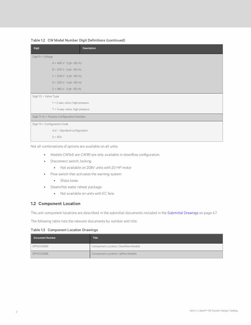
Table 1.2 CW Model Number Digit Definitions (continued)
Not all combinations of options are available on all units:
• Models CW146 are CW181 are only available in downflow configuration.
• Disconnect switch, locking
• Not available on 208V units with 20 HP motor
• Flow switch that activates the warning system
• Ships loose
• Steam/hot water reheat package
• Not available on units with EC fans
1.2 Component Location
The unit component locations are described in the submittal documents included in the Submittal Drawings on page 47.
The following table lists the relevant documents by number and title.
Document Number Title
DPN002869 Component Location, Downflow Models
DPN002868 Component Location, Upflow Models
Table 1.3 Component Location Drawings
Vertiv | Liebert® CW System Design Catalog2

1.3 Blower Configurations
Figure 1.1 Downflow Blower Configurations, Front and Rear Supply with EC Fans
Figure 1.2 Downflow Blower Configurations, Bottom and Under Floor Supply with EC Fans
NOTE: Under floor supply air EC fans requires a minimum height of 24-in.
Liebert® CW System Design Catalog 3

Figure 1.3 Upflow Blower Configurations with EC Fans in a Plenum
NOTE: In upflow units with EC fans in the plenum, supply air exits the front or rear only. Figure 1.3 above representsthe possible options.
Figure 1.4 Upflow Blower Configurations, Front Return with Forward Curved Blowers
Vertiv | Liebert® CW System Design Catalog4

Figure 1.5 Upflow Blower Configurations, Rear Return with Forward Curved Blowers
Liebert® CW System Design Catalog 5

Vertiv | Liebert® CW System Design Catalog6
This page intentionally left blank
2 SYSTEM DATA
2.1 Capacity and Performance Data
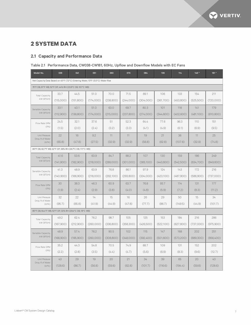
Model No. 038 041 051 060 076 084 106 114 146 * 181 *
Net Capacity Data Based on 45°F (7.2°C) Entering Water, 10°F (5.5°C) Water Rise
75°F DB, 61°F WB, 52°F DP, 44% RH (23.9°C DB, 16.1°C WB)
Total Capacity,
kW (BTUH)
33.7
(115,000)
44.5
(151,800)
51.0
(174,000)
70.0
(238,800)
71.5
(244,000)
89.1
(304,000)
106
(361,700)
133
(453,800)
154
(525,500)
211
(720,000)
Sensible Capacity,
kW (BTUH)
33.1
(112,900)
40.1
(136,800)
51.0
(174,000)
63.0
(215,000)
69.7
(237,800)
80.3
(274,000)
101
(344,600)
118
(402,600)
141
(481,100)
179
(610,800)
Flow Rate GPM
(lPs)
24.5
(1.5)
32.1
(2.0)
37.6
(2.4)
51
(3.2)
52.3
(3.3)
64.4
(4.1)
77.6
(4.9)
96.3
(6.1)
110
(6.9)
151
(9.5)
Unit Pressure
Drop, ft of Water
(kPA)
22
(65.8)
16
(47.8)
9.2
(27.5)
11
(32.9)
11
(32.9)
19
(56.8)
21
(62.8)
36
(107.6)
11
(32.9)
25
(74.8)
80°F DB, 62.7°F WB, 52°F DP, 38% RH (26.7°C DB, 17.1°C WB)
Total Capacity,
kW (BTUH)
41.6
(141,900)
53.6
(182,900)
63.9
(218,000)
84.7
(289,000)
88.2
(301,000)
107
(365,100)
130
(443,600)
159
(542,500)
186
(634,700)
249
(849,600)
Sensible Capacity,
kW (BTUH)
41.3
(140,900)
48.9
(166,900)
63.9
(218,000)
76.8
(262,100)
86.1
(293,800)
97.9
(334,000)
124
(423,100)
143
(487,900)
172
(586,900)
216
(737,000)
Flow Rate GPM
(lPs)
30
(1.9)
38.3
(2.4)
46.3
(2.9)
60.9
(3.8)
63.7
(4.0)
76.8
(4.8)
93.7
(5.9)
114
(7.2)
131
(8.3)
177
(11.2)
Unit Pressure
Drop, ft of Water
(kPA)
32
(95.7)
22
(65.8)
14
(41.9)
15
(44.9)
16
(47.8)
26
(77.7)
29
(86.7)
50
(149.5)
15
(44.9)
34
(101.7)
85°F DB, 64.4°F WB, 52°F DP, 32% RH (29.4°C DB, 18°C WB)
Total Capacity,
kW (BTUH)
49.2
(167,900)
62.4
(212,900)
76.2
(260,000)
98.7
(336,800)
105
(358,300)
125
(426,500)
153
(522,100)
184
(627,800)
216
(737,000)
286
(975,900)
Sensible Capacity,
kW (BTUH)
48.9
(166,900)
57.4
(195,900)
76.2
(260,000)
90.5
(308,800)
102
(348,000)
115
(392,400)
147
(501,600)
168
(573,200)
202
(689,300)
251
(856,400)
Flow Rate GPM
(lPs)
35.2
(2.2)
44.3
(2.8)
54.8
(3.5)
70.5
(4.4)
74.9
(4.7)
88.7
(5.6)
109
(6.9)
131
(8.3)
152
(9.6)
202
(12.7)
Unit Pressure
Drop, ft of Water
(kPA)
43
(128.6)
29
(86.7)
19
(56.8)
20
(59.8)
21
(62.8)
34
(101.7)
39
(116.6)
65
(194.4)
20
(59.8)
43
(128.6)
Table 2.1 Performance Data, CW038-CW181, 60Hz, Upflow and Downflow Models with EC Fans
Liebert® CW System Design Catalog 7

Model No. 038 041 051 060 076 084 106 114 146 * 181 *
Net Capacity Data with 50°F Entering and 62°F Leaving Fresh Water
75°F DB, 61°F WB, 52°F DP, 44% RH (23.9°C DB, 16.1°C WB)
Total Capacity,
kW (BTUH)
22.1
(75,400)
29.9
(102,000)
31.6
(107,800)
46.6
(159,000)
47.2
(161,100)
60.1
(205,100)
71.2
(242,900)
90
(307,100)
105
(358,300)
142
(484,500)
Sensible Capacity,
kW (BTUH)
22.1
(75,400)
29.9
(102,000)
31.6
(107,800)
46.6
(159,000)
47.2
(161,100)
60.1
(205,100)
71.2
(242,900)
90
(307,100)
105
(358,300)
142
(484,500)
Flow Rate GPM
(lPs)
13.9
(0.9)
18.6
(1.2)
20.4
(1.3)
29.3
(1.8)
29.8
(1.9)
37.3
(2.3)
44.8
(2.8)
56.1
(3.5)
63.6
(4)
86.6
(5.5)
Unit Pressure
Drop, ft of Water
(kPA)
7.1
(21.2)
5.9
(17.6)
2.9
(8.7)3.9 (11.7) 3.9 (11.7) 6.8 (20.3) 7.4 (22.1) 13 (38.9) 4.0 (12) 9.0 (26.9)
80°F DB, 62.7°F WB, 52°F DP, 38% RH (26.7°C DB, 17.1°C WB)
Total Capacity,
kW (BTUH)
30.8
(105,100)
39.3
(134,100)
46.6
(159,000)
61.8
(210,900)
64.8
(221,100)
78.5
(267,900)
95.5
(325,900)
116
(395,800)
137
(467,500)
180
(614,200)
Sensible Capacity,
kW (BTUH)
30.8
(105,100)
39.3
(134,100)
46.6
(159,000)
61.8
(210,900)
64.8
(221,100)
78.5
(267,900)
95.5
(325,900)
116
(395,800)
137
(467,500)
180
(614,200)
Flow Rate GPM
(lPs)
18.8
(1.2)
23.9
(1.5)
28.8
(1.8)
37.8
(2.4)
39.9
(2.5)
47.8
(3)
58.6
(3.7)
71.1
(4.5)
82.2
(5.2)
108
(6.8)
Unit Pressure
Drop, ft of Water
(kPA)
13
(38.9)
9.3
(27.8)
5.5
(16.4)
6.1
(18.2)
6.5
(19.4)
11
(32.9)
12
(35.9)
20
(59.8)
6.3
(18.8)
13
(38.9)
85°F DB, 64.4°F WB, 52°F DP, 32% RH (29.4°C DB, 18°C WB)
Total Capacity,
kW (BTUH)
39.0
(133,100)
48.1
(164,100)
59.8
(204,000)
75.9
(259,000)
81.7
(278,800)
96.1
(327,900)
119
(406,000)
142
(484,500)
169
(576,700)
216
(737,000)
Sensible Capacity,
kW (BTUH)
39.0
(133,100)
48.1
(164,100)
59.8
(204,000)
75.9
(259,000)
81.7
(278,800)
96.1
(327,900)
119
(406,000)
142
(484,500)
169
(576,700)
216
(737,000)
Flow Rate GPM
(lPs)
23.4
(1.5)
28.9
(1.8)
36.3
(2.3)
45.9
(2.9)
49.4
(3.1)
57.8
(3.6)
71.9
(4.5)
85.6
(5.4)
99.8
(6.3)
129
(8.1)
Unit Pressure
Drop, ft of Water
(kPA)
19
(56.8)
13
(38.9)
8.5
(25.4)
8.7
(26)
9.7
(29)
15
(44.9)
18
(53.8)
29
(86.7)
9.1
(27.2)
19
(56.8)
* Models CW146 and CW181 available only in downflow.
The net capacity data has fan motor heat factored in for all ratings. Capacity data is factory certified to be within 5% tolerance. Data rated with standardfilter.
Table 2.1 Performance Data, CW038-CW181, 60Hz, Upflow and Downflow Models with EC Fans (continued)
Vertiv | Liebert® CW System Design Catalog8

Model No. 038 041 051 060 076 084 106 114
Net Capacity Data with 45°F Entering and 55°F Leaving Fresh Water
75°F DB, 61°F WB, 52°F DP, 44% RH (23.9°C DB, 16.1°C WB)
Total Capacity, kW (BTUH)29.6
(101,000)
40.4
(137,900)
48.1
(164,100)
65.9
(224,900)
65.6
(223,800)
83.8
(285,900)
98.4
(335,800)
122
(416,300)
Sensible Capacity, kW (BTUH)29.6
(101,000)
36.6
(124,900)
48.1
(164,100)
59.8
(204,000)
64.8
(221,100)
75.9
(259,000)
93.8
(320,100)
109
(371,900)
Flow Rate GPM (lPs)22.9
(1.4)
30.4
(1.9)
36.1
(2.3)
48.3
(3.0)
49.2
(3.1)
61.6
(3.9)
74.3
(4.7)
90.4
(5.7)
Unit Pressure Drop, ft of Water (kPA)19
(56.8)
15
(44.9)
8.5
(25.4)
9.8
(29.3)
9.8
(29.3)
17
(50.8)
19
(56.8)
32
(95.7)
80°F DB, 62.7°F WB, 52°F DP, 38% RH (26.7°C DB, 17.1°C WB)
Total Capacity, kW (BTUH)37.2
(126,900)
49.2
(167,900)
60.7
(207,100)
80.0
(273,000)
81.7
(278,800)
101
(344,600)
122
(416,300)
147
(501,600)
Sensible Capacity, kW (BTUH)37.2
(126,900)
45.1
(153,900)
60.7
(207,100)
73.2
(249,800)
80.6
(275,000)
92.9
(317,000)
116
(395,800)
133
(453,800)
Flow Rate GPM (lPs)28.1
(1.8)
36.4
(2.3)
44.6
(2.8)
57.9
(3.6)
60.1
(3.8)
73.7
(4.6)
90
(5.7)
107
(6.7)
Unit Pressure Drop, ft of Water (kPA)28
(83.7)
20
(59.8)
13
(38.9)
14
(41.9)
14
(41.9)
24
(71.8)
27
(80.7)
45
(134.6)
85°F DB, 64.4°F WB, 52°F DP, 32% RH (29.4°C DB, 18°C WB)
Total Capacity, kW (BTUH)44.8
(152,900)
57.7
(196,900)
73.0
(249,100)
93.5
(319,000)
97.3
(332,000)
118
(402,600)
144
(491,300)
171
(583,500)
Sensible Capacity, kW (BTUH)44.8
(152,900)
53.3
(181,900)
73.0
(249,100)
86.1
(293,800)
96.4
(328,900)
110
(375,300)
139
(474,300)
157
(535,700)
Flow Rate GPM (lPs)33.2
(2.1)
42.1
(2.7)
52.9
(3.3)
67.1
(4.2)
70.8
(4.5)
85.3
(5.4)
105
(6.6)
124
(7.8)
Unit Pressure Drop, ft of Water (kPA)39
(116.6)
27
(80.7)
18
(53.8)
18
(53.8)
19
(56.8)
31
(92.7)
36
(107.6)
58
(173.4)
Table 2.2 Performance Data, CW038-CW114, 60Hz, Upflow Models with Forward Curved Blowers
Liebert® CW System Design Catalog 9

Model No. 038 041 051 060 076 084 106 114
Net Capacity Data with 50°F Entering and 62°F Leaving Fresh Water
75°F DB, 61°F WB, 52°F DP, 44% RH (23.9°C DB, 16.1°C WB)
Total Capacity, kW (BTUH)18.8
(64,100)
26.7
(91,100)
28.1
(95,900)
43.7
(149,100)
42.5
(145,000)
55.7
(190,100)
64.5
(220,100)
81.7
(278,800)
Sensible Capacity, kW (BTUH)18.8
(64,100)
26.7
(91,100)
28.1
(95,900)
43.7
(149,100)
42.5
(145,000)
55.7
(190,100)
64.5
(220,100)
81.7
(278,800)
Flow Rate GPM (lPs)12.9
(0.8)
17.6
(1.1)
18.7
(1.2)
27.7
(1.7)
28
(1.8)
35.6
(2.2)
42.7
(2.7)
52.6
(3.3)
Unit Pressure Drop, ft of Water (kPA)6.2
(18.5)
5.3
(15.8)
2.5
(7.5)
3.5
(10.5)
3.4
(10.2)
6.2
(18.5)
6.8
(20.3)
12
(35.9)
80°F DB, 62.7°F WB, 52°F DP, 38% RH (26.7°C DB, 17.1°C WB)
Unit Pressure Drop, ft of Water (kPA)27.1
(92,500)
35.7
(121,800)
43.7
(149,100)
58.0
(197,900)
59.8
(204,000)
73.8
(251,800)
88.2
(301,000)
107
(365,100)
Sensible Capacity, kW (BTUH)27.1
(92,500)
35.7
(121,800)
43.7
(149,100)
58.0
(197,900)
59.8
(204,000)
73.8
(251,800)
88.2
(301,000)
107
(365,100)
Flow Rate GPM (lPs)17.6
(1.1)
22.6
(1.4)
27.5
(1.7)
35.9
(2.3)
37.8
(2.4)
45.8
(2.9)
56.2
(3.5)
66.9
(4.2)
Unit Pressure Drop, ft of Water (kPA)11
(32.9)
8.5
(25.4)
5.0
(15.0)
5.6
(16.7)
5.9
(17.6)
9.8
(29.3)
11
(32.9)
18
(53.8)
85°F DB, 64.4°F WB, 52°F DP, 32% RH (29.4°C DB, 18°C WB)
Total Capacity, kW (BTUH)34.9
(119,100)
44.2
(150,800)
56.5
(192,800)
71.8
(245,000)
75.9
(259,000)
91.1
(310,800)
111
(378,700)
131
(447,000)
Sensible Capacity, kW (BTUH)34.9
(119,100)
44.2
(150,800)
56.5
(192,800)
71.8
(245,000)
75.9
(259,000)
91.1
(310,800)
111
(378,700)
131
(447,000)
Flow Rate GPM (lPs)22.1
(1.4)
27.5
(1.7)
34.9
(2.2)
43.7
(2.8)
47.0
(3.0)
55.6
(3.5)
69.2
(4.4)
80.7
(5.1)
Unit Pressure Drop, ft of Water (kPA)17
(50.8)
12
(35.9)
7.9
(23.6)
8.0
(23.9)
8.8
(26.3)
14
(41.9)
16
(47.8)
26
(77.7)
The net capacity data has fan motor heat factored in for all ratings. Capacity data is factory certified to be within 5% tolerance. Data rated with standardfilter.
Table 2.2 Performance Data, CW038-CW114, 60Hz, Upflow Models with Forward Curved Blowers (continued)
Vertiv | Liebert® CW System Design Catalog10

Model No. 106 114 148 181
Net Capacity Data with 50°F Entering and 64°F Leaving Fresh Water
80°F DB, 62.7°F WB, 52°F DP, 38% RH (26.7°C DB, 17.1°C WB)
Total Capacity, kW (BTUH)88.2
(301,000)
111
(378,700)
129
(440,200)
172
(586,900)
Sensible Capacity, kW (BTUH)88.2
(301,000)
111
(378,700)
129
(440,200)
172
(586,900)
Flow Rate GPM (lPs)46.7
(2.9)
58
(3.7)
66.2
(4.2)
89.4
(5.6)
Unit Pressure Drop, ft of Water (kPA)7.9
(23.6)
14
(41.9)
4.3
(12.9)
9.5
(28.4)
85°F DB, 64.4°F WB, 52°F DP, 32% RH (29.4°C DB, 18°C WB)
Total Capacity, kW (BTUH)112
(382,200)
137
(467,500)
161
(549,400)
210
(716,500)
Sensible Capacity, kW (BTUH)112
(382,200)
137
(467,500)
161
(549,400)
210
(716,500)
Flow Rate GPM (lPs)58.4
(3.7)
70.8
(4.5)
81.8
(5.2)
108
(6.8)
Unit Pressure Drop, ft of Water (kPA)12
(35.9)
20
(59.8)
6.3
(18.8)
13
(38.9)
90°F DB, 66.1°F WB, 52°F DP, 27% RH (32.2°C DB, 18.9°C WB)
Total Capacity, kW (BTUH)136
(464,100)
162
(552,800)
191
(651,700)
246
(839,400)
Sensible Capacity, kW (BTUH)136
(464,100)
162
(552,800)
191
(651,700)
246
(839,400)
Flow Rate GPM (lPs)69.7
(4.4)
83
(5.2)
96.8
(6.1)
125
(7.9)
Unit Pressure Drop, ft of Water (kPA)17
(50.8)
27
(80.7)
8.5
(25.4)
17
(50.8)
Table 2.3 Performance Data for Select Units with EC Fans, High Delta T Conditions
Liebert® CW System Design Catalog 11
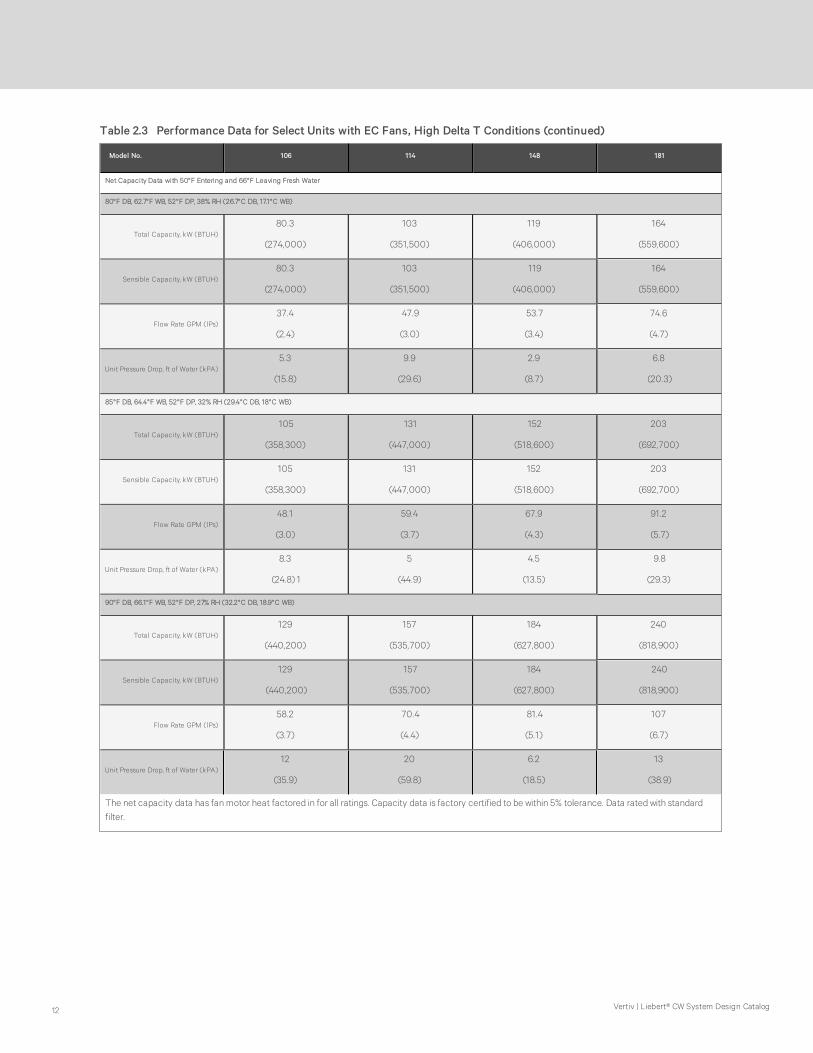
Model No. 106 114 148 181
Net Capacity Data with 50°F Entering and 66°F Leaving Fresh Water
80°F DB, 62.7°F WB, 52°F DP, 38% RH (26.7°C DB, 17.1°C WB)
Total Capacity, kW (BTUH)80.3
(274,000)
103
(351,500)
119
(406,000)
164
(559,600)
Sensible Capacity, kW (BTUH)80.3
(274,000)
103
(351,500)
119
(406,000)
164
(559,600)
Flow Rate GPM (lPs)37.4
(2.4)
47.9
(3.0)
53.7
(3.4)
74.6
(4.7)
Unit Pressure Drop, ft of Water (kPA)5.3
(15.8)
9.9
(29.6)
2.9
(8.7)
6.8
(20.3)
85°F DB, 64.4°F WB, 52°F DP, 32% RH (29.4°C DB, 18°C WB)
Total Capacity, kW (BTUH)105
(358,300)
131
(447,000)
152
(518,600)
203
(692,700)
Sensible Capacity, kW (BTUH)105
(358,300)
131
(447,000)
152
(518,600)
203
(692,700)
Flow Rate GPM (lPs)48.1
(3.0)
59.4
(3.7)
67.9
(4.3)
91.2
(5.7)
Unit Pressure Drop, ft of Water (kPA)8.3
(24.8) 1
5
(44.9)
4.5
(13.5)
9.8
(29.3)
90°F DB, 66.1°F WB, 52°F DP, 27% RH (32.2°C DB, 18.9°C WB)
Total Capacity, kW (BTUH)129
(440,200)
157
(535,700)
184
(627,800)
240
(818,900)
Sensible Capacity, kW (BTUH)129
(440,200)
157
(535,700)
184
(627,800)
240
(818,900)
Flow Rate GPM (lPs)58.2
(3.7)
70.4
(4.4)
81.4
(5.1)
107
(6.7)
Unit Pressure Drop, ft of Water (kPA)12
(35.9)
20
(59.8)
6.2
(18.5)
13
(38.9)
The net capacity data has fan motor heat factored in for all ratings. Capacity data is factory certified to be within 5% tolerance. Data rated with standardfilter.
Table 2.3 Performance Data for Select Units with EC Fans, High Delta T Conditions (continued)
Vertiv | Liebert® CW System Design Catalog12

External StaticPressure
0.2" 0.4" 0.6" 0.8" 1.0" 1.2" 1.4"
ModelRated Airflow
CFM (l/s)Motor Size, hp
0385850
(2761)5 5 5 — — —
0415750
(2714)5 — — — — — —
0519150
(4318)7.5 7.5 — — — — —
0608900
(4200)7.5 7.5 — — — — —
07612100
(5711)10 15 15 15 15 — —
08411650
(5498)10 15 15 15 15 — —
10617100
(8070)15 15 15 15 15 — —
11416500
(7787)15 15 15 15 — — —
* Delivered airflow is less than rated airflow
The net capacity data has fan motor heat factored in for all ratings. Capacity data is factory-certified to be within 5% tolerance. Data rated with standardfilter.
Table 2.4 Motor Size Required to Deliver Rated Airflow, Models with Forward Curved Blowers
Liebert® CW System Design Catalog 13

External StaticPressure
0.2" 0.4" 0.6" 0.8" 1.0" 1.2" 1.4"
ModelRated Airflow
CFM (l/s)Airflow, CFM (l/s)
0385850
(2761)
5850
(2761)
5850
(2761)
5850
(2761)
5750
(2714)
5600
(2643)
5450
(2572)
5350
(2525)
0415750
(2714)
5750
(2714)
5750
(2714)
5600
(2643)
5450
(2572)
5350
(2525)— —
0519150
(4318)
9150
(4318)
9150
(4318)
9100
(4295)
8900
(4200)
8700
(4106)
8550
(4035)
8350
(3941)
0608900
(4200)
8900
(4200)
8900
(4200)
8750
(4130)
8550
(4035)
8400
(3964)
8200
(3870)
8050
(3799)
07612100
(5711)
12100
(5711)
12100
(5711)
12100
(5711)
12100
(5711)
12100
(5711)
11600
(5475)
11000
(5191)
08411650
(5498)
11650
(5498)
11650
(5498)
11650
(5498)
11650 (
5498)
11650
(5498)
11400
(5380)NA
10617100
(8070)
17100
(8070)
17100
(8070)
17100 (
8070)
17100
(8070)
17100
(8070)
16400
(7740)
16100
(7598)
11416500
(7787)
16500
(7787)
16500
(7787)
16500
(7787)
16500
(7787)16100 — —
Table 2.5 Maximum Airflow with Maximum Motor Size at Listed Static
Pressure, Models with Forward Curved Blowers
2.2 Physical Data
Model Sizes 038 041 051 060 076 084
FAN SECTION
Some options or combinations of options may result in reduced airflow. Consult your sales representative for recommendations.
Fan Data - EC Fans - Available in Upflow and Downflow Orientations
Nominal Air Volume, CFM (CMH)6,050
(10,285)
5,950
(10,115)
9,200
(15,640)
9,200
(15,640)
12,400
(21,080)
11,900
(20,230)
Fan Motor, Maximum hp (kW), Downflow, each4.0
(3.0)
4.0
(3.0)
3.6 (2.7)
for 208/230 V
3.4 (2.5)
for 380 to 460V,
60 Hz/50 Hz
3.6(2.7)
for 208/230 V
3.4(2.5)
for 380 to 460V,
60 Hz/50 Hz
4.0
(3.0)
4.0
(3.0)
Fan Motor, Max hp (kW),
Upflow, each4.0 (3.0) 4.0 (3.0) 4.0 (3.0) 4.0 (3.0) 4.0 (3.0) 4.0 (3.0)
Standard Ext Static Pressure, inches of water (PA) 0.2 (50) 0.2 (50) 0.2 (50) 0.2 (50) 0.2 (50) 0.2 (50)
Number of Fans 1 1 2 2 2 2
Fan Data - Forward-curved Blowers - Variable Pitch, Two-Belt Drive Package - Available in Upflow Configurations
Table 2.6 Physical Data, CW038 - CW084, 60Hz Models
Vertiv | Liebert® CW System Design Catalog14

Model Sizes 038 041 051 060 076 084
Nominal Air Volume,
CFM (CMH)
5,850
(9,940)
5,750
(9,770)
9,150
(15,550)
8,900
(15,120)
12,100
(20,560)
11,650
(19,790)
Fan Motor, Maximum hp (kW), each 5.0 (3.7) 7.5 (5.6) 10.0 (7.5)
Standard Ext Static Pressure, inches of water (PA) 0.2 (50) 0.2 (50) 0.2 (50) 0.2 (50) 0.2 (50) 0.2 (50)
Number of Fans 1 1 2 2 2 2
CHILLED WATER COIL
Face Area, ft2 (m2) 11.7 (1.1) 18.5 (1.7) 25.0 (2.3)
Number of Rows 4 6 4 6 4 6
Face Velocity, EC Fans, FPM (m/s)519
(2.63)
510
(2.59)
503
(2.55)
503
(2.55)
496
(2.51)
476
(2.41)
Chilled Water Valves (Standard valves, Maximum design water pressure 400 PSI [2758 kPA].
Valve Actuator, Sensors, and Body Modulating Valve Actuator with Proportional Sensors and either 2-Way or 3-Way Valve Body
Valve Size, in. 1-1/4 1-1/2 1-1/2 2 2 2
MBV 2-way Valve Cv 10.0 29.0 29.0 46.0 46.0 46.0
MBV 2-Way Valve (Opt) Close-off Pressure, PSI (kPA) 200 (1379) 200 (1379) 200 (1379) 200 (1379) 200 (1379) 200 (1379)
MBV 3-way Valve Cv 11.7 29.2 29.2 46.8 46.8 46.8
MBV 3-Way Valve bypass Cv 7.4 18.7 18.7 29.2 29.2 29.2
REHEAT SECTION
Electric Reheat - Three Stage, Fin/Tube
Capacity, BTU/HR (kW)51,195
(15)
68,260
(20)
83,325
(25)
102,390
(30)
Steam Reheat: 218°F (103.3°C) Steam, 75°F (23.9°C)
EAT
Modulating 2-way, 150 PSI (1034.3 kPa) max operating pressure. Not applicable to units with EC fans. Unit CFM reduced by 300 with
standard motor (142 l/s)
Capacity, BTU/HR (kW)85,800
(25.1)
85,800
(25.1)
93,400
(27.4)
144,500
(42.4)
163,200
(47.8)
163,200
(47.8)
Hot Water Reheat @ 180°F (82.2°C) EWT & 75°F
(23.8°C) EAT
Modulating 2-way, 150 PSI (1034.3 kPa) max operating pressure. Not applicable to units with EC fans. Unit CFM reduced by 300 with
standard motor (142 l/s)
Capacity, BTU/HR (kW)49,500
(14.5)
49,500
(14.5)
89,900
(26.3)
89,900
(26.3)
125,200
(36.7)
125,200
(36.7)
Flow Rate, GPM (l/s) 5 (0.31) 5 (0.31) 8 (0.50) 8 (0.50) 8 (0.50) 8 (0.50)
Pressure Drop, PSI (kPA) 3.5 (24.1) 1.6 (11.0) 1.6 (11.0)
HUMIDIFIER SECTION
Infrared Humidifier
Capacity, lb/hr (kg/h) 11 (5.0) 11 (5.0) 17.4 (7.9) 17.4 (7.9) 22.1 (10) 22.1 (10)
kW 4.8 4.8 6.4 6.4 9.6 9.6
FILTER SECTION
Disposable Type - Nominal Size and Quantities, MERV8 and MERV11 (option)
Downflow Models
Nominal Size, in 18 x 24
Quantity 4 4 6 6 8 8
Upflow Models (Front Return)
Table 2.6 Physical Data, CW038 - CW084, 60Hz Models (continued)
Liebert® CW System Design Catalog 15

Model Sizes 038 041 051 060 076 084
Nominal Size, in 24 x 24
Quantity 2 2 3 3 4 4
Upflow Models (Bottom and Rear Return)
Nominal Size, in 18 x 24
Quantity 4 4 6 6 8 8
CONNECTION SIZES
Chilled Water, OD Copper 1-3/8 1-5/8 1-5/8 2-1/8 2-1/8 2-1/8
Infrared Humidifier, OD Copper 1/4 1/4 1/4 1/4 1/4 1/4
Condensate Drain, FPT 3/4 3/4 3/4 3/4 3/4 3/4
Steam Reheat, MPT, FC Blower only 1/2 1/2 1/2 3/4 3/4 3/4
Hot Water Reheat, OD Copper, FC Blower only 5/8 5/8 7/8 7/8 7/8 7/8
Table 2.6 Physical Data, CW038 - CW084, 60Hz Models (continued)
Model Sizes 106 114 146 181
FAN SECTION
Some options or combinations of options may result in reduced airflow. Consult your Vertiv representative for recommendations.
Fan Data - EC Fans - CW106 & CW114 are available in Upflow and Downflow Orientations. CW146 to CW181 are available in Downflow only.
Nominal Air Volume, CFM (CMH)17,300
(29,410)
17,300
(29,410)
21,000
(35,700)
24,000
(40,800)
Fan Motor, Maximum hp (kW), Downflow, each 4.0 (3.0) 4.0 (3.0) 3.7 (2.8) 4.9 (3.7)
Fan Motor, Maximum hp (kW), Upflow, each 4.0 (3.0) 4.0 (3.0) — —
Standard Ext Static Pressure, inches of water (PA) 0.2 (50)
Number of Fans 3 3 3 3
Fan Data -Forward-curved Blowers - Variable Pitch, Two-Belt Drive Package - CW106 and CW114 are available in Upflow Orientations. CW146 to CW181 are available with EC Fans in downflow
orientation only.
Nominal Air Volume, CFM (CMH)17,100
(29,050)
16,500
(28,030)— —
Fan Motor, Maximum hp (kW), each 3.0 (2.2) 5.0 (3.7) — —
Standard Ext Static Pressure, inches of water (PA) 0.2 (50) — —
Number of Fans 3 3 — —
CHILLED WATER COIL
Face Area, ft2 (m2) 36.3 (3.4) 56.3 (5.3)
Number of Rows 4 6 4 6
Face Velocity, EC Fans, FPM (m/s) 476 (1.34) 373 (1.89) 427 (2.16)
Chilled Water Valves (Standard valves, Maximum design water pressure 400 PSI [2758 kPA].
Valve Actuator, Sensors, & BodyModulating Valve Actuator with Proportional Sensors and
either 2-Way or 3-Way Valve Body
Valve Size, in. 2 2 2 (qty. 2) 2 (qty. 2)
MBV 2-way Valve Cv 46.0 46.0 46.0 46.0
Table 2.7 Physical Data, CW106 - CW181, 60Hz Models
Vertiv | Liebert® CW System Design Catalog16
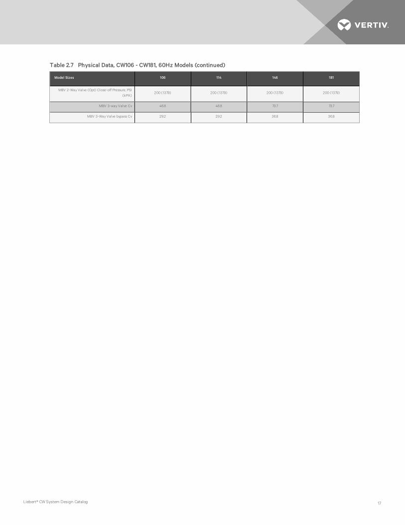
Model Sizes 106 114 146 181
MBV 2-Way Valve (Opt) Close-off Pressure, PSI
(kPA)200 (1379) 200 (1379) 200 (1379) 200 (1379)
MBV 3-way Valve Cv 46.8 46.8 73.7 73.7
MBV 3-Way Valve bypass Cv 29.2 29.2 36.8 36.8
Table 2.7 Physical Data, CW106 - CW181, 60Hz Models (continued)
Liebert® CW System Design Catalog 17

Model Sizes 106 114 146 181
REHEAT SECTION
Electric Reheat - Three-Stage, Fin Tube
Capacity, BTU/HR (kW) 102,390 (30) 102,390 (30)
Steam Reheat: 218°F (103.3°C) Steam, 75°F (23.9)
EAT
Modulating 2-way, 150 PSI (1034.3 kPa) maximum operating pressure.
Not applicable to units with EC fans.
Unit CFM reduced by 300 with standard motor (142 l/s)
Capacity, BTU/HR (kW) 84,100 (24.6) 85,800 (25.1) — —
Hot Water Reheat @ 180°F (82.2°C) EWT 75°F
(23.8°C) EAT
Modulating 2-way, 150 PSI (1034.3 kPa) maximum operating pressure.
Not applicable to units with EC fans.
Unit CFM reduced by 300 with standard motor (142 l/s)
Capacity, BTU/HR (kW) 133,700 (39.2) — —
Flow Rate, GPM (l/s) 8 (0.50) — —
Pressure Drop, PSI (kPA) 1.6 (11.0) — —
HUMIDIFIER SECTION
Infrared Humidifier Note (50Hz Models are 22.1 lb/h (10.0 kg/h); 9.6 kW)
Capacity, lb/hr (kg/h) 22.1 (10) 22.1 (10) 22.1 (10)
kW 9.6 9.6 9.6 9.6
FILTER SECTION
Disposable Type - Nominal Size and Quantities, MERV8 and MERV11 (option)
Downflow Models
Nominal Size, in 24 x 31 21.5 x 24
Quantity 5 5 10 10
Upflow Models (Front Return)
Nominal Size, in 18 x 24 N/A N/A
Quantity 10 10 N/A N/A
Upflow Models (Bottom & Rear Return)
Nominal Size, in 18 x 24 N/A N/A
Quantity 10 10 N/A N/A
CONNECTION SIZES
Chilled Water, OD Copper2-1/8” (Downflow models)
2-5/8" (Upflow models)2-5/8” 3-1/8” 3-1/8”
Infrared Humidifier, OD Copper 1/4” 1/4” 1/4” 1/4”
Condensate Drain, FPT 1-1/4” 1-1/4” 1-1/4” 1-1/4”
Steam Reheat, MPT 3/4” 3/4” N/A N/A
Hot Water Reheat, OD Copper 7/8” 7/8” N/A N/A
Table 2.7 Physical Data, CW106 - CW181, 60Hz Models (continued)
Vertiv | Liebert® CW System Design Catalog18

3 ELECTRICAL POWER REQUIREMENTS
The tables on the following pages list the electrical data.
Models Volts
Reheat/Humidifier No Reheat/Humidifier
208 230 380 460 575 208 230 380 460 575
CW038
FLA 64.1 59.4 31.6 29.5 25.7 22.5 20.3 11.0 9.8 10.6
WSA 80.1 74.3 39.5 36.9 32.1 28.1 25.4 13.8 12.3 13.3
OPD 90 80 40 40 35 30 30 15 15 15
CW041
FLA 64.1 59.4 31.6 29.5 25.7 22.5 20.3 11.0 9.8 10.6
WSA 80.1 74.3 39.5 36.9 32.1 28.1 25.4 13.8 12.3 13.3
OPD 90 80 40 40 35 30 30 15 15 15
CW051
Downflow
FLA 98.7 91.3 48.2 45.5 — 43.2 38.8 20.8 19.3 —
WSA 123.4 114.1 60.3 56.9 — 54.0 48.5 26.0 24.1 —
OPD 125 125 70 60 — 60 45 30 25 —
CW051
Upflow
FLA 100.5 93.1 50.0 47.1 40.0 45.0 40.6 22.6 20.9 19.9
WSA 125.6 116.4 62.5 58.9 50.0 56.3 50.8 28.3 26.1 24.9
OPD 150 125 70 60 60 50 50 25 30 25
CW060
Downflow
FLA 112.6 104.3 55.1 52.0 — 43.2 38.8 20.8 19.3 —
WSA 140.8 130.4 68.9 65.0 — 54.0 48.5 26.0 24.1 —
OPD 150 150 70 70 — 60 45 30 25 —
CW060
Upflow
FLA 114.4 106.1 56.9 53.6 45.0 45.0 40.6 22.6 20.9 19.9
WSA 143.0 132.6 71.1 67.0 56.3 56.3 50.8 28.3 26.1 24.9
OPD 150 150 80 70 60 50 50 25 30 25
CW076
FLA 124.1 119.2 63.1 58.7 48.1 45.0 40.6 22.0 19.6 18.0
WSA 155.1 149.0 78.9 73.4 60.1 56.3 50.8 27.5 24.5 22.5
OPD 175 150 80 80 70 50 50 25 25 25
CW084
FLA 124.1 119.2 63.1 58.7 48.1 45.0 40.6 22.0 19.6 18.0
WSA 155.1 149.0 78.9 73.4 60.1 56.3 50.8 27.5 24.5 22.5
OPD 175 150 80 80 70 50 50 25 25 25
CW106
FLA 133.3 128.4 68.0 62.7 51.3 54.2 49.8 26.9 23.6 21.2
WSA 166.6 160.5 85.0 78.4 64.1 67.8 62.3 33.6 29.5 26.5
OPD 175 175 90 80 70 70 70 35 30 30
Table 3.1 Electrical Data by Reheat Option with Humidifier and Without Condensate Pump, 60 Hz Systems with EC
Fans
Liebert® CW System Design Catalog 19
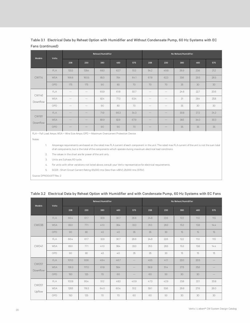
Models Volts
Reheat/Humidifier No Reheat/Humidifier
208 230 380 460 575 208 230 380 460 575
CW114
FLA 133.3 128.4 68.0 62.7 51.3 54.2 49.8 26.9 23.6 21.2
WSA 166.6 160.5 85.0 78.4 64.1 67.8 62.3 33.6 29.5 26.5
OPD 175 175 90 80 70 70 70 35 30 30
CW146
Downflow
FLA — — 65.9 61.8 50.7 — — 24.8 22.7 20.6
WSA — — 82.4 77.3 63.4 — — 31 28.4 25.8
OPD — — 90 80 70 — — 35 30 30
CW181
Downflow
FLA — — 71.9 66.3 54.3 — — 30.8 27.2 24.2
WSA — — 89.9 82.9 67.9 — — 38.5 34.0 30.3
OPD — — 90 90 70 — — 35 35 35
FLA = Full Load Amps; WSA = Wire Size Amps; OPD = Maximum Overcurrent Protection Device
Notes:
1. Amperage requirements are based on the rated max FLA current of each component in the unit. The rated max FLA current of the unit is not the sum total
of all components, but is the total of the components which operate during maximum electrical load conditions.
2. The values in the chart are for power of the unit only.
3. Units are 3 phase, 60 cycle.
4. For units with other variations not listed above, consult your Vertiv representative for electrical requirements.
5. SCCR - Short Circuit Current Rating 65,000 rms (less than 480V), 25,000 rms (575V).
Source: DPN004977 Rev. 2
Table 3.1 Electrical Data by Reheat Option with Humidifier and Without Condensate Pump, 60 Hz Systems with EC
Fans (continued)
Models Volts
Reheat/Humidifier No Reheat/Humidifier
208 230 380 460 575 208 230 380 460 575
CW038
FLA 66.4 61.7 32.8 30.7 26.6 24.8 22.6 12.2 11.0 11.5
WSA 83.0 77.1 41.0 38.4 33.3 31.0 28.3 15.3 13.8 14.4
OPD 90 80 45 40 35 35 30 15 15 15
CW041
FLA 66.4 61.7 32.8 30.7 26.6 24.8 22.6 12.2 11.0 11.5
WSA 83.0 77.1 41.0 38.4 33.3 31.0 28.3 15.3 13.8 14.4
OPD 90 80 45 40 35 35 30 15 15 15
CW051
Downflow
FLA 101.0 93.6 49.4 46.7 — 45.5 41.1 22.0 20.5 —
WSA 126.3 117.0 61.8 58.4 — 56.9 51.4 27.5 25.6 —
OPD 150 125 70 60 — 60 50 30 30 —
CW051
Upflow
FLA 102.8 95.4 51.2 48.3 40.9 47.3 42.9 23.8 22.1 20.8
WSA 128.5 119.3 64.0 60.4 51.2 59.1 53.6 29.8 27.6 26.0
OPD 150 125 70 70 60 60 50 30 30 30
Table 3.2 Electrical Data by Reheat Option with Humidifier and with Condensate Pump, 60 Hz Systems with EC Fans
Vertiv | Liebert® CW System Design Catalog20

Models Volts
Reheat/Humidifier No Reheat/Humidifier
208 230 380 460 575 208 230 380 460 575
CW060
Downflow
FLA 114.9 106.6 56.3 53.2 — 45.5 41.1 22.0 20.5 —
WSA 143.6 133.3 70.4 66.5 — 56.9 51.4 27.5 25.6 —
OPD 150 150 80 70 — 60 50 30 30 —
CW060
Upflow
FLA 116.7 108.4 58.1 54.8 45.9 47.3 42.9 23.8 22.1 20.8
WSA 145.9 135.5 72.6 68.5 57.4 59.1 53.6 29.8 27.6 26.0
OPD 150 150 80 70 60 60 50 30 30 30
CW076
FLA 126.4 121.5 64.3 59.9 49.0 47.3 42.9 23.2 20.8 18.9
WSA 158.0 151.9 80.4 74.9 61.3 59.1 53.6 29.0 26.0 23.7
OPD 175 175 90 80 70 60 50 30 30 25
CW084
FLA 126.4 121.5 64.3 59.9 49.0 47.3 42.9 23.2 20.8 18.9
WSA 158.0 151.9 80.4 74.9 61.3 59.1 53.6 29.0 26.0 23.7
OPD 175 175 90 80 70 60 50 30 30 25
CW106
FLA 135.6 130.7 69.2 63.9 52.2 56.5 52.1 28.1 24.8 22.1
WSA 169.5 163.4 86.5 79.9 65.3 70.6 65.1 35.1 31.0 27.7
OPD 175 175 90 80 70 80 70 40 35 30
CW114
FLA 135.6 130.7 69.2 63.9 52.2 56.5 52.1 28.1 24.8 22.1
WSA 169.5 163.4 86.5 79.9 65.3 70.6 65.1 35.1 31.0 27.7
OPD 175 175 90 80 70 80 70 40 35 30
CW146
Downflow
FLA — — 67.1 63.0 51.6 — — 26 23.9 21.5
WSA — — 83.9 78.8 64.5 — — 32.5 29.9 26.9
OPD — — 90 80 70 — — 35 30 30
CW181
Downflow
FLA — — 73.1 67.5 55.2 — — 32.0 28.4 25.1
WSA — — 91.4 84.4 69.0 — — 40 35.5 31.4
OPD — — 100 90 70 — — 45 40 35
FLA = Full Load Amps; WSA = Wire Size Amps; OPD = Maximum Overcurrent Protection Device
Notes:
1. Amperage requirements are based on the rated max FLA current of each component in the unit. The rated max FLA current of the unit is not the sum total
of all components, but is the total of the components which operate during maximum electrical load conditions.
2. The values in the chart are for power of the unit only.
3. Units are 3 phase, 60 cycle.
4. For units with other variations not listed above, consult your Vertiv representative for electrical requirements.
5. SCCR - Short Circuit Current Rating 65,000 rms (less than 480V), 25,000 rms (575V).
Source: DPN004977 Rev. 2
Table 3.2 Electrical Data by Reheat Option with Humidifier and with Condensate Pump, 60 Hz Systems with EC Fans
(continued)
Liebert® CW System Design Catalog 21

Models Volts
Reheat/No Humidifier No Reheat/No Humidifier
208 230 380 460 575 208 230 380 460 575
CW038
FLA 50.8 48.3 25.5 23.7 18.3 9.2 9.2 4.9 4.0 3.2
WSA 63.5 60.4 31.9 29.6 22.9 11.5 11.5 6.1 5.0 4.0
OPD 70 70 35 30 25 20 20 15 15 15
CW041
FLA 50.8 48.3 25.5 23.7 18.3 9.2 9.2 4.9 4.0 3.2
WSA 63.5 60.4 31.9 29.6 22.9 11.5 11.5 6.1 5.0 4.0
OPD 70 70 35 30 25 20 20 15 15 15
CW051
Downflow
FLA 72.1 69.1 35.4 32.6 — 16.6 16.6 8.0 6.4 —
WSA 90.1 86.4 44.3 40.8 — 18.7 18.7 9.0 7.2 —
OPD 100 90 45 45 — 25 25 15 15 —
CW051
Upflow
FLA 73.9 70.9 37.2 34.2 26.5 18.4 18.4 9.8 8.0 6.4
WSA 92.4 88.6 46.5 42.8 33.1 20.7 20.7 11.0 9.0 7.2
OPD 100 90 50 45 35 25 25 15 15 15
CW060
Downflow
FLA 86.0 82.1 42.3 39.1 — 16.6 16.6 8.0 6.4 —
WSA 107.5 102.6 52.9 48.9 — 18.7 18.7 9.0 7.2 —
OPD 110 110 60 50 — 25 25 15 15 —
CW060
Upflow
FLA 87.8 83.9 44.1 40.7 31.5 18.4 18.4 9.8 8.0 6.4
WSA 109.8 104.9 55.1 50.9 39.4 20.7 20.7 11.0 9.0 7.2
OPD 110 110 60 60 40 25 25 15 15 15
CW076
FLA 97.5 97.0 50.9 47.1 36.5 18.4 18.4 9.8 8.0 6.4
WSA 121.9 121.3 63.6 58.9 45.6 20.7 20.7 11.0 9.0 7.2
OPD 125 125 70 60 50 25 25 15 15 15
CW084
FLA 97.5 97.0 50.9 47.1 36.5 18.4 18.4 9.8 8.0 6.4
WSA 121.9 121.3 63.6 58.9 45.6 20.7 20.7 11.0 9.0 7.2
OPD 125 125 70 60 50 25 25 15 15 15
CW106
FLA 106.7 106.2 55.8 51.1 39.7 27.6 27.6 14.7 12.0 9.6
WSA 133.4 132.8 69.8 63.9 49.6 29.9 29.9 15.9 13.0 10.4
OPD 150 150 70 70 50 35 35 20 15 15
CW114
FLA 106.7 106.2 55.8 51.1 39.7 27.6 27.6 14.7 12.0 9.6
WSA 133.4 132.8 69.8 63.9 49.6 29.9 29.9 15.9 13.0 10.4
OPD 150 150 70 70 50 35 35 20 15 15
Table 3.3 Electrical Data by Reheat Option without Humidifier and without Condensate Pump, 60 Hz Systems with
EC Fans
Vertiv | Liebert® CW System Design Catalog22

Models Volts
Reheat/No Humidifier No Reheat/No Humidifier
208 230 380 460 575 208 230 380 460 575
CW146
Downflow
FLA — — 53.7 50.2 39.1 — — 12.6 11.1 9.0
WSA — — 67.1 62.8 48.9 — — 13.7 12.0 9.8
OPD — — 70 70 50 — — 15 15 15
CW181
Downflow
FLA — — 59.7 54.7 42.7 — — 18.6 15.6 12.6
WSA — — 74.6 68.4 53.4 — — 20.2 16.9 13.7
OPD — — 80 70 60 — — 25 20 15
FLA = Full Load Amps; WSA = Wire Size Amps; OPD = Maximum Overcurrent Protection Device
Notes:
1. Amperage requirements are based on the rated max FLA current of each component in the unit. The rated max FLA current of the unit is not the sum
total of all components, but is the total of the components which operate during maximum electrical load conditions.
2. The values in the chart are for power of the unit only.
3. Units are 3 phase, 60 cycle.
4. For units with other variations not listed above, consult your Vertiv representative for electrical requirements.
5. SCCR - Short Circuit Current Rating 65,000 rms (less than 480V), 25,000 rms (575V).
Source: DPN004977 Rev. 2
Table 3.3 Electrical Data by Reheat Option without Humidifier and without Condensate Pump, 60 Hz Systems with
EC Fans (continued)
Models Volts
Reheat/No Humidifier No Reheat/No Humidifier
208 230 380 460 575 208 230 380 460 575
CW038
FLA 53.1 50.6 26.7 24.9 19.2 11.5 11.5 6.1 5.2 4.1
WSA 66.4 63.3 33.4 31.1 24.0 13.8 13.8 7.3 6.2 4.9
OPD 70 70 35 35 25 20 20 15 15 15
CW041
FLA 53.1 50.6 26.7 24.9 19.2 11.5 11.5 6.1 5.2 4.1
WSA 66.4 63.3 33.4 31.1 24.0 13.8 13.8 7.3 6.2 4.9
OPD 70 70 35 35 25 20 20 15 15 15
CW051
Downflow
FLA 74.4 71.4 36.6 33.8 — 18.9 18.9 9.2 7.6 —
WSA 93.0 89.3 45.8 42.3 — 21.0 21.0 10.2 8.4 —
OPD 100 90 50 45 — 25 25 15 15 —
CW051
Upflow
FLA 76.2 73.2 38.4 35.4 27.4 20.7 20.7 11.0 9.2 7.3
WSA 95.3 91.5 48.0 44.3 34.3 23.0 23.0 12.2 10.2 8.1
OPD 100 100 50 45 35 30 30 15 15 15
Table 3.4 Electrical Data by Reheat Option without Humidifier and with Condensate Pump, 60 Hz Systems with EC
Fans
Liebert® CW System Design Catalog 23

Models Volts
Reheat/No Humidifier No Reheat/No Humidifier
208 230 380 460 575 208 230 380 460 575
CW060
Downflow
FLA 88.3 84.4 43.5 40.3 — 18.9 18.9 9.2 7.6 —
WSA 110.4 105.5 54.4 50.4 — 21.0 21.0 10.2 8.4 —
OPD 125 110 60 60 — 25 25 15 15 —
CW060
Upflow
FLA 90.1 86.2 45.3 41.9 32.4 20.7 20.7 11.0 9.2 7.3
WSA 112.6 107.8 56.6 52.4 40.5 23.0 23.0 12.2 10.2 8.1
OPD 125 110 60 60 45 30 30 15 15 15
CW076
FLA 99.8 99.3 52.1 48.3 37.4 20.7 20.7 11.0 9.2 7.3
WSA 124.8 124.1 65.1 60.4 46.8 23.0 23.0 12.2 10.2 8.1
OPD 125 125 70 70 50 30 30 15 15 15
CW084
FLA 99.8 99.3 52.1 48.3 37.4 20.7 20.7 11.0 9.2 7.3
WSA 124.8 124.1 65.1 60.4 46.8 23.0 23.0 12.2 10.2 8.1
OPD 125 125 70 70 50 30 30 15 15 15
CW106
FLA 109.0 108.5 57.0 52.3 40.6 29.9 29.9 15.9 13.2 10.5
WSA 136.3 135.6 71.3 65.4 50.8 32.2 32.2 17.1 14.1 11.3
OPD 150 150 80 70 60 40 40 20 15 15
CW114
FLA 109.0 108.5 57.0 52.3 40.6 29.9 29.9 15.9 13.2 10.5
WSA 136.3 135.6 71.3 65.4 50.8 32.2 32.2 17.1 14.2 11.3
OPD 150 150 80 70 60 40 40 20 15 15
CW146
Downflow
FLA — — 54.9 51.4 40.0 — — 13.8 12.3 9.9
WSA — — 68.6 64.3 50.0 — — 14.9 13.2 10.7
OPD — — 70 70 60 — — 15 15 15
CW181
Downflow
FLA — — 60.9 55.9 43.6 — — 19.8 16.8 13.5
WSA — — 76.1 69.9 54.5 — — 21.4 18.1 13.9
OPD — — 80 70 60 — — 25 20 15
FLA = Full Load Amps; WSA = Wire Size Amps; OPD = Maximum Overcurrent Protection Device
Notes:
1. Amperage requirements are based on the rated max FLA current of each component in the unit. The rated max FLA current of the unit is not the sum
total of all components, but is the total of the components which operate during maximum electrical load conditions.
2. The values in the chart are for power of the unit only.
3. Units are 3 phase, 60 cycle.
4. For units with other variations not listed above, consult your Vertiv representative for electrical requirements.
5. SCCR - Short Circuit Current Rating 65,000 rms (less than 480V), 25,000 rms (575V).
Source: DPN004977 Rev. 2
Table 3.4 Electrical Data by Reheat Option without Humidifier and with Condensate Pump, 60 Hz Systems with EC
Fans (continued)
Vertiv | Liebert® CW System Design Catalog24

Models /
Motor HPVolts
Reheat/Humidifier No Reheat/Humidifier
208 230 380 460 575 208 230 380 460 575
CW038
3.0 HP
FLA 65.5 59.8 32.5 30.3 26.4 23.9 20.7 11.9 10.6 11.3
WSA 81.9 74.8 40.6 37.9 33.0 29.9 25.9 14.9 13.3 14.1
MFCB 90 80 45 40 35 35 30 15 15 15
CW038
5.0 HP
FLA 71.6 65.4 35.9 33.1 28.6 30.0 26.3 15.3 13.4 13.5
WSA 89.5 81.8 44.9 41.4 35.8 37.5 32.9 19.1 16.8 16.9
MFCB 90 80 45 40 35 50 45 25 20 20
CW041
3.0 HP
FLA 65.5 59.8 32.5 30.3 26.4 23.9 20.7 11.9 10.6 11.3
WSA 81.9 74.8 40.6 37.9 33.0 29.9 25.9 14.9 13.3 14.1
MFCB 90 80 45 40 35 35 30 15 15 15
CW041
5.0 HP
FLA 71.6 65.4 35.9 33.1 28.6 30.0 26.3 15.3 13.4 13.5
WSA 89.5 81.8 44.9 41.4 35.8 37.5 32.9 19.1 16.8 16.9
MFCB 90 80 45 40 35 50 45 25 20 20
CW051
5.0 HP
FLA 98.8 89.9 49.4 46.7 39.7 43.3 37.4 22 20.5 19.6
WSA 123.5 112.4 61.8 58.4 49.6 54.1 46.8 27.5 25.6 24.5
MFCB 125 125 70 60 50 60 50 30 30 25
CW051
7.5 HP
FLA 106.3 96.7 53.5 50.1 42.6 50.8 44.2 26.1 23.9 22.5
WSA 132.9 120.9 66.9 62.6 53.3 63.5 55.3 32.6 29.9 28.1
MFCB 125 110 70 60 50 80 70 40 35 30
CW060
5.0 HP
FLA 112.7 102.9 56.3 53.2 44.7 43.3 37.4 22 20.5 19.6
WSA 140.9 128.6 70.4 66.5 55.9 54.1 46.8 27.5 25.6 24.5
MFCB 150 125 80 70 60 60 50 30 30 25
CW060
7.5 HP
FLA 120.2 109.7 60.4 56.6 47.6 50.8 44.2 26.1 23.9 22.5
WSA 150.3 137.1 75.5 70.8 59.5 63.5 55.3 32.6 29.9 28.1
MFCB 150 125 70 80 60 80 70 40 35 30
CW076
7.5 HP
FLA 129.9 122.8 66.6 61.7 50.7 50.8 44.2 25.5 22.6 20.6
WSA 162.4 153.5 83.3 77.1 63.4 63.5 55.3 31.9 28.3 25.8
MFCB 175 150 90 80 70 80 70 40 35 30
CW076
10.0 HP
FLA 136.5 128.8 70.2 64.7 52.7 57.4 50.2 29.1 25.6 22.6
WSA 170.6 161.0 87.8 80.9 65.9 71.8 62.8 36.4 32.0 28.3
MFCB 175 150 90 80 60 90 80 50 40 35
Table 3.5 Electrical Data by Reheat Option with Humidifier and without Condensate Pump, 60 Hz Systems
with Forward Curved Blowers
Liebert® CW System Design Catalog 25
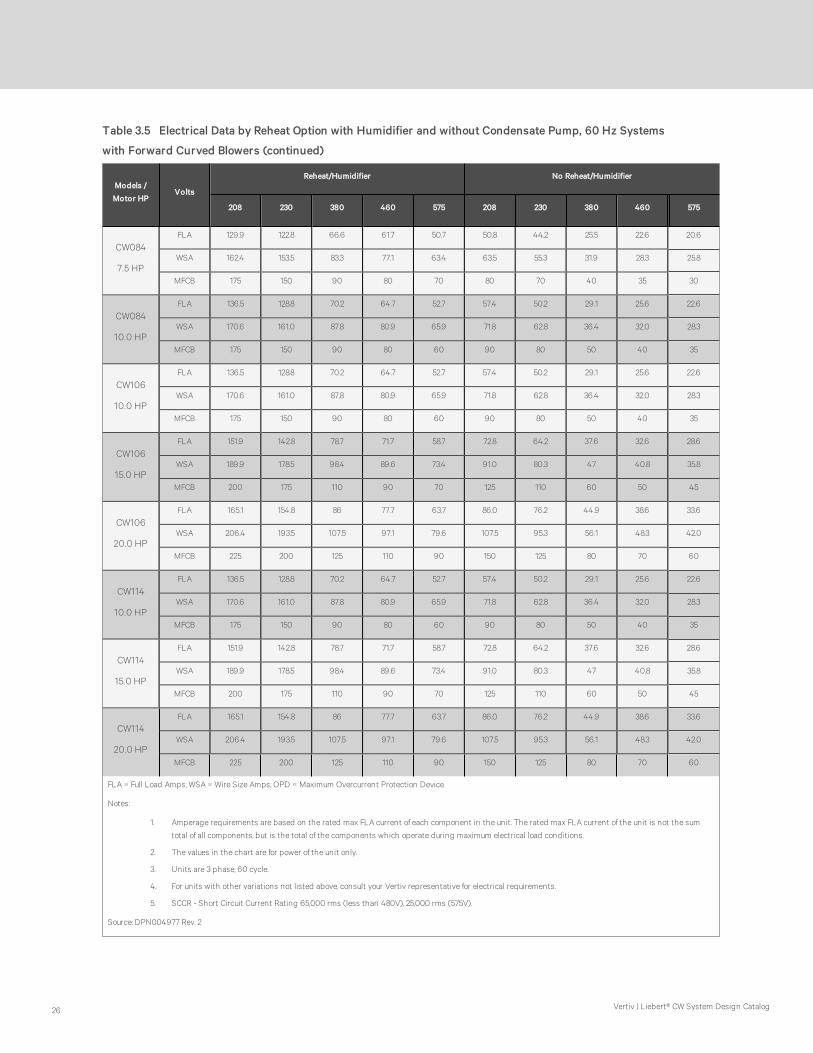
Models /
Motor HPVolts
Reheat/Humidifier No Reheat/Humidifier
208 230 380 460 575 208 230 380 460 575
CW084
7.5 HP
FLA 129.9 122.8 66.6 61.7 50.7 50.8 44.2 25.5 22.6 20.6
WSA 162.4 153.5 83.3 77.1 63.4 63.5 55.3 31.9 28.3 25.8
MFCB 175 150 90 80 70 80 70 40 35 30
CW084
10.0 HP
FLA 136.5 128.8 70.2 64.7 52.7 57.4 50.2 29.1 25.6 22.6
WSA 170.6 161.0 87.8 80.9 65.9 71.8 62.8 36.4 32.0 28.3
MFCB 175 150 90 80 60 90 80 50 40 35
CW106
10.0 HP
FLA 136.5 128.8 70.2 64.7 52.7 57.4 50.2 29.1 25.6 22.6
WSA 170.6 161.0 87.8 80.9 65.9 71.8 62.8 36.4 32.0 28.3
MFCB 175 150 90 80 60 90 80 50 40 35
CW106
15.0 HP
FLA 151.9 142.8 78.7 71.7 58.7 72.8 64.2 37.6 32.6 28.6
WSA 189.9 178.5 98.4 89.6 73.4 91.0 80.3 47 40.8 35.8
MFCB 200 175 110 90 70 125 110 60 50 45
CW106
20.0 HP
FLA 165.1 154.8 86 77.7 63.7 86.0 76.2 44.9 38.6 33.6
WSA 206.4 193.5 107.5 97.1 79.6 107.5 95.3 56.1 48.3 42.0
MFCB 225 200 125 110 90 150 125 80 70 60
CW114
10.0 HP
FLA 136.5 128.8 70.2 64.7 52.7 57.4 50.2 29.1 25.6 22.6
WSA 170.6 161.0 87.8 80.9 65.9 71.8 62.8 36.4 32.0 28.3
MFCB 175 150 90 80 60 90 80 50 40 35
CW114
15.0 HP
FLA 151.9 142.8 78.7 71.7 58.7 72.8 64.2 37.6 32.6 28.6
WSA 189.9 178.5 98.4 89.6 73.4 91.0 80.3 47 40.8 35.8
MFCB 200 175 110 90 70 125 110 60 50 45
CW114
20.0 HP
FLA 165.1 154.8 86 77.7 63.7 86.0 76.2 44.9 38.6 33.6
WSA 206.4 193.5 107.5 97.1 79.6 107.5 95.3 56.1 48.3 42.0
MFCB 225 200 125 110 90 150 125 80 70 60
FLA = Full Load Amps; WSA = Wire Size Amps; OPD = Maximum Overcurrent Protection Device
Notes:
1. Amperage requirements are based on the rated max FLA current of each component in the unit. The rated max FLA current of the unit is not the sum
total of all components, but is the total of the components which operate during maximum electrical load conditions.
2. The values in the chart are for power of the unit only.
3. Units are 3 phase, 60 cycle.
4. For units with other variations not listed above, consult your Vertiv representative for electrical requirements.
5. SCCR - Short Circuit Current Rating 65,000 rms (less than 480V), 25,000 rms (575V).
Source: DPN004977 Rev. 2
Table 3.5 Electrical Data by Reheat Option with Humidifier and without Condensate Pump, 60 Hz Systems
with Forward Curved Blowers (continued)
Vertiv | Liebert® CW System Design Catalog26
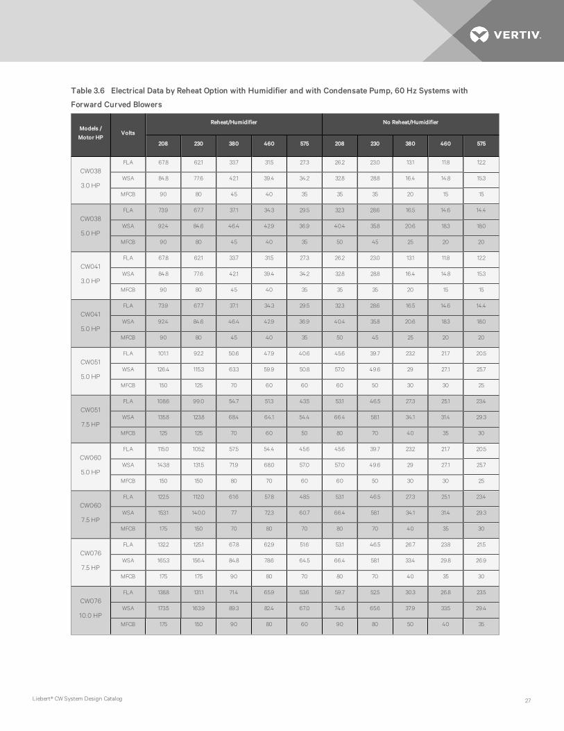
Models /
Motor HPVolts
Reheat/Humidifier No Reheat/Humidifier
208 230 380 460 575 208 230 380 460 575
CW038
3.0 HP
FLA 67.8 62.1 33.7 31.5 27.3 26.2 23.0 13.1 11.8 12.2
WSA 84.8 77.6 42.1 39.4 34.2 32.8 28.8 16.4 14.8 15.3
MFCB 90 80 45 40 35 35 35 20 15 15
CW038
5.0 HP
FLA 73.9 67.7 37.1 34.3 29.5 32.3 28.6 16.5 14.6 14.4
WSA 92.4 84.6 46.4 42.9 36.9 40.4 35.8 20.6 18.3 18.0
MFCB 90 80 45 40 35 50 45 25 20 20
CW041
3.0 HP
FLA 67.8 62.1 33.7 31.5 27.3 26.2 23.0 13.1 11.8 12.2
WSA 84.8 77.6 42.1 39.4 34.2 32.8 28.8 16.4 14.8 15.3
MFCB 90 80 45 40 35 35 35 20 15 15
CW041
5.0 HP
FLA 73.9 67.7 37.1 34.3 29.5 32.3 28.6 16.5 14.6 14.4
WSA 92.4 84.6 46.4 42.9 36.9 40.4 35.8 20.6 18.3 18.0
MFCB 90 80 45 40 35 50 45 25 20 20
CW051
5.0 HP
FLA 101.1 92.2 50.6 47.9 40.6 45.6 39.7 23.2 21.7 20.5
WSA 126.4 115.3 63.3 59.9 50.8 57.0 49.6 29 27.1 25.7
MFCB 150 125 70 60 60 60 50 30 30 25
CW051
7.5 HP
FLA 108.6 99.0 54.7 51.3 43.5 53.1 46.5 27.3 25.1 23.4
WSA 135.8 123.8 68.4 64.1 54.4 66.4 58.1 34.1 31.4 29.3
MFCB 125 125 70 60 50 80 70 40 35 30
CW060
5.0 HP
FLA 115.0 105.2 57.5 54.4 45.6 45.6 39.7 23.2 21.7 20.5
WSA 143.8 131.5 71.9 68.0 57.0 57.0 49.6 29 27.1 25.7
MFCB 150 150 80 70 60 60 50 30 30 25
CW060
7.5 HP
FLA 122.5 112.0 61.6 57.8 48.5 53.1 46.5 27.3 25.1 23.4
WSA 153.1 140.0 77 72.3 60.7 66.4 58.1 34.1 31.4 29.3
MFCB 175 150 70 80 70 80 70 40 35 30
CW076
7.5 HP
FLA 132.2 125.1 67.8 62.9 51.6 53.1 46.5 26.7 23.8 21.5
WSA 165.3 156.4 84.8 78.6 64.5 66.4 58.1 33.4 29.8 26.9
MFCB 175 175 90 80 70 80 70 40 35 30
CW076
10.0 HP
FLA 138.8 131.1 71.4 65.9 53.6 59.7 52.5 30.3 26.8 23.5
WSA 173.5 163.9 89.3 82.4 67.0 74.6 65.6 37.9 33.5 29.4
MFCB 175 150 90 80 60 90 80 50 40 35
Table 3.6 Electrical Data by Reheat Option with Humidifier and with Condensate Pump, 60 Hz Systems with
Forward Curved Blowers
Liebert® CW System Design Catalog 27

Models /
Motor HPVolts
Reheat/Humidifier No Reheat/Humidifier
208 230 380 460 575 208 230 380 460 575
CW084
7.5 HP
FLA 132.2 125.1 67.8 62.9 51.6 53.1 46.5 26.7 23.8 21.5
WSA 165.3 156.4 84.8 78.6 64.5 66.4 58.1 33.4 29.8 26.9
MFCB 175 175 90 80 70 80 70 40 35 30
CW084
10.0 HP
FLA 138.8 131.1 71.4 65.9 53.6 59.7 52.5 30.3 26.8 23.5
WSA 173.5 163.9 89.3 82.4 67.0 74.6 65.6 37.9 33.5 29.4
MFCB 175 150 90 80 60 90 80 50 40 35
CW106
10.0 HP
FLA 138.8 131.1 71.4 65.9 53.6 59.7 52.5 30.3 26.8 23.5
WSA 173.5 163.9 89.3 82.4 67.0 74.6 65.6 37.9 33.5 29.4
MFCB 175 150 90 80 60 90 80 50 40 35
CW106
15.0 HP
FLA 154.2 145.1 79.9 72.9 59.6 75.1 66.5 38.8 33.8 29.5
WSA 192.8 181.4 99.9 91.1 74.5 93.9 83.1 48.5 42.3 36.9
MFCB 200 175 110 90 80 125 110 70 60 50
CW106
20.0 HP
FLA 167.4 157.1 87.2 78.9 64.6 88.3 78.5 46.1 39.8 34.5
WSA 209.3 196.4 109 98.6 80.8 110.4 98.1 57.6 49.8 43.2
MFCB 225 200 125 110 90 150 125 80 70 60
CW114
10.0 HP
FLA 138.8 131.1 71.4 65.9 53.6 59.7 52.5 30.3 26.8 23.5
WSA 173.5 163.9 89.3 82.4 67.0 74.6 65.6 37.9 33.5 29.4
MFCB 175 150 90 80 60 90 80 50 40 35
CW114
15.0 HP
FLA 154.2 145.1 79.9 72.9 59.6 75.1 66.5 38.8 33.8 29.5
WSA 192.8 181.4 99.9 91.1 74.5 93.9 83.1 48.5 42.3 36.9
MFCB 200 175 110 90 80 125 110 70 60 50
CW114
20.0 HP
FLA 167.4 157.1 87.2 78.9 64.6 88.3 78.5 46.1 39.8 34.5
WSA 209.3 196.4 109 98.6 80.8 110.4 98.1 57.6 49.8 43.2
MFCB 225 200 125 110 90 150 125 80 70 60
FLA = Full Load Amps; WSA = Wire Size Amps; OPD = Maximum Overcurrent Protection Device
Notes:
1. Amperage requirements are based on the rated max FLA current of each component in the unit. The rated max FLA current of the unit is not the sum
total of all components, but is the total of the components which operate during maximum electrical load conditions.
2. The values in the chart are for power of the unit only.
3. Units are 3 phase, 60 cycle.
4. For units with other variations not listed above, consult your Vertiv representative for electrical requirements.
5. SCCR - Short Circuit Current Rating 65,000 rms (less than 480V), 25,000 rms (575V).
Source: DPN004977 Rev. 2
Table 3.6 Electrical Data by Reheat Option with Humidifier and with Condensate Pump, 60 Hz Systems with For-
ward Curved Blowers (continued)
Vertiv | Liebert® CW System Design Catalog28

Models /
Motor HPVolts
Reheat/No Humidifier No Reheat/No Humidifier
208 230 380 460 575 208 230 380 460 575
CW038
3.0 HP
FLA 52.2 48.7 26.4 24.5 19.0 10.6 9.6 5.8 4.8 3.9
WSA 65.3 60.9 33 30.6 23.8 13.3 12.0 7.3 6.0 4.9
MFCB 60 70 30 35 25 20 20 15 15 15
CW038
5.0 HP
FLA 58.3 54.3 29.8 27.3 21.2 16.7 15.2 9.2 7.6 6.1
WSA 72.9 67.9 37.3 34.1 26.5 20.9 19.0 11.5 9.5 7.6
MFCB 70 70 40 35 25 35 30 20 15 15
CW041
3.0 HP
FLA 52.2 48.7 26.4 24.5 19.0 10.6 9.6 5.8 4.8 3.9
WSA 65.3 60.9 33 30.6 23.8 13.3 12.0 7.3 6.0 4.9
MFCB 60 70 30 35 25 20 20 15 15 15
CW041
5.0 HP
FLA 58.3 54.3 29.8 27.3 21.2 16.7 15.2 9.2 7.6 6.1
WSA 72.9 67.9 37.3 34.1 26.5 20.9 19.0 11.5 9.5 7.6
MFCB 70 70 40 35 25 35 30 20 15 15
CW051
5.0 HP
FLA 72.2 67.7 36.6 33.8 26.2 16.7 15.2 9.2 7.6 6.1
WSA 90.3 84.6 45.8 42.3 32.8 20.9 19.0 11.5 9.5 7.6
MFCB 90 80 45 40 30 35 30 20 15 15
CW051
7.5 HP
FLA 79.7 74.5 40.7 37.2 29.1 24.2 22.0 13.3 11.0 9.0
WSA 99.6 93.1 50.9 46.5 36.4 30.3 27.5 16.6 13.8 11.3
MFCB 100 100 50 50 40 50 45 25 20 20
CW060
5.0 HP
FLA 86.1 80.7 43.5 40.3 31.2 16.7 15.2 9.2 7.6 6.1
WSA 107.6 100.9 54.4 50.4 39.0 20.9 19.0 11.5 9.5 7.6
MFCB 110 110 50 60 40 35 30 20 15 15
CW060
7.5 HP
FLA 93.6 87.5 47.6 43.7 34.1 24.2 22.0 13.3 11.0 9.0
WSA 117.0 109.4 59.5 54.6 42.6 30.3 27.5 16.6 13.8 11.3
MFCB 110 110 60 50 45 50 45 25 20 20
CW076
7.5 HP
FLA 103.3 100.6 54.4 50.1 39.1 24.2 22.0 13.3 11.0 9.0
WSA 129.1 125.8 68 62.6 48.9 30.3 27.5 16.6 13.8 11.3
MFCB 125 125 70 60 50 50 45 25 20 20
CW076
10.0 HP
FLA 109.9 106.6 58 53.1 41.1 30.8 28.0 16.9 14.0 11.0
WSA 137.4 133.3 72.5 66.4 51.4 38.5 35.0 21.1 17.5 13.8
MFCB 125 125 70 70 50 60 60 35 30 20
Table 3.7 Electrical data by Reheat Option without Humidifier and without Condensate Pump, 60 Hz Systems with
Forward Curved Blowers
Liebert® CW System Design Catalog 29

Models /
Motor HPVolts
Reheat/No Humidifier No Reheat/No Humidifier
208 230 380 460 575 208 230 380 460 575
CW084
7.5 HP
FLA 103.3 100.6 54.4 50.1 39.1 24.2 22.0 13.3 11.0 9.0
WSA 129.1 125.8 68 62.6 48.9 30.3 27.5 16.6 13.8 11.3
MFCB 125 125 70 60 50 50 45 25 20 20
CW084
10.0 HP
FLA 109.9 106.6 58.0 53.1 41.1 30.8 28.0 16.9 14.0 11.0
WSA 137.4 133.3 72.5 66.4 51.4 38.5 35.0 21.1 17.5 13.8
MFCB 125 125 70 70 50 60 60 35 30 20
CW106
10.0 HP
FLA 109.9 106.6 58 53.1 41.1 30.8 28.0 16.9 14.0 11.0
WSA 137.4 133.3 72.5 66.4 51.4 38.5 35.0 21.1 17.5 13.8
MFCB 125 125 70 70 50 60 60 35 30 20
CW106
15.0 HP
FLA 125.3 120.6 66.5 60.1 47.1 46.2 42.0 25.4 21.0 17.0
WSA 156.6 150.8 83.1 75.1 58.9 57.8 52.5 31.8 26.3 21.3
MFCB 175 150 90 80 60 100 90 50 45 35
CW106
20.0 HP
FLA 138.5 132.6 73.8 66.1 52.1 59.4 54.0 32.7 27.0 22.0
WSA 173.1 165.8 92.3 82.6 65.1 74.3 67.5 40.9 33.8 27.5
MFCB 200 200 110 90 70 125 110 70 60 45
CW114
10.0 HP
FLA 109.9 106.6 58 53.1 41.1 30.8 28.0 16.9 14.0 11.0
WSA 137.4 133.3 72.5 66.4 51.4 38.5 35.0 21.1 17.5 13.8
MFCB 125 125 70 70 50 60 60 35 30 20
CW114
15.0 HP
FLA 125.3 120.6 66.5 60.1 47.1 46.2 42.0 25.4 21.0 17.0
WSA 156.6 150.8 83.1 75.1 58.9 57.8 52.5 31.8 26.3 21.3
MFCB 175 150 90 80 60 100 90 50 45 35
CW114
20.0 HP
FLA 138.5 132.6 73.8 66.1 52.1 59.4 54.0 32.7 27.0 22.0
WSA 173.1 165.8 92.3 82.6 65.1 74.3 67.5 40.9 33.8 27.5
MFCB 200 200 110 90 70 125 110 70 60 45
FLA = Full Load Amps; WSA = Wire Size Amps; OPD = Maximum Overcurrent Protection Device
Notes:
1. Amperage requirements are based on the rated max FLA current of each component in the unit. The rated max FLA current of the unit is not the sum total
of all components, but is the total of the components which operate during maximum electrical load conditions.
2. The values in the chart are for power of the unit only.
3. Units are 3 phase, 60 cycle.
4. For units with other variations not listed above, consult your Vertiv representative for electrical requirements.
5. SCCR - Short Circuit Current Rating 65,000 rms (less than 480V), 25,000 rms (575V).
Source: DPN004977 Rev. 2
Table 3.7 Electrical data by Reheat Option without Humidifier and without Condensate Pump, 60 Hz Systems with
Forward Curved Blowers (continued)
Vertiv | Liebert® CW System Design Catalog30

Models /
Motor HPVolts
Reheat/No Humidifier No Reheat/No Humidifier
208 230 380 460 575 208 230 380 460 575
CW038
3.0 HP
FLA 54.5 51.0 27.6 25.7 19.9 12.9 11.9 7.0 6.0 4.8
WSA 68.1 63.8 34.5 32.1 24.9 15.6 14.3 8.5 7.2 5.8
MFCB 70 70 35 35 25 25 20 15 15 15
CW038
5.0 HP
FLA 60.6 56.6 31 28.5 22.1 19.0 17.5 10.4 8.8 7.0
WSA 75.8 70.8 38.8 35.6 27.7 23.2 21.3 12.7 10.7 8.5
MFCB 80 70 40 35 25 35 35 20 15 15
CW041
3.0 HP
FLA 54.5 51.0 27.6 25.7 19.9 12.9 11.9 7 6.0 4.8
WSA 68.1 63.8 34.5 32.1 24.9 15.6 14.3 8.5 7.2 5.8
MFCB 70 70 35 35 25 25 20 15 15 15
CW041
5.0 HP
FLA 60.6 56.6 31.0 28.5 22.1 19.0 17.5 10.4 8.8 7.0
WSA 75.8 70.8 38.8 35.6 27.7 23.2 21.3 12.7 10.7 8.5
MFCB 80 70 40 35 25 35 35 20 15 15
CW051
5.0 HP
FLA 74.5 70.0 37.8 35.0 27.1 19.0 17.5 10.4 8.8 7.0
WSA 93.1 87.5 47.3 43.8 33.9 23.2 21.3 12.7 10.7 8.5
MFCB 90 80 45 40 35 35 35 20 15 15
CW051
7.5 HP
FLA 82.0 76.8 41.9 38.4 30.0 26.5 24.3 14.5 12.2 9.9
WSA 102.5 96.0 52.4 48.0 37.5 32.6 29.8 17.8 15.0 12.2
MFCB 110 100 50 50 40 50 50 30 25 20
CW060
5.0 HP
FLA 88.4 83.0 44.7 41.5 32.1 19.0 17.5 10.4 8.8 7.0
WSA 110.5 103.8 55.9 51.9 40.2 23.2 21.3 12.7 10.7 8.5
MFCB 125 110 50 60 45 35 35 20 15 15
CW060
7.5 HP
FLA 95.9 89.8 48.8 44.9 35.0 26.5 24.3 14.5 12.2 9.9
WSA 119.9 112.3 61 56.1 43.8 32.6 29.8 17.8 15.0 12.2
MFCB 125 110 60 50 45 50 50 30 25 20
CW076
7.5 HP
FLA 105.6 102.9 55.6 51.3 40.0 26.5 24.3 14.5 12.2 9.9
WSA 132.0 128.6 69.5 64.1 50.0 32.6 29.8 17.8 15.0 12.2
MFCB 125 125 70 60 50 50 50 30 25 20
CW076
10.0 HP
FLA 112.2 108.9 59.2 54.3 42.0 33.1 30.3 18.1 15.2 11.9
WSA 140.3 136.1 74 67.9 52.5 40.8 37.3 22.3 18.7 14.7
MFCB 150 125 80 70 50 70 60 35 30 25
Table 3.8 Electrical Data by Reheat Option without Humidifier with Condensate Pump, 60 Hz Systems with Forward
Curved Blowers
Liebert® CW System Design Catalog 31

Models /
Motor HPVolts
Reheat/No Humidifier No Reheat/No Humidifier
208 230 380 460 575 208 230 380 460 575
CW084
7.5 HP
FLA 105.6 102.9 55.6 51.3 40.0 26.5 24.3 14.5 12.2 9.9
WSA 132.0 128.6 69.5 64.1 50.0 32.6 29.8 17.8 15.0 12.2
MFCB 125 125 70 60 50 50 50 30 25 20
CW084
10.0 HP
FLA 112.2 108.9 59.2 54.3 42.0 33.1 30.3 18.1 15.2 11.9
WSA 140.3 136.1 74 67.9 52.5 40.8 37.3 22.3 18.7 14.7
MFCB 150 125 80 70 50 70 60 35 30 25
CW106
10.0 HP
FLA 112.2 108.9 59.2 54.3 42.0 33.1 30.3 18.1 15.2 11.9
WSA 140.3 136.1 74 67.9 52.5 40.8 37.3 22.3 18.7 14.7
MFCB 150 125 80 70 50 70 60 35 30 25
CW106
15.0 HP
FLA 127.6 122.9 67.7 61.3 48.0 48.5 44.3 26.6 22.2 17.9
WSA 159.5 153.6 84.6 76.6 60.0 60.1 54.8 33 27.5 22.2
MFCB 175 175 90 80 60 100 90 50 45 35
CW106
20.0 HP
FLA 140.8 134.9 75 67.3 53.0 61.7 56.3 33.9 28.2 22.9
WSA 176.0 168.6 93.8 84.1 66.3 76.6 69.8 42.1 35.0 28.4
MFCB 200 200 110 100 80 125 110 70 60 50
CW114
10.0 HP
FLA 112.2 108.9 59.2 54.3 42.0 33.1 30.3 18.1 15.2 11.9
WSA 140.3 136.1 74 67.9 52.5 40.8 37.3 22.3 18.7 14.7
MFCB 150 125 80 70 50 70 60 35 30 25
CW114
15.0 HP
FLA 127.6 122.9 67.7 61.3 48.0 48.5 44.3 26.6 22.2 17.9
WSA 159.5 153.6 84.6 76.6 60.0 60.1 54.8 33 27.5 22.2
MFCB 175 175 90 80 60 100 90 50 45 35
CW114
20.0 HP
FLA 140.8 134.9 75.0 67.3 53.0 61.7 56.3 33.9 28.2 22.9
WSA 176.0 168.6 93.8 84.1 66.3 76.6 69.8 42.1 35.0 28.4
MFCB 200 200 110 100 80 125 110 70 60 50
FLA = Full Load Amps; WSA = Wire Size Amps; OPD = Maximum Overcurrent Protection Device
Notes:
1. Amperage requirements are based on the rated max FLA current of each component in the unit. The rated max FLA current of the unit is not the sum total
of all components, but is the total of the components which operate during maximum electrical load conditions.
2. The values in the chart are for power of the unit only.
3. Units are 3 phase, 60 cycle.
4. For units with other variations not listed above, consult your Vertiv representative for electrical requirements.
5. SCCR - Short Circuit Current Rating 65,000 rms (less than 480V), 25,000 rms (575V).
Source: DPN004977 Rev. 2
Table 3.8 Electrical Data by Reheat Option without Humidifier with Condensate Pump, 60 Hz Systems with Forward
Curved Blowers (continued)
Vertiv | Liebert® CW System Design Catalog32

HP
Voltage
208 230 460 575
FLA LRA FLA LRA FLA LRA FLA LRA
2.0 7.5 55.0 6.8 50.0 3.4 25.0 2.7 20.0
3.0 10.6 71.0 9.6 64.0 4.8 32.0 3.9 25.6
5.0 16.7 102.0 15.2 92.0 7.6 46.0 6.1 36.8
7.5 24.2 140.0 22.0 127.0 11.0 63.5 9.0 50.8
10.0 30.8 179.0 28.0 162.0 14.0 81.0 11.0 64.8
15.0 46.2 257.0 42.0 232.0 21.0 116.0 17.0 93.0
20.0 59.4 321.0 54.0 290.0 27.0 145.0 22.0 116.0
Note: Refer to General Data Section for standard fan-motor size on units.
Source: DPN004977 Rev. 2
Table 3.9 Indoor Evaporator Forward Curved Fan Motor Electrical Requirements, 60 Hz Systems
Liebert® CW System Design Catalog 33

3.1 Electrical Field Connections
Three phase electrical service is required for all models. Electrical service must conform to national and local electricalcodes.
The electrical connections are described in the submittal documents included in the Submittal Drawings on page 47.
The following table lists the relevant documents by number and title.
Document Number Title
Downflow Units
DPN004548 Electrical Field Connections, Downflow CW038 to CW084
DPN004549 Electrical Field Connections, Downflow, CW106, and CW114
DPN004550 Electrical Field Connections, Downflow, CW146 and CW181
Upflow Units
DPN003200 High-voltage Connections, Upflow, CW038 to CW084
DPN004552 Low-voltage and Ethernet Connections, Upflow, CW038 to CW084
DPN003202 High Voltage Connections, Upflow, CW106, and CW114
DPN004551 Low Voltage and Ethernet Connection, Upflow CW106, and CW114
Unit to Unit Networking
DPN004351 Liebert® iCOM Unit to Unit Network Connections
Table 3.10 Electrical Field Connection Drawings
Vertiv | Liebert® CW System Design Catalog34

4 PLANNING GUIDELINES
4.1 Location Considerations
For a downflow unit, the unit can sit on an accessible, elevated flooring system. It may be necessary to furnish additionalpedestal support below the unit to ensure maximum structural support. A separate floor stand for the unit may be used assupport, independent of the elevated floor and installed prior to the flooring system.
For downflow and upflow units, provide approximately 34 in. (864 mm) service clearance on the left, right and in front of theunit whenever possible. The minimum space required for service is 18 in. (457 mm) on the left end, 18 in. (457 mm) on theright end and 24 in. (610 mm) in front of the unit. This space is necessary to permit routine maintenance, such as replacingfilters and adjusting the fan speed. On downflow and upflow CW106 and CW114 models, left and right end minimumclearances are 0 in. (0 mm) except for rear return.
Avoid installing units in an alcove or at the extreme end of a room that has a high aspect ratio (long narrow room). Alsoavoid installing units too close together. This tends to reduce the effectiveness of the air distribution as compared to unitslocated 30 to 40 ft (9 to 12 mm) apart.
4.2 Shipping Dimensions and Unit Weights
Model Domestic Packed, in. (mm) Export Packed, in. (mm)
038, 041 64 X 45 X 85 (1625.6 X 1143 X 2159) 64.5 X 45 X 85.5 (1683.3 X 1143 X 2171.1)
051, 060 97 X 45 X 85 (2463.8 X 1143 X 2159) 97.5 X 45 X 85.5 (2476.5 X 1143 X 2171.1)
076, 084 120 X 45 X 85 (3048 X 1143 X 2159) 120.5 X 45 X85.5 (3060.7 X 2476.5 X 2171.1)
106, 114 143 X45 X 85 (3632.2 X 1143 X 2159) 143.5 X 45 X 85.5 (3632.2 X 2476.4 X 2171.1)
146, 181 136 X 54 X 85 (3454.4 X 1143 X 2159) 136.5 X 54.5 X 85.5 (3467.1 X 2576.4 X 2171.1)
Table 4.1 Shipping Dimensions
Model Domestic Packaging, lb. (kg) Export Packaging, lb. (kg)
038 840 (381) 1065 (483)
041 890 (404) 1115 (506)
051 1135 (515) 1360 (617)
060 1200 (544) 1425 (646)
076 1380 (625) 1630 (739)
084 1480 (671) 1730 (785)
106 1950 (885) 2225 (1,009)
114 2090 (949) 2365 (1,073)
146 2900 (1,314) 3200 (1,450)
181 2900 (1,314) 3200 (1,450)
Table 4.2 Shipping Weights
Liebert® CW System Design Catalog 35
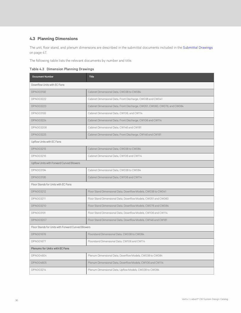
4.3 Planning Dimensions
The unit, floor stand, and plenum dimensions are described in the submittal documents included in the Submittal Drawingson page 47.
The following table lists the relevant documents by number and title.
Document Number Title
Downflow Units with EC Fans
DPN003192 Cabinet Dimensional Data, CW038 to CW084
DPN003222 Cabinet Dimensional Data, Front Discharge, CW038 and CW041
DPN003223 Cabinet Dimensional Data, Front Discharge, CW051, CW060, CW076, and CW084
DPN003193 Cabinet Dimensional Data, CW106, and CW114
DPN003224 Cabinet Dimensional Data, Front Discharge, CW106 and CW114
DPN003208 Cabinet Dimensional Data, CW146 and CW181
DPN003225 Cabinet Dimensional Data, Front Discharge, CW146 and CW181
Upflow Units with EC Fans
DPN003215 Cabinet Dimensional Data, CW038 to CW084
DPN003216 Cabinet Dimensional Data, CW106 and CW114
Upflow Units with Forward Curved Blowers
DPN003194 Cabinet Dimensional Data, CW038 to CW084
DPN003195 Cabinet Dimensional Data, CW106 and CW114
Floor Stands for Units with EC Fans
DPN003212 Floor Stand Dimensional Data, Downflow Models, CW038 to CW041
DPN003211 Floor Stand Dimensional Data, Downflow Models, CW051 and CW060
DPN003210 Floor Stand Dimensional Data, Downflow Models, CW076 and CW084
DPN003191 Floor Stand Dimensional Data, Downflow Models, CW106 and CW114
DPN003207 Floor Stand Dimensional Data, Downflow Models, CW146 and CW181
Floor Stands for Units with Forward Curved Blowers
DPN001676 Floorstand Dimensional Data, CW038 to CW084
DPN001677 Floorstand Dimensional Data, CW106 and CW114
Plenums for Units with EC Fans
DPN004604 Plenum Dimensional Data, Downflow Models, CW038 to CW084
DPN004605 Plenum Dimensional Data, Downflow Models, CW106 and CW114
DPN003214 Plenum Dimensional Data, Upflow Models, CW038 to CW084
Table 4.3 Dimension Planning Drawings
Vertiv | Liebert® CW System Design Catalog36

Document Number Title
DPN003213 Plenum Dimensional Data, Upflow Models, CW106 and CW114
Plenums for Units with Forward Curved Blowers
DPN003204 Plenum Dimensional Data, Upflow Models, CW038 to CW084
DPN003205 Plenum Dimensional Data, Upflow Models, CW106 and CW114
Table 4.3 Dimension Planning Drawings (continued)
Liebert® CW System Design Catalog 37

Vertiv | Liebert® CW System Design Catalog38
This page intentionally left blank

5 PIPING
Field installed piping must be installed in accordance with local code.
The following pipe connections are required:
• A drain line from the evaporator coil drain pan.
• A water supply line to the optional humidifier (if applicable).
• Connections to the building chilled water source.
The pipe connection locations, piping general arrangement and schematics are described in the submittal documentsincluded in the Submittal Drawings on page 47.
The following tables list the relevant documents by number and title.
Document Number Title
DPN004561 Piping Schematic, Downflow, CW038 to CW114
DPN004138 Piping Schematic, Downflow, CW146 and CW181
DPN004562 Piping Schematic, Upflow, CW038 to CW114
Table 5.1 Piping General Arrangement Drawings
Document Number Title
Downflow Units with EC Fans
DPN002036 Connection Locations, CW038 and CW041
DPN002035 Connection Locations, CW051 and 050
DPN002034 Connection Locations, CW075 to CW084
DPN001628 Connection Locations, CW106 and CW114
DPN001693 Connection Locations, CW146 and CW181
Upflow Units with Forward Curved Blowers
DPN001668 Connection Locations, CW038 to CW084
DPN001669 Connection Locations, CW106 and CW114
Table 5.2 Piping Connection Drawings
Liebert® CW System Design Catalog 39

Vertiv | Liebert® CW System Design Catalog40
This page intentionally left blank

APPENDICES
Appendix A: Technical Support and Contacts
A.1 Technical Support/Service in the United States
Vertiv™ Group Corporation
24x7 dispatch of technicians for all products.
1-800-543-2378
Liebert® Thermal Management Products
1-800-543-2778
Liebert® Channel Products
1-800-222-5877
Liebert® AC and DC Power Products
1-800-543-2378
A.2 Locations
United States
Vertiv Headquarters
1050 Dearborn Drive
Columbus, OH, 43085, USA
Europe
Via Leonardo Da Vinci 8 Zona Industriale Tognana
35028 Piove Di Sacco (PD) Italy
Asia
7/F, Dah Sing Financial Centre
3108 Gloucester Road
Wanchai, Hong Kong
41

Vertiv | Liebert® CW System Design Catalog42
This page intentionally left blank

Appendix B: Optional Configuration for Liebert CW Seismic Application
Electrical wiring, conduit, and/or other connections to the equipment is the responsibility of others. Data andrecommendations are supplied in the Submittal Drawings on page 47, and in the unit installation supplement for seismicinstallation.
The following table lists the relevant documents by number and title.
Document Number Title
DPN003209 Seismic Application Assumptions and Requirements
Table B.1 Seismic Application Drawings
Liebert® CW System Design Catalog 43

Vertiv | Liebert® CW System Design Catalog44
This page intentionally left blank

Appendix C: Optional Liebert® Air Economizer™ for Liebert® CW
The Liebert® Air Economizer is an option for Liebert® CW™ chilled water downflow units and Liebert® DS™ downflow units.The Liebert® Air Economizer uses cool outdoor air in mild climates to condition indoor spaces. It is functional only oncooling units with Liebert® Liebert® iCOM™ controls that are factory-wired and configured to accommodate the Liebert®Air Economizer.
The Liebert® Air Economizer is supplied with electrical wiring for connection to the cooling unit, outdoor air sensors, returnair sensors and a temperature-and-humidity-sensing unit the appropriate drawings included in the Submittal Drawings onpage 47.
The following table lists the relevant documents by number and title.
Document Number Title
DPN001333 Air Economizer Ducting
DPN003226 Planning Dimensions for CW106 to CW114 Downflow Models
DPN003227 Planning Dimensions for CW038 to CW084 Downflow Models
DPN001449 Air Economizer Field Connections
Table C.1 Liebert® Air Economizer Drawings
Special firmware is loaded into the primary cooling unit at the factory to permit the primary cooling unit to control theLiebert® Air Economizer.
NOTE: When upgrading the firmware for the primary cooling unit, either a Liebert® DS downflow unit or Liebert® CWdownflow unit, ensure that the new firmware includes the Liebert® Air Economizer controls. If in doubt, contact yoursales representative.
C.1 Customer Supplied Equipment and Ductwork
Installation and operation requires outside air entry duct work with louvers, screening and filtration to prevent intrusion ofprecipitation, particulates, vermin and unauthorized entry, DPN001333 included in the Submittal Drawings on page 47.
Proper installation also requires a customer provided powered relief air discharge to rid the structure of the outside airdrawn in for cooling. The relief-air discharge must be equivalent to the airflow of the total of all cooling systems equippedwith the Air Economizer.
A flange is provided to attach the Air Economizer to the outdoor air duct. See DPN003226 and DPN003227 in theSubmittal Drawings on page 47.
Liebert® CW System Design Catalog 45

Vertiv | Liebert® CW System Design Catalog46
This page intentionally left blank

Appendix D: Submittal Drawings
Document Number Title
Component Location
DPN002869 Component Location, Downflow Models
DPN002868 Component Location, Upflow Models
Planning Dimensions--Downflow Units with EC Fans
DPN003192 Cabinet Dimensional Data, CW038to CW084
DPN003222 Cabinet Dimensional Data, Front Discharge, CW038 and CW041
DPN003223 Cabinet Dimensional Data, Front Discharge, CW051, CW060, CW076, and CW084
DPN003193 Cabinet Dimensional Data, CW106, and CW114
DPN003224 Cabinet Dimensional Data, Front Discharge, CW106 and CW114
DPN003208 Cabinet Dimensional Data, CW146andCW181
DPN003225 Cabinet Dimensional Data, Front Discharge, CW146 and CW181
Planning Dimensions--Upflow Units with EC Fans
DPN003215 Cabinet Dimensional Data, CW038 to CW084
DPN003216 Cabinet Dimensional Data, CW106 and CW114
Planning Dimensions--Upflow Units with Forward Curved Blowers
DPN003194 Cabinet Dimensional Data, CW038 to CW084
DPN003195 Cabinet Dimensional Data, CW106 and CW114
Planning Dimensions--Floor Stands for Units with EC Fans
DPN003212 Floor Stand Dimensional Data, Downflow Models, CW038 and CW041
DPN003211 Floor Stand Dimensional Data, Downflow Models, CW051 andCW060
DPN003210 Floor Stand Dimensional Data, Downflow Models, CW076 and CW084
DPN003191 Floor Stand Dimensional Data, Downflow Models, CW106 and CW114
DPN003207 Floor Stand Dimensional Data, Downflow Models, CW146 and CW181
Planning Dimensions--Floor Stands for Units with Forward Curved Blowers
DPN001676 Floor Stand Dimensional Data, CW038 to CW084
DPN001677 Floor Stand Dimensional Data, CW106 and CW114
Table D.1 Submittal Drawing Contents
Liebert® CW System Design Catalog 47
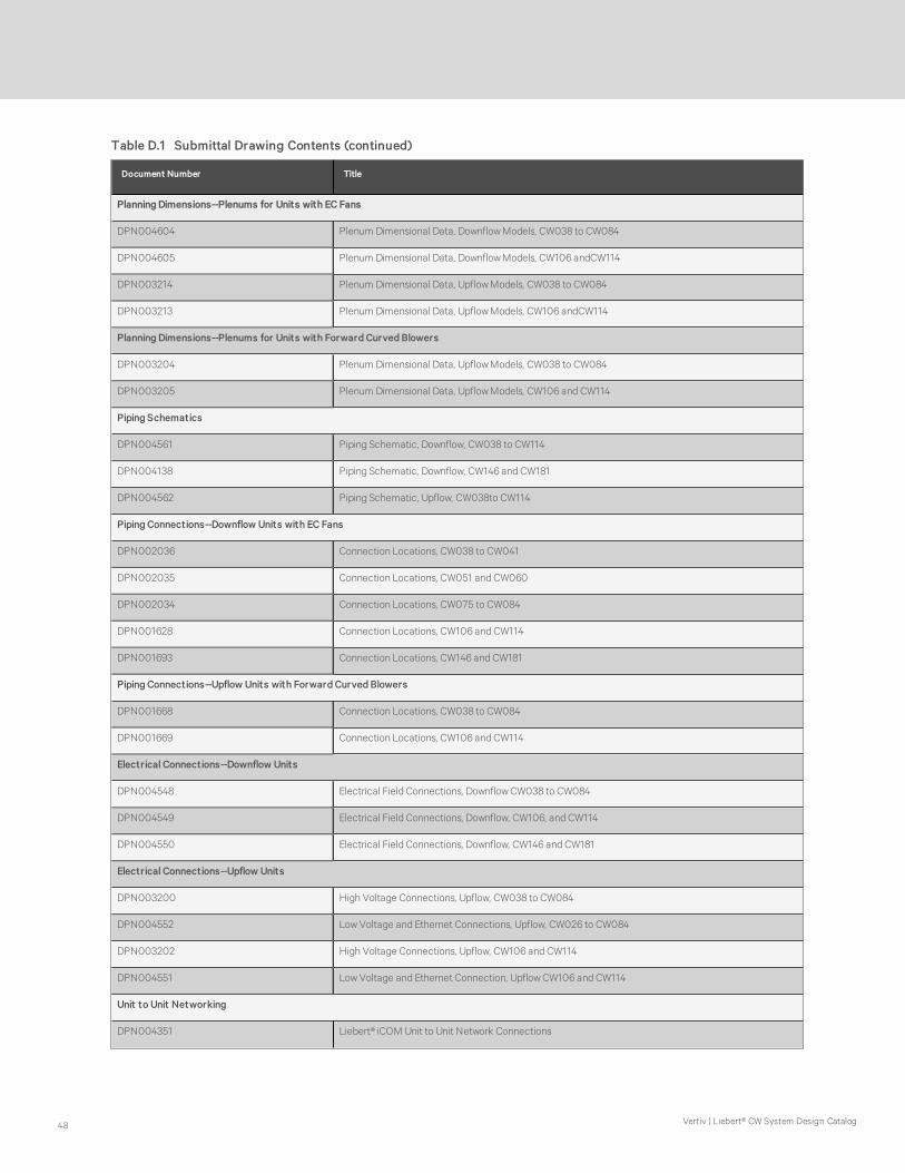
Document Number Title
Planning Dimensions--Plenums for Units with EC Fans
DPN004604 Plenum Dimensional Data, Downflow Models, CW038 to CW084
DPN004605 Plenum Dimensional Data, Downflow Models, CW106 andCW114
DPN003214 Plenum Dimensional Data, Upflow Models, CW038 to CW084
DPN003213 Plenum Dimensional Data, Upflow Models, CW106 andCW114
Planning Dimensions--Plenums for Units with Forward Curved Blowers
DPN003204 Plenum Dimensional Data, Upflow Models, CW038 to CW084
DPN003205 Plenum Dimensional Data, Upflow Models, CW106 and CW114
Piping Schematics
DPN004561 Piping Schematic, Downflow, CW038 to CW114
DPN004138 Piping Schematic, Downflow, CW146 and CW181
DPN004562 Piping Schematic, Upflow, CW038to CW114
Piping Connections--Downflow Units with EC Fans
DPN002036 Connection Locations, CW038 to CW041
DPN002035 Connection Locations, CW051 and CW060
DPN002034 Connection Locations, CW075 to CW084
DPN001628 Connection Locations, CW106 and CW114
DPN001693 Connection Locations, CW146 and CW181
Piping Connections--Upflow Units with Forward Curved Blowers
DPN001668 Connection Locations, CW038 to CW084
DPN001669 Connection Locations, CW106 and CW114
Electrical Connections--Downflow Units
DPN004548 Electrical Field Connections, Downflow CW038 to CW084
DPN004549 Electrical Field Connections, Downflow, CW106, and CW114
DPN004550 Electrical Field Connections, Downflow, CW146 and CW181
Electrical Connections--Upflow Units
DPN003200 High Voltage Connections, Upflow, CW038 to CW084
DPN004552 Low Voltage and Ethernet Connections, Upflow, CW026 to CW084
DPN003202 High Voltage Connections, Upflow, CW106 and CW114
DPN004551 Low Voltage and Ethernet Connection, Upflow CW106 and CW114
Unit to Unit Networking
DPN004351 Liebert® iCOM Unit to Unit Network Connections
Table D.1 Submittal Drawing Contents (continued)
Vertiv | Liebert® CW System Design Catalog48

Document Number Title
Air Economizer Option
DPN001333 Air Economizer Ducting
DPN003226 Planning Dimensions for CW106 to CW114 Downflow Models
DPN003227 Planning Dimensions for CW038 to CW084 Downflow Models
DPN001449 Air Economizer Field Connections
Liebert® CW Seismic Application
DPN003209 Seismic Application Assumptions and Requirements
Table D.1 Submittal Drawing Contents (continued)
Liebert® CW System Design Catalog 49

REV : 5REV DATE : 3/18
DPN002869Page :1 /1
DOWNFLOW MODELS
For
m N
o.: D
PN
0010
40_R
EV
4
COMPONENT LOCATION
LIEBERT CW
Front View
3
6
Rear View
1. iCOM Control Display
2. Electric Box
3. Filters
4. Coil
5. Infrared Humidifier (optional)
6. Reheat (optional)
7. Disconnect
8. Condensate Pump (optional)
9. EC Fans
10. Smoke Detector (optional)
Ships loose for field installationon CW026-CW060 units.
1
7
10
9
5
8
4
2

REV : 3REV DATE : 1/17
DPN002868Page :1 /1
UPFLOW MODELS
For
m N
o.: D
PN
0010
40_R
EV
4
COMPONENT LOCATION
LIEBERT CW
Optional Forward-Curved Blower ConfigurationFront View
1
2
3
4
56
7
8
9
11
12
13
14
10
15
Optional EC Fan ConfigurationFront View
Optional EC Fan ConfigurationRear View
1. iCOM Control Display
2. Electric Box
3. Filters
4. Coil
5. Motor
6. Blower
7. Fan Pulley
8. Motor Sheave & Belts
9. Infrared Humidifier (optional)
10. Reheat (optional)
11. Disconnect (optional)
12. Condensate Pump (optional)
13. Variable Frequency Drive (optional)
14. Plenum with EC Fans (optional)
15. Smoke Detector (optional)
Ships loose for field installationon bottom return units.
Ships loose forfield installation

REV : 5REV DATE : 6/17
DPN003192Page :1 /1
DOWNFLOW MODELS CW038 - CW084 W/ EC FANS
For
m N
o.: D
PN
0010
40_R
EV
4
CABINET DIMENSIONAL DATA
LIEBERT CW
CW038 840 (381)
CW041 900 (408)
CW051 1220 (553)
CW060 1250 (567)
CW076 1440 (653)
CW084 1540 (690)
50 (1270) 46 (1168)
35 (889) 32 (813)
48 (1219)
35 5/8 (905)
NET WT.
lb. (kg)F GE H J
DIMENSIONAL DATA inches (mm)CHILLED
WATER
MODELA B C D
74 (1880)
99 (2515) 8 7/8 (225)
72 (1829)
97 (2464)
31 (787)
28 (711)
2 7/8 (73)
51 1/4 (1302)
60 3/4 (1543)
70 (1778)
95 (2413)
UNIT DIMENSIONAL DATA
CCABINET
DAIR
RETURN AOVERALL
B AIRRETURN
MODELSW/ PRE-FILTERS
F PLENUMOVERALL
GAIR RETURN
AUNIT & PLENUM OVERALL
BAIR RETURN
STANDARD PIPING, ELECTRICAL & AIR DISCHARGE OPENINGS
72"1829mm
72"1829mm
9"229mm
FOVERALL
FRONT OF UNIT
FRONT OF UNIT
FRONT OF UNIT
SHADED AREA INDICATES A RECOMMENDEDCLEARANCE OF 36" (914mm) BE PROVIDEDFOR COMPONENT ACCESS AND FILTER REMOVALON ALL CW026-CW084 UNIT TYPES
SHADED AREA INDICATESA RECOMMENDED CLEARANCE
OF 36" (914mm) BE PROVIDEDFOR COMPONENT ACCESS AND
FILTER REMOVAL ON ALLCW026-CW084 UNIT TYPES
NOTES:1. MINIMUM CLEARANCE OF 24" (610mm) REQUIRED BELOW THE UNIT TO LOWER THE FANS. FANS MAY ALSO REMAIN IN UNIT IF DESIRED.2. VIEWS OF ELECTRICAL & AIR DISCHARGE OPENINGS ARE FROM INSTALLER'S POINT OF VIEW.
CW038 - 041ElectricalOpenings
Standard PipingOpening
E
H
31"787mm
33"838mm
J
CW051 - 060
E H
24 1/4"615mm
24 1/2"624mm
33"838mm
31"787mmTYP.
Standard PipingOpening
ElectricalOpenings
CW076 - 084
E H
28 1/16"713mm
28 1/16"713mm J
33"838mm
31"787mmTYP.
StandardPipingOpening
J
ElectricalOpenings

REV : 3REV DATE : 6/17
DPN003222Page :1 /1
DOWNFLOW CW038 - CW041 W/ EC FANS & FRONT DISCHARGE
For
m N
o.: D
PN
0010
40_R
EV
4
CABINET DIMENSIONAL DATA
LIEBERT CW
Notes: 1. Customer piping and wiring connections a) Standard bottom connections require unit to be placed on a minimum of a 9" floorstand. b) If unit is to be placed directly on the floor, additional modifications are required to relocate customer connections. Contact your local Liebert Sales Representative.
H
W
2"51mm
3"76mm
48"1219mm
AIR DISCHARGEOPENING
72"1829mm
50"1270mm
33"838mm
35"889mm
31"787mm
Opening
46"1168mm Opening
Striated area indicates therecommended minimumclearance to be providedfor component access.
36"914mm
RETURN AIR OPENING
TOP VIEW
FRONT VIEW
1 3/4"44mm Handle
5/16"8mm Bezel
36"914mm
Model H W Dry Weight lbs. (kg)
CW038 840 (381)
CW041 900 (408)16-1/16" (408mm) 29-11/16" (754mm)
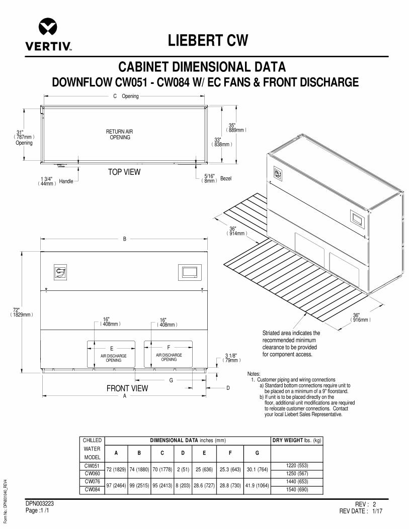
REV : 2REV DATE : 1/17
DPN003223Page :1 /1
DOWNFLOW CW051 - CW084 W/ EC FANS & FRONT DISCHARGE
For
m N
o.: D
PN
0010
40_R
EV
4
CABINET DIMENSIONAL DATA
LIEBERT CW
Striated area indicates therecommended minimumclearance to be providedfor component access.
36"916mm
36"914mm
A
B
72"1829mm
C Opening
31"787mmOpening
35"889mm
33"838mm
D
3 1/8"79mm
F E
16"408mm
16"408mm
AIR DISCHARGEOPENING
AIR DISCHARGEOPENING
G
DRY WEIGHT lbs. (kg)
A B C D E F G
CW051 1220 (553)
CW060 1250 (567)
CW076 1440 (653)
CW084 1540 (690)
DIMENSIONAL DATA inches (mm)CHILLED
WATER
MODEL
72 (1829)
97 (2464)
74 (1880)
99 (2515)
70 (1778)
95 (2413)
30.1 (764)
41.9 (1064)
2 (51)
8 (203)
25 (636)
28.6 (727)
25.3 (643)
28.8 (730)
FRONT VIEW
TOP VIEW
RETURN AIR OPENING
Notes: 1. Customer piping and wiring connections a) Standard bottom connections require unit to be placed on a minimum of a 9" floorstand. b) If unit is to be placed directly on the floor, additional unit modifications are required to relocate customer connections. Contact your local Liebert Sales Representative.
1 3/4"44mm Handle
5/16"8mm Bezel
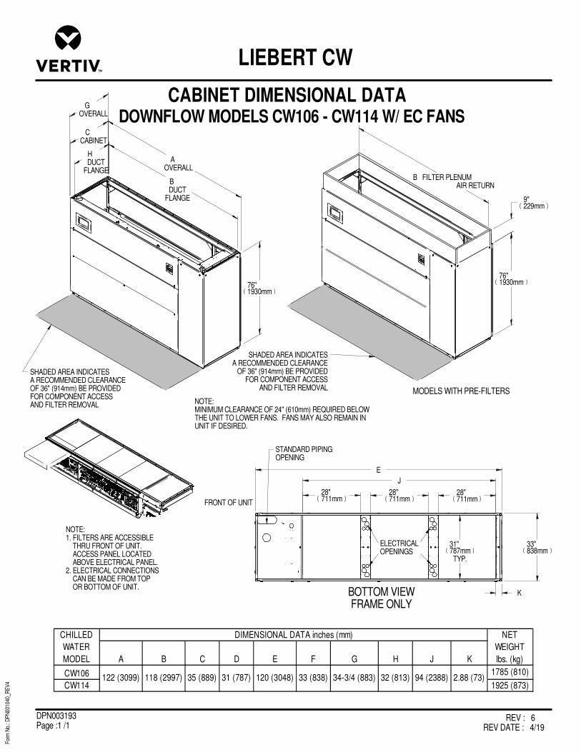
REV : 6REV DATE : 4/19
DPN003193Page :1 /1
For
m N
o.: D
PN
0010
40_R
EV
4
CABINET DIMENSIONAL DATA
LIEBERT CW
DOWNFLOW MODELS CW106 - CW114 W/ EC FANSG
OVERALL
CCABINET
AOVERALL
76"1930mm
MODELS WITH PRE-FILTERS
76"1930mm
9"229mm
B FILTER PLENUMAIR RETURN
HDUCT
FLANGE
BDUCT
FLANGE
BOTTOM VIEWFRAME ONLY
E
J
28"711mm
28"711mm
28"711mm
31"787mmTYP.
33"838mm
K
FRONT OF UNIT
CW106 1785 (810)
CW114 1925 (873)122 (3099) 118 (2997) 35 (889) 31 (787) 120 (3048)
CHILLED
WATER
MODEL
DIMENSIONAL DATA inches (mm) NET
WEIGHT
lbs. (kg)A B C D E F G H J K
33 (838) 34-3/4 (883) 32 (813) 94 (2388) 2.88 (73)
SHADED AREA INDICATESA RECOMMENDED CLEARANCEOF 36" (914mm) BE PROVIDEDFOR COMPONENT ACCESSAND FILTER REMOVAL
STANDARD PIPINGOPENING
ELECTRICALOPENINGS
NOTE:1. FILTERS ARE ACCESSIBLE THRU FRONT OF UNIT. ACCESS PANEL LOCATED ABOVE ELECTRICAL PANEL.2. ELECTRICAL CONNECTIONS CAN BE MADE FROM TOP OR BOTTOM OF UNIT.
SHADED AREA INDICATESA RECOMMENDED CLEARANCE
OF 36" (914mm) BE PROVIDEDFOR COMPONENT ACCESS
AND FILTER REMOVAL
NOTE:MINIMUM CLEARANCE OF 24" (610mm) REQUIRED BELOWTHE UNIT TO LOWER FANS. FANS MAY ALSO REMAIN INUNIT IF DESIRED.

REV : 4REV DATE : 6/19
DPN003224Page :1 /1
DOWNFLOW CW106 - CW114 W/ EC FANS & FRONT DISCHARGE
For
m N
o.: D
PN
0010
40_R
EV
4
CABINET DIMENSIONAL DATA
LIEBERT CW
118"2997mm Opening
30 3/4"781mm
Opening
Striated area indicates therecommended minimumclearance to be providedfor component access.
36"914mm
33"838mm
35"889mm
122"3099mm
76"1930mm
120"3048mm
1 1/2"37mm
3 1/8"80mm
15 7/8"403mm TYP. (3) PLACES
30 1/8"765mm
1 3/4"45mm
29 7/8"757mm
28 7/8"732mm
1 3/4"45mm
3 1/8"80mm
15 7/8"403mm TYP. (3) PLACES
28 7/8"732mm
29 7/8"757mm
30 1/8"765mm
Notes: 1. Filters are accessible from front of unit only. 2. Customer piping and wiring connections a) Standard bottom connections require unit to be placed on a minimum of a 9" floorstand. b) If unit is to be placed directly on the floor, additional unit modifications are required to relocate customer connections. Contact your local Liebert Sales Representative.
REAR VIEW
FRONT VIEW
TOP VIEW
AIR DISCHARGEOPENING
AIR DISCHARGEOPENING
AIR DISCHARGEOPENING
AIR DISCHARGEOPENING
AIR DISCHARGEOPENING
AIR DISCHARGEOPENING
RETURN AIR OPENING
35"889mm
67 7/8"1725mm
35"889mm
67 7/8"1725mm
1 3/4"44mm Handle5/16"
8mm Bezel
Model Dry Weight lbs. (kg)
CW106 1785 (810)
CW114 1925 (873)

REV : 2REV DATE : 1/17
DPN003208Page :1 /1
DOWNFLOW CW146 & CW181 W/ EC FANS AND FILTER PLENUM(plenum shipped separately)
For
m N
o.: D
PN
0010
40_R
EV
4
CABINET DIMENSIONAL DATA
LIEBERT CW
76"1930mm
BASE UNIT
45"1143mm
PLENUM
18"457mm
FILTER PLENUM
42"1067mmOpening
94"2388mm
TOTAL HEIGHT
1 1/2"38mm
120"3044mm45"
1143mm
47"1194mm
1"25mm
TYP122"3099mm
1 3/4"44mm Handle
5/16"8mm Bezel
48"1219mm
24"610mm
117 11/16"2989mm Opening
MODEL DRY WEIGHT lbs. (kg)
CW146
CW1812520 (1143)
Notes:
1. Striated area indicates the recommended minimum clearance to be provided for component access.
2. Shaded area indicates the required minimum clearance below the unit to lower the fans into the floor. Fans may also remain in their shipped position if desired. 3. Filter Plenum shipped separately
4. CW146 or CW181 base unit
5. Filters are removed through the front of the plenum.
6. Reference DPN001693 for the electrical and plumbing requirements.
1
2
3
4
5

REV : 3REV DATE : 6/17
DPN003225Page :1 /1
DOWNFLOW CW146 & CW181 W/ EC FANS & FRONT DISCHARGE
For
m N
o.: D
PN
0010
40_R
EV
4
CABINET DIMENSIONAL DATA
LIEBERT CW
CW146 or CW181 base unit
Filter Plenum (shipped separately)
Striated area indicates the recommended minimum clearanceto be provided for component access.
Filters are removedthrough the front of the plenum.
48"1219mm
76"1930mm
BASE UNIT
18"457mm
FILTER PLENUM
42"1067mmOpening
117 11/16"2989mmOpening
93 15/16"2386mm
TOTAL HEIGHT
1 1/2"38mm
120"3048mm
122"3099mm
29 1/2"749mm
27 9/16"700mm
30 11/16"779mm
18 13/16"478mm TYP.
(3) PLACES
AIR DISCHARGEOPENING
AIR DISCHARGEOPENING
AIR DISCHARGEOPENING
3 1/4"83mm
1 1/2"38mm
30 11/16"779mm
27 9/16"700mm
29 1/2"749mm
18 13/16"478mm
TYP. (3) PLACES
AIR DISCHARGEOPENING
AIR DISCHARGEOPENING
AIR DISCHARGEOPENING
1 1/2"38mm
3 1/4"83mm
TOP VIEW
FRONT VIEW
REAR VIEW36 3/8"924mm
68 1/4"1734mm
36 3/8"924mm
68 1/4"1734mm
Notes:1. Standard bottom connections require unit to be placed on a minimum of 9" floorstand. 2. If unit is to be placed on the floor an opening is provided in front left end panel for piping and high voltage wire routings (See Detail A). - customer must drill holes in right end panel to route low volt connections to standard location (must be routed separate from any high voltage wires).
45"1143mm
PLENUM
45"1143mm
1"25mm
3 1/16"78mm
4 5/8"117mm
LEFT SIDE
5/16"8mm Bezel1 3/4"
44mm Handle
A
DETAIL A 9 5/8"244mm
15"381mm
46 3/4"1188mm
2
MODEL DRY WEIGHT lbs. (kg)
CW146
CW1812520 (1143)

REV : 4REV DATE : 10/18
DPN003215Page :1 /2
UPFLOW MODELS CW038 - CW084 W/ EC FANS
For
m N
o.: D
PN
0010
40_R
EV
4
CABINET DIMENSIONAL DATA
LIEBERT CW
CBASE
1"25mm
33" 838mmBASE
PROJECTION OFDISPLAY BEZEL
BOVERALL
35"889mm
OVERALL
72"1829mm
UNIT
APLENUM
NOTE: DUCT FLANGES ON PLENUM TOP FOR SUPPLY AIR DUCTING WHEN SOLID PANEL PLENUM IS USED.
1"25mm
SHADED AREASINDICATE A RECOMMENDED
CLEARANCE OF 36" (914mm) BEPROVIDED FOR COMPONENT
ACCESS AND FILTER REMOVAL. FORRECOMMENDED MINIMUM
CLEARANCE REFER TO THEINSTALLATION MANUAL.
SEE DPN003214 FOR PLENUMCLEARANCES.
72"1829mm
75 1/4"1911mm
EC FAN TERMINAL BOX
3/4"19mm
LEFT SIDE DETAIL VIEW WITHOUT PLENUM OR EC FANS
SUPPLY AIR
GRILLE DISCHARGE
TOP DISCHARGE 22.75 (578), 30 (762), 36 (914)
22.75 (578)
DIMENSION A
PLENUM HEIGHT DATA in (mm)
RETURN AIR GRILLESUPPLIED ON
UNITS WITH FRONT RETURN
FRONT AIR RETURN MODEL SHOWN
MODEL B C UNIT ONLY UNIT W/ PLENUM & FANS
CW038 542 (246) 774 (351)
CW041 589 (267) 821 (372)
CW051 755 (342) 1118 (507)
CW060 827 (375) 1190 (540)
CW076 1141 (518) 1566 (710)
CW084 1239 (562) 1664 (755)
UNIT DIMENSIONAL DATA in. (mm) NET WEIGHT lbs. (kg)
74 (1880)
99 (2515
72 (1829)
97 (2464)
50 (1270) 48 (1219)

REV : 4REV DATE : 10/18
DPN003215Page :2 /2
UPFLOW MODELS CW038 - CW084 W/ EC FANS
For
m N
o.: D
PN
0010
40_R
EV
4
CABINET DIMENSIONAL DATA
LIEBERT CW
1"25mm
C
B
A
D
REAR AIR RETURN MODEL
RETURN AIR OPENING
BOTTOM VIEW
33"838mm
31"787mm
F
E
FRONT OF UNIT BOTTOM AIR RETURN MODEL
CW038
CW041
CW051
CW060
CW076
CW084
CHILLED
WATER
MODELA
44 (1118)
68 (1727)
86 (2184)
Dimensional Data in. (mm)
B C D E F
18 (457)
20 (508)
18 (457)
5 (127)
4 (102)
5 (127)
3 (76)
6-1/2 (165) 95 (2413)
70 (1778)
46 (1168)
97 (2464)
72 (1829)
48 (1219)
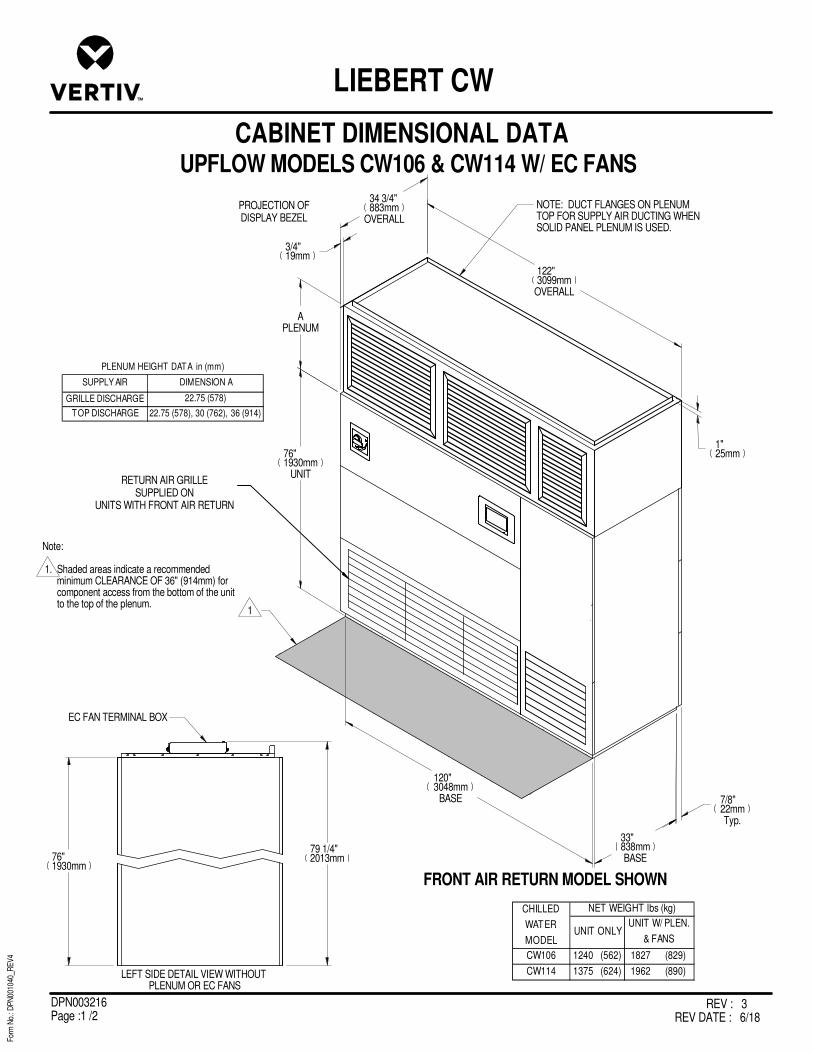
REV : 3REV DATE : 6/18
DPN003216Page :1 /2
UPFLOW MODELS CW106 & CW114 W/ EC FANS
For
m N
o.: D
PN
0010
40_R
EV
4
CABINET DIMENSIONAL DATA
LIEBERT CW
RETURN AIR GRILLESUPPLIED ON
UNITS WITH FRONT AIR RETURN
120" 3048mm
BASE 7/8"22mmTyp.
33" 838mmBASE
PROJECTION OFDISPLAY BEZEL
122"3099mm
OVERALL
76"1930mm
UNIT
APLENUM
NOTE: DUCT FLANGES ON PLENUM TOP FOR SUPPLY AIR DUCTING WHEN SOLID PANEL PLENUM IS USED.
1"25mm
76"1930mm
79 1/4"2013mm
EC FAN TERMINAL BOX
LEFT SIDE DETAIL VIEW WITHOUT PLENUM OR EC FANS
FRONT AIR RETURN MODEL SHOWN
SUPPLY AIR
GRILLE DISCHARGE
TOP DISCHARGE 22.75 (578), 30 (762), 36 (914)
22.75 (578)
DIMENSION A
PLENUM HEIGHT DATA in (mm)
Note:
1. Shaded areas indicate a recommended minimum CLEARANCE OF 36" (914mm) for component access from the bottom of the unit to the top of the plenum.
1
CW106 1240 (562) 1827 (829)
CW114 1375 (624) 1962 (890)
CHILLED
WATER
MODELUNIT ONLY
UNIT W/ PLEN.
& FANS
NET WEIGHT lbs (kg)
3/4"19mm
34 3/4"883mm
OVERALL

REV : 3REV DATE : 6/18
DPN003216Page :2 /2
UPFLOW MODELS CW106 & CW114 W/ EC FANS
For
m N
o.: D
PN
0010
40_R
EV
4
CABINET DIMENSIONAL DATA
LIEBERT CW
24 1/4"616mm
2 1/4"57mm
117 1/2"2984mm
RETURN AIR DUCT
CONNECTION DATAMODELS WITH REAR RETURN
SHADED AREA INDICATES A RECOMMENDEDCLEARANCE OF 25" (635mm) BE PROVIDED FORREAR RETURN FILTER REMOVAL ON ONE ENDOF THE UNIT.
RETURN AIR FILTER OPENING
22"559mm
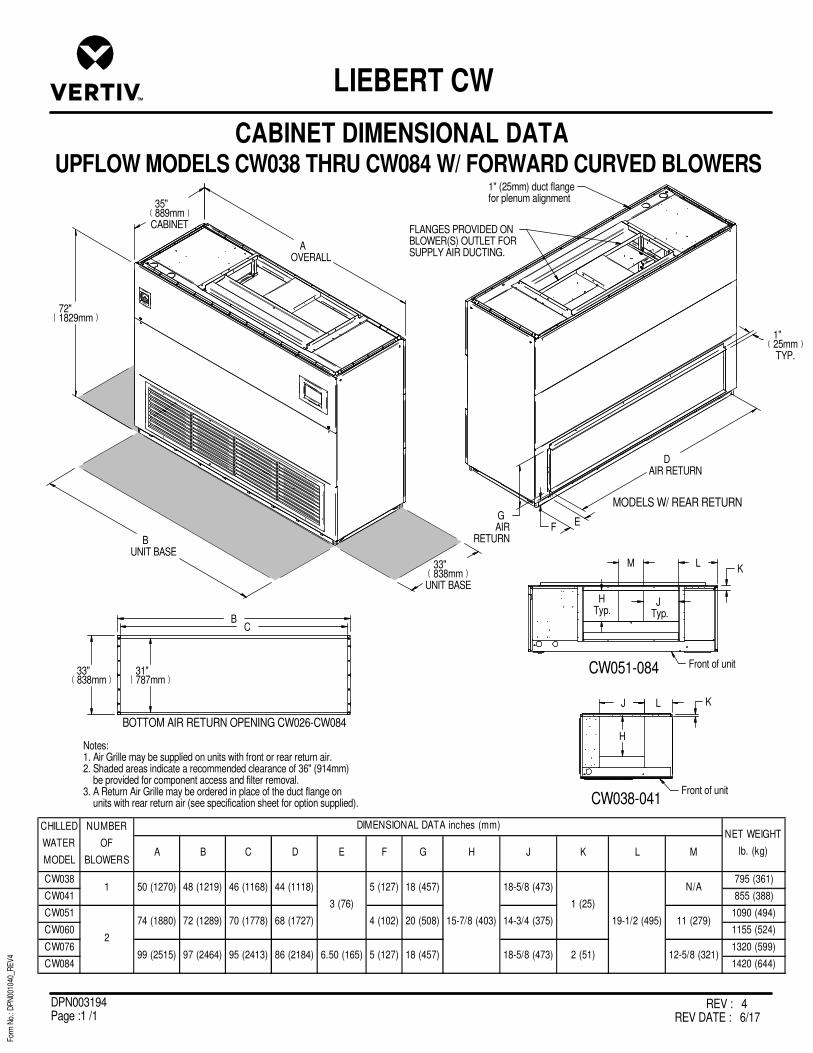
REV : 4REV DATE : 6/17
DPN003194Page :1 /1
UPFLOW MODELS CW038 THRU CW084 W/ FORWARD CURVED BLOWERS
For
m N
o.: D
PN
0010
40_R
EV
4
CABINET DIMENSIONAL DATA
LIEBERT CW
MODELS W/ REAR RETURN
AOVERALL
35"889mm
CABINET
72"1829mm
33"838mm
UNIT BASE
BUNIT BASE
DAIR RETURN
FGAIR
RETURN
BOTTOM AIR RETURN OPENING CW026-CW084
C
31"787mm
B
33"838mm
E
CW038 795 (361)
CW041 855 (388)
CW051 1090 (494)
CW060 1155 (524)
CW076 1320 (599)
CW084 1420 (644)
NET WEIGHT
lb. (kg)
CHILLED
WATER
MODEL
NUMBER
OF
BLOWERS
DIMENSIONAL DATA inches (mm)
A B C D E F G H J K L M
2
74 (1880)
99 (2515)
1 50 (1270)
72 (1289)
97 (2464)
70 (1778)
95 (2413)
48 (1219) 46 (1168)
68 (1727)
86 (2184) 6.50 (165)
44 (1118)
3 (76)
4 (102)
5 (127)
20 (508)
18 (457)
5 (127) 18 (457)
14-3/4 (375)
18-5/8 (473) 2 (51)
15-7/8 (403)
1 (25)
18-5/8 (473)
11 (279)
12-5/8 (321)
19-1/2 (495)
N/A
Notes:1. Air Grille may be supplied on units with front or rear return air.2. Shaded areas indicate a recommended clearance of 36" (914mm) be provided for component access and filter removal.3. A Return Air Grille may be ordered in place of the duct flange on units with rear return air (see specification sheet for option supplied).
1"25mmTYP.
1" (25mm) duct flangefor plenum alignment
FLANGES PROVIDED ONBLOWER(S) OUTLET FORSUPPLY AIR DUCTING.
CW038-041
J L
CW051-084
HTyp.
JTyp.
M L
K
K
Front of unit
Front of unit
H

REV : 4REV DATE : 6/18
DPN003195Page :1 /1
UPFLOW MODELS CW106, CW114 W/ FORWARD CURVED BLOWERS
For
m N
o.: D
PN
0010
40_R
EV
4
CABINET DIMENSIONAL DATA
LIEBERT CW
A B C D E F
TOP FRONT 2-3/4 (70)
TOP REAR 11-1/2 (292)
10-15
20
TOP REAR 10-20 11-1/2 (292)
10-1515 x 15 18-5/8 (473)
2-3/4 (70)
CW106
CW114 15 x 11
MODEL BLOWER
TOP FRONT
26-1/4 (667)
MOTOR
HP
NET WT.
lbs. (kg)
1785 (810)
1925 (873)
DIMENSIONAL DATA inches (mm)SUPPLY
14 3/4 (375)
15-7/8 (403) 10 (254) 4-1/2 (114)
28-1/4 (718)
122"3099mm
OVERALL
118"2997mm
PLENUM FLANGE
34 3/4"883mm
CABINET
32"813mm
PLENUMFLANGE
76"1930mm
33"838mmBASE
120"3048mm
BASE
MODELS WITH REAR RETURN
1" DUCT FLANGE FORPLENUM ALIGNMENT
FLANGES PROVIDED ONBLOWER OUTLETS FORSUPPLY AIR DUCTING
FILTER ACCESSBOTH ENDS
SHADED AREA INDICATESA RECOMMENDED CLEARANCE
OF 36" (914mm) BE PROVIDEDFOR COMPONENT ACCESS
AND FILTER REMOVAL. FORRECOMMENDED MINIMUM CLEARANCEREFER TO THE INSTALLATION MANUAL.
24 1/4"616mm
2 1/4"57mm
4"102mm
SHADED AREA INDICATESA RECOMMENDED
CLEARANCE OF 25" (635mm)BE PROVIDED FOR REAR
RETURN FILTER REMOVALON ONE END OF UNIT.
22"559mm
117 1/2"2984mm
AIR RETURNOPENING
AIR GRILLE MAY BE SUPPLIEDON UNITS WITH FRONT RETURNAIR ONLY.
FRONT OF UNITRIGHT SIDE OF UNIT
FRONT OR REARRETURN AIR
FBLOWER DECK
C E
C E
C A
D
B
122"3099mm

REV : 3REV DATE : 6/17
DPN003212Page :1 /1
DOWNFLOW MODELS CW038 & CW041 W/ EC FANS
For
m N
o.: D
PN
0010
40_R
EV
4
FLOORSTAND & FLOOR PLANNING DIMENSIONAL DATA
LIEBERT CW
NOTE:1. This floor stand should be used when EC fans are intended to be lowered under a raised floor. The standard Liebert CW floor stand can be used “if” the fans are to remain in their original raised position.2. All paneled sides of unit overhang floorstand 1” (25mm).3. The floor stand used with EC units is not symmetrical and its orientation to the Liebert CW is critical for lowering the EC fans. Unless the floor stand is installed in the correct position, the blowers will not lower into the floor stand.4. Jack and jack support are shipped loose and are intended to be placed into position under each fan and utilized to lower or raise that fan as needed.5. Not applicable to 24" high floorstand.
6. Leveling feet are provided with u 1-1/2” (38mm) adjustment from nominal height “A”.
See note 4
Piping access area
Height in ( mm )
A
24 (610)
30 (762)
36 (914)
42 (1067)
48 (1219)
1"25mm
14"356mm
3/4"19mm
31 1/2"800mm
CENTER FEET
3/4"19mm
46 1/2"1181mm
CENTER FEET
48"1219mm
3/4"19mm
7/8"23mm
3"76mm
49 1/2"1257mm
33"838mm
3/4"19mm
A
19 1/4"489mm
5
6
6

REV : 2REV DATE : 1/17
DPN003211Page :1 /1
DOWNFLOW MODELS CW051 & CW060 W/ EC FANS
For
m N
o.: D
PN
0010
40_R
EV
4
FLOORSTAND & FLOOR PLANNING DIMENSIONAL DATA
LIEBERT CW
NOTE:1. This floor stand should be used when EC fans are intended to be lowered under a raised floor. The standard Liebert CW floor stand can be used if the fans are to remain in their original raised position.
2. All paneled sides of unit overhang floorstand 1” (25mm).
3. The floor stand used with EC units is not symmetrical and its orientation to the Liebert CW is critical for lowering the EC fans. Unless the floor stand is installed in the correct position, the blowers will not lower into the floor stand.
4. Jack and jack support are shipped loose and are intended to be placed into position under each fan and utilized to lower or raise that fan as needed.
5. Does not apply to 24 " high floorstand.
*Leveling feet are provided with u 1-1/2” (38mm) adjustment from nominal height “A”.
See note 4
Height in ( mm )A*
24 (610)30 (762)36 (914)
42 (1067)48 (1219)
1"25mm
15 3/4"400mm
3/4"19mm
31 9/16"801mm
CENTER FEET
3/4"19mm
70 9/16"1792mm
CENTER FEET
3/4"20mm
72"1829mm
7/8"23mm
3"76mm 73 9/16"
1868mm
A*
33"838mm
19 1/4"489mm
Piping access area
5

REV : 2REV DATE : 1/17
DPN003210Page :1 /1
DOWNFLOW MODELS CW076 & CW084 W/ EC FANS
For
m N
o.: D
PN
0010
40_R
EV
4
FLOORSTAND & FLOOR PLANNING DIMENSIONAL DATA
LIEBERT CW
NOTE:1. This floor stand should be used when EC fans are intended to be lowered under a raised floor. The standard Liebert CW floor stand can be used “if” the fans are to remain in their original raised position.
2. All paneled sides of unit overhang floorstand 1” (25mm).
3. The floor stand used with EC units is not symmetrical and its orientation to the Liebert CW is critical for lowering the EC fans. Unless the floor stand is installed in the correct position, the blowers will not lower into the floor stand.
4. Jack and jack support are shipped loose and are intended to be placed into position under each fan and utilized to lower or raise that fan as needed.
5. Does not apply to 24" high floorstand.
*Leveling feet are provided with u 1-1/2” (38mm) adjustment from nominal height “A”.
Piping access area
SEE NOTE 4
Height in ( mm )A*
24 (610)30 (762)36 (914)
42 (1067)48 (1219)
25"635mm
1"25mm
3/4"19mm
31 1/2"801mm
CENTER FEET
3/4"19mm
95 1/2"2427mm
CENTER FEET
31 7/8"809mm
CENTER FEET(2) PLACES
47 7/8"1215mm
CENTER FEET
3/4"20mm
97"2464mm
7/8"23mmTYP.
3"76mm TYP.
98 1/2"2503mm
A*
19 1/4"489mm
33"838mm
5
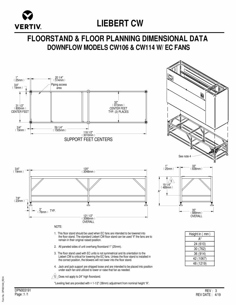
REV : 3REV DATE : 4/19
DPN003191Page :1 /1
DOWNFLOW MODELS CW106 & CW114 W/ EC FANS
For
m N
o.: D
PN
0010
40_R
EV
4
FLOORSTAND & FLOOR PLANNING DIMENSIONAL DATA
LIEBERT CW
Piping accessarea
NOTE:
1. This floor stand should be used when EC fans are intended to be lowered into the floor stand. The standard Liebert CW floor stand can be used “if” the fans are to remain in their original raised position.
2. All paneled sides of unit overhang floorstand 1” (25mm).
3. The floor stand used with EC units is not symmetrical and its orientation to the Liebert CW is critical for lowering the EC fans. Unless the floor stand is installed in the correct position, the blowers will not lower into the floor stand.
4. Jack and jack support are shipped loose and are intended to be placed into position under each fan and utilized to lower or raise that fan as needed.
5. Does not apply to 24" high floorstand.
*Leveling feet are provided with u 1-1/2” (38mm) adjustment from nominal height “A”.
See note 4
Height in ( mm )
A*
24 (610)
30 (762)
36 (914)
42 (1067)
48 (1219)
SUPPORT FEET CENTERS
20 1/4"514mm
1"25mm
3/4"19mm
31 1/2"800mm
CENTER FEET
3/4"19mm
59 1/4"1505mm
118 1/2"3010mm
3/4"19mm
120"3048mm
7/8"23mm
3"76mm TYP.
121 1/2"3086mm
OVERALL
32"813mm
CENTER FEETTYP. (2) PLACES
33"838mm
1"25mm
A*
19 1/4"489mm
35"889mm
OVERALL
5

REV : 2REV DATE : 1/17
DPN003207Page :1 /1
DOWNFLOW MODELS CW146 & CW181 W/ EC FANS
For
m N
o.: D
PN
0010
40_R
EV
4
FLOORSTAND & FLOOR PLANNING DIMENSIONAL DATA
LIEBERT CW
Piping accessarea
SUPPORTING FEET CENTERS
3"76mm
7/8"23mmTYP
A*
Height in ( mm )A*
24 (610)30 (762)36 (914)
42 (1067)48 (1219)
See note 4
NOTE:1. This floor stand should be used when EC fans are intended to be lowered into the floor stand. The standard Liebert CW floor stand can be used “if” the fans are to remain in their original raised position.
2. All paneled sides of unit overhang floorstand 1” (25mm).
3. The floor stand used with EC units is not symmetrical and its orientation to the Liebert CW is critical for lowering the EC fans. Unless the floor stand is installed in the correct position, the blowers will not lower into the floor stand.
4. Jack and jack support are shipped loose and are intended to be placed into position under each fan and utilized to lower or raise that fan as needed.
5. Does not apply to 24" & 30" high floorstands.
*Leveling feet are provided with u 1-1/2” (38mm) adjustment from nominal height “A”.
120"3048mm
3/4"19mmTYP
121 1/2"3086mm
OVERALL WIDTH
47"1194mm
OVERALL DEPTH
45"1143mm
1"25mmTYP
43 1/2"1105mm
3/4"19mm
59 1/4"1505mm
118 1/2"3010mm
3/4"19mm
44"1118mm
CENTER FEET
1"25mm
20 1/4"514mm
25 1/4"641mm
5

REV : 3REV DATE : 6/17
DPN001676Page :1 /1
CW038-084 UPFLOW MODELS
For
m N
o.: D
PN
0010
40_R
EV
4
FLOORSTAND & FLOOR PLANNING DIMENSIONAL DATA
LIEBERT CW
1(25.4mm)
"
8(203mm)
3(76.2mm)
(25.4mm)1
"
"
"
B
A
C
STANDARDPIPING ANDELECTRICALENTRANCELOCATION
E
D
OPTIONAL STEAM/HOT WATERREHEAT PIPING ENTRANCELOCATION
1"(25.4mm)
2"(50.8mm)
16 1/4"(413mm)
H _ 1 1/2" (38mm) *+
LEG SUPPORT SUPPLIED ON 18, 21 & 24" HIGH MODELS
33"(838mm)
56 3/4"1441mm
CROSS-BRACING LOCATION FOR 72" FRAMES ONLY
62"(1574.8mm)
48" (1219.2mm)72" (1828.8mm)97" (2463.8mm)
1
Notes:
1. Leveling feet are provided with u1-1/2" (38mm) adjustment from nominal height H.
Height in. (mm)
H Nominal
9 (229)
12 (305)
15 (381)
18 (458)
21 (553)
24 (610)
CW038, CW041 50 (1270) 48 (1219) 36 (914)
CW051, CW060 74 (1880) 72 (1829) 60 (1524)
CW076, CW084 99 (2515) 97 (2464) 77-3/4 (1975) 15-1/4 (362)
0
48-1/2 (1232)
8 (203)
Dimensional Data in. (mm)
ModelOverall Width
of UnitA B C D E

REV : 3REV DATE : 6/17
DPN001677Page :1 /1
For
m N
o.: D
PN
0010
40_R
EV
4
FLOORSTAND & FLOOR PLANNING DIMENSIONAL DATA
LIEBERT CW
CW106, CW114 UPFLOW MODELS
H ± 1 1/2" (38mm)
1"(25.4mm)
J
E
1"(25.4mm)
D
STANDARDPIPING ANDELECTRICALENTRANCELOCATION
B
C
A
LEG SUPPORTS SUPPLIED ON 18, 21 & 24" HIGH MODELS
AIR DISCHARGEOPENING
G
ELECTRICAL OPENING
F
120" (3048.0 mm)
1
Height in. (mm)
H Nominal
9 (229)
12 (305)
15 (381)
18 (458)
21 (553)
24 (610)
CW106, CW114 122 (3099) 120 (3048) 33 (838) 100-3/4 (2559) 16-1/4 (413) 8-1/4 (210) 11 (279)
J
60 (1524)
Dimensional Data in. (mm)
ModelOverall Width
of unitA B C D E F G
Notes:
1. Leveling feet are provided with ± 1 1/2" (38mm) adjustment from nominal height H.
1

REV : 0REV DATE : 8/18
DPN004604Page :1 /1
DOWNFLOW MODELS CW038 - CW084 W/ EC FANS
For
m N
o.: D
PN
0010
40_R
EV
4
PLENUM DIMENSIONAL DATA
LIEBERT CW
C
H
BA
D
CD
2"(50mm)
(25mm)1"
1"(25mm)
2"(50mm)
(25mm)1"
(25mm)
1"
(50mm)2"
Plenum Height in. (mm)
H
20 (508)
22-3/4 (578)
34-3/4 (883)
Model A B C D
CW038, CW041 50 (1270) 46 (1168)
CW051, CW060 74 (1880) 70 (1778)
CW076, CW084 99 (2515) 95 (2413)
Plenum Dimensional Data in. (mm)
34 (864) 32 (813)
Flange must be specified onDownflow models.
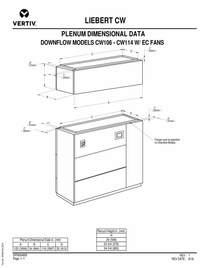
REV : 1REV DATE : 8/18
DPN004605Page :1 /1
For
m N
o.: D
PN
0010
40_R
EV
4
PLENUM DIMENSIONAL DATA
LIEBERT CW
DOWNFLOW MODELS CW106 - CW114 W/ EC FANS
C D
H
B
1"25mm
1"25mm
1"25mm
2"51mm
C
D
2"51mm
Flange must be specifiedon Downflow Models.
A
2"51mm
1"25mm
Plenum Height in. (mm)
H
20 (508)
22-3/4 (578)
34-3/4 (883)A B C D
122 (3099) 34 (864) 118 (2997) 32 (813)
Plenum Dimensional Data in. (mm)

REV : 4REV DATE : 10/18
DPN003214Page :1 /1
UPFLOW MODELS CW038 - CW084 W/ EC FANS
For
m N
o.: D
PN
0010
40_R
EV
4
PLENUM DIMENSIONAL DATA
LIEBERT CW
C
G
B
F
E
A
D
CD
20"508mm)
2"(51mm)
(25mm)1"
1"(25mm)2"
(51mm)
(25mm)1"
(25mm)
1"
(51mm)2"
SUPPLY AIR G
GRILLE & TOP DISCHARGE 22.75 (578)
TOP DISCHARGE ONLY 30 (762)
TOP DISCHARGE ONLY 36 (914)
PLENUM HEIGHT DATA in (mm)
MODEL A B C D E F
CW038, CW041 50 (1270) 46 (1168) 46 (1168) 2 (51) 4.29 (.40)
CW051, CW060 74 (1880) 70 (1778) 62 (1575) 6 (152) 5.85 (.54)
CW076, CW084 99 (2515) 95 (2413) 70 (1778) 14 1/2 ( 368) 6.83 (.63)
GRILL FREE
AREA SQ. FT .
(SQ. METERS)
PLENUM DIMENSIONAL DATA in (mm)
34 (864) 32 (813)
TOP DUCT FLANGES ONPLENUM TOP FOR SUPPLY AIRDUCTING WHEN SOLID PANELPLENUM IS USED.
BOTH TOP DUCT OPENINGS ANDFRONT GRILL ARE SHOWN. SEESPECIFICATION SHEETFOR SPECIFIC APPLICATION.
2"(51mm)
Shaded area indicates a recommended CLEARANCEOF 36" (914mm) be provided for EC Fan Plenum accessfrom the bottom of the unit to the top of the plenum.See DPN003215 for unit clearances.

REV : 2REV DATE : 1/17
DPN003213Page :1 /1
For
m N
o.: D
PN
0010
40_R
EV
4
PLENUM DIMENSIONAL DATA
LIEBERT CW
UPFLOW MODELS CW106, CW114 W/ EC FANS
CD
B
(25mm)
1"(25mm)
1"
(508mm)
1" (25mm)
2" (50.8mm)
C
D1" (25mm)
2"(50mm)
A
E
E
I
20"
J
1.5" (38mm)
F
G
H
MODEL A B C D E F G H I
CW106, CW114 122 (3099) 34 (864) 118 (2997) 32 (813) 44 (1118) 3 (76) 2 (51) 5 (127) 18 (457) 10.14 (.94)
GRILL FREE
AREA SQ. FT.
(SQ. METERS)
PLENUM DIMENSIONAL DATA in (mm)
NOTE: TOP DUCT FLANGES ON PLENUM TOP FOR SUPPLY AIR DUCTING WHEN SOLID PANEL PLENUM IS USED.
BOTH TOP DUCT OPENINGAND GRILLES SHOWN. SEESPEC SHEET FOR SPECIFICAPPLICATION.
SUPPLY AIR J
GRILLE & TOP DISCHARGE 22.75 (578)
TOP DISCHARGE ONLY 30 (762)
TOP DISCHARGE ONLY 36 (914)
PLENUM HEIGHT DATA in (mm)
Shaded areas indicate a recommended CLEARANCEOF 36" (914mm) be provided for component accessfrom the bottom of the unit to the top of the plenum.

REV : 4REV DATE : 9/18
DPN003204Page :1 /1
UPFLOW MODELS CW038 - CW084 W/ FORWARD CURVED BLOWERS
For
m N
o.: D
PN
0010
40_R
EV
4
PLENUM DIMENSIONAL DATA
LIEBERT CW
C
H
B
F
E
A
D
CD
18"(457mm)
J
1"(25mm)
2"(50mm)
(25mm)1"
1"(25mm)
2"(50mm)
(25mm)1"
(25mm)
1"
(50mm)2"
H J
20 (508) 1 (25)
22-3/4 (578)
34-3/4 (883)
Plenum Height in. (mm)
2-3/8 (60)
Model A B C D E F
CW038, CW041 50 (1270) 46 (1168) 44 (1118) 3 (76) 4.29 (.40)
CW051, CW060 74 (1880) 70 (1778) 60 (1524) 7 (178) 5.85 (.54)
CW076, CW084 99 (2515) 95 (2413) 70 (1778) 14-1/2 (368) 6.83 (.63)
Grill Free
Area Sq. Ft
(Sq. Meters)
Plenum Dimensional Data in. (mm)
34 (864) 32 (813)
Flange is standard on all Upflow units
Both top duct openings andfront grills are shown. Seespecification sheet for specificapplication.
Note: Flanges providedon blower(s) outlet for
supply air ducting whensolid panel plenum is used.

REV : 4REV DATE : 9/18
DPN003205Page :1 /1
For
m N
o.: D
PN
0010
40_R
EV
4
PLENUM DIMENSIONAL DATA
LIEBERT CW
UPFLOW MODELS CW106 - CW114 W/ FORWARD CURVED BLOWERS
C D
K
B
1"25mm
1"25mm
1"25mm
2"51mm
C
D
2"51mm
Flange is standard on all Upflow units
Both top duct openings andfront grills are shown. Seespecification sheet for specificapplication. A
E J
18"457mm
F
G
H
L Note: Flanges providedon blower(s) outlet forsupply air ducting whensolid panel plenum is used.
E
2"51mm
1"25mm
K L
20 (508) 1 (25)
22-3/4 (578)
34-3/4 (883)
Plenum Height in. (mm)
2-3/8 (60)
A B C D E F G H J
122 (3099) 34 (864) 118 (2997) 32 (813) 44 (1118) 3-1/2 (89) 4 (102) 7 (178) 16 (406) 10.14 (0.94)
Plenum Dimensional Data in. (mm) Grill Free Area Sq.
Ft. (Sq. Meters)

REV : 0REV DATE : 2/18
DPN004561Page :1 /1
For
m N
o.: D
PN
0010
40_R
EV
4
GENERAL ARRANGEMENT DIAGRAM
LIEBERT CW
DOWNFLOW CW038 - CW114 MODELS
ChilledWaterReturn
ChilledWaterSupply
ShutOffValves
HoseBibs
ValveActuator
A
B
C
BleedValve
3-WayChilledWaterValve
Air Flow
ChilledWaterCoil
3-WAY VALVE
ChilledWaterSupply
ChilledWaterReturn
ShutOffValves
HoseBibs
ValveActuator
2-WayChilledWater
BleedValve
Air Flow
ChilledWaterCoil
2-WAY VALVE
FACTORY PIPING
FIELD PIPING
Notes:
1. Components are not supplied by Liebert, but are required for proper circuit operation and maintenance.
1
1
1
1
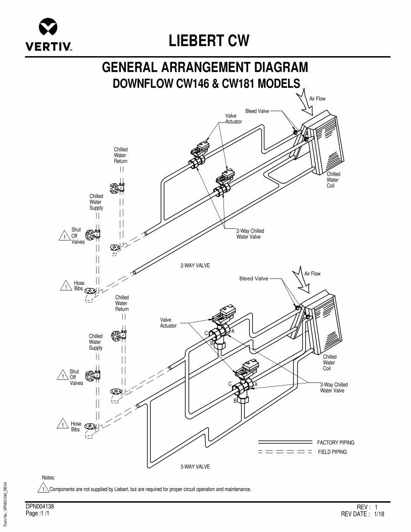
REV : 1REV DATE : 1/18
DPN004138Page :1 /1
For
m N
o.: D
PN
0010
40_R
EV
4
GENERAL ARRANGEMENT DIAGRAM
LIEBERT CW
DOWNFLOW CW146 & CW181 MODELS
ChilledWaterReturn
ChilledWaterSupply
OffValves
Bibs
ValveActuator
Air Flow
ChilledWaterCoil
2-WAY VALVE
ChilledWaterSupply
ChilledWaterReturn
OffValves
Bibs
2-Way ChilledWater Valve
Air Flow
ChilledWaterCoil
FACTORY PIPING
FIELD PIPING
3-WAY VALVE
AC
B
AC
B
3-Way ChilledWater Valve
ValveActuator
Bleed Valve
Bleed Valve
Shut
Hose
Shut
Hose
Notes:
1. Components are not supplied by Liebert, but are required for proper circuit operation and maintenance.
1
1
1
1

REV : 0REV DATE : 2/18
DPN004562Page :1 /1
UPFLOW 038-084, 106-114 MODELS
For
m N
o.: D
PN
0010
40_R
EV
4
GENERAL ARRANGEMENT DIAGRAM
LIEBERT CW
ChilledWaterReturn
ChilledWaterSupply
ShutOffValves
HoseBibs
AB
BleedValve
3-WayChilledWaterValve
Air Flow
ChilledWaterCoil
3-WAY VALVE
ChilledWaterSupply
ChilledWaterReturn
ShutOffValves
HoseBibs
ValveActuator
2-WayChilledWaterValve
BleedValve
Air Flow
ChilledWaterCoil
FACTORY PIPING
FIELD PIPING
2-WAY VALVE
C
Notes:
1. Components are not supplied by Liebert, but are required for proper circuit operation and maintenance.
1
1
1
1
Valve Actuator

REV : 6REV DATE : 6/19
DPN002036Page :1 /1
DOWNFLOW MODELS CW038 & CW041 W/ EC FANS
For
m N
o.: D
PN
0010
40_R
EV
4
PRIMARY CONNECTION LOCATIONS
LIEBERT CW
FRONT VIEW
A A
FRONT OF UNITSECTION A-A
0X
Y
ALL DIMENSIONS FROM RIGHT REAR CORNER OF UNIT WITH PANELS ASSEMBLED
35"889mm
50"1270mm
CWP
HV
POINT DESCRIPTION X Y CONNECTION SIZE / OPENING
CONDENSATE DRAIN 3/4" (19mm) NPT Female
W/ OPTIONAL CONDENSATE PUMP 1/2" (13mm) O.D. Cu
HUM HUMIDIFIER SUPPLY LINE 34 9/16" (878mm) 31 3/8" (797mm) 1/4" (6mm) O.D. Cu
CHILLED WATER PIPING SLOT (CENTER) 43 7/16" (1104mm) 31 5/8" (803mm) 9"(229mm) X 2 1/2"(64mm)
CW038: 1 3/8"(32mm)
CW041: 1 5/8"(41mm)
HV HIGH VOLT ELECTRICAL CONNECTION 37 7/16" (951mm) 2 1/2" (64mm)
LV LOW VOLT ELECTRICAL CONNECTION 35 7/16" (900mm) 7/8" (22mm)
CWPSUPPLY & RETURN PIPING DIAMETER
31 5/8" (803mm)
CD 35 1/16" (891mm) 29 5/16" (745mm)
N/A
HUM
LV
CD
Notes:1. Drawing not to scale. Tolerance on all piping dimensions is ± (13mm) 1/2".
2. Field pitch Condensate Drain line a minimum of 1/8" (3.2 mm) per foot (305 mm). All units contain a factory installed condensate trap. Do not trap external to the unit. Select appropriate drain system materials. The drain line must comply with all local codes.
3. Optional Condensate Pump to be installed under unit.
2
3
BlowerOutlet

REV : 5REV DATE : 6/19
DPN002035Page :1 /1
DOWNFLOW MODELS CW051 & CW060 W/ EC FANS
For
m N
o.: D
PN
0010
40_R
EV
4
PRIMARY CONNECTION LOCATIONS
LIEBERT CW
FRONT VIEW
A A
FRONT OF UNITSECTION A-A
X
Y
ALL DIMENSIONS FROM RIGHT REAR CORNER OF UNIT WITH PANELS ASSEMBLED
0
CD
LV
HVCWP
35"889mm
74"1880mm
POINT DESCRIPTION X Y CONNECTION SIZE / OPENING
CONDENSATE DRAIN 3/4" (19mm) NPT Female
W/OPTIONAL CONDENSATE PUMP 1/2" (13mm) O.D. Cu
HUM HUMIDIFIER SUPPLY LINE 58 3/8" (1484mm) 31 7/16" (799mm) 1/4" (6mm) O.D. Cu
CHILLED WATER PIPING SLOT (CENTER) 66 1/2" (1690mm) 31 1/4" (794mm) 11"(279mm) X 3"(76mm)
CW051: 1 5/8" (41mm)
CW060: 2 1/8" (54mm)
HV HIGH VOLT ELECTRICAL CONNECTION 59 1/2" (1512mm) 29 3/4" (756mm) 3" (76mm)
LV LOW VOLT ELECTRICAL CONNECTION 59 1/2" (1512mm) 32" (813mm) 7/8" (22mm)
CD 61" (1550mm) 27 3/4" (705mm)
CWPSUPPLY & RETURN PIPING DIAMETER - -
HUM
Notes:1. Drawing not to scale. Tolerance on all piping dimensions is ± (13mm) 1/2".
2. Field pitch Condensate Drain line a minimum of 1/8" (3.2 mm) per foot (305 mm). All units contain a factory installed condensate trap. Do not trap external to the unit. Select appropriate drain system materials. The drain line must comply with all local codes.
3. Optional Condensate Pump to be installed under unit.
2
3
BlowerOutlet
BlowerOutlet

REV : 5REV DATE : 6/19
DPN002034Page :1 /1
DOWNFLOW MODELS CW076 & CW084 W/ EC FANS
For
m N
o.: D
PN
0010
40_R
EV
4
PRIMARY CONNECTION LOCATIONS
LIEBERT CW
FRONT VIEWA A
35"889mm
99"2514mm
FRONT OF UNITSECTION A-A
CD
HUM
CWP
HV LV
0X
Y
ALL DIMENSIONS FROMREAR CORNER OF UNIT
INCLUDING PANELS
POINT DESCRIPTION X Y CONNECTION SIZE / OPENING
CONDENSATE DRAIN 76 3/8" (1940mm) 30 7/8" (784mm) 3/4" (19mm) NPT Female
W/OPTIONAL CONDENSATE PUMP 76 3/8" (1940mm) 30 7/8" (784mm) 1/2" (13mm) O.D. Cu
HUM HUMIDIFIER SUPPLY LINE 73 7/16" (1865mm) 31 7/16" (799mm) 1/4" (6mm) O.D. Cu
CHILLED WATER PIPING SLOT (CENTER) 91 3/8" (2321mm) 31 3/8" (797mm) 101 5/16"(277mm) X 2 15/16"(74mm)
SUPPY & RETURN PIPING DIAMETER - - 2 1/8" (54mm)
HV HIGH VOLT ELECTRICAL CONNECTION 83 7/8" (2130mm) 30 7/8" (784mm) 3" (76mm)
LV LOW VOLT ELECTRICAL CONNECTION 81 3/8" (2067mm) 31 7/16" (799mm) 7/8" (22mm)
CD
CWP
Notes:1. Drawing not to scale. Tolerance on all piping dimensions is ± (13mm) 1/2".
2. Field pitch Condensate Drain line a minimum of 1/8" (3.2 mm) per foot (305 mm). All units contain a factory installed condensate trap. Do not trap external to the unit. Select appropriate drain system materials. The drain line must comply with all local codes.
2
BlowerOutlet
BlowerOutlet

REV : 9REV DATE : 6/19
DPN001628Page :1 /1
DOWNFLOW CW106 & CW114 W/EC FANS MODELS
For
m N
o.: D
PN
0010
40_R
EV
4
PRIMARY CONNECTION LOCATIONS
LIEBERT CW
FRONT OF UNIT
FRONT VIEW
SECTION A-A
ALL DIMENSIONS FROMREAR CORNER OF UNITINCLUDING PANELS
A A
POINT DESCRIPTION X Y CONNECTION SIZE / OPENING
CONDENSATE DRAIN 103-1/2" (2629mm) 28" (711mm) 1-1/4" NPT Female
W/ OPTIONAL PUMP 103-1/2" (2629mm) 28" (711mm) 1/2" O.D. Cu
HUM HUMIDIFIER SUPPLY LINE 107-1/2" (2731mm) 29" (737mm) 1/4" O.D. Cu
CWS 2 2-WAY CHILLED WATER SUPPLY 118-1/2" (3010mm) 31" (787mm) CW106: 2-1/8"; CW114: 2-5/8"
CWS 3 3-WAY CHILLED WATER SUPPLY 115-1/2" (2934mm) 31" (787mm) CW106: 2-1/8"; CW114: 2-5/8"
CWR 2 2-WAY CHILLED WATER RETURN 112-1/2" (2858mm) 31" (787mm) CW106: 2-1/8"; CW114: 2-5/8"
CWR 3 3-WAY CHILLED WATER RETURN 115-1/2" (2934mm) 22" (559mm) CW106: 2-1/8"; CW114: 2-5/8"
E1 ELECTRICAL CONN. (HIGH VOLT) 35" (889mm) 31" (787mm) 2"
E2 ELECTRICAL CONN. (HIGH VOLT) 34" (864mm) 29" (737mm) 2"
LV1 ELECTRICAL CONN. (LOW VOLT) 35.5" (902mm) 26-1/2" (673mm) 1-3/8"
LV2 ELECTRICAL CONN. (LOW VOLT) 33.5" (851mm) 26-1/2" (673mm) 1-3/8"
CD
122"3099mm
35"889mm
CWS 2
CWS 3
Y
XO
LV1 LV2
E1E2
HUM
CD
CWR 2
CWR 3
Notes:1. Drawing not to scale. Tolerance on all piping dimensions is ± (13mm) 1/2".
2. Field pitch Condensate Drain line a minimum of 1/8" (3.2 mm) per foot (305 mm). All units contain a factory installed condensate trap. Do not trap external to the unit. Select appropriate drain system materials. The drain line must comply with all local codes.
2
BlowerOutlet
BlowerOutlet
BlowerOutlet

REV : 5REV DATE : 6/19
DPN001693Page :1 /1
CW146 & CW181 DOWNFLOW MODELS W/ EC FANS
For
m N
o.: D
PN
0010
40_R
EV
4
PRIMARY CONNECTION LOCATIONS
LIEBERT CW
FRONT OF UNIT
FRONT VIEW
SECTION A-A
ALL DIMENSIONS FROMREAR CORNER OF UNITINCLUDING PANELS
E2
HUM
CDLV1LV2
O
X
Y
A A
CWS
CWR
47"1194mm
122"3099mm
LV3
E1
POINT DESCRIPTION X Y CONNECTION SIZE / OPENING
CONDENSATE DRAIN 110" (2794mm) 35" (889mm) 1-1/4" NPT Female
W/ OPTIONAL PUMP 110" (2794mm) 35" (889mm) 1/2" O.D. Cu
HUM HUMIDIFIER SUPPLY LINE 101" (2565mm) 43" (1092mm) 1/4" O.D. Cu
2-WAY CHILLED WATER SUPPLY 117" (2972mm) 37" (940mm) 3-1/8"
3-WAY CHILLED WATER SUPPLY 117" (2972mm) 37" (940mm) 3-1/8"
2-WAY CHILLED WATER RETURN 117" (2972mm) 30" (762mm) 3-1/8"
3-WAY CHILLED WATER RETURN 117" (2972mm) 30" (762mm) 3-1/8"
E1 ELECTRICAL CONN. (HIGH VOLT) 113" (2870mm) 43" (1092mm) 2"
E2 ELECTRICAL CONN. (HIGH VOLT) 110" (2794mm) 43" (1092mm) 2"
LV1 ELECTRICAL CONN. (LOW VOLT) 2-1/2" (64mm) 36" (914mm) 7/8"
LV2 ELECTRICAL CONN. (LOW VOLT) 2-1/2" (64mm) 37-1/2" (953mm) 7/8"
LV3 ELECTRICAL CONN. (LOW VOLT) 2-1/2" (64mm) 39" (991mm) 7/8"
CD
CWS
CWR
*
Notes:1. Drawing not to scale. Tolerance on all piping dimensions is ± (13mm) 1/2".
2. Field pitch Condensate Drain line a minimum of 1/8" (3.2 mm) per foot (305 mm). All units contain a factory installed condensate trap. Do not trap external to the unit. Select appropriate drain system materials. The drain line must comply with all local codes.
2
BlowerOutlet
BlowerOutlet
BlowerOutlet

REV : 4REV DATE : 6/17
DPN001668Page :1 /1
CW038 - CW084 UPFLOW MODELS W/ FORWARD CURVED BLOWERS
For
m N
o.: D
PN
0010
40_R
EV
4
UNIT PIPING CONNECTION LOCATIONS
LIEBERT CW
OPTIONAL STEAM REHEATOPTIONAL HOT WATER REHEAT(3-WAY VALVE)
HOT WATER REHEAT COIL
ACTUATOR
RETURN
SUPPLY
Y-STRAINERSTEAM REHEAT COIL
ACTUATORSUPPLY
Y-STRAINERRETURN
STEAM TRAP
OPTIONAL PLENUM REHEAT SCHEMATICS
C - Steam Reheat Supply Line.
F - Hot Water Reheat Return Line.
E - Steam Reheat Return Line(Field install factory supplied steam trap with vacuum breaker).
D - Hot Water Reheat Supply Line.
NOTE: Install all piping per local codes.
PLENUM LEFTEND PANEL
PLENUM FIELD PIPING LOCATIONSFor separate steam or hot water plenum in UPFLOW units, pipingmay exit through bottom, top or sides by fieldcutting an opening in a suitable location. Steam or hot water plenumpiping connections are located at the left side of the plenum.
UNIT FIELD PIPING LOCATIONSPiping stubbed out inside unit end compartment for fieldconnection through 2 5/8" x 10 3/4" (66 x 273mm)opening as shown. Piping may also exit through bottom or top ofend compartment by field cutting an opening in a suitable location(except bottom return air units).
A - Chilled Water Supply Line. (Line is stubbed down, field install elbow for side connection).
B - Chilled Water Return Line. (Line is stubbed down, field install elbow for side connection).
1/4" OD CU Humidifier WaterSupply Line.
Piping outlet location on unitsw/rear return option.
UNIT LEFTEND PANEL
Condensate Drain. Field pitch a min. of1/8" (3mm) per ft. (305mm). 3/4" NPTfor units without factory installedcondensate pump. Do not install an external trap.1/2" OD CU for units with factory installed condensate pump.
CW038 1 3/8 1 3/8
CW041
CW051
CW060
CW076
CW084
Factory Provided Piping Connection Sizes in.
1 5/8
2 1/8
1 5/8
2 1/8
A
OD CU
B
OD CU
C
NPT FEMALE
D
OD CU
E
NPT FEMALE
1/2 5/8
MODELS
3/4 7/8
1/2 5/8
3/4 7/8
F
OD CU
1"25mm
Rear Panel
1 1/32"26mm
2 5/8"67mm
10 3/4"273mm
7 1/2"190mm
OPTIONAL HOT WATER REHEAT(2-WAY VALVE)
RETURN
ACTUATOR
SUPPLY
Y-STRAINER HOT WATER REHEAT COIL

REV : 2REV DATE : 1/17
DPN001669Page :1 /1
CW106 & CW114 UPFLOW MODELS
For
m N
o.: D
PN
0010
40_R
EV
4
UNIT PIPING CONNECTION LOCATIONS
LIEBERT CW
NOTE: Install all piping per local codes.
UNIT FIELD PIPING LOCATIONS
Piping stubbed out inside unit end compartment for fieldconnection through 13" x 6-1/2" (330 x 165mm) opening asshown. Piping may also exit through bottom of endcompartment by field cutting an opening in a suitablelocation.
A - Chilled Water Supply Line. 2-5/8" O.D. CU on 3 wayfront return units only.
1/4" OD CU Humidifier WaterSupply Line.
UNIT LEFTEND PANEL
1" (25mm) REAR PANEL Condensate Drain. Field pitch a min. of1/8" (3mm) per ft. (305mm). 1-1/4" NPT for units withouta factory installed condensate pump. 1/2" OD CU forunits with factory installed condensate pump. Do notinstall an external trap.
B - Chilled Water Return Line. 2-5/8" O.D. CU
3"76mm
7 1/2"190mm
13"330mm
A- Chilled Water Supply Line2-5/8" O.D. CU on all unitsexcept 3 way front return.
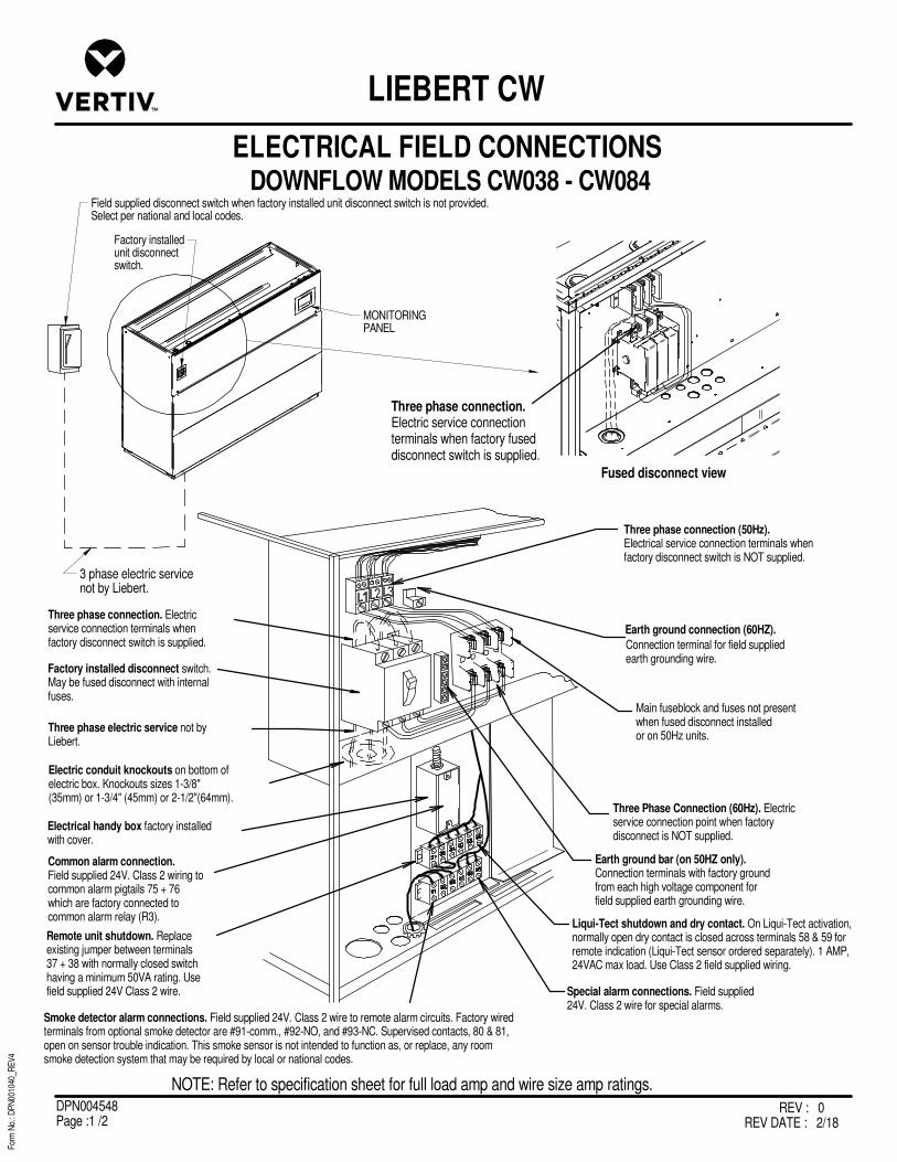
REV : 0REV DATE : 2/18
DPN004548Page :1 /2
For
m N
o.: D
PN
0010
40_R
EV
4
ELECTRICAL FIELD CONNECTIONS
LIEBERT CW
NOTE: Refer to specification sheet for full load amp and wire size amp ratings.
2 3
Three phase connection (50Hz).Electrical service connection terminals whenfactory disconnect switch is NOT supplied.
Earth ground bar (on 50HZ only).Connection terminals with factory groundfrom each high voltage component forfield supplied earth grounding wire.
Special alarm connections. Field supplied24V. Class 2 wire for special alarms.
Smoke detector alarm connections. Field supplied 24V. Class 2 wire to remote alarm circuits. Factory wiredterminals from optional smoke detector are #91-comm., #92-NO, and #93-NC. Supervised contacts, 80 & 81,open on sensor trouble indication. This smoke sensor is not intended to function as, or replace, any roomsmoke detection system that may be required by local or national codes.
Three phase connection. Electricservice connection terminals whenfactory disconnect switch is supplied.
Factory installed disconnect switch.May be fused disconnect with internalfuses.
Three phase electric service not byLiebert.
Electric conduit knockouts on bottom ofelectric box. Knockouts sizes 1-3/8"(35mm) or 1-3/4" (45mm) or 2-1/2"(64mm).
Electrical handy box factory installedwith cover.
Common alarm connection.Field supplied 24V. Class 2 wiring tocommon alarm pigtails 75 + 76which are factory connected tocommon alarm relay (R3).
Remote unit shutdown. Replaceexisting jumper between terminals37 + 38 with normally closed switchhaving a minimum 50VA rating. Usefield supplied 24V Class 2 wire.
Three Phase Connection (60Hz). Electricservice connection point when factorydisconnect is NOT supplied.
Three phase connection.Electric service connectionterminals when factory fuseddisconnect switch is supplied.
Fused disconnect view
Main fuseblock and fuses not presentwhen fused disconnect installedor on 50Hz units.
3 phase electric servicenot by Liebert.
MONITORINGPANEL
Field supplied disconnect switch when factory installed unit disconnect switch is not provided.Select per national and local codes.
Factory installedunit disconnectswitch.
DOWNFLOW MODELS CW038 - CW084
Liqui-Tect shutdown and dry contact. On Liqui-Tect activation,normally open dry contact is closed across terminals 58 & 59 forremote indication (Liqui-Tect sensor ordered separately). 1 AMP,24VAC max load. Use Class 2 field supplied wiring.
Earth ground connection (60HZ).
Connection terminal for field suppliedearth grounding wire.

REV : 0REV DATE : 2/18
DPN004548Page :2 /2
For
m N
o.: D
PN
0010
40_R
EV
4
ELECTRICAL FIELD CONNECTIONS
LIEBERT CW
Top Entrance
Electric Box Bottom
Coil Support Frame
Unit Bottom Bottom Entrance
Remove knockouts.
Low Voltage Communication WiringCAT5E Ethernet connections – field installedAvoid routing near high voltage wiring.Secure wiring to prevent damage anduse bushing or edge guard to avoid sharp edges.
Remove knockouts to access control board.
P64
1. To provide unit to unit (U2U) networking, the customer must first connect an Ethernet cable from P64 on the iCOM control board, to a network switch.
Notes:
1
1
MONITORINGPANEL
Front of Unit Right side of Unit
DOWNFLOW MODELS CW038 - CW084FOR NETWORK ETHERNET CONNECTIONS
NOTE: Refer to specification sheet for full load amp and wire size amp ratings.
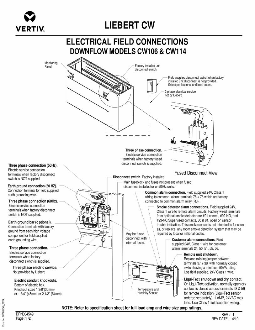
DOWNFLOW MODELS CW106 & CW114
For
m N
o.: D
PN
0010
40_R
EV
4
ELECTRICAL FIELD CONNECTIONS
LIEBERT CW
REV : 1REV DATE : 4/19
DPN004549Page :1 /2
Temperature andHumidity Sensor
Earth ground bar (optional).Connection terminals with factoryground from each high voltagecomponent for field suppliedearth grounding wire.
Electric conduit knockouts.Bottom of electric box.Knockout sizes 1 3/8"(35mm)or 1 3/4" (45mm) or 2 1/2" (64mm).
Three phase electric service.Not provided by Liebert.
Three phase connection.Electric service connectionterminals when factorydisconnect switch is supplied.
Disconnect switch. Factory installed.
Earth ground connection (60 HZ).Connection terminal for field suppliedearth grounding wire.
Three phase connection (60Hz).Electric service connectionterminals when factory disconnectswitch is NOT supplied.
Common alarm connection. Field supplied 24V, Class 1wiring to common alarm terminals 75 + 76 which are factoryconnected to common alarm relay (R3).
Smoke detector alarm connections. Field supplied 24V,Class 1 wire to remote alarm circuits. Factory wired terminalsfrom optional smoke detector are #91-comm., #92-NO, and#93-NC.Supervised contacts, 80 & 81, open on sensortrouble indication. This smoke sensor is not intended to functionas, or replace, any room smoke detection system that may berequired by local or national codes.
Customer alarm connections. Fieldsupplied 24V, Class 1 wire for customeralarm terminals 24, 50, 51, 55, 56.
Remote unit shutdown.Replace existing jumper betweenterminals 37 + 38 with normally closedswitch having a minimum 50VA rating.Use field supplied, 24V Class 1 wire.
May be fuseddisconnect withinternal fuses.
Fused Disconnect View
Three phase connection.Electric service connection
terminals when factory fuseddisconnect switch is supplied.
Main fuseblock and fuses not present when fuseddisconnect installed or on 50Hz units.
Three phase connection (50Hz).Electric service connectionterminals when factory disconnectswitch is NOT supplied.
MonitoringPanel
Field supplied disconnect switch when factoryinstalled unit disconnect is not provided.Select per National and local codes.
3 phase electrical servicenot by Liebert.
Factory installed unitdisconnect switch.
Liqui-Tect shutdown and dry contact.On Liqui-Tect activation, normally open drycontact is closed across terminals 58 & 59for remote indication (Liqui-Tect sensorordered separately). 1 AMP, 24VAC maxload. Use Class 1 field supplied wiring.
NOTE: Refer to specification sheet for full load amp and wire size amp ratings.

DOWNFLOW MODELS CW106 & CW114
For
m N
o.: D
PN
0010
40_R
EV
4
ELECTRICAL FIELD CONNECTIONS
LIEBERT CW
REV : 1REV DATE : 4/19
DPN004549Page :2 /2
NOTE: Refer to specification sheet for full load amp and wire size amp ratings.
Low Voltage Communication Wiring
CAT5E Ethernet connections – field installedAvoid routing near high voltage wiring.Secure wiring to prevent damage anduse bushing or edge guard to avoid sharp edges.
Remove knockouts to access control board.
Top Entrance
Electric Box Bottom
Coil Support Frame
Unit Bottom
Bottom Entrance
Monitoring Panel
1. To provide unit to unit (U2U) networking, the customer must first connect an Ethernet cable from P64 on the iCOM control board, to a network switch.
Notes:
1
1
Remove knockout to access control board.
Remove knockout
P64
Wire routing from the top of the unit
Wire routing from the bottom of the unit

DOWNFLOW CW146 & CW181 MODELS W/ EC FANS
ELECTRICAL FIELD CONNECTIONS DEFINITIONS & LOCATIONS
LIEBERT CW
For
m N
o.: D
PN
0010
40_R
EV
4
REV : 1REV DATE : 12/18
DPN004550Page :1 /3
STANDARD ELECTRICAL CONNECTIONS
1) Primary high voltage entrance - 2.50” (64mm); 1.75” (44mm); 1.375” (35mm) diameter concentric knockouts located in bottom of box.
2) Primary low voltage entrance - Quantity (3) 1.125” (28mm) diameter knockouts located in bottom of box.
3) Three phase electrical service - Terminals are on main fuse block (disregard if unit has optional disconnect switch). Three phase service not by Liebert.
4) Earth ground - Terminal for field supplied earth grounding wire.
5) Remote unit shutdown - Replace existing jumper between terminals 37 & 38 with field supplied normally closed switch having a minimum 75VA, 24VAC rating. Use field supplied Class 1 wiring.
6) Customer alarm inputs - Terminals for field supplied, normally open contacts, having a minimum 75VA, 24VAC rating, between terminals 24 & 50, 51, 55, 56. Use field supplied Class 1 wiring. Terminal availability varies by unit options.
7) Common alarm - On any alarm, normally open dry contact is closed across terminals 75 & 76 for remote indication. 1 AMP, 24VAC max load. Use Class 1 field supplied wiring.
8) Unit factory installed disconnect switch, Fuse Block and Main Fuses – Type of disconnect switch available – “Locking”. The “Locking Type” consists of a non-automatic molded case switch operational from the outside of the unit. Access to the high voltage electric panel compartment can be obtained only with the switch in the “off” position. The molded case switch disconnect models contain separate main fuses. Units with fused disconnect have main fuses within the disconnect.
OPTIONAL ELECTRICAL CONNECTIONS
9) Secondary disconnect switch and earth ground – Fuses are included in the 65KAIC SCCR fused disconnect switch models.
10) Three phase electrical service - Terminals are on top of disconnect switch. Three phase service not by Liebert.
11) Smoke sensor alarm - Factory wired dry contacts from smoke sensor are 91-common, 92-NO, and 93-NC. Supervised contacts, 80 & 81, open on sensor trouble indication. This smoke sensor is not intended to function as, or replace, any room smoke detection system that may be required by local or national codes. 1 AMP, 24VAC max load. Use Class 1 field supplied wiring.
12) Reheat and humidifier lockout - Remote 24VAC required at terminals 82 & 83 for lockout of reheat and humidifier.
13) Condensate alarm (with condensate pump option) - On pump high water indication, normally open dry contact is closed across terminals 88 & 89 for remote indication. 1 AMP, 24VAC max load. Use Class 1 field supplied wiring.
14) Remote humidifier - On any call for humidification, normally open dry contact is closed across terminals 11 & 12 to signal field supplied remote humidifier. 1 AMP, 24VAC max load. Use Class 1 field supplied wiring.
15) Reversing Starter Power Supply Notification – Normally open contact terminals 106 and 107 will close when Power Supply 1 is engaged; 110 and 111 will close when Power Supply 2 is engaged.
OPTIONAL LOW VOLTAGE TERMINAL PACKAGE CONNECTIONS
16) Remote unit shutdown - Two additional contact pairs available for unit shutdown (labeled as 37B & 38B, 37C & 38C). Replace jumpers with field supplied normally closed switch having a minimum 75VA, 24VAC rating. Use field supplied Class 1 wiring.
17) Common alarm - On any alarm, two additional normally open dry contacts are closed across terminals 94 & 95 and 96 & 97 for remote indication. 1 AMP, 24VAC max load. Use Class 1 field supplied wiring.
18) Main fan auxiliary switch - On closure of main fan contactor, normally open dry contact is closed across terminals 84 & 85 for remote indication. 1 AMP, 24VAC max load. Use Class 1 field supplied wiring.
19) Liqui-Tect shutdown and dry contact - On Liqui-Tect activation, normally open dry contact is closed across terminals 58 & 59 for
remote indication (Liqui-Tect sensor ordered separately). 1 AMP, 24VAC max load. Use Class 1 field supplied wiring.
OPTIONAL COMMUNCATION CONNECTIONS
20) Unit-To-Unit - Plug 64 is reserved for U2U communication.
21) Site and BMS - Plug 74 and terminal block 3 are reserved for Site and BMS connections. Plug 74
is an eight pin RJ45 for a Cat 5 cable. Terminal block 3 is a two position screw terminal block for use with twisted pair wires.

DOWNFLOW CW146 & CW181 MODELS W/ EC FANS
ELECTRICAL FIELD CONNECTIONS DEFINITIONS & LOCATIONS
LIEBERT CW
For
m N
o.: D
PN
0010
40_R
EV
4
REV : 1REV DATE : 12/18
DPN004550Page :2 /3
Note: Refer to DPN001699 SHT. 1 of 4 for descriptions of numbered callouts.
A
B
C
D
Note: Typical orientation of components shown. Component location varies by option and unit.
37C 38C 37B 38B 37 38
24 50 51 55 56 11 12
58 59 84 85 94 95 96 97 75 76
91 92 93 80 81 82 83
88 89
106 107 110 111
4 Ground Lug
Disconnect
8
1
Field High VoltageEntrance
Main Fuses
3 GroundCurrentDetector
4 50Hz
ReheatContactors
BackupReheatContactor
HumidifierContactor
Main FanContactor
T1 Transformer
CPARRelay
RemoteHumidifierRelay
LiquitectShutdownRelay
R3Relay
Smoke DetectorPower Supply
iCOMFuse Board
2
ABC
DTerminals forField Low VoltageWiring Connections(See below forcallouts)
Large iCOMI/O Board
Filter ClogSwitch
High TempStat
EM1Relay
T6 Transformer
Power Block
Control Fuses
Main FanFuses
Fan Transformer Fuses(B) Voltage only
Humidifier Fuses
ReheatFuses
CondensatePump Fuses
Cover Plate/Reversing StarterLocation
PowerBlock
15 11 12
19
6
18 17 7
14
13 16 5
Electrical Panel Layout 60Hz
20 Plug P64
21 Plug P74
21 Terminal Block TB3
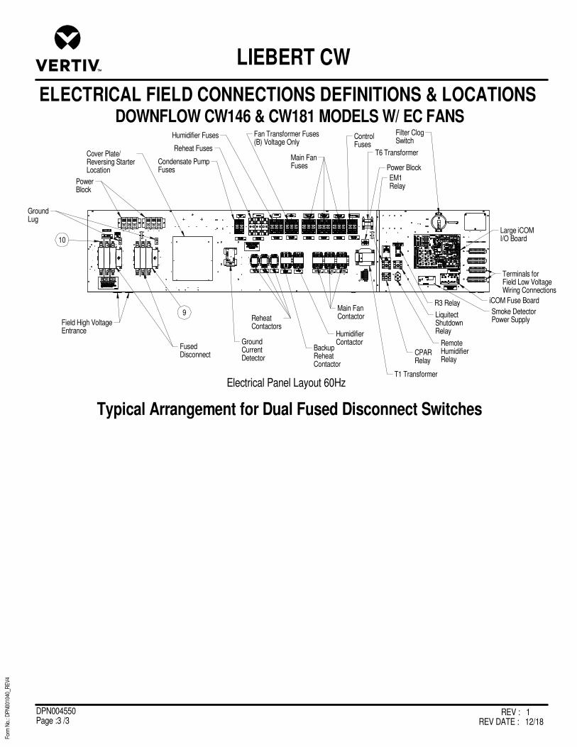
DOWNFLOW CW146 & CW181 MODELS W/ EC FANS
ELECTRICAL FIELD CONNECTIONS DEFINITIONS & LOCATIONS
LIEBERT CW
For
m N
o.: D
PN
0010
40_R
EV
4
REV : 1REV DATE : 12/18
DPN004550Page :3 /3
Electrical Panel Layout 60Hz
Typical Arrangement for Dual Fused Disconnect Switches
10
Cover Plate/Reversing StarterLocation
Condensate PumpFuses
Humidifier Fuses Fan Transformer Fuses(B) Voltage Only
T6 Transformer
EM1Relay
Filter ClogSwitch
LiquitectShutdownRelay
RemoteHumidifierRelay
HumidifierContactor
BackupReheatContactor
ReheatContactors
GroundCurrentDetector
FusedDisconnect
9
Field High VoltageEntrance
GroundLug
PowerBlock
Reheat FusesMain FanFuses
ControlFuses
Power Block
T1 Transformer
Main FanContactor
CPARRelay
R3 RelaySmoke DetectorPower Supply
iCOM Fuse Board
Large iCOMI/O Board
Terminals forField Low VoltageWiring Connections
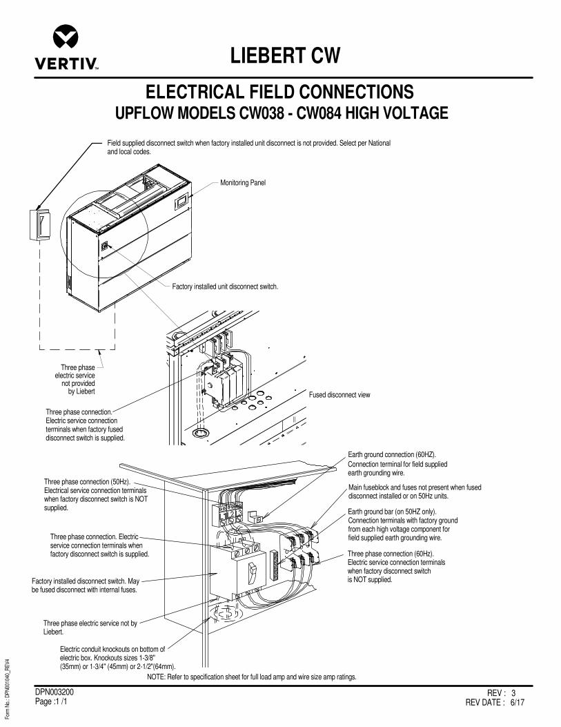
REV : 3REV DATE : 6/17
DPN003200Page :1 /1
UPFLOW MODELS CW038 - CW084 HIGH VOLTAGE
For
m N
o.: D
PN
0010
40_R
EV
4
ELECTRICAL FIELD CONNECTIONS
LIEBERT CW
2 3
Three phase connection (50Hz).Electrical service connection terminalswhen factory disconnect switch is NOTsupplied.
Earth ground connection (60HZ).
Connection terminal for field suppliedearth grounding wire.
Earth ground bar (on 50HZ only).Connection terminals with factory groundfrom each high voltage component forfield supplied earth grounding wire.
Three phase connection (60Hz).Electric service connection terminalswhen factory disconnect switchis NOT supplied.
Three phase connection. Electricservice connection terminals whenfactory disconnect switch is supplied.
Factory installed disconnect switch. Maybe fused disconnect with internal fuses.
Three phase electric service not byLiebert.
Electric conduit knockouts on bottom ofelectric box. Knockouts sizes 1-3/8"(35mm) or 1-3/4" (45mm) or 2-1/2"(64mm).
Three phase connection.Electric service connectionterminals when factory fuseddisconnect switch is supplied.
Fused disconnect view
Main fuseblock and fuses not present when fuseddisconnect installed or on 50Hz units.
Field supplied disconnect switch when factory installed unit disconnect is not provided. Select per Nationaland local codes.
NOTE: Refer to specification sheet for full load amp and wire size amp ratings.
Factory installed unit disconnect switch.
Monitoring Panel
Three phaseelectric service
not providedby Liebert
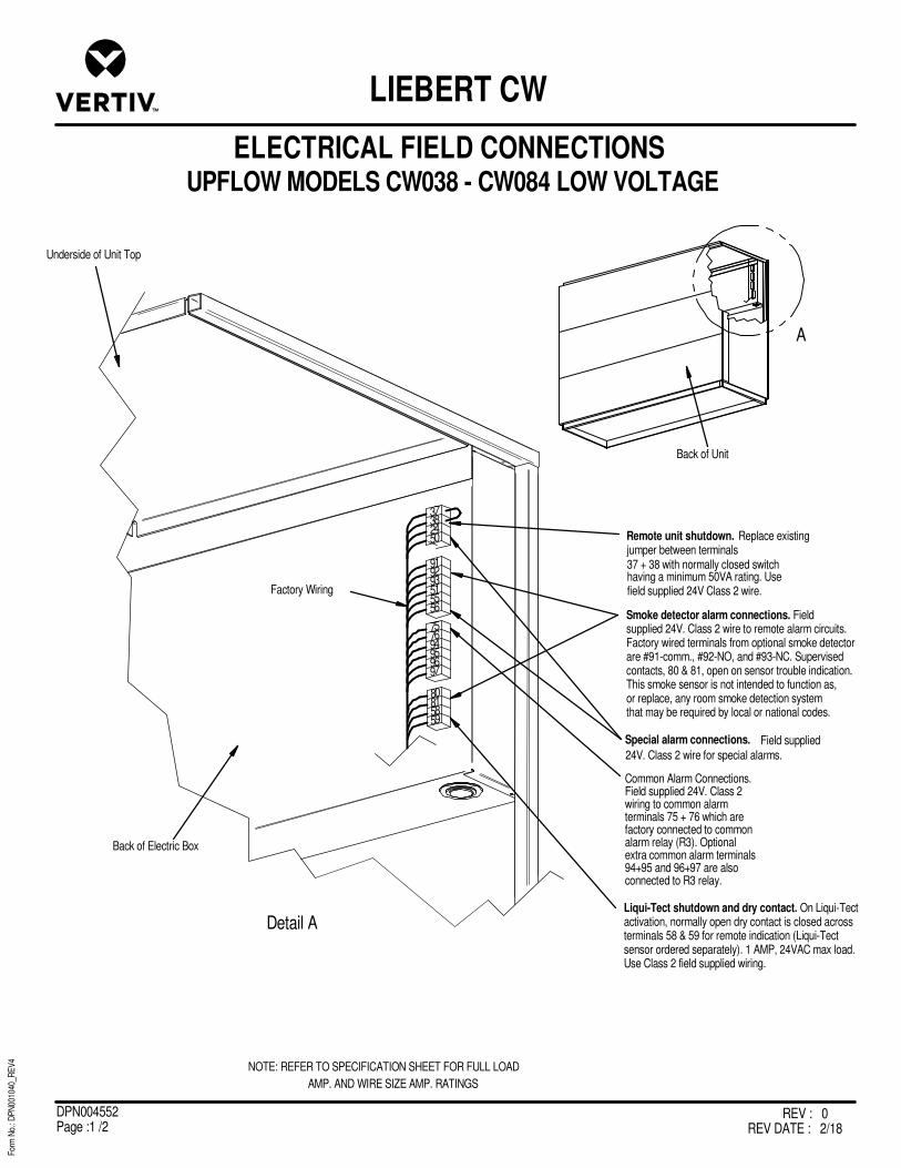
UPFLOW MODELS CW038 - CW084 LOW VOLTAGE
ELECTRICAL FIELD CONNECTIONS
LIEBERT CW
For
m N
o.: D
PN
0010
40_R
EV
4
REV : 0REV DATE : 2/18
DPN004552Page :1 /2
NOTE: REFER TO SPECIFICATION SHEET FOR FULL LOAD
AMP. AND WIRE SIZE AMP. RATINGS
Factory Wiring
Back of Electric Box
Back of Unit
Underside of Unit Top
Common Alarm Connections.Field supplied 24V. Class 2wiring to common alarmterminals 75 + 76 which arefactory connected to commonalarm relay (R3). Optionalextra common alarm terminals94+95 and 96+97 are also connected to R3 relay.
24V. Class 2 wire for special alarms.
Field suppliedSpecial alarm connections.
Remote unit shutdown.
field supplied 24V Class 2 wire.having a minimum 50VA rating. Use37 + 38 with normally closed switchjumper between terminals
Replace existing
A
Detail A
37382450
919293515556
757694959697
80815859
Smoke detector alarm connections. Fieldsupplied 24V. Class 2 wire to remote alarm circuits.Factory wired terminals from optional smoke detectorare #91-comm., #92-NO, and #93-NC. Supervisedcontacts, 80 & 81, open on sensor trouble indication.This smoke sensor is not intended to function as,or replace, any room smoke detection systemthat may be required by local or national codes.
Liqui-Tect shutdown and dry contact. On Liqui-Tectactivation, normally open dry contact is closed acrossterminals 58 & 59 for remote indication (Liqui-Tectsensor ordered separately). 1 AMP, 24VAC max load.Use Class 2 field supplied wiring.
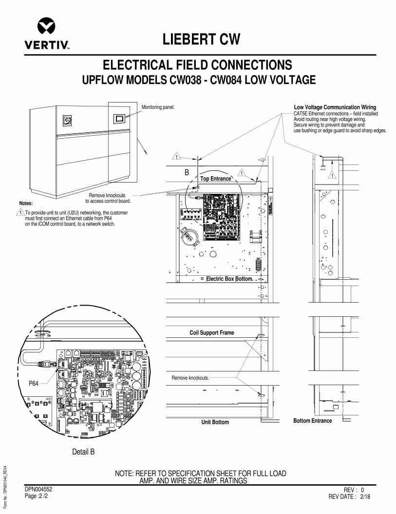
UPFLOW MODELS CW038 - CW084 LOW VOLTAGE
ELECTRICAL FIELD CONNECTIONS
LIEBERT CW
For
m N
o.: D
PN
0010
40_R
EV
4
REV : 0REV DATE : 2/18
DPN004552Page :2 /2
Low Voltage Communication WiringMonitoring panel.
Remove knockouts.
CAT5E Ethernet connections – field installedAvoid routing near high voltage wiring.Secure wiring to prevent damage anduse bushing or edge guard to avoid sharp edges.
Remove knockouts to access control board.
Top Entrance
Electric Box Bottom
Coil Support Frame
Unit Bottom Bottom Entrance
1
11
NOTE: REFER TO SPECIFICATION SHEET FOR FULL LOADAMP. AND WIRE SIZE AMP. RATINGS
1. To provide unit to unit (U2U) networking, the customer must first connect an Ethernet cable from P64 on the iCOM control board, to a network switch.
Notes:
B
P64
Detail B

REV : 4REV DATE : 4/19
DPN003202Page :1 /1
UPFLOW MODELS CW106 - CW114 HIGH VOLTAGE
For
m N
o.: D
PN
0010
40_R
EV
4
ELECTRICAL FIELD CONNECTIONS
LIEBERT CW
2 3
Field supplied disconnect switch when factory installed unit disconnect is not provided. Selectper National and local codes.
Factory installed unit disconnect switch.
Monitoring panel.
Three phase electric service not byLiebert.
Earth ground connection (60HZ).
Connection terminal for field suppliedearth grounding wire.
Earth ground bar (on 50HZ only).Connection terminals with factory groundfrom each high voltage component forfield supplied earth grounding wire.
Three phase connection (60Hz).Electric service connection terminals when factorydisconnect switch is NOT supplied.
Three phase connection. Electricservice connection terminals whenfactory disconnect switch is supplied.
Factory installed disconnect switch. Maybe fused disconnect with internal fuses.
Three phase electric servicenot by Liebert.
Electrical conduit knockoutsin top of electrical box.Knockout sizes 1-3/8" (35mm),1-3/4" (45mm) or 2-1/2" (64mm)
Three phase connection.Electric service connectionterminals when factory fuseddisconnect switch is supplied.
Fused disconnect view
Main fuseblock and fuses not present whenfused disconnect installed or on 50Hz units.
Three phase connection (50Hz).Electrical service connection terminalswhen factory disconnect switch is NOTsupplied.

UPFLOW MODELS CW106 & CW114 LOW VOLTAGE
ELECTRICAL FIELD CONNECTIONS
LIEBERT CW
For
m N
o.: D
PN
0010
40_R
EV
4
REV : 0REV DATE : 2/18
DPN004551Page :1 /2
Monitoring panel.
Knockout for low voltagewiring connections intop frame member.Knockout size 7/8" (22mm)
Disconnect Switch
Replace
field supplied 24V Class 1 wire.having a minimum 50VA rating. Use37 + 38 with normally closed switchexisting jumper between terminalsRemote unit shutdown.
alarms.supplied 24V. Class 1 wire for special
FieldSpecial alarm connections.
common alarm relay (R3).which are factory connected to
supplied 24V. Class 1 wiring toCommon alarm connection. Field
common alarm pigtails 75 + 76
NOTE: Refer to specification sheet for full load amp and wire size amp ratings.
Smoke detector alarm connections. Fieldsupplied 24V. Class 1 wire to remote alarm circuits.Factory wired terminals from optional smoke detectorare #91-comm., #92-NO, and #93-NC. Supervisedcontacts, 80 & 81, open on sensor trouble indication.This smoke sensor is not intended to function as,or replace, any room smoke detection systemthat may be required by local or national codes.
Liqui-Tect shutdown and dry contact. On Liqui-Tectactivation, normally open dry contact is closed acrossterminals 58 & 59 for remote indication (Liqui-Tectsensor ordered separately). 1 AMP, 24VAC max load.Use Class 2 field supplied wiring.
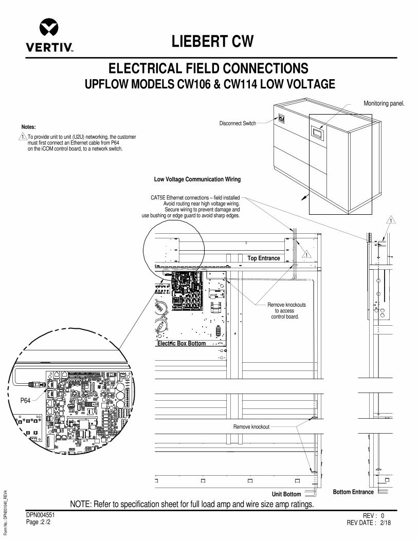
UPFLOW MODELS CW106 & CW114 LOW VOLTAGE
ELECTRICAL FIELD CONNECTIONS
LIEBERT CW
For
m N
o.: D
PN
0010
40_R
EV
4
REV : 0REV DATE : 2/18
DPN004551Page :2 /2
Monitoring panel.
Disconnect Switch
Remove knockouts to access control board.
Electric Box Bottom
Unit Bottom Bottom Entrance
Low Voltage Communication Wiring
CAT5E Ethernet connections – field installedAvoid routing near high voltage wiring.Secure wiring to prevent damage and
use bushing or edge guard to avoid sharp edges.
Remove knockout
1
1
1. To provide unit to unit (U2U) networking, the customer must first connect an Ethernet cable from P64 on the iCOM control board, to a network switch.
Notes:
P64
Top Entrance
NOTE: Refer to specification sheet for full load amp and wire size amp ratings.
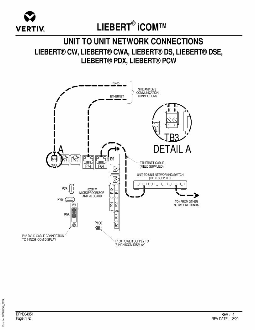
REV : 4REV DATE : 2/20
DPN004351Page :1 /2
For
m N
o.: D
PN
0010
40_R
EV
4
UNIT TO UNIT NETWORK CONNECTIONS
LIEBERT® iCOM™
LIEBERT® CW, LIEBERT® CWA, LIEBERT® DS, LIEBERT® DSE,LIEBERT® PDX, LIEBERT® PCW
TO / FROM OTHERNETWORKED UNITS
TB3
P71 P72
P74 P64
E5
P67
P66
P11
P12
P21
P20
P13
P7
P76
P95
P100
P75
2
RS485
ETHERNET
SITE AND BMS COMMUNICATION
CONNECTIONS
iCOM™MICROPROCESSOR
AND I/O BOARD
ETHERNET CABLE(FIELD SUPPLIED)
TB3
P
2DETAIL A
-
1 2
A
UNIT-TO-UNIT NETWORKING SWITCH(FIELD SUPPLIED)
+
P95 DVI-D CABLE CONNECTIONTO 7-INCH ICOM DISPLAY P100 POWER SUPPLY TO
7-INCH ICOM DISPLAY

REV : 4REV DATE : 2/20
DPN004351Page :2 /2
For
m N
o.: D
PN
0010
40_R
EV
4
UNIT TO UNIT NETWORK CONNECTIONS
LIEBERT® iCOM™
LIEBERT® CW, LIEBERT® CWA, LIEBERT® DS, LIEBERT® DSE,LIEBERT® PDX, LIEBERT® PCW
ETHERNET CABLE(FIELD SUPPLIED)
TB3
P71 P72
P74 P64
E5
P67
P66
P11
P12
P21
P20
P13
P7
P76
P95
P100
P75
2
iCOM™MICROPROCESSOR
AND I/O BOARD
TB3
P71 P72
P74 P64
E5
P67
P66
P11
P12
P21
P20
P13
P7
P76
P95
P100
P75
2
iCOM™MICROPROCESSOR
AND I/O BOARD
NOTE* For dual-unit network configurations only
P95 DVI-D CABLE CONNECTIONTO 7-INCH ICOM DISPLAY
P100 POWER SUPPLY TO 7-INCH ICOM DISPLAY
P95 DVI-D CABLE CONNECTIONTO 7-INCH ICOM DISPLAY
P100 POWER SUPPLY TO 7-INCH ICOM DISPLAY
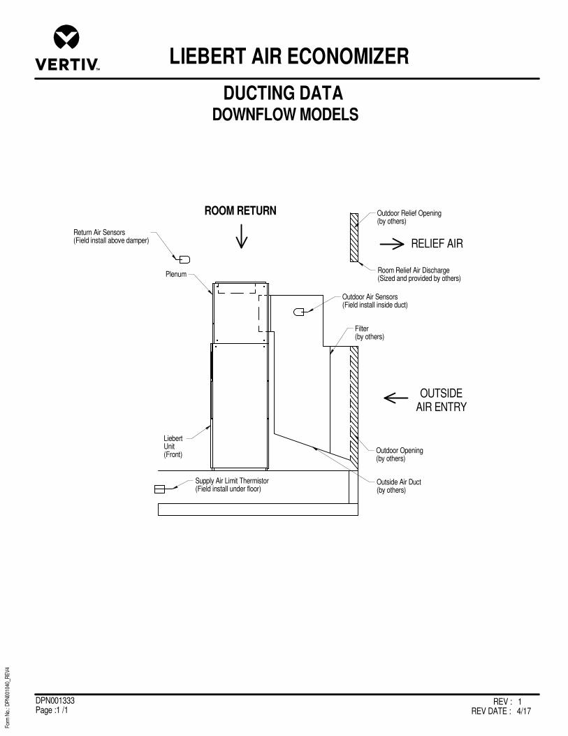
REV : 1REV DATE : 4/17
DPN001333Page :1 /1
DOWNFLOW MODELS
For
m N
o.: D
PN
0010
40_R
EV
4
DUCTING DATA
LIEBERT AIR ECONOMIZER
Liebert Unit(Front)
Plenum
ROOM RETURN
OUTSIDEAIR ENTRY
Return Air Sensors(Field install above damper)
Supply Air Limit Thermistor(Field install under floor)
Outdoor Air Sensors(Field install inside duct)
Filter (by others)
Outdoor Opening(by others)
Outdoor Relief Opening(by others)
Room Relief Air Discharge (Sized and provided by others)
RELIEF AIR
Outside Air Duct(by others)

REV : 2REV DATE : 1/17
DPN003226Page :1 /1
DOWNFLOW CW106 & CW114 MODELS
For
m N
o.: D
PN
0010
40_R
EV
4
AIR ECONOMIZER DIMENSIONAL DATA
LIEBERT CW
Plenum
Front of CW Unit
Room Return Air Damper
76"1930mm
36"914mm
34"864mm
1"25mm
1"25mm
22"559mm
REAR VIEW LEFT SIDEVIEW
TOP VIEW
FRONT VIEW (REF. ONLY)
1"25mm
Duct Collar
12"305mm
Outside Air Damper
30 1/16"764mm
112"2845mm
118"2996mm Duct Flange
2"51mm
83"2108mm
Access Panel for 2" (51mm) Pre-Filters
122"3099mm
Front of unit
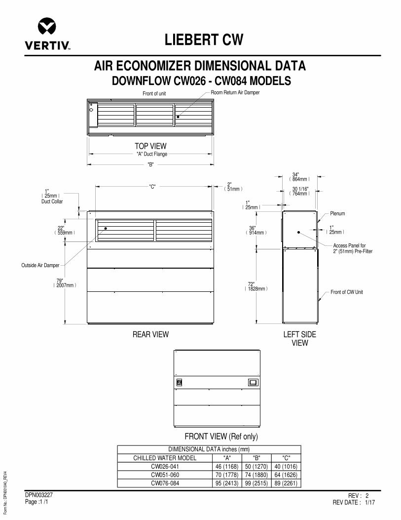
REV : 2REV DATE : 1/17
DPN003227Page :1 /1
DOWNFLOW CW026 - CW084 MODELS
For
m N
o.: D
PN
0010
40_R
EV
4
AIR ECONOMIZER DIMENSIONAL DATA
LIEBERT CW
Plenum
Front of CW Unit
Room Return Air Damper
72"1828mm
36"914mm
34"864mm
1"25mm
1"25mm
REAR VIEW LEFT SIDEVIEW
TOP VIEW
FRONT VIEW (Ref only)
1"25mm
Duct Collar
Outside Air Damper
30 1/16"764mm
"A" Duct Flange
Access Panel for2" (51mm) Pre-Filter
"B"
CHILLED WATER MODEL "A" "B" "C"
CW026-041 46 (1168) 50 (1270) 40 (1016)
CW051-060 70 (1778) 74 (1880) 64 (1626)
CW076-084 95 (2413) 99 (2515) 89 (2261)
DIMENSIONAL DATA inches (mm)
"C" 2"51mm
79"2007mm
22"559mm
Front of unit
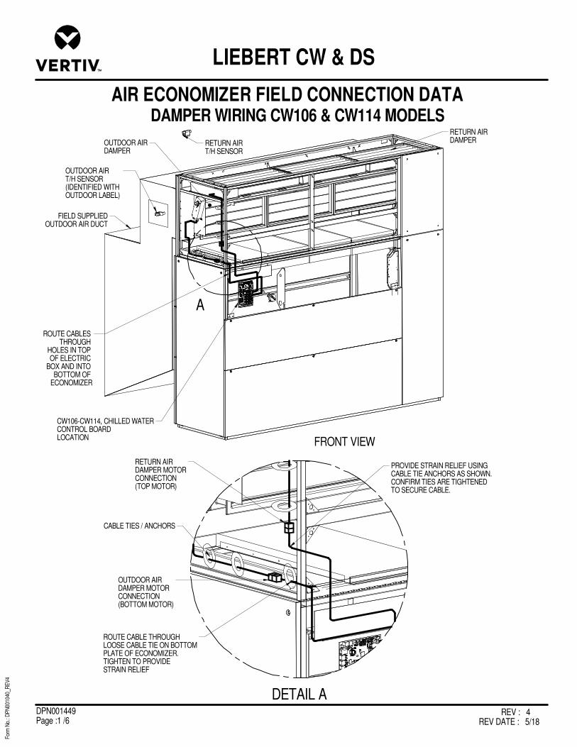
REV : 4REV DATE : 5/18
DPN001449Page :1 /6
For
m N
o.: D
PN
0010
40_R
EV
4
AIR ECONOMIZER FIELD CONNECTION DATA
LIEBERT CW & DS
A
DETAIL A
RETURN AIRDAMPER MOTORCONNECTION(TOP MOTOR)
OUTDOOR AIRDAMPER MOTORCONNECTION(BOTTOM MOTOR)
CW106-CW114, CHILLED WATERCONTROL BOARDLOCATION
PROVIDE STRAIN RELIEF USINGCABLE TIE ANCHORS AS SHOWN.CONFIRM TIES ARE TIGHTENEDTO SECURE CABLE.
CABLE TIES / ANCHORS
ROUTE CABLE THROUGHLOOSE CABLE TIE ON BOTTOMPLATE OF ECONOMIZER.TIGHTEN TO PROVIDESTRAIN RELIEF
FIELD SUPPLIEDOUTDOOR AIR DUCT
RETURN AIRT/H SENSOR
OUTDOOR AIRT/H SENSOR(IDENTIFIED WITH OUTDOOR LABEL)
ROUTE CABLES THROUGH
HOLES IN TOP OF ELECTRIC
BOX AND INTO BOTTOM OF
ECONOMIZER
RETURN AIRDAMPEROUTDOOR AIR
DAMPER
FRONT VIEW
DAMPER WIRING CW106 & CW114 MODELS

REV : 4REV DATE : 5/18
DPN001449Page :2 /6
For
m N
o.: D
PN
0010
40_R
EV
4
AIR ECONOMIZER FIELD CONNECTION DATA
LIEBERT CW & DS
RETURN AIRDAMPER MOTORCONNECTION(TOP MOTOR)
OUTDOOR AIRDAMPER MOTORCONNECTION(BOTTOM MOTOR)
PROVIDE STRAIN RELIEF USINGCABLE TIE ANCHORS AS SHOWN.CONFIRM TIES ARE TIGHTENEDTO SECURE CABLE.
CABLE TIES / ANCHORS
ROUTE CABLE THROUGHLOOSE CABLE TIE ON BOTTOMPLATE OF ECONOMIZER.TIGHTEN TO PROVIDESTRAIN RELIEF
FIELD SUPPLIEDOUTDOOR AIR DUCT
RETURN AIRT/H SENSOR
RETURN AIRDAMPER
OUTDOOR AIRDAMPER
FRONT VIEW
A
DETAIL A
2" PRE-FILTERS
ROUTE CABLESTHROUGH HOLESIN TOP OF ELECTRICBOX AND INTO THE BOTTOM OFECONOMIZER
LIEBERTCONTROL BOARDLOCATION
OUTDOOR AIRT/H SENSOR(IDENTIFIED WITH OUTDOOR LABEL)
DAMPER WIRING DS MODELS

REV : 4REV DATE : 5/18
DPN001449Page :3 /6
For
m N
o.: D
PN
0010
40_R
EV
4
AIR ECONOMIZER FIELD CONNECTION DATA
LIEBERT CW & DS
RETURN AIRDAMPER MOTORCONNECTION(TOP MOTOR)
OUTDOOR AIRDAMPER MOTORCONNECTION(BOTTOM MOTOR)
PROVIDE STRAIN RELIEF USINGCABLE TIE ANCHORS AS SHOWN.CONFIRM TIES ARE TIGHTENEDTO SECURE CABLE.
CABLE TIES / ANCHORS
ROUTE CABLE THROUGHLOOSE CABLE TIE ON BOTTOMPLATE OF ECONOMIZER.TIGHTEN TO PROVIDESTRAIN RELIEF
FIELD SUPPLIEDOUTDOOR AIR DUCT
RETURN AIRT/H SENSOR
RETURN AIRDAMPEROUTDOOR AIR
DAMPER
FRONT VIEW
A
DETAIL A
LIEBERTCONTROL BOARDLOCATION
ROUTE CABLESTHROUGH HOLESIN TOP OF ELECTRICBOX AND INTO THE BOTTOM OFECONOMIZER
2" PRE-FILTERS
OUTDOOR AIRT/H SENSOR(IDENTIFIED WITH OUTDOOR LABEL)
DAMPER WIRING CW038 - CW084 MODELS

REV : 4REV DATE : 5/18
DPN001449Page :4 /6
For
m N
o.: D
PN
0010
40_R
EV
4
AIR ECONOMIZER FIELD CONNECTION DATA
LIEBERT CW & DS
BOTH POSSIBLE LOW VOLTAGE
COMPARTMENTS SHOWN.
IDENTIFY WHICH APPLIES
B
C
D
BOTH SENSORS AND CABLESARE SHIPPED IN BOXESINSIDE ECONOMIZER
DETAIL D
CONNECT P67 ON THE CONTROL BOARDTO P66 ON THE RETURN AIR T/H SENSORUSING CABLE PROVIDED
SECURE RING TERMINAL(FOR SENSOR CABLE SHIELD)INTO BACK OF ELECTRIC BOX (EARTH GROUND)
DETAIL C
CONNECT P66 ON THE RETURN AIR T/H SENSORTO P67 ON THE CONTROLBOARD USING CABLE PROVIDED
DETAIL B
MOUNT OUTDOOR AIR SENSOR
INSIDE OF OUTDOOR AIR PLENUM
SECURE RING TERMINAL(FOR SENSOR CABLE SHIELD)
INTO METAL DUCT (EARTH GROUND)
CONNECT P66 ON THE OUTDOOR AIR T/H SENSOR
TO P67 ON THE RETURNAIR T/H SENSOR
USING CABLE PROVIDED
ROUTE CABLE THROUGHCUSTOMER CREATED HOLE
IN PLENUM, THEN SEAL
OUTDOOR AIRT/H SENSOR
RETURN AIRT/H SENSOR
FRONT VIEW
RETURN AIRT/H SENSOR
MOUNT RETURN AIRT/H SENSOR INDOORS,ABOVE UNIT RETURN
CONNECT P67 ON THE RETURN AIR T/H SENSOR
TO P66 ON THE OUTDOOR AIR T/H SENSOR
USING CABLE PROVIDED
OUTDOOR AIRT/H SENSOR(IDENTIFIED WITH OUTDOOR LABEL)
TEMPERATURE AND HUMIDITY SENSOR WIRING

REV : 4REV DATE : 5/18
DPN001449Page :5 /6
For
m N
o.: D
PN
0010
40_R
EV
4
AIR ECONOMIZER FIELD CONNECTION DATA
LIEBERT CW & DS
BOTH POSSIBLE LOW VOLTAGE
COMPARTMENTS SHOWN.
IDENTIFY WHICH APPLIES
E
CW106-CW114, CHILLED WATERRESTRICTED AIR FLOWSWITCH LOCATION
LIEBERT DS + CW038-CW084RESTRICTED AIR FLOW SWITCH LOCATION
P13FACTORY
CONNECTED
SECURE SUPPLY AIR THERMISTOR IN AIR FLOW (CW106-CW114, CHILLEDWATER LOCATION)
SECURE SUPPLY AIR THERMISTOR IN AIR FLOW (LIEBERT DS ANDCW038-CW084 UNIT LOCATION)
P13FACTORY CONNECTED
DETAIL E
RESTRICTED AIR FLOWSWITCH ALARM SETPOINT KNOB
ADJUSTMENT INSTRUCTIONS:1. UNIT MUST BE RUNNING.2. TURN ADJUSTMENT KNOB CLOCKWISE UNTIL YOU HEAR IT TRIP (UNIT WILL ALSO ALARM)3. TURN BACK COUNTERCLOCKWISE: - 1/2 TURN FOR STANDARD UNITS - 1 TURN FOR UNITS WITH VFD - OR TO DESIRED SETPOINT
RESTRICTED AIRFLOW SWITCH
UNCOIL AND EXTEND CABLETHROUGH HOLES PROVIDED IN BOTTOM OF UNIT
UNCOIL AND EXTENDCABLE THROUGHHOLES PROVIDED IN BOTTOM OF UNIT
FRONT VIEW
SUPPLY LIMIT THERMISTOR WIRING AND
RESTRICTED AIRFLOW SWITCH ADJUSTMENTRETURN AIRT/H SENSOR
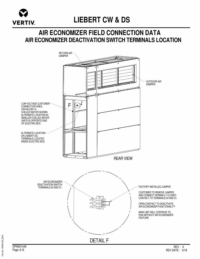
REV : 4REV DATE : 5/18
DPN001449Page :6 /6
For
m N
o.: D
PN
0010
40_R
EV
4
AIR ECONOMIZER FIELD CONNECTION DATA
LIEBERT CW & DS
24
51F
OUTDOOR AIRDAMPER
RETURN AIRDAMPER
24
51
DETAIL F
LOW VOLTAGE CUSTOMERCONNECTION AREA,CW106-CW114CHILLED WATER SHOWNALTERNATE LOCATION INSMALLER CHILLED WATERUNITS IS OPPOSITE ENDOF ELECTRIC BOX
AIR ECONOMIZERDEACTIVATION SWITCHTERMINALS 24 AND 51. FACTORY INSTALLED JUMPER
CUSTOMER TO REMOVE JUMPERAND CONNECT NORMALLY CLOSED CONTACT TO TERMINALS 24 AND 51.
OPEN CONTACT TO DEACTIVATEAIR ECONOMIZER FUNCTIONALITY
MAIN UNIT WILL CONTINUE TO RUN WITHOUT AIR ECONOMIZERFEATURE
ALTERNATE LOCATIONON LIEBERT DS,TERMINALS LOCATEDINSIDE ELECTRIC BOX
REAR VIEW
AIR ECONOMIZER DEACTIVATION SWITCH TERMINALS LOCATION

REV : 5REV DATE : 4/19
DPN003209Page : 1 /13
For
m N
o.: D
PN
0010
40_R
EV
4
LIEBERT CW
SEISMIC APPLICATION ASSUMPTIONS AND REQUIREMENTS
The International Code Council’s International Building Code (IBC) has become the primary code document for the design and installation of building systems. Vertiv has conducted analytical modeling and dynamic shake table testing of the Liebert CW product to provide an option for those systems requiring seismic certification of compliance. This certification goes beyond the equipments ability to withstand the seismic forces: the IBC system approach includes the equipment, equipment anchorage, and the connections to the equipment [power, water supply and return and ducting]. In critical applications the equipment must be capable of performing its primary function after a seismic event within the limit of certification. Certification Criteria
The Liebert CW certification is based on a maximum mapped spectral response acceleration, Ss, of 3.0g adjusted by the soil site coefficient to Soil Site Class D as the default when the site soil properties or final equipment installation location is not known. The certification maximum spectral response coefficient Sds value of 2.0g including Soil Class and Seismic Use group corrections. Soil Classes A, B, C, D, E, and Seismic Design Categories A, B, C, D, E, and F are all covered under this certification, limited by the Sds value stated above. A seismic importance factor, Ip, of 1.5 applies to this certification to include essential facility requirements and life safety applications for post event functionality.
Requirements for Anchorage
Anchors 1. Mounting requirement details such as brand, type, embedment depth, edge
spacing, anchor spacing, concrete strength, wall bracing, and special inspection must be outlined and approved by the project Structural Engineer of Record.
Anchorage Surface
2. Structural floors, and housekeeping pads must also be seismically designed and approved by the project Structural Engineer of Record to withstand the seismic anchor loads as defined on the installation drawings. The installing contractor is responsible for the proper installation of all anchors and mounting hardware,
observing the mounting requirement details outlined by the Engineer of Record. Contact the Manufacturer’s Representative if a detailed Seismic Installation Calculation Package is required.
Connections to Unit 3. Electrical wiring, conduit, and/or other connections to the equipment is the responsibility of others. Data and recommendations are supplied here and in the unit installation supplement for seismic installation.
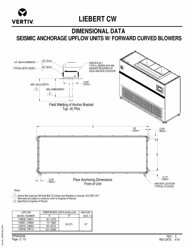
REV : 5REV DATE : 4/19
DPN003209Page : 2 /13
For
m N
o.: D
PN
0010
40_R
EV
4
LIEBERT CW
Field Welding of Anchor BracketTyp. (4) Plcs
Floor Anchoring DimensionsFront of Unit
A
B
CW038, CW041 50 (1270)
CW051, CW060 74 (1880)
CW076, CW084 99 (2515)
CW106, CW114 122 (3099)
29 (37) 1/2"
UPFLOW
MODEL NUMBER
ANCHOR
SIZE
DIMENSIONAL DATA inches (mm)
A B
ANCHOR LOCATION TYPICAL 6 PLACES
MIN. EMBEDMENT
MIN. HOLE DEPTH
(3mm)TYPICAL BOTH SIDES
1/8"
(3mm)1.8" (46mm) MINIMUM
1/8"ANSI B18.22.1TYPE A, SERIES W PLAINWASHER REQUIRED ATEACH ANCHOR LOCAITON
2 3/8"59mm
7/8"24mm
3 1/4"83mm2 3/8"
59mm
Notes:
1. Anchor Bolt sized per Hilti Kwik Bolt TZ Carbon and Stainless in concrete, ICC ESR-1917. Alternates are subject to review by Vertiv or Engineer of Record.2. Specified by Engineer of Record.
1
2
2
DIMENSIONAL DATA SEISMIC ANCHORAGE UPFLOW UNITS W/ FORWARD CURVED BLOWERS
2 5/8"67mm
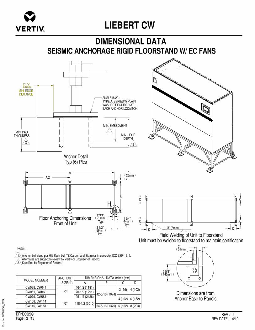
REV : 5REV DATE : 4/19
DPN003209Page : 3 /13
For
m N
o.: D
PN
0010
40_R
EV
4
LIEBERT CW
MIN. EMBEDMENT
MIN. HOLEDEPTH
MIN. PADTHICKNESS
1/8" (3mm)
ANSI B18.22.1TYPE A, SERIES W PLAINWASHER REQUIRED ATEACH ANCHOR LOCAITON
A B C D
CW038, CW041 46-1/2 (1181)
CW051, CW060 70-1/2 (1791)
CW076, CW084 95-1/2 (2426)
CW106, CW114
CW146, CW181 54-5/16 (1379) 6 (152) 8 (203)1/2"
MODEL NUMBERANCHOR
SIZE
42-5/16 (1074)
3 (76)
4 (102)
4 (102)
DIMENSIONAL DATA inches (mm)
118-1/2 (3010)
6 (152)
1/2"
Floor Anchoring DimensionsFront of Unit
Field Welding of Unit to FloorstandUnit must be welded to floorstand to maintain certification
A
A/2
1"25mm
TYP.
B
3 1/2"89mmTyp.
1 3/4"44mmTyp.
2 3/4"70mmTyp.
C
C
D D
C
C
H
Dimensions are fromAnchor Base to Panels
5 5/8"143mm
2"51mm
Anchor DetailTyp (6) Plcs
2 1/2"64mm
MIN. EDGEDISTANCE
DIMENSIONAL DATA SEISMIC ANCHORAGE RIGID FLOORSTAND W/ EC FANS
Notes:
1. Anchor Bolt sized per Hilti Kwik Bolt TZ Carbon and Stainless in concrete, ICC ESR-1917. Alternates are subject to review by Vertiv or Engineer of Record.2. Specified by Engineer of Record.
1
2
2
2

REV : 5REV DATE : 4/19
DPN003209Page : 4 /13
For
m N
o.: D
PN
0010
40_R
EV
4
LIEBERT CW
Anchor DetailTyp. (6) Places
MIN. EMBEDMENT
MIN. HOLE
DEPTHMIN. PAD
THICKNESS
1/8" (3mm)
ANSI B18.22.1TYPE A, SERIES W PLAINWASHER REQUIRED ATEACH ANCHOR LOCAITON
Floor Anchoring Dimensions
AA/2
B
1 3/4"44mm TYP.
3 1/2"89mm TYP.
Field Welding of Unit to FloorstandUnit must be welded to Floorstand
to maintain certification
C
C
D D
C
C
A B C D
CW038, CW041 46.5 (118 4.0 (102)
CW051, CW060 70.5 (1791)
CW076, CW084 95.5 (2426) 6.0 (152)
CW106, CW114
CW146, CW181 54.3 (1378) 6.0 (152) 8.0 (203)
3.0 (76)
4.0 (102)1/2"
DIMENSIONAL DATA inches (mm)MODEL NUMBER
ANCHOR
SIZE
118.5 (3010)
42.3 (1073)
1"25mm TYP.
Anchor Base to Panels
4 3/4"121mmTYP.
1 1/8"29mmTYP.
2 3/4"70mm TYP.
DIMENSIONAL DATA SEISMIC ANCHORAGE RIGID FLOORSTAND
W/ FORWARD CURVED BLOWERS
2
2
2
Notes:
1. Anchor Bolt sized per Hilti Kwik Bolt TZ Carbon and Stainless in concrete, ICC ESR-1917. Alternates are subject to review by Vertiv or Engineer of Record.2. Specified by Engineer of Record.
1
H
2 1/2"64mm
MINIMUM EDGE DISTANCE
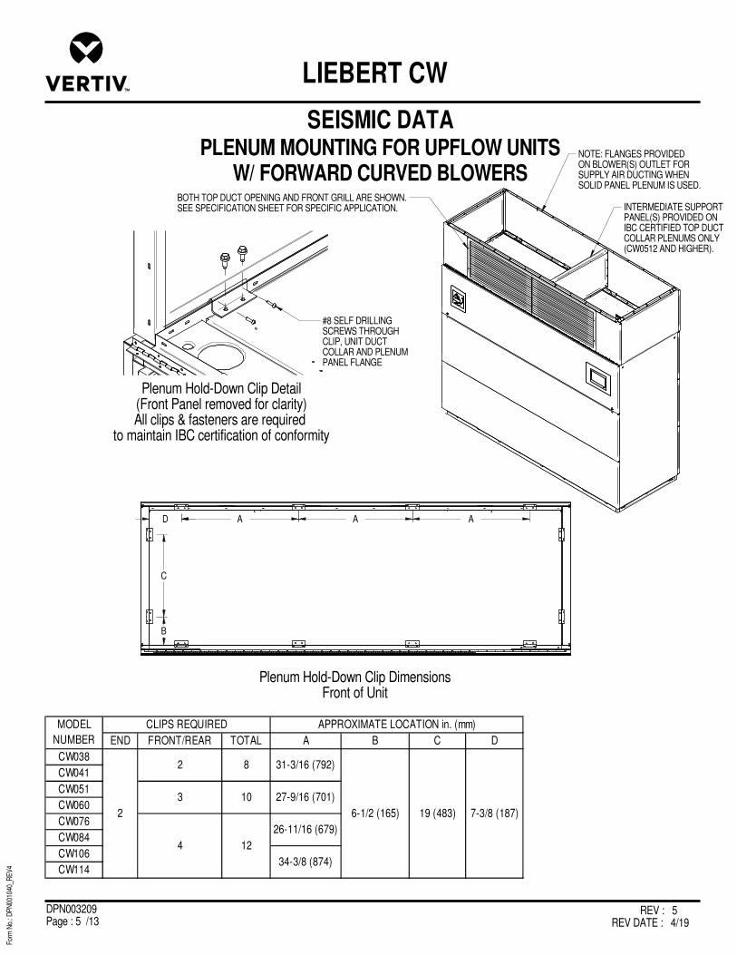
REV : 5REV DATE : 4/19
DPN003209Page : 5 /13
For
m N
o.: D
PN
0010
40_R
EV
4
LIEBERT CW
Plenum Hold-Down Clip DimensionsFront of Unit
Plenum Hold-Down Clip Detail(Front Panel removed for clarity)All clips & fasteners are required
to maintain IBC certification of conformity
END FRONT/REAR TOTAL A B C D
CW038
CW041
CW051
CW060
CW076
CW084
CW106
CW114
MODEL
NUMBER
CLIPS REQUIRED
26-11/16 (679)
27-9/16 (701)
4 12
34-3/8 (874)
APPROXIMATE LOCATION in. (mm)
82
2
31-3/16 (792)
6-1/2 (165) 19 (483) 7-3/8 (187)
3 10
BOTH TOP DUCT OPENING AND FRONT GRILL ARE SHOWN.SEE SPECIFICATION SHEET FOR SPECIFIC APPLICATION.
#8 SELF DRILLING SCREWS THROUGH CLIP, UNIT DUCT COLLAR AND PLENUM PANEL FLANGE
NOTE: FLANGES PROVIDEDON BLOWER(S) OUTLET FORSUPPLY AIR DUCTING WHENSOLID PANEL PLENUM IS USED.
INTERMEDIATE SUPPORTPANEL(S) PROVIDED ONIBC CERTIFIED TOP DUCTCOLLAR PLENUMS ONLY(CW0512 AND HIGHER).
D A A A
C
B
SEISMIC DATAPLENUM MOUNTING FOR UPFLOW UNITS
W/ FORWARD CURVED BLOWERS

REV : 5REV DATE : 4/19
DPN003209Page : 6 /13
For
m N
o.: D
PN
0010
40_R
EV
4
LIEBERT CW
INTERMEDIATE SUPPORT PANEL(S) PROVIDED ON IBC CERTIFIED TOP DUCT COLLAR PLENUMS ONLY(CW051 AND LARGER)
NOTE: FLANGES PROVIDED ON BLOWER(S) OULET FOR SUPPLY AIR DUCTING WHEN SOLID PANEL PLENUM IS USED.
Plenum Hold-Down Clip DimensionsFront of Unit
Plenum Hold-Down Clip Details(Front Panel removed for clarity)
All Clips & Fasteners are requiredto maintain IBC certification of conformity
#8 SELF DRILLING SCREWS THROUGH CLIP, UNIT DUCT COLLAR AND PLENUM PANEL FLANGE(TYPICAL ALL LOCATIONS)
1/4" SELF DRILLING SCREWS THROUGH CLIP INTO UNIT TOP(TYPICAL FRONT/REAR)
END CLIPS REAR CLIPSFRONT CLIPS
A B B B
D
C
END FRONT/REAR TOTAL A B C D
CW038
CW041
CW051
CW060
CW076
CW084
CW106
CW114
6-1/2 (165)
31-3/16 (792)
19 (483)
MODEL
NUMBER
CLIPS REQUIRED
26-11/16 (679)
27-9/16 (701)
4 12
34-3/8 (874)
2
APPROXIMATE LOCATION inches (mm)
3 10
2 8
7-3/8 (188)
SEISMIC DATAPLENUM MOUNTING FOR UPFLOW UNITS
W/ FORWARD CURVED BLOWERS

REV : 5REV DATE : 4/19
DPN003209Page : 7 /13
For
m N
o.: D
PN
0010
40_R
EV
4
LIEBERT CW
JACK
Foot Detail
4 5/8"117mm
A
B
MODEL OVERALL WIDTH A B
CW038, CW041 50 (1270) 48 (1219)
CW051, CW060 74 (1880) 72 (1829)
CW076, CW084 99 (2515) 97 (2464)
CW106, CW114 120 (3048) 118 (2997)
DIMENSIONAL DATA in. (mm)
33 (838)
H
18 3/8"467mm
NOTE:
1. The floor stand used with EC units is not symmetrical and its orientation to the Liebert CW is critical to lowering the EC fans. Unless the floor stand is installed in the correct position, the blowers will not lower into the floor stand.
2. Not applicable to 24" & 30" tall floorstands.
3. Foot provides ±1.5" (38mm) adjustment from nominal height H
2
SEISMIC DATAFLOORSTAND MOUNTING FOR DOWNFLOW CW038 - CW114 MODELS
W/ EC FANS
3

REV : 5REV DATE : 4/19
DPN003209Page : 8 /13
For
m N
o.: D
PN
0010
40_R
EV
4
LIEBERT CW
JACKFoot Detail
4 5/8"117mm
MODEL OVERALL WIDTH A B
CW146, CW181 120 (3048) 118 (2997) 45 (114)
DIMENSIONAL DATA in. (mm)
B
6 3/4"171mm
A
H
18 1/2"469mm
NOTE:
1. The floor stand used with EC units is not symmetrical and its orientation to the Liebert CW is critical to lowering the EC fans. Unless the floor stand is installed in the correct position, the blowers will not lower into the floor stand.
2. Applicable only to 48" tall floorstand.
3. Not applicable to 24" & 30" tall floorstands.
4. Foot provides ±1.5" (38mm) adjustment from nominal height H
2
3
SEISMIC DATAFLOORSTAND MOUNTING FOR DOWNFLOW CW146 - CW181 MODELS
W/ EC FANS
4

REV : 5REV DATE : 4/19
DPN003209Page : 9 /13
For
m N
o.: D
PN
0010
40_R
EV
4
LIEBERT CW
CW038, CW041 50 (1270) 48 (1219)
CW051, CW060 74 (1880) 72 (1829)
CW076, CW084 99 (2515) 97 (2464)
CW106, CW114 120 (3048) 118 (2997)
MODEL OVERALL WIDTH OF UNIT A
DIMENSIONAL DATA in. (mm)
Foot Detail
HEIGHT in. (mm)
"H" NOMINAL
12 (305)
15 (381)
18 (457)
21 (533)
24 (610)
30 (762)
36 (914)
48 (1219)
4 5/8"117mm
DIMENSIONAL DATA SEISMIC RIGID FLOORSTAND W/ FORWARD CURVED BLOWERS
Notes:
1. Foot provides u1-1/2" (38mm) adjustment from nominal height "H".
1
1
1
A
33"838mm
H
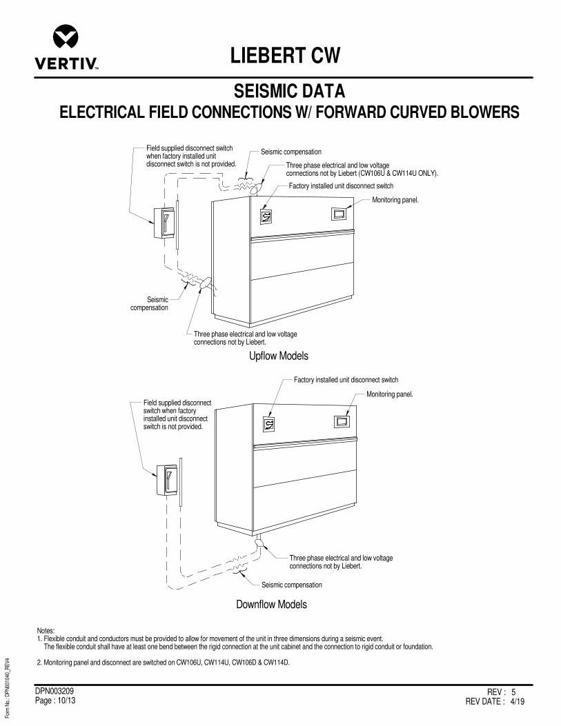
REV : 5REV DATE : 4/19
DPN003209Page : 10 /13
For
m N
o.: D
PN
0010
40_R
EV
4
LIEBERT CW
Three phase electrical and low voltage connections not by Liebert.
Factory installed unit disconnect switch
Seismic compensation
Seismiccompensation
Field supplied disconnect switchwhen factory installed unitdisconnect switch is not provided.
Monitoring panel.
Three phase electrical and low voltage connections not by Liebert (CW106U & CW114U ONLY).
Upflow Models
Three phase electrical and low voltage connections not by Liebert.
Seismic compensation
Field supplied disconnectswitch when factoryinstalled unit disconnectswitch is not provided.
Factory installed unit disconnect switch
Monitoring panel.
Downflow Models
SEISMIC DATAELECTRICAL FIELD CONNECTIONS W/ FORWARD CURVED BLOWERS
Notes:1. Flexible conduit and conductors must be provided to allow for movement of the unit in three dimensions during a seismic event. The flexible conduit shall have at least one bend between the rigid connection at the unit cabinet and the connection to rigid conduit or foundation.
2. Monitoring panel and disconnect are switched on CW106U, CW114U, CW106D & CW114D.

REV : 5REV DATE : 4/19
DPN003209Page : 11 /13
For
m N
o.: D
PN
0010
40_R
EV
4
LIEBERT CW
Anchor pipingto unit
Prefabricated seismiccompensation piping
Unit
Floor Mount
Secure pipes to floorstand
Prefabricated seismiccompensation piping
Unit
Anchor Piping
Floorstand Mount
Seismic compensation device
Upflow with floorstand: anchor to floorstandUpflow rigid mount: anchor to unitDownflow: anchor to floorstand
Anchor tofoundation
To unit
Flexible Loop Example
SEISMIC DATAPIPING FIELD CONNECTIONS
Notes:1. Flexible Loops: All units, either rigidly mounted or mounted on vibration isolators, shall be attached to the piping system using flexible loops designed for seismic movement. Flexible loops shall be capable of movement in the three axes and must completely isolate the equipment from the piping. The loops shall be suitable for an operating pressure and temperature of the system, refer to Liebert installation instructions. This includes 1/4" copper humidifier supply, condensate drainage, and chilled water supply and return. Follow manufacturer’s installation instructions for proper seismic application of flexible loops.

REV : 5REV DATE : 4/19
DPN003209Page : 12 /13
For
m N
o.: D
PN
0010
40_R
EV
4
LIEBERT CW
Downflow Model Examples
Upflow Model Examples
Seismic compensation
Seismic compensation
Seismiccompensation
Seismiccompensation
SEISMIC DATADUCT CONNECTION CONSIDERATIONS W/ FORWARD CURVED BLOWERS
Notes:1. All ducted units, either rigidly mounted or mounted on vibration isolators, shall be attached to the ducting system using flexible duct designed for seismic movement. Flexible loops shall be capable of movement in the three axes and must completely isolate the equipment from the duct work. Refer to Liebert installation instructions for ducting requirements. Follow manufacturer’s installation instructions for proper seismic application of flexible ducts.

REV : 5REV DATE : 4/19
DPN003209Page : 13 /13
For
m N
o.: D
PN
0010
40_R
EV
4
LIEBERT CW
CONNECTION DETAIL AS TESTED FOR SEISMIC CERTIFICATION
Floor Mounted Anchorage (CW114UCS)
Floorstand Supported Anchorage
Plan View of Unit Attachment
F
DETAIL F
1/8"
FASTENED TO THE SHAKE TABLEUSING 1/2" A325 BOLTS
Plan View of Attachment AnglesFRONT
Front of UnitG
DETAIL G
B2 PLACES
A
A A
A4 PLACES
B
TOTAL 'C' - 7/8" GRADE 7 THREADED RODS WITH1/8" THICK NEOPRENE PAD.
QTY SUPPORTS
A (in) B (in) C
CW114DC1 4 6
CW181DC1 6 8
MODEL NUMBERWELD LENGTH FLOORSTAND
HEIGHT (in)
6 36
1/8"
2 5/8"67mm

Vertiv | Liebert® CW System Design Catalog50
This page intentionally left blank

Appendix E: Guide Specifications
The following are the guide specifications for the Liebert® CW.
Liebert® CW System Design Catalog 51
SL-18061GS_REV8_03-20 1 Guide Specifications
Liebert® CW Guide Specifications
Chilled Water Environmental Control System
1.0 GENERAL
1.1 SUMMARY These specifications describe requirements for a Thermal Management system. The system shall be designed to control temperature and humidity conditions in rooms containing electronic equipment, with good insulation and vapor barrier. The manufacturer shall design and furnish all equipment to be fully compatible with heat-dissipation requirements of the room.
1.2 DESIGN REQUIREMENTS The Thermal Management system shall be a Liebert self-contained, factory-assembled unit. Standard 60 Hz units shall be CSA-certified to the harmonized U.S. and Canadian product safety standard, "CSA C22.2 No 236/UL 1995 for Heating and Cooling Equipment" and are marked with the CSA c-us logo.
The Liebert CW system performance shall be AHRI Certified™, the trusted mark of performance assurance for heating, ventilation, air conditioning and commercial refrigeration equipment, using AHRI Standard 1360.
1.3 SUBMITTALS Submittals shall be provided with the proposal and shall include: Single-Line Diagrams; Dimensional, Electrical, and Capacity Data; Piping and Electrical Connection Drawings.
1.4 SERVICEABILITY/ ACCESS The cabinet shall be designed so that all components are easily accessible for service and maintenance through the unit's side and front [CW038-084], front [CW106-181].
1.5 ACCEPTABLE ALTERNATIVES Acceptable alternatives shall be permitted with engineer's prior approval only. Contractor to submit a detailed summary form listing all variations to include size deviations, electrical load differences, functional and component changes and savings to end user.
1.6 QUALITY ASSURANCE The specified system shall be factory-tested before shipment. Testing shall include but shall not be limited to: Quality Control Checks, “Hi-Pot.” The system shall be designed and manufactured according to world-class quality standards. The manufacturer shall be ISO 9001 certified.
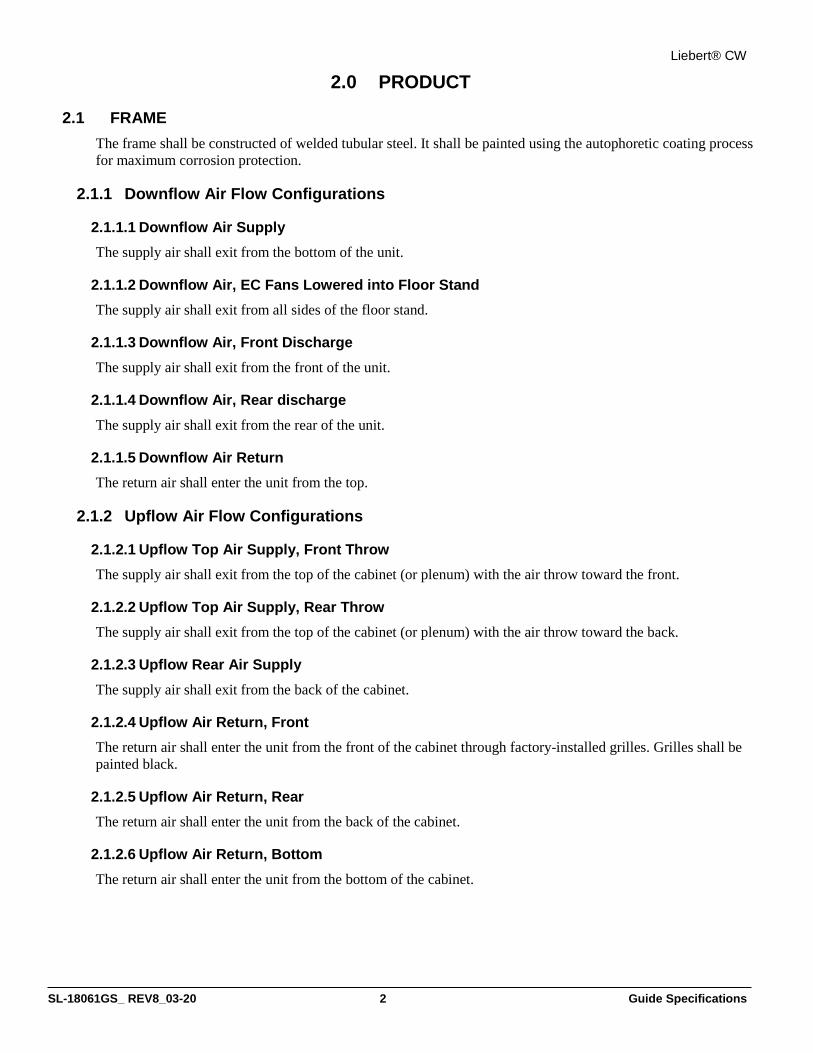
Liebert® CW
SL-18061GS_ REV8_03-20 2 Guide Specifications
2.0 PRODUCT
2.1 FRAME The frame shall be constructed of welded tubular steel. It shall be painted using the autophoretic coating process for maximum corrosion protection.
2.1.1 Downflow Air Flow Configurations
2.1.1.1 Downflow Air Supply The supply air shall exit from the bottom of the unit.
2.1.1.2 Downflow Air, EC Fans Lowered into Floor Stand The supply air shall exit from all sides of the floor stand.
2.1.1.3 Downflow Air, Front Discharge The supply air shall exit from the front of the unit.
2.1.1.4 Downflow Air, Rear discharge The supply air shall exit from the rear of the unit.
2.1.1.5 Downflow Air Return The return air shall enter the unit from the top.
2.1.2 Upflow Air Flow Configurations
2.1.2.1 Upflow Top Air Supply, Front Throw The supply air shall exit from the top of the cabinet (or plenum) with the air throw toward the front.
2.1.2.2 Upflow Top Air Supply, Rear Throw The supply air shall exit from the top of the cabinet (or plenum) with the air throw toward the back.
2.1.2.3 Upflow Rear Air Supply The supply air shall exit from the back of the cabinet.
2.1.2.4 Upflow Air Return, Front The return air shall enter the unit from the front of the cabinet through factory-installed grilles. Grilles shall be painted black.
2.1.2.5 Upflow Air Return, Rear The return air shall enter the unit from the back of the cabinet.
2.1.2.6 Upflow Air Return, Bottom The return air shall enter the unit from the bottom of the cabinet.

Liebert® CW
SL-18061GS_ REV8_03-20 3 Guide Specifications
2.1.3 Exterior Panels The exterior panels shall be insulated with a minimum 1 in. (25 mm), 1.5 lb. (0.68 kg) density fiber insulation. The main front panel shall have captive quarter-turn fasteners. The main unit color shall be ______. The accent color shall be _________.
2.2 FILTERS The filter chambers for CW038-084 filters are located within the cabinet and serviceable from either end of the unit.
The filter chambers for CW106 and CW114 are located within the cabinet and serviceable from the front of the unit.
The filter chambers for CW146 and CW181 are field mounted on the top of the cooling unit. The filters are located in an 18-in. (457-mm) plenum, which is serviceable from the front of the unit.
For CW038-084 units with rear-return filter boxes, the filter chambers shall be field-mounted on the rear of the cooling unit and are serviceable from either end of the unit.
2.2.1 Filters, 4-in. MERV8 and MERV11 Filters shall be deep-pleated 4-in. filters with an ASHRAE 52.2-2007 MERV8 or ASHRAE 52.2-2007 MERV11.
2.2.2 Filters, 2-in. Pre-filter with 4-in. Filter MERV8 and MERV11 Filters shall be 2-in. ASHRAE 52.2-2007 MERV8 pre-filter, with 4-in. ASHRAE 52.2-2007 MERV8 or MERV11 efficiency filter.
2.2.3 Extra Filter Set ____ extra set(s) of filters shall be provided per system.
2.3 LOCKING DISCONNECT SWITCH The manual disconnect switch shall be mounted in the high-voltage section of the electrical panel. The switch shall be accessible from the outside of the unit with the door closed and prevent access to the high-voltage electrical components until switched to the “OFF” position.
2.4 SHORT-CIRCUIT CURRENT RATING (SCCR) The electrical panel shall provide at least 65,000A SCCR (60hz).
Short-circuit current rating (SCCR) is the maximum short-circuit current a component or assembly can safely withstand when protected by a specific overcurrent protective device(s) or for a specified time.

Liebert® CW
SL-18061GS_ REV8_03-20 4 Guide Specifications
2.5 FAN SECTION
2.5.1 Electronically Commutated (EC) Fans The fans shall be plug/plenum type, single-inlet and shall be dynamically balanced. The drive package shall be direct drive, electronically commutated and variable speed. The fans shall be located to draw air over the A-frame coil to ensure even air distribution and maximum coil performance. EC fans shall be available on downflow models, and fans may be lowered into a raised floor with a minimum height of 24 in. (610 mm). EC fans may operate within the Liebert CW cabinet, instead of under the floor.
EC fans shall be available on upflow models and fans shall operate outside the unit in a factory-provided plenum.
• Upflow CW038–114: The fan motor(s) shall be 4.0 hp (3.0 kW) with maximum speed of 1520 rpm; quantity 1 for CW038–41; 2 for CW051–084; 3 for CW106–114.
• Downflow CW038–CW041: The fan motor shall be 4.0 hp (3.0 kW) with a maximum operating speed of 1520 rpm; quantity 1.
• Downflow CW051 and CW060: The fan motors shall be 3.4 hp (2.5 kW) with a maximum operating speed of 1700 rpm; quantity 2. (Power rating for 380–480V. For 200–240V, power is 3.6 hp [2.7 kW]).
• Downflow CW076–CW084: The fan motors shall be 4.0 hp (3.0 kW) with a maximum operating speed of 1520 rpm; quantity 2.
• Downflow CW106–CW114: The fan motors shall be 4.0 hp (3.0 kW) with a maximum operating speed of 1520 rpm; quantity 3.
• CW146: The fan motors shall be 3.7 hp (2.8 kW) with a maximum operating speed of 1230 rpm; quantity 3.
• CW181: The fan motors shall be 4.9 hp (3.7 kW) with a maximum operating speed of 1370 rpm; quantity 3.
2.5.2 Forward Curved Blower—Optional The blower section shall be designed for ___ CFM (____CMH) at an external static pressure of ___ in. wg. (Pa). The fan shall be the centrifugal type, double-width, double-inlet, and shall be factory-balanced as a completed assembly. The shaft shall be heavy-duty steel with self-aligning ball bearings with a minimum lifespan of 100,000 hours.
The fans shall be located to draw air over the A-frame coil to ensure even air distribution and maximum coil performance. The fan motor shall be ____ hp at 1750 rpm at 60 Hz and mounted on an adjustable slide base. The drive package shall be two-belt, variable speed, sized for 200% of the fan motor horsepower.
2.6 CHILLED WATER CONTROL VALVE The water circuit shall include a 2-way (3-way) modulating valve. The valve shall be designed for up to 400 PSI (2758 kPa) water pressure. The Liebert iCOM shall position the valve in response to room conditions.

Liebert® CW
SL-18061GS_ REV8_03-20 5 Guide Specifications
2.7 CHILLED WATER COIL The evaporator coil shall be A-frame design for downflow and upflow units and have ____ ft2 (m2) face area, ____ rows deep.
It shall be constructed of copper tubes and aluminum fins and have a maximum face velocity of ____ ft per minute (m/s) at ____ CFM (m3).
The water circuit shall be designed to distribute water into the entire coil face area. The coil shall be supplied with ____ °F (°C) entering water temperature, with a ____ °F (°C) temperature rise. The coil shall require ____ GPM (l/s) of chilled water and the pressure drop shall not exceed ____ PSI (kPa). The entire coil assembly shall be mounted in a stainless steel-condensate drain pan.
2.8 HUMIDIFIER
2.8.1 Infrared Humidifier—OPTIONAL A humidifier shall be factory-installed inside the unit. The humidifier shall be of the infrared type, consisting of high-intensity quartz lamps mounted above and out of the water supply. The humidifier pan shall be stainless steel and arranged to be serviceable without disconnecting water-supply lines, drain lines or electrical connections. The complete humidifier section shall be pre-piped ready for final connection. The infrared humidification system shall use by-pass air to prevent over-humidification of the controlled space. The auto-flush system shall automatically flush deposits from the humidifier pan. The system shall be field adjustable to change the cycle time to suit local water conditions.
A minimum 1-in. (25-mm) air gap within the humidifier piping assembly, in compliance with ASME A112.1.2 section 2.4.2 (backsiphonage testing), shall prevent back-flow of the humidifier supply water.
2.9 REHEAT
2.9.1 Electric Reheat—OPTIONAL The Thermal Management unit shall include a factory-installed reheat to control temperature during dehumidification. The low-watt density, 304/304, stainless-steel, finned-tubular electric reheat coils. The reheat section shall include UL/CSA recognized safety switches to protect the system from overheating.
2.9.2 Hot Water Reheat—OPTIONAL The hot water reheat coil shall have copper tubes and aluminum fins. The control system shall be factory pre-piped with a 2-way motorized control valve. A cleanable Y-strainer is factory-installed on hot-water supply line. Upflow model requires a 22 ¾-in. (58-cm) high plenum with grille.

Liebert® CW
SL-18061GS_ REV8_03-20 6 Guide Specifications
3.0 CONTROLS
3.1 LIEBERT ICOM™ MICROPROCESSOR CONTROL WITH 7-IN. COLOR TOUCHSCREEN
The Liebert iCOM shall be microprocessor-based with a 7-inch, high definition, capacitive, color touchscreen display and shall be mounted in an ergonomic, aesthetically pleasing housing. The display and housing shall be viewable while the front panel is open or closed. The controls shall be menu driven. The system shall display user menus for active alarms, event log, graphic data, unit view/status overview (including the monitoring of room conditions, operational status in percentage of each function, date and time), total run hours, various sensors, display setup and service contacts. A password shall be required to make system changes. Service menus shall include setpoints, standby settings (lead/lag), timers/sleep mode, alarm setup, sensor calibration, maintenance/wellness settings, options setup, system/network setup, auxiliary boards and diagnostics/service mode. The Liebert iCOM control shall provide Ethernet/RS-485 ports dedicated for BMS connectivity (i.e. Base-Comms).
• Password Protection - The Liebert iCOM shall contain two unique passwords to protect against unauthorized changes. An auto hide/show feature shall allow the user to see applicable information based on the login used.
• Unit Backup and Restore - The user shall be able to create safe copies of important control parameters. The Liebert iCOM shall have the capacity for the user to automatically backup unit configuration settings to internal memory or USB storage drive. Configuration settings may be transferred to another unit for a more streamlined unit startup.
• Parameter Download—The Liebert iCOM shall enable the user to download a report that lists parameter names, factory default settings and user-programmed settings in .csv format for remote reference.
• Parameter Search- The Liebert iCOM shall have search fields for efficient navigation and parameter lookup.
• Parameter Directory - The Liebert iCOM shall provide a directory that lists all parameters in the control. The list shall provide Line ID numbers, parameter labels, and current parameter values.
• Context Sensitive Help - The Liebert iCOM™ will have an on-board help database. The database shall provide context sensitive help to assist with setup and navigation of the menus.
• Display Setup - The user shall be able to configure the display information based on the specific user’s preference. Language, units of measure, screen contrast, home screen layout, back-light timer and the hide/show of certain readouts will be configurable through the display.
• Additional Readouts - The Liebert iCOM shall enable the user to configure custom widgets on the main screen. Widget options shall include items such as fan speed, call for cooling, call for free cooling, maintenance status, call for hot water reheat, call for electric reheat, call for dehumidification, call for humidification, airflow, static pressure, fluid flow rate and cooling capacity.
• Status LED’s - The Liebert iCOM shall provide the user with the unit’s operating status using an integral LED. The LED shall indicate if the unit has an active alarm; if the unit has an active alarm that has been acknowledged; or if the unit is On, Off or in standby status.
• Event Log - The Liebert iCOM shall automatically store the last 400 unit-only events (messages, warnings and alarms).
• Service Contact Information - The Liebert iCOM shall have the capacity to store the local service or sales contact information.
• Upgradeable - Liebert iCOM firmware upgrades shall be performed through a USB connection.
• Timers/Sleep Mode - Menu shall allow various customer settings for turning on/Off unit.

Liebert® CW
SL-18061GS_ REV8_03-20 7 Guide Specifications
• Menu Layout - The menus will be broken out into two main menu screens: User screen and Service screen. The User screen contains the menus to access parameters required for basic unit control and setup. The Service screen is designed for service personnel and provides access to advanced control setup features and diagnostic information.
• Sensor Calibration – The menus shall allow unit sensors to be calibrated with external sensors.
• Maintenance/Wellness Settings - The menus shall allow reporting of potential component problems before they occur.
• Options Setup - The menus shall provide operation settings for the installed components.
• Auxiliary Boards - The menus shall allow setup of optional expansion boards.
• Various Sensors - The menus shall allow setup and display of optional custom sensors. The control shall include four customer-accessible analog inputs for sensors provided by others. The analog inputs shall accept a 4 to 20mA signal. The user shall be able to change the input to 0 to 5VDC or 0 to 10VDC. The gains for each analog input shall be programmable from the front display. The analog inputs shall be able to be monitored from the front display.
• Diagnostics/Service Mode - The Liebert iCOM control shall be provided with self-diagnostics to aid in troubleshooting. The microcontroller board shall be diagnosed and reported as pass/not pass. Control inputs shall be indicated as On or Off at the front display. Control outputs shall be able to be turned On or Off from the front display without using jumpers or a service terminal. Each control output shall be indicated by an LED on a circuit board.
• Base-Comms for BMS Connectivity – The Liebert iCOM controller shall provide one Ethernet Port and RS-485 Port dedicated for BMS Connectivity. Provides ground fault isolated RS-485 Modbus, BACnet IP & Modbus IP network connectivity to Building Management Systems for unit monitoring and management. Also, provides ground fault isolated 10/100 baseT Ethernet connectivity for unit monitoring and management. The supported management interfaces include SNMP for Network Management Systems, HTTP for web page viewing, SMTP for email, and SMS for mobile messaging. The iCOM controller can support dual IP on a single network and one 485 protocol simultaneously.
3.2 ALARMS All unit alarms shall be annunciated through both audio and visual cues, clearly displayed on the screen, automatically recorded in the event log and communicated to the customer’s Building Management System/Building Automation System. The Liebert iCOM control shall activate an audible and visual alarm in event of any of the following conditions:
• High Temperature
• Low Temperature
• High Humidity
• Low Humidity
• EC Fan Fault
• Change Filters
• Loss of Air Flow
• Loss of Power
• Custom Alarms

Liebert® CW
SL-18061GS_ REV8_03-20 8 Guide Specifications
Custom alarm inputs shall be provided to indicate facility-specific events. Custom alarms can be identified with programmable labels. Frequently used alarm inputs include:
• Leak Under Floor
• Smoke Detected
• Standby Unit On
Each alarm (unit and custom) can be separately enabled or disabled, selected to activate the common alarm and programmed for a delay of 0 to 255 seconds.
3.3 LIEBERT ICOM™ CONTROL METHODS AND OPTIONS The Liebert iCOM shall be factory-set to allow precise monitoring and control of the condition of the air entering and leaving the unit. This control shall include predictive methods to control air flow and cooling capacity-based control sensors installed. Proportional and Tunable PID shall also be user-selectable options.
3.3.1 Controlling Sensor Options The Liebert iCOM shall be flexible in the sense that it shall allow controlling the capacity and fan from multiple different sensor selections. The sensor selections shall be:
3.3.1.1 Cooling Capacity • Supply
• Remote
• Return
3.3.1.2 Fan Speed • Supply
• Remote
• Return
• Manual (for diagnostic or to receive a signal from the BMS through the Liebert remote monitoring devices or analog input)
• Static Pressure
3.3.2 Temperature Compensation The Liebert iCOM shall have the ability to adjust the capacity output based on supply and return temperature conditions to meet SLA guidelines while operating to highest efficiency.
3.3.3 Humidity Control Dew point and relative humidity control methods shall be available (based on user preference) for humidity control within the space.

Liebert® CW
SL-18061GS_ REV8_03-20 9 Guide Specifications
3.4 MULTI-UNIT COORDINATION Liebert iCOM™ teamwork shall save energy by preventing multiple units in an area from operating in opposing modes. Teamwork shall allow the control to optimize a group of connected cooling units equipped with Liebert iCOM using the U2U (Unit to Unit) network. There shall be three modes of teamwork operation:
• Teamwork Mode 1 (Parallel): Is best in small rooms with balanced heat loads. The controlling temperature and humidity sensor readings of all units in operation (fan on) are collected to be used for an average or worst-case sensor reading (user selectable). The master unit shall send the operating requirements to all operating units in the group. The control band (temperature, fan and humidity) is divided and shared among the units in the group. Each unit will receive instructions on how to operate from the Master unit based on how far the system deviates from the setpoints. Evaporator fans and cooling capacity are ramped in parallel.
• Teamwork Mode 2 (Independent): Is best applied in large rooms with unbalanced heat loads. The Liebert iCOM calculates the worse-case demand for heating, cooling humidification and dehumidification. Based on the greatest demand within the group, each unit operates independently, meaning that the unit may respond to the thermal load and humidity conditions based on the unit's controlling sensors. All sensor readings are shared.
• Teamwork Mode 3 (Optimized Aisle): May be employed in large and small rooms with varying heat loads. Optimized Aisle is the most efficient teamwork mode that allows the unit to match cooling capacity with heat load. In the Optimized Aisle mode, the fans operate in parallel. Fans can be controlled exclusively by remote temperature or using static pressure with a secondary remote temperature sensor(s) as an override to ensure the inlet rack temperature is being met. Cooling (Chilled Water Valve or Economizer) is controlled through unit supply air conditions. The Liebert iCOM calculates the average or worst-case sensor reading (user-selectable) for heating, cooling humidification and dehumidification. Based on the demand within the group, units will be allowed to operate within that mode until room conditions are satisfied. This is the best form of control for a room with an unbalanced load.
3.5 STANDBY LEAD-LAG The Liebert iCOM shall allow planned rotation to keep equal run time on units and provide automated emergency rotation of operating and standby units.
3.6 STANDBY UNIT CASCADING The Liebert iCOM cascade option shall allow the units to turn On and Off based on heat load when utilizing Teamwork Mode 1, Independent mode or Teamwork Mode 3, Optimized Aisle mode with remote temperature sensors. In Teamwork Mode 1, Cascade mode will stage units on based on the temperature and humidity readings and their deviation from setpoint. In Teamwork 3 Mode, Cascade mode dynamically coordinates the fan speed to save energy and to meet the cooling demands. For instance, with a Liebert iCOM group of six units and only 50% of the heat load, the Liebert iCOM shall operate only four units at 80% fan speed and leave the other two units in standby. As the heat load increases, the Liebert iCOM shall automatically respond to the new load and bring on another unit, increasing the units in operation to five. As the heat load shifts up or down, the control shall meet the need by cascading units On or putting them into standby.
3.7 VIRTUAL MASTER As part of the robust architecture of the Liebert iCOM control, it shall allow for a virtual master that coordinates operation. The Virtual Master function provides smooth control operation if the group’s communication is compromised. When the lead unit, which is in charge of component staging in teamwork, unit staging and standby rotation, becomes disconnected from the network, the Liebert iCOM automatically assigns a virtual master. The virtual master assumes the same responsibilities as the master until communication is restored.

Liebert® CW
SL-18061GS_ REV8_03-20 10 Guide Specifications
3.8 VIRTUAL BACK-DRAFT DAMPER Liebert iCOM™ shall allow the use of a virtual back-draft damper, eliminating the need for a mechanical damper. This shall allow the fans to spin slowly (15% or less) to act as a damper.
3.9 SYSTEM AUTO RESTART The auto restart feature shall automatically restart the system after a power failure. Time delay shall be programmable. An optional capacitive buffer may be provided for continuous control operation through a power failure.
3.10 WIRED SUPPLY SENSOR Each Liebert iCOM shall have one factory-supplied and connected supply air sensor that may be used as a controlling sensor or reference. When multiple sensors are applied for control purposes, the user shall be able to control based on a maximum or average temperature reading.
3.11 SEQUENTIAL LOAD ACTIVATION On initial startup or restart after power failure, each operational load shall be sequenced with a minimum of one-second delay to minimize total inrush current.
3.12 CW QUICK START Each Liebert iCOM controller shall have the option to enable Chilled Water Quick-Start. After a loss of power, iCOM application normally requires approximately 60 seconds to reboot prior to the unit providing airflow and cooling output. With CW Quick-Start enabled, the end-user may configure a specific airflow output percentage and cooling capacity output percentage as desired. The unit shall operate at these configured values within approximately 10 seconds after a power restoration all while the iCOM application is rebooting. After iCOM has fully booted, the unit will continue normal operation.
3.13 ADAPTIVE PID CW AUTO-TUNING iCOM shall support the use of Liebert’s auto-tuning feature called Adaptive PID. Adaptive PID may be used for fan speed control or cooling capacity control. With Adaptive PID selected, iCOM shall automatically recognize oscillations across multiple sub-systems relating to the PI tuning associated with either mode of control or correct those oscillations with zero human intervention. This feature allows for better overall system operation and responds well to increasing/decreasing system loads.
3.14 SUPPLY SENSOR AGGREGATION Each Liebert iCOM controller shall support the Supply Sensor Aggregation feature. Supply Sensor Aggregation allows for the use of additional remote 2T temperature sensors that are used to calculate an aggregated supply air temperature value which may be used for cooling capacity control. Each iCOM controller can support up to five additional remote 2T sensors for supply sensor aggregation.

Liebert® CW
SL-18061GS_ REV8_03-20 11 Guide Specifications
4.0 MISCELLANEOUS OPTIONS
4.1 FLOW SWITCH—OPTIONAL The flow switch shall activate the alarm system should the chilled water supply be interrupted. The switch shall be designed for up to 400 PSI (2758 kPa) water pressure and shipped loose for field installation.
4.2 VARIABLE SPEED DRIVE—OPTIONAL A variable speed drive (VSD) is available for models CW106 and CW114 to reduce energy consumption. The fan motor speed shall be varied from 100% to 60% of rated speed in response to room conditions. This shall be controlled automatically by the Liebert iCOM™ control. The variable-speed-drive option shall be available with an infrared humidifier.
4.3 WIRED REMOTE SENSOR(S)—OPTIONAL Each Liebert iCOM shall have up to 10 2T sensors (20 sensor readings total) for control or reference. As part of the U2U network, these sensors shall be shared and used to control the cooling units and provide greater flexibility, visibility and control, using that to respond to changes in the conditioned space. When the sensors are used for control, the user may set the control to be based on a maximum or average of a selected highest temperature reading.
4.4 DUAL CHILLED WATER VALVE STAGING—OPTIONAL The control shall provide special staging options on dual chilled water valve applications. The chilled-water valves may be staged in parallel, cascade or alternate lead operation.
Parallel control shall allow both chilled-water valves to operate at the same time, following the same open/close command as the room conditions deviate from the setpoint.
Cascade control shall allow the valves to operate in stages. Only 1 circuit shall be operated to maintain the conditioned space temperature. If the room condition is not held with 1 circuit in operation, the control will automatically stage a second valve on to maintain room conditions. An automatic timer may be used to alternate the lead valve to keep equal component run time.
Alternate operation shall allow 1 circuit to work as lead and the second circuit to act as backup. The lead valve will rotate based on valve run time, or the user can alternate the lead valve using a customer input connection.
4.5 HIGH TEMPERATURE SENSOR—OPTIONAL The high temperature sensor shall immediately shut down the environmental control system when activated. The high temperature sensor shall be mounted in the electrical panel with the sensing element in the return air.
4.6 CONDENSATE PUMP, DUAL FLOAT—OPTIONAL The pump shall have a capacity of _______ GPM (_______ l/m) at _______ ft head (_______ kPa). The pump shall be complete with integral dual-float switch, pump, motor assembly and reservoir. The secondary float shall send a signal to the local alarm and shut-down the unit upon a high-water condition. The pump shall be shipped loose for field installation on Chilled Water units that are upflow with bottom return. They are also shipped loose for under-floor field installation on CW038-CW060 units with EC fans.
4.7 LIEBERT LIQUI-TECT™ SENSORS (MAXIMUM OF 2 PER UNIT)—OPTIONAL Provide ____ (quantity) solid-state water sensors under the raised floor.

Liebert® CW
SL-18061GS_ REV8_03-20 12 Guide Specifications
4.8 SMOKE SENSOR—OPTIONAL The smoke sensor shall immediately shut-down the Thermal Management system and activate the alarm system when activated. The smoke sensor shall be mounted in the electrical panel with the sensing element in the return-air compartment. The smoke sensor is not intended to function as or replace any room smoke-detection system that may be required by local or national codes. The smoke sensor shall include a supervision contact closure.
4.9 LIEBERT SITESCAN™ SITE MONITORING SYSTEM—OPTIONAL Provide a Liebert SiteScan monitoring system with the Liebert CW. The Liebert SiteScan shall have the capability of monitoring and changing (at the user’s direction) the temperature setpoints and sensitivities of each unit. The printer shall provide the user with chronological alarm information. It shall also be capable of being programmed to print out environmental conditions or operating modes at each unit.
4.10 LOW-VOLTAGE TERMINAL PACKAGE INCLUDES—OPTIONAL • Remote Shutdown Terminals - 2 additional pairs of terminals provide the customer with additional
locations to remotely shut-down the unit by field-installed devices or controls.
• Extra Common-Alarm Contacts - 2 additional pairs of terminals provide the customer with normally open contacts for remote indication of unit alarms.
• Main-Fan Auxiliary Switch - 1 set of normally open contacts wired to the EC-fan motor contactor will close when EC-fan operation is required. This set of dry contacts could also be used to initiate air economizer operation. Air economizer and associated devices by others.
• Liqui-tect Shutdown - 1 pair of dry contacts for the Liqui-tect sensor signal will provide unit shut down. (Liqui-tect sensor is not included.)
4.11 REHEAT & HUMIDIFIER LOCKOUT—OPTIONAL The reheat and humidifier lockout includes the necessary relays to disable the reheat and humidifier from an external customer supplied 24-V signal while on emergency power.
4.12 REMOTE HUMIDIFIER CONTACT—OPTIONAL A pair of N/O contacts provided for connection to a remote humidifier that allows the unit's humidity controller to control a humidifier outside the unit. Power to operate the remote humidifier does not come from the unit.
4.13 LIEBERT vNSA™ NETWORK SWITCH—OPTIONAL The Liebert vNSA network switch is designed for networking multiple iCOM unit-level controllers together. There shall be two different styles of the vNSA14 panel available:
• vNSA14 – enclosure with network switches only
• vNSA14-iCOM-H – enclosure with network switches and 9” iCOM color touchscreen display
Each offering shall be housed inside a steel enclosure secured with a key lock and contain two network switches, providing a total of 14 Ethernet ports available for iCOM controller unit-to-unit networking. The Liebert vNSA requires field supplied, hard wiring, 16AWG, 100-240VAC universal (12V, 1.5A) single-phase input power supply for 120V or 230V operation with factory supplied power connector.
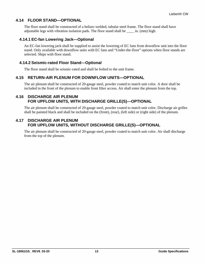
Liebert® CW
SL-18061GS_ REV8_03-20 13 Guide Specifications
4.14 FLOOR STAND—OPTIONAL The floor stand shall be constructed of a heliarc-welded, tubular steel frame. The floor stand shall have adjustable legs with vibration isolation pads. The floor stand shall be ____ in. (mm) high.
4.14.1 EC-fan Lowering Jack—Optional An EC-fan lowering jack shall be supplied to assist the lowering of EC fans from downflow unit into the floor stand. Only available with downflow units with EC fans and “Under-the-floor” options when floor stands are selected. Ships with floor stand.
4.14.2 Seismic-rated Floor Stand—Optional The floor stand shall be seismic-rated and shall be bolted to the unit frame.
4.15 RETURN-AIR PLENUM FOR DOWNFLOW UNITS—OPTIONAL The air plenum shall be constructed of 20-gauge steel, powder coated to match unit color. A door shall be included in the front of the plenum to enable front filter access. Air shall enter the plenum from the top.
4.16 DISCHARGE AIR PLENUM FOR UPFLOW UNITS, WITH DISCHARGE GRILLE(S)—OPTIONAL
The air plenum shall be constructed of 20-gauge steel, powder coated to match unit color. Discharge air grilles shall be painted black and shall be included on the (front), (rear), (left side) or (right side) of the plenum.
4.17 DISCHARGE AIR PLENUM FOR UPFLOW UNITS, WITHOUT DISCHARGE GRILLE(S)—OPTIONAL
The air plenum shall be constructed of 20-gauge steel, powder coated to match unit color. Air shall discharge from the top of the plenum.

Liebert® CW
SL-18061GS_ REV8_03-20 14 Guide Specifications
5.0 EXECUTION
5.1 INSTALLATION OF THERMAL MANAGEMENT UNITS
5.1.1 General The user shall install Thermal Management units in accordance with manufacturer’s installation instructions. The units shall be installed plumb and level, firmly anchored in locations indicated and shall maintain manufacturer’s recommended clearances.
5.1.2 Electrical Wiring The user shall install and connect electrical devices furnished by the manufacturer but not specified to be factory mounted. The manufacturer shall furnish a copy of manufacturer’s electrical connection diagram submittal to electrical contractor.
5.2 PIPING CONNECTIONS The user shall install and connect devices furnished by the manufacturer but not specified to be factory-mounted. The manufacturer shall furnish a copy of piping connection diagram submittal(s) to the piping contractor.
5.2.1 Supply and Drain Water Piping The user shall startup Thermal Management units in accordance with the manufacturer's startup instructions. The manufacturer shall test controls and demonstrate compliance with requirements.
5.3 FIELD QUALITY CONTROL Start cooling units in accordance with manufacturer's startup instructions. Test controls and demonstrate compliance with requirements. These specifications describe requirements for a computer-room environmental-control system. The system shall be designed to maintain temperature and humidity conditions in the rooms containing electronic equipment.
The manufacturer shall design and furnish all equipment to be fully compatible with heat-dissipation requirements.
5.4 WARRANTY START-UP AND CONTROL PROGRAMMING Install the indoor unit in accordance with manufacturer's installation instructions provided with seismic option. Firmly anchor maintaining manufacturer's recommended clearances. Mounting requirement details such as anchor brand, type, embedment depth, edge spacing, anchor-to-anchor spacing, concrete strength, special inspection and attachment to non-building structures must be outlined and approved by the Engineer of Record for the projection or building. Electrical, pipe and duct connections must permit movement in three dimensions and isolate the unit from field connections. Electrical conduit shall be flexible, having at least one bend between the rigid connection at the unit cabinet and the connection to rigid conduit or foundation. The piping flexible connection or loop must be suitable for the operation pressure and temperature of the system. Furnish copy of manufacturer's piping connection diagram submittal to piping contractor.

Vertiv | Liebert® CW System Design Catalog52
This page intentionally left blank

Vertiv | Liebert® CW System Design Catalog

Vertiv.com | Vertiv Headquarters, 1050 Dearborn Drive, Columbus, OH, 43085, USA
© 2020 Vertiv Group Corp. All rights reserved. Vertiv and the Vertiv logo are trademarks or registered trademarks of Vertiv Group Corp. All other names and logos referred to are tradenames, trademarks or registered trademarks of their respective owners. While every precaution has been taken to ensure accuracy and completeness herein, Vertiv Group Corp.assumes no responsibility, and disclaims all liability, for damages resulting from use of this information or for any errors or omissions. Specifications are subject to change withoutnotice.
SL-18061_REV9_04-20