LIE DETECTOR (OR POLYGRAPHY) - RcciitLIE DETECTOR (OR POLYGRAPHY) By SRIJEETA MUKHERJEE (Roll No....
23
LIE DETECTOR (OR POLYGRAPHY) By SRIJEETA MUKHERJEE (Roll No. 11705514031) SUKANYABASU (Roll No. 11705514034) TANIYA SEN (Roll No. 11705514038) MENTOR-Prof. KALYAN BISWAS Project submitted in partial fulfillment for the Degree of B. Tech in Applied Electronics & Instrumentation Engineering under West Bengal University of Technology DEPARTMENT OF APPLIED ELECTRONICS & INSTRUMENTATION ENGINEERING,RCC INSTITUTE OF INFORMATION TECHNOLOGY, CANAL SOUTH ROAD, BELIAGHATA, KOLKATA – 700015, MAY 2018
Transcript of LIE DETECTOR (OR POLYGRAPHY) - RcciitLIE DETECTOR (OR POLYGRAPHY) By SRIJEETA MUKHERJEE (Roll No....
LIE DETECTOR (OR POLYGRAPHY)
By
SRIJEETA MUKHERJEE (Roll No. 11705514031)
SUKANYABASU (Roll No. 11705514034)
TANIYA SEN (Roll No. 11705514038)
MENTOR-Prof. KALYAN BISWAS
Project submitted in partial fulfillment for the
Degree of B. Tech in Applied Electronics &
Instrumentation Engineering under West Bengal
University of Technology
DEPARTMENT OF APPLIED ELECTRONICS &
INSTRUMENTATION ENGINEERING,RCC INSTITUTE OF
INFORMATION TECHNOLOGY, CANAL SOUTH ROAD,
BELIAGHATA, KOLKATA – 700015,
MAY 2018

LIE DETECTOR
Page 2
ACKNOWLEDGEMENT
It is a great privilege for us to express our profound gratitude to our respected teacher Mr.
Kalyan Biswas, Applied Electronics &Instrumentation Engineering, RCC Institute of
Information Technology, for his constant guidance, valuable suggestions, supervision and
inspiration throughout the course work without which it would have been difficult to complete
the work within scheduled time.
We would like to express our gratitude towards Other Faculty for his/her kind co-operation and
encouragement which helped me in completion of this project.
We are also indebted to the Head of the Department, Applied Electronics &Instrumentation
Engineering, RCC Institute of Information Technology for permitting us to pursue the project.
We would like to take this opportunity to thank all the respected teachers of this department for
being a perennial source of inspiration and showing the right path at the time of necessity.
SRIJEETA MUKHERJEE
SUKANYA BASU
TANIYA SEN
LIE DETECTOR
Page 3
CERTIFICATE OF APPROVAL
The project report titled “Lie Detector (Polygraph)” prepared by SRIJEETA MUKHERJEE
Roll No: 11705514031; SUKUNYA BASU Roll No: 11705514034; TANIYA SEN Roll
No:11705514038; is hereby approved and certified as a creditable study in technological subjects
performed in a way sufficient for its acceptance for partial fulfilment of the degree for which it is
submitted.
It is to be understood that by this approval, the undersigned do not, necessarily endorse or
approve any statement made, opinion expressed or conclusion drawn therein, but approve the
project only for the purpose for which it is submitted.
--------------------------------- -------------------------------
Mr.KALYAN BISWAS Mr.KALYAN BISWAS
Assistant Professor Assistant Professor
[Supervisor] [Head of the Department]
APPLIED ELECTRONICS & APPLIED ELECTRONICS &
INSTRUMENTATION ENGINEERING INSTUMENTATION ENGINEERING
RCCIIT, KOLKATA RCCIIT, KOLKATA
...........................................
[Examiner]
LIE DETECTOR
Page 4
RECOMMENDATION
I hereby recommend that the project report titled “Lie Detector (Polygraph)” prepared by
SRIJEETA MUKHERJEE Roll No: 11705514031; SUKANYA BASU Roll No:
11705514034; TANIYA SEN Roll No:11705514038; accepted in partial fulfillment of the
requirement for the Degree of Bachelor of Technology in Applied Electronics &Instrumentation
Engineering, RCC Institute of Information Technology.
--------------------------------- -------------------------------
Mr.KALYAN BISWAS Mr.KALYAN BISWAS
Assistant Professor Assistant Professor
[Supervisor] [Head of the Department]
APPLIED ELECTRONICS & APPLIED ELECTRONICS &
INSTRUMENTATION ENGINEERING INSTUMENTATION ENGINEERING
RCCIIT, KOLKATA RCCIIT, KOLKATA
LIE DETECTOR
Page 5
TABLE OF CONTENTS
Chapter name Page no
• Review on polygraph 6
• Operational terms 7
• Early Method of detecting 8
• Polygraph 9
• Question Formulation 10
• Components description 11
• Components and their specifications 12
• Data sheet of components 13 - 18
• Components cost estimation table 19
• Hardware picture 20
• Circuit Diagram 21
• Output diagram 22
• Work plan 23
• Conclusion 24
• References 25
• Datasheet (ATTACHED) .
LIE DETECTOR
Page 6
REVIEW ON POLYGRAPH
The researches in Forensic Psychology have had great interest in deception detection methods.
Lie-detection using polygraph has been the most extensively used tools for extracting
information from a suspect who is believed to be suppressing revealing the truth. By entering the
portfolio of physiological responses, a subject makes to each successive question, the
polygrapher established a baseline reaction from which the significant deviations are observed
and interpreted as indicators of deception. To determine whether subjects are lying or hiding
something related to the event took place, the first approach to deception detection relied on
anxiety-induced autonomic indicators, using polygraphs measuring pulse, blood pressure,
respiration, and galvanic skin response. The modern era of lie detection began around the turn of
the 20th century.
• In 1885, an Italian named Cesar Lombroso
• In the 1930s the father of the polygraph, Leonard Keeler
• Raskin and Honts, 2002
• Davidson and Irwin, 1999; Cacioppo et al., 2000; Kosslynetal 2002
• Davis, 1961
• Ben-Shakhar (1977)
• Technology Assessment, 1983
• In 1973, Abrams reviewed reports of Polygraphs from 1917
• Lykken in 1981 challenged the control question technique (CQT)
• Bradley & Warfield, 1984
• Stern,2002
• Keckler, 2005
• Honts, C. R., Raskin, D. C., &Kircher, J. C. (1987).
• Bradley MacLaren, & Carle, 1996
• Siddle, 1991
• Ben-Shakhar&Furedy, 1990
LIE DETECTOR
Page 7
OPERATIONAL TERMS
POLYGRAPH – is an instrument for the recording of changes in blood pressure; pulse rate,
respiratio and skin resistance as indication of emotional disturbances especially of lying when
questioned.
The word was derived from the word POLYmeans “many” and GRAPHS means “writing
chart”.
POLYGRAPHY – it is the scientific method of detecting deception, using a polygraph
machine. n
FEAR – is emotional response to specific danger that appears to beyond a persons defensive
power.
STIMULUS – is a force or motion reaching the organism and excites the receptors.
REACTION – it is an action in mental attitude evokes by external influence.
DECEPTION – is an act of deceiving or misleading usually accompanied by lying.
DETECTION – It is an act of discovery of existence, presence of fact or something hidden or
obscure.
LYING – the uttering or conveying of falsehood or creating a false or misleading information
with the intention of affecting wrongfully the acts and opinion of other.
LIE DETECTOR
Page 8
EARLY METHODS OF DETECTING
• Trial by Combat
• Trial by Ordeal
• Trial by Iron Hot Ordeal
• Ordeal by Balance
• Ordeal of Rice Chewing
• Donkey’s Tall Ordeal
LIE DETECTOR
Page 9
WHAT IS POLYGRAPH
The polygraph is used to test or question individuals for the purpose of detecting deception or
verifying truth of statements through a visual, permanent and simultaneous recording of a
person’s cardiovascular and respiratory pattern as a minimum instrumentation requirement.
A polygraph (commonly referred to as a LIE DETECTOR) is an instrument that measures and
records several physiological responses such as:
• BLOOD PRESSURE
• PULSE
• RESPIRATION
• SKIN CONDUCTIVITY
Here ,the subject is asked and answers a series of questions, on the basis that false answers will
produce distinctive measurements. The polygraph measures physiological changes caused by the
SYMPATHETIC NERVOUS SYSTEM during questioning.
The polygraph instrument usually measures four to six physiological reactions recorded by three
different medical instruments that are combined in one machine.
Older polygraph machines were equipped with long strips of paper that moved slowly beneath
pens that recorded the various physiological responses.
Newer equipment uses transducers to convert the information to digital signals that can be stored
on computers and analyzed using sophisticated mathematical algorithms.
LIE DETECTOR
Page 10
QUESTION FORMULATION
Questions formulated are short, simple and direct answerable by either “Yes” or “No” only,
phrased in the language easily understood by the subjects.
The questions must be clear and must have reference to only one element of an offense of fact.
The underlying theory of the polygraph is that when people lie they also get measurably nervous
about lying.
The heartbeat increases, blood pressure goes up, breathing rhythms change, perspiration
increases, etc.
A baseline for these physiological characteristics is established by asking the subject questions
whose answers the investigator knows.
Deviation from the baseline for truthfulness is taken as sign of lying .
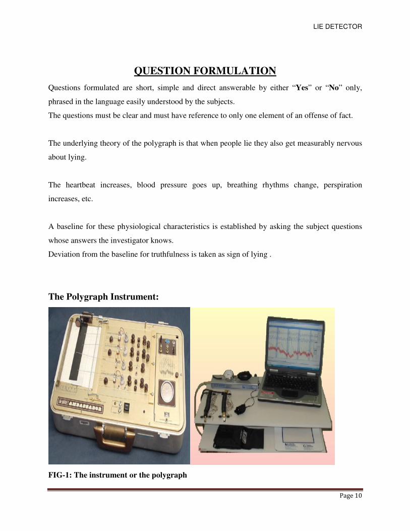
The Polygraph Instrument:
FIG-1: The instrument or the polygraph
LIE DETECTOR
Page 11
COMPONENTS DESCRIPTION
ARDUINO UNO
The Arduino UNO is a widely used open-source microcontroller board based on
the ATmega328P microcontroller and developed by Arduino.The board is equipped with sets of
digital and analog input/output (I/O) pins that may be interfaced to various expansion boards
(shields) and other circuits.The board features 14 Digital pins and 6 Analog pins. It is
programmable with the Arduino IDE(Integrated Development Environment) via a type B USB
cable.It can be powered by a USB cable or by an external 9 volt battery, though it accepts
voltages between 7 and 20 volts.
LM35 SENSOR
The LM35 is an integrated circuit sensor that can be used to measure temperature with an
electrical output proportional to the temperature (in °C).It can measure temperature more
accurately than a using a thermistor. The sensor circuitry is sealed and not subject to oxidation .
The LM35 generates a higher output voltage than thermocouples and may not require that the
output voltage be amplified . The LM35 has an output voltage that is proportional to the Celsius
temperature . The scale factor is .01V/°C.
KY039 SENSOR
While sticking a finger between the infrared diode and the photo transistor you can detect the
pulse at the signal out.
The explanation of the functionality of a photo transistor is simple: It works like a normal
transistor - you will detect a higher electricity if the control voltage is higher. Instead of the
control voltage, the photo transistor uses the light. If it it's a stronger light, you will measure a
higher electricity.
LIE DETECTOR
Page 12
DATASHEEET OF COMPONENTS
DATASHEET OF ARDUINO UNO:
• Microcontroller ATmega328
• Operating Voltage 5V
• Input Voltage (recommended) 7-12V
• Input Voltage (limits) 6-20V
• Digital I/O Pins 14 (of which 6 provide PWM output)
• Analog Input Pins 6
• DC Current per I/O Pin 40 Ma
• DC Current for 3.3V Pin 50 mA
• Flash Memory 32 KB (ATmega328) of which 0.5 KB used by boot loader
• SRAM 2 KB (ATmega328)
• EEPROM 1 KB (ATmega328)
• Clock Speed 16 MHz
KY-039 HEARTBEAT SENSOR:
This project uses bright infrared (IR) LED and a phototransistor to detect the pulse of the
finger, a red LED flashes with each pulse. Pulse monitor works as follows: The LED is
the light side of the finger, and phototransistor on the other side of the finger,
phototransistor used to obtain the flux emitted, when the blood pressure pulse by the
finger when the resistance of the photo transistor will be slightly changed. The project's
schematic circuit as shown, We chose a very high resistance resistor R1, because most of
the light through the finger is absorbed, it is desirable that the phototransistor is sensitive
enough. Resistance can be selected by experiment to get the best results. The most
important is to keep the shield stray light into the phototransistor. For home lighting that
is particularly important because the lights at home mostly based 50HZ or 60HZ
fluctuate, so faint heartbeat will add considerable noise.
When running the program the measured values are printed. To get a real heartbeat from
this could be challenging.
LIE DETECTOR
Page 13
LM-035 TEMPERATURE SENSOR
The LM35 series are precision integrated-circuit temperature devices with an output
voltage linearly proportional to the Centigrade temperature. The LM35 device has an
advantage over linear temperature sensors calibrated in Kelvin, as the user is not required
to subtract a large constant voltage from the output to obtain convenient Centigrade
scaling. The LM35 device does not require any external calibration or trimming to
provide typical accuracies of ±¼°C at room temperature and ±¾°C over a full −55°C to
150°C temperature range. Lower cost is assured by trimming and calibration at the wafer
level. The low-output impedance, linear output, and precise inherent calibration of the
LM35 device makes interfacing to readout or control circuitry especially easy. The
device is used with single power supplies, or with plus and minus supplies. As the LM35
device draws only 60 µA from the supply, it has very low self-heating of less than 0.1°C
in still air. The LM35 device is rated to operate over a −55°C to 150°C temperature
range, while the LM35C device is rated for a −40°C to 110°C range (−10° with improved
accuracy). The LM35-series devices are available packaged in hermetic TO transistor
packages, while the LM35C, LM35CA, and LM35D devices are available in the plastic
TO-92 transistor package. The LM35D device is available in an 8-lead surface-mount
small-outline package and a plastic TO-220 package.
Features
• Calibrated Directly in Celsius (Centigrade)
• Linear + 10-mV/°C Scale Factor
• 0.5°C Ensured Accuracy (at 25°C)
• Rated for Full −55°C to 150°C Range
• Suitable for Remote Applications
• Low-Cost Due to Wafer-Level Trimming , Operates From 4 V to 30 V
• Less Than 60-µA Current Drain
• Low Self-Heating, 0.08°C in Still Air
• Non-Linearity Only ±¼°C Typical , Low-Impedance Output, 0.1 Ω for 1-mA Load
2 Applications
• Power Supplies
LIE DETECTOR
Page 14
• Battery Management
• HVAC
• Appliances
9 VOLT BATTERY
The nine-volt battery, or 9-volt battery, is a common size of battery that was introduced
for the early transistor radios. It has a rectangular prism shape with rounded edges and a
polarized snap connector at the top. This type is commonly used in walkie-
talkies, clocks and smoke detectors.
The nine-volt battery format is commonly available in primary carbon-zinc and alkaline
chemistry, in primary lithium iron disulfide, and in rechargeable form in nickel-cadmium,
nickel-metal hydride and lithium-ion. Mercury-oxide batteries of this format, once common,
have not been manufactured in many years due to their mercury content. Designations for
this format include NEDA 1604 and IEC 6F22 (for zinc-carbon) or MN1604 6LR61 (for
alkaline). The size, regardless of chemistry, is commonly designated PP3—a designation
originally reserved solely for carbon-zinc, or in some countries, E or E-block.
Most nine-volt alkaline batteries are constructed of six individual 1.5 V LR61 cells enclosed
in a wrapper. These cells are slightly smaller than LR8D425 AAAA cells and can be used in
their place for some devices, even though they are 3.5 mm shorter. Carbon-zinc types are
made with six flat cells in a stack, enclosed in a moisture-resistant wrapper to prevent drying.
Primary lithium types are made with three cells in series.
In 2007, 9-volt batteries accounted for 4% of alkaline primary battery sales in the US. In
Switzerland in 2008, 9-volt batteries totalled 2% of primary battery sales and 2% of
secondary battery sales.
CONNECTORS
The battery has both terminals in a snap connector on one end. The smaller circular (male)
terminal is positive, and the larger hexagonal or octagonal (female) terminal is the negative
contact. The connectors on the battery are the same as on the connector itself; the smaller one
connects to the larger one and vice versa.[2]
The same snap-style connector is used on other
battery types in the Power Pack (PP) series. Battery polarization is normally obvious since
mechanical connection is usually only possible in one configuration. A problem with this style of
connector is that it is very easy to connect two batteries together in a short circuit which quickly
discharges batteries, generating heat and possibly a fire. Because of this hazard, nine-volt
batteries should be kept in the original packaging until they are going to be used.
LIE DETECTOR
Page 15
SPECIFICATIONS
The most common type of nine-volt battery is commonly referred to simply as 9-volt, although
there are less common nine-volt batteries of different sizes. Codes for the usual size include PP3
(for size and voltage, any technology), 6LR61 (IEC code for alkaline batteries), and in Japan
006P.
The PP3 size battery is 48.5 mm × 26.5 mm × 17.5 mm or 1.91 in × 1.04 in × 0.69 in. Both
terminals are at one end and their centers are 1⁄2inch (12.7 mm) apart.
Inside an alkaline or carbon-zinc 9-volt battery there are six cylindrical or flat cells connected in
series. Some brands use welded tabs internally to attach to the cells, others press foil strips
against the ends of the cells.
BC547A TRANSISTOR
Features :
• Bi-Polar NPN Transistor
• DC Current Gain (hFE) is 800 maximum
• Continuous Collector current (IC) is 100mA
• Emitter Base Voltage (VBE) is 6V
• Base Current(IB) is 5mA maximum
• Available in To-92 Package
Description on BC547
BC547 is a NPN transistor hence the collector and emitter will be left open (Reverse biased)
when the base pin is held at ground and will be closed (Forward biased) when a signal is
provided to base pin. BC547 has a gain value of 110 to 800, this value determines the
amplification capacity of the transistor. The maximum amount of current that could flow through
the Collector pin is 100mA, hence we cannot connect loads that consume more than 100mA
using this transistor. To bias a transistor we have to supply current to base pin, this current (IB)
should be limited to 5mA.
When this transistor is fully biased then it can allow a maximum of 100mA to flow across the
collector and emitter. This stage is called Saturation Region and the typical voltage allowed
across the Collector-Emitter (VCE) or Base-Emitter (VBE) could be 200 and 900 mV respectively.
When base current is removed the transistor becomes fully off, this stage is called as the Cut-off
Region and the Base Emitter voltage could be around 660 mV.
BC547 as Switch
When a transistor is used as a switch it is operated in the Saturation and Cut-Off Region as
LIE DETECTOR
Page 16
explained above. As discussed a transistor will act as an Open switch during Forward Bias and as
a Closed switch during Reverse Bias, this biasing can be achieved by supplying the required
amount of current to the base pin. As mentioned the biasing current should maximum of 5mA.
Anything more than 5mA will kill the Transistor; hence a resistor is always added in series with
base pin. The value of this resistor (RB) can be calculated using below formulae.
RB = VBE / IB …..(1)
Where, the value of VBE should be 5V for BC547 and the Base current (IB depends on the
Collector current (IC). The value of IB should not exceed ma.
BC547 as Amplifier
A Transistors acts as an Amplifier when operating in Active Region. It can amplify power,
voltage and current at different configurations.
Some of the configurations used in amplifier circuits are
1. Common emitter amplifier
2. Common collector amplifier
3. Common base amplifier
Of the above types common emitter type is the popular and mostly used configuration.
When uses as an Amplifier the DC current gain of the Transistor can be calculated by
using the below formulae
DC Current Gain = Collector Current (IC) / Base Current (IB) …..(2)
NOTE : DATASHEET ARE ATTACHED AT THE LAST OF THE THESIS FOR SOME COMPONENTS
LIE DETECTOR
Page 17
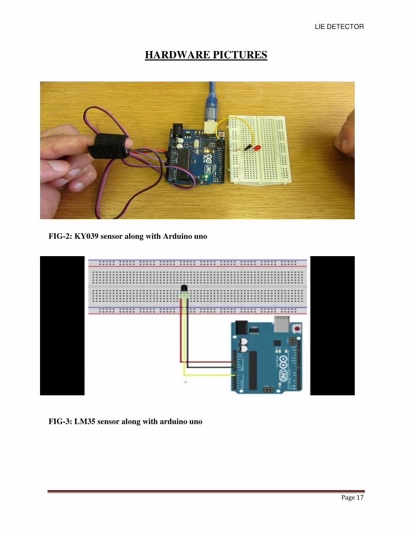
HARDWARE PICTURES
FIG-2: KY039 sensor along with Arduino uno
FIG-3: LM35 sensor along with arduino uno
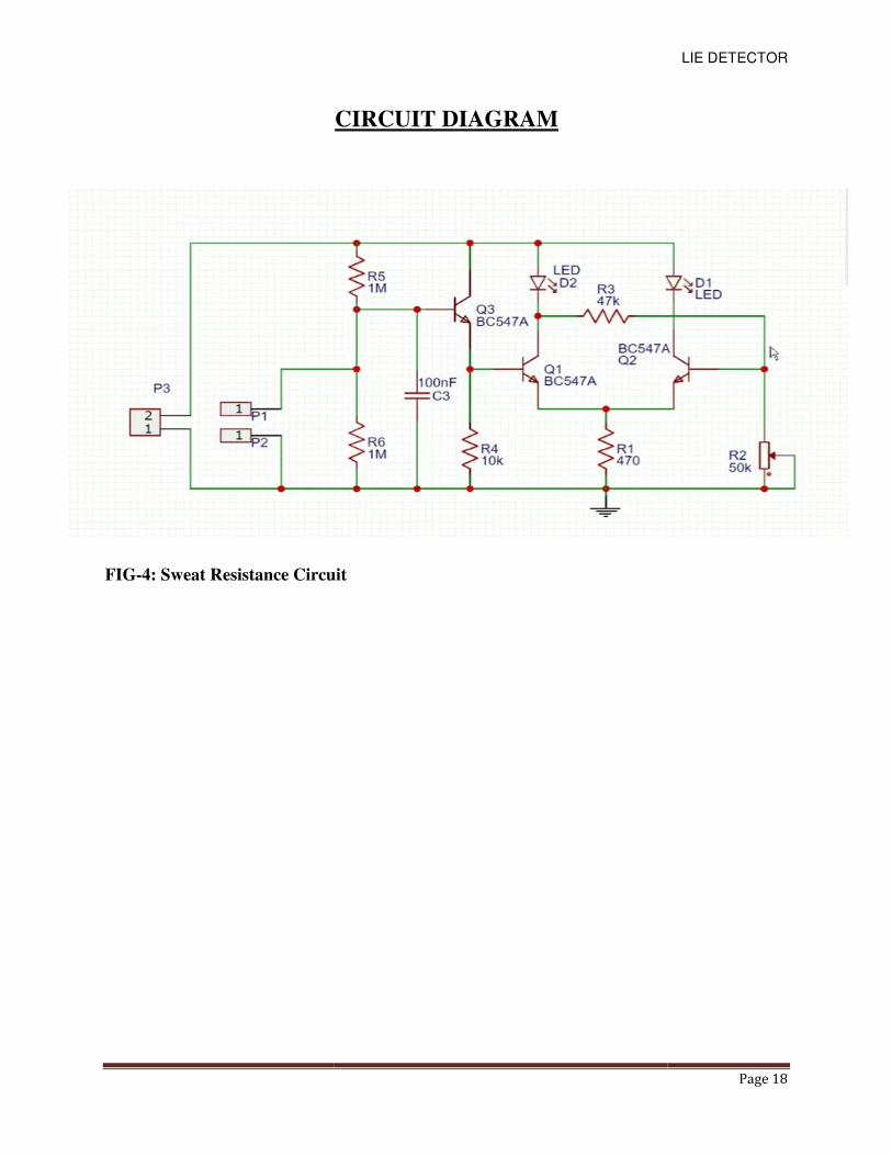
FIG-4: Sweat Resistance Circuit
CIRCUIT DIAGRAM
: Sweat Resistance Circuit
LIE DETECTOR
Page 18
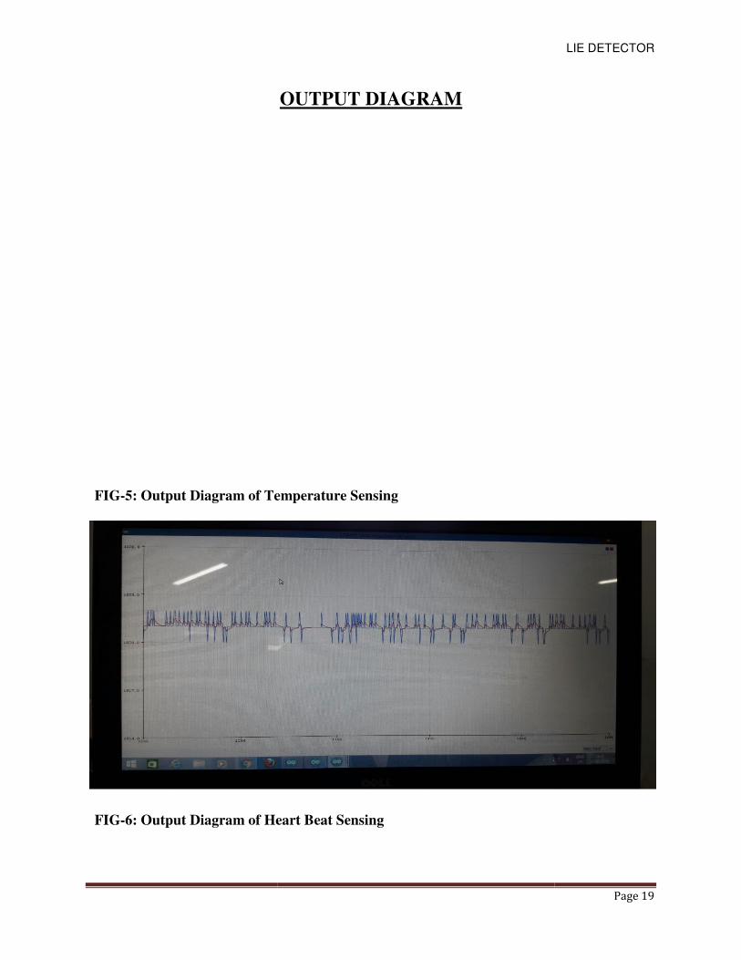
FIG-5: Output Diagram of Temperature Sensing
FIG-6: Output Diagram of Heart Beat Sensing
OUTPUT DIAGRAM
: Output Diagram of Temperature Sensing
: Output Diagram of Heart Beat Sensing
LIE DETECTOR
Page 19
LIE DETECTOR
Page 20
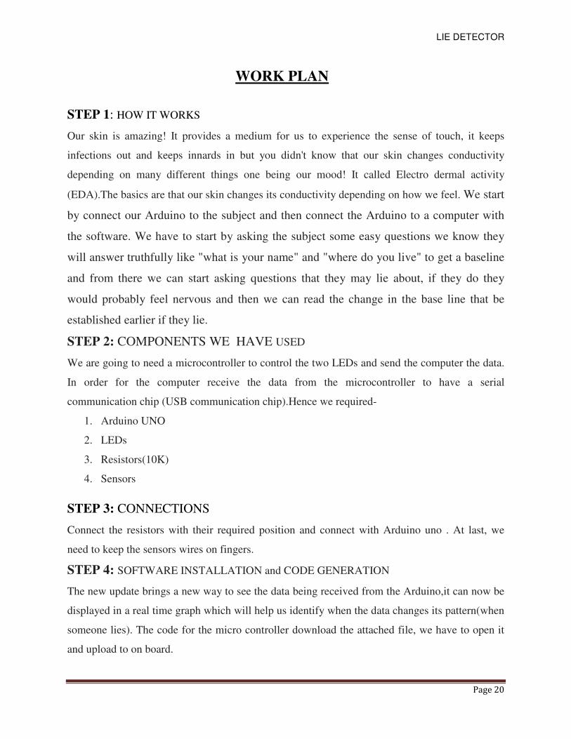
WORK PLAN
STEP 1: HOW IT WORKS
Our skin is amazing! It provides a medium for us to experience the sense of touch, it keeps
infections out and keeps innards in but you didn't know that our skin changes conductivity
depending on many different things one being our mood! It called Electro dermal activity
(EDA).The basics are that our skin changes its conductivity depending on how we feel. We start
by connect our Arduino to the subject and then connect the Arduino to a computer with
the software. We have to start by asking the subject some easy questions we know they
will answer truthfully like "what is your name" and "where do you live" to get a baseline
and from there we can start asking questions that they may lie about, if they do they
would probably feel nervous and then we can read the change in the base line that be
established earlier if they lie.
STEP 2: COMPONENTS WE HAVE USED
We are going to need a microcontroller to control the two LEDs and send the computer the data.
In order for the computer receive the data from the microcontroller to have a serial
communication chip (USB communication chip).Hence we required-
1. Arduino UNO
2. LEDs
3. Resistors(10K)
4. Sensors
STEP 3: CONNECTIONS
Connect the resistors with their required position and connect with Arduino uno . At last, we
need to keep the sensors wires on fingers.
STEP 4: SOFTWARE INSTALLATION and CODE GENERATION
The new update brings a new way to see the data being received from the Arduino,it can now be
displayed in a real time graph which will help us identify when the data changes its pattern(when
someone lies). The code for the micro controller download the attached file, we have to open it
and upload to on board.
LIE DETECTOR
Page 21
CONCLUSION
Thus in our project “LIE DETECTOR” we have been able to establish three parameters that is
the sweat resistance detection, temperature measurement and heart rate measurement .Therefore
with this three parameter we can detect whether a person is telling the lie or not.
But as this is a low cost project for this reason there are many kind of noises for which we are
getting garbage values and hence the actual reading is not showing sometimes.
We also had think of two other parameters to include in our project i.e. ECG and EEG but due to
lack of time and budget problem we could not able to come up with these two parameters.
Otherwise we are able to accomplish our aim with the former three parameters which we have
mentioned earlier in our work plan.
LIE DETECTOR
Page 22
LIE DETECTOR
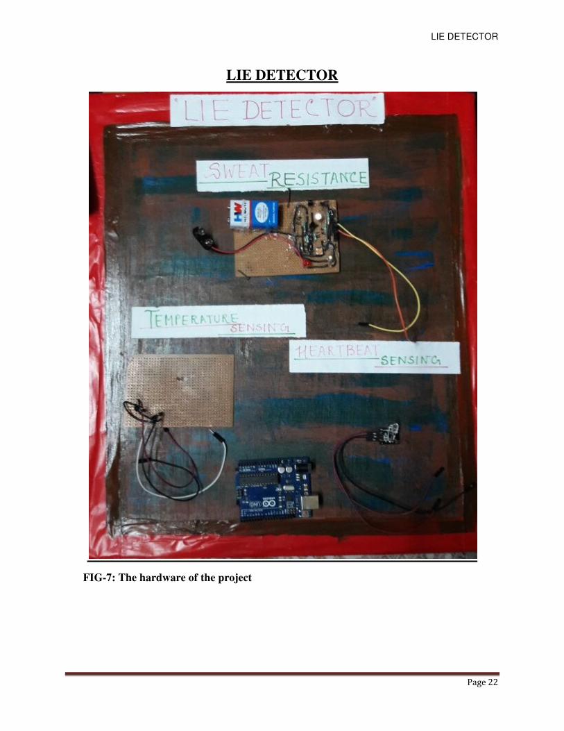
FIG-7: The hardware of the project
LIE DETECTOR
Page 23
REFERENCES
1. https://en.wikipedia.org/wiki/Polygraph
2. https://www.google.co.in/search?q=polygraphy&source
3. https://science.howstuffworks.com › Science › Physical Science › Forensic
4. Sciencehttps://www.google.com/search+lie.detect/0907
5. heart+beat+sensing+by+ky039&oq=heart+beat+sensing+by+ky039&gs_l=psy
6. temperature+sensing+by+lm35&oq=temperature+sensing+by+lm35&gs_l=psy
7. http://www.alldatasheet.com/view.jsp?searchword=lm35&gclid=cjokcqwoptxbrcgar
isaknyf2vmcvwofadhb_g6baxghsve1jy48xynrdv316iwyjofqclukweaauj4ealw_wcb
8. http://www.alldatasheet.com/view.jsp?searchword=capacitor&gclid=cjokcqwoptxbr
cgarisaknyf2vmcvwofadhb_g6baxghsve1jy48xynrdv316iwyjofqclukweaauj4ealw_w
cb
9. http://www.alldatasheet.com/view.jsp?searchword=arduino_uno&gclid=cjokcqwopt
xbrcgarisaknyf2vmcvwofadhb_g6baxghsve1jy48xynrdv316iwyjofqclukweaauj4ealw
_wcb
10. heartbeatsensingbyky039&oq=heartbeatsensingbyky039&gs_word
11. https://www.google.co.in/search?q=polygraphytheworldforum
12. http://www.alldatasheet.com/view.jsp?searchword=bc547a&gclid=cjokcqwoptxbrcg
arisaknyf2vmcvwofadhb_g6baxghsve1jy48xynrdv316iwyjofqclukweaauj4ealw_wcb