Mechanical Testing of Composite Steel and Reactive Powder ...

LICENCEfor
Licensee:
Date:
See publications covering the same Subject Area
Subscribe to our Free Newsletters about Australian Standards® in Legislation; ISO, IEC, BSI and more
Learn how to Manage Standards Collections Online
Learn about LexConnect, All Jurisdictions, Standards referenced in Australian legislation
Know when a Standard has changed
Become an SAI Global Standards Sales Affi liate
Click on the red box above to activate the Licence Agreement scroll bar.
Representing hundreds of Standards bodies including:

AS 1710—2007
Australian Standard®
Non-destructive testing—Ultrasonic testing of carbon and low alloy steel plate and universal sections—Test methods and quality classification
AS
17
10
—2
00
7
Lice
nsed
to M
r M
ark
Fin
nane
on
1 O
ctob
er 2
014.
1 u
ser
pers
onal
lice
nse
only
. Cop
ying
, cop
y/pa
stin
g, s
tora
ge &
dis
trib
utio
n or
use
on
netw
ork
proh
ibite
d. (
1048
8498
).G
et p
erm
issi
on to
cop
y fr
om o
r ne
twor
k th
is p
ublic
atio
n w
ww
.sai
glob
al.c
om/li
cens
ing

This Australian Standard® was prepared by Committee MT-007, Non-destructive Testing of Metals and Materials. It was approved on behalf of the Council of Standards Australia on 8 December 2006. This Standard was published on 29 January 2007.
The following are represented on Committee MT-007:
• Australian Railways Association • Australasian Aerospace Non-destructive Testing Committee • Australian Industry Group • Australian Institute for Non-Destructive Testing • ANSTO • Australian Pipeline Association • Bureau of Steel Manufacturers of Australia • Engineers Australia • Industrial Research Limited • NATA • New Zealand Non-Destructive Testing Association • TestSafe Australia • Victoria WorkCover • Welding Technology Institute of Australia
This Standard was issued in draft form for comment as DR 05399. Standards Australia wishes to acknowledge the participation of the expert individuals that contributed to the development of this Standard through their representation on the Committee and through public comment period.
Keeping Standards upKeeping Standards upKeeping Standards upKeeping Standards up----totototo----datedatedatedate Australian Standards® are living documents that reflect progress in science, technology and systems. To maintain their currency, all Standards are periodically reviewed, and new editions are published. Between editions, amendments may be issued. Standards may also be withdrawn. It is important that readers assure themselves they are using a current Standard, which should include any amendments that may have been published since the Standard was published. Detailed information about Australian Standards, drafts, amendments and new projects can be found by visiting www.standarwww.standarwww.standarwww.standards.org.auds.org.auds.org.auds.org.au Standards Australia welcomes suggestions for improvements, and encourages readers to notify us immediately of any apparent inaccuracies or ambiguities. Contact us via email at [email protected]@[email protected]@standards.org.au, or write to Standards Australia, GPO Box 476, Sydney, NSW 2001.
Lice
nsed
to M
r M
ark
Fin
nane
on
1 O
ctob
er 2
014.
1 u
ser
pers
onal
lice
nse
only
. Cop
ying
, cop
y/pa
stin
g, s
tora
ge &
dis
trib
utio
n or
use
on
netw
ork
proh
ibite
d. (
1048
8498
).G
et p
erm
issi
on to
cop
y fr
om o
r ne
twor
k th
is p
ublic
atio
n w
ww
.sai
glob
al.c
om/li
cens
ing

AS 1710—2007
Australian Standard®
Non-destructive testing—Ultrasonic testing of carbon and low alloy steel plate and universal sections—Test methods and quality classification
Originated as AS B274—1971. Previous edition AS 1710—1986. Third edition 2007.
COPYRIGHT
© Standards Australia
All rights are reserved. No part of this work may be reproduced or copied in any form or by
any means, electronic or mechanical, including photocopying, without the written
permission of the publisher.
Published by Standards Australia, GPO Box 476, Sydney, NSW 2001, Australia
ISBN 0 7337 7994 8
Lice
nsed
to M
r M
ark
Fin
nane
on
1 O
ctob
er 2
014.
1 u
ser
pers
onal
lice
nse
only
. Cop
ying
, cop
y/pa
stin
g, s
tora
ge &
dis
trib
utio
n or
use
on
netw
ork
proh
ibite
d. (
1048
8498
).G
et p
erm
issi
on to
cop
y fr
om o
r ne
twor
k th
is p
ublic
atio
n w
ww
.sai
glob
al.c
om/li
cens
ing
AS 1710—2007 2
PREFACE
This Standard was prepared by the Australian members of the Joint Standards
Australia/Standard New Zealand Committee MT-007, Non-destructive Testing of Metals
and Materials, at the request of industry. This Standard supersedes AS 1710―1986, Non-
destructive testing―Ultrasonic testing of carbon and low alloy steel plate—Test methods
and quality classification.
After consultation with shareholders in both countries, Standards Australian and Standards
New Zealand decided to develop this Standard as an Australian Standard rather than an
Australian/New Zealand Standard.
The objective of this edition is to introduce new methods and procedures for ultrasonic
testing of steels and to specify a method for examining universal beams.
The terms ‘normative’ and ‘informative’ have been used in this Standard to define the
application of the appendix to which they apply. A ‘normative’ appendix is an integral part
of a Standard, whereas an ‘informative’ appendix is only for information and guidance.
Lice
nsed
to M
r M
ark
Fin
nane
on
1 O
ctob
er 2
014.
1 u
ser
pers
onal
lice
nse
only
. Cop
ying
, cop
y/pa
stin
g, s
tora
ge &
dis
trib
utio
n or
use
on
netw
ork
proh
ibite
d. (
1048
8498
).G
et p
erm
issi
on to
cop
y fr
om o
r ne
twor
k th
is p
ublic
atio
n w
ww
.sai
glob
al.c
om/li
cens
ing
3 AS 1710—2007
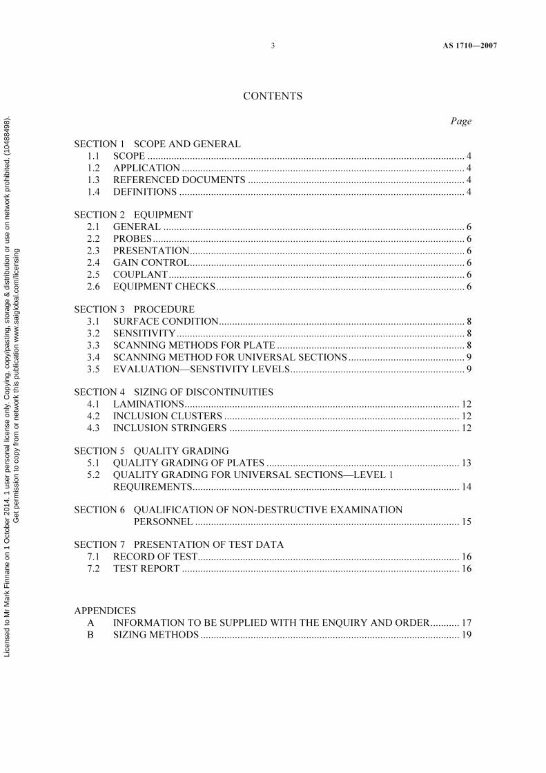
CONTENTS
Page
SECTION 1 SCOPE AND GENERAL
1.1 SCOPE ........................................................................................................................ 4
1.2 APPLICATION ........................................................................................................... 4
1.3 REFERENCED DOCUMENTS .................................................................................. 4
1.4 DEFINITIONS ............................................................................................................ 4
SECTION 2 EQUIPMENT
2.1 GENERAL .................................................................................................................. 6
2.2 PROBES...................................................................................................................... 6
2.3 PRESENTATION........................................................................................................ 6
2.4 GAIN CONTROL........................................................................................................ 6
2.5 COUPLANT................................................................................................................ 6
2.6 EQUIPMENT CHECKS.............................................................................................. 6
SECTION 3 PROCEDURE
3.1 SURFACE CONDITION............................................................................................. 8
3.2 SENSITIVITY............................................................................................................. 8
3.3 SCANNING METHODS FOR PLATE ....................................................................... 8
3.4 SCANNING METHOD FOR UNIVERSAL SECTIONS............................................ 9
3.5 EVALUATION—SENSTIVITY LEVELS.................................................................. 9
SECTION 4 SIZING OF DISCONTINUITIES
4.1 LAMINATIONS........................................................................................................ 12
4.2 INCLUSION CLUSTERS ......................................................................................... 12
4.3 INCLUSION STRINGERS ....................................................................................... 12
SECTION 5 QUALITY GRADING
5.1 QUALITY GRADING OF PLATES ......................................................................... 13
5.2 QUALITY GRADING FOR UNIVERSAL SECTIONS—LEVEL 1
REQUIREMENTS..................................................................................................... 14
SECTION 6 QUALIFICATION OF NON-DESTRUCTIVE EXAMINATION
PERSONNEL .................................................................................................... 15
SECTION 7 PRESENTATION OF TEST DATA
7.1 RECORD OF TEST................................................................................................... 16
7.2 TEST REPORT ......................................................................................................... 16
APPENDICES
A INFORMATION TO BE SUPPLIED WITH THE ENQUIRY AND ORDER........... 17
B SIZING METHODS .................................................................................................. 19
Lice
nsed
to M
r M
ark
Fin
nane
on
1 O
ctob
er 2
014.
1 u
ser
pers
onal
lice
nse
only
. Cop
ying
, cop
y/pa
stin
g, s
tora
ge &
dis
trib
utio
n or
use
on
netw
ork
proh
ibite
d. (
1048
8498
).G
et p
erm
issi
on to
cop
y fr
om o
r ne
twor
k th
is p
ublic
atio
n w
ww
.sai
glob
al.c
om/li
cens
ing

AS 1710—2007 4
Standards Australia www.standards.org.au
STANDARDS AUSTRALIA
Australian Standard
Non-destructive testing—Ultrasonic testing of carbon and low alloy steel plate and universal sections—Test methods and quality
classification
S E C T I O N 1 S C O P E A N D G E N E R A L
1.1 SCOPE
This Standard specifies the methods for the ultrasonic manual testing of carbon and low
alloy wrought steel plate of uniform thickness, in the range 5 mm to 180 mm inclusive, and
universal sections using A-scan presentation. It also classifies plate quality and defines one
quality for universal sections (Level 1) in determining freedom from discontinuities.
NOTE: For guidance for the information to be supplied with the enquiry and order, refer to
Appendix A.
1.2 APPLICATION
This Standard applies to the testing of steel plate and universal sections for general internal
quality, using methods which specify scanning to a designated scanning system. The
procedures described in this Standard enable the test operator to detect ‘laminar’ and
‘inclusion cluster’ type discontinuities. It also defines universal sections in terms of
freedom from discontinuities. Section 5 allows the specifications of three quality levels for
the body of the plate and one quality level for the edge zone.
1.3 REFERENCED DOCUMENTS
The following documents are referred to in this Standard.
AS
1929 Non-destructive testing—Glossary of terms
2083 Calibration blocks and their methods of use in ultrasonic testing
3998 Non-destructive testing—Qualification and certification of personnel
4635 Non-destructive testing—Qualification of personnel for limited applications of
non-destructive testing
1.4 DEFINITIONS
For the purpose of this Standard, the definitions given in AS 1929 and the following apply:
1.4.1 Discontinuity indications
The appearance of an echo on the flaw detector screen (using ‘A’ scan presentation)
between the surface position and the back echo position or a reduction of the original back
echo. Lice
nsed
to M
r M
ark
Fin
nane
on
1 O
ctob
er 2
014.
1 u
ser
pers
onal
lice
nse
only
. Cop
ying
, cop
y/pa
stin
g, s
tora
ge &
dis
trib
utio
n or
use
on
netw
ork
proh
ibite
d. (
1048
8498
).G
et p
erm
issi
on to
cop
y fr
om o
r ne
twor
k th
is p
ublic
atio
n w
ww
.sai
glob
al.c
om/li
cens
ing

5 AS 1710—2007
www.standards.org.au Standards Australia
1.4.2 Inclusion cluster
At the evaluation sensitivity levels specified in Clause 3.5, a discontinuity is termed an
inclusion cluster if individual discontinuity echoes are at least 50 percent of the reduced
back echo, or cause at least 50 percent reduction in the back echo obtained from a
discontinuity free area of the plate.
1.4.3 Inclusion stringers
A discontinuity producing a linear indication of the inclusion cluster type for which any
movement of the probe transverse to the direction of rolling causes a loss of indication.
1.4.4 Lamination
At the sensitivity levels specified in Clause 3.5, any discontinuity causing total reflection of
acoustic energy for a probe movement of 5 mm or greater in a direction transverse to the
major dimension of discontinuity.
1.4.5 Significant discontinuity
At the evaluation sensitivity levels specified in Clause 3.5, any lamination or inclusion
cluster type discontinuity (see Clauses 1.4.4 and 1.4.2) with an estimated area equal to or
greater than that specified in Tables 5.2 and 5.3 for the applicable quality level.
Lice
nsed
to M
r M
ark
Fin
nane
on
1 O
ctob
er 2
014.
1 u
ser
pers
onal
lice
nse
only
. Cop
ying
, cop
y/pa
stin
g, s
tora
ge &
dis
trib
utio
n or
use
on
netw
ork
proh
ibite
d. (
1048
8498
).G
et p
erm
issi
on to
cop
y fr
om o
r ne
twor
k th
is p
ublic
atio
n w
ww
.sai
glob
al.c
om/li
cens
ing

AS 1710—2007 6
Standards Australia www.standards.org.au
S E C T I O N 2 E Q U I P M E N T
2.1 GENERAL
The ultrasonic testing system shall be capable of displaying the presence of discontinuities
described in this Standard and of delineation of boundary contours of discontinuities of the
plane of the plate, or web or flange of the universal section.
2.2 PROBES
2.2.1 General
Normal compression probes designed to operate at frequencies nominally within the range
of 2 MHz to 5 MHz shall be used. For scanning and evaluation, the probes shall be either
twin or single crystal as specified in Table 2.1.
TABLE 2.1
TYPES OF PROBES USED FOR TESTING
Material thickness
mm
Probe type and frequency
≥5 ≤15 Twin 4 MHz to 5 MHz
>15 ≤40 Twin or single 2 MHz to 4 MHz
>40 ≤180 Single 2 MHz to 3 MHz
2.2.2 Protective diaphragms
Single probes used for contact testing may be fitted with a protective diaphragm, provided
that adequate sensitivity and resolution are retained.
2.2.3 Probe size
Areas of individual transmitters or receivers shall be—
(a) >50 mm2 <350 mm
2 for twin probes; and
(b) >300 mm2 <650 mm
2 for single probes.
2.3 PRESENTATION
A scan presentation shall be used.
2.4 GAIN CONTROL
A gain control calibrated in steps not exceeding 2 dB shall be used for measuring the ratios
of ultrasonic amplitudes. Suppression should not be used. If used, its effect on vertical and
horizontal linearity shall be known and recorded.
2.5 COUPLANT
A couplant with good wetting characteristics and compatible with the steel under test shall
be used.
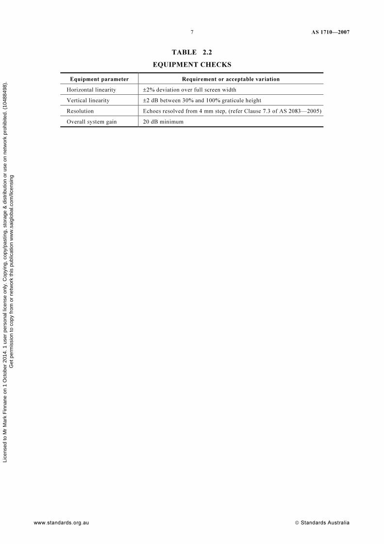
2.6 EQUIPMENT CHECKS
The equipment parameters in Table 2.2 shall be checked in accordance with AS 2083.
Lice
nsed
to M
r M
ark
Fin
nane
on
1 O
ctob
er 2
014.
1 u
ser
pers
onal
lice
nse
only
. Cop
ying
, cop
y/pa
stin
g, s
tora
ge &
dis
trib
utio
n or
use
on
netw
ork
proh
ibite
d. (
1048
8498
).G
et p
erm
issi
on to
cop
y fr
om o
r ne
twor
k th
is p
ublic
atio
n w
ww
.sai
glob
al.c
om/li
cens
ing
7 AS 1710—2007
www.standards.org.au Standards Australia
TABLE 2.2
EQUIPMENT CHECKS
Equipment parameter Requirement or acceptable variation
Horizontal linearity ±2% deviation over full screen width
Vertical linearity ±2 dB between 30% and 100% graticule height
Resolution Echoes resolved from 4 mm step, (refer Clause 7.3 of AS 2083—2005)
Overall system gain 20 dB minimum
Lice
nsed
to M
r M
ark
Fin
nane
on
1 O
ctob
er 2
014.
1 u
ser
pers
onal
lice
nse
only
. Cop
ying
, cop
y/pa
stin
g, s
tora
ge &
dis
trib
utio
n or
use
on
netw
ork
proh
ibite
d. (
1048
8498
).G
et p
erm
issi
on to
cop
y fr
om o
r ne
twor
k th
is p
ublic
atio
n w
ww
.sai
glob
al.c
om/li
cens
ing

AS 1710—2007 8
Standards Australia www.standards.org.au
S E C T I O N 3 P R O C E D U R E
3.1 SURFACE CONDITION
The surface condition of the material under test shall be such that uniform coupling is
achieved over the scanned area.
3.2 SENSITIVITY
Reference sensitivity shall be at least equal to the evaluation sensitivity required for the
plate thickness range being tested. Scanning sensitivity shall be reference sensitivity plus at
least 6 dB.
3.3 SCANNING METHODS FOR PLATE
3.3.1 Direction scanning
Scanning shall be transverse to the rolling direction of the plate.
NOTES:
1 Longitudinal scanning may be performed by agreement. (See Paragraph A2 of Appendix A).
2 When the direction of plate rolling is not known, scanning should be carried out in two
directions mutually perpendicular at intervals specified in Clause 3.3.2.
3.3.2 Scans transverse to plate rolling direction
Scanning shall be carried out at intervals appropriate to the quality grading as follows:
(a) Level 1—at 75 mm centres.
(b) Level 2—at 100 mm centres.
(c) Level 3—at 150 mm centres.
3.3.3 Scans longitudinal to plate rolling direction
When required, scanning shall be carried out at intervals appropriate to the quality grading
as follows:
NOTE: For information to be supplied when ordering refer to Appendix A, Paragraph A2.
(a) Levels 1 and 2—at 50 mm centres.
(b) Level 3—at 100 mm centres.
3.3.4 Plate edges
3.3.4.1 Trimmed edges (sheared, slit or gas cut)
For all quality levels, scanning along the plate edges shall be in a continuous band within
25 mm of the trimmed edges.
3.3.4.2 Untrimmed edges (universal or mill edge)
Where plates are ordered with untrimmed edges (universal or mill edge), supplementary
edge scanning may still be carried out. The first 25 mm from the untrimmed edge or half the
plate thickness up to a maximum of 50 mm would not be certified. The next 25 mm would
be tested as specified in Clause 3.3.4.1. Lice
nsed
to M
r M
ark
Fin
nane
on
1 O
ctob
er 2
014.
1 u
ser
pers
onal
lice
nse
only
. Cop
ying
, cop
y/pa
stin
g, s
tora
ge &
dis
trib
utio
n or
use
on
netw
ork
proh
ibite
d. (
1048
8498
).G
et p
erm
issi
on to
cop
y fr
om o
r ne
twor
k th
is p
ublic
atio
n w
ww
.sai
glob
al.c
om/li
cens
ing

9 AS 1710—2007
www.standards.org.au Standards Australia
3.4 SCANNING METHOD FOR UNIVERSAL SECTIONS
3.4.1 Extent of scanning
Testing shall be carried out on the outer faces of the two flanges and from one face of the
web. Testing of the web flange junction from the web face is not practical due to the size of
the root radius between the web and the flange.
3.4.2 Scans
Scanning shall be full width traverses, perpendicular to the direction of rolling, at each end
of the universal section. The centre-line of the end scan shall be less than 2t from the end of
the universal section and then at 150 mm intervals on the web and flanges for a minimum
distance of 1200 mm, from each end of the universal section, refer to Figure 3.1. In addition
a full longitudinal scan of both web/flange junctions shall be made along the flange faces
for a minimum distance of 1200 mm from each end.
The detection of limited discontinuities in the web shall not include the zone within one
half of the probe face dimensions from the commencement of the radius. Scanning shall
extend to the edges of the universal section. However, the detection of limiting
discontinuities in the universal section shall not include the edge zone within one half of the
probe face dimension.
Spacing 150 mm for1200 mm from each end
1200 mm
2 t
Full scan of junction for1200 mm from each end
t
FIGURE 3.1 SCANNING PATTERN
3.5 EVALUATION—SENSTIVITY LEVELS
3.5.1 General
Classification of discontinuities and the delineation of their boundaries shall be performed
at the sensitivity levels specified for the relevant plate thickness ranges in Clauses 3.5.2,
3.5.3 and 3.5.4. Sensitivity levels shall be set at a discontinuity free area of the plate or
universal section under test.
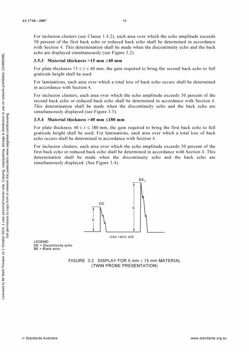
3.5.2 Material thickness ≥5 mm ≤15 mm
For material thickness 5 ≤ t ≤ 15 mm, the gain required to bring the first back echo to full
graticule height shall be used. For laminations (see Clause 1.4.4), each area over which a
total loss of back echo occurs shall be determined in accordance with Section 4.
Lice
nsed
to M
r M
ark
Fin
nane
on
1 O
ctob
er 2
014.
1 u
ser
pers
onal
lice
nse
only
. Cop
ying
, cop
y/pa
stin
g, s
tora
ge &
dis
trib
utio
n or
use
on
netw
ork
proh
ibite
d. (
1048
8498
).G
et p
erm
issi
on to
cop
y fr
om o
r ne
twor
k th
is p
ublic
atio
n w
ww
.sai
glob
al.c
om/li
cens
ing
AS 1710—2007 10
Standards Australia www.standards.org.au
For inclusion clusters (see Clause 1.4.2), each area over which the echo amplitude exceeds
50 percent of the first back echo or reduced back echo shall be determined in accordance
with Section 4. This determination shall be made when the discontinuity echo and the back
echo are displayed simultaneously (see Figure 3.2).
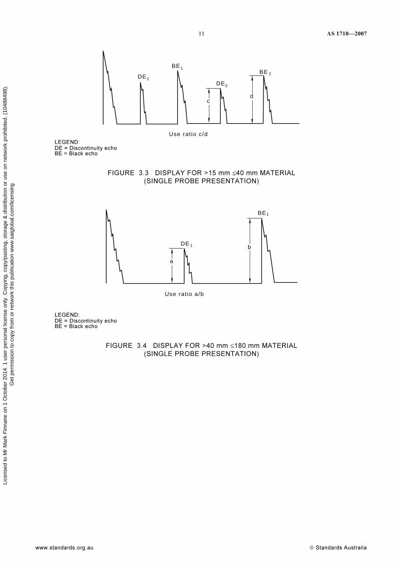
3.5.3 Material thickness >15 mm ≤40 mm
For plate thickness 15 ≤ t ≤ 40 mm, the gain required to bring the second back echo to full
graticule height shall be used.
For laminations, each area over which a total loss of back echo occurs shall be determined
in accordance with Section 4.
For inclusion clusters, each area over which the echo amplitude exceeds 50 percent of the
second back echo or reduced back echo shall be determined in accordance with Section 4.
This determination shall be made when the discontinuity echo and the back echo are
simultaneously displayed (see Figure 3.3).
3.5.4 Material thickness >40 mm ≤180 mm
For plate thickness 40 ≤ t ≤ 180 mm, the gain required to bring the first back echo to full
graticule height shall be used. For laminations, each area over which a total loss of back
echo occurs shall be determined in accordance with Section 4.
For inclusion clusters, each area over which the echo amplitude exceeds 50 percent of the
first back echo or reduced back echo shall be determined in accordance with Section 4. This
determination shall be made when the discontinuity echo and the back echo are
simultaneously displayed. (See Figure 3.4).
DE
BE
Use rat io a/b
a
b
1
LEGEND: DE = Discontinuity echo BE = Black echo
FIGURE 3.2 DISPLAY FOR 5 mm ≤ 15 mm MATERIAL
(TWIN PROBE PRESENTATION)
Lice
nsed
to M
r M
ark
Fin
nane
on
1 O
ctob
er 2
014.
1 u
ser
pers
onal
lice
nse
only
. Cop
ying
, cop
y/pa
stin
g, s
tora
ge &
dis
trib
utio
n or
use
on
netw
ork
proh
ibite
d. (
1048
8498
).G
et p
erm
issi
on to
cop
y fr
om o
r ne
twor
k th
is p
ublic
atio
n w
ww
.sai
glob
al.c
om/li
cens
ing
11 AS 1710—2007
www.standards.org.au Standards Australia
Use rat io c/d
d
DEDE
BEBE
c
1
1
2
2
LEGEND: DE = Discontinuity echo BE = Black echo
FIGURE 3.3 DISPLAY FOR >15 mm ≤40 mm MATERIAL
(SINGLE PROBE PRESENTATION)
Use rat io a/b
DE
BE
a
b1
1
LEGEND: DE = Discontinuity echo BE = Black echo
FIGURE 3.4 DISPLAY FOR >40 mm ≤180 mm MATERIAL
(SINGLE PROBE PRESENTATION)
Lice
nsed
to M
r M
ark
Fin
nane
on
1 O
ctob
er 2
014.
1 u
ser
pers
onal
lice
nse
only
. Cop
ying
, cop
y/pa
stin
g, s
tora
ge &
dis
trib
utio
n or
use
on
netw
ork
proh
ibite
d. (
1048
8498
).G
et p
erm
issi
on to
cop
y fr
om o
r ne
twor
k th
is p
ublic
atio
n w
ww
.sai
glob
al.c
om/li
cens
ing

AS 1710—2007 12
Standards Australia www.standards.org.au
S E C T I O N 4 S I Z I N G O F D I S C O N T I N U I T I E S
4.1 LAMINATIONS
The area of laminations shall be determined by the ‘6 dB drop’ method in accordance with
Appendix B.
When the twin crystal probes are used for delineating areas of laminations, the acoustics
separation barrier shall be at right angles to the discontinuity boundary.
4.2 INCLUSION CLUSTERS
The area of inclusion clusters shall be determined by the ‘last significant echo’ method in
accordance with Appendix B.
4.3 INCLUSION STRINGERS
The length of the inclusion stringers shall be determined by the ‘6 dB drop’ method in
accordance with Appendix B.
Lice
nsed
to M
r M
ark
Fin
nane
on
1 O
ctob
er 2
014.
1 u
ser
pers
onal
lice
nse
only
. Cop
ying
, cop
y/pa
stin
g, s
tora
ge &
dis
trib
utio
n or
use
on
netw
ork
proh
ibite
d. (
1048
8498
).G
et p
erm
issi
on to
cop
y fr
om o
r ne
twor
k th
is p
ublic
atio
n w
ww
.sai
glob
al.c
om/li
cens
ing
13 AS 1710—2007
www.standards.org.au Standards Australia
S E C T I O N 5 Q U A L I T Y G R A D I N G
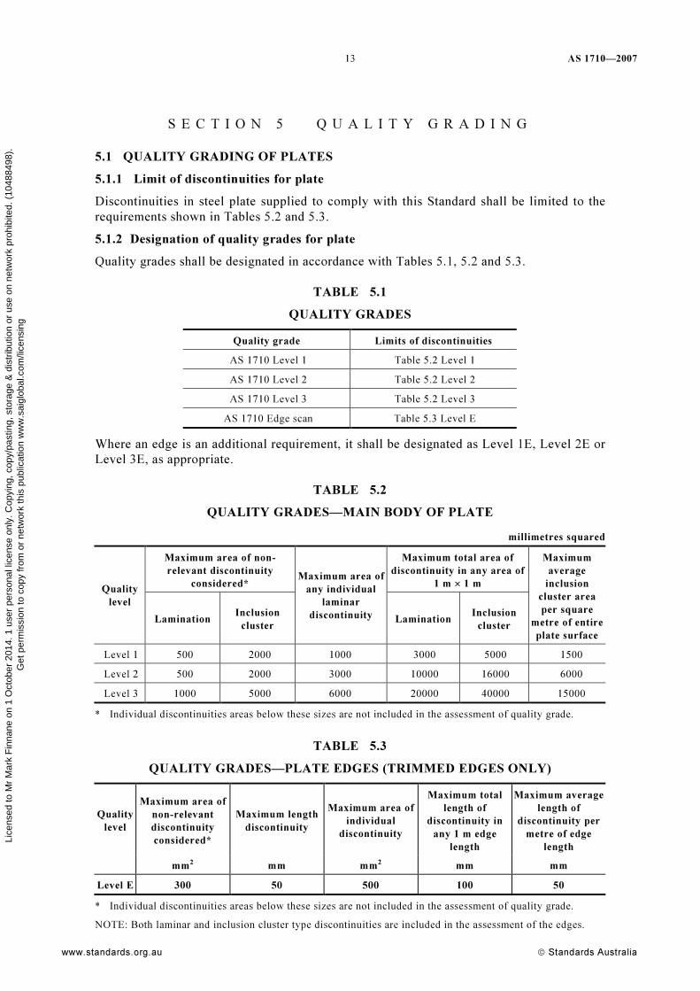
5.1 QUALITY GRADING OF PLATES
5.1.1 Limit of discontinuities for plate
Discontinuities in steel plate supplied to comply with this Standard shall be limited to the
requirements shown in Tables 5.2 and 5.3.
5.1.2 Designation of quality grades for plate
Quality grades shall be designated in accordance with Tables 5.1, 5.2 and 5.3.
TABLE 5.1
QUALITY GRADES
Quality grade Limits of discontinuities
AS 1710 Level 1 Table 5.2 Level 1
AS 1710 Level 2 Table 5.2 Level 2
AS 1710 Level 3 Table 5.2 Level 3
AS 1710 Edge scan Table 5.3 Level E
Where an edge is an additional requirement, it shall be designated as Level 1E, Level 2E or
Level 3E, as appropriate.
TABLE 5.2
QUALITY GRADES—MAIN BODY OF PLATE
millimetres squared
Maximum area of non-
relevant discontinuity
considered*
Maximum total area of
discontinuity in any area of
1 m × 1 m Quality
level
Lamination Inclusion
cluster
Maximum area of
any individual
laminar
discontinuity Lamination Inclusion
cluster
Maximum
average
inclusion
cluster area
per square
metre of entire
plate surface
Level 1 500 2000 1000 3000 5000 1500
Level 2 500 2000 3000 10000 16000 6000
Level 3 1000 5000 6000 20000 40000 15000
* Individual discontinuities areas below these sizes are not included in the assessment of quality grade.
TABLE 5.3
QUALITY GRADES—PLATE EDGES (TRIMMED EDGES ONLY)
Quality
level
Maximum area of
non-relevant
discontinuity
considered*
Maximum length
discontinuity
Maximum area of
individual
discontinuity
Maximum total
length of
discontinuity in
any 1 m edge
length
Maximum average
length of
discontinuity per
metre of edge
length
mm2 mm mm2 mm mm
Level E 300 50 500 100 50
* Individual discontinuities areas below these sizes are not included in the assessment of quality grade.
NOTE: Both laminar and inclusion cluster type discontinuities are included in the assessment of the edges.
Lice
nsed
to M
r M
ark
Fin
nane
on
1 O
ctob
er 2
014.
1 u
ser
pers
onal
lice
nse
only
. Cop
ying
, cop
y/pa
stin
g, s
tora
ge &
dis
trib
utio
n or
use
on
netw
ork
proh
ibite
d. (
1048
8498
).G
et p
erm
issi
on to
cop
y fr
om o
r ne
twor
k th
is p
ublic
atio
n w
ww
.sai
glob
al.c
om/li
cens
ing

AS 1710—2007 14
Standards Australia www.standards.org.au
5.2 QUALITY GRADING FOR UNIVERSAL SECTIONS—LEVEL 1
REQUIREMENTS
5.2.1 Laminar discontinuities
To comply with Level 1 requirements, the universal section shall be free from laminar
discontinuities for a distance of 450 mm from each end. The remaining length shall not
contain laminar discontinuities 250 mm2 or greater in area. In addition, where a laminar
type discontinuity is detected in the web and extends into the flange area (where proper
assessment of its area cannot be carried out) the area of the universal section affected with
the lamination shall not comply with Level 1.
5.2.2 Inclusion discontinuities
For inclusion discontinuities, the universal section shall be assessed over the length tested.
The area of inclusion stringers shall be its measured length (in millimetres) multiplied by
2 mm.
Only inclusion clusters and stringers in excess of 600 mm2 area shall be considered.
5.2.3 Level 1 requirements
The total discontinuity area shall be the sum of—
(a) laminar discontinuities less than 250 mm2; and
(b) inclusion discontinuities exceeding 600 mm2.
The total area of discontinuities to area tested ratio shall not exceed 1:80 for each flange
face and web face.
Lice
nsed
to M
r M
ark
Fin
nane
on
1 O
ctob
er 2
014.
1 u
ser
pers
onal
lice
nse
only
. Cop
ying
, cop
y/pa
stin
g, s
tora
ge &
dis
trib
utio
n or
use
on
netw
ork
proh
ibite
d. (
1048
8498
).G
et p
erm
issi
on to
cop
y fr
om o
r ne
twor
k th
is p
ublic
atio
n w
ww
.sai
glob
al.c
om/li
cens
ing

15 AS 1710—2007
www.standards.org.au Standards Australia
S E C T I O N 6 Q U A L I F I C A T I O N O F N O N -
D E S T R U C T I V E E X A M I N A T I O N P E R S O N N E L
Ultrasonic examination, interpretation, evaluation for compliance, and report shall be made
by personnel having qualifications and experience for their job function acceptable to the
testing body, the manufacturer and where required by the purchaser.
Operators shall have the qualifications detailed below or shall carry out their duties under
the supervision of persons responsible for examination.
Qualifications normally acceptable for the examination of components include the
following:
(a) Certification by the Australian Institute for Non-Destructive Testing (AINDT
Certification Board) in accordance with AS 3998 or AS 4635 for ultrasonic thickness
testing.
(b) Equivalent qualifications.
Lice
nsed
to M
r M
ark
Fin
nane
on
1 O
ctob
er 2
014.
1 u
ser
pers
onal
lice
nse
only
. Cop
ying
, cop
y/pa
stin
g, s
tora
ge &
dis
trib
utio
n or
use
on
netw
ork
proh
ibite
d. (
1048
8498
).G
et p
erm
issi
on to
cop
y fr
om o
r ne
twor
k th
is p
ublic
atio
n w
ww
.sai
glob
al.c
om/li
cens
ing
AS 1710—2007 16
Standards Australia www.standards.org.au
S E C T I O N 7 P R E S E N T A T I O N O F T E S T D A T A
7.1 RECORD OF TEST
A record of results shall be made, and shall provide the following information:
(a) Name of laboratory or testing authority.
(b) Identification of the plate or universal section and job reference.
(c) Plate or universal section identification and product standard.
(d) Material designation according to relevant material specification.
(e) Surface condition.
(f) Number of this Australian Standard, i.e. AS 1710, and the scanning pattern used and
evaluation level (see Clauses 3.3, 3.4 and 3.5).
(g) Equipment, probe type and couplant.
(h) Extent and location of nominated areas inspected.
(i) Where recordable discontinuities are detected, a plan view showing location, outline
area and identification of discontinuities, plus the test datum point.
(j) Date and place of test.
(k) Report number and date of issue.
(l) Any other information specified and agreed between supplier and purchaser.
(m) Name of certified operator.
7.2 TEST REPORT
Test reports shall contain the following information:
(a) Name of the laboratory or testing authority.
(b) Identification of the plate or universal section and job reference number.
(c) Plate or universal section identification and product standard.
(d) Material designation according to relevant material specification.
(e) Surface condition.
(f) Number of this Australian Standard, i.e. AS 1710, and scanning pattern used and
evaluation level (see Clause 3.3, 3.4 and 3.5).
(g) Where recordable discontinuities are detected, a plan view showing location, outline
area and identification of discontinuities, plus the test datum point.
(h) Date and place of test.
(i) Report number and date of issue.
(j) Any other information specified and agreed between supplier and purchaser.
(k) Name of certified operator. Lice
nsed
to M
r M
ark
Fin
nane
on
1 O
ctob
er 2
014.
1 u
ser
pers
onal
lice
nse
only
. Cop
ying
, cop
y/pa
stin
g, s
tora
ge &
dis
trib
utio
n or
use
on
netw
ork
proh
ibite
d. (
1048
8498
).G
et p
erm
issi
on to
cop
y fr
om o
r ne
twor
k th
is p
ublic
atio
n w
ww
.sai
glob
al.c
om/li
cens
ing

17 AS 1710—2007
www.standards.org.au Standards Australia
APPENDIX A
INFORMATION TO BE SUPPLIED WITH THE ENQUIRY AND ORDER
(Informative)
A1 GENERAL
This Appendix contains advice, and recommendations on the information to be supplied by
the purchaser at the time of enquiry or order.
A2 INFORMATION TO BE SUPPLIED WHEN ORDERING PLATE
The purchaser should supply the following information with inquiry and order of plate.
(a) The number of this Australian Standard, i.e. AS 1710 and the quality grade to be
achieved for main body of plate and edges (see Clause 5.1).
(b) Identification of plate, to include:
(i) Serial number (where available).
(ii) Plate dimensions (nominal ordered).
(iii) Edge condition (mill edge, universal edge, or trimmed edge).
(iv) Material specification.
(c) Whether a longitudinal scan is required (see Clause 3.3.3).
(d) Any departure from test method outlined in this Standard.
(e) Whether a test report is required (see Clause 7.2).
A3 DIRECTION OF SCANNING
This Standard requires the scanning of plate to be carried out in a directions transverse to
the direction of rolling.
Scanning in a longitudinal direction, i.e. parallel to the direction of rolling may only be
carried out by agreement between the manufacturer and the purchaser, and must be agreed
on at the time of placing the order.
When the direction of rolling is not known, scanning must be carried out in both direction
to ensure that at least one direction of scan is transverse to the rolling direction.
A4 REFEREE TESTING
Where disputes arise between the purchaser and the supplier regarding the compliance of
the product with this Standard and the need for referee testing becomes apparent; the
purchaser and supplier should agree on a testing procedure. The probes that should be used
for referee testing are listed as follows:
Material thickness, mm Probe type and frequency
≥5 ≤15 Twin 4 MHz
≥15 ≤40 Single 4 MHz
≥40 ≤180 Single 2 MHz
Lice
nsed
to M
r M
ark
Fin
nane
on
1 O
ctob
er 2
014.
1 u
ser
pers
onal
lice
nse
only
. Cop
ying
, cop
y/pa
stin
g, s
tora
ge &
dis
trib
utio
n or
use
on
netw
ork
proh
ibite
d. (
1048
8498
).G
et p
erm
issi
on to
cop
y fr
om o
r ne
twor
k th
is p
ublic
atio
n w
ww
.sai
glob
al.c
om/li
cens
ing

AS 1710—2007 18
Standards Australia www.standards.org.au
A5 INFORMATION TO BE SUPPLIED WHEN ORDERING UNIVERSAL
SECTIONS
The purchaser should supply the following information with the inquiry and order of
universal sections.
(a) The number of this Australian Standard, i.e. AS 1710.
(b) Identification of section to include:
(i) Serial number (where available).
(ii) Universal section dimensions (nominal ordered).
(iii) Material specification.
(c) Any departure from test methods outlined in this Standard.
(d) Whether a test report is required.
(e) This Standard requires scanning to be carried out at the extremities of the universal
section. Should the purchaser require additional regions of the beam or column to be
examined, then this should be specified at the time of order.
Lice
nsed
to M
r M
ark
Fin
nane
on
1 O
ctob
er 2
014.
1 u
ser
pers
onal
lice
nse
only
. Cop
ying
, cop
y/pa
stin
g, s
tora
ge &
dis
trib
utio
n or
use
on
netw
ork
proh
ibite
d. (
1048
8498
).G
et p
erm
issi
on to
cop
y fr
om o
r ne
twor
k th
is p
ublic
atio
n w
ww
.sai
glob
al.c
om/li
cens
ing

19 AS 1710—2007
www.standards.org.au Standards Australia
APPENDIX B
SIZING METHODS
(Normative)
B1 PROCEDURE FOR SIZING LAMINATIONS USING 6 dB DROP TECHNIQUE
The procedure for sizing shall be as follows:
(a) Move probe over discontinuity to obtain a maximum from the last significant echo
(see Figure B1).
(b) At this point, adjust the gain to obtain an echo between 80 percent and 100 percent
graticule height (see Figure B2).
(c) Decrease gain by 6 dB and note echo height (see Figure B3).
(d) Return gain to original setting
(e) Move probe over edge of discontinuity until the echo is reduced to the level noted in
Step (c) (see Figure B4).
(f) Mark positions of centre-line of the probe. (This will be the edge of the
discontinuity).
B2 PROCEDURE FOR SIZING INCLUSION CLUSTER DISCONTINUITIES
USING THE LAST SIGNIFICANT ECHO TECHNIQUE
The procedure shall be as follows:
(a) Move probe over discontinuity until the last significant echo is obtained (see Figure
B1).
(b) Continue to move probe towards edge of discontinuity area until the echo just starts
to decrease in amplitude.
(c) Mark position of the centre-line of probe. (This will be edge of the discontinuity area
for evaluation purposes).
FIGURE B1 POINT AT LAST SIGNIFICANT ECHO
Lice
nsed
to M
r M
ark
Fin
nane
on
1 O
ctob
er 2
014.
1 u
ser
pers
onal
lice
nse
only
. Cop
ying
, cop
y/pa
stin
g, s
tora
ge &
dis
trib
utio
n or
use
on
netw
ork
proh
ibite
d. (
1048
8498
).G
et p
erm
issi
on to
cop
y fr
om o
r ne
twor
k th
is p
ublic
atio
n w
ww
.sai
glob
al.c
om/li
cens
ing

AS 1710—2007 20
Standards Australia www.standards.org.au
x
FIGURE B2 ECHO AT 80 – 100 PERCENT
x-6dB
FIGURE B3 6 dB DOWN FROM SIGNAL IN FIGURE B2
FIGURE B4 PROBE POSITION 6 dB DOWN ON DISCONTINUITY
Lice
nsed
to M
r M
ark
Fin
nane
on
1 O
ctob
er 2
014.
1 u
ser
pers
onal
lice
nse
only
. Cop
ying
, cop
y/pa
stin
g, s
tora
ge &
dis
trib
utio
n or
use
on
netw
ork
proh
ibite
d. (
1048
8498
).G
et p
erm
issi
on to
cop
y fr
om o
r ne
twor
k th
is p
ublic
atio
n w
ww
.sai
glob
al.c
om/li
cens
ing

Standards AustraliaStandards AustraliaStandards AustraliaStandards Australia Standards Australia develops Australian Standards® and other documents of public benefit and national interest. These Standards are developed through an open process of consultation and consensus, in which all interested parties are invited to participate. Through a Memorandum of Understanding with the Commonwealth Government, Standards Australia is recognized as Australia’s peak non-government national standards body. Standards Australia also supports excellence in design and innovation through the Australian Design Awards. For further information visit www.standards.org.auwww.standards.org.auwww.standards.org.auwww.standards.org.au AustAustAustAustralian Standardsralian Standardsralian Standardsralian Standards®®®® Committees of experts from industry, governments, consumers and other relevant sectors prepare Australian Standards. The requirements or recommendations contained in published Standards are a consensus of the views of representative interests and also take account of comments received from other sources. They reflect the latest scientific and industry experience. Australian Standards are kept under continuous review after publication and are updated regularly to take account of changing technology. International InvolvementInternational InvolvementInternational InvolvementInternational Involvement Standards Australia is responsible for ensuring the Australian viewpoint is considered in the formulation of International Standards and that the latest international experience is incorporated in national Standards. This role is vital in assisting local industry to compete in international markets. Standards Australia represents Australia at both the International Organization for Standardization (ISO) and the International Electrotechnical Commission (IEC). Sales and Sales and Sales and Sales and DistributionDistributionDistributionDistribution Australian Standards®, Handbooks and other documents developed by Standards Australia are printed and distributed under license by SAI Global Limited.
Lice
nsed
to M
r M
ark
Fin
nane
on
1 O
ctob
er 2
014.
1 u
ser
pers
onal
lice
nse
only
. Cop
ying
, cop
y/pa
stin
g, s
tora
ge &
dis
trib
utio
n or
use
on
netw
ork
proh
ibite
d. (
1048
8498
).G
et p
erm
issi
on to
cop
y fr
om o
r ne
twor
k th
is p
ublic
atio
n w
ww
.sai
glob
al.c
om/li
cens
ing

For information regarding the development of Standards contact: Standards Australia Limited GPO Box 476 Sydney NSW 2001 Phone: 02 8206 6000 Fax: 02 8206 6001 Email: [email protected] Internet: www.standards.org.au For information regarding the sale and distribution of Standards contact: SAI Global Limited Phone: 13 12 42 Fax: 1300 65 49 49 Email: [email protected]
ISBN 0 7337 7994 8
Lice
nsed
to M
r M
ark
Fin
nane
on
1 O
ctob
er 2
014.
1 u
ser
pers
onal
lice
nse
only
. Cop
ying
, cop
y/pa
stin
g, s
tora
ge &
dis
trib
utio
n or
use
on
netw
ork
proh
ibite
d. (
1048
8498
).G
et p
erm
issi
on to
cop
y fr
om o
r ne
twor
k th
is p
ublic
atio
n w
ww
.sai
glob
al.c
om/li
cens
ing