
LI-ION BATTERY UPFIT KIT - Polaris Inc.
11
APPLICATION E2, E4, E6, and eL XD BEFORE YOU BEGIN Read these instructions and check to be sure all parts and tools are accounted for. Please retain these installation instructions for future reference and parts ordering information. KIT CONTENTS Full installation of this kit also requires the following additional parts (sold separately): • 12V Battery, PN 4014770 • Li-Ion Control Module, PN 4016692 Full installation of this kit also requires one of the following additional parts (sold separately): 12.4 kW • Brammo Battery, 15v/4.1 kW, PN 4017364 • Brammo Battery, 30v/8.3 kW, PN 4017365 8.9 kW • Brammo Battery, 44v/8.9 Kw, PN 4017366 Full installation of this kit also requires one of the following additional parts (sold separately): • Li-Ion Harness e2/eL XD, PN 2413350 • Li-Ion Harness e4, PN 2413374 • Li-Ion Harness e6, PN 2413375 Instr 9926969 Rev 02 2017-10 Page 1 of 11 P/N 2881852 LI-ION BATTERY UPFIT KIT
Transcript of LI-ION BATTERY UPFIT KIT - Polaris Inc.

APPLICATIONE2, E4, E6, and eL XD
BEFORE YOU BEGINRead these instructions and check to be sure all parts and tools are accounted for. Please retain theseinstallation instructions for future reference and parts ordering information.
KIT CONTENTSFull installation of this kit also requires the following additional parts (sold separately):• 12V Battery, PN 4014770• Li-Ion Control Module, PN 4016692
Full installation of this kit also requires one of the following additional parts (sold separately):12.4 kW• Brammo Battery, 15v/4.1 kW, PN 4017364• Brammo Battery, 30v/8.3 kW, PN 4017365
8.9 kW• Brammo Battery, 44v/8.9 Kw, PN 4017366
Full installation of this kit also requires one of the following additional parts (sold separately):• Li-Ion Harness e2/eL XD, PN 2413350• Li-Ion Harness e4, PN 2413374• Li-Ion Harness e6, PN 2413375
Instr 9926969 Rev 02 2017-10 Page 1 of 11
P/N 2881852
LI-ION BATTERY UPFIT KIT
Instr 9926969 Rev 02 2017-10 Page 2 of 11
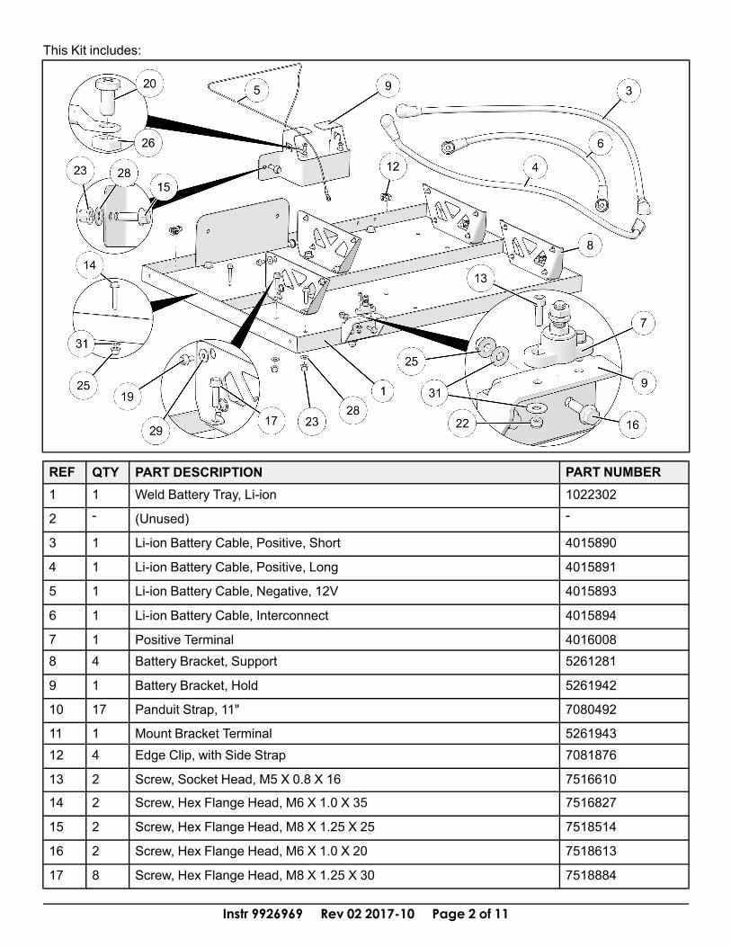
This Kit includes:
REF QTY PART DESCRIPTION PART NUMBER1 1 Weld Battery Tray, Li-ion 1022302
2 - (Unused) -
3 1 Li-ion Battery Cable, Positive, Short 4015890
4 1 Li-ion Battery Cable, Positive, Long 4015891
5 1 Li-ion Battery Cable, Negative, 12V 4015893
6 1 Li-ion Battery Cable, Interconnect 4015894
7 1 Positive Terminal 40160088 4 Battery Bracket, Support 5261281
9 1 Battery Bracket, Hold 5261942
10 17 Panduit Strap, 11" 7080492
11 1 Mount Bracket Terminal 526194312 4 Edge Clip, with Side Strap 7081876
13 2 Screw, Socket Head, M5 X 0.8 X 16 7516610
14 2 Screw, Hex Flange Head, M6 X 1.0 X 35 7516827
15 2 Screw, Hex Flange Head, M8 X 1.25 X 25 7518514
16 2 Screw, Hex Flange Head, M6 X 1.0 X 20 7518613
17 8 Screw, Hex Flange Head, M8 X 1.25 X 30 7518884
Instr 9926969 Rev 02 2017-10 Page 3 of 11
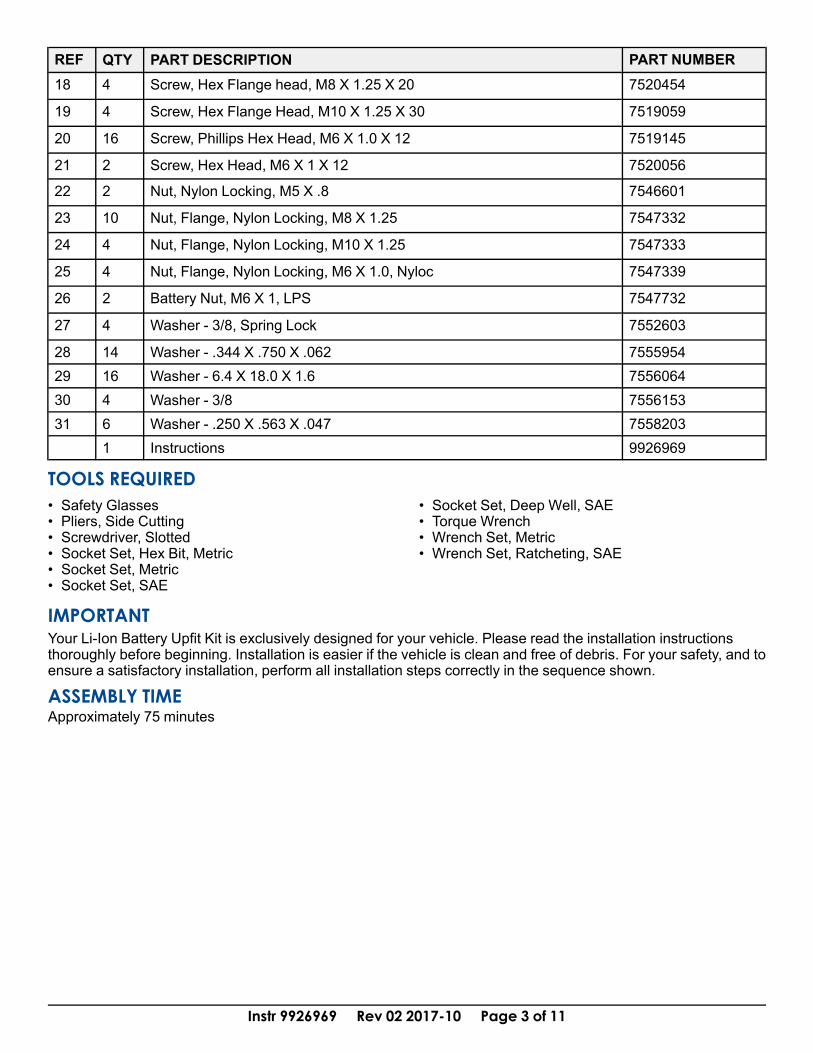
REF QTY PART DESCRIPTION PART NUMBER18 4 Screw, Hex Flange head, M8 X 1.25 X 20 7520454
19 4 Screw, Hex Flange Head, M10 X 1.25 X 30 7519059
20 16 Screw, Phillips Hex Head, M6 X 1.0 X 12 7519145
21 2 Screw, Hex Head, M6 X 1 X 12 7520056
22 2 Nut, Nylon Locking, M5 X .8 7546601
23 10 Nut, Flange, Nylon Locking, M8 X 1.25 7547332
24 4 Nut, Flange, Nylon Locking, M10 X 1.25 7547333
25 4 Nut, Flange, Nylon Locking, M6 X 1.0, Nyloc 7547339
26 2 Battery Nut, M6 X 1, LPS 7547732
27 4 Washer - 3/8, Spring Lock 7552603
28 14 Washer - .344 X .750 X .062 755595429 16 Washer - 6.4 X 18.0 X 1.6 755606430 4 Washer - 3/8 755615331 6 Washer - .250 X .563 X .047 7558203
1 Instructions 9926969
TOOLS REQUIRED• Safety Glasses• Pliers, Side Cutting• Screwdriver, Slotted• Socket Set, Hex Bit, Metric• Socket Set, Metric• Socket Set, SAE
• Socket Set, Deep Well, SAE• Torque Wrench• Wrench Set, Metric• Wrench Set, Ratcheting, SAE
IMPORTANTYour Li-Ion Battery Upfit Kit is exclusively designed for your vehicle. Please read the installation instructionsthoroughly before beginning. Installation is easier if the vehicle is clean and free of debris. For your safety, and toensure a satisfactory installation, perform all installation steps correctly in the sequence shown.
ASSEMBLY TIMEApproximately 75 minutes
Instr 9926969 Rev 02 2017-10 Page 4 of 11
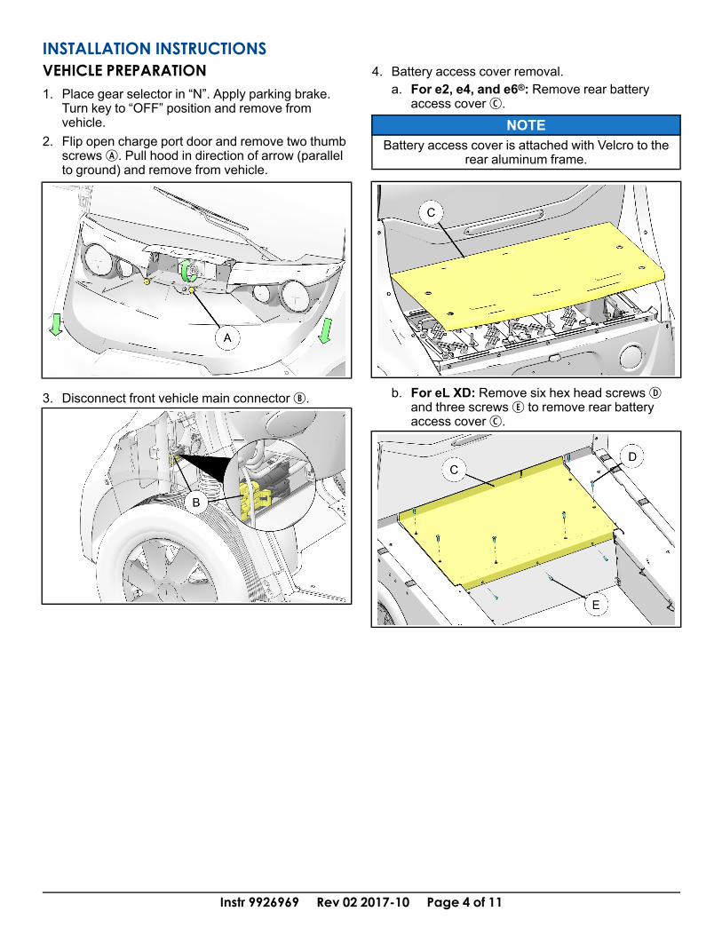
INSTALLATION INSTRUCTIONSVEHICLE PREPARATION1. Place gear selector in “N”. Apply parking brake.
Turn key to “OFF” position and remove fromvehicle.
2. Flip open charge port door and remove two thumbscrewsA. Pull hood in direction of arrow (parallelto ground) and remove from vehicle.
3. Disconnect front vehicle main connectorB.
4. Battery access cover removal.a. For e2, e4, and e6®: Remove rear battery
access coverC.
NOTEBattery access cover is attached with Velcro to the
rear aluminum frame.
b. For eL XD: Remove six hex head screwsDand three screwsE to remove rear batteryaccess coverC.
Instr 9926969 Rev 02 2017-10 Page 5 of 11
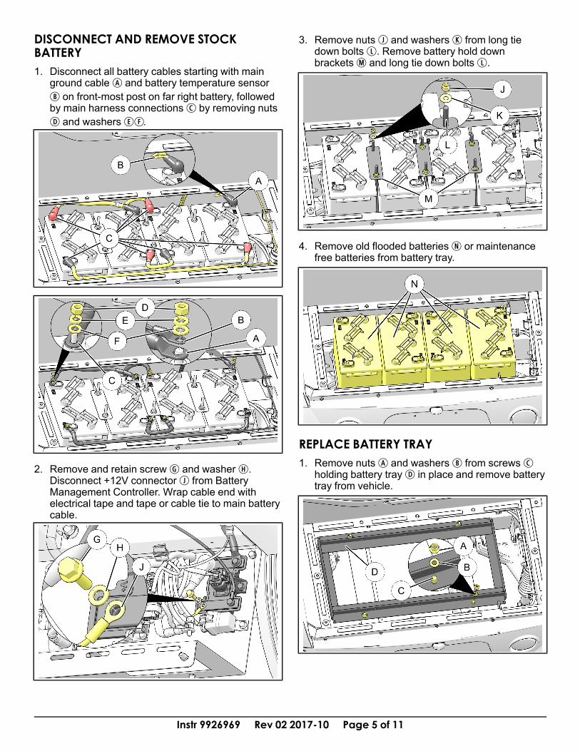
DISCONNECT AND REMOVE STOCKBATTERY1. Disconnect all battery cables starting with main
ground cableA and battery temperature sensorB on front-most post on far right battery, followedby main harness connectionsC by removing nutsD and washersEF.
2. Remove and retain screwG and washerH.Disconnect +12V connectorJ from BatteryManagement Controller. Wrap cable end withelectrical tape and tape or cable tie to main batterycable.
3. Remove nutsJ and washersK from long tiedown boltsL. Remove battery hold downbracketsM and long tie down boltsL.
4. Remove old flooded batteriesN or maintenancefree batteries from battery tray.
REPLACE BATTERY TRAY1. Remove nutsA and washersB from screwsC
holding battery trayD in place and remove batterytray from vehicle.
Instr 9926969 Rev 02 2017-10 Page 6 of 11
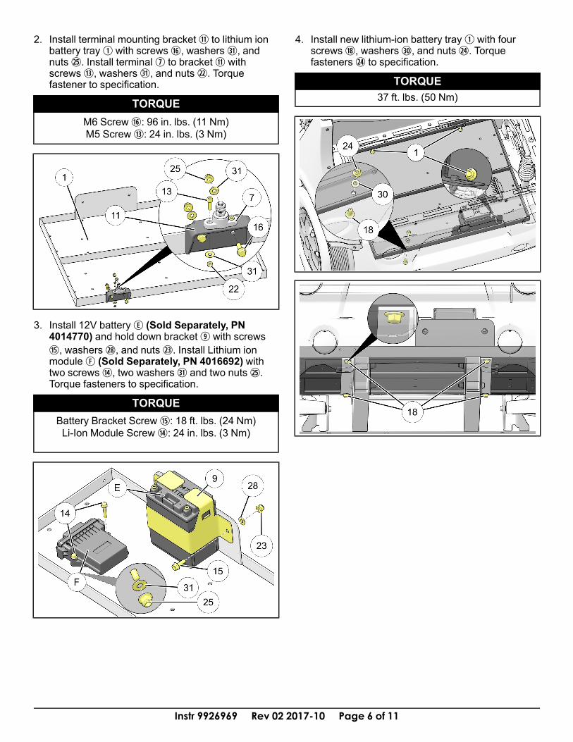
2. Install terminal mounting brackets to lithium ionbattery trayq with screwsj, washers 3!, andnuts 2%. Install terminalu to brackets withscrewsf, washers 3!, and nuts 2@. Torquefastener to specification.
TORQUEM6 Screwj: 96 in. lbs. (11 Nm)M5 Screwf: 24 in. lbs. (3 Nm)
3. Install 12V batteryE (Sold Separately, PN4014770) and hold down bracketo with screwsh, washers 2*, and nuts 2#. Install Lithium ionmoduleF (Sold Separately, PN 4016692) withtwo screwsg, two washers 3! and two nuts 2%.Torque fasteners to specification.
TORQUEBattery Bracket Screwh: 18 ft. lbs. (24 Nm)Li-Ion Module Screwg: 24 in. lbs. (3 Nm)
4. Install new lithium-ion battery trayq with fourscrewsl, washers 3), and nuts 2$. Torquefasteners 2$ to specification.
TORQUE37 ft. lbs. (50 Nm)
Instr 9926969 Rev 02 2017-10 Page 7 of 11
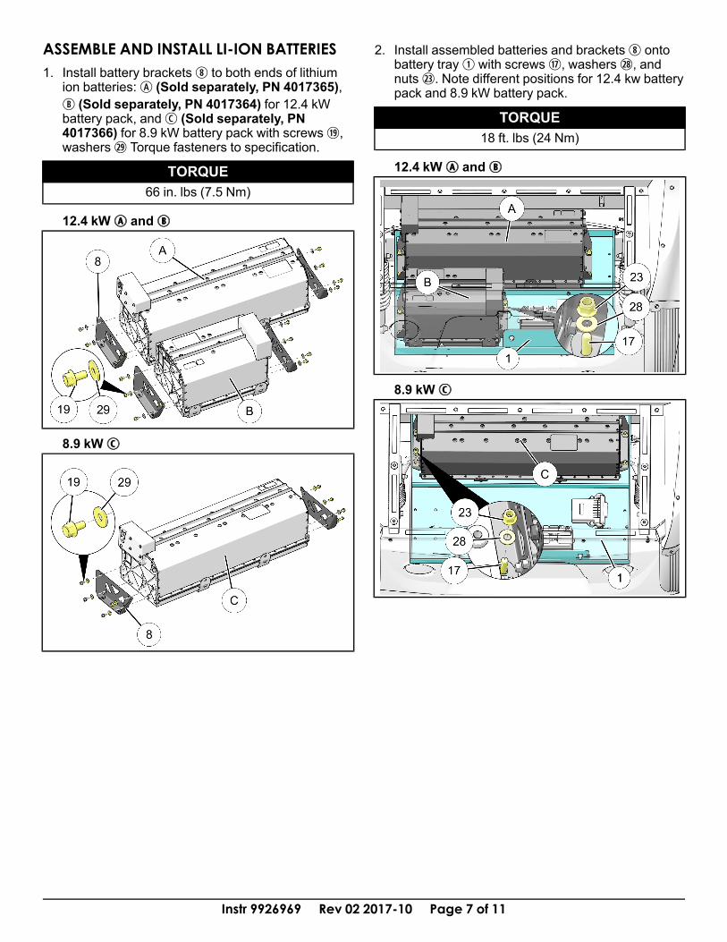
ASSEMBLE AND INSTALL LI-ION BATTERIES1. Install battery bracketsi to both ends of lithium
ion batteries:A (Sold separately, PN 4017365),B (Sold separately, PN 4017364) for 12.4 kWbattery pack, andC (Sold separately, PN4017366) for 8.9 kW battery pack with screws 1(,washers 2( Torque fasteners to specification.
TORQUE66 in. lbs (7.5 Nm)
12.4 kWAA andBB
8.9 kWCC
2. Install assembled batteries and bracketsi ontobattery trayq with screwsk, washers 2*, andnuts 2#. Note different positions for 12.4 kw batterypack and 8.9 kW battery pack.
TORQUE18 ft. lbs (24 Nm)
12.4 kWAA andBB
8.9 kWCC

Instr 9926969 Rev 02 2017-10 Page 8 of 11
CONNECT BATTERY WIRINGNOTE
Vehicle not shown for clarity.
12.4 KW BATTERY CABLES AND LI-IONHARNESS1. Install Positive Short battery cablee and positive
cable from main harnessA to positive terminalmountu. Install opposite end of Positive ShortCablee to post on small Li-Ion BatteryB. DONOT Torque battery post fasteners at this time.
WARNINGDO NOT Connect Main Harness Negative BatteryCable At This Time, or serious injury or damage
to components may occur.
2. Connect Battery Cable Interconnecty betweenbattery posts using two battery post washersCand screwsD as shown. DO NOT torque batteryconnections at this time.
3. Install appropriate Li-Ion HarnessE by plugginglarge connectorF into Li-Ion Module. Now plugconnectorG into large battery, remove blank plugfrom connectorH and plug into small battery.Connect small cableJ to positive battery terminalon small battery. Torque ALL already connectedbattery terminal connectors to specification.
WARNINGDO NOT Connect Main Harness Negative BatteryCable At This Time, or serious injury or damage
to components may occur.
TORQUE8 ft. lbs. (11 Nm)
8.9 KW BATTERY CABLES1. Install Positive Long Battery Cabler and main
harnessA to positive terminal mountu. Installopposite end of Positive Long Cabler to post onLi-Ion BatteryB. DO NOT Torque battery postfasteners at this time.
WARNINGDO NOT Connect Main Harness Negative BatteryCable At This Time, or serious injury or damage
to components may occur.
Instr 9926969 Rev 02 2017-10 Page 9 of 11
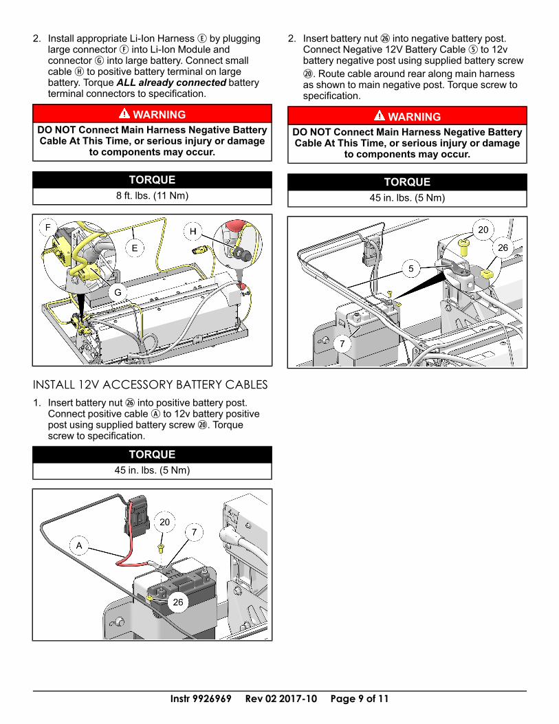
2. Install appropriate Li-Ion HarnessE by plugginglarge connectorF into Li-Ion Module andconnectorG into large battery. Connect smallcableH to positive battery terminal on largebattery. Torque ALL already connected batteryterminal connectors to specification.
WARNINGDO NOT Connect Main Harness Negative BatteryCable At This Time, or serious injury or damage
to components may occur.
TORQUE8 ft. lbs. (11 Nm)
INSTALL 12V ACCESSORY BATTERY CABLES1. Insert battery nut 2^ into positive battery post.
Connect positive cableA to 12v battery positivepost using supplied battery screw 2). Torquescrew to specification.
TORQUE45 in. lbs. (5 Nm)
2. Insert battery nut 2^ into negative battery post.Connect Negative 12V Battery Cablet to 12vbattery negative post using supplied battery screw2). Route cable around rear along main harnessas shown to main negative post. Torque screw tospecification.
WARNINGDO NOT Connect Main Harness Negative BatteryCable At This Time, or serious injury or damage
to components may occur.
TORQUE45 in. lbs. (5 Nm)

Instr 9926969 Rev 02 2017-10 Page 10 of 11
HARNESS ROUTING1. Route harnesses and attach to vehicle using cable
tiesa and edge clipsd as shown.
2. Plug lithium harness connectorA into diagnosticport connectorB and replace diagnostic portconnectorB with other lithium harness connectorC.
NOTEIf vehicle is equipped with EPS or other CAN-Basedaccessories, see “ACCESSORIES - CAN-BASED”section of GEM Service Manual for more details on
sequence of connections.
3. Remove eight push rivetsD from upper dashpanelE. Slowly lift upper dash and disconnectswitchF.
4. Route rest of harness through front plastic splashguardG. Install terminal harnessH to accessoryblockJ. Install harness connectorK.
5. Install relayL in fuse boxM as shown.
6. Reinstall upper dash panelE with retained push-pin rivetsD. Make sure to connect all switchesF.

Instr 9926969 Rev 02 2017-10 Page 11 of 11
7. Connect main harnessN and 12v battery harnesst Negative cables to negative battery postP.Torque fastener to specification.
TORQUE8 ft. lbs. (11 Nm)
8. Reconnect main vehicle disconnect. Reinstallbattery cover and reinstall hood with thumbscrews.
FEEDBACK FORMA feedback form has been created for the installer to provide any comments, questionsor concerns about the installation instructions. The form is viewable on mobile devicesby scanning the QR code or by clicking HERE if viewing on a PC.
FEEDBACK FORM


