LHC Upgrade (accelerator) - ::: The Center for High Energy...
40
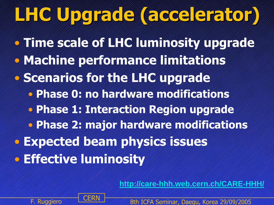
8th ICFA Seminar, Daegu, Korea 29/09/2005 CERN F. Ruggiero http://care-hhh.web.cern.ch/CARE-HHH/ LHC Upgrade (accelerator) LHC Upgrade (accelerator) • Time scale of LHC luminosity upgrade • Machine performance limitations • Scenarios for the LHC upgrade • Phase 0: no hardware modifications • Phase 1: Interaction Region upgrade • Phase 2: major hardware modifications • Expected beam physics issues • Effective luminosity
Transcript of LHC Upgrade (accelerator) - ::: The Center for High Energy...
8th ICFA Seminar, Daegu, Korea 29/09/2005CERNF. Ruggiero
http://care-hhh.web.cern.ch/CARE-HHH/
LHC Upgrade (accelerator)LHC Upgrade (accelerator)• Time scale of LHC luminosity upgrade• Machine performance limitations• Scenarios for the LHC upgrade
• Phase 0: no hardware modifications• Phase 1: Interaction Region upgrade• Phase 2: major hardware modifications
• Expected beam physics issues • Effective luminosity
F. Ruggiero LHC upgrade scenariosCERN
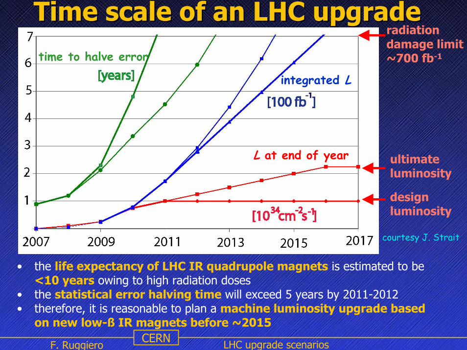
Time scale of an LHC upgradeTime scale of an LHC upgrade
L at end of year
time to halve error
integrated L
radiationdamage limit~700 fb-1
• the life expectancy of LHC IR quadrupole magnets is estimated to be <10 years owing to high radiation doses
• the statistical error halving time will exceed 5 years by 2011-2012• therefore, it is reasonable to plan a machine luminosity upgrade based
on new low-ß IR magnets before ~2015
design luminosity
ultimate luminosity
courtesy J. Strait

F. Ruggiero LHC upgrade scenariosCERN
Chronology of LHC Upgrade studiesChronology of LHC Upgrade studies• Summer 2001: two CERN task forces investigate physics potential
(CERN-TH-2002-078) and accelerator aspects (LHC Project Report 626)of an LHC upgrade by a factor 10 in luminosity and 2-3 in energy
• March 2002: LHC IR Upgrade collaboration meeting http://cern.ch/lhc-proj-IR-upgrade
• October 2002: ICFA Seminar at CERN on“Future Perspectives in High Energy Physics”
• 2003: US LHC Accelerator Research Program (LARP)
• 2004: CARE-HHH European Network on High EnergyHigh Intensity
Hadron Beams• November 2004: first CARE-HHH-APD Workshop (HHH-04) on
“Beam Dynamics in Future Hadron Colliders and Rapidly Cycling High-Intensity Synchrotrons”, CERN-2005-006
• September 2005: CARE-HHH Workshop (LHC-LUMI-05) on“Scenarios for the LHC Luminosity Upgrade”http://care-hhh.web.cern.ch/CARE-HHH/LUMI-05/

F. Ruggiero LHC upgrade scenariosCERN
Nominal LHC parametersNominal LHC parameterscollision energydipole peak fieldinjection energy
Ecm
BEinj
2x7 8.3
450
TeVT
GeV
1011
nsA
MJkW
μmcm
μmm
μrad
hcm-2s-1
fb-1/year
protons per bunchbunch spacingaverage beam current
Nb
∆tI
1.1525
0.58
stored energy per beamradiated power per beam
3623.7
εn
σz
σ*β*θc
τL
L
∫ L dt
normalized emittancerms bunch length
3.757.55
beam size at IP1&IP5beta function at IP1&IP5full crossing angle
16.60.55
285
luminosity lifetimepeak luminosityevents per bunch crossing
15.5
1034
19.2
integrated luminosity 66.2
F. Ruggiero LHC upgrade scenariosCERN
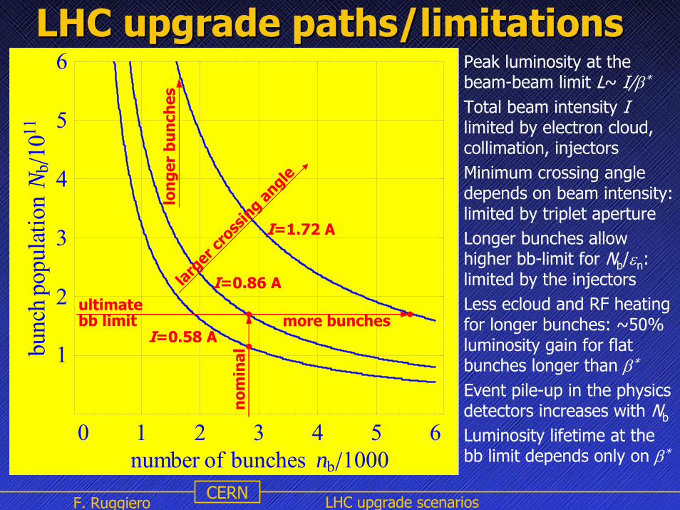
• Peak luminosity at the beam-beam limit L~ I/β*
• Total beam intensity Ilimited by electron cloud, collimation, injectors
• Minimum crossing angle depends on beam intensity: limited by triplet aperture
• Longer bunches allow higher bb-limit for Nb/εn: limited by the injectors
• Less ecloud and RF heating for longer bunches: ~50% luminosity gain for flat bunches longer than β*
• Event pile-up in the physics detectors increases with Nb
• Luminosity lifetime at the bb limit depends only on β*
0 1 2 3 4 5 6number of bunches nb 1000
1
2
3
4
5
6hcnub
noitalupopN b
ê0111
LHC upgrade paths/limitationsLHC upgrade paths/limitations
I=0.86 A
I=1.72 An
omin
al
ultimate
I=0.58 A
larg
er cr
ossin
g angle
lon
ger
bun
ches
bb limit more bunches

F. Ruggiero LHC upgrade scenariosCERN
The peak LHC luminosity can be multiplied by:
factor 2.3 from nominal to ultimate beam intensity (0.58 ⇒ 0.86 A)factor 2 (or more?) from new low-beta insertions with ß* = 0.25 m
Tturnaround~10 h ⇒ ∫Ldt ~ 3 x nominal ~ 200/(fb*year)
Expected factors for the LHC Expected factors for the LHC luminosity upgrade luminosity upgrade
Major hardware upgrades (LHC main ring and injectors) are needed to exceed ultimate beam intensity. The peak luminosity can be increased by: factor 2 if we can double the number of bunches (maybe impossible due to electron cloud effects) or increase bunch intensity and bunch length
Tturnaround~10 h ⇒ ∫Ldt ~ 6 x nominal ~ 400/(fb*year)
Increasing the LHC injection energy to 1 TeV would potentially yield:factor ~2 in peak luminosity (2 x bunch intensity and 2 x emittance)factor 1.4 in integrated luminosity from shorter Tturnaround~5 h
thus ensuring L~1035 cm-2 s-1 and ∫Ldt ~ 9 x nominal ~ 600/(fb*year)
F. Ruggiero LHC upgrade scenariosCERN
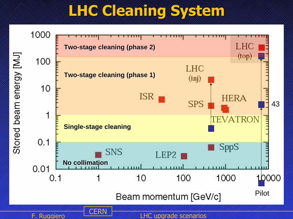
LHC Cleaning SystemLHC Cleaning System
43
Pilot
No collimationNo collimation
SingleSingle--stage cleaningstage cleaning
TwoTwo--stage cleaning (phase 1)stage cleaning (phase 1)
TwoTwo--stage cleaning (phase 2)stage cleaning (phase 2)

F. Ruggiero LHC upgrade scenariosCERN
Luminosity optimizationLuminosity optimization
Collisions with full crossing angle θc
reduce luminosity by a geometric factor F
maximum luminosity below beam-beam limit ⇒ short bunches and minimum crossing angle (baseline scheme)
H-V crossings in two IP’s ⇒ no linear tune shift due to long range
total linear bb tune shift also reduced by F
INNfnLn
b*2
2brevb
44 επβγ
πσ==
∗
∗∗ = εβσ transverse beam size at IP
peak luminosity for head-on collisionsround beams, short Gaussian bunches
I = nbfrevNb total beam current• long range beam-beam• collective instabilities• synchrotron radiation• stored beam energy
βσγγεε
2
n == normalized emittance
Nb/εn beam brightness• head-on beam-beam• space-charge in the injectors• transfer dilution
2
*211/ ⎟
⎠⎞
⎜⎝⎛+≅
σσθ zcF
FrN
Qn
pbyxbb 2πεξξ ≅+=Δ

F. Ruggiero LHC upgrade scenariosCERN
If bunch intensity and brightness are not limited by the injectors or by other effects in the LHC (e.g. electron cloud) ⇒ luminosity can be increased without exceeding beam-beam limit ΔQbb~0.01by increasing the crossing angle and/or the bunch length
Express beam-beam limited brilliance Nb/εn in terms of maximumtotal beam-beam tune shift ΔQbb, then
2
*zc
*nb
2bb
2p
rev*bb
p 21
2⎟⎠⎞
⎜⎝⎛+
Δ≅
Δ≅
σσθ
βεγπ
βγ nQ
rfIQ
rL
At high beam intensities or for large emittances, the performancewill be limited by the angular triplet aperture
⎪⎭
⎪⎬⎫
⎪⎩
⎪⎨⎧
⎟⎟⎠
⎞⎜⎜⎝
⎛
+Δ≅
2
θc
*
*bbp /20
/1,1min2 σθεβγ ltriplA
IQr
L
F. Ruggiero LHC upgrade scenariosCERN
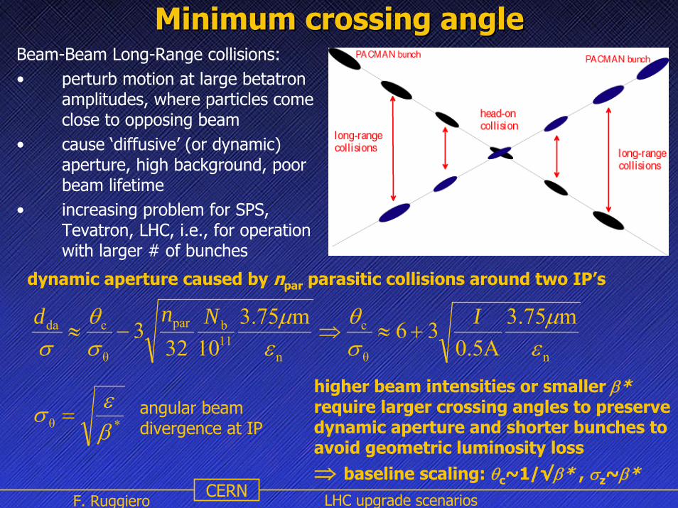
Minimum crossing angleMinimum crossing angleBeam-Beam Long-Range collisions:• perturb motion at large betatron
amplitudes, where particles come close to opposing beam
• cause ‘diffusive’ (or dynamic) aperture, high background, poor beam lifetime
• increasing problem for SPS, Tevatron, LHC, i.e., for operation with larger # of bunches
higher beam intensities or smaller β*require larger crossing angles to preserve dynamic aperture and shorter bunches to avoid geometric luminosity loss ⇒ baseline scaling: θc~1/√β* , σz~β*
nθ
c
n11bpar
θ
cda m75.3A5.0
36m75.31032
3εμ
σθ
εμ
σθ
σINnd
+≈⇒−≈
dynamic aperture caused by npar parasitic collisions around two IP’s
*θ βεσ = angular beam
divergence at IP

2nd prototype BBLR in the CERN SPShas demonstrated benefit of compensation
G. Burtin, J. Camas, J.-P. Koutchouk, et al.
F. Ruggiero LHC upgrade scenariosCERN
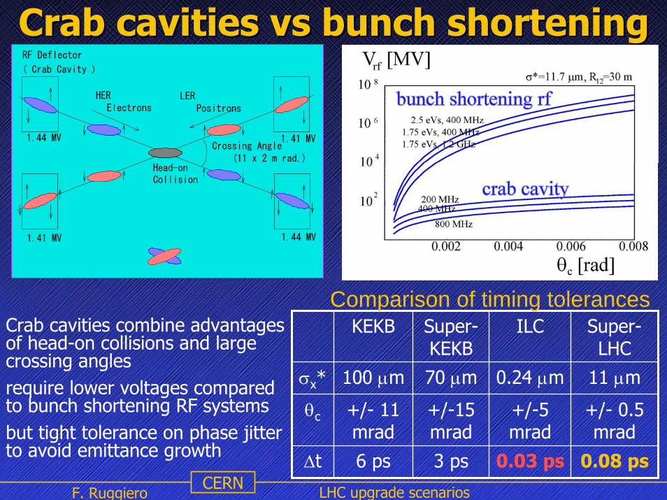
Crab cavities vs bunch shorteningCrab cavities vs bunch shortening
Crab cavities combine advantages of head-on collisions and large crossing anglesrequire lower voltages compared to bunch shortening RF systemsbut tight tolerance on phase jitter to avoid emittance growth
KEKB Super-KEKB
ILC Super-LHC
σx* 100 μm 70 μm 0.24 μm 11 μm
θc +/- 11 mrad
+/-15 mrad
+/-5 mrad
+/- 0.5 mrad
Δt 6 ps 3 ps 0.03 ps 0.08 ps
Comparison of timing tolerances
RF Deflector
( Crab Cavity )
Head-onCollision
Crossing Angle (11 x 2 m rad.)
Electrons PositronsLERHER
1.41 MV
1.41 MV
1.44 MV
1.44 MV

CERN
Electron Cloud Effects
��������
��������
������������������������������������������������������������������������������������������������������������������������������������������������������������������������������������������
������������������������������������������������������������������������������������������������������������������������������������������������������������������������������������������
�����������������������������������������������������������������������������������������������������������������������������������������������������������
�����������������������������������������������������������������������������������������������������������������������������������������������������������
�����������������������������������������������������������������������������������������������������������������������������������������������������������
�����������������������������������������������������������������������������������������������������������������������������������������������������������
��������
5 ns
γ γ γ
20 ns5 ns20 ns
phot
oele
ctro
n
secondary electron
10 eV10 eV 10 eV
2 ke
V
200
eV
200
eV
200
eV
2 ke
V5 eV
secondary electron5 eV
5 eV
LOST or REFLECTED
time
In the LHC, photoelectrons created at the vacuum pipe wall are
accelerated by proton bunches up to 200 eV and cross the pipe in about
5 ns. Slow or reflected secondary electrons survive until the next bunch.
Depending on vacuum pipe surface conditions (SEY) and bunch spacing,
this may lead to an electron cloud build-up with implications for beam
stability, emittance growth, and heat load on the cold LHC beam screen.
F. Ruggiero LHC upgrade scenarios

12
blue: e-cloud effect observedred: planned accelerators
longer fewer more intense bunches
more ‘ultimate’bunches
Scaling of electron cloud effects
experienceat severalstorage ringssuggests thatthe e-cloudthreshold scales as Nb~Δtsep
possible LHCupgrades considereithersmaller Δtsepwith constantNb, or theyincrease Δtsepin proportionto Nb

F. Ruggiero LHC upgrade scenariosCERN
Schematic of reduced electron cloud build up for a longbunch. Most electrons do not gain any energy when traversing the chamber in the quasi-static beam potential
[after V. Danilov]negligible heat load
F. Ruggiero LHC upgrade scenariosCERN
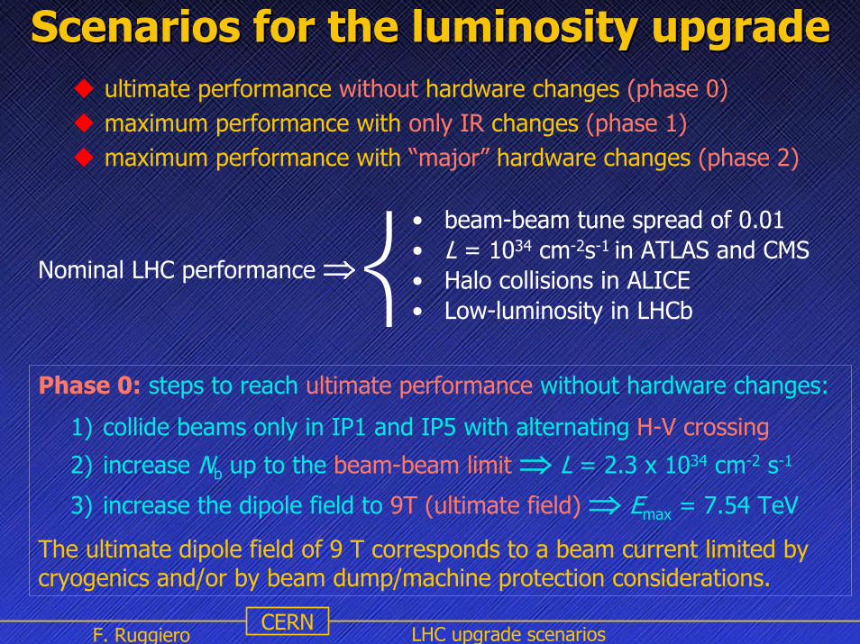
Scenarios for the luminosity upgradeScenarios for the luminosity upgradeultimate performance without hardware changes (phase 0)maximum performance with only IR changes (phase 1)maximum performance with “major” hardware changes (phase 2)
Phase 0: steps to reach ultimate performance without hardware changes:
1) collide beams only in IP1 and IP5 with alternating H-V crossing
2) increase Nb up to the beam-beam limit ⇒ L = 2.3 x 1034 cm-2 s-1
3) increase the dipole field to 9T (ultimate field) ⇒ Emax = 7.54 TeV
The ultimate dipole field of 9 T corresponds to a beam current limited bycryogenics and/or by beam dump/machine protection considerations.
⎨• beam-beam tune spread of 0.01• L = 1034 cm-2s-1 in ATLAS and CMS• Halo collisions in ALICE• Low-luminosity in LHCb
Nominal LHC performance ⇒
F. Ruggiero LHC upgrade scenariosCERN
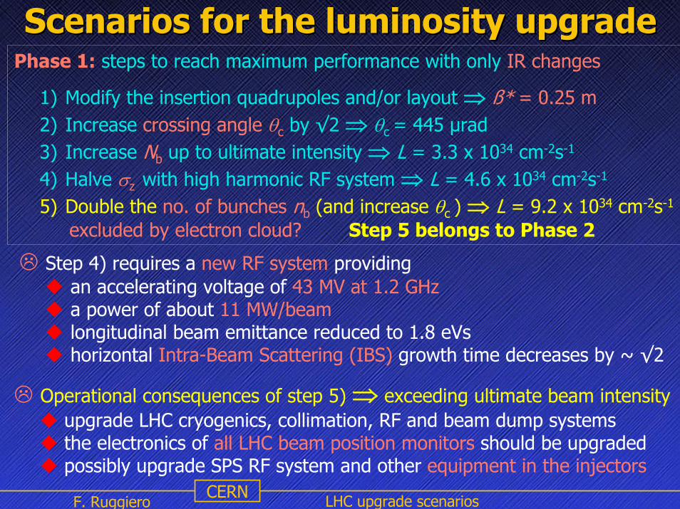
Phase 1: steps to reach maximum performance with only IR changes
1) Modify the insertion quadrupoles and/or layout ⇒ ß* = 0.25 m2) Increase crossing angle θc by √2 ⇒ θc = 445 µrad3) Increase Nb up to ultimate intensity ⇒ L = 3.3 x 1034 cm-2s-1
4) Halve σz with high harmonic RF system ⇒ L = 4.6 x 1034 cm-2s-1
5) Double the no. of bunches nb (and increase θc ) ⇒ L = 9.2 x 1034 cm-2s-1
excluded by electron cloud? Step 5 belongs to Phase 2
Step 4) requires a new RF system providing an accelerating voltage of 43 MV at 1.2 GHza power of about 11 MW/beamlongitudinal beam emittance reduced to 1.8 eVshorizontal Intra-Beam Scattering (IBS) growth time decreases by ~ √2
Operational consequences of step 5) ⇒ exceeding ultimate beam intensityupgrade LHC cryogenics, collimation, RF and beam dump systemsthe electronics of all LHC beam position monitors should be upgradedpossibly upgrade SPS RF system and other equipment in the injectors
Scenarios for the luminosity upgradeScenarios for the luminosity upgrade

F. Ruggiero LHC upgrade scenariosCERN
Various LHC upgrade options Various LHC upgrade options parameter symbol nominal ultimate shorter
bunchlonger bunch
no of bunches nb 2808 2808 5616 936
proton per bunch Nb [1011] 1.15 1.7 1.7 6.0
bunch spacing ∆tsep [ns] 25 25 12.5 75
average current I [A] 0.58 0.86 1.72 1.0
normalized emittance εn [µm] 3.75 3.75 3.75 3.75
longit. profile Gaussian Gaussian Gaussian flat
rms bunch length σz [cm] 7.55 7.55 3.78 14.4
ß* at IP1&IP5 ß* [m] 0.55 0.50 0.25 0.25
full crossing angle θc [µrad] 285 315 445 430
Piwinski parameter θc σz/(2σ*) 0.64 0.75 0.75 2.8
peak luminosity L [1034 cm-2 s-1] 1.0 2.3 9.2 8.9
events per crossing 19 44 88 510
luminous region length σlum [mm] 44.9 42.8 21.8 36.2

F. Ruggiero LHC upgrade scenariosCERN
Interaction Region upgradeInteraction Region upgrade
factors driving IR design:• minimize β*• minimize effect of LR collisions• large radiation power directed towards the IRs• accommodate crab cavities and/or beam-beam
compensators. Local Q’ compensation scheme?• compatibility with upgrade path
goal: reduce β* by at least a factor 2
maximize magnet aperture,minimize distance to IR
options: NbTi ‘cheap’ upgrade, NbTi(Ta), Nb3Snnew quadrupoles new separation dipoles
F. Ruggiero LHC upgrade scenariosCERN
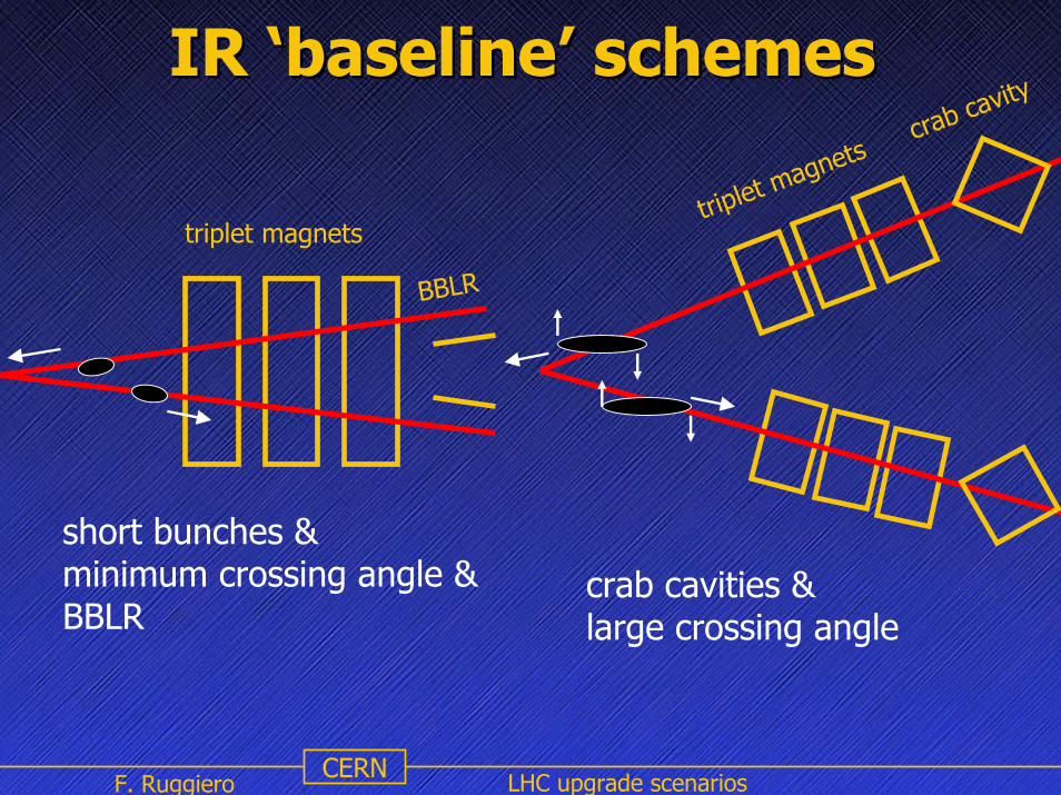
IR IR ‘‘baselinebaseline’’ schemesschemes
short bunches & minimum crossing angle &BBLR
crab cavities & large crossing angle
triplet magnetstriplet magnets
crab cavity
BBLR

F. Ruggiero LHC upgrade scenariosCERN
alternative IR schemesalternative IR schemes
dipole first & small crossing angle
triplet magnetsdipole magnets
dipole first & large crossing angle &long bunches or crab cavities
triplet magnetsdipole
reduced # LR collisionscollision debris hit D1
F. Ruggiero LHC upgrade scenariosCERN
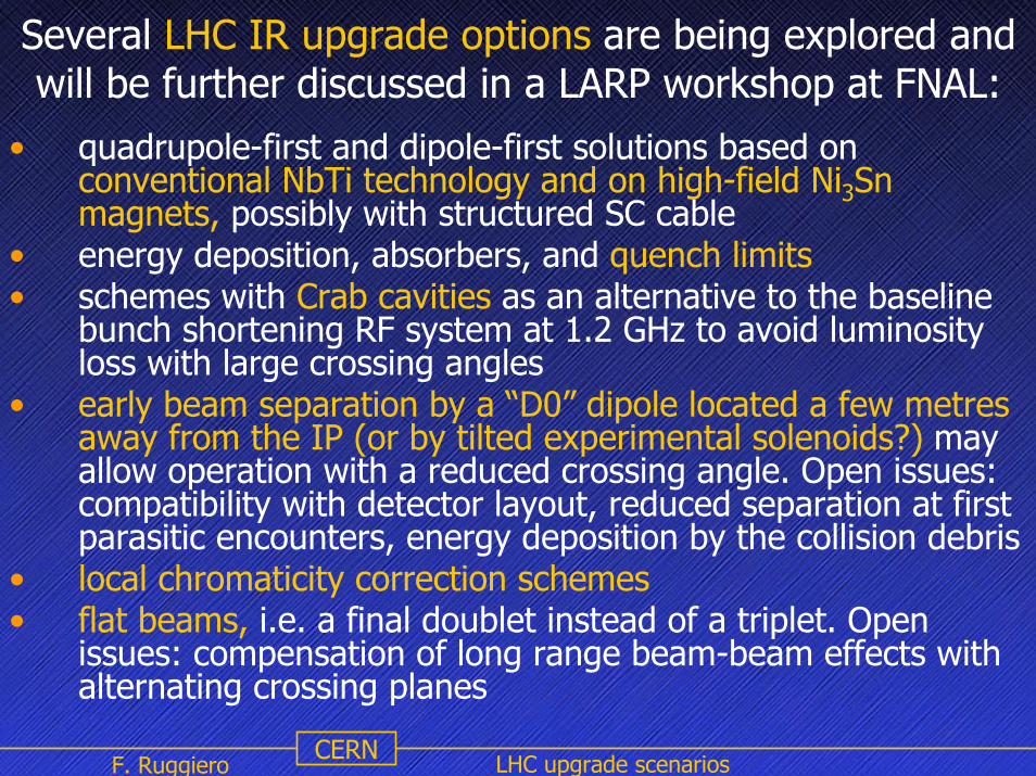
• quadrupole-first and dipole-first solutions based on conventional NbTi technology and on high-field Ni3Sn magnets, possibly with structured SC cable
• energy deposition, absorbers, and quench limits• schemes with Crab cavities as an alternative to the baseline
bunch shortening RF system at 1.2 GHz to avoid luminosity loss with large crossing angles
• early beam separation by a “D0” dipole located a few metres away from the IP (or by tilted experimental solenoids?) may allow operation with a reduced crossing angle. Open issues: compatibility with detector layout, reduced separation at first parasitic encounters, energy deposition by the collision debris
• local chromaticity correction schemes• flat beams, i.e. a final doublet instead of a triplet. Open
issues: compensation of long range beam-beam effects with alternating crossing planes
Several LHC IR upgrade options are being explored and will be further discussed in a LARP workshop at FNAL:

F. Ruggiero LHC upgrade scenariosCERN
Tentative milestones for Tentative milestones for future machine studiesfuture machine studies
• 2006: installation and test of a beam-beam long range compensation system at RHIC to be validated with colliding beams
• 2006/2007: new SPS experiment for crystal collimation,complementary to Tevatron results
• 2006: installation and test of Crab cavities at KEKB to validate higher beam-beam limit and luminosity with large crossing angles
• 2007: if KEKB test successful, test of Crab cavities in a hadron machine (RHIC?) to validate low RF noise and emittance preservation

F. Ruggiero LHC upgrade scenariosCERN
Injector chain for 1 TeV proton beamsinjecting at 1 TeV into the LHC reduces dynamic effects of persistent currents, i.e.:
persistent current decay during the injection flat bottomsnap-back at the beginning of the acceleration ⇒ easier beam control
⇒ decreases turn-around time and hence increases integrated luminosity
L0
[cm-2s-1]τL
[h]Tturnaround
[h]Trun
[h]∫200 days L dt[fb-1] gain
1034 15 10 14.6 66 x1.0
1034 15 5 10.8 85 x1.3
1035 6.1 10 8.5 434 x6.6
1035 6.1 5 6.5 608 x9.2
⎪⎪⎩
⎪⎪⎨
⎧
+++
×=
=+
+⇒
∫run
L
run
0 Lturnaroundrun
turnaroundrun
L
0
L
turnaroundrun
run
1 (optimum) T
T
TTTTLLdt
eTT
T
ττ
ττ
with τgas = 85 h andτx
IBS= 106 h (nom) ⇒ 40 h (high-L)
F. Ruggiero LHC upgrade scenariosCERN
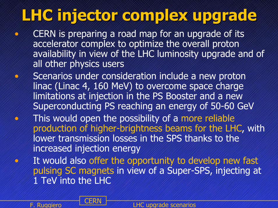
LHC injector complex upgradeLHC injector complex upgrade• CERN is preparing a road map for an upgrade of its
accelerator complex to optimize the overall proton availability in view of the LHC luminosity upgrade and of all other physics users
• Scenarios under consideration include a new proton linac (Linac 4, 160 MeV) to overcome space charge limitations at injection in the PS Booster and a new Superconducting PS reaching an energy of 50-60 GeV
• This would open the possibility of a more reliable production of higher-brightness beams for the LHC, with lower transmission losses in the SPS thanks to the increased injection energy
• It would also offer the opportunity to develop new fast pulsing SC magnets in view of a Super-SPS, injecting at 1 TeV into the LHC

F. Ruggiero LHC upgrade scenariosCERN
Additional Slides

16
luminosity upgrade: baseline scheme
increase Nb
bblimit?
restore F2/12
*zc
21
−
⎟⎟
⎠
⎞
⎜⎜
⎝
⎛⎟⎟⎠
⎞⎜⎜⎝
⎛+≈
σσθF
no
yes
θc>θmindue to LR-bb
crab cavities
BBLRcompen-sation
reduce σzby factor ~2using higherfrf & lower ε||(larger θc ?)
2.3
reduce θc(squeeze β*)
use large θc& pass each beamthrough separatemagnetic channel
reduce β* byfactor ~2
new IRmagnets
increase nb byfactor ~2
if e-cloud, dump &impedance ok
9.2
1.0
4.6
simplified IR design with large θc
peak luminosity gain1.72 A
0.86 A
0.86 A
beam current
0.58 A
or decouple L and F

17
luminosity upgrade: Piwinski scheme
reduce β* byfactor ~2
new IRmagnets
decrease F2/12
*zc
21
−
⎟⎟
⎠
⎞
⎜⎜
⎝
⎛⎟⎟⎠
⎞⎜⎜⎝
⎛+≈
σσθF
increase σzθc
increase Nb
nobb
p
nb
2 QFr
N Δ=πε
?
yes
reduce #bunchesto limit total current?
flatten profile?
7.7 15.5
1.0
0.86 A
superbunches?
1.72 A
luminosity gain
beam current
0.58 A

10
yx
pbHO
rN
,4πγεξ ≡
22d
n HOparLR
ξξ =
ξΗΟ / IP no. of IPs ΔQbb totalSPS 0.005 3 0.015Tevatron (pbar) 0.01-0.02 2 0.02-0.04RHIC 0.002 4 ~0.008LHC (nominal) 0.0034 2 (4) ~0.01
tune shift from head-on collision (primary IPs)
tune shift from long-range collisions
conservative value for total tune spread based on SPScollider experience
beam-beam: tune shift
increases withreduced bunch spacingor crossing angle
limit on ξΗΟlimits Nb/(γε)
d: normalized separation, cd θ∝

F. Ruggiero LHC upgrade scenariosCERN
� � � � � � � � � � � � � �
� � � � � � � � � � � � � � � � �
� � � � � � � � � � � � � � � � �
� � � � � � � � � � � � � � � �
Schematic of a super-bunch collision, consisting of ‘head-on’and ‘long-range’ components. The luminosity for long bunches having flat longitudinal distribution is ~1.4 times higher than for conventional Gaussian bunches with the same beam-beam tune shift and identical bunch population (see LHC Project Report 627)
Frank Zimmermann, LTC 06.04.05
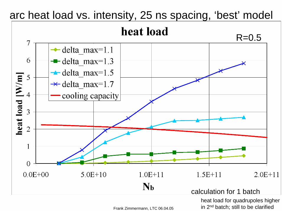
arc heat load vs. intensity, 25 ns spacing, ‘best’ model
calculation for 1 batch
R=0.5
heat load for quadrupoles higherin 2nd batch; still to be clarified

arc heat load vs. spacing, Nb=1.15x10¹¹, ‘best’ model
cooling capacity
R=0.5
Frank Zimmermann, LTC 06.04.05

F. Ruggiero LHC upgrade scenariosCERN
Events per bunch crossing and beam Events per bunch crossing and beam lifetime due to nuclear plifetime due to nuclear p--p collisionsp collisions
rev
bb
bing-Xevents
fnL σ
= σbb=60 mb total inelastic cross section
TOT
bbN 2
/σ
τ LNn=
beam intensity halving time due to nuclear p-p collisions at two IP’s with total cross section σTOT=110 mb
NgasxIBS
L 54.122
11
τττ
τ++
= luminosity lifetime: assumes radiation damping compensates diffusion
54.1)1( N
Nττ ≅−eexponential luminosity lifetime
due to nuclear p-p interactions
*bb
p
rev
bb 2 βγ Q
rf
NnL Δ
≅ nuclear scattering lifetime at the beam-beam limit depends only on β* !
F. Ruggiero LHC upgrade scenariosCERN
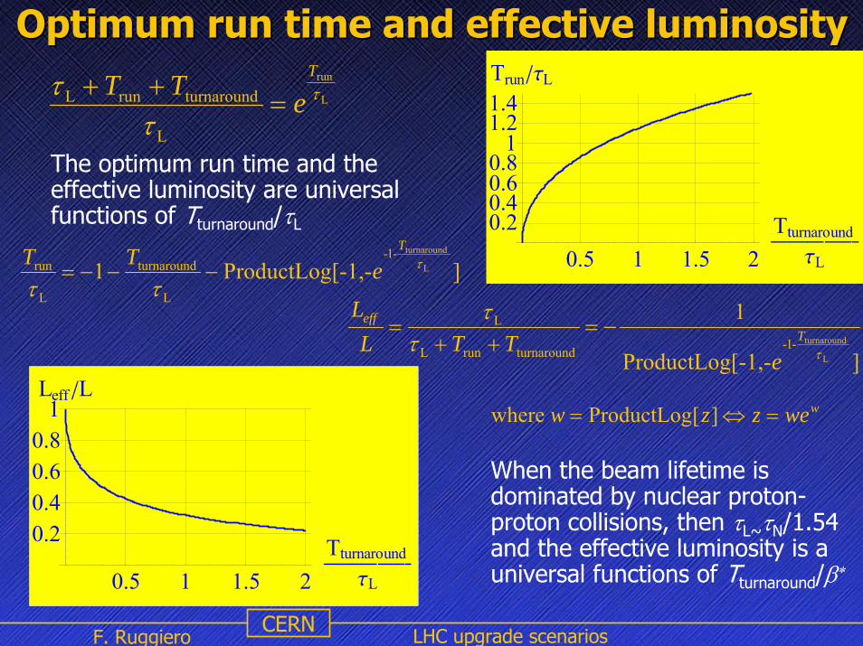
Optimum run time and effective luminosityOptimum run time and effective luminosity
L
run
L
turnaroundrunL τ
ττ T
eTT=
++
][-1,-ProductLog1 L
turnaround-1-
L
turnaround
L
run τ
ττ
T
eTT−−−=
The optimum run time and the effective luminosity are universal functions of Tturnaround/τL
wwezzw =⇔= ][ProductLog where
][-1,-ProductLog
1
L
turnaround-1-turnaroundrunL
L
τττ
Teff
eTTL
L−=
++=
When the beam lifetime is dominated by nuclear proton-proton collisions, then τL~τN/1.54 and the effective luminosity is a universal functions of Tturnaround/β∗
0.5 1 1.5 2TturnaroundÅÅÅÅÅÅÅÅÅÅÅÅÅÅÅÅ ÅÅÅÅÅÅÅÅÅÅ
tL
0.20.40.60.8
11.21.4TrunêtL
0.5 1 1.5 2TturnaroundÅÅÅÅÅÅÅÅÅÅÅÅÅÅÅÅ ÅÅÅÅÅÅÅÅÅÅ
tL
0.20.40.60.8
1Leff êL

F. Ruggiero LHC upgrade scenariosCERN
Effective luminosity for various upgrade options Effective luminosity for various upgrade options parameter symbol nominal ultimate shorter
bunchlonger bunch
protons per bunch Nb [1011] 1.15 1.7 1.7 6.0
bunch spacing ∆tsep [ns] 25 25 12.5 75
average current I [A] 0.58 0.86 1.72 1.0
longitudinal profile Gaussian Gaussian Gaussian flat
rms bunch length σz [cm] 7.55 7.55 3.78 14.4
ß* at IP1&IP5 ß* [m] 0.55 0.50 0.25 0.25
full crossing angle θc [µrad] 285 315 445 430
Piwinski parameter θc σz/(2σ*) 0.64 0.75 0.75 2.8
peak luminosity L [1034 cm-2 s-1] 1.0 2.3 9.2 8.9
events per crossing 19 44 88 510
IBS growth time τxIBS [h] 106 72 42 75
nuclear scatt. lumi lifetime τN/1.54 [h] 26.5 17 8.5 5.2
(Tturnaround=10 h) Trun [h] optimum 14.6 12.3 8.9 7.0
effective luminosity Leff [1034 cm-2 s-1] 0.5 1.0 3.3 2.7
(Tturnaround= 5 h) Trun [h] optimum 10.8 9.1 6.7 5.4
luminosity lifetime (τgas =85 h) τL [h] 15.5 11.2 6.5 4.5
effective luminosity Leff [1034 cm-2 s-1] 0.4 0.8 2.4 1.9

F. Ruggiero LHC upgrade scenariosCERN
CERN: the WorldCERN: the World’’s Most Complete s Most Complete Accelerator Complex (not to scale)Accelerator Complex (not to scale)
F. Ruggiero LHC upgrade scenariosCERN
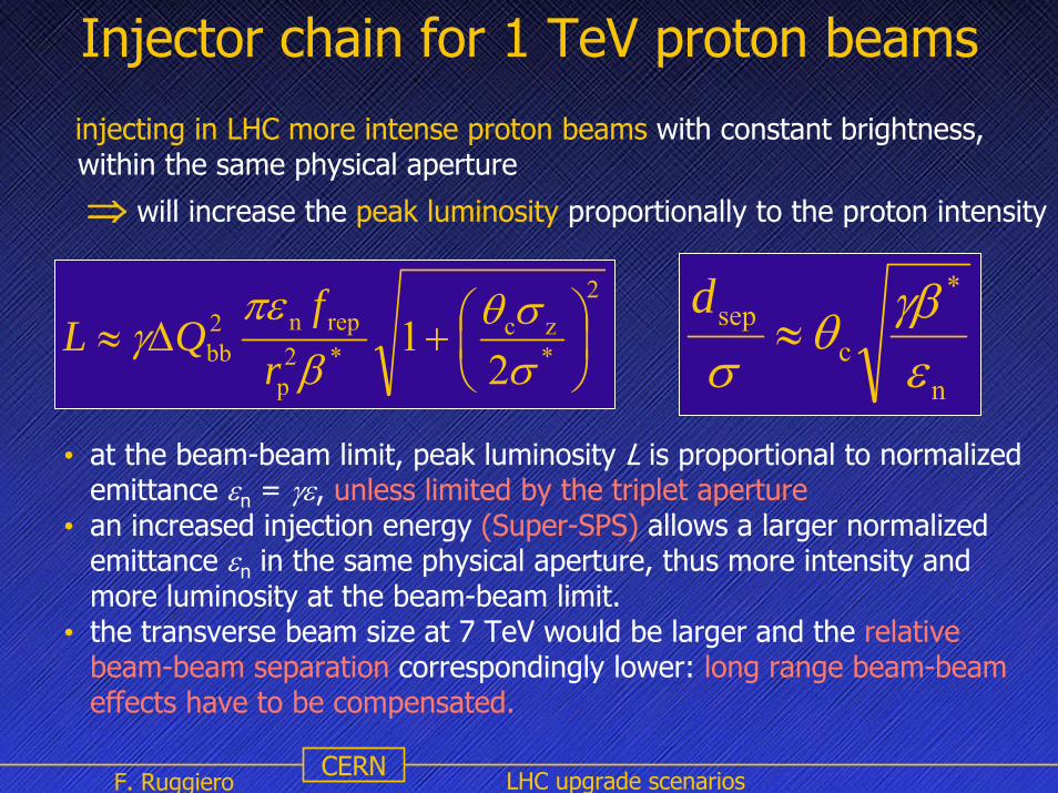
Injector chain for 1 TeV proton beams
injecting in LHC more intense proton beams with constant brightness, within the same physical aperture
⇒ will increase the peak luminosity proportionally to the proton intensity
• at the beam-beam limit, peak luminosity L is proportional to normalized emittance εn = γε, unless limited by the triplet aperture
• an increased injection energy (Super-SPS) allows a larger normalized emittance εn in the same physical aperture, thus more intensity and more luminosity at the beam-beam limit.
• the transverse beam size at 7 TeV would be larger and the relative beam-beam separation correspondingly lower: long range beam-beam effects have to be compensated.
2
*zc
*2p
repn2bb 2
1 ⎟⎠⎞
⎜⎝⎛+Δ≈
σσθ
βπε
γr
fQL
n
*
csep
εγβθ
σ≈
d

F. Ruggiero LHC upgrade scenariosCERN
‘‘cheapcheap’’ IR upgradeIR upgrade
short bunches & minimum crossing angle &BBLR
triplet magnets
each quadrupole individually optimized (length & aperture) reduced IP-quad distance from 23 to 22 mconventional NbTi technology: β*=0.25 m is possible
BBLR
in case we need to double LHC luminosity earlier than foreseen

• active beam-beam compensation programme in progress for Tevatron & LHC
• TEL promising, but conditions difficult to control
• wire compensation of LR collisions at LHC will allow smaller crossing angles and/or higher bunchcharges;
experimental demonstration in the SPS;
pulsed wire desirable for selective correction of PACMAN bunches
•crab cavities alternative option for large crossing angle
Summary Beam-Beam Compensation
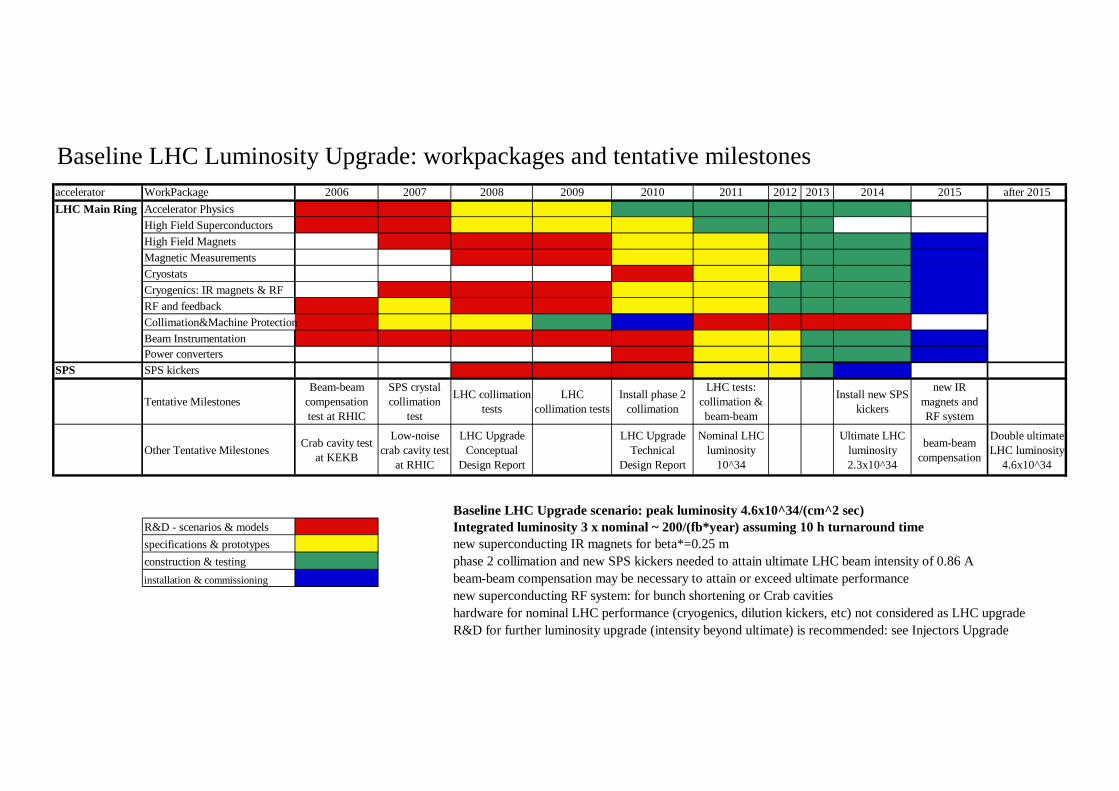
Baseline LHC Luminosity Upgrade: workpackages and tentative milestonesaccelerator WorkPackage 2006 2007 2008 2009 2010 2011 2012 2013 2014 2015 after 2015LHC Main Ring Accelerator Physics
High Field SuperconductorsHigh Field MagnetsMagnetic MeasurementsCryostatsCryogenics: IR magnets & RFRF and feedbackCollimation&Machine ProtectionBeam InstrumentationPower converters
SPS SPS kickers
Tentative MilestonesBeam-beam
compensation test at RHIC
SPS crystal collimation
test
LHC collimation tests
LHC collimation tests
Install phase 2 collimation
LHC tests: collimation & beam-beam
Install new SPS kickers
new IR magnets and RF system
Other Tentative Milestones Crab cavity test at KEKB
Low-noise crab cavity test
at RHIC
LHC Upgrade Conceptual
Design Report
LHC Upgrade Technical
Design Report
Nominal LHC luminosity
10^34
Ultimate LHC luminosity 2.3x10^34
beam-beam compensation
Double ultimate LHC luminosity
4.6x10^34
Baseline LHC Upgrade scenario: peak luminosity 4.6x10^34/(cm^2 sec)R&D - scenarios & models Integrated luminosity 3 x nominal ~ 200/(fb*year) assuming 10 h turnaround timespecifications & prototypes new superconducting IR magnets for beta*=0.25 mconstruction & testing phase 2 collimation and new SPS kickers needed to attain ultimate LHC beam intensity of 0.86 Ainstallation & commissioning beam-beam compensation may be necessary to attain or exceed ultimate performance
new superconducting RF system: for bunch shortening or Crab cavitieshardware for nominal LHC performance (cryogenics, dilution kickers, etc) not considered as LHC upgradeR&D for further luminosity upgrade (intensity beyond ultimate) is recommended: see Injectors Upgrade