LGA1150 Socket — Application Guide · PDF file2 LGA1150 Socket Land Pattern ... Desktop...
36
LGA1150 Socket Application Guide September 2013 Order No.: 328999-002
Transcript of LGA1150 Socket — Application Guide · PDF file2 LGA1150 Socket Land Pattern ... Desktop...

LGA1150 SocketApplication Guide
September 2013
Order No.: 328999-002

INFORMATION IN THIS DOCUMENT IS PROVIDED IN CONNECTION WITH INTEL PRODUCTS. NO LICENSE, EXPRESS OR IMPLIED, BY ESTOPPEL OROTHERWISE, TO ANY INTELLECTUAL PROPERTY RIGHTS IS GRANTED BY THIS DOCUMENT. EXCEPT AS PROVIDED IN INTEL'S TERMS ANDCONDITIONS OF SALE FOR SUCH PRODUCTS, INTEL ASSUMES NO LIABILITY WHATSOEVER AND INTEL DISCLAIMS ANY EXPRESS OR IMPLIEDWARRANTY, RELATING TO SALE AND/OR USE OF INTEL PRODUCTS INCLUDING LIABILITY OR WARRANTIES RELATING TO FITNESS FOR APARTICULAR PURPOSE, MERCHANTABILITY, OR INFRINGEMENT OF ANY PATENT, COPYRIGHT OR OTHER INTELLECTUAL PROPERTY RIGHT.
A "Mission Critical Application" is any application in which failure of the Intel Product could result, directly or indirectly, in personal injury or death.SHOULD YOU PURCHASE OR USE INTEL'S PRODUCTS FOR ANY SUCH MISSION CRITICAL APPLICATION, YOU SHALL INDEMNIFY AND HOLD INTEL ANDITS SUBSIDIARIES, SUBCONTRACTORS AND AFFILIATES, AND THE DIRECTORS, OFFICERS, AND EMPLOYEES OF EACH, HARMLESS AGAINST ALLCLAIMS COSTS, DAMAGES, AND EXPENSES AND REASONABLE ATTORNEYS' FEES ARISING OUT OF, DIRECTLY OR INDIRECTLY, ANY CLAIM OFPRODUCT LIABILITY, PERSONAL INJURY, OR DEATH ARISING IN ANY WAY OUT OF SUCH MISSION CRITICAL APPLICATION, WHETHER OR NOT INTELOR ITS SUBCONTRACTOR WAS NEGLIGENT IN THE DESIGN, MANUFACTURE, OR WARNING OF THE INTEL PRODUCT OR ANY OF ITS PARTS.
Intel may make changes to specifications and product descriptions at any time, without notice. Designers must not rely on the absence orcharacteristics of any features or instructions marked "reserved" or "undefined". Intel reserves these for future definition and shall have noresponsibility whatsoever for conflicts or incompatibilities arising from future changes to them. The information here is subject to change withoutnotice. Do not finalize a design with this information.
The products described in this document may contain design defects or errors known as errata which may cause the product to deviate from publishedspecifications. Current characterized errata are available on request.
Contact your local Intel sales office or your distributor to obtain the latest specifications and before placing your product order.
Copies of documents which have an order number and are referenced in this document, or other Intel literature, may be obtained by calling1-800-548-4725, or go to: http://www.intel.com/design/literature.htm
This document contains information on products in the design phase of development.
Code Names are only for use by Intel to identify products, platforms, programs, services, etc. ("products") in development by Intel that have not beenmade commercially available to the public, i.e., announced, launched or shipped. They are never to be used as "commercial" names for products. Also,they are not intended to function as trademarks.
Intel, Intel Core, Pentium, Xeon, and the Intel logo, are trademarks of Intel Corporation in the U.S. and/or other countries.
*Other names and brands may be claimed as the property of others.
Copyright © 2013, Intel Corporation. All rights reserved.
LGA1150 SocketApplication Guide September 20132 Order No.: 328999-002
Contents
Revision History..................................................................................................................6
1.0 Introduction................................................................................................................. 71.1 Related Documents.................................................................................................71.2 Definition of Terms................................................................................................. 7
2.0 LGA1150 Socket...........................................................................................................92.1 Board Layout......................................................................................................... 92.2 Attachment to Motherboard....................................................................................102.3 Socket Components.............................................................................................. 112.4 Package Installation / Removal............................................................................... 132.5 Durability.............................................................................................................142.6 Markings............................................................................................................. 142.7 Component Insertion Forces...................................................................................152.8 Socket Size..........................................................................................................15
3.0 Independent Loading Mechanism (ILM)......................................................................163.1 Design Concept.................................................................................................... 163.2 Assembly of Independent Loading Mechanism (ILM) to a Motherboard......................... 193.3 Independent Loading Mechanism (ILM) Interchangeability..........................................213.4 Markings............................................................................................................. 213.5 Independent Loading Mechanism (ILM) Cover...........................................................21
4.0 LGA1150 Socket and ILM Specifications......................................................................244.1 Mechanical Specifications.......................................................................................244.2 Electrical Requirements......................................................................................... 254.3 Environmental Requirements..................................................................................26
Appendix A Component Suppliers..................................................................................... 28
Appendix B Mechanical Drawings......................................................................................29
Appendix C Heatsink Back Plate Drawings........................................................................ 34
Contents—LGA1150 Socket
LGA1150 SocketSeptember 2013 Application GuideOrder No.: 328999-002 3

Figures1 LGA1150 Pick and Place Cover.................................................................................... 92 LGA1150 Socket Land Pattern................................................................................... 103 Attachment to Motherboard...................................................................................... 114 Pick and Place Cover................................................................................................ 135 Package Installation / Removal Features.....................................................................146 ILM Assembly with Installed Processor........................................................................177 Back Plate.............................................................................................................. 188 Shoulder Screw....................................................................................................... 199 Independent Loading Mechanism (ILM) Assembly.........................................................2010 Pin1 and Independent Loading Mechanism (ILM) Lever................................................. 2011 Independent Loading Mechanism (ILM) Cover..............................................................2212 ILM Cover and PnP Cover Interference........................................................................2313 Flow Chart of Knowledge-Based Reliability Evaluation Methodology................................ 2714 Socket/Heatsink / ILM Keep-out Zone Primary Side (Top)............................................. 3015 Socket / Heatsink / ILM Keep-out Zone Secondary Side (Bottom)...................................3116 Socket / Processor / ILM Keep-out Zone Primary Side (Top).......................................... 3217 Socket / Processor / ILM Keep-out Zone Secondary Side (Bottom)................................. 3318 Heatsink Back Plate Keep-in Zone..............................................................................3519 Heatsink Back Plate................................................................................................. 36
LGA1150 Socket—Figures
LGA1150 SocketApplication Guide September 20134 Order No.: 328999-002

Tables1 Related Documents ...................................................................................................72 Terms and Descriptions..............................................................................................73 Socket Component Mass...........................................................................................244 1150-land Package and LGA1150 Socket Stackup Height.............................................. 245 Socket and ILM Mechanical Specifications .................................................................. 256 Electrical Requirements for LGA1150 Socket ...............................................................267 LGA1150 Socket and ILM Components........................................................................288 Supplier Contact Information ....................................................................................289 Mechanical Drawing List........................................................................................... 2910 Mechanical Drawing List........................................................................................... 3411 Supplier Contact Information.....................................................................................34
Tables—LGA1150 Socket
LGA1150 SocketSeptember 2013 Application GuideOrder No.: 328999-002 5

Revision History
Revision Number Description Revision Date
001 • Initial release June 2013
002 • Added Desktop Intel® Pentium processor family September 2013
LGA1150 Socket—Revision History
LGA1150 SocketApplication Guide September 20136 Order No.: 328999-002

1.0 Introduction
This document covers the LGA1150 socket for Desktop systems using the Desktop 4thGeneration Intel® Core™ processor family, Desktop Intel® Pentium® processor family,and for UP Server / Workstation systems using the Intel® Xeon® processor E3-1200v3 product family.
The information in this document include:
• The thermal and mechanical specifications for the socket
• The mechanical interface requirements to properly integrate the socket into aboard design
Related Documents
Material and concepts available in the following documents may be beneficial whenreading this document.
Table 1. Related Documents
Title Document Number /Location
Desktop 4th Generation Intel® Core™ Processor Family and Desktop Intel®Pentium® Processor Family Datasheet - Volume 1 of 2
328897
Desktop 4th Generation Intel® Core™ Processor Family and Desktop Intel®Pentium® Processor Family Datasheet - Volume 2 of 2
328898
Intel® Xeon® Processor E3-1200 v3 Product Family Datasheet - Volume 1 of 2 328907
Intel® Xeon® Processor E3-1200 v3 Product Family Datasheet - Volume 2 of 2 329000
Desktop 4th Generation Intel® Core™ Processor Family and Intel® Xeon®
Processor E3-1200 v3 Product Family Thermal Mechanical Design Guidelines328900
Intel® 8 Series / C220 Series Chipset Family Platform Controller Hub (PCH)Thermal Mechanical Specifications and Design Guidelines
328906
Definition of Terms
Table 2. Terms and Descriptions
Term Description
Bypass Bypass is the area between a passive heatsink and any object that can act to form a duct.For this example, it can be expressed as a dimension away from the outside dimension ofthe fins to the nearest surface.
CTE Coefficient of Thermal Expansion. The relative rate a material expands during a thermalevent.
DTS Digital Thermal Sensor reports a relative die temperature as an offset from TCC activationtemperature.
continued...
1.1
1.2
Introduction—LGA1150 Socket
LGA1150 SocketSeptember 2013 Application GuideOrder No.: 328999-002 7

Term Description
FSC Fan Speed Control
IHS Integrated Heat Spreader: a component of the processor package used to enhance thethermal performance of the package. Component thermal solutions interface with theprocessor at the IHS surface.
ILM Independent Loading Mechanism provides the force needed to seat the LGA1150 landpackage onto the socket contacts.
MD Metal Defined pad is one where a pad is individually etched into the PCB with a minimumwidth trace exiting it.
PCH Platform Controller Hub. The PCH is connected to the processor using the Direct MediaInterface (DMI) and Intel® Flexible Display Interface (Intel® FDI).
LGA1150 socket The processor mates with the system board through this surface mount, 1150-landsocket.
PECI The Platform Environment Control Interface (PECI) is a one-wire interface that provides acommunication channel between Intel processor and chipset components to externalmonitoring devices.
Ψ ca Case-to-ambient thermal characterization parameter (psi). A measure of thermal solutionperformance using total package power. Defined as (TCASE – TLA ) / Total Package Power.The heat source should always be specified for Y measurements.
Ψ CS Case-to-sink thermal characterization parameter. A measure of thermal interface materialperformance using total package power. Defined as (TCASE – TS ) / Total Package Power.
Ψ sa Sink-to-ambient thermal characterization parameter. A measure of heatsink thermalperformance using total package power. Defined as (TS – TLA ) / Total Package Power.
SMD The Solder Mask Defined pad is typically a pad in a flood plane where the solder maskopening defines the pad size for soldering to the component to the printed circuit board.
TCASE or TC The case temperature of the processor, measured at the geometric center of the topsideof the TTV IHS.
TCASE _ MAX The maximum case temperature as specified in a component specification.
TCC Thermal Control Circuit: Thermal monitor uses the TCC to reduce the die temperature byusing clock modulation and/or operating frequency and input voltage adjustment whenthe die temperature is very near its operating limits.
TCONTROL TCONTROL is a static value that is below the TCC activation temperature and used as atrigger point for fan speed control. When DTS > TCONTROL, the processor must comply tothe TTV thermal profile.
TDP Thermal Design Power: Thermal solution should be designed to dissipate this targetpower level. TDP is not the maximum power that the processor can dissipate.
Thermal Monitor A power reduction feature designed to decrease temperature after the processor hasreached its maximum operating temperature.
Thermal Profile Line that defines case temperature specification of the TTV at a given power level.
TIM Thermal Interface Material: The thermally conductive compound between the heatsinkand the processor case. This material fills the air gaps and voids, and enhances thetransfer of the heat from the processor case to the heatsink.
TTV Thermal Test Vehicle. A mechanically equivalent package that contains a resistive heaterin the die to evaluate thermal solutions.
TLA The measured ambient temperature locally surrounding the processor. The ambienttemperature should be measured just upstream of a passive heatsink or at the fan inletfor an active heatsink.
TSA The system ambient air temperature external to a system chassis. This temperature isusually measured at the chassis air inlets.
LGA1150 Socket—Introduction
LGA1150 SocketApplication Guide September 20138 Order No.: 328999-002

2.0 LGA1150 Socket
This chapter describes a surface mount, LGA (Land Grid Array) socket intended for theprocessors. The socket provides I/O, power and ground contacts. The socket contains1150 contacts arrayed about a cavity in the center of the socket with lead-free solderballs for surface mounting on the motherboard.
The contacts are arranged in two opposing L-shaped patterns within the grid array.The grid array is 40 x 40 with 24 x 16 grid depopulation in the center of the array andselective depopulation elsewhere.
The socket must be compatible with the package (processor) and the IndependentLoading Mechanism (ILM). The ILM design includes a back plate which is integral tohaving a uniform load on the socket solder joints. Socket loading specifications arelisted in LGA1150 Socket and ILM Specifications on page 24.
Figure 1. LGA1150 Pick and Place Cover
Board Layout
The land pattern for the LGA1150 socket is 36 mils X 36 mils (X by Y) within each ofthe two L-shaped sections. There is no round-off (conversion) error between socketpitch (0.9144 mm) and board pitch (36 mil) as these values are equivalent. The twoL-sections are offset by 0.9144 mm (36 mil) in the x direction and 3.114 mm(122.6 mil) in the y direction see Figure 2 on page 10. This was to achieve acommon package land to PCB land offset that ensures a single PCB layout for socketdesigns from the multiple vendors.
2.1
LGA1150 Socket—LGA1150 Socket
LGA1150 SocketSeptember 2013 Application GuideOrder No.: 328999-002 9

Figure 2. LGA1150 Socket Land Pattern
Attachment to Motherboard
The socket is attached to the motherboard by 1150 solder balls. There are noadditional external methods (that is, screw, extra solder, adhesive, and so on) toattach the socket.
As indicated in Figure 1 on page 9, the Independent Loading Mechanism (ILM) is notpresent during the attach (reflow) process.
2.2
LGA1150 Socket—LGA1150 Socket
LGA1150 SocketApplication Guide September 201310 Order No.: 328999-002

Figure 3. Attachment to Motherboard
Socket Components
The socket has two main components, the socket body and Pick and Place (PnP)cover, and is delivered as a single integral assembly. Refer to Socket MechanicalDrawings for detailed drawings.
Socket Body Housing
The housing material is thermoplastic or equivalent with UL 94 V-0 flame ratingcapable of withstanding 260 °C for 40 seconds, which is compatible with typicalreflow/rework profiles. The socket coefficient of thermal expansion (in the XY plane)and creep properties must be such that the integrity of the socket is maintained forthe conditions listed in LGA1150 Socket and ILM Specifications on page 24.
The color of the housing will be dark as compared to the solder balls to provide thecontrast needed for pick and place vision systems.
Solder Balls
A total of 1150 solder balls corresponding to the contacts are on the bottom of thesocket for surface mounting with the motherboard. The socket solder ball has thefollowing characteristics:
2.3
LGA1150 Socket—LGA1150 Socket
LGA1150 SocketSeptember 2013 Application GuideOrder No.: 328999-002 11

• Lead free SAC (SnAgCu) 305 solder alloy with a silver (Ag) content between 3%and 4% and a melting temperature of approximately 217 °C. The alloy iscompatible with immersion silver (ImAg) and Organic Solderability Protectant(OSP) motherboard surface finishes and a SAC alloy solder paste.
• Solder ball diameter 0.6 mm ± 0.02 mm, before attaching to the socket lead.
The co-planarity (profile) and true position requirements are defined in SocketMechanical Drawings.
Contacts
Base material for the contacts is high strength copper alloy.
For the area on socket contacts where processor lands will mate, there is a 0.381 µm[15 µinches] minimum gold plating over 1.27 µm [50 minches] minimum nickelunderplate.
No contamination by solder in the contact area is allowed during solder reflow.
Pick and Place Cover
The cover provides a planar surface for vacuum pick up used to place components inthe Surface Mount Technology (SMT) manufacturing line. The cover remains on thesocket during reflow to help prevent contamination during reflow. The cover canwithstand 260 °C for 40 seconds (typical reflow/rework profile) and the conditionslisted in LGA1150 Socket and ILM Specifications on page 24 without degrading.
As indicated in Figure 4 on page 13, the cover remains on the socket during ILMinstallation, and should remain on whenever possible to help prevent damage to thesocket contacts.
Cover retention must be sufficient to support the socket weight during lifting,translation, and placement (board manufacturing), and during board and systemshipping and handling. PnP Cover should only be removed with tools, to prevent thecover from falling into the contacts.
The socket vendors have a common interface on the socket body where the PnP coverattaches to the socket body. This should allow the PnP covers to be compatiblebetween socket suppliers.
As indicated in Figure 4 on page 13, a Pin 1 indicator on the cover provides a visualreference for proper orientation with the socket.
LGA1150 Socket—LGA1150 Socket
LGA1150 SocketApplication Guide September 201312 Order No.: 328999-002

Figure 4. Pick and Place Cover
Package Installation / Removal
As indicated in Figure 5 on page 14, access is provided to facilitate manualinstallation and removal of the package.
To assist in package orientation and alignment with the socket:
• The package Pin 1 triangle and the socket Pin 1 chamfer provide visual referencefor proper orientation.
• The package substrate has orientation notches along two opposing edges of thepackage, offset from the centerline. The socket has two corresponding orientationposts to physically prevent mis-orientation of the package. These orientationfeatures also provide initial rough alignment of package to socket.
• The socket has alignment walls at the four corners to provide final alignment ofthe package.
2.4
LGA1150 Socket—LGA1150 Socket
LGA1150 SocketSeptember 2013 Application GuideOrder No.: 328999-002 13

Figure 5. Package Installation / Removal Features
Socket Standoffs and Package Seating Plane
Standoffs on the bottom of the socket base establish the minimum socket height aftersolder reflow and are specified in Socket Mechanical Drawings.
Similarly, a seating plane on the topside of the socket establishes the minimumpackage height. See Package / Socket Stackup Height on page 24 for the calculatedIHS height above the motherboard.
Durability
The socket must withstand 20 cycles of processor insertion and removal. Themaximum chain contact resistance from Table 6 on page 26 must be met whenmated in the 1st and 20th cycles.
The socket Pick and Place cover must withstand 15 cycles of insertion and removal.
Markings
There are three markings on the socket:
• LGA1150: Font type is Helvetica Bold - minimum 6 point (2.125 mm). This markwill also appear on the pick and place cap.
• Manufacturer's insignia (font size at supplier discretion).
• Lot identification code (allows traceability of manufacturing date and location).
All markings must withstand 260 °C for 40 seconds (typical reflow/rework profile)without degrading, and must be visible after the socket is mounted on themotherboard.
LGA1150 and the manufacturer's insignia are molded or laser marked on the side wall.
2.5
2.6
LGA1150 Socket—LGA1150 Socket
LGA1150 SocketApplication Guide September 201314 Order No.: 328999-002

Component Insertion Forces
Any actuation must meet or exceed SEMI S8-95 Safety Guidelines for Ergonomics/Human Factors Engineering of Semiconductor Manufacturing Equipment, exampleTable R2-7 (Maximum Grip Forces). The socket must be designed so that it requiresno force to insert the package into the socket.
Socket Size
Socket information needed for motherboard design is given in Appendix C.
This information should be used in conjunction with the reference motherboard keep-out drawings provided in Appendix B to ensure compatibility with the referencethermal mechanical components.
2.7
2.8
LGA1150 Socket—LGA1150 Socket
LGA1150 SocketSeptember 2013 Application GuideOrder No.: 328999-002 15

3.0 Independent Loading Mechanism (ILM)
The ILM has two critical functions – deliver the force to seat the processor onto thesocket contacts and distribute the resulting compressive load evenly through thesocket solder joints.
The mechanical design of the ILM is integral to the overall functionality of theLGA1150 socket. Intel performs detailed studies on integration of processor package,socket and ILM as a system. These studies directly impact the design of the ILM. TheIntel reference ILM will be “build to print” from Intel controlled drawings. Intelrecommends using the Intel Reference ILM. Custom non-Intel ILM designs do notbenefit from Intel's detailed studies and may not incorporate critical designparameters.
Note: There is a single ILM design for the LGA1150 socket, LGA1156 socket, and LGA1155socket.
Design Concept
The ILM consists of two assemblies that will be procured as a set from the enabledvendors. These two components are ILM assembly and back plate. To secure the twoassemblies, two types of fasteners are required – a pair (2) of standard 6-32 threadscrews and a custom 6-32 thread shoulder screw. The reference design incorporates aT-20 Torx* head fastener. The Torx* head fastener was chosen to ensure end usersdo not inadvertently remove the ILM assembly and for consistency with the LGA1366socket ILM. The Torx* head fastener is also less susceptible to driver slippage. Onceassembled the ILM is not required to be removed to install / remove the motherboardfrom a chassis.
ILM Assembly Design Overview
The ILM assembly consists of 4 major pieces – ILM cover, load lever, load plate, andthe hinge frame assembly.
All of the pieces in the ILM assembly except the hinge frame and the screws used toattach the back plate are fabricated from stainless steel. The hinge frame is plated.The frame provides the hinge locations for the load lever and load plate. An insulatoris pre-applied to the bottom surface of the hinge frame.
Figure 14 on page 30 through Figure 17 on page 33 list the applicable keep-outzones of the socket and ILM. Figure 14 on page 30 describes recommendedmaximum heights of neighboring components on the primary side of the board toavoid interference with the Intel® reference thermal solution. The keep-out zone in Figure 14 on page 30 does not prevent incidental contact with the ILM load plateand ILM cover while it is open for insertion/removal of the processor. In designsrequiring no cosmetic marks to be made on capacitors along the hinge side of the ILM,the recommendation is for the location of the capacitors to be against the keep-outzone boundary closest to the hinge of the ILM. This location does not prevent contactbetween the ILM and the capacitors; however it minimizes the load applied by the ILMto the capacitors.
3.1
LGA1150 Socket—Independent Loading Mechanism (ILM)
LGA1150 SocketApplication Guide September 201316 Order No.: 328999-002
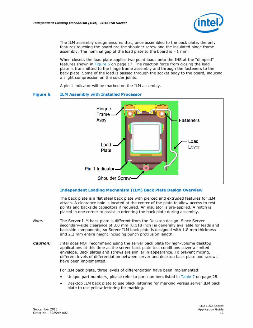
The ILM assembly design ensures that, once assembled to the back plate, the onlyfeatures touching the board are the shoulder screw and the insulated hinge frameassembly. The nominal gap of the load plate to the board is ~1 mm.
When closed, the load plate applies two point loads onto the IHS at the “dimpled”features shown in Figure 6 on page 17. The reaction force from closing the loadplate is transmitted to the hinge frame assembly and through the fasteners to theback plate. Some of the load is passed through the socket body to the board, inducinga slight compression on the solder joints.
A pin 1 indicator will be marked on the ILM assembly.
Figure 6. ILM Assembly with Installed Processor
Independent Loading Mechanism (ILM) Back Plate Design Overview
The back plate is a flat steel back plate with pierced and extruded features for ILMattach. A clearance hole is located at the center of the plate to allow access to testpoints and backside capacitors if required. An insulator is pre-applied. A notch isplaced in one corner to assist in orienting the back plate during assembly.
Note: The Server ILM back plate is different from the Desktop design. Since Serversecondary-side clearance of 3.0 mm [0.118 inch] is generally available for leads andbackside components, so Server ILM back plate is designed with 1.8 mm thicknessand 2.2 mm entire height including punch protrusion length.
Caution: Intel does NOT recommend using the server back plate for high-volume desktopapplications at this time as the server back plate test conditions cover a limitedenvelope. Back plates and screws are similar in appearance. To prevent mixing,different levels of differentiation between server and desktop back plate and screwshave been implemented.
For ILM back plate, three levels of differentiation have been implemented:
• Unique part numbers, please refer to part numbers listed in Table 7 on page 28.
• Desktop ILM back plate to use black lettering for marking versus server ILM backplate to use yellow lettering for marking.
Independent Loading Mechanism (ILM)—LGA1150 Socket
LGA1150 SocketSeptember 2013 Application GuideOrder No.: 328999-002 17

• Desktop ILM back plate using marking “115XDBP” versus server ILM back plateusing marking “115XSBP”.
Note: When reworking a BGA component or the socket that the heatsink, battery, ILM andILM back plate are removed prior to rework. The ILM back plate should also beremoved when reworking through hole mounted components in a mini-wave or solderpot). The maximum temperature for the pre-applied insulator on the ILM isapproximately 106 °C.
Figure 7. Back Plate
Shoulder Screw and Fasteners Design Overview
The shoulder screw is fabricated from carbonized steel rod. The shoulder height anddiameter are integral to the mechanical performance of the ILM. The diameterprovides alignment of the load plate. The height of the shoulder ensures the properloading of the IHS to seat the processor on the socket contacts. The design assumesthe shoulder screw has a minimum yield strength of 235 MPa.
The screws for Server ILM are different from Desktop design. The length of Server ILMscrews are shorter than the Desktop screw length to satisfy Server secondary-sideclearance limitation. Server ILM back plate to use black nickel plated screws, whereasdesktop ILM back plate to use clear plated screws. Unique part numbers, please referto Table 7 on page 28.
Note: The reference design incorporates a T-20 Torx* head fastener. The Torx* headfastener was chosen to ensure end users do not inadvertently remove the ILMassembly and for consistency with the LGA1366 socket ILM.
LGA1150 Socket—Independent Loading Mechanism (ILM)
LGA1150 SocketApplication Guide September 201318 Order No.: 328999-002

Figure 8. Shoulder Screw
Assembly of Independent Loading Mechanism (ILM) to aMotherboard
The ILM design allows a bottoms up assembly of the components to the board. See Figure 9 on page 20 for step by step assembly sequence.
1. Place the back plate in a fixture. The motherboard is aligned with the fixture.
2. Install the shoulder screw in the single hole near Pin 1 of the socket. Torque to aminimum and recommended 8 inch-pounds, but not to exceed 10 inch-pounds.
3. Install two (2) 6–32 fasteners. Torque to a minimum and recommended 8 inch-pounds, but not to exceed 10 inch-pounds.
4. Remove pick and place cover and close ILM leaving the ILM cover in place.
The thread length of the shoulder screw accommodates a nominal board thicknessesof 0.062”.
3.2
Independent Loading Mechanism (ILM)—LGA1150 Socket
LGA1150 SocketSeptember 2013 Application GuideOrder No.: 328999-002 19

Figure 9. Independent Loading Mechanism (ILM) Assembly
As indicated in Figure 10 on page 20, the shoulder screw, socket protrusion and ILMkey features prevent 180 degree rotation of ILM cover assembly with respect tosocket. The result is a specific Pin 1 orientation with respect to ILM lever.
Figure 10. Pin1 and Independent Loading Mechanism (ILM) Lever
LGA1150 Socket—Independent Loading Mechanism (ILM)
LGA1150 SocketApplication Guide September 201320 Order No.: 328999-002

Independent Loading Mechanism (ILM)Interchangeability
ILM assembly and ILM back plate built from the Intel controlled drawings are intendedto be interchangeable. Interchangeability is defined as an ILM from Vendor A willdemonstrate acceptable manufacturability and reliability with a socket body fromVendor A, B or C. ILM assembly and ILM back plate from all vendors are alsointerchangeable.
The ILM are an integral part of the socket validation testing. ILMs from each vendorwill be matrix tested with the socket bodies from each of the current vendors. Thetests would include: manufacturability, bake and thermal cycling.
See Component Suppliers on page 28 for vendor part numbers that were tested.
Note: ILMs that are not compliant to the Intel controlled ILM drawings can not be assured tobe interchangeable.
Markings
There are four markings on the ILM:
• 115XLM: Font type is Helvetica Bold - minimum 6 point (2.125 mm).
• Manufacturer's insignia (font size at supplier's discretion).
• Lot identification code (allows traceability of manufacturing date and location).
• Pin 1 indicator on the load plate.
All markings must be visible after the ILM is assembled on the motherboard.
115XLM and the manufacturer's insignia can be ink stamped or laser marked on theside wall.
Independent Loading Mechanism (ILM) Cover
Intel has developed an ILM Cover that will snap onto the ILM for the LGA115x socketfamily. The ILM cover is intended to reduce the potential for socket contact damagefrom operator and customer fingers being close to the socket contacts to remove orinstall the pick and place cap. The ILM Cover concept is shown in Figure 11 on page22.
The ILM Cover is intended to be used in place of the pick and place cover once the ILMis assembled to the motherboard. The ILM will be offered with the ILM Cover pre-assembled as well as offered as a discrete component.
ILM Cover features:
• Pre-assembled by the ILM vendors to the ILM load plate. It will also be offered asa discrete component.
• The ILM cover will pop off if a processor is installed in the socket, and the ILMCover and ILM are from the same manufacturer.
• ILM Cover can be installed while the ILM is open.
• Maintain inter-changeability between validated ILM vendors for LGA115x socket,with the exception noted below.
3.3
3.4
3.5
Independent Loading Mechanism (ILM)—LGA1150 Socket
LGA1150 SocketSeptember 2013 Application GuideOrder No.: 328999-002 21

• The ILM cover for the LGA115x socket will have a flammability rating of V-2 perUL 60950-1.
Note: The ILM Cover pop off feature is not supported if the ILM Covers are interchanged ondifferent vendor’s ILMs.
Figure 11. Independent Loading Mechanism (ILM) Cover
As indicated in Figure 11 on page 22, the pick and place cover should remain installedduring ILM assembly to the motherboard. After assembly the pick and place cover isremoved, the ILM Cover installed and the ILM mechanism closed. The ILM Cover isdesigned to pop off if the pick and place cover is accidentally left in place and the ILMclosed with the ILM Cover installed. This is shown in Figure 12 on page 23.
LGA1150 Socket—Independent Loading Mechanism (ILM)
LGA1150 SocketApplication Guide September 201322 Order No.: 328999-002

Figure 12. ILM Cover and PnP Cover Interference
As indicated in Figure 12 on page 23, the pick and place cover cannot remain in placeand used in conjunction with the ILM Cover. The ILM Cover is designed to interfereand pop off if the pick and place cover is unintentionally left in place. The ILM coverwill also interfere and pop off if the ILM is closed with a processor in place in thesocket.
Independent Loading Mechanism (ILM)—LGA1150 Socket
LGA1150 SocketSeptember 2013 Application GuideOrder No.: 328999-002 23
4.0 LGA1150 Socket and ILM Specifications
This chapter describes the following specifications and requirements:
• Mechanical Specifications on page 24
• Electrical Requirements on page 25
• Environmental Requirements on page 26
Mechanical Specifications
Component Mass
Table 3. Socket Component Mass
Component Mass
Socket Body, Contacts and PnP Cover 10 g
ILM Cover 29 g
ILM Back Plate 38 g
Package / Socket Stackup Height
The following table provides the stackup height of a processor in the 1150-land LGApackage and LGA1150 socket with the ILM closed and the processor fully seated in thesocket.
Table 4. 1150-land Package and LGA1150 Socket Stackup Height
Component Stackup Height Note
Integrated Stackup Height (mm) From Top of Board to Top of IHS 7.781 ± 0.335 mm 2
Socket Nominal Seating Plane Height 3.4 ± 0.2 mm 1
Package Nominal Thickness (lands to top of IHS) 4.381 ± 0.269 mm 1
Note:1. This data is provided for information only, and should be derived from: (a) the height of the socket
seating plane above the motherboard after reflow, given in Socket Mechanical Drawings, (b) the height ofthe package, from the package seating plane to the top of the IHS, and accounting for its nominalvariation and tolerances that are given in the corresponding processor datasheet.
2. The integrated stackup height value is a RSS calculation based on current and planned processors thatwill use the ILM design.
Loading Specifications
The socket will be tested against the conditions listed in Thermal Solution Quality andReliability Requirements Chapter of the Processor Thermal Mechanical DesignGuidelines (see Related Documents section) with heatsink and the ILM attached,under the loading conditions outlined in this section.
4.1
LGA1150 Socket—LGA1150 Socket and ILM Specifications
LGA1150 SocketApplication Guide September 201324 Order No.: 328999-002

Table 5 on page 25 provides load specifications for the LGA1150 socket with the ILMinstalled. The maximum limits should not be exceeded during heatsink assembly,shipping conditions, or standard use condition. Exceeding these limits during test mayresult in component failure. The socket body should not be used as a mechanicalreference or load-bearing surface for thermal solutions.
Table 5. Socket and ILM Mechanical Specifications
Parameter Minimum Maximum Notes
ILM static compressive load on processorIHS 311 N [70 lbf] 600 N [135 lbf] 3, 4, 7, 8
Heatsink static compressive load 0 N [0 lbf] 222 N [50 lbf] 1, 2, 3
Total static compressive Load (ILM plusHeatsink) 311 N [70 lbf] 822 N [185 lbf] 3, 4, 7, 8
Dynamic Compressive Load (with heatsinkinstalled) N/A 712 N [160 lbf] 1, 3, 5, 6
Pick & Place cover insertion force N/A 10.2 N [2.3 lbf] –
Pick & Place cover removal force 2.2N [0.5 lbf] 7.56 N [1.7 lbf] 9
Load lever actuation forceN/A
20.9N [4.7lbf] in the verticaldirection 10.2 N [2.3 lbf] in
the lateral direction.–
Maximum heatsink mass N/A 500g 10
Notes:1. These specifications apply to uniform compressive loading in a direction perpendicular to the IHS top
surface.2. This is the minimum and maximum static force that can be applied by the heatsink and its retention
solution to maintain the heatsink to IHS interface. This does not imply the Intel reference TIM is validatedto these limits.
3. Loading limits are for the LGA1150 socket.4. This minimum limit defines the static compressive force required to electrically seat the processor onto
the socket contacts. The minimum load is a beginning of life load.5. Dynamic loading is defined as a load a 4.3 m/s [170 in/s] minimum velocity change average load
superimposed on the static load requirement.6. Test condition used a heatsink mass of 500 gm [1.102 lb.] with 50 g acceleration (table input) and an
assumed 2X Dynamic Acceleration Factor (DAF). The dynamic portion of this specification in the productapplication can have flexibility in specific values. The ultimate product of mass times acceleration plusstatic heatsink load should not exceed this limit.
7. The maximum BOL value and must not be exceeded at any point in the product life.8. The minimum value is a beginning of life loading requirement based on load degradation over time.9. The maximum removal force is the flick up removal upwards thumb force (measured at 45°), not
applicable to SMT operation for system assembly. Only the minimum removal force is applicable tovertical removal in SMT operation for system assembly.
10.The maximum heatsink mass includes the core, extrusion, fan and fasteners. This mass limit is evaluatedusing the POR heatsink attach to the PCB.
Electrical Requirements
LGA1150 socket electrical requirements are measured from the socket-seating planeof the processor to the component side of the socket PCB to which it is attached. Allspecifications are maximum values (unless otherwise stated) for a single socketcontact, but includes effects of adjacent contacts where indicated.
4.2
LGA1150 Socket and ILM Specifications—LGA1150 Socket
LGA1150 SocketSeptember 2013 Application GuideOrder No.: 328999-002 25

Table 6. Electrical Requirements for LGA1150 Socket
Parameter Value Comment
Mated loop inductance, Loop
<3.6nH
The inductance calculated for two contacts,considering one forward conductor and one returnconductor. These values must be satisfied at theworst-case height of the socket.
Socket Average Contact Resistance(EOL)
19 mOhm
The socket average contact resistance target iscalculated from the following equation: sum (Ni XLLCRi) / sum (Ni)• LLCRi is the chain resistance defined as the
resistance of each chain minus resistance ofshorting bars divided by number of lands in thedaisy chain.
• Ni is the number of contacts within a chain.• I is the number of daisy chain, ranging from 1
to 119 (total number of daisy chains).The specification listed is at room temperatureand has to be satisfied at all time.
Max Individual Contact Resistance(EOL)
100 mOhm
The specification listed is at room temperatureand has to be satisfied at all time. Socket ContactResistance: The resistance of the socket contact,solderball, and interface resistance to theinterposer land; gaps included.
Bulk Resistance Increase ≤3 mΩ The bulk resistance increase per contact from25 °C to 100 °C.
Dielectric Withstand Voltage 360 Volts RMS
Insulation Resistance 800 MΩ
Environmental Requirements
Design, including materials, shall be consistent with the manufacture of units thatmeet the following environmental reference points.
The reliability targets in this section are based on the expected field use environmentfor these products. The test sequence for new sockets will be developed using theknowledge-based reliability evaluation methodology, which is acceleration factordependent. A simplified process flow of this methodology can be seen in Figure 13 onpage 27.
4.3
LGA1150 Socket—LGA1150 Socket and ILM Specifications
LGA1150 SocketApplication Guide September 201326 Order No.: 328999-002

Figure 13. Flow Chart of Knowledge-Based Reliability Evaluation Methodology
A detailed description of this methodology can be found at:
ftp://download.intel.com/technology/itj/q32000/pdf/reliability.pdf.
LGA1150 Socket and ILM Specifications—LGA1150 Socket
LGA1150 SocketSeptember 2013 Application GuideOrder No.: 328999-002 27

Appendix A Component Suppliers
Note: The part numbers listed below identifies the reference components. End-users areresponsible for the verification of the Intel enabled component offerings with thesupplier. These vendors and devices are listed by Intel as a convenience to Intel'sgeneral customer base, but Intel does not make any representations or warrantieswhatsoever regarding quality, reliability, functionality, or compatibility of thesedevices. Customers are responsible for thermal, mechanical, and environmentalvalidation of these solutions. This list and/or these devices may be subject to changewithout notice.
Table 7. LGA1150 Socket and ILM Components
Item Intel PN Foxconn Molex Tyco Lotes ITW
LGA1150 Socket G27433-002
PE115027-4041-01F
475963032
2134930-1
ACA-ZIF-138-P01
NA
LGA115X ILM withcover
G11449-002
PT44L61-6411
N/A 2013882-8
ACA-ZIF-078-Y28
FT1002-A-F
LGA115X ILM withoutcover
E36142-002
PT44L61-6401
475968855
2013882-3
ACA-ZIF-078-Y19
FT1002-A
LGA115X ILM coveronly
G12451-001
012-1000-5377
N/A 1-2134503-1
ACA-ZIF-127-P01
FT1002-F
Desktop Backplatewith screws
E36143-002
PT44P19-6401
475969930
2069838-2
DCA-HSK-144-Y09
FT1002-B-CD
1U Backplate (withscrews)
E66807-001
PT44P18-6401
N/A N/A DCA-HSK-157-Y03
NA
Notes:1. The 1U Back Plate is a point solution for uP servers. This has not been validated for desktop design. This
should be used only were the clearance between the back of the motherboard and chassis is limited suchas 1U rack servers.
2. Individual ILM covers are made available for post-sales support
Table 8. Supplier Contact Information
Supplier Contact Phone Email
Foxconn Eric Ling +1 503 693 3509 x225 [email protected]
ITW Fastex Chak Chakir +1 512 989 7771 [email protected]
Lotes Co., Ltd. Windy Wang +1 604 721 1259 [email protected]
Molex Carol Liang +86 21 504 80889 x3301 [email protected]
Tyco Alex Yeh (primarycontact)
+886 2 21715280 [email protected]
Stanley Yen(secondary contact)
+886 2 21715291 [email protected]
The enabled components may not be currently available from all suppliers. Contactthe supplier directly to verify time of component availability.
LGA1150 Socket—Component Suppliers
LGA1150 SocketApplication Guide September 201328 Order No.: 328999-002
Appendix B Mechanical Drawings
The following table lists the mechanical drawings included in this appendix.
Table 9. Mechanical Drawing List
Drawing Description Figure Number / Location
Socket / Heatsink / ILM Keep-out Zone Primary Side (Top) Figure 14 on page 30
Socket / Heatsink / ILM Keep-out Zone Secondary Side (Bottom) Figure 15 on page 31
Socket / Processor / ILM Keep-out Zone Primary Side (Top) Figure 16 on page 32
Socket / Processor / ILM Keep-out Zone Secondary Side(Bottom)
Figure 17 on page 33
Mechanical Drawings—LGA1150 Socket
LGA1150 SocketSeptember 2013 Application GuideOrder No.: 328999-002 29

Figure 14. Socket/Heatsink / ILM Keep-out Zone Primary Side (Top)
LGA1150 Socket—Mechanical Drawings
LGA1150 SocketApplication Guide September 201330 Order No.: 328999-002

Figure 15. Socket / Heatsink / ILM Keep-out Zone Secondary Side (Bottom)
Mechanical Drawings—LGA1150 Socket
LGA1150 SocketSeptember 2013 Application GuideOrder No.: 328999-002 31

Figure 16. Socket / Processor / ILM Keep-out Zone Primary Side (Top)
LGA1150 Socket—Mechanical Drawings
LGA1150 SocketApplication Guide September 201332 Order No.: 328999-002

Figure 17. Socket / Processor / ILM Keep-out Zone Secondary Side (Bottom)
Mechanical Drawings—LGA1150 Socket
LGA1150 SocketSeptember 2013 Application GuideOrder No.: 328999-002 33

Appendix C Heatsink Back Plate Drawings
This heatsink back plate design is intended to adapt as a reference for OEMs that usethreaded fasteners on customized thermal solution, to comply with the mechanicaland structural requirements for the LGA115x socket. The heatsink back plate does nothave to provide additional load for socket solder joint protect. Structural designstrategy for the heatsink is to provide sufficient load for the Thermal Interface Material(TIM) and to minimize stiffness impact on the motherboard.
Note: Design modifications for specific application and manufacturing are the responsibilityof OEM and the listed vendors for customized system implementation and validation.These vendors and devices are listed by Intel as a convenience to Intel's generalcustomer base, but Intel does not make any representations or warranties whatsoeverregarding quality, reliability, functionality, or compatibility of these devices. Customersare responsible for thermal, mechanical, and environmental validation of thesesolutions. This list and/or these devices may be subject to change without notice.
Please refer to the motherboard keep-out zone listed in the LGA1150 SocketApplication Guide to ensure compliant with the heatsink back plate implementation. Figure 18 on page 35 is the heatsink back plate keep-in zone for the designimplementation.
Table 10 on page 34 lists the mechanical drawings included in this appendix. Table11 on page 34 lists the mechanical drawings
Table 10. Mechanical Drawing List
Drawing Description Figure Number/Location
Heatsink Back Plate Keep-in Zone Figure 18 on page 35
Heatsink Back Plate Figure 19 on page 36
Table 11. Supplier Contact Information
Supplier Contact Phone Email
CCI (Chaun Choung TechnologyCorp.)
Monica Chih +886-2-29952666x1131
The enabled components may not be currently available from supplier. Contact thesupplier directly to verify time of component availability.
LGA1150 Socket—Heatsink Back Plate Drawings
LGA1150 SocketApplication Guide September 201334 Order No.: 328999-002
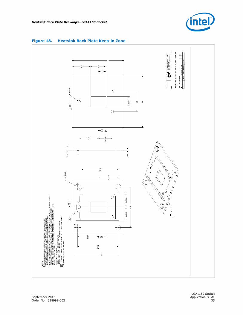
Figure 18. Heatsink Back Plate Keep-in Zone
Heatsink Back Plate Drawings—LGA1150 Socket
LGA1150 SocketSeptember 2013 Application GuideOrder No.: 328999-002 35

Figure 19. Heatsink Back Plate
LGA1150 Socket—Heatsink Back Plate Drawings
LGA1150 SocketApplication Guide September 201336 Order No.: 328999-002