LF(M) - WordPress.com · LF(M) Specifications Dimensions See Installation Drawings on page 3-4 for...
7
LF(M) High Viscosity Filter Assemblies Low pressure filter assemblies optimized for high flow hydraulic, high viscosity lube and heavily contaminated fuel applications. Max Operating Pressure: 150 psi (10 bar) Available options up to 1000 psi (68.9 bar) hyprofiltration .com/LF
Transcript of LF(M) - WordPress.com · LF(M) Specifications Dimensions See Installation Drawings on page 3-4 for...

LF(M)High Viscosity Filter AssembliesLow pressure filter assemblies optimized for high flow hydraulic, high viscosity lube and heavily contaminated fuel applications.
Max Operating Pressure: 150 psi (10 bar)Available options up to 1000 psi (68.9 bar)
hyprofiltration.com/LF

Filtration starts with the filter.The oversized coreless filter element in every LF delivers lower ISO Codes over a long element lifespan to ensure low disposal impact, simultaneously reducing your environmental footprint and your bottom line. To top it off, select elements come standard with an integral zero-leak bypass so with every filter change you get a new bypass along with peace of mind.
Built for industrial use.Constructed from heavy duty carbon steel (standard) or the optional 304 or 316 stainless steel, the LF filter housings are designed to excel in even the toughest industrial conditions. Multiround units go even further to provide increased capacity whether you’re operating with incredibly high viscosity oils, extreme flow rates or need extended service intervals.
Element configuration & media options.With media options down to β0.9[C] > 1000, insoluble varnish removal and water absorbing options, you get the perfect element for your application, every time. Element configurations include Hy-Pro HP106 and HP107 coreless style elements with integral, zero-leak bypass valves. For those plants using 8314 style industry standard elements, the HP8314 offers an improved bypass valve design.
Setting the new standard.Sampling and condition monitoring are no longer optional, they’re a necessity. That’s why every LF comes standard with sample ports and green to red true ∆P gages that indicate exact element condition at all times. With access to accurate system cleanliness conditions, you’ll know exactly how well your filtration is performing.
Minimize the mess.Top loading filter housings minimize the mess from element services and changes. And with the easy open swing bolt lid design, you’ll be back to filtering your fluids without having to search for all those lost parts.
Seamlessly integrated into your systems.Multiple connection options and port customization provide the flexibility to integrate LF directly into existing re-circulating or auxiliary side loop and dispensing lines to improve fluid cleanliness and optimize existing assets. Get filtration exactly where you need it without extra expense of installing new plumbing and electrical.

Ø 0.75 in[19 mm]
14.8 in[376 mm]
14.8 in[376 mm]
9.5 in[241 mm]
Mounting Holes
9.5 in[241 mm]
Mounting Holes14.8 in[376 mm]
14.8 in[376 mm]
9.5 in[241 mm]
Mounting Holes
9.5 in[241 mm]
Mounting Holes
50.5 in[1283 mm]
3.5 in[89 mm]
8.6 in[219 mm]
7.0 in[178 mm]
Sample Port Sample Port Drain Port
ΔP Gauge
Vent Port
32.0 in[813 mm]
7.0 in[178 mm]
3.5 in[89 mm]
8.6 in[219 mm]
Sample Port Sample Port Drain Port
ΔP Gauge
Vent Port
20.0 in[508 mm]
Minimum Distance forElement Removal
37.0 in[399 mm]
Minimum Distance forElement Removal
Ø 0.75 in[19 mm]
Flow Flow
LF Installation DrawingsLF (L18) Installation Drawing LF (L36) Installation Drawing
hyprofiltration.com/LF

GMinimum Distance for
Element Removal
Outlet Sample Port
C
Vent Port
Drain
ΔP Gauge
Inlet Sample Port
A
E
BD
F
Drain
LFM Installation Drawings
hyprofiltration.com/LF
Series Number of Elements
Port Size
Vessel Diameter
A B C D E F G Weight
LFM 3 2 16.0 in 27.1 in 13.0 in 14.1 in 16.8 in 26.0 in 78.5 in 37.0 in 465.0 lb40.6 cm 68.8 cm 33.0 cm 35.8 cm 42.7 cm 66.0 cm 199.4 cm 94.0 cm 210.9 kg
3 16.0 in 27.1 in 13.0 in 14.1 in 16.8 in 26.0 in 78.5 in 37.0 in 465.0 lb40.6 cm 68.8 cm 33.0 cm 35.8 cm 42.7 cm 66.0 cm 199.4 cm 94.0 cm 210.9 kg
4 16.0 in 27.1 in 13.0 in 14.1 in 16.8 in 26.0 in 78.5 in 37.0 in 65.0 lb40.6 cm 68.8 cm 33.0 cm 35.8 cm 42.7 cm 66.0 cm 199.4 cm 94.0 cm 29.5 kg
4 2 18.0 in 29.8 in 13.0 in 16.1 in 17.5 in 26.0 in 83.0 in 37.0 in 550.0 lb45.7 cm 75.7 cm 33.0 cm 40.9 cm 44.5 cm 66.0 cm 210.8 cm 94.0 cm 249.5 kg
3 18.0 in 29.8 in 13.0 in 16.1 in 17.5 in 26.0 in 83.0 in 37.0 in 550.0 lb45.7 cm 75.7 cm 33.0 cm 40.9 cm 44.5 cm 66.0 cm 210.8 cm 94.0 cm 249.5 kg
4 18.0 in 29.8 in 13.0 in 16.1 in 17.5 in 26.0 in 83.0 in 37.0 in 550.0 lb45.7 cm 75.7 cm 33.0 cm 40.9 cm 44.5 cm 66.0 cm 210.8 cm 94.0 cm 249.5 kg
9 3 24.0 in 32.3 in 13.0 in 23.5 in 23.7 in 37.3 in 89.0 in 37.0 in 645.0 lb61.0 cm 82.0 cm 33.0 cm 59.7 cm 60.2 cm 94.7 cm 226.1 cm 94.0 cm 292.6 kg
4 24.0 in 32.3 in 13.0 in 23.5 in 23.7 in 37.3 in 89.0 in 37.0 in 645.0 lb61.0 cm 82.0 cm 33.0 cm 59.7 cm 60.2 cm 94.7 cm 226.1 cm 94.0 cm 292.6 kg
6 24.0 in 32.3 in 13.0 in 23.5 in 23.7 in 37.3 in 89.0 in 37.0 in 645.0 lb61.0 cm 82.0 cm 33.0 cm 59.7 cm 60.2 cm 94.7 cm 226.1 cm 94.0 cm 292.6 kg
1Dimensions are approximations taken from base model and will vary according to options chosen and customer sizing requirements.

hyprofiltration.com/LF
Filter Sizing Guidelines
ΔP Factors1 Model Length Units MediaVTM 05M 1M 3M 6M 10M 16M 25M **W
LF 16/18 psid/gpm 0.0628 0.0473 0.0463 0.0391 0.0303 0.0271 0.0266 0.0256 0.0046bard/lpm 0.0011 0.0009 0.0008 0.0007 0.0006 0.0005 0.0005 0.0005 0.0001
36/39 psid/gpm 0.0440 0.0331 0.0324 0.0273 0.0212 0.0190 0.0186 0.0179 0.0032bard/lpm 0.0008 0.0006 0.0006 0.0005 0.0004 0.0003 0.0003 0.0003 0.0001
LFM3 36/39 psid/gpm 0.0122 0.0092 0.0081 0.0055 0.0051 0.0045 0.0041 0.0035 0.0029bard/lpm 0.0002 0.0002 0.0001 0.0001 0.0001 0.0001 0.0001 0.0001 0.0001
LFM4 36/39 psid/gpm 0.0091 0.0069 0.0067 0.0048 0.0044 0.004 0.0037 0.0032 0.0025bard/lpm 0.0002 0.0001 0.0001 0.0001 0.0001 0.0001 0.0001 0.0001 0.00005
Model Length Units Media1A 3A 6A 10A 16A 25A
LF 16/18 psid/gpm 0.0514 0.0434 0.0336 0.0302 0.0295 0.0284bard/lpm 0.0009 0.0008 0.0006 0.0005 0.0005 0.0005
36/39 psid/gpm 0.0360 0.0304 0.0235 0.0211 0.0207 0.0199bard/lpm 0.0007 0.0006 0.0004 0.0004 0.0004 0.0004
LFM3 36/39 psid/gpm 0.0073 0.0049 0.0046 0.0040 0.0037 0.0031bard/lpm 0.0001 0.0001 0.0001 0.0001 0.0001 0.0001
LFM4 36/39 psid/gpm 0.0060 0.0043 0.0040 0.0036 0.0033 0.0029bard/lpm 0.0001 0.0001 0.0001 0.0001 0.0001 0.0001
1Max flow rates and ΔP factors assume υ = 150 SUS, 32 cSt. See filter assembly sizing guideline for viscosity conversion formula.
Filter Assembly Sizing GuidelinesEffective filter sizing requires consideration of flow rate, viscosity (operating and cold start), fluid type and degree of filtration. When properly sized, bypass during cold start can be avoided/minimized and optimum element efficiency and life achieved. The filter assembly differential pressure values provided for sizing differ for each media code, and assume 32 cSt (150 SUS) viscosity and 0.86 fluid specific gravity. Use the following steps to calculate clean element assembly pressure drop.
Sizing recommendations to optimize performance and permit future flexibility• To avoid or minimize bypass during cold start the actual
assembly clean ΔP calculation should be repeated for start-up conditions if cold starts are frequent.
• Actual assembly clean ΔP should not exceed 10% of bypass ∆P gauge/indicator set point at normal operating viscosity.
• If suitable assembly size is approaching the upper limit of the recommended flow rate at the desired degree of filtration consider increasing the assembly to the next larger size if a finer degree of filtration might be preferred in the future. This practice allows the future flexibility to enhance fluid cleanliness without compromising clean ΔP or filter element life.
• Once a suitable filter assembly size is determined consider increasing the assembly to the next larger size to optimize filter element life and avoid bypass during cold start.
• When using water glycol or other specified synthetics, we recommend increasing the filter assembly by 1~2 sizes.
Step 1: Calculate ΔP coefficient for actual viscosity
Using Saybolt Universal Seconds (SUS)
ΔP Coefficient =
Actual Operating Viscosity1 (SUS)
X
Actual Specific Gravity
150 0.86
Using Centistokes (cSt)
ΔP Coefficient =
Actual Operating Viscosity1 (cSt)
X
Actual Specific Gravity
32 0.86
Step 2: Calculate actual clean filter assembly ΔP at both operating and cold start viscosity
Actual Assembly Clean ΔP
= Flow Rate X ΔP Coefficient
(from Step 1) X Assembly ΔP Factor (from sizing table)
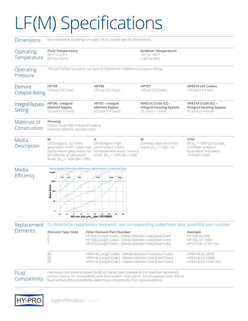
LF(M) SpecificationsDimensions See Installation Drawings on page 3-4 for model specific dimensions.
Operating Temperature
Fluid Temperature30°F to 225°F(0°C to 105°C)
Ambient Temperature-4°F to 140°F(-20C to 60C)
Operating Pressure
150 psi (10 bar) standard, see Special Options for additional pressure ratings.
Element Collapse Rating
HP105150 psi (10.3 bar)
HP106150 psi (10.3 bar)
HP107150 psi (10.3 bar)
HP8314 (All Codes)150 psi (10.3 bar)
Integral Bypass Setting
HP106 – integral element bypass25 psid (1.7 bard)
HP107 – Integral element bypass50 psid (3.4 bard)
HP8314 (Code 82) – Integral housing bypass25 psid (1.7 bard)
HP8314 (Code 83) – Integral housing bypass50 psid (3.4 bard)
Materials of Construction
HousingCarbon steel with industrial coatingOptional 304/316 stainless steel
Media Description
MG8 Dualglass, our latest generation of DFE rated, high performance glass media for all hydraulic & lubrication fluids. βx[C] = 1000 (βx = 200)
AG8 Dualglass high performance media combined with water removal scrim. βx[C] = 1000 (βx = 200)
WStainless steel wire mesh media βx[C] = 2 (βx = 2)
VTMβ0.9[C] = 1000 particulate, insoluble oxidation by-product and water removal media
Media Efficiency 1M 3M 6M 10M 16M 25M
Micron size µm[C] (per ISO16889)
10
100
1,000
10,000
Beta
Rat
io
Glass Media Filtration Efficiency (Beta Ratio) vs Micron Size
122 2516121076542.5
Replacement Elements
To determine replacement elements, use corresponding codes from your assembly part number:
Element Type Code567
Filter Element Part NumberHP105L [ Length Code ] – [ Media Selection Code ][ Seal Code ]HP106L [ Length Code ] – [ Media Selection Code ][ Seal Code ]HP107L [ Length Code ] – [ Media Selection Code ][ Seal Code ]
ExampleHP105L36–6ABHP106L18–10MVHP107L36–VTM710V
8X8285
HP8314L [ Length Code ] – [ Media Selection Code ][ Seal Code ]HP8314L [ Length Code ] – [ Media Selection Code ][ Seal Code ]HP8314L [ Length Code ] – [ Media Selection Code ][ Seal Code ]
HP8314L39–25WVHP8314L16–12MBHP8314L39–16ME–WS
Fluid Compatibility
Petroleum and mineral based fluids, #2 diesel fuels (standard). For specified synthetics contact factory for compatibility with fluorocarbon seal option. For phosphate ester (P9) or skydrol fluid (S9) compatibility select fluid compatibility from special options.
hyprofiltration.com/LF
Want to find out more? Get in [email protected]+1 317 849 3535© 2017 Hy-Pro Corporation. All rights reserved. MK TLITFA S-LF-022117-BC
Filtration starts with the filter.Lower ISO Codes: Lower Total Cost of Ownership Hy-Pro filter elements deliver lower operating ISO Codes so you know your fluids are always clean, meaning lower total cost of ownership and reducing element consumption, downtime, repairs, and efficiency losses.
Advanced Media Options DFE glass media maintaining efficiency to β0.7[c] > 1000, Dualglass + water removal media to remove free and emulsified water, stainless wire mesh for coarse filtration applications, and Dynafuzz stainless fiber media for EHC and aerospace applications.
DFE Rated Filter Elements DFE is Hy-Pro’s proprietary testing process which extends ISO 16889 Multi Pass testing to include real world, dynamic conditions and ensures that our filter elements excel in your most demanding hydraulic and lube applications.
Delivery in days, not weeks From a massive inventory of ready-to-ship filter elements to flexible manufacturing processes, Hy-Pro is equipped for incredibly fast response time to ensure you get your filter elements and protect your uptime.
Upgrade Your Filtration Keeping fluids clean results in big reliability gains and upgrading to Hy-Pro filter elements is the first step to clean oil and improved efficiency.
More than just filtration Purchasing Hy-Pro filter elements means you not only get the best filters, you also get the unrivaled support, training, knowledge and expertise of the Hy-Pro team working shoulder-to-shoulder with you to eliminate fluid contamination.