
??LFG PDD ?? 051206 for SGS 051210 051212 Revised Xiaping... · - 3 - There is no shaft in the...
50
- 1 - CLEAN DEVELOPMENT MECHANISM PROJECT DESIGN DOCUMENT FORM (CDM-PDD) Version 02 – (in effect as of: 1 July 2004) ① CONTENTS A. General description of project activity B. Application of a baseline methodology C. Duration of the project activity / Crediting period D. Application of a monitoring methodology and plan E. Estimation of GHG emissions by sources F. Environmental impacts G. Stakeholders’ comments Annexes Annex 1: Contact information on participants in the project activity Annex 2: Information regarding public funding Annex 3: Baseline information Annex 4: Monitoring plan Annex 5. List of Abbreviations ① The PDD form is revised according to EB 19 Report Annex 14: REVISED GUIDELINES FOR COMPLETING THE FORMS: CDM-PDD, CDM-NMB AND CDM-NMM, 13 May, 2005.
Transcript of ??LFG PDD ?? 051206 for SGS 051210 051212 Revised Xiaping... · - 3 - There is no shaft in the...

- 1 -
CLEAN DEVELOPMENT MECHANISM
PROJECT DESIGN DOCUMENT FORM (CDM-PDD)
Version 02 – (in effect as of: 1 July 2004) ①
CONTENTS
A. General description of project activity
B. Application of a baseline methodology
C. Duration of the project activity / Crediting period
D. Application of a monitoring methodology and plan
E. Estimation of GHG emissions by sources
F. Environmental impacts
G. Stakeholders’ comments
Annexes
Annex 1: Contact information on participants in the project activity
Annex 2: Information regarding public funding
Annex 3: Baseline information
Annex 4: Monitoring plan
Annex 5. List of Abbreviations
① The PDD form is revised according to EB 19 Report Annex 14: REVISED GUIDELINES
FOR COMPLETING THE FORMS: CDM-PDD, CDM-NMB AND CDM-NMM, 13 May,
2005.

- 2 -
SECTION A. General description of project activity
A.1 Title of the project activity:
>>
Shenzhen Xiaping Landfill Gas Collection and Utilization Project
Version number of the document: 2
Date: Oct, 15th 2005.
A.2. Description of the project activity:
>>
The Shenzhen Xiaping Landfill Gas Collection and Utilization Project (hereafter referred to
as the Proposed Project) developed by Shenzhen Lisai Development Co., Ltd (hereafter
referred to as the Project Owner) is a landfill gas (LFG) collection and utilization project in
the Xiaping Landfill of the Luohu District, Shenzhen City, Guangdong Province, P.R.China.
The project will have an LFG upgrade system with 500m3/h processing capacity. The
proposed project will invest in construction of a LFG collection system covered the Xiaping
Landfill, and utilize the collected LFG to produce Compressed Purified Landfill Gas (CPLG)
and to generate power. Excess LFG, all gas collected during the period when LFG upgrade
system is not operated will be flared.
Xiaping Landfill is the largest operated sanitary landfill in Shenzhen City at present. It was
put into operation in Oct, 1997 with 25 years of designed operation period. It receives an
average of 3,000t of domestic waste per day mainly from Luohu District and Futian District.
With more than 6Mt domestic waste been filled, the maximal landfill depth is about 60m and
the estimated LFG generation rate is about 300,000~500,000m3 per day at present and will be
increased in the future with more domestic waste to be filled.
The main components of LFG are methane (CH4, 50% content rate) and carbon dioxide
(CO2), which is one of six categories of greenhouse gases (GHGs) that has high Global
Warming Potential (GWP). Since there is no mandatory requirement on LFG collection,
utilization or flaring in China, the LFG arising from the most landfills includes the Xiaping
Landfill is uncontrolled release into the atmosphere currently. The uncontrolled release of
methane will have negative effects on global climate.
The objective of the Proposed Project is to collect and utilize the LFG of the Xiaping Landfill.
The Project Owner has signed cooperation agreement with the Shenzhen Xiaping Landfill in
May, 2005. According to the cooperation agreement, the Project Owner should pay for
collection and utilization of each cubic meter of LFG to Shenzhen Xiaping Landfill, while the
Project Owner owns all benefit being generated from collection and utilization of LFG. The
Proposed Project involves of investing and operating three main activities:
(1) Construction and operation of LFG collection system. The LFG arising from the solid
wastes is concentrated in the vertical shaft and extracted to the ground by Root’s blower.

- 3 -
There is no shaft in the Xiaping Landfill prior to the Proposed Project. All vertical shafts are
new build during implementation of the Proposed Project.
(2) Construction and operation of LFG upgrades to CPLG system and LFG power plant.
Limited by investment, the LFG utilization system will be constructed stage by stage. The
first stage with 500m3/h capacity will put into operation in early 2006. Through
implementing of this system, about 500m3/h of LFG will be upgraded to automobile fuel
through compression, filtration,desiccation and pressure swing adsorption. LFG upgrade to
CPLG system is stage by stage. The output of the LFG upgrade system is used as CPLG in
the vehicles to substitute gasoline for transporting solid wastes to the Xiaping Landfill. With
the CDM revenue of the Proposed Project to compensate investment and operation cost of
subsequent system, the Project Owner will extend LFG utilization through construction of the
second stage of LFG upgrade to CPLG system (1000 m3/h, at the end of 2006) and the
LFG power plant (total installed capacity 8MW, from 2007 to 2013).
(3) Construction and operation of a flaring system, excess LFG, all gas collected during the
period when LFG upgrade system is not operated will be flared.
The implementing of the Proposed Project will convert the extracted LFG to CO2 and then
released to the atmosphere. It will achieve the greenhouse gas (GHG) emission reductions by
avoiding direct methane venting from the business-as-usual scenario. The emission reductions
generated through substitution of gasoline by CPLG is not claimed in this PDD. The
cumulative estimated GHGs emission reduction of the Proposed Project is 5,741,878 tCO2e,
from 2006 to 2015. Technologies to be adopted by the Proposed Project are commonly used
in the PRC and have been approved as reliable with years of experience.
The Project Owner is a specialized company that has participate in design and construction of
several solid waste/dangerous waste landfills (pleases see Section A.3 for detail). The
technology to be applied in the LFG collection system and flaring system is mature in China.
Though the technology of LFG upgrade to CPLG is for the first time to be commercially
applied in China, similar technology has been mature and popularized in textile and chemical
industry. Based on years of study and test carried out by the Department of Environmental
Science and Engineering of Tsinghua University, LFG upgrade to CPLG technology has been
approved by the Ministry of Construction. The Department of Environmental Science and
Engineering of Tsinghua University will provide technology support to the Proposed Project,
therefore to promote utilization of LFG upgrade to CPLG technology and increase LFG
collection and utilization in China.
The Proposed Project clearly fits into the sustainable development priority of the PRC, and its
successful implementation will
(1) Greatly reduce environmental health risks, avoid bad odor and the potential for explosions
in the local surroundings thus to optimize the use of natural resources by avoid uncontrolled
release of LFG.
(2) Demonstrate clean technology with economic benefits and promote better management of

- 4 -
operated landfills throughout China, which could be replicated across the region.
(3) Promote capacity building and technology transfer of clean technologies, conserves
natural resources and increase employment opportunities in the area where the Proposed
Project is sited.
(4) Promote use of upgraded LFG as automobile fuel thus reduce natural gas consumption and
promote the implementation of the “Clean Vehicle Action” in Shenzhen city to some extent.
A.3. Project participants:
>>
Project Participants to the Proposed Project activity are as following:
Table 1....Information of project participants
Name of Party involved
(*)
((host) indicates a host
Party)
Private and/or public entity(ies)
project participants (*)
(as applicable)
Kindly indicate if
the Party involved
wishes to be
considered as
project participant
(Yes/No)
P. R. of China (host ) No
Shenzhen Lisai Development Co. Ltd
(project owner) Yes
(*) In accordance with the CDM modalities and procedures, at the time of making the CDM-PDD public at the stage of
validation, a Party involved may or may not have provided its approval. At the time of requesting registration, the approval
by the Party(ies) involved is required.
The following are the main Project Participants:
Project Owner: Shenzhen Lisai Development Co., Ltd. is the owner of the Proposed Project
which conducts design, investment, construction, operation and management of the Proposed
Project activities.
Shenzhen Lisai Development Co., Ltd is a private environmental protection company
established in 2000. The company draws rich experience in advanced environmental
technology research, design, production, installation, shakedown test, operation and
consultation. Main business areas of the company include water supply, industrial and
municipal waste water disposal, solid waste disposal or incineration, catering oil smoke
control and etc.
Specializing in waste water disposal, and environmental protection facility operation, the
company has acquired a license for the operation of environmental protection facilities, a
license issued by the local government for the implementation of waste water, waste gas,
noise-control engineering, and even won a award of national excellent in year 2004 (totally 18
excellent companies in China). The company also has the ISO 9001:2000 Qualification
Certification.
The company has participated in the design and construction working processes for 10
environmental protection facilities, including the Shenzhen Hongmei Hazardous Landfill,
Hunan Hengyang Medical Waste Landfill and the Hunan Yongzhou Medical Waste Landfill.

- 5 -
The company has established a long-term cooperative relationship with China Academic of
Science, China Research Academy of Environmental Science, Tsinghua University and
Shanghai Jiaotong University, etc.
Host Country: The host country is the People’s Republic of China and the Designated
National Authority is the National Development and Reform Commission of the Government
of China. The Government of the People’s Republic of China ratified Kyoto Protocol in
September 2002.
Purchasing Party: The Project Owner has signed Exclusive Agreement with the Climate
Change Capital Carbon Fund.
Detailed contact information of the Participants and other Parties are included in Annex 1.
A.4. Technical description of the project activity:
A.4.1. Location of the project activity:
A.4.1.1. Host Party(ies):
>>
The Host Country is the People’s Republic of China.
A.4.1.2. Region/State/Province etc.:
>>
Guangdong Province
A.4.1.3. City/Town/Community etc:
>>
Luohu District of the Shenzhen City
A.4.1.4. Detail of physical location, including information allowing the unique
identification of this project activity (maximum one page):
>>
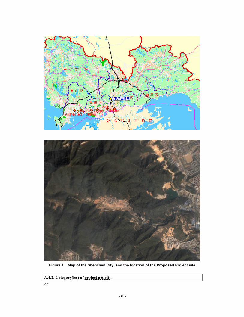
The Proposed Project is sited within the Xiaping Landfill in the Qingshuihe River area in
Luohu District, Shenzhen City of Guangdong province in south China. The geographical
coordinates of the Xiaping Landfill is east longitude 113°34′ and north latitude 22°29′. It is in
a northwest to southeast valley, 2km west to the Buji town, 2km north to the Shenzhen
Institute of Physical Education and 1km northeast to the Yinhu Tourist Centre. It can be
reached by car through Baojie Road which has been constructed specially for the
transportation of the Xiaping Landfill and is connected to the Honggang road and Shenping
arterial roads directly.
Figure 1 is a map showing the physical location of the Proposed Project site.
- 6 -
Figure 1. Map of the Shenzhen City, and the location of the Proposed Project site
A.4.2. Category(ies) of project activity:
>>

- 7 -
The Proposed Project would fall within sectoral scope 13: Waste handling and disposal.
A.4.3. Technology to be employed by the project activity:
>>
The Proposed Project includes three parts as LFG collection system, LFG utilization system
(LFG upgrade to CPLG and LFG power plant) and LFG flaring system.
LFG Collection System:
Vertical shaft was used to collect the LFG upwards. Compare to horizontal shaft collection
method, vertical shaft collection method is widely used in landfills for its characteristics in
simple structure, high efficiency, low investment and better seal performance. Multi-hole
pipes are installed perpendicularly in the vertical shaft filled with size-grade distribution of
gravel stones to increase the adsorption area. Distance between vertical shafts is about
30~50m. Vertical shafts is fitted with collection pipe, valve and sampling pipe. LFG collected
by the vertical shafts is concentrated in the collecting main and then extracted with Root's
blower.
LFG collection system will contain all the necessary equipment for collection, metering,
measuring and adjusting of LFG. Vertical shafts are isolated from each other for better gas
collection. The valve on each shaft is adjusted about twice per week to maintain proper gas
flow from each section of waste. The adjustment will be made based on the results of oxygen
concentration in the gas determined using a portable oxygen analyzer.
LFG collection system will be fitted with manual and automatic control and check valves, a
flame arrestor, gas sampling ports, pressure and temperature indicators, filters, flow meters, a
PLC control system and continuous gas analyzers tat conform to the monitoring plan.
LFG utilization system (system of upgrading LFG to CPLG and LFG power plant):
CPLG is used as automobile fuel for several years in developed countries. Figure 2 shows the
technology process of the system upgrading LFG to CPLG. This system is composed of
pretreatment unit and production unit. LFG is compressed, condensate, multi-step filtrated
and dried with Al2O3 to remove particles, water, H2S and other foreign substance. Then, it is
flow into the production unit with stable flow rate and pressure. Methane and CO2 in the LFG
were separated by pressure swing adsorption (PSA) process in production unit. More than
92% of methane in LFG is absorbed in this system②. After shifting gasoline automobile to
bi-fuel automobile and constructing specific gas fueling station, CPLG can be used in waste
transportation to substitute certain amount of gasoline.
② Guaranteed by equipment supplier according to Purchase Agreement, detailed is available as DOE
required.

- 8 -
Internal-combustion engine is applied in the LFG power plant. The installed capacity of LFG
power plant will increase while considering the financial status. According to plan, the total
installed capacity of 8MW is to be achieved in 2013. The Project Owner is supposed to
supply electricity to Shenzhen Grid.
Figure 2. Technology process of the system upgrading LFG to CPLG
LFG flaring system:
LFG flaring system is directly connected to the LFG collection system and the system
upgrading LFG to CPLG. It is used to combust the excessive LFG. LFG flaring system is
composed of tower and flare equipment with continues igniter. Flaring capacity of each
combustion heads of the LFG flaring system is 30-2640 Nm3/h. Its combustion efficiency is
higher than 99%③.
A.4.4. Brief explanation of how the anthropogenic emissions of anthropogenic
greenhouse gas (GHGs) by sources are to be reduced by the proposed CDM project
activity, including why the emission reductions would not occur in the absence of the
Proposed Project activity, taking into account national and/or sectoral policies and
circumstances:
>>
The Proposed Project is based on three complementary activities, as follows:
� The collection and flaring of landfill gas, thus converting its methane content into CO2,
reducing its greenhouse effect; and
� The upgrade and supply of CPLG as automobile fuel to the transportation vehicles of
the Xiaping Landfill, thus converting its methane content into CO2, reducing its
③ Guaranteed by equipment supplier according to Purchase Agreement, detailed is available as DOE
required.
- 9 -
greenhouse effect and not claim emission reduction for displacing CPLG from other
sources.
� The LFG power generation to supply electricity to Shenzhen Grid, thus converting its
methane content into CO2 in internal-combustion engine, reducing its greenhouse effect
and claim emission reduction for the displaced grid electricity.
The baseline scenario is defined as the most likely future scenario in the absence of the proposed CDM project activity. Establishing the future scenario requires an analysis and comparison of possible future scenarios using a comparison methodology that is justified for the project circumstances. Based on this analysis (See section B below), the baseline scenario is the continued uncontrolled release of LFG to the atmosphere, similarly to most landfills in China. At present, there are no national or local regulations regarding the collection of LFG from landfills, few landfills with LFG collection and utilization system were set up to develop experience with the technology with government support or international assistance. None of these projects were financially attractive, so the activity did not happen in China. Although the government encourages landfills to sanitarily treat municipal waste, however, due to technical and economic barriers, the Chinese legislation does not require landfill operators to flare or recover LFG and the only requirement is passively to vent the LFG in order to avoid the risk of explosion. The Proposed Project requires high initial investment and maintenance cost. The Proposed Project has significant environmental benefit, however, based on the financial analysis (See section B3 below), the Proposed Project IRR is negative without carbon revenue; while IRR is significantly improved with carbon revenue of CDM that leading to attractive and feasible. Clearly, the Proposed Project is not the economically most attractive course of action and therefore is not part of the baseline scenario. It can be concluded that emission reductions resulted from the Proposed Project are additional to any that would occur in absence of the Proposed Project. Therefore, the Proposed Project fulfils the additionality rule of CDM.
A.4.4.1. Estimated amount of emission reductions over the chosen crediting period:
>>
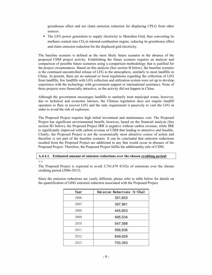
The Proposed Project is expected to avoid 5,741,878 tCO2e of emissions over the chosen crediting period (2006-2015). Since the emission reductions are yearly different, please refer to table below for details on the quantification of GHG emission reduction associated with the Proposed Project.
YearYearYearYear Emission Reductions Emission Reductions Emission Reductions Emission Reductions (t(t(t(t----COCOCOCO2222e)e)e)e)
2006 351,653 2007 397,961 2008 445,803 2009 495,534 2010 547,588 2011 598,836 2012 649,629 2013 700,393

- 10 -
2014 751,440 2015 803,041
TotalTotalTotalTotal (t(t(t(t----COCOCOCO2222e)e)e)e) 5,741,878 5,741,878 5,741,878 5,741,878
A.4.5. Public funding of the project activity:
>>
No public funding from Annex I countries is involved in the Proposed Project.

- 11 -
SECTION B. Application of a baseline methodology
B.1. Title and reference of the approved baseline methodology applied to the project
activity:
>>
ACM0001--“Consolidated baseline methodology for landfill gas project activities”. This
consolidated baseline methodology is based on elements from AM0002, AM0003, AM0010,
AM0011. For more information regarding the methodology please refer to
http://cdm.unfccc.int/methodologies/approved.
B.1.1. Justification of the choice of the methodology and why it is applicable to the
project activity:
>>
The methodology ACM0001 is applicable to landfill gas capture project activities, where the
baseline scenario is the partial or total atmospheric release of the gas and the project activities
include situations as:
a) The captured gas is flared; or
b) The captured gas is used to produce energy (e.g. electricity/thermal energy), but no
emission reductions are claimed for displacing or avoiding energy from other sources; or
c) The captured gas is used to produce energy (e.g. electricity/thermal energy), and emission
reductions are claimed for displacing or avoiding energy generation from other sources.
As previously described, the Proposed Project is based on three complementary activities, as
follows:
� The collection and flaring of landfill gas, thus converting its methane content into CO2,
reducing its greenhouse effect; and
� The upgrade and supply of CPLG as automobile fuel to the transportation vehicles of
the Xiaping Landfill, thus converting its methane content into CO2, reducing its
greenhouse effect and not claim emission reduction for displacing CPLG from other
sources.
� The LFG power generation to supply electricity to Shenzhen Grid and claim emission
reduction for displacing grid electricity, in converting its methane content into CO2 in
internal-combustion engine, reducing its greenhouse effect.
The project therefore fulfils the conditions of Option a), b) and c) (i.e. the captured land fill
gas is directly flared or used to produce energy and part of the credits from displacing grid
electricity is claimed) so that ACM0001 baseline methodology is considered the most
appropriate methodology for the Proposed Project.
According to the investigation on the treatment of LFG in landfills, in the absence of the
Proposed Project, the alternative baseline scenarios include:
Alternative 1: The landfill operator would continue the current business as usual practice of
not collecting and flaring LFG from the waste management operations.

- 12 -
Alternative 2: The landfill operator would invest in a LFG collection system as well as a
flaring system.
Alternative 3: The landfill operator would invest in a LFG collection system as well as a
flaring system and a production system (to produce electricity, thermal energy or LFG
upgraded CPLG).
The scenario that most likely occurs among the three alternative scenarios is analyzed as
follows:
For Alternative 1, the landfill operator is not required to take any action and the cost is zero.
Refer to the National Action Plan for Collection and Utilization of Landfill Gas (12/2001) ,
the Technical Code for Sanitary Landfill of Municipal Domestic Refuse (CJJ17-2001), and
the Standard for Pollution Control on the Landfill Site for Domestic Waste (GB16889-1997),
the Chinese legislation does not require landfill operators to flare or collect LFG. The only
requirement is to passively vent the LFG in order to avoid the risk of explosion. Moreover,
most landfills are far from residential areas and farms, the uncontrolled release of lower
concentrated methane will not give rise to public concern on health. Therefore, Alternative 1
is a plausible alternative for landfill operator.
Alternative 2 requires the landfill operator to invest in construction and operation of LFG
collection and flaring systems, which will cost hundreds of thousands of US$ without any
revenue. Without mandatory regulations on construction and operation of LFG collection and
flaring system and related penalties, without certain amount of financial support, there is no
incentive for the landfill operator to do so. Therefore Alternative 2 is not a plausible
alternative for landfill operator at present.
Compare to Alternative 2, there is a production system in Alternative 3 which will generate
revenue. Currently, possible LFG utilization technology options in China are mainly LFG
power generation, thermal energy supply or upgrade to CPLG. Application of each of these
technologies means an initial investment of millions of US$. Based on cost-benefit analysis of
these three technologies without any financial support, incentive policies or subsidy, IRR for
each technology is negative. Alternative 3 is not economically attractive for landfill operator
and not plausible.
In conclusion, the practical and feasible baseline scenario is the Alterative 1, the landfill
operator continues the current business as usual practice of not collecting and flaring landfill
gas from the waste management operations.
B.2. Description of how the methodology is applied in the context of the project
activity:
>>
The methodology will be applied for Option a), b) and c) of the Consolidated Methodology
ACM0001, where the captured land fill gas is directly flared or used to produce energy and
claim for part of the credits from displacing electricity from grid.

- 13 -
Specifically, the emission reduction will be calculated as follows:
( ) ythermalyyyelectricityCHyregyprojecty CEFETCEFEGGWPMDMDER ,,4,, ∗+∗+∗−= (1)
The above equation is that of the Consolidated Methodology for Landfill Project ACM0001,
where:
yER : GHG emission reduction achieved by the project activity during a given
year “y” (tCO2e);
yprojectMD , : Amount of methane actually destroyed/combusted during the year “y”
(tCH4);
yregMD , : Amount of methane that would have been destroyed/combusted during the
year “y” in the absence of the Proposed Project activity (tCH4);
4CHGWP : Approved Global Warming Potential value for methane (21tCO2e/t CH4);
yEG : Net quantity of electricity displaced during the year “y” (MWh);
yyelectricitCEF , : CO2 emissions intensity of the electricity displaced during the year “y”
(tCO2e/MWh);
yET : Quantity of thermal energy displaced during the year “y” (TJ);
ythermalCEF , : CO2 emissions intensity of the thermal energy displaced during the year “y”
(tCO2e/TJ).
As the Proposed Project doesn’t conclude thermal production, the emission reduction of the
Proposed Project will be calculated as follows:
( ) yyelectricityCHyregyprojecty CEFEGGWPMDMDER ,4,, ∗+∗−= (2)
The electricity generated from the Proposed Project is supply to Shenzhen Grid and the
electricity demand of the Proposed Project is supplied by the Shenzhen Grid. Shenzhen Grid
is part of Guangdong Grid. The total planned installed capacity of the Proposed Project is
about 8MW, and total capacity of all power consumers in the power generation system is no
more than 2MW, both of them are lower than 15MW, therefore the carbon emission factor
yyelectricitCEF , for the grid will be calculated according to the formulae for small scale
electricity CDM project (Methodology for Small Scale Activities Type I.D.-Renewable
Electricity Generation for a Grid), as shown below. Considering data availability, the carbon
emission factor ( yyelectricitCEF , ) uses the weighted average emissions of the current generation

- 14 -
mix, using following equations:
∑
∑ ∗=
j yj
ji jiyji
yyelectricitGEN
COEFFCEF
,
, ,,,
, (3)
Where:
yjiF ,, : is the amount of fuel i (in GJ) consumed by power sources j in year y;
j : is the power sources delivering electricity to the grid;
jiCOEF , : is the carbon coefficient of fuel i (tCO2/GJ);
yjGEN , : is the electricity (MWh) delivered to the grid by source j.
The data used for calculation of the weighted average emissions of Guangdong Grid is shown
in Annex 3. The main source of data is China Electric Power Yearbook and China Energy
Statistic Yearbook. The defaults used for calculation of calorific values for fuel types and fuel
oxidization came from the Revised IPCC Guidelines 1996 and Coal-Based Diversified Clean
Energy Strategy.
Since there is no regulatory or contractual requirements for landfill operator to specify
yregMD , , an “Adjustment Factor” ( AF ) is used to consider the amount of methane destroyed
in the baseline scenario as follows:
AFMDMD yprojectyreg ∗= ,, (4)
Although project owner should provide an ex ante estimate of emissions reductions, by
projecting the future GHG emissions of the landfill. Ex ante emission estimates may have an
influence on yregMD , . yprojectMD , will be determined ex post by metering the actual quantity
of methane captured and destroyed once the project activity is operational.
The amount of methane actually destroyed/combusted during the year “y” ( yprojectMD , ) is
estimated as follows:
FEEFfQMD erreerreyyproject ⋅⋅⋅= covcov, (5)
Where:
yQ : is CH4 generated in year y (t);
erref cov : is the fraction of area covered by the operational collection system;
erreEF cov : is the collection efficiency;
- 15 -
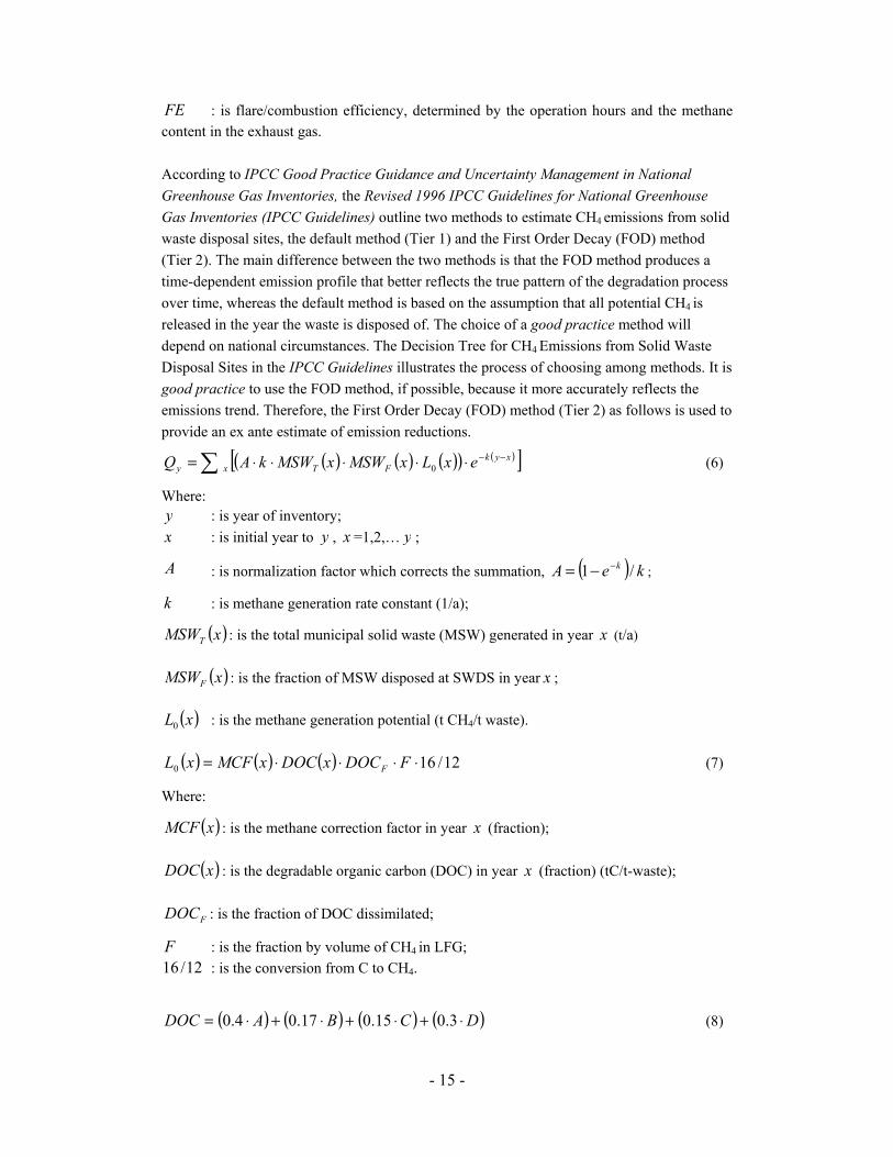
FE : is flare/combustion efficiency, determined by the operation hours and the methane
content in the exhaust gas.
According to IPCC Good Practice Guidance and Uncertainty Management in National
Greenhouse Gas Inventories, the Revised 1996 IPCC Guidelines for National Greenhouse
Gas Inventories (IPCC Guidelines) outline two methods to estimate CH4 emissions from solid
waste disposal sites, the default method (Tier 1) and the First Order Decay (FOD) method
(Tier 2). The main difference between the two methods is that the FOD method produces a
time-dependent emission profile that better reflects the true pattern of the degradation process
over time, whereas the default method is based on the assumption that all potential CH4 is
released in the year the waste is disposed of. The choice of a good practice method will
depend on national circumstances. The Decision Tree for CH4 Emissions from Solid Waste
Disposal Sites in the IPCC Guidelines illustrates the process of choosing among methods. It is
good practice to use the FOD method, if possible, because it more accurately reflects the
emissions trend. Therefore, the First Order Decay (FOD) method (Tier 2) as follows is used to
provide an ex ante estimate of emission reductions.
( ) ( ) ( )( ) ( )[ ]∑−−
⋅⋅⋅⋅⋅=xyk
FTxy exLxMSWxMSWkAQ 0 (6)
Where:
y : is year of inventory;
x : is initial year to y , x =1,2,… y ;
A : is normalization factor which corrects the summation, ( ) keA k /1 −−= ;
k : is methane generation rate constant (1/a);
( )xMSWT : is the total municipal solid waste (MSW) generated in year x (t/a)
( )xMSWF : is the fraction of MSW disposed at SWDS in year x ;
( )xL0 : is the methane generation potential (t CH4/t waste).
( ) ( ) ( ) 12/160 ⋅⋅⋅⋅= FDOCxDOCxMCFxL F (7)
Where:
( )xMCF : is the methane correction factor in year x (fraction);
( )xDOC : is the degradable organic carbon (DOC) in year x (fraction) (tC/t-waste);
FDOC : is the fraction of DOC dissimilated;
F : is the fraction by volume of CH4 in LFG;
12/16 : is the conversion from C to CH4.
( ) ( ) ( ) ( )DCBADOC ⋅+⋅+⋅+⋅= 3.015.017.04.0 (8)

- 16 -
Where:
A : is the fraction of MSW that is paper and textiles;
B : is the fraction of MSW that is garden waste, park waste or other non-food organic
putrescibles;
C : is the fraction of MSW that is food waste;
D : is the fraction of MSW that is wood or straw.
B.3. Description of how the anthropogenic emissions of GHG by sources are reduced
below those that would have occurred in the absence of the registered CDM project
activity:
>>
The additionality analysis of project scenario is done by using the Consolidated Tool for
demonstration of additionality, which follows the following steps:
Step 0: Preliminary screening of projects based on the starting date of the project
activity
The starting date of the Proposed Project is May 2005, when feasibility study report for the
LFG collection and utilization system was finalized. The Proposed Project is not that type of
project starting before the date of the first CDM project registered and prior to the start of the
crediting period. CDM finance was considered from the beginning and the project owner has
signed a legally-binding agreement on CDM project development with Beijing Sower
Technology Development Co., Ltd in March 2005. (Available on DOE/DNA request.)
Step 1: Identification of alternative to the project activity consist with current laws and
regulations
The objective of the Step 1 is to define realistic and credible alternatives to the project
activity(s) that can be (part of) the baseline scenario through the following sub-steps:
Sub-step 1a. Define alternatives to the project activity
Plausible and credible alternatives available to the Proposed Project include:
Alternative 1: The landfill operator could continue the current business as usual practice of
not collecting and flaring LFG from the waste management operations.
Alternative 2: The landfill operator would invest in a LFG collection system as well as a
flaring system.
Alternative 3: The landfill operator would invest in a LFG collection system as well as a
flaring system and a production system (to produce electricity, thermal energy or LFG
upgraded CPLG).
Sub-step 1b. Enforcement of applicable laws and regulations
In the section B.1.1, the three alternatives to the Proposed Project activity are discussed in
details with the conclusion that only Alternative 1 is the plausible alternative to the Proposed
Project activity that can be the baseline scenario.

- 17 -
Refer to the National Action Plan for Collection and Utilization of Landfill Gas (12/2001),
the national code of Technical Code for Sanitary Landfill of Municipal Domestic Refuse
(CJJ17-2001), and the Standard for Pollution Control on the Landfill Site for Domestic Waste
(GB16889-1997), current priorities of the authorities are to prevent illegal dumping and to
improve the conditions at “controlled” sites, which apply lower standards. Considering the
great technical and economic barriers to upgrade existing landfills, it is unlikely to introduce
mandatory LFG collection and utilization regulations in the foreseeable future.
As described above, the Proposed Project is not baseline scenario. Baseline scenario for the
Proposed Project is Alternative 1: the landfill operator could continue the current business as
usual practice of not collecting and flaring LFG from the waste management operations.
Step 2: Investment analysis
The purpose of this step is to determine whether the Proposed Project activity is economically
or financially less attractive than other alternatives without the revenue from the sale of
certified emission reductions (CERs). The investment analysis was done in the following
steps:
Sub-step 2a. Determine appropriate analysis method
Tools for the demonstration and assessment of additionality suggests three analysis methods:
simple cost analysis (option I), investment comparison analysis (option II) and benchmark
analysis (option III).
Since the Proposed Project not only obtains CDM revenue but also revenue through sales of
upgraded LFG, simple cost analysis method (option I) is not appropriate. Investment
comparison analysis method (option II) is applicable to projects whose alternatives are similar
investment projects. Only on such basis, comparison analysis can be conducted. The
alternative baseline scenario of the Proposed Project is to continue the current business as
usual practice rather than new investment projects. Therefore option II is not an appropriate
method too. The Proposed Project will use benchmark analysis method based on the
consideration that benchmark IRR and equity IRR of the Proposed Project and the business as
usual practice are available to investors in the country.
Sub-step 2b. Benchmark Analysis Method (Option III)
The likelihood of development of the Proposed Project, as opposed to the continuation of
current activities (i.e. no collection and flaring of LFG) will be determined by comparing its
IRR with the benchmark of interest rate available to a local investor. In May 2005, interest
rates for a five-year term of local banks in China are 3.6% for saving and 5.85% for loan.
The interest rate for government bonds is up to 4.5%. The average returns from stock
market and private equity funds are higher, which are about 11% and 13%, respectively.
Since the Proposed Project is an environmental protection project implemented by a private
company, 12% is taken as financial benchmark rate of return (after tax).
- 18 -
Sub-step 2c. Calculation and comparison of financial indicators
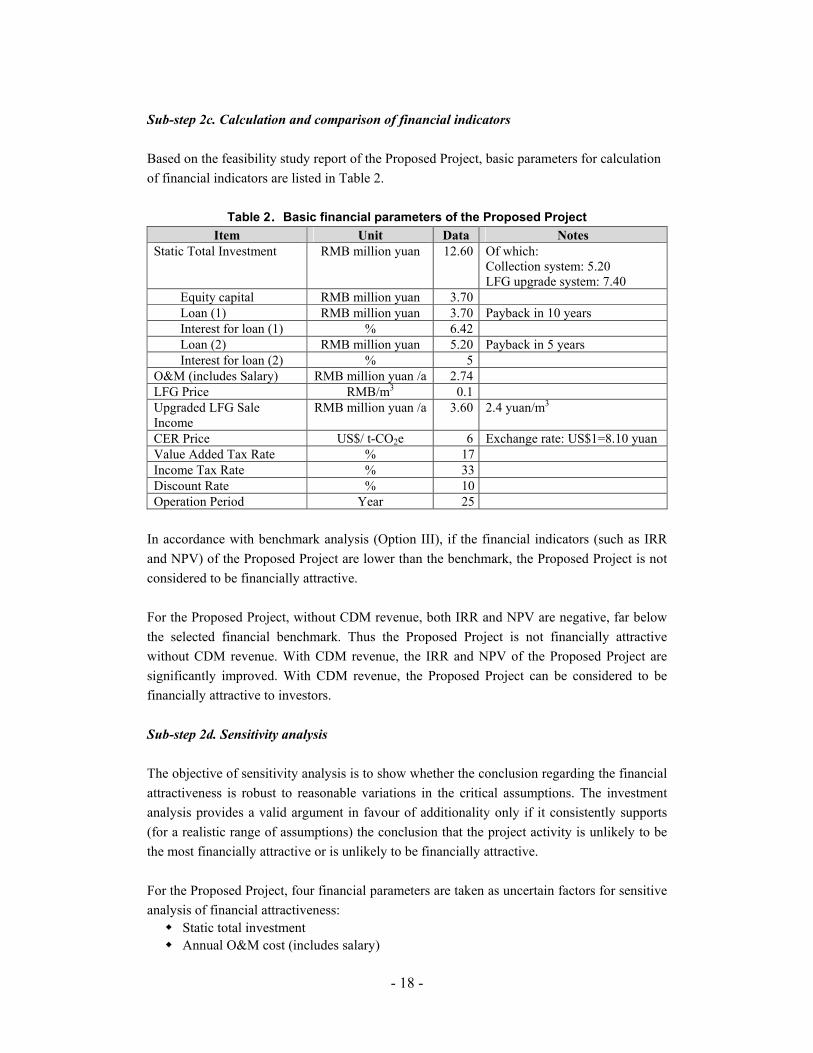
Based on the feasibility study report of the Proposed Project, basic parameters for calculation
of financial indicators are listed in Table 2.
Table 2....Basic financial parameters of the Proposed Project
Item Unit Data Notes
Static Total Investment RMB million yuan 12.60 Of which: Collection system: 5.20 LFG upgrade system: 7.40
Equity capital RMB million yuan 3.70
Loan (1) RMB million yuan 3.70 Payback in 10 years
Interest for loan (1) % 6.42
Loan (2) RMB million yuan 5.20 Payback in 5 years
Interest for loan (2) % 5
O&M (includes Salary) RMB million yuan /a 2.74
LFG Price RMB/m3 0.1
Upgraded LFG Sale Income
RMB million yuan /a 3.60 2.4 yuan/m3
CER Price US$/ t-CO2e 6 Exchange rate: US$1=8.10 yuan
Value Added Tax Rate % 17
Income Tax Rate % 33
Discount Rate % 10
Operation Period Year 25
In accordance with benchmark analysis (Option III), if the financial indicators (such as IRR
and NPV) of the Proposed Project are lower than the benchmark, the Proposed Project is not
considered to be financially attractive.
For the Proposed Project, without CDM revenue, both IRR and NPV are negative, far below
the selected financial benchmark. Thus the Proposed Project is not financially attractive
without CDM revenue. With CDM revenue, the IRR and NPV of the Proposed Project are
significantly improved. With CDM revenue, the Proposed Project can be considered to be
financially attractive to investors.
Sub-step 2d. Sensitivity analysis
The objective of sensitivity analysis is to show whether the conclusion regarding the financial
attractiveness is robust to reasonable variations in the critical assumptions. The investment
analysis provides a valid argument in favour of additionality only if it consistently supports
(for a realistic range of assumptions) the conclusion that the project activity is unlikely to be
the most financially attractive or is unlikely to be financially attractive.
For the Proposed Project, four financial parameters are taken as uncertain factors for sensitive
analysis of financial attractiveness:
� Static total investment
� Annual O&M cost (includes salary)

- 19 -
� Upgraded LFG sale income
These parameters were selected as the most likely to fluctuate over time. Financial analyses
are performed altering each of these parameters within the range of -10% to +10%. Though
IRR of total investment of the Proposed Project varies to different extent, it keeps negative.
To achieve IRR=12% without CDM revenue, it requires to remove all O&M cost (includes
salary) or increase the upgraded LFG sale income by 100%. To keep normal operation of the
project, it is impossible to remove all O&M cost (includes salary). The calculated price of
CPLG is 2.4 yuan/m3, equal to CNG price in the market, there is no space for the LFG sale
income to increase much. Therefore the project activity is unlikely to be financially attractive
without CDM revenue.
Step 3. Barrier analysis
This step is used to determine whether the Proposed Project activity faces real barriers that:
1) Prevent the implementation of this type of Proposed Project activity; and
2) Do not prevent the implementation of at least one of the alternatives.
Step 3 uses the following sub-steps:
Sub-step 3a. Identify barriers that would prevent the implementation of type of the
Proposed Project activity
Establish that there are barriers that would prevent the implementation of the type of Proposed
Project activity from being carried out if the Proposed Project activity was not registered as a
CDM activity. These barriers include:
(1) Investment barriers
Investment of the technologies adopted by the Proposed Project is much higher. Since gas
fuel has not widely used in Shenzhen city and the consumer has limited understanding of
CPLG, CPLG also faces market barrier. Without CDM revenue, IRR of the Proposed Project
is lower than benchmark IRR. In this case, the Proposed Project is not likely to attract
commercial loan. Without the CDM revenue, it is difficult for the Proposed Project owner to
achieve financial plan and the Proposed Project will face financing barriers. Only with the
CDM revenue can loan be repayment and attractive financial return for investors be ensured.
With CDM revenue, the Project Owner could speed up investment return, demonstrate CPLG
as automobile fuel thus to promote construction and operation of larger scale of LFG
utilization facilities in Xiaping Landfill.
(2) Technology barriers
Technological risk is associated with the adoption of the LFG upgrade to CPLG system which
is technically advanced and for the first time to be commercially applied in China. Although
the technology has been approved feasible and the project owner has got technology support
from Department of Environmental Science and Engineering of Tsinghua University, the
application of this technology still faces the risk resulted from the lack of skilled and/or

- 20 -
properly trained staff to operate and maintain the technology. Without CDM revenue, the
project owner is lack of training and maintenance fund thus no incentive to implement the
advanced technology. To continue current LFG uncontrolled release is the best option. Some
of the CDM revenue can be used as a reserve for the operation and maintenance of the LFG
upgraded to CPLG system and the training of staff, therefore enabling the project to overcome
the technological barriers and to be implemented smoothly.
Above identified barriers are common to LFG collection and utilization projects in China and
these are the main proof for demonstrating additionality.
Sub-step 3b. Show that the identified barriers would not prevent the implementation of at
least one of the alternatives (except the Proposed Project activity)
As mentioned in the section B.1.1 and Sub-step 1a, the three alternatives to the Proposed
Project activity are discussed in details with the conclusion that Alternative 1 is the only
plausible alternative to the Proposed Project activity that can be the baseline scenario, i.e. the
landfill operator could continue the current business as usual practice of not collecting and
flaring LFG from the waste management operations. Alternative 1 is in compliance with
Chinese laws and regulations, without any investment or technological barrier etc.
Step 4. Common practice analysis
With the growing population and improved living standard, China has recognized the need to
improve its waste management and has set a goal of disposing of 60% of municipal waste in
sanitary landfills by 2000.
With the increasing of organic content of the waste, methane emission from landfills has
become one of the fastest growing sectoral sources of GHG in China. The Ministry of
Construction developed a comprehensive technical standard on municipal solid waste
management in 1989. However, in general the standards were not followed due to investment
and technology barriers. To date there has been limited development of LFG collection and
utilization projects in China. For a quite large number of landfills, there exist problems such
as have inappropriate or no cover system, limited or no compaction, no gas control system,
etc④.
China legislation does not require landfills to recover, utilize or dispose LFG. The municipal
waste is disposed by using the technology of traditional landfills, without consideration of
collection and utilization of LFG⑤. So far, very few landfills have been designed to collect
and utilize (or even) flare the main body of LFG generated. Most of which are demonstration
projects funded by development assistance resources. The Nanjing Tianjingwa LFG
Electricity Project and Meizhou Landfills Gas Recovery and Utilization as Energy Project
approved by China DNA have provided detail description on the importance of CDM revenue
for certain type of projects.
④ Source: Environmental Resource Management 2004, China Waste Management Working Paper ⑤ Source: National Action Plan for Collection and Utilization of LFG (12/2001)
- 21 -
Step 5. Impact of CDM Registration
The Proposed Project has not been put into operation. As shown in Step 2 above, in the
absence of anticipated CDM revenue, the project owner is unlikely to move forward the
Proposed Project in order to cut down investment losses. By taking this into account, the
proposed project owner, Shenzhen Lisai Development Co., Ltd, has agreed to cooperate with
Beijing Sower Technology Development Co., Ltd. for CDM project development. The
cooperative agreement was signed in March 2005.
If the proposed project could be successfully registered at the EB, the CER sales revenue
would supplement the sales income to gain investment return higher than that of the baseline
scenario. The proposed project is the first project equipped with advanced LFG upgraded to
CPLG system in China. The CDM revenues can be one of the sources for the technical
maintenance and staff training reserve for the LFG upgraded to CPLG system that help the
proposed project owner to mitigate financial risks, reduce technological risks so as to
guarantee the reliable operation of the project and promote LFG utilization in Xiaping
Landfill.
Conclusion
To summarize, it can be proved that the proposed project activity is not (part of) baseline
scenario. Without support from CDM, the proposed project scenario would not occur. Instead,
the landfill operator could continue the current business as usual practice of not collecting and
flaring LFG from the waste management operations. As described in Step 2 and Step 3, the
Proposed Project has strong additionality and can reduce the GHG emission. If the proposed
project fails to be registered as a CDM project, this portion of emission reduction can not be
realized. Based on the above analysis, it can be proved that the proposed project meets the
additionality in the aspect of environment, investment and technology. The additionality
analysis provides essential evidence that, the CDM revenue can enable the proposed project to
overcome the barriers faced by LFG collection and utilization projects in China.
B.4. Description of how the definition of the project boundary related to the baseline
methodology selected is applied to the project activity:
The project boundary shall encompass all anthropogenic emissions by sources of GHG under
the control of the project participants that are significant and reasonably attributable to the
CDM project activity. According to ACM0001 baseline methodology, the project boundary is
the site of the project activity where the LFG will be captured and destroyed/used.
The following project activities and emission sources are considered within the project
boundaries:
� CH4 colleted from the landfill site. Considering that 10% of the site is still under filling,
it is estimated that only 80% of the collection system is operated in average
conservatively. With 60% collection efficiency of the collection system, 48% of LFG
generated in the site will be captured.
� CH4 emission from the automobile engines.
- 22 -
� CO2 emission from the combustion of LFG in the flares and automobile engines. When
combusted, methane is converted into CO2. As the methane is organic in nature, the
CO2 released during the combustion process was originally fixed via biomass so that
these emissions are not counted as project emissions. The life cycle CO2 emissions of
LFG are zero.
� CO2 emission of the grid electricity for operation of the project activity.
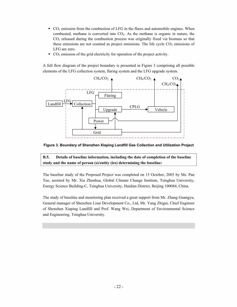
A full flow diagram of the project boundary is presented in Figure 3 comprising all possible
elements of the LFG collection system, flaring system and the LFG upgrade system.
Figure 3. Boundary of Shenzhen Xiaping Landfill Gas Collection and Utilization Project
B.5. Details of baseline information, including the date of completion of the baseline
study and the name of person (s)/entity (ies) determining the baseline:
The baseline study of the Proposed Project was completed on 15 October, 2005 by Ms. Pan
Tao, assisted by Mr. Xia Zhenhua, Global Climate Change Institute, Tsinghua University,
Energy Science Building-C, Tsinghua University, Haidian District, Beijing 100084, China.
The study of baseline and monitoring plan received a great support from Mr. Zhang Guangyu,
General manager of Shenzhen Lisai Development Co., Ltd, Mr. Yang Zhigui, Chief Engineer
of Shenzhen Xiaping Landfill and Prof. Wang Wei, Department of Environmental Science
and Engineering, Tsinghua University.
CH4/CO2
Grid
Power
Flaring
Upgrade Vehicle
Landfill Collection LFG
LFG
CH4/CO2
CO2 CH4/CO2
CPLG
- 23 -
SECTION C. Duration of the project activity / Crediting period
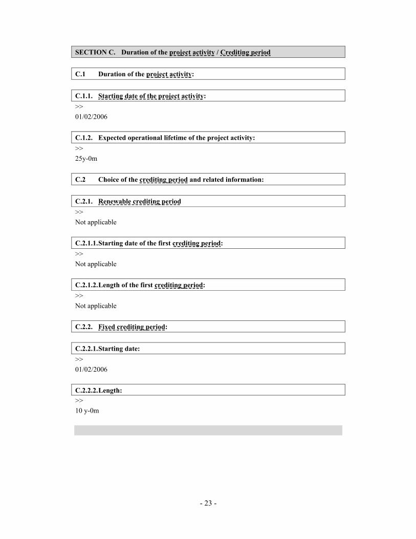
C.1 Duration of the project activity:
C.1.1. Starting date of the project activity:
>>
01/02/2006
C.1.2. Expected operational lifetime of the project activity:
>>
25y-0m
C.2 Choice of the crediting period and related information:
C.2.1. Renewable crediting period
>>
Not applicable
C.2.1.1. Starting date of the first crediting period:
>>
Not applicable
C.2.1.2. Length of the first crediting period:
>>
Not applicable
C.2.2. Fixed crediting period:
C.2.2.1. Starting date:
>>
01/02/2006
C.2.2.2. Length:
>>
10 y-0m

- 24 -
SECTION D. Application of a monitoring methodology and plan
D.1. Name and reference of approved monitoring methodology applied to the project
activity:
ACM0001 “Consolidated monitor methodology for landfill gas project activities”. This
consolidated monitor methodology is based on elements from AM0002, AM0003, AM0010,
AM0011. For more information regarding the methodology please refer to
http://cdm.unfccc.int/methodologies/approved.
D.2. Justification of the choice of the methodology and why it is applicable to the
project activity:
The approved ACM0001 monitoring methodology shall be used in conjunction with the
approved ACM0001 baseline methodology, which has been adopted by the Proposed Project.
The methodology ACM0001 is applicable to landfill gas capture project activities, where the
baseline scenario is the partial or total atmospheric release of the gas and the project activities
include situations as:
a) The captured gas is flared; or
b) The captured gas is used to produce energy (e.g. electricity/thermal energy), but no
emission reductions are claimed for displacing or avoiding energy from other sources; or
c) The captured gas is used to produce energy (e.g. electricity/thermal energy), and emission
reductions are claimed for displacing or avoiding energy generation from other sources.
As previously described, the Proposed Project is based on three complementary activities, as
follows:
� The collection and flaring of landfill gas, thus converting its methane content into CO2,
reducing its greenhouse effect; and
� The upgrade and supply of CPLG as automobile fuel to the transportation vehicles of
the Xiaping Landfill, thus converting its methane content into CO2, reducing its
greenhouse effect and not claim emission reduction for displacing CPLG from other
sources.
� The LFG power generation to supply electricity to Shenzhen Grid and claim emission
reduction for displacing grid electricity, in converting its methane content into CO2 in
internal-combustion engine, reducing its greenhouse effect.
The project therefore fulfils the conditions of Option a), b) and c) (i.e. the captured land fill
gas is directly flared or used to produce energy and part of the credits from displacing grid
electricity is claimed) so that ACM0001 monitoring methodology was considered the most
appropriate methodology for the Proposed Project.

- 25 -
In line with ACM0001 monitoring methodology, Option 2 is chosen as the monitoring
method.
PROJECT DESIGN DOCUMENT FORM (CDM PDD) - Version 02
CDM – Executive Board Page 26
This template shall not be altered. It shall be completed without modifying/adding headings or logo, format or font.
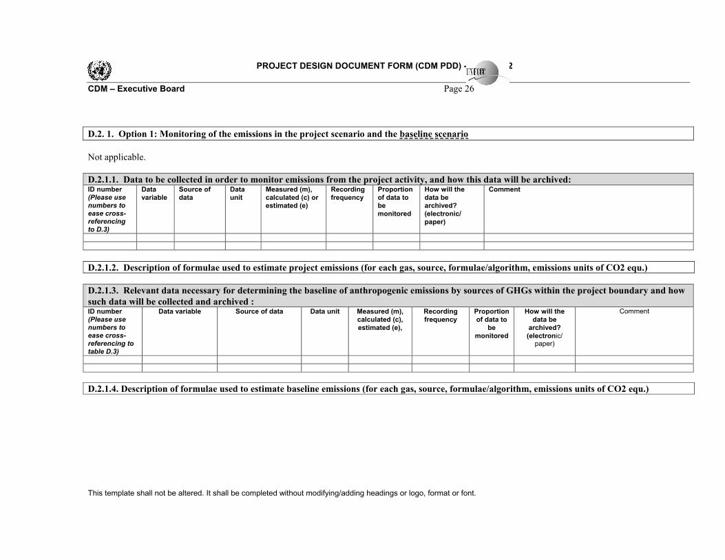
D.2. 1. Option 1: Monitoring of the emissions in the project scenario and the baseline scenario
Not applicable.
D.2.1.1. Data to be collected in order to monitor emissions from the project activity, and how this data will be archived: ID number (Please use numbers to ease cross-referencing to D.3)
Data
variable
Source of
data
Data
unit
Measured (m),
calculated (c) or
estimated (e)
Recording
frequency
Proportion
of data to
be
monitored
How will the
data be
archived?
(electronic/
paper)
Comment
D.2.1.2. Description of formulae used to estimate project emissions (for each gas, source, formulae/algorithm, emissions units of CO2 equ.)
D.2.1.3. Relevant data necessary for determining the baseline of anthropogenic emissions by sources of GHGs within the project boundary and how
such data will be collected and archived : ID number (Please use numbers to ease cross-referencing to table D.3)
Data variable Source of data Data unit Measured (m),
calculated (c),
estimated (e),
Recording
frequency
Proportion
of data to
be
monitored
How will the
data be
archived?
(electronic/ paper)
Comment
D.2.1.4. Description of formulae used to estimate baseline emissions (for each gas, source, formulae/algorithm, emissions units of CO2 equ.)

PROJECT DESIGN DOCUMENT FORM (CDM PDD) - Version 02
CDM – Executive Board Page 27
This template shall not be altered. It shall be completed without modifying/adding headings or logo, format or font.
D. 2.2. Option 2: Direct monitoring of emission reductions from the project activity (values should be consistent with those in section E).
D.2.2.1. Data to be collected in order to monitor emissions from the project activity, and how this data will be archived: ID number (Please use
numbers to ease cross-referencing to table D.3)
Data variable Source of data Data unit Measured
(m),
calculated
(c),
estimated
(e),
Recording
frequency
Proportion
of data to
be
monitored
How will the
data be
archived?
(electronic/
paper)
Comment
1. LFGtotal,y Total amount of LFG captured
Measured by flow meter
m3 m Continuously/periodically 100% electronic Data to be aggregated monthly and yearly.
2. LFGflare,y Amount of LFG flared
Measured by flow meter
m3 m Continuously/periodically 100% electronic Data to be aggregated monthly and yearly.
3. LFGupgrade,y Amount of LFG upgraded to automobile fuel
Measured by flow meter
m3 m Continuously/periodically 100% electronic Data to be aggregated monthly and yearly.
4. LFGelectricity,y Amount of LFG used in power generation
Measured by flow meter
m3 m Continuously/periodically 100% electronic
Data to be aggregated monthly and yearly.
5. FE Flare/combustion efficiency, determined by the operation hours (1) and the methane content in the exhaust gas (2)
Measured by gas quality analyzer
%
m
(1) Continuously (2) Quarterly, if unstable
n/a electronic (1) Periodic measurement of methane content of flare exhaust gas. (2) Continuous measurement of operation time of flare

PROJECT DESIGN DOCUMENT FORM (CDM PDD) - Version 02
CDM – Executive Board Page 28
This template shall not be altered. It shall be completed without modifying/adding headings or logo, format or font.
6. wCH4,y Methane fraction in the LFG
Measured by gas quality analyzer
m³CH4 /m³LFG m Continuously/periodically 100% electronic Calculated with daily average
7. T Temperature of LFG
Measured by online temperature sensor
°C m Continuously/periodically 100% electronic Measured to determine the density of methane DCH4.
8. P Pressure of LFG Measured by online pressure sensor
Pa m Continuously/periodically 100% electronic Measured to determine the density of methane DCH4.
9. EGy Net electricity supplied to grid
Measured by ammeter
MWh m Continuously 100% electronic Deduct power consumption. Required to determine CO2 emission from use of electricity to operate the project activity
10. CEFelectiricity,y CO2 emission factor of the electricity in ID 8
Calculated based on data from China Electric Power Yearbook.
tCO2 /MWh c annually 100% electronic Required to determine CO2 emission from use of electricity to operate the project activity
11 Regulatory requirements relating to LFG projects
www.es.org.cn
www.szepb.gov.cn Test n/a annually 100% electronic Required for
any changes to the adjustment factor (AF) or directly MDreg,y
D.2.2.2. Description of formulae used to calculate project emissions (for each gas, source, formulae/algorithm, emissions units of CO2 equ.):

PROJECT DESIGN DOCUMENT FORM (CDM PDD) - Version 02
CDM – Executive Board Page 29
This template shall not be altered. It shall be completed without modifying/adding headings or logo, format or font.
The source of emission from the Proposed Project is the combustion of LFG in the flares and in the automobile engines. Methane is converted into CO2 when combusted. As methane is organic in nature these emissions are not counted as project emissions. The CO2 released during the combustion process was originally fixed via biomass so that the life cycle CO2 emission of LFG is zero. The project, however, does not collect all the methane that is generated. Consequently, these emissions are excluded from the projections of emission reduction expected from the project. Furthermore, given that the emission reductions from this type of project are measured directly, there is no need to monitor project emission.
D.2.3. Treatment of leakage in the monitoring plan
D.2.3.1. If applicable, please describe the data and information that will be collected in order to monitor leakage effects of the project activity ID number (Please use numbers to ease cross-referencing to table D.3)
Data variable
Source of data Data
unit
Measured (m), calculated (c) or estimated (e)
Recording frequency
Proportion of data to be monitored
How will the data be archived? (electronic/ paper)
Comment
The leakage of the Proposed Project is the emission of CPLG conbustion during transportation. Experiment shows that emission of bi-fuel automobile is equivalent to emission of gasoline automobile under similar conditions with less CO2 and more HC. However given the HC emission is restricted according to Euro III requirement, the total emission of HC must be less than 0.2 g/km. There are about 200 automobiles in Xiaping Landfill, average running Kilometer Per Vehicle Per Day is 150 km, the total HC emission is about 2.19 tons, equivalent to 45.99 tCO2e per year. Compare to the emission reductions of the Proposed Project, this leakage could be neglected.
D.2.3.2. Description of formulae used to estimate leakage (for each gas, source, formulae/algorithm, emissions units of CO2 equ.)
As described above, the Proposed Project can take no account of leakage, 0=yL .
D.2.4. Description of formulae used to estimate emission reductions for the project activity (for each gas, source, formulae/algorithm, emissions units
of CO2 equ.)
( ) ythermalyyyelectricityCHyregyprojecty CEFETCEFEGGWPMDMDER ,,4,, ∗+∗+∗−= (1)
The above equation is that in the Consolidated Methodology for Landfill Project ACM0001, where:
PROJECT DESIGN DOCUMENT FORM (CDM PDD) - Version 02
CDM – Executive Board Page 30
This template shall not be altered. It shall be completed without modifying/adding headings or logo, format or font.
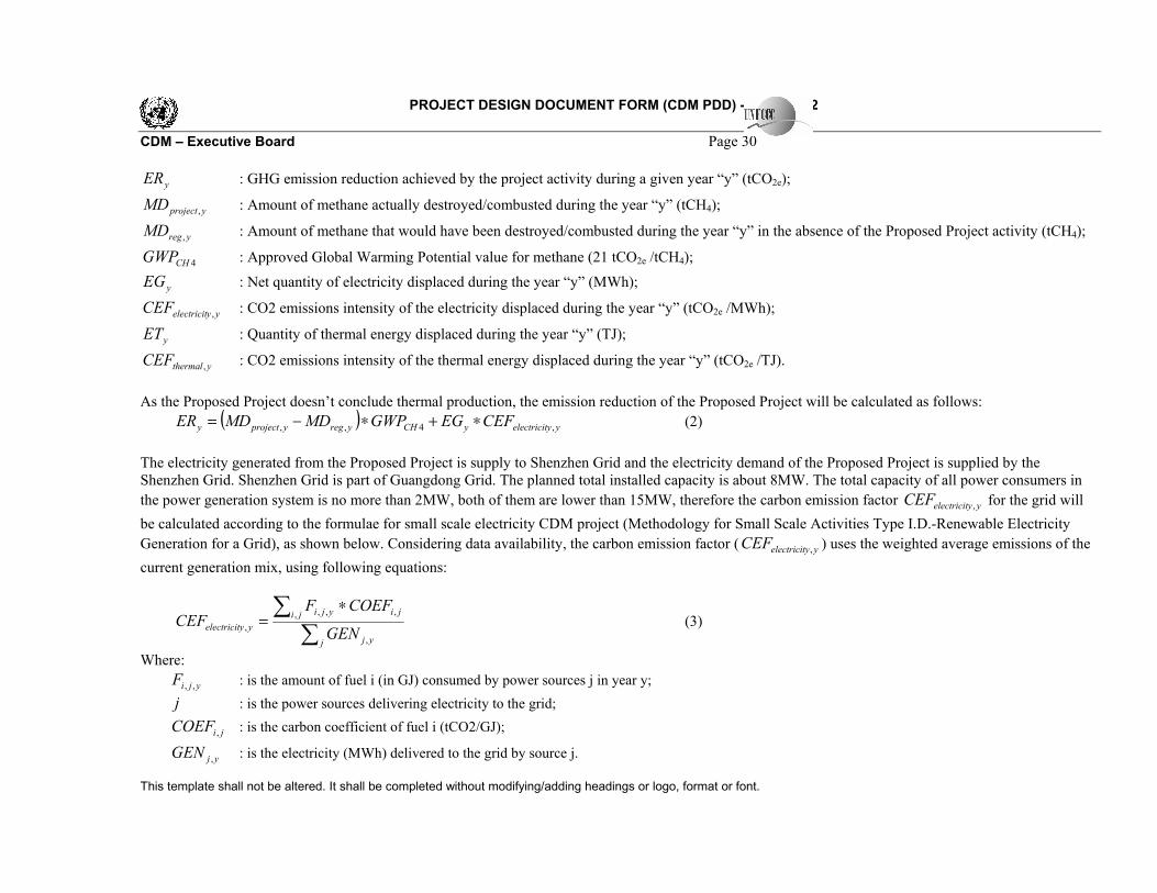
yER : GHG emission reduction achieved by the project activity during a given year “y” (tCO2e);
yprojectMD , : Amount of methane actually destroyed/combusted during the year “y” (tCH4);
yregMD , : Amount of methane that would have been destroyed/combusted during the year “y” in the absence of the Proposed Project activity (tCH4);
4CHGWP : Approved Global Warming Potential value for methane (21 tCO2e /tCH4);
yEG : Net quantity of electricity displaced during the year “y” (MWh);
yyelectricitCEF , : CO2 emissions intensity of the electricity displaced during the year “y” (tCO2e /MWh);
yET : Quantity of thermal energy displaced during the year “y” (TJ);
ythermalCEF , : CO2 emissions intensity of the thermal energy displaced during the year “y” (tCO2e /TJ).
As the Proposed Project doesn’t conclude thermal production, the emission reduction of the Proposed Project will be calculated as follows:
( ) yyelectricityCHyregyprojecty CEFEGGWPMDMDER ,4,, ∗+∗−= (2)
The electricity generated from the Proposed Project is supply to Shenzhen Grid and the electricity demand of the Proposed Project is supplied by the Shenzhen Grid. Shenzhen Grid is part of Guangdong Grid. The planned total installed capacity is about 8MW. The total capacity of all power consumers in
the power generation system is no more than 2MW, both of them are lower than 15MW, therefore the carbon emission factor yyelectricitCEF , for the grid will
be calculated according to the formulae for small scale electricity CDM project (Methodology for Small Scale Activities Type I.D.-Renewable Electricity
Generation for a Grid), as shown below. Considering data availability, the carbon emission factor ( yyelectricitCEF , ) uses the weighted average emissions of the
current generation mix, using following equations:
∑
∑ ∗=
j yj
ji jiyji
yyelectricitGEN
COEFFCEF
,
, ,,,
, (3)
Where:
yjiF ,, : is the amount of fuel i (in GJ) consumed by power sources j in year y;
j : is the power sources delivering electricity to the grid;
jiCOEF , : is the carbon coefficient of fuel i (tCO2/GJ);
yjGEN , : is the electricity (MWh) delivered to the grid by source j.
PROJECT DESIGN DOCUMENT FORM (CDM PDD) - Version 02
CDM – Executive Board Page 31
This template shall not be altered. It shall be completed without modifying/adding headings or logo, format or font.
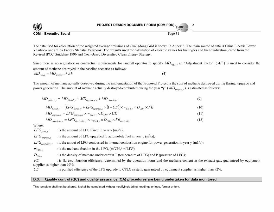
The data used for calculation of the weighted average emissions of Guangdong Grid is shown in Annex 3. The main source of data is China Electric Power Yearbook and China Energy Statistic Yearbook. The defaults used for calculation of calorific values for fuel types and fuel oxidization, came from the Revised IPCC Guideline 1996 and Coal-Based Diversified Clean Energy Strategy.
Since there is no regulatory or contractual requirements for landfill operator to specify yregMD , , an “Adjustment Factor” ( AF ) is used to consider the
amount of methane destroyed in the baseline scenario as follows:
AFMDMD yprojectyreg ∗= ,, (4)
The amount of methane actually destroyed during the implementation of the Proposed Project is the sum of methane destroyed during flaring, upgrade and
power generation. The amount of methane actually destroyed/combusted during the year “y” ( yprojectMD , ) is estimated as follows:
yelectricityupgradedyflaredyproject MDMDMDMD ++= ,,, (9)
( )( ) FEDwUELFGLFGMD CHyCHyupgradeyflaredyflared ×××−×+= 4,4,,, 1 (10)
UEDwLFGMD CHyCHyupgradeyupgrade ×××= 4,4,, (11)
yelectricitCHyCHyyelectricityyelectricit FEDwLFGMD ×××= 4,4,, (12)
Where:
yflareLFG , : is the amount of LFG flared in year y (m3/a);
yupgradeLFG , : is the amount of LFG upgraded to automobile fuel in year y (m3/a);
yyelectirictLFG , : is the amout of LFG combusted in internal combustion engine for power generation in year y (m3/a);
yCH ,4ω : is the methane fraction in the LFG, (m3CH4/ m3LFG);
4CHD : is the density of methane under certain T (temperature of LFG) and P (pressure of LFG);
FE : is flare/combustion efficiency, determined by the operation hours and the methane content in the exhaust gas, guaranteed by equipment supplier as higher than 99%;
UE : is purified efficiency of the LFG upgrade to CPLG system, guaranteed by equipment supplier as higher than 92%.
D.3. Quality control (QC) and quality assurance (QA) procedures are being undertaken for data monitored
PROJECT DESIGN DOCUMENT FORM (CDM PDD) - Version 02
CDM – Executive Board Page 32
This template shall not be altered. It shall be completed without modifying/adding headings or logo, format or font.
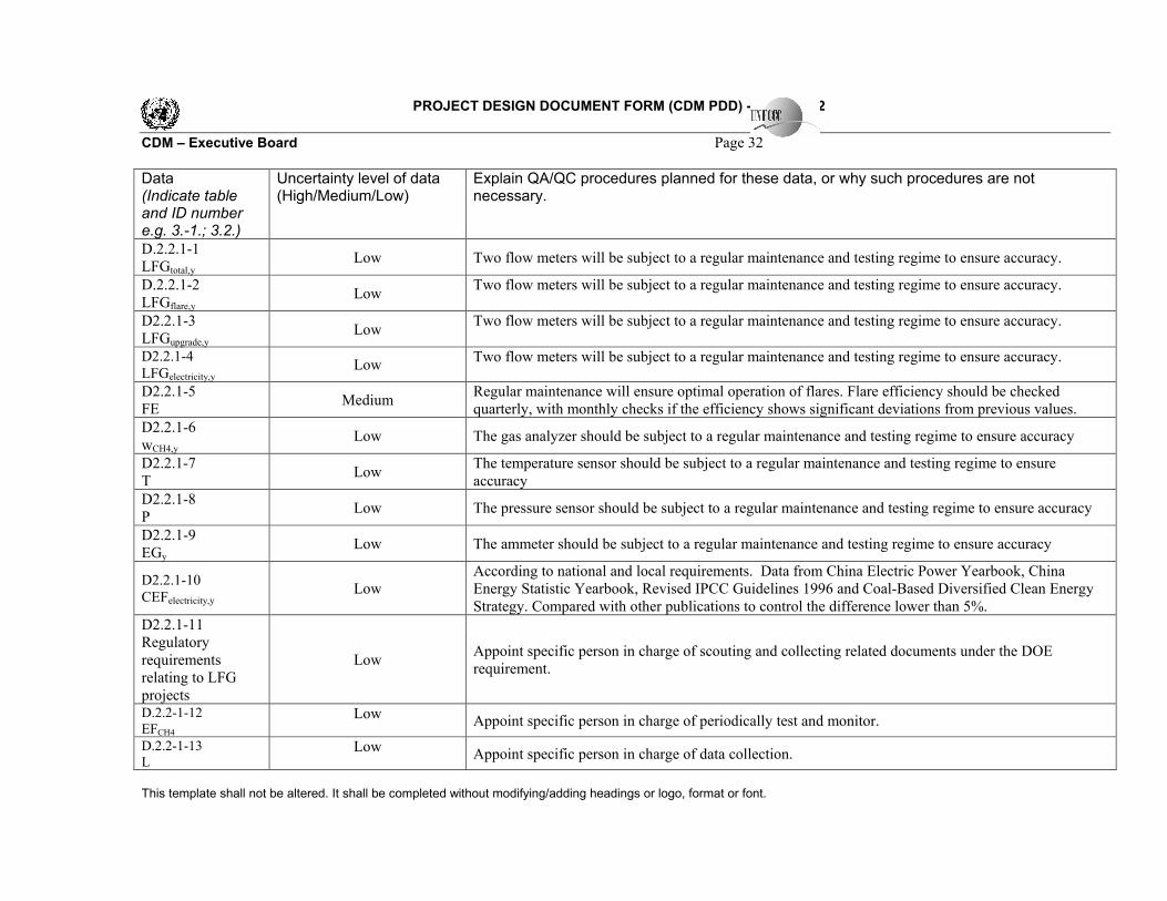
Data (Indicate table and ID number e.g. 3.-1.; 3.2.)
Uncertainty level of data (High/Medium/Low)
Explain QA/QC procedures planned for these data, or why such procedures are not necessary.
D.2.2.1-1 LFGtotal,y
Low Two flow meters will be subject to a regular maintenance and testing regime to ensure accuracy.
D.2.2.1-2 LFGflare,y
Low Two flow meters will be subject to a regular maintenance and testing regime to ensure accuracy.
D2.2.1-3 LFGupgrade,y
Low Two flow meters will be subject to a regular maintenance and testing regime to ensure accuracy.
D2.2.1-4
LFGelectricity,y Low
Two flow meters will be subject to a regular maintenance and testing regime to ensure accuracy.
D2.2.1-5 FE
Medium Regular maintenance will ensure optimal operation of flares. Flare efficiency should be checked quarterly, with monthly checks if the efficiency shows significant deviations from previous values.
D2.2.1-6 wCH4,y
Low The gas analyzer should be subject to a regular maintenance and testing regime to ensure accuracy
D2.2.1-7 T
Low The temperature sensor should be subject to a regular maintenance and testing regime to ensure accuracy
D2.2.1-8 P
Low The pressure sensor should be subject to a regular maintenance and testing regime to ensure accuracy
D2.2.1-9 EGy
Low The ammeter should be subject to a regular maintenance and testing regime to ensure accuracy
D2.2.1-10 CEFelectricity,y
Low According to national and local requirements. Data from China Electric Power Yearbook, China Energy Statistic Yearbook, Revised IPCC Guidelines 1996 and Coal-Based Diversified Clean Energy Strategy. Compared with other publications to control the difference lower than 5%.
D2.2.1-11 Regulatory requirements relating to LFG projects
Low Appoint specific person in charge of scouting and collecting related documents under the DOE requirement.
D.2.2-1-12
EFCH4
Low Appoint specific person in charge of periodically test and monitor.
D.2.2-1-13 L
Low Appoint specific person in charge of data collection.

PROJECT DESIGN DOCUMENT FORM (CDM PDD) - Version 02
CDM – Executive Board Page 33
This template shall not be altered. It shall be completed without modifying/adding headings or logo, format or font.
D.4 Please describe the operational and management structure that the project operator will implement in order to monitor emission reductions
and any leakage effects, generated by the project activity
The project owner has designated Mr.Zhang Guangyu, General Manager of Shenzhen Lisai Development Co., Ltd to be responsible for monitoring activities, includes:
� Installation of proven and qualified monitor equipment includes flow meter and gas quality analyzer. � Construct a central control system which is connected with each of monitor equipment. The system will allow automated and continuous recording and
reporting of data. The readings will be checked for any anomalies before being filed for future reference. � Appoint qualified technicians to monitor and record data according to the monitoring plan. All the technicians will receive proper training to ensure
they understand their specific tasks and handling of equipment. The records will be double checked by Mr. Zhang who will be responsible for accuracy and frequency of the measurements.
� Document data both in electronic version and hard copy in a transparent system. Receipt of electricity purchase will be obtained. � Project owner will prepare verification report required by DOE and carbon buyers according to CDM rules and ERPA. Proper management process and
routine procedures will be put in place to ensure the quality of reports. In the case of non-conformities in the implementation of the Proposed Project with relation to the monitoring plan, an analysis of non-conformity and its causes will be carried out immediately and corrective actions will be implemented.
Supported by the Project Owner, a CDM Handbook for the project owner to manage and monitor the proposed project is drafted at present. The manual is available for validation by the DOE and will be updated and revised based on the comments from the DOE.
D.5 Name of person/entity determining the monitoring methodology:
The monitoring plan study of the Proposed Project was completed on 15 October 2005 by Ms. Pan Tao, supported by Mr. Xia Zhenhua, Global Climate Change Institute, Tsinghua University, Energy Science Building-C, Tsinghua University, Haidian District, Beijing 100084, China. The study of baseline and monitoring plan received a great support from Mr. Zhang Guangyu, General manager of Shenzhen Lisai Development Co., Ltd, Mr. Yang Zhigui, Chief Engineer of Shenzhen Xiaping Landfill and Prof. Wang Wei, Department of Environmental Science and Engineering, Tsinghua University.

PROJECT DESIGN DOCUMENT FORM (CDM PDD) - Version 02
CDM – Executive Board page 34
This template shall not be altered. It shall be completed without modifying/adding headings or logo, format or font.
SECTION E. Estimation of GHG emissions by sources
E.1. Estimate of GHG emissions by sources:
The source of emissions from the Proposed Project is the combustion of LFG in the flares and automobile engines. When combusted, methane is converted into CO2. As the methane is organic in nature these emissions are not counted as project emissions. The CO2 released during the combustion process was originally fixed via biomass so that the life cycle CO2 emissions of LFG are zero. The project, however, does not collect all the methane generated. Consequently, these emissions are excluded from the ex ante estimation of emission reduction expected from the Proposed Project. Furthermore, given that the emission reduction from this type of project are measured directly, there is no need to monitor or ex ante estimate of project emissions.
E.2. Estimated leakage:
No leakage needs to be accounted for this methodology.
E.3. The sum of E.1 and E.2 representing the project activity emissions:
The sum of the Section E.1 and Section E.2 for the Proposed Project is zero.
E.4. Estimated anthropogenic emissions by sources of greenhouse gases of the baseline:
ACM0001 provide an equation for calculating the amount of methane destroyed in the baseline scenario as follows:
AFMDMD yprojectyreg ∗= ,, (4)
Where:
yregMD , : Amount of methane that would have been destroyed/combusted during the year “y” in
the absence of the Proposed Project activity (tCH4);
yprojectMD , : Amount of methane actually destroyed/combusted during the year “y” (tCH4);
AF : Adjustment factor (%). The methane destroyed by the Proposed Project is estimated ex ante using the IPCC Fist Order Decay
Model (Tier2), using the 0L and k values appropriate for the Proposed Project site and assuming that
only 48% of the LFG generated is recovered (See Annex 3). Since the ex ante estimation is merely for illustrational purposes only, the actual emission reductions will be monitored directly. Further information on the parameters used please see Annex 3 of this document. AF value is justified based on an estimation of the amount of LFG that would have been flared in the absence of the Proposed Project according to the effectiveness of the LFG collection system imposed by regulatory requirements at the time of inception of the Proposed Project (the ‘Adjustment Factor’). The landfill operator is not required to flare any amount of LFG that currently emits. It is unlikely that the Chinese government will introduce legislation requiring the collection and flaring of LFG in the foreseeable future. Moreover, there are no wells in the Xiaping Landfill prior to the implementation of the Proposed Project. Therefore the AF value is zero for the Proposed Project. The emission reductions that
would have taken place in the baseline scenario ( yregMD , ) using the equation (4) is zero.
E.5. Difference between E.4 and E.3 representing the emission reductions of the project activity:
PROJECT DESIGN DOCUMENT FORM (CDM PDD) - Version 02
CDM – Executive Board page 35
This template shall not be altered. It shall be completed without modifying/adding headings or logo, format or font.
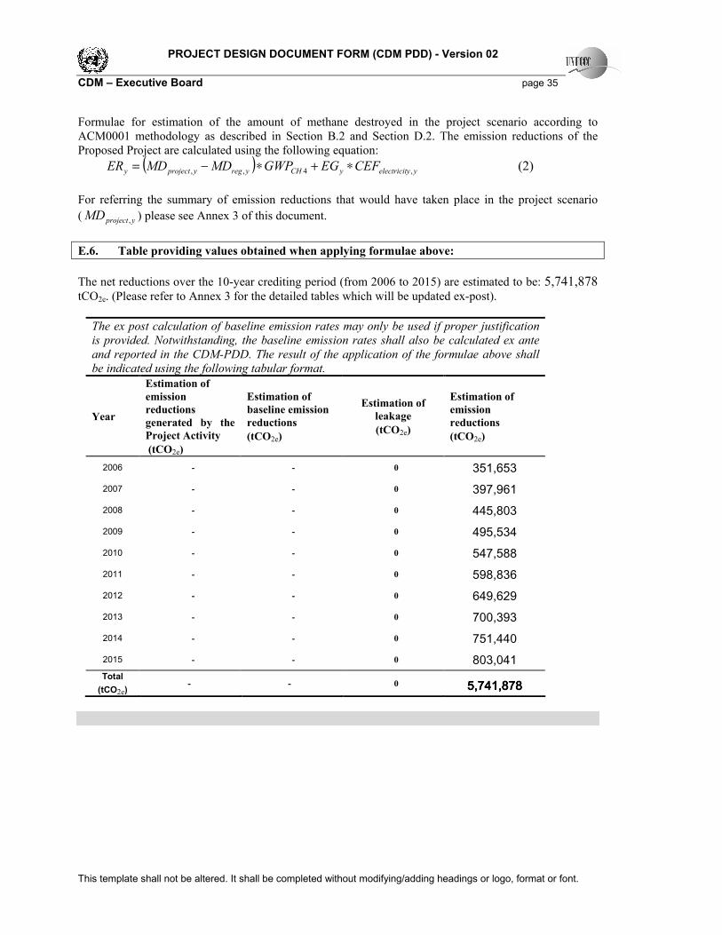
Formulae for estimation of the amount of methane destroyed in the project scenario according to ACM0001 methodology as described in Section B.2 and Section D.2. The emission reductions of the Proposed Project are calculated using the following equation:
( ) yyelectricityCHyregyprojecty CEFEGGWPMDMDER ,4,, ∗+∗−= (2)
For referring the summary of emission reductions that would have taken place in the project scenario
( yprojectMD , ) please see Annex 3 of this document.
E.6. Table providing values obtained when applying formulae above:
The net reductions over the 10-year crediting period (from 2006 to 2015) are estimated to be: 5,741,878 tCO2e. (Please refer to Annex 3 for the detailed tables which will be updated ex-post).
The ex post calculation of baseline emission rates may only be used if proper justification
is provided. Notwithstanding, the baseline emission rates shall also be calculated ex ante
and reported in the CDM-PDD. The result of the application of the formulae above shall
be indicated using the following tabular format.
Year
Estimation of
emission
reductions
generated by the
Project Activity
(tCO2e)
Estimation of
baseline emission
reductions
(tCO2e)
Estimation of
leakage
(tCO2e)
Estimation of
emission
reductions
(tCO2e)
2006 - - 0 351,653 2007 - - 0 397,961 2008 - - 0 445,803 2009 - - 0 495,534 2010 - - 0 547,588 2011 - - 0 598,836 2012 - - 0 649,629 2013 - - 0 700,393 2014 - - 0 751,440 2015 - - 0 803,041 Total
(tCO2e) - - 0 5,75,75,75,741,878 41,878 41,878 41,878
PROJECT DESIGN DOCUMENT FORM (CDM PDD) - Version 02
CDM – Executive Board page 36
This template shall not be altered. It shall be completed without modifying/adding headings or logo, format or font.
SECTION F. Environmental impacts
F.1. Documentation on the analysis of the environmental impacts, including transboundary
impacts:
An Environmental impact assessment was completed in accordance with Chinese regulation as part of the feasibility study for the Proposed Project and was approved by Environment Protection Bureau of Shenzhen in November 2005. Flowing environmental effects were identified for the Proposed Project and measures and procedures to mitigate the possible effects were provided based on the Ambient Air Quality Standard (GB3095-1996), the Integrated Wastewater Discharge Standard (GB8978-96), the Standard of Environmental Noise of Urban Area (GB3096-93), the Standard of Noise at Boundary of Industrial Enterprises (GB12348-90).
Air Quality
With periodically monitor, emission of the flaring gas will meet the leading emission criteria in the world such as in EU. Since the Proposed Project is sited in an open, even terrain and no companies or inhabitants within 300m range, the diluted flaring gas in atmosphere are viewed as almost no harm. Moreover, the implementation of the Proposed Project will significantly improve air quality of local area through avoiding uncontrolled release of LFG and odour and make contribution to protect global environment. Water Quality
Waste water, generated mainly from the system of LFG upgrade to CPLG and equipment maintenance and repair, is concentrated in the disposal pool to remove dirty oil and then, discharged into sewer with no harm to environment.
Noise
There will be some increase in noise from the site associated with implementation of the Proposed Project, the application of pumps and Roots’ blowers in LFG collection system and LFG upgrade system, the flow or ventilate of varies medium. Based on the requirements of the Standard of Environmental Noise of Urban Area (GB3096-93) and the Standard of Noise at Boundary of Industrial Enterprises (GB12348-90), following measures will be adopted to control and reduce noise:
� Establish sound insulation facilities between power plant and the control house to reduce noise impact on working condition;
� Install flexible connector, preserve heat for flue pipe and interpose reinforced rib in pipe to change vibration frequency of steel sheet, reduce flow noise and related vibration noise;
� Install silencer in input and output pipes; � Install damping device in base of equipment to reduce vibration noise; and � Periodically noise monitor for LFG collection, LFG upgrade to CPLG system and LFG power
generation system and surroundings.
In conclusion, environmental impacts arising from this project are considered insignificant.
F.2. If environmental impacts are considered significant by the project participants or the host
Party, please provide conclusions and all references to support documentation of an environmental
impact assessment undertaken in accordance with the procedures as required by the host Party:
>> Environmental impacts are not considered significant.

PROJECT DESIGN DOCUMENT FORM (CDM PDD) - Version 02
CDM – Executive Board page 37
This template shall not be altered. It shall be completed without modifying/adding headings or logo, format or font.
SECTION G. Stakeholders’ comments
G.1. Brief description how comments by local stakeholders have been invited and compiled:
>> As required by National environmental protection regulations of PRC, the Project Owner should carry out public survey during EIA process to collect stakeholders’ comments on the Proposed Project activities, therefore to guarantee the social and environmental benefits of the Proposed Project. In September 2005, staff from the Project Owner carried out a survey of the stakeholders in the area where the Proposed Project will be sited. All the parties of pertinent benefit were inquired about the project actives through questionnaire and interview. Origin data is documented by the Project Owner and the main results are summarized as follows:
Survey method
Stakeholders’ comments are collected through interview and public survey. The public survey is focused on local habitats and local employee. The interview is focused on officials of the responsible local government. The public survey and interview are conducted directly and stochastic to reflect public comments in an actual and impersonal view.
Main Content
� Public concern on pollution introduced by the Proposed Project; � Public concern on environmental impacts introduced by the Proposed Project; � Impact on local economic development and employment of the Proposed Project; � Public attitude on the implementation of the Proposed Project; � Other comments and suggestions regarding the Proposed Project (e.g. environmental protection).
Informants Structure
Totally 30 questionnaires were distributed and responses were collected through public survey. 60 percent of the informants of public questionnaire are highly educated. The interviewed officials are separately from Shenzhen Municipal Bureau for Urban Administration and Shenzhen Public Security Division.
G.2. Summary of the comments received:
>> With a complete understand, the local government provide written supporting letter to the Proposed Project, which is available for DOE/DNA. The following is the summary of the key findings through public survey:
� 93.3% of the informants are not satisfied with current living conditions and surroundings mainly for the bad odor of the landfill.
� 60% of the informants support the implementation of the Proposed Project and 26.7% of the informants oppose. The main reason for opposition is that the landfill should not be located closed to residential area. This is not opposition to the Proposed Project.
� Among the positive impacts generated by the Proposed Project, “improvement of air quality” accounts for the highest percentage (73.3%), followed by “increase of living standard” (33.3), “increase of local employment” (20%) and “increase of income” (6.7%).
� Among the negative impacts mentioned, the main concerns were the increase of noise in construction period (70%). And 50%, 40%, 40% and 26.7% of the respondents deemed that “construction waste”, “air pollution”, “construction waste water” and “land-use impacts” are important to them, respectively. The Proposed Project is located in the landfill and 300m far from the boundary of the landfill, the landfill has capability on solid waste and waste water disposal, therefore the negative impacts is not obvious and will be ended accompany with the construction
PROJECT DESIGN DOCUMENT FORM (CDM PDD) - Version 02
CDM – Executive Board page 38
This template shall not be altered. It shall be completed without modifying/adding headings or logo, format or font.
completion. � The stakeholders are care about environmental protection and have no opposite reason pointed to
the construction and implementation of the Proposed Project.
G.3. Report on how due account was taken of any comments received:
During the construction and implementation of the Proposed Project, the Project Owner should attach importance to stakeholders’ comments, seriously carry out environmental protection measures set in EIA and promote integrated benefits of environment, society and economy. The Proposed Project is in nature an environmental protection project and almost has no pollution. However, the public has no clear understanding on this, the Project Owner should enhance communication with the public. Since the local government and public show their support to the construction and implementation of the Proposed Project, therefore there is no need to modify the project due to the comments received.

PROJECT DESIGN DOCUMENT FORM (CDM PDD) - Version 02
CDM – Executive Board page 39
This template shall not be altered. It shall be completed without modifying/adding headings or logo, format or font.
Annex 1
CONTACT INFORMATION ON PARTICIPANTS IN THE PROJECT ACTIVITY
Organization: Shenzhen Lisai Development Co., Ltd
Street/P.O.Box: Bagua Sanlu Street, Futian district
Building: Room 701A, Rongsheng Building
City: Shenzhen City
State/Region: Guangdong Province
Postfix/ZIP: 518029
Country: People’s Republic of China
Telephone: +86-0755-2584-6981
FAX: +86-0755-2584-6990
E-Mail: [email protected]
URL: http://www.szbaepb.gov.cn/kjcy/kjcy_031.asp
Represented by: Zhang Guangyu
Title: General Manager
Salutation: Mr.
Last Name: Zhang
Middle Name: -
First Name: Guangyu
Department: -
Mobile: 13924674546
Direct FAX: +86-0755-2584-6990
Direct tel: +86-0755-2584-6981
Personal E-Mail: [email protected]
The following are the contact details for the other Parties involved:
Organization: Beijing Sower Technology Development Co., Ltd.
Street/P.O.Box: No. Bing 33, Qinghuayuan Region, Haidian Districit
Building: Room 4171, Sancaitang Building
City: Beijing
State/Region: -
Postfix/ZIP: 100084
Country: People’s Republic of China
Telephone: (8610) 6265 5492
FAX: (8610) 6265 5492
E-Mail: [email protected]
URL: http://www.sowertech.com
Represented by: Deng Zhou
Title: Project Manager
Salutation: Mr
Last Name: Deng
Middle Name:
First Name: Zhou
Department: -
Mobile: 1391 103 1336
Direct FAX: (8610) 62565492
Direct tel: (8610) 62565492
Personal E-Mail: [email protected]

PROJECT DESIGN DOCUMENT FORM (CDM PDD) - Version 02
CDM – Executive Board page 40
This template shall not be altered. It shall be completed without modifying/adding headings or logo, format or font.
Annex 2
INFORMATION REGARDING PUBLIC FUNDING
There is no public funding for the Proposed Project.
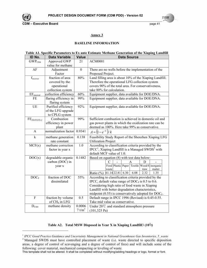
PROJECT DESIGN DOCUMENT FORM (CDM PDD) - Version 02
CDM – Executive Board page 41
This template shall not be altered. It shall be completed without modifying/adding headings or logo, format or font.
Annex 3
BASELINE INFORMATION
Table A1. Specific Parameters to Ex ante Estimate Methane Generation of the Xiaping Landfill
ID No. Data Variable Value Data Source
GWPCH4 Approved GWP value for methane
21 ACM0001
AF Adjustment Factor
0 There are no wells before the implementation of the Proposed Project.
frecover fraction of area covered by the operational
collection system
80% Land filling area is about 10% of the Xiaping Landfill. Therefore the operational LFG collection system covers 90% of the total area. For conservativeness, take 80% for calculation.
EFrecover collection efficiency 60% Equipment supplier, data available for DOE/DNA.
FE flaring efficiency in flaring system
99% Equipment supplier, data available for DOE/DNA.
UE Purified efficiency of the LFG upgrade to CPLG system
92% Equipment supplier, data available for DOE/DNA.
FEelectricity,y Combustion efficiency in power
plant
99% Sufficient combustion is achieved in domestic oil and gas power plants in which the oxidization rate can be deemed as 100%. Here take 99% as conservative.
A normalization factor 0.9341 ( ) keA k /1 −−=
k methane generation rate constant
0.138 Feasibility Study Report of the Shenzhen Xiaping LFG Utilization Project
MCF(x) methane correction factor in year x
1.0 According to classification criteria provided by the IPCC1, Xiaping Landfill is a Managed SWDS2 with default MCF value of 1.0.
DOC(x) degradable organic carbon (DOC) in
year x
0.1482 Based on equation (8) with test data below:
C - A D - Food
waste
Plastic Paper Textile Wood/S
traw
inorganic
matter
Ratio (%) 61.14 22.81 6.30 6.08 2.32 1.35 DOCF fraction of DOC
dissimilated 55% According to classification criteria provided by the
IPCC, default value range of DOCF is 0.5 to 0.6. Considering high ratio of food waste in Xiaping Landfill with better degradation characteristics, midpoint (0.55) is conservatively adopted for DOCF.
F fraction by volume of CH4 in LFG
0.5 Default range in IPCC 1996 (Revised) is 0.45-0.55. Take mid value as conservative.
DCH4 methane density 0.00067 t/m3
Under 20℃ and standard atmosphere pressure
(101,325 Pa)
Table A2. Total MSW Disposed in Year X in Xiaping Landfill3 (103t)
1 IPCC Good Practice Guidance and Uncertainty Management in National Greenhouse Gas Inventories, 5_waste 2 Managed SWDS must have controlled placement of waste (i.e. waste directed to specific deposition areas, a degree of control of scavenging and a degree of control of fires) and will include some of the following: cover material, mechanical compacting or leveling of waste.

PROJECT DESIGN DOCUMENT FORM (CDM PDD) - Version 02
CDM – Executive Board page 42
This template shall not be altered. It shall be completed without modifying/adding headings or logo, format or font.
Year 1998 1999 2000 2001 2002 2003 2004 2005
MSWfilled 581 654 712 841 1016 1118 1207 1304
Year 2006 2007 2008 2009 2010 2011 2012 2013
MSWfilled 1408 1521 1643 1774 1916 2012 2112 2218
Year 2014 2015 2016 2017 2018 2019 2020 2021
MSWfilled 2329 2445 2519 2594 2672 2752 2835 2920
Table A3 listed the LFG generated in year X in Xiaping Landfill.
Table A3. LFG generated in year X in Xiaping Landfill((((t))))
Year 1998 1999 2000 2001 2002 2003 2004 2005
Qy (t) 3545 7078 10510 14286 18643 23061 27453 31870 Year 2006 2007 2008 2009 2010 2011 2012 2013
Qy (t) 36353 40947 45693 50626 55791 60875 65914 70950 Year 2014 2015 2016 2017 2018 2019 2020 2021
Qy (t) 76014 81133 86044 90779 95380 99876 104299 108670 The data used for calculation of the weighted average emissions of Guangdong Grid is listed in table A4 and A5. The main sources of data are China Electric Power Yearbook and China Energy Statistic Yearbook (P218-221). The defaults used for calculation of calorific values for fuel types and fuel oxidization came from the Revised IPCC Guideline 1996 and Coal-Based Diversified Clean Energy
Strategy. The weighted average emission factor ( yyelectricitCEF , ) is 0.7551 tCO2e/MWh.
Talbe A4. Basic data of Guangdong Grid in 2003
4
Power generation technology option Year Installed capacity
(MW))))
Power generation
(TWh)
Hydropower Conventional 2003 5707.2 14.930 Pumped storage 2003 2400.0 2.206 Total 2003 8107.2 17.136
Fuel fired power Coal-fired 2003 17057.8 104.459
Oil-fired 2003 10162.7 38.828
Gas-fired 2003 0.0 0.0
Waste incineration 2003 11.0 0.064
Total 2003 27231.4 143.351
Nuclear power 2003 3780.0 28.930
Wind power 2003 83.4 0.159
Total 2003 39202.0 189.576
Table A5. Fuel consumption and GHG emissions of the Guangdong Grid in 2003
Fuel
Unit
A
Consumption
B
Emission Coefficient
C
(tC/TJ)
NCV
D
(TJ/A)
Emission
E=BXCXDX44/12
(tCO2e)
Raw coal 103t 44917.9 24.74 209.08 85,192,833 Clean coal 103t 0.5 24.74 263.44 1,195 Other coal gas 106m3 321 20.2 522.7 124,274 Crude oil 103t 68.5 20 418.16 210,056
3 Feasibility Study Report of Xiaping LFG Utilization Project
4 Data Resource: China Electric Power Yearbook 2004, P678-680.

PROJECT DESIGN DOCUMENT FORM (CDM PDD) - Version 02
CDM – Executive Board page 43
This template shall not be altered. It shall be completed without modifying/adding headings or logo, format or font.
Gasoline 103t 0.2 18.9 430.7 597 Diesel 103t 319 20.2 426.52 1,007,750 Fuel oil 103t 6272.2 21.1 418.16 20,291,599 Refinery gas 103t 28.5 20 460.55 96,255 Other petroleum products 103t 113.5 20 400.19 333,091 Nature Gas 106m3 451 15.3 3893.1 984,997 Other Energy 103tce 932.1 0 292.712 0
Total 108,242,647108,242,647108,242,647108,242,647
Main electricity consumer of the Proposed Project includes five Roots’ blower (30 KW/set, one reserve), one set of LFG upgrade system (270 KW) with one compressor (75 KW). Assuming the capacity of the related centre control system and monitor equipment is totally 25 KW, the total capacity of the Proposed Project is 1370 KW. Supposing all electricity consumers to be continuously operated throughout the year
(8760 h/a) and the line loss of the Guangdong Grid is 8%5。
Calculated based on equation described in Section B.2 with the data above, the amount of methane generation, methane destroyed and emission reduction of the Proposed Project are shown in Table A6. Please note: since the time schedule for the expansion of LFG to CPLG system and the operation of power plant is not confirmed, the calculation in Annex 3 only considers the first stage of LFG upgrade to CPLG system (500 m3/h) and the flaring system. Monitor report with actual emission reduction of the Proposed Project should be adjusted based on the actual conditions.
5 It is pointed out in the Tenth-Five Plan of Power Industry that the national average line loss is 7% in year 2000. The line loss is decreased later on. Here take 8% as conservative.
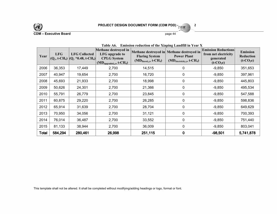
PROJECT DESIGN DOCUMENT FORM (CDM PDD) - Version 02
CDM – Executive Board page 44
This template shall not be altered. It shall be completed without modifying/adding headings or logo, format or font.
Table A6. Emission reduction of the Xiaping Landfill in Year X
Year LFG
(Qy, t-CH4)
LFG Collected
(Qy *0.48, t-CH4)
Methane destroyed in
LFG upgrade to
CPLG System
(MDupgraded,,y, t-CH4)
Methane destroyed in
Flaring System
(MDflared,,y, t-CH4)
Methane destroyed in
Power Plant
(MDelectricity,y, t-CH4)
Emission Reductions
from net electricity
generated
(t-CO2e)
Emission
Reduction
(t-CO2e)
2006 36,353 17,449 2,700 14,515 0 -9,850 351,653
2007 40,947 19,654 2,700 16,720 0 -9,850 397,961
2008 45,693 21,933 2,700 18,998 0 -9,850 445,803
2009 50,626 24,301 2,700 21,366 0 -9,850 495,534
2010 55,791 26,779 2,700 23,845 0 -9,850 547,588
2011 60,875 29,220 2,700 26,285 0 -9,850 598,836
2012 65,914 31,639 2,700 28,704 0 -9,850 649,629
2013 70,950 34,056 2,700 31,121 0 -9,850 700,393
2014 76,014 36,487 2,700 33,552 0 -9,850 751,440
2015 81,133 38,944 2,700 36,009 0 -9,850 803,041
TotalTotalTotalTotal 555584,29484,29484,29484,294 280,461280,461280,461280,461 26,99826,99826,99826,998 251,115 251,115 251,115 251,115 0000 ----98,50198,50198,50198,501 5,741,878 5,741,878 5,741,878 5,741,878

PROJECT DESIGN DOCUMENT FORM (CDM PDD) - Version 02
CDM – Executive Board page 45
This template shall not be altered. It shall be completed without modifying/adding headings or logo, format or font.
Annex 4
MONITORING PLAN
Monitoring plan is a division and schedule of a series of monitoring tasks. Monitoring tasks must be implemented according to the monitoring plan in order to ensure that the real, measurable and long-term GHG emission reduction for the Proposed Project is monitored and reported.
1. What is required by the monitoring plan?
Managers of the Proposed Project must maintain credible, transparent, and adequate data estimation, measurement, collection, and tracking systems to maintain the information required for an audit of an emission reduction project. These records and monitoring systems are needed to allow the selected DOE to verify project performance as part of the verification and certification process. This process also reinforces that CO2 reductions are real and credible to the buyers of the Certified Emissions Reductions (CERs). Emission reductions will be achieved through avoided uncontrolled release of LFG of Landfill by the Proposed Project. The amount of the methane captured and destroyed by the Proposed Project and the ‘Adjustment Factor’ which defines baseline emissions are therefore defined as the key activities to monitor. The monitoring plan provides the requirements and instructions for: � Establishing and maintaining the appropriate monitoring systems for methane destroyed by the
Proposed Project; � Quality control of the measurements; � Procedures for the periodic calculation of GHG emission reductions; � Assigning monitoring responsibilities to personnel; � Data storage and filing system; � Preparing for the requirements of an independent, third party auditor/verifier.
2. Who uses the monitoring plan?
The Shenzhen Lisai Development Co. Ltd., the Proposed Project owner, will use this document as a monitoring guideline in realizing the project emission reduction credits and will adhere to the guidelines set out in this monitoring plan. This plan chould be modified according to actual conditions and requirements of DOE in order to ensure that the monitoring is credible, transparent and conservative.
3. Key definitions
The monitoring plan will use the following definitions of monitoring and verification. � Monitoring: the systematic surveillance of the project’s performance by measuring and recording
performance-related indicators relevant in the context of GHG emission reductions. � Verification: the periodic ex-post auditing of monitoring results, the assessment of achieved emission
reductions and of the project’s continued conformance with all relevant project criteria by a selected Designated Operational Entity.
4. Calibration of Meters & Metering
PROJECT DESIGN DOCUMENT FORM (CDM PDD) - Version 02
CDM – Executive Board page 46
This template shall not be altered. It shall be completed without modifying/adding headings or logo, format or font.
An agreement should be signed between the Proposed Project owner and the Xiaping Landfill, local grid company separately to define the metering arrangements and the required quality control procedures to ensure accuracy. � The metering equipment will be properly calibrated and checked annually for accuracy and the
metering equipment shall have sufficient accuracy so that error resulting from such equipment shall not exceed +0.5% of full-scale rating.
� Dual flow meters shall be jointly inspected and sealed on behalf of the parties concerned and shall not be interfered with by either party except in the presence of the other party or its accredited representatives.
� The electricity recorded by the Main Meters alone will suffice for the purpose of billing and emission reduction verification as long as the error in the Main Meter is within the permissible limits.
Calibration records will be maintained by the Proposed Project owner and the third party designated.
5. Monitoring
The monitor of the Proposed Project is focused on electricity input and output and methane destroyed. The meter reading will be readily accessible for DOE. Calibration tests records will be maintain for verification. Data required for calculating the baseline emissions factor for Guangdong Grid is obtained from the China Electric Power Yearbook, China Energy Statistics Yearbook, Coal-Based Diversified Clean Energy Strategy and Revised IPCC Guideline 1996. The Proposed Project owner should collect and documented the latest China Electric Power Yearbook and China Energy Statistics Yearbook annually. If data for determining the baseline emission factor are no longer provided by the China Electric Power Yearbook and the China Energy Statistics Yearbook, the Proposed Project owner should notify the CDM developer of the Proposed Project or other qualified entity to redesign the access to obtain the data to calculate the conservative baseline emission factor of the project boundary. The quality assurance and quality control procedures for recording, maintaining and archiving data shall be improved as part of this CDM project activity. This is an on-going process which will be ensured through the CDM mechanism in terms of the need for verification of the emissions on an annual basis according to this PDD and the CDM Handbook.
6. Data Management System
This provides information on record keeping of the data collected during monitoring. Record keeping is the most important exercise in relation to the monitoring process. Without accurate and efficient record keeping, project emission reductions cannot be verified. Below follows an outline of how project related records will be managed. Overall responsibility for monitoring of GHG emissions reduction will rest with the CDM responsible person of the Proposed Project. The CDM manual sets out the procedures for tracking information from the primary source to the end-data calculations, in paper document format. If data and information are from internet, the website must be provided. Moreover, the credibility and reliability of those data and information from internet must be confirmed by the CDM developer or other qualified entities. It is the responsibility of the Proposed Project owner to provide additional necessary data and information for validation and verification requirements of respective DOE. Physical documentation such as paper-based maps, diagrams, recipients and environmental impact assessment will be collated in a central place, together with this monitoring plan. In order to facilitate

PROJECT DESIGN DOCUMENT FORM (CDM PDD) - Version 02
CDM – Executive Board page 47
This template shall not be altered. It shall be completed without modifying/adding headings or logo, format or font.
auditor’s reference, monitoring results will be indexed. All paper-based information will be stored by the Proposed Project owner and kept at least one copy. The responsible person for the information management system for emissions reduction monitoring must be qualified as a statistician. Table A7 below outlines the main documents relevant to monitoring and verification of the Proposed Project.
Table A7. Main Documents on Monitoring and Verification
I.D. No. Document Title Main Content Source
F-1 PDD, including the electronic spreadsheets and supporting documentation (assumptions, estimations, measurement, etc.)
Calculation procedure of emission reduction and monitoring items
PDD in English and Chinese must be documented by the
Proposed Project owner,or directly download from UNFCCC website
F-2 Monitoring Quality Control and Quality Assurance Report
Equipment and national and industry standards
Proposed Project owner
F-3 The report on qualifications of the persons responsible for the monitoring and calculation
i.e. the title of a technical post, working experience etc.
Proposed Project owner
F-4 The report on monitoring and checking of methane destroyed, electricity input and output.
Record based on monthly meter reading and sale receipts of upgraded LFG, electricity.
Proposed Project owner
F-5 Record on maintenance and calibration of metering equipment
Reasons for maintenance and calibration and the precision after maintenance and calibration
Proposed Project owner
F-6 The report on baseline emission factor calculation
Data sources and calculation procedure
Proposed Project owner
F-7 Record on emission reduction Quarterly calculation Proposed Project owner F-8 Letter of confirmation on F-2 to F-7 Make confirmation of
monitoring and calculation data and procedure from F-2 to F-7
Proposed Project owner
F-9 Project Management Record (including data collection and management system)
Comprehensively and truly reflect the management and the operation of the Proposed Project
Proposed Project owner
7. Verification Procedure
The verification procedure of the monitoring results of the project is a mandatory process required for all CDM projects. The main objective of the verification is to independently verify that the Proposed Project has achieved the emission reductions as reported and projected in the PDD. It is expected that the verification could be done annually. Main verification activities include:
� The Proposed Project owner should sign a verification service agreement with specific DOE and
comply with the time framework set by CDM EB while consider of the buyer’s schedule to carry out verification activities. The Proposed Project owner should prepare for and conduct verification activities with high efficiency and high quality.
� The Proposed Project owner should provide completed necessary information for verification to the
DOE before and during verification activities. � The Proposed Project owner should cooperate with the DOE and, instruct its staff and manager to be
available for interviews and respond honestly to all questions relevant to verification from the DOE.
PROJECT DESIGN DOCUMENT FORM (CDM PDD) - Version 02
CDM – Executive Board page 48
This template shall not be altered. It shall be completed without modifying/adding headings or logo, format or font.
� If the Proposed Project owner deems that requirements of DOE beyond the scope of verification activities authorized by CDM EB, he should contact the CDM developer of the Proposed Project or other qualified entities to determine whether the requirements of DOE are reasonable. If the requirements are considered unreasonable, a rejection letter in a written format should be provided to the DOE with justifiable reasons. If the project owner and the DOE cannot reach an agreement on these requirements, the matter should be submitted to CDM EB or UNFCCC for arbitration.
The Proposed Project owner should designate a person in charge of the overall responsibility for the monitoring and verification procedure and act as the focal point for DOE.

PROJECT DESIGN DOCUMENT FORM (CDM PDD) - Version 02
CDM – Executive Board page 49
This template shall not be altered. It shall be completed without modifying/adding headings or logo, format or font.
Annex 5
List of key abbreviations
CDM Clean Development Mechanism CDM EB CDM Executive Board CER Certified Emission Reduction CO2e Carbon Dioxide Equivalent CPLG Compressed Purified Landfill Gas DOE Designated Operation Entity ERPA Emission Reduction Purchase Agreement GHG Greenhouse Gas GWh Gigawatt-hour IRR Internal Rate of Return KWh kilowatt-hour Mt million tonnes MW Megawatt NCV Net Calorific Value RE Renewable Energy t ton tce tons of standard coal equivalent TWh Terawatt-hour VAT Value-added Tax

PROJECT DESIGN DOCUMENT FORM (CDM PDD) - Version 02
CDM – Executive Board page 50
This template shall not be altered. It shall be completed without modifying/adding headings or logo, format or font.
Reference
IPCC(2000). Good Practice Guidance and Uncertainty Management in National Greenhouse Gas
Inventories. http://www.ipcc-nggip.iges.or.jp/public/gp/english/ IPCC(1996). Revised 1996 IPCC Guidelines for National Greenhouse Gas Inventories. http://www.ipcc-nggip.iges.or.jp/public/gl/invs1.htm Project Design Document (PDD) of Nanjing Tianjingwa Landfill Gas to Electricity Project. Available from http://www.dnv.com/certification/climatechange/Projects/ProjectList.asp?Country=China Project Design Document (PDD) of Meizhou Landfills Gas Recovery and Utilization as Energy Project. Available from http://www.dnv.com/certification/climatechange/Projects/ProjectList.asp?Country=China National Action Plan for Collection and Utilization of Landfill Gas (12/2001)
Technical Code for Sanitary Landfill of Municipal Domestic Refuse (CJJ17-2001)
Standard for Pollution Control on the Landfill Site for Domestic Waste (GB16889-1997)
Waste Incineration Generation Technology, complied by Zhang Yanguo, published by Publishing House of China Water Conservancy & Hydropower, March 2004.