Leveraging Open Source Power Measurement Standard Solution
25
Embedded Linux Conference Europe October 15th, 2014 Düsseldorf, Germany Leveraging Open-Source Power Measurement Standard Solution Genesis of a new power measurement initiative Patrick Titiano, System Power Management Expert, BayLibre co-founder. www.baylibre.com
-
Upload
baylibre -
Category
Devices & Hardware
-
view
72 -
download
2
Transcript of Leveraging Open Source Power Measurement Standard Solution

Embedded Linux Conference Europe October 15th, 2014 Düsseldorf, Germany
Leveraging Open-Source Power Measurement Standard Solution
Genesis of a new power measurement initiative
Patrick Titiano, System Power Management Expert,
BayLibre co-founder. www.baylibre.com
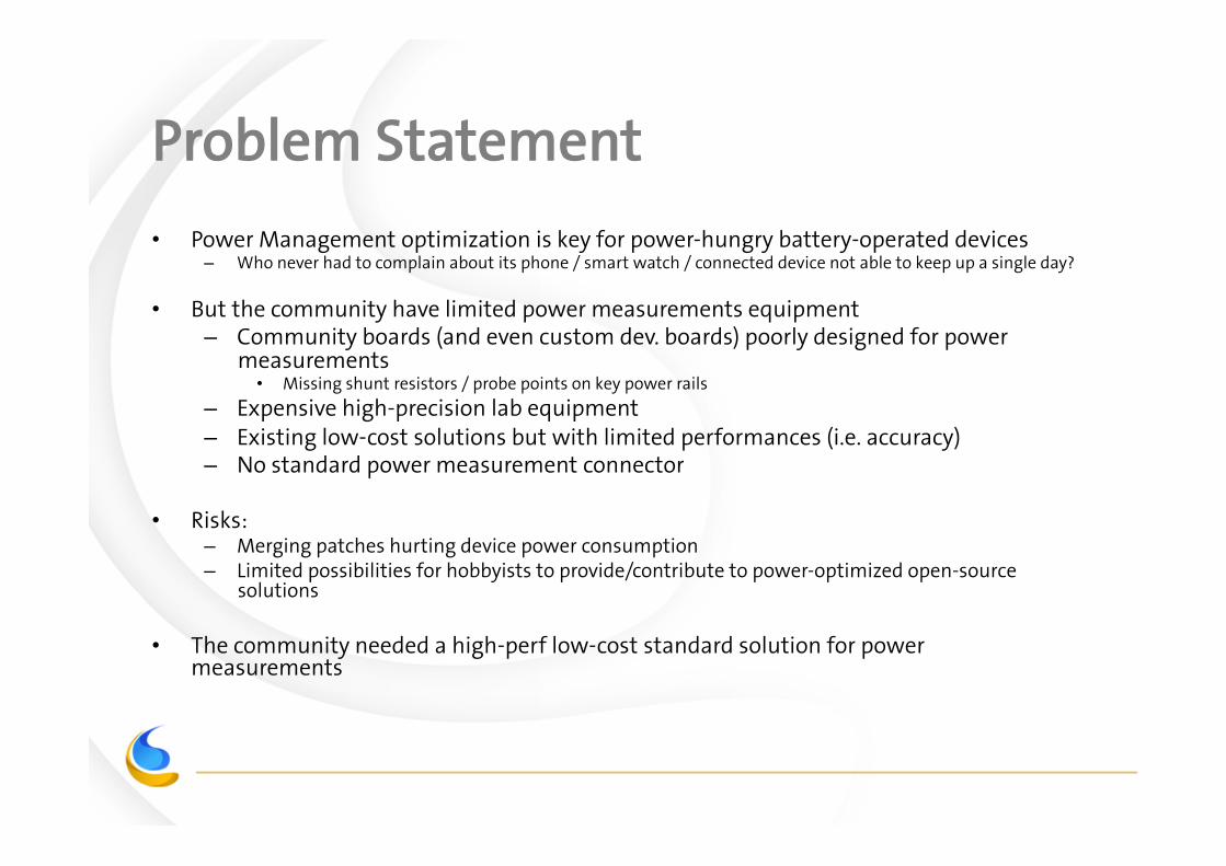
Problem Statement
• Power Management optimization is key for power-hungry battery-operated devices – Who never had to complain about its phone / smart watch / connected device not able to keep up a single day?
• But the community have limited power measurements equipment – Community boards (and even custom dev. boards) poorly designed for power
measurements • Missing shunt resistors / probe points on key power rails
– Expensive high-precision lab equipment – Existing low-cost solutions but with limited performances (i.e. accuracy) – No standard power measurement connector
• Risks: – Merging patches hurting device power consumption – Limited possibilities for hobbyists to provide/contribute to power-optimized open-source
solutions
• The community needed a high-perf low-cost standard solution for power measurements

Menu of the Day
• Power Measurement Basics – Board Requirements
– ADC resolution
– Shunt Resistor selection
• The “ACME” Initiative
– Rationale
• Demo
• Q & A

Power Measurement Basics Test points, ADC resolution, Sampling Rates, Shunt Resistor selection, …
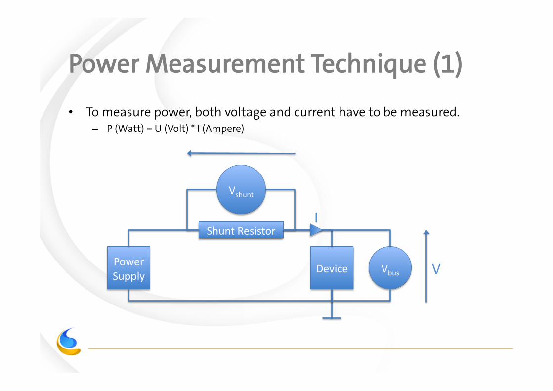
Power Measurement Technique (1)
• To measure power, both voltage and current have to be measured. – P (Watt) = U (Volt) * I (Ampere)
Power Supply
Vshunt
Vbus Device
Shunt Resistor I
V

Power Measurement Technique (2)
• To measure the supply voltage: – No extra onboard component required, but only 2 test points (Vdd + gnd)
at current sink (e.g. SoC) ends.
• To measure the current consumption: – An additional shunt resistor shall be placed in series with the power line.
– Following Ohm's law (U = R * I, i.e. I = Vshunt / Rshunt), by measuring the voltage drop at the resistor ends and knowing the resistor value, the current can be calculated.
– Accurate current measurement requires high-precision shunt resistor. • As per Ohm's law, there is a 1 to 1 ratio between resistor value tolerance and
measurement precision. – E.g. 5% resistor -> 5% current measurement accuracy, 0.1% resistor -> 0.1% current
measurement accuracy
• Also a very low temperature coefficient variation is required (e.g. 110ppm/)

Power Measurement Technique (3)
– The choice of the shunt resistor value is of highest importance • Further details in next slides
– Current and voltage are dynamic analog variables. • Must be sampled at a sufficient rate ( e.g. > 1Ksample/s), • Otherwise good amount of consumed energy may be missed =>
inaccurate measurement
– Voltage and current shall be measured at the same time for proper instantaneous power consumption computation.
– Averaging power consumption of a given amount of [U, I] measurements is done by averaging (U * I). • A common error is to average U and I, then compute the Uavg * Iavg
• Pavg = avg(U * I) != Uavg * Iavg
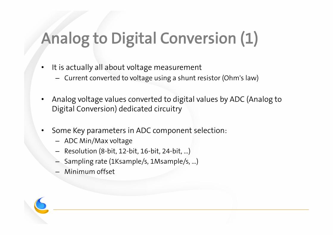
Analog to Digital Conversion (1)
• It is actually all about voltage measurement – Current converted to voltage using a shunt resistor (Ohm's law)
• Analog voltage values converted to digital values by ADC (Analog to Digital Conversion) dedicated circuitry
• Some Key parameters in ADC component selection: – ADC Min/Max voltage
– Resolution (8-bit, 12-bit, 16-bit, 24-bit, …)
– Sampling rate (1Ksample/s, 1Msample/s, …)
– Minimum offset
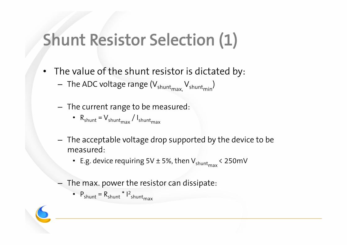
Shunt Resistor Selection (1)
• The value of the shunt resistor is dictated by: – The ADC voltage range (Vshuntmax,
Vshuntmin)
– The current range to be measured: • Rshunt = Vshuntmax
/ Ishuntmax
– The acceptable voltage drop supported by the device to be measured: • E.g. device requiring 5V ± 5%, then Vshuntmax
< 250mV
– The max. power the resistor can dissipate: • Pshunt = Rshunt * I2
shuntmax

Shunt Resistor Selection Example (1)
• Example: – Conditions:
• ADC TI INA226: – 16-bit ADC,
– Vshuntmax = 81,92mV,
– Vshuntmin = 2.5uV
• Imax = 1.5A
• Device operating range: 5V ± 5%
– Matching shunt resistor: • Rshunt = 54,6mΩΩ ≃ 50mΩΩ
• Pshunt = 0,123W => 1/2W shunt resistor OK
• Vshuntmax= 81,92mV < 250mV => within device operating range

Shunt Resistor Selection Example (2)
Exceed accepted drop-‐out
Exceed shunt max power (1/2W)
Close to ADC limits
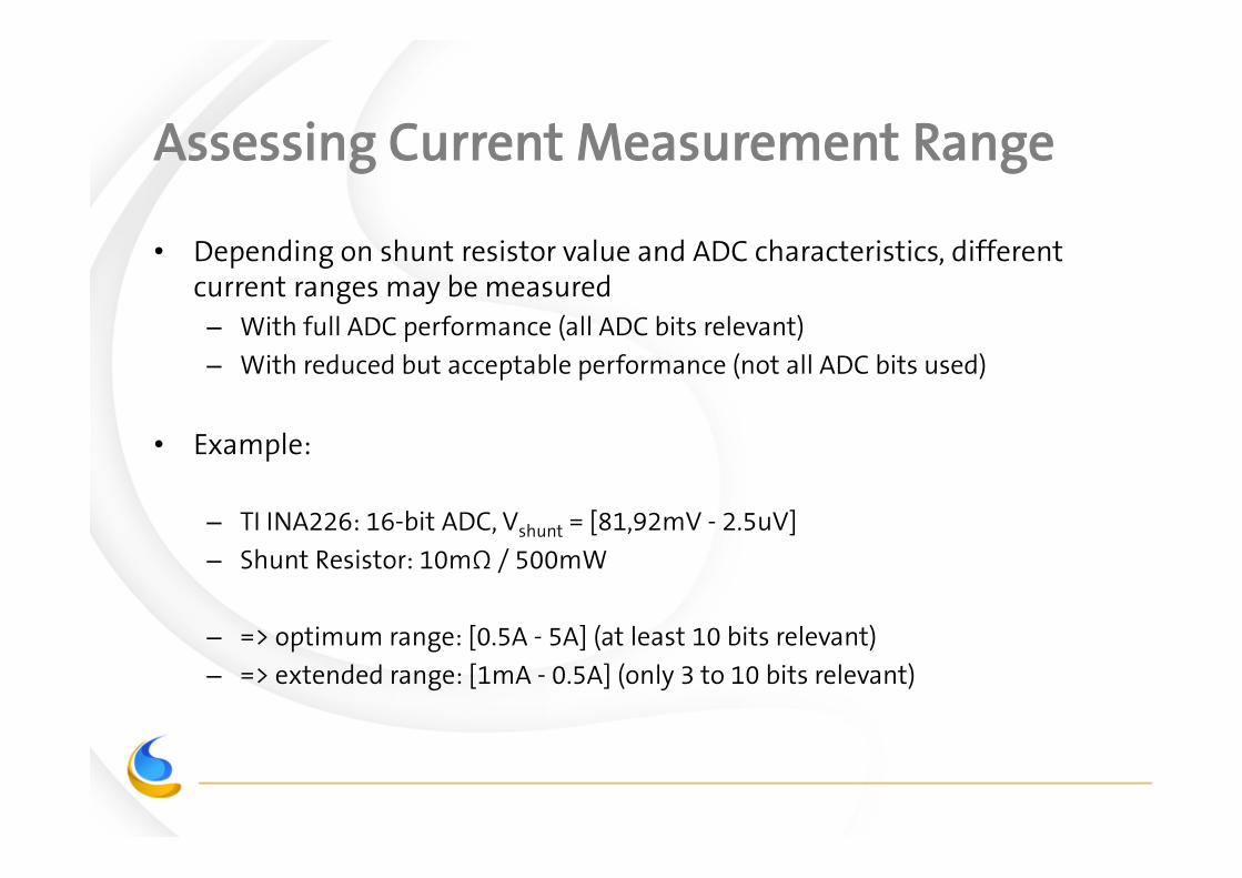
Assessing Current Measurement Range
• Depending on shunt resistor value and ADC characteristics, different current ranges may be measured – With full ADC performance (all ADC bits relevant)
– With reduced but acceptable performance (not all ADC bits used)
• Example:
– TI INA226: 16-bit ADC, Vshunt = [81,92mV - 2.5uV]
– Shunt Resistor: 10mΩΩ / 500mW
– => optimum range: [0.5A - 5A] (at least 10 bits relevant)
– => extended range: [1mA - 0.5A] (only 3 to 10 bits relevant)
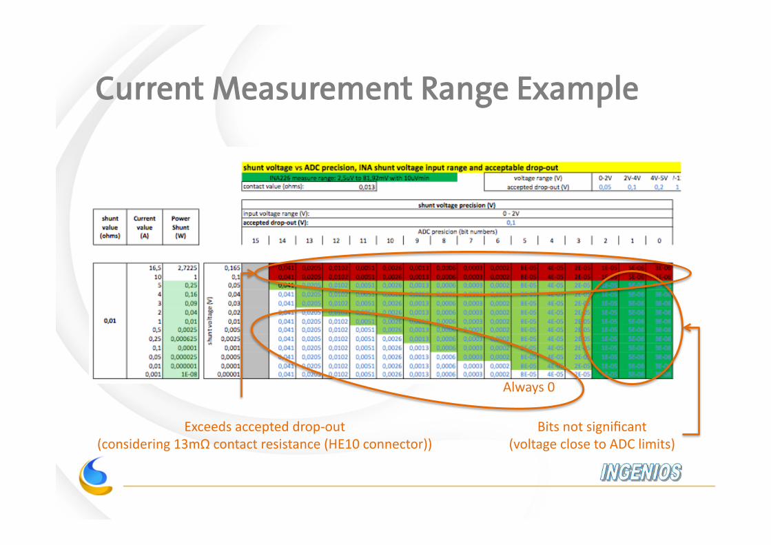
Current Measurement Range Example
Exceeds accepted drop-‐out (considering 13mΩ contact resistance (HE10 connector))
Always 0
Bits not significant (voltage close to ADC limits)

The “ACME” initiative Another Cute Measurement Equipment Objectives, key features & decisions, status

ACME Cape: Why?
• As power management experts, we used to be frustrated by the existing equipment, either – Not matching our needs / not adapted,
– Windows-only / not Linux-friendly,
– Proprietary drivers,
– Limited/ not flexible proprietary application suite,
– Limited automation capabilities,
– Too expensive,
– Too complicated to use,
– Not accurate enough,
– Lack of standard power measurement connector (ad hoc solutions only)
– …
• => We decided to close all these gaps and provide the community with the most flexible low-cost but high-perf solution – Challenging, isn’t it?!
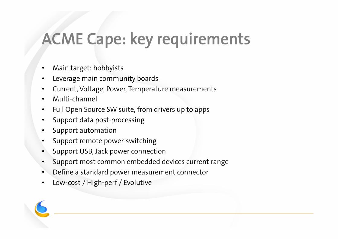
ACME Cape: key requirements
• Main target: hobbyists
• Leverage main community boards
• Current, Voltage, Power, Temperature measurements
• Multi-channel
• Full Open Source SW suite, from drivers up to apps
• Support data post-processing
• Support automation
• Support remote power-switching
• Support USB, Jack power connection
• Support most common embedded devices current range
• Define a standard power measurement connector
• Low-cost / High-perf / Evolutive
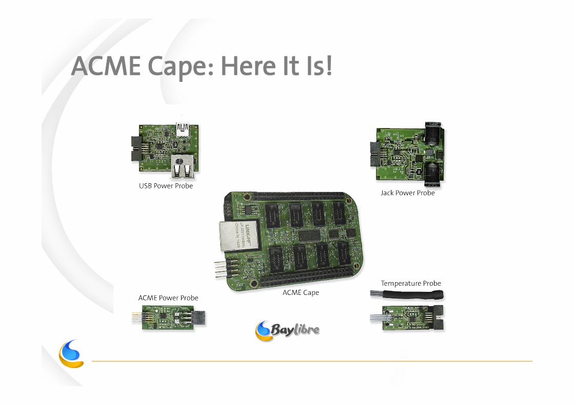
ACME Cape: Here It Is!

ACME Cape: Key Features
• Leverage Beagle Bone Black for data processing (1GHz CPU)
• Multi-channel – 8, up to 16 with Cape stacking
• All-in-one solution for power measurement, power control, and temperature measurement
• Flexible / Evolutive – Extension connector for use with other HW than BBB – New probes can be designed, w/o HW change required on ACME cape
• Complete Open Source SW Suite
• Standard ACME Probe Connector (free of charge)
• Low-cost

ACME Cape: Key Decisions
• Probes include the ADC for best accuracy – No more long wires between shunt and ADC
• Use TI INA226 & TMP435 components featuring upstream Linux drivers
• Flexible Client/Server SW Architecture – To handle any sort of usage (local/remote/simultaneous/…)
• Define a standard low-cost power measurement connector (free of charge) and provide power probes following this standard
• Scalable HW design to reduce cost

ACME Cape: Standard PM Connector
• Objectives: – Provide a standard way to get development board ready for power measurements
• No more HW modification
– Get rid of proprietary / ad hoc solutions • Today: new board = new HW tweaks = no reuse
– Ultra low-cost, low footprint, easy integration for board manufacturers
– Open standard / free of charge (no licensing fee)
• Our solution: the ACME Probe Connector – Leveraging good old world-famous HE10 connector
– Handle up to 6A (3A single line)
– Shunt resistor may or may not be populated on the PCB • HE10 ACME probes available with or without shunt resistor
– Proof of concept demonstrated on SAMA5D3-XPlained board
Gnd
V+shunt V-‐
shunt

ACME Cape vs NI-DAQ
Feature NI-‐DAQ NI USB-‐6002 ACME Solu9on
ADC ResoluOon Sample rate Accuracy
16-‐bit 6 Ksamples/s
6 mV
16-‐bit 7 Ksamples/s
2.5 uV
Channels 8 (only 4 for power meas. (U + I))
8
Power Probes (incl. shunt) USB Power Probe Jack Power Probe Standard Power Connector
No No No No
Yes Yes Yes Yes
Temperature Probes No Yes
Remote Power Control No (only I/O avail.) Yes
VisualizaOon App. Yes (proprietary, MS Windows)
Yes (mulO-‐plaborms)
Remote Control App. Yes (LabVIEW) Yes
AutomaOon Yes (LabVIEW) Yes (scripOng)
Open Source drivers & app. No Yes!

ACME Cape: Status
• First batch of capes and probes built & fully operational: – 20x capes – 40x HE10 probes – 20x Jack probes – 20x USB probes – 20x temperature probes
• Version 0.1 of SW Suite available, including: – Server (daemon) running on Beagle Bone Black – Pseudo real-time visualization browser application – Pseudo real-time visualization Qt5 application – Automation tools – Dedicated web page: www.baylibre.com/acme – Feedback e-mail: [email protected]
• Opening beta testing /feedback collection phase – Recruiting beta testers, please apply!
ACME Cape: What’s next?
• Beta testing /feedback collection phase – We need you! – [email protected]
• Continue SW suite development
• Prepare HW rev. B – Reduce production cost towards mass production
• Prepare Kickstarter funding for larger production – Early 2015
• Get the ACME probe connector adopted by board manufacturers
• Finally become your preferred solution for power measurements
Demo Multi-channel power measurement

Q & A
Thank you!