LEVER SERIES - enware.com.au
20
Call 1300 369 273 www.enware.com.au Enware Australia Pty Limited 9 Endeavour Rd Caringbah NSW 2229 Australia Ph: +61 2 8556 4000 Fax: +61 2 8556 4055 I00018_Oct 17 LEVER SERIES Installation & Maintenance Instructions LEV150 Ceramic Disc LJV150 Jumper Valve LEV80 Ceramic Disc LJV80 Jumper Valve
Transcript of LEVER SERIES - enware.com.au

Call 1300 369 273www.enware.com.auEnware Australia Pty Limited 9 Endeavour Rd Caringbah NSW 2229 Australia Ph: +61 2 8556 4000 Fax: +61 2 8556 4055
I00018_Oct 17
LEVER SERIESInstallation & Maintenance Instructions
LEV150 Ceramic DiscLJV150 Jumper Valve
LEV80 Ceramic DiscLJV80 Jumper Valve

1 Call 1300 369 273 www.enware.com.au
The morestars the morewater efficient
6 litres perminute
WATER RATINGwww.waterrating.gov.au
The morestars the morewater efficient
4 litres perminute
WATER RATINGwww.waterrating.gov.au
The morestars the morewater efficient
8 litres perminute
WATER RATINGwww.waterrating.gov.au
Working Pressure Range Ceramic Disc 50-800 kPaJumper Valve 30-1200 kPa
Recommended Maximum Pressure 500 kPa* (PCA)
Maximum Working Temperature
Ceramic Disc 85 °C *Jumper Valve 95 °C *
compliance*Enware products are to be installed in accordance with the Plumbing Code of Australia and AS/NZS3500.
Reference should also be made to the Australasian Health Facility Guidelines (AHFG), ABCB and Local Government regulations when considering the choice of, and the installation of these products.
Thermostatic Mixing Valves and Pressure Reduction Valves may be required to comply with maximum temperature and pressure requirements.
please noteEnware Australia advises due to ongoing Research and Development, specifications may change without notice.
Component specifications may change on some export models.
before installationBefore Proceeding With Installation
• Ensure all operating & dimensional specifications are suitable for the intended installation.
• Ensure all supply lines are flushed thoroughly to remove debris prior to the installation of this product as per AS/NZS 3500.1. Strainers (40 mesh) are recommended if debris is an ongoing problem.
LEVER SERIESInstallation & Maintenance Instructions
technical data
For use with potable water only.

www.enware.com.au Call 1300 369 273 2
behind�nished wallmaximumB = 14mm
B
RECESS BODY
A
RECESS BODY
in front of�nished wallmaximumA = 2mm
behind�nished wallmaximumB = 14mm
B
RECESS BODY
A
RECESS BODY
in front of�nished wallmaximumA = 2mm
Enware’s Recess taps have adjustments for installation flexibility. Spindle Extensions are available in 15, 20, 25, 30 and 40 mm.
LEVA Series LEV150 LEV80 Ceramic Disc LEVA Series LEV150 LEV80 Ceramic Disc
WALL DEPTH ADJUSTMENTS
DIMENSIONS
150
G 5/8"(BSP)
150
RECESS*
*Max. depth 14mm (from face of tap body to �nished wall) RECESS*
G 5/8"(BSP)
80
*Max. depth 14mm (from face of tap body to �nished wall)
LEV150 Ceramic DiscLJV150 Jumper Valve
LEV80 Ceramic DiscLJV80 Jumper Valve

3 Call 1300 369 273 www.enware.com.au
IMAGE 2A
IMAGE 2B
IMAGE 3
IMAGE 4
IMAGE 1
CERAMIC DISC HANDLE ASSEMBLY Description of Parts IMAGE 1
Leva Handle - operates the assemblySBA (Stuffing Box Assembly) - Controls the operation and secures leva
handle to basin/sinkScrew adaptor - Secures Leva handle to SBA and sets handle direction. Discreet Pin - secures Leva handle to screw adaptor. Alignment Guide- (Tool Only) helps guide height and direction of
Screw adaptor and is removed prior to fixing handle. Anti-Rock (A/R) Spacer- helps reduce rocking of
Leva Handle. Allen Key - Tightens discreet pin into handle.
INSTALLATION STEPS (Wall Mounted)
1. Remove the plastic protecting cap from the seat of the Stuffing Box Assembly (SBA) cartridge (where fitted). Remove the fibre washer and unscrew the threaded SBA Locknut from the SBA cartridge. See IMAGE 2A
2. Hand tighten the SBA cartridge into the wall body. See IMAGE 2B
3. Using a ring spanner, or where necessary a tube spanner (do not use multi- grips or pliers). Turn SBA gently until it comes to a firm stop. Do not over tighten. Do not tighten cartridge by using the spindle.
4. Fit the red fibre washer over the SBA cartridge so it is against the face of the tap body. Now fit the threaded SBA locknut onto the cartridge and screw it up to the face of the tap body, securing the red fibre washer to the tap body. See IMAGE 3
5. Using a ring spanner, or where necessary a tube spanner (do not use multi-grips), tighten the locknut firmly. Recommended torque setting is 30Nm.
6. At this point, test the SBA for water-tightness by turning the water supply on, and turning the tap on/off several times. Then seal any gaps between the SBA and the wall if necessary.
7. Hand tighten the wall flange onto thread of locknut, ensuring O-ring is in correct position, until it comes to a firm stop against the wall. See IMAGE 4
Before proceeding with installation ensure all operating & dimensional specifications are suitable for the intended installation.
Please read entire instructions before commencing installation
Ensure all supply lines are flushed thoroughly to remove debris prior to the installation of this product as per AS/NZS 3500.1. Strainers (40 mesh) are recommended if debris is an ongoing problem. A Pressure reduction valve may be required to comply with recommended maximum supply pressure.
Tools Required: Spanner (Ring spanner/tube spanner/adjustable spanner), basin spanner, threadseal tape or equivalent, copper tube cutter.
Please locate and identify all components and their quantities within the ‘Product Component and Spare Parts List’ prior to installation.
INSTALLATION PROCEDURE Ceramic Disc

www.enware.com.au Call 1300 369 273 4
JUMPER VALVE HANDLE ASSEMBLY Description Of Parts IMAGE 5
Leva Handle- operates the assembly. SBA (Stuffing Box Assembly) - Controls the operation and secures leva
handle to basin/sink Screw adaptor - Secures Leva handle to SBA and sets handle direction. Discreet Pin - secures Leva handle to screw adaptor. Alignment Guide- (Tool Only) helps guide height and direction of Screw
adaptor and is removed prior to fixing handle. Anti-Rock (A/R) Spacer- helps reduce rocking of Leva Handle. Allen Key - Tightens discreet pin into handle.
INSTALLATION STEPS (Wall Mounted)
1. Remove the plastic protecting cap that holds the jumper valve and red fibre washer in position, and thread SBA assembly into wall body. See IMAGE 6
2. Tighten SBA using appropriate ring spanner, or where necessary a tube spanner (do not use multi-grips or pliers). Turn until it comes to a firm stop. Do not over tighten. Do not tighten SBA by using the spindle or the gland nut.
3. At this point, test the SBA for water-tightness by turning the water supply on, and turning the tap on/off several times. Then seal any gaps between the SBA and the wall if necessary.
4. Hand tighten the wall flange onto thread of SBA assembly, ensuring O-ring is in correct position, until it comes to a firm stop against the wall. See IMAGE 7
IMAGE 5
1
4
5
6
7
2
3
IMAGE 6
IMAGE 7
Before proceeding with installation ensure all operating & dimensional specifications are suitable for the intended installation.
Please read entire instructions before commencing installation
Ensure all supply lines are flushed thoroughly to remove debris prior to the installation of this product as per AS/NZS 3500.1. Strainers (40 mesh) are recommended if debris is an ongoing problem. A Pressure reduction valve may be required to comply with recommended maximum supply pressure.
Tools Required: Spanner (Ring spanner/tube spanner/adjustable spanner), basin spanner, threadseal tape or equivalent, copper tube cutter.
Please locate and identify all components and their quantities within the ‘Product Component and Spare Parts List’ prior to installation.
INSTALLATION PROCEDURE Jumper Valve

5 Call 1300 369 273 www.enware.com.au
HANDLE POSITIONS
Most applications require the Leva handle to sit straight up or slightly offset (away) from the spout. If Leva handles do not line up parallel in the straight position, it is recommended to offset them away from spout. See IMAGE 8.
Refer to IMAGE 9 for contra-rotating handle on/off positions.
IMAGE 8
IMAGE 10 Indicator ring fitmentPress handle onto indicator ring
¼ Turn Contra-Rotating Handles
O�
On
O�
OnO�
On
O�
On
Bench Mounted Mixing SetWall Mounted Mixing Set
¼ Turn Contra-Rotating Handles
O�
On
O�
OnO�
On
O�
On
Bench Mounted Mixing SetWall Mounted Mixing Set
IMAGE 9
IMAGE 11 To remove an indicator ring apply sidewards force on indicator ring until it ‘pops’ out
HANDLE ASSEMBLY
1. Fit the coloured indicator ring to each Leva handle, ensuring the desired temperature for each handle has the corresponding indicator rings clipped to them. Use the red for hot, blue for cold and the yellow ring for tempered water applications.
2. To fit the indicator rings onto each Leva handle, simply place an indicator ring on flat surface with the rebated edge facing up. By applying an even downward pressure, carefully press the leva handle onto the indicator ring until it feels secure See IMAGE 10
3. If an indicator ring needs to be removed, place Leva handle on a flat surface and apply pressure to the side of the indicator ring. Please ensure the leva handle is protected to avoid damaging the chrome until the ring pops off. See IMAGE 11
INSTALLATION PROCEDURE Handle Assembly
1/4 TURN CENTRA-ROTATING HANDLES

www.enware.com.au Call 1300 369 273 6
1. Place Anti-Rock (A/R) Spacer over SBA and press it on firmly. See IMAGE 12
Note: Please ensure SBA’s are in the ‘OFF’ position prior to installing handles.
2. Ensure Screw Adaptor is in SBA. If not, Place Screw Adaptor into spindle of SBA and wind down approx 1/2 way. See IMAGE 13
3. Line up the slots in the Alignment guide with the holes in the Screw adaptor. Place Discreet pin through Alignment guide and Screw adaptor. See IMAGE 14 and 15
4. Wind Discreet pin and Alignment guide down until they bottom out. See IMAGE 16 and 17
6
IMAGE 16 IMAGE 17
IMAGE 12
IMAGE 13
3
6
IMAGE 14
4
5
INSTALLATION PROCEDURE Fitting Handles
IMAGE 15
4

7 Call 1300 369 273 www.enware.com.au
5. Then wind back until the discreet pin is in line with the desired ‘off’ position of the Leva handle. See IMAGES 18 and 19
Note: Most applications require the Leva handle to sit straight up or slightly offset (away) from the spout. If leva handles do not line up parallel in the straight position, it is recommended to offset them away from spout
Screw adaptor is not to be tightly screwed as it is required to be able to rotate freely.
6. Remove the Discreet Pin and Alignment Guide. Be careful not to move Screw Adaptor when doing so. See IMAGE 20
Alignment guide is now no longer required.
7. Firmly press Leva handle onto Spindle of SBA in desired position. Insert Discreet Pin through Leva handle and Screw Adaptor. Tighten Discreet pin using 2.5mm Allen key. See IMAGE 21 and 22
Note: If the discreet pin doesn’t fit easily at first, remove Leva handle and check alignment of screw adaptor. If needed, unscrew 180 degrees and repeat until discreet pin presses into place correctly.
Alignment guide is now no longer required.
Discreet pin direction to lineup with desired handle position
IMAGE 18
IMAGE 19
IMAGE 20
IMAGE 22
BA
IMAGE 21

www.enware.com.au Call 1300 369 273 8
8. Check Leva handles for operation.
They should turn freely without feeling loose. See IMAGE 23
Handle Too Loose: If the Leva handle is too loose - remove handle and tighten screw adaptor 180 degrees and refit Leva handle. See IMAGE 24
Handle Too Tight If the Leva handle feels too tight for smooth operation - remove handle, loosen screw adaptor 180 degrees and refit Leva handle and repeat until handle operates satisfactorily. See IMAGE 25
¼ Turn Contra-Rotating Handles
O�
On
O�
OnO�
On
O�
On
Bench Mounted Mixing SetWall Mounted Mixing Set
¼ Turn Contra-Rotating Handles
O�
On
O�
OnO�
On
O�
On
Bench Mounted Mixing SetWall Mounted Mixing Set
IMAGE 23 1/4 TURN CENTRA-ROTATING HANDLES
Turn Clockwise ¼ or ½ turn with screwdriveNOTE: hole must be in line with desired handle
positions. Refer to Step 5
Turn Anti-Clockwise ¼ or ½ turn with screwdriveNOTE: hole must be in line with desired handle
positions. Refer to Step 5
IMAGE 24
IMAGE 24

9 Call 1300 369 273 www.enware.com.au
Note: Top Fixing Nut to be fitted as close as possible to the top of the sink body
Basin Spout base with basin tail fitted
Basin Dress ring
Basin O-ring
Spout Red Fibre Washer
1/2” Backnut
IMAGE 26
1. BASIN/SINK TAIL AND SPOUT The non-beveled end only of the Basin/Sink tail is to
be screwed ½into the base of the spout.
Use a thread seal tape or equivalent to seal the thread joint. The basin/sink spout can then be fitted to the basin securing with the 1/2” backnut. Please ensure the spout fibre washers, dress ring and O-ring are located correctly.
See IMAGE 26
2. BASIN/SINK BODIES AND TEE Hob bodies are supplied with the spindle and SBA
already fitted.
To correctly locate the red fibre washer and lower fixing nut on the basin/sink body, insert the body up through the basin/sink hole.
Adjust the lower fixing nut so that the basin/sink body extends through the hole sufficiently for the red fibre washer and top fixing nut to securely thread onto the raised basin/sink seat.
The top nut should be fitted as close to the top of the raised seat as possible for correct location. Remove the basin/sink body without moving the bottom fixing nut and use this to set the fixing nut location on the other basin/sink body.
See IMAGE 27
3. Measure the basin/sink tee by either loosely fitting the basin bodies into the basin or positioning them on top of the holes. Measure the distance between the holes (x) as shown. Mark-up the basin/sink tee using this measurement (x - 30mm or -15mm each side) ensuring it is equal distance from the centre. Cut to size with tube cutters and de-burr both ends.
See IMAGE 28 and IMAGE 29
Tools Required: Spanner or adjustable spanner, basin spanner, threadseal tape or equivalent, copper tube cutter. Please locate and identify all components and their quantities within the Product Component and Spare Parts List prior to installation.
INSTALLATION PROCEDURE Hob Mounted
(X)
Basin body assemblies are supplied with SBA and spindle fitted within the basin seat which
then connects with basin tee
Measure centre hole distance
Cut tee to size and deburr edges
IMAGE 27
IMAGE 28
IMAGE 29
Red Fibre Washers (may be supplied as clear washer
Lower fixing nut
Rasied basin seat
compression nut
½ “ olive

www.enware.com.au Call 1300 369 273 10
IMAGE 30
4. Check the fit of the basin/sink tee with the bodies and the alignment of this assembly with the basin/sink body holes and spout.
When correct, assemble tee to basin/sink bodies. On each end of the tee, slide on a compression nut with the thread facing out and then place a 1/2” olive over each end. Then hand tighten compression nuts onto the basin/sink bodies. See IMAGE 30
5. Sink set into basin - the basin/sink bodies and tee assembly can be inserted up through the basin/sink, ensuring red fibre washers are in position between all fixing nuts.
Centre the bodies and ensure the tee inserts into the spout carefully, avoiding damage to the tee O-rings. Ensure that the set is installed with hot and cold in the correct location (small groove on spline indicates hot SBA See IMAGE 30)
Once in position, secure the basin/sink body and tee assembly to the basin/sink using the fixing nuts provided. Thread the top fixing nuts to hold the basin/sink body assemblies and tighten onto the basin/sink, ensuring the nut finishes as close to flush with the top of the basin/sink body as possible (see step 2).
Ensure both bodies extend through the hob the same distance. Using a basin spanner tighten the back nuts as necessary to secure the bodies. Tighten the compression nuts on the tee using a suitable spanner See IMAGE 31
6. Hand tighten the tap dome and O-ring onto both basin/sink bodies then fit spacer bush over spindle ready for fitting the tap handles. See IMAGE 32
Note: After Leva handles are fitted, please remember to check for leaks at all connection points when fully installed. Turn water on and check the tee, basin/sink spout and bodies. Tighten these points if required
Re-fit basin bodies with basin tee being careful to avoid damaging o-rings
Hand tighten tap dome and Oring into place, then fit spacer bush
IMAGE 31
IMAGE 32
o-rings
hot indication groove
Tighten compression nuts to prevent leaks
spavcer bush
tap dome
o-ring

11 Call 1300 369 273 www.enware.com.au
Leva Handle- operates the assembly
SBA- Controls the operation and secures leva handle to basin/sink
Screw adaptor - Secures Leva handle to SBA and sets handle direction
Discreet Pin - secures Leva handle to screw adaptor
Alignment Guide- (Tool Only) helps guide height and direction of Screw adaptor.
Anti-Rock (A/R) Spacer- helps reduce rocking of Leva Handle
Allen Key - Tightens discreet pin into handle
INSTALLATION INSTRUCTIONS Fitting Handles
HANDLE ASSEMBLY See page 5 Before fitting the leva handles please ensure both SBA’s are in the ‘off’ position by loosely placing a handle over the spline of the SBA, and turn to the ‘off’ position.
1. Place A/R Spacer over SBA and press it down firmly. Note: ensure SBA’s are in ‘off’ position prior to installing handles. See IMAGE 33
2. Ensure Screw Adaptor is in SBA. If not, place screw adaptor into spindle of SBA and wind down approx ½ way. See IMAGE 34
3. Place Alignment guide over Screw adaptor. Line up the slots in the Alignment guide with the holes in the Screw adaptor. See IMAGE 35
4. Place Discreet pin through Alignment guide and Screw adaptor and wind down until alignment guide bottoms out. See IMAGE 36
5. Wind back until the discreet pin is in line with the desired ‘off’ position of the Leva handle. See IMAGE 37
Note: Most applications require the Leva handle to sit straight forward or slightly offset (away) from the spout. If Leva handles do not line up parallel in the straight position, it is recommended to offset them away from spout. See IMAGE 37 See page 7 for handle positions
Screw adaptor is not to be tightly screwed as it is required to be able to rotate freely.
6. Remove the discreet pin and alignment guide. Be careful not to move screw adaptor when doing so. See IMAGE 38
7. Firmly press Leva handle onto Spindle of SBA in desired position. Insert discreet pin through Leva handle and screw adaptor. Tighten discreet pin using 2.5mm allen key. See IMAGE 39. Note: If the discreet pin doesn’t fit easily at first, remove Leva handle and check alignment of screw adaptor. If needed, unscrew 180 degrees and repeat until disreet pin presses into place correctly.
8. Check Leva handles for operation. They should turn freely without feeling loose. If the Leva handle is too loose - remove handle, (repeat steps 1 to 5) and tighten Screw adaptor 180 degrees and refit Leva handle.
If the Leva handle feels too tight for smooth operation - remove handle, (repeat steps 1 to 5) loosen Screw adaptor 180 degrees and refit handle.
1
6
3
4
2
7
5
IMAGE 34
IMAGE 36
IMAGE 39
IMAGE 33
IMAGE 35
3
5
5
IMAGE 38IMAGE 37

www.enware.com.au Call 1300 369 273 12
# Description1 Leva Recess Flange2 O-ring 3 Discreet Pin4 Red Fibre Washer5 Indicator Ring6 Screw Adaptor7 Recess Spindle8 Locknut9 Anti-Rock Spacer
10 Leva Handle Wall Flange11 Allen Key12 Alignment Guide
COMPONENTS LEV Series (Ceramic Disc)
2
1
9
6
53
10
12
11 7
4
8

13 Call 1300 369 273 www.enware.com.au
COMPONENTS LJV Series (Jumper Valve)
1
8
5
2
3
7
6
11
4
9
10
12
# Description1 Recess Spindle2 Leva Handle Wall Flange 3 Screw Adaptor4 Discreet Pin5 Jumper Valve6 Leva Recess Flange7 Anti-Rock Spacer8 Circlip9 Indicator Ring
10 Alignment Guide11 O-ring12 Allen Key
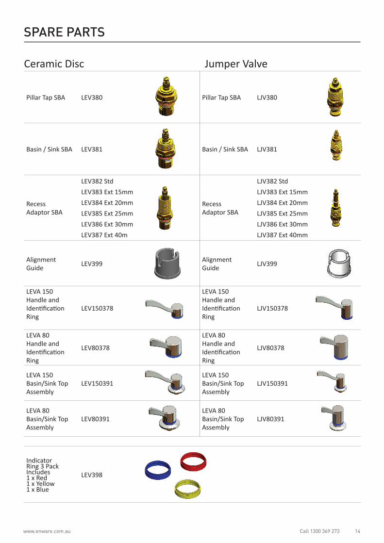
www.enware.com.au Call 1300 369 273 14
Pillar Tap SBA LEV380 Pillar Tap SBA LJV380
Basin / Sink SBA LEV381 Basin / Sink SBA LJV381
Recess Adaptor SBA
LEV382 StdLEV383 Ext 15mmLEV384 Ext 20mmLEV385 Ext 25mmLEV386 Ext 30mmLEV387 Ext 40m
Recess Adaptor SBA
LJV382 StdLJV383 Ext 15mmLJV384 Ext 20mmLJV385 Ext 25mmLJV386 Ext 30mmLJV387 Ext 40mm
Alignment Guide LEV399 Alignment
Guide LJV399
LEVA 150 Handle and Identification Ring
LEV150378
LEVA 150 Handle and Identification Ring
LJV150378
LEVA 80 Handle and Identification Ring
LEV80378
LEVA 80 Handle and Identification Ring
LJV80378
LEVA 150 Basin/Sink Top Assembly
LEV150391LEVA 150 Basin/Sink Top Assembly
LJV150391
LEVA 80 Basin/Sink Top Assembly
LEV80391LEVA 80 Basin/Sink Top Assembly
LJV80391
Indicator Ring 3 Pack Includes 1 x Red 1 x Yellow 1 x Blue
LEV398
SPARE PARTS
Ceramic Disc Jumper Valve

15 Call 1300 369 273 www.enware.com.au
PICTURE 2.1
COMPONENTS Hob Mounted
12
6
8
14
2
5
15
11
1
3
4
7
9
10
13
16
17 18
19
ITEM NO.
PART NUMBER DESCRIPTION QTY.
1 892082 BODY-BASIN RAISED SEAT 2
2 672598 WASHER-RED FIBRE 41X23X1.5MM BSN SPOUT 1
3 672335 NUT - COMPRESSION 1/2 BRS 4
4 672341 OLIVE - NYLON 1/2 INCH 4
5 672051 BACK NUT 1/2 FLANGED BRS LARGE 1
6 893521 TAIL-42MM 1
7 892343 NUT BACK 1 1/4 BRS (50007) 4
8 790783 TOP ASSY LEVA150 JHS (COLD) SINK 1
9 790784 TOP ASSY LEVA150 JHS (HOT) SINK 1
10 672349 ORING BS 008.5 LAB SPINDLE 2
11 760103 BASIN-TEE 190MM 1
12 880701 SPOUT BASIN NO TAIL CACHE LEVA 1
13 673466 AERATOR CACHE TT PCA 7.7L/M 01.5158.0 1
14 673356 ORING BS029 1
15 672597 WASHER-RED FIBRE 45.7X32.5X1.5MM (BSN BD 4
16 882623 DRESS RING BASIN WALL CACHE LEVA 1
17 672017 ALLEN KEY (2.5MM) 1
18 673464 KEY AERATOR CACHE TT 09.9150.0 1
19 693069 TOOL - LEVA HANDLE ALIGNING 1
# Description1 Basin Body2 Red Fibre Washer3 Compression Nut4 Nylon Olive5 Spout Back Nut6 Basin Tail7 Fixing Nut8 Cold Tap Assembly9 Hot Tap Assembly
10 O-rings11 Basin Tee12 Basin Spout13 Aerator Cache14 Basin O-ring15 Fibre Washers16 Basin Spout Dress Ring17 Allen Key18 Aerator Cache Key19 Alignment Guide

www.enware.com.au Call 1300 369 273 16
SERVICING THE SBA OR TAP VALVE
1. Turn water supply off and turn tap handle on to drain water from fitting as much as possible.
2. Remove the handle by unscrewing the discreet pin from the back of the handle. Remove the handle from the assembly
3. Unscrew the wall flange or basin dome from the SBA.
4. Using a suitable spanner unscrew the SBA locknut where fitted.
5. Using a suitable size spanner unscrew the SBA from the tap body ensuring washers, o-rings and seals are removed from tap body.
6. Inspect and rectify/replace parts as per the Trouble Shooting chart and spare parts list. Replace complete SBA if necessary.
PROBLEM CAUSE RECTIFICATION
Taps are dripping water Ceramic discs are wornor Debris is caught in seal
Remove and inspect SBA. Remove debris and/or replace SBA if damaged
SBA lower seal is damaged Replace SBA (recommended) or fit SBA refurbishment kit
Tap seat is damaged Refurbish tap seat using a reseating tool. If necessary - fit reseating kit
Jumper valves are worn or damaged
Replace jumper valve
Water is leaking from spindle O-Ring on spindle Replace O-Ring or SBA
Water is not flowing from tap Water turned off Turn water on
Flow control is blocked by debris Remove tap and wash debris from flow control. Install an inline strainer
Spindle is difficult to turn (jumper valve)
Build up of scale on spindle or gland pack is over tightened.
Spindle needs to be removed, cleaned and regreased. Loosen gland pack nut Replace if badly worn
Handle is wobblyHandle feels loose
Anti-rock spacer is missingScrew adaptor not adjusted correctly
Install anti-rock spacerAdjust screw adaptor – refer to handle fitting instructions
Wall flange does not screw into thread of SBA
Tap bodies are set too far into the wall
Use extended recess spindles
Wall flange does not screw down onto wall surface
Tap bodies are set too far out Use a trouble dome or flange extender
SERVICE AND MAINTENANCE
SBA oring
Ceramic discs SBA bottom seal
TROUBLE SHOOTING

17 Call 1300 369 273 www.enware.com.au
Refer to trouble shooting chart to help determine specific problems
TO RE-ASSEMBLE (Ceramic Disc)
1. Remove the fibre washer and unscrew the threaded locknut from the ceramic cartridge. If necessary screw basin flange back onto basin body and also tighten.
2. Hand tighten the ceramic disc cartridge into the tap body.
3. Using a spanner, or where necessary a tube spanner (do not use multi- grips or pliers) located on the hexagonal flats of the cartridge, turn the cartridge gently until it comes to a firm stop. Do not tighten cartridge by using the spindle. Do not over tighten.
4. Fit the red fibre washer over the spindle/cartridge so it is against the face of the tap body. Now fit the threaded locknut onto the cartridge and screw it up to the face of the tap body, securing the red fibre washer to the tap body.
5. Using a spanner, or where necessary a tube spanner (do not use multi-grips), tighten the locknut firmly. Recommended torque setting is 30Nm.
FITTING DOME AND HANDLE & SKIRT
1. Hand tighten the dress flange onto thread of locknut until it comes to a firm stop.
2. See Installation Instructions - Fitting Handles.
AERATOR (FLOW CONTROLLER)
1. Remove Aerator using Cache aerator key (Part No. 673464) by unscrewing the aerator. If aerator doesn’t come out completely, turn tap on to flush the aerator out. SEE IMAGE 40
2. Inspect and reverse rinse aerator to clear any debris. Replace as necessary.
3. Insert aerator into tip of spout using care to avoid damage to the aerator O-ring by ensuring the aerator is square to the spout outlet and finger tighten half a turn SEE IMAGE 41.
4. Use Cache aerator key to tighten aerator into position. Do not over tighten.
SERVICE AND MAINTENANCE
IMAGE 40 Unscrew aerator using Cache Key Note: Spout shown may look different.
IMAGE 41 When fitting a Cache style aerator use caution to avoid damaging o-ring

www.enware.com.au Call 1300 369 273 18
PRODUCT WARRANTY FOR AUSTRALIA Effective 1 September 2014
Enware Australia Pty Limited (ACN 003 988 314) (“we” or “us”) warrants that this product (also referred to as “our goods”) will be free from all defects in materials and workmanship for 24 months* from the date of purchase. Our liability under this warranty is limited at our option to the repair or replacement of the defective product or part, the cost of repair of the defective product or part or the supply of an equivalent product or part, in each case if we are satisfied the loss or damage was due to a defect in the materials or workmanship of the product or part. All products must be installed in accordance with the manufacturer’s instructions, the PCA, and AS/NZS3500 including any other applicable regulatory requirements.
exceptionsThis warranty does not apply in respect of any damage or loss due to or arising from:
a) Failure by you or any other person to follow any instructions for use (including instructions and directions relating to the handling, storage, installation, fitting, connection, adjustment or repair of the product) published or provided by us;
b) Failure by you or any other person responsible for the fitting, installation or other work on the product to follow or conform to applicable laws, standards and codes (including the AS/NZ 3500 set of Standards, all applicable State and Territory Plumbing Codes, the Plumbing Code of Australia and directions and requirements of local and other statutory authorities); or
c) Any act or circumstance beyond our control including faulty installation or connection, accident, abnormal use, acts of God, damage to buildings, other structures or infrastructure and loss or damage during product transit or transportation.
making a claimTo make a claim under this warranty you must notify us in writing within 7 days of any alleged defect in the product coming to your attention and provide us with proof of your purchase of the product together with a completed Product ServiceRequest form (ENF091), which is available on request from our office or website (see contact details below). All notifications and accompanying forms must be sent to us marked for the attention of the Enware Australia Pty Limited, 9 Endeavour Road, Caringbah NSW 2229. We can also be contacted by telephone (1300 369 273) or by email ([email protected]). Your costs in making a claim under this warranty, including all freight, collection and delivery costs, are to be borne and paid by you. We also reserve the right at our cost to inspect any alleged defect in the product wherever it is located or installed or on our premises.
*Conditional warranty: Jumper Valve Tapware - 2 Years: 1 year parts and labour on the complete assembly then a further 1 year parts only warranty is applicable
Ceramic Disc Cartridge Tapware - 10 Years: 10 Year ceramic disc cartridges – parts only; 1 Year parts and labour on complete assembly
Outlets - 1 Year parts and labour on the complete assembly
other conditionsExcept as provided or referred to in this document, we accept no other or further liability for any damages or loss (including indirect, consequential or economic loss) and whether arising in contract, tort or otherwise. Any benefits available to you under this warranty are in addition to any non-excludable rights or remedies you may have under applicable legislation, including as a “consumer” under the Australian Consumer Law. To that extent you need to be aware that: Our goods come with guarantees that cannot be excluded under the Australian Consumer Law. You are entitled to a replacement or refund for a major failure and for compensation for any other reasonably foreseeable loss or damage. You are also entitled to have the goods repaired or replaced if the goods fail to be of acceptable quality and the failure does not amount to a major failure.