LevelOne GES-1652 - download.level1.comdownload.level1.com/level1/manual/GES-1652_UM_v1.0.pdf ·...
94
Web Smart Switch 1 LevelOne GES-1652 16 GE + 2GE SFP Web Smart Switch User Manual Version 1.0-1109
Transcript of LevelOne GES-1652 - download.level1.comdownload.level1.com/level1/manual/GES-1652_UM_v1.0.pdf ·...
Web Smart Switch
1
LevelOne
GES-1652
16 GE + 2GE SFP
Web Smart Switch
User Manual
Version 1.0-1109

Web Smart Switch
2
FCC Certifications This Equipment has been tested and found to comply with the limits for a Class A digital device, pursuant to part 15 of the FCC Rules. These limits are designed to provide reasonable protection against harmful interference when the equipment is operated in a commercial environment. This equipment generates, uses, and can radiate radio frequency energy and, if not installed and used in accordance with the instruction manual, may cause harmful interference to radio communications. Operation of this equipment in a residential area is likely to cause harmful interference in which case the user will be required to correct the interference at his own expense. This device complies with Part 15 of the FCC Rules. Operation is subject to the following two conditions: (1) this device may not cause harmful interference, and (2) this device must accept any interference received; including interference that may cause undesired operation.
CE Mark Warning This equipment complies with the requirements relating to electromagnetic compatibility, EN 55022 class A for ITE, the essential protection requirement of Council Directive 2004/108/EC on the approximation of the laws of the Member States relating to electromagnetic compatibility. Company has an on-going policy of upgrading its products and it may be possible that information in this document is not up-to-date. Please check with your local distributors for the latest information. No part of this document can be copied or reproduced in any form without written consent from the company. Trademarks: All trade names and trademarks are the properties of their respective companies. Copyright © 2011, All Rights Reserved.
Web Smart Switch
3
Table of Contents
Chapter 1 Introduction to the Web Smart Switch ·················································· 61.1 General Description ················································································ 61.2 The Front Panel ····················································································· 71.3 LEDs Definition ······················································································ 71.4 The Rear Panel ······················································································ 71.5 Installation ····························································································· 9
Chapter 2 Basic Web Management Information ·················································· 112.1 System login ························································································· 112.2 The Graphic User Interface ······································································ 122.3 Logging Out of the Web Configurator ························································· 16
Chapter 3 Web Management Configuration ························································ 173.1 Status ·································································································· 17
3.1.1 System Information ······································································· 173.1.2 Log ···························································································· 183.1.3 Port ···························································································· 20
3.1.3.1 Port Statistics ······································································· 203.1.3.2 Port Counters ······································································ 213.1.3.3 Port Error Disabled ······························································· 233.1.3.4 Bandwidth Utilization ····························································· 23
3.1.4 Trunk Group ················································································· 243.1.5 MAC Address Table ······································································· 25
3.1.5.1 Dynamic Learned ································································· 253.1.5.2 Static MAC ·········································································· 26
3.2 Network ······························································································· 273.2.1 IP Address ··················································································· 273.2.2 IPv6 Address ················································································ 283.2.3 Time ··························································································· 29
3.3 Switching ····························································································· 313.3.1 Port Setting ·················································································· 313.3.2 Port Mirroring ··············································································· 323.3.3 Trunk ·························································································· 33
3.3.3.1 Trunk Group ········································································ 333.3.3.2 LACP ················································································· 35
3.3.4 VLAN ·························································································· 363.3.4.1 VLAN Setting ······································································· 36
Web Smart Switch
4
3.3.4.2 VLAN Port Setting ································································ 373.3.4.3 VLAN Port Mode Setting ························································ 383.3.4.4 VLAN Ingress Filter ······························································· 39
3.3.5 SVLAN ························································································ 393.3.5.1 SVLAN Setting ····································································· 393.3.5.2 SVLAN Member Setting ························································· 403.3.5.3 SVLAN PVID Setting ····························································· 413.3.5.4 SVLAN Service Port ······························································ 41
3.3.6 Bandwidth Control ········································································· 423.3.6.1 Preamble Setting ·································································· 423.3.6.2 Port Rate Setting ·································································· 43
3.3.7 IGMP Snooping ············································································ 453.3.7.1 IGMP Setting ······································································· 453.3.7.2 IGMP VLAN Setting ······························································ 463.3.7.3 Multicast Database ······························································· 473.3.7.4 Router Table ········································································ 48
3.3.8 Jumbo Frame ··············································································· 483.3.9 STP ···························································································· 49
3.3.9.1 STP Global Setting ······························································· 493.3.9.2 STP Port Setting ·································································· 513.3.9.3 MST Configuration ································································ 523.3.9.4 MST Instance Setting ···························································· 543.3.9.5 MST Port Setting ·································································· 54
3.4 Security ······························································································· 563.4.1 Storm Control ··············································································· 563.4.2 MAC Filtering ··············································································· 573.4.3 802.1X ························································································ 58
3.4.3.1 802.1X Setting ····································································· 583.4.3.2 802.1X Port Setting ······························································· 60
3.4.4 Port Security ················································································ 613.4.5 Protected Ports ············································································· 623.4.6 Access ························································································ 62
3.4.6.1 Console ·············································································· 623.4.6.2 Telnet ················································································· 633.4.6.3 SSH ··················································································· 643.4.6.4 HTTP ················································································· 653.4.6.5 HTTPS ··············································································· 65
3.5 ACL ···································································································· 663.5.1 ACL Setting ·················································································· 66
Web Smart Switch
5
3.5.2 ACL Template Setting ····································································· 693.5.3 ACL Index Range Setting ································································ 703.5.4 ACL Policy Setting ········································································· 71
3.6 QoS ···································································································· 713.6.1 Port-based Priority ········································································ 713.6.2 802.1 p- based Priority ··································································· 723.6.3 DSCP - based Priority ···································································· 733.6.4 Priority to Queue Mapping ······························································ 743.6.5 Packet Scheduling ········································································ 763.6.6 Queue Weight Setting ···································································· 763.6.7 Queue Remarking Status ································································ 773.6.8 Queue Remarking Table ································································· 78
3.7 Management ························································································ 793.7.1 SNMP ························································································· 79
3.7.1.1 SNMP Setting ······································································ 793.7.1.2 SNMP Community ································································ 803.7.1.3 SNMP Trap ········································································· 81
3.8 Diagnostics ·························································································· 823.8.1 Ping Test ····················································································· 823.8.2 Ping6 Test ··················································································· 833.8.3 Log Setting ·················································································· 84
3.8.3.1 Local Log ············································································ 843.8.3.2 Remote Log ········································································ 85
3.8.4 Factory Default ············································································· 863.8.5 Reboot Switch ·············································································· 86
3.9 Maintenance ························································································· 873.9.1 Backup Manager ··········································································· 873.9.2 Upgrade Manager ········································································· 893.9.3 Configuration Manager ··································································· 903.9.4 Account Manager ·········································································· 913.9.5 Enable Password ·········································································· 92
Product Specifications ······················································································· 94

6
Chapter 1 Introduction to the Web Smart Switch
1.1 General Description
High Performance
GES-1652 is a powerful, high-performance Gigabit Ethernet switch with 16*10/100/1000Mbps ports and 2*SFP (mini GBIC) ports, providing you a cost-effective, space-saving solution for expanding your network. The gigabit ports can lead you to a real gigabit connection, making you be able to transfer high bandwidth-needed files larger and faster in an easy way. And the four mini gigabit ports allow you to add fiber-optic connectivity for connecting to other network switches to obtain long-distance communication. This device provides the easy management function through the Ethernet Web. The network administrator can configure the status and the port function setting of the device through the Web-Based UI. When installing the auto-discovery management tool helps network managers to search and access those switches on LAN easily. Therefore, network managers can access switches that support auto-discovery on LAN without memorizing IP address.
Smart Features
GES-1652 provides rich features including Link Aggregation, VLANs, IGMP Snooping, Port Trunking, Spanning Tree, Security (Port Security and 802.1x authentication) and other network management to meet the requirements evolving medium and small-sized enterprises. QoS secures the bandwidth for some bandwidth-demanded applications including VoIP or video conference. Additionally, IEEE 802.3az Energy Efficient Ethernet ability is supported to promise operation in Low Power Idle Mode and save power consumption.
Easy Installation and Management
This switch is plug & play and hassle-free in installation. Auto-MDI/MDI-X crossover on all ports eliminates the need for crossover cables for connection to another switch or hub. Auto-Negotiation on each port senses the link speed of a network device and intelligently adjusts for compatibility and optimal performance. This switch also features diagnostic LEDs, which display the status and activities of the LEDs, allowing you to quickly detect and correct problems on the network.
7
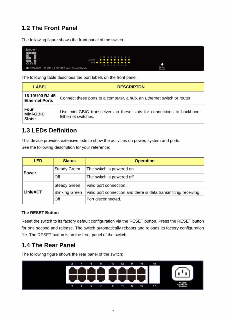
1.2 The Front Panel The following figure shows the front panel of the switch.
The following table describes the port labels on the front panel.
LABEL DESCRIPTON
16 10/100 RJ-45 Ethernet Ports Connect these ports to a computer, a hub, an Ethernet switch or router
Four Mini-GBIC Slots:
Use mini-GBIC transceivers in these slots for connections to backbone Ethernet switches.
1.3 LEDs Definition This device provides extensive leds to show the activities on power, system and ports. See the following description for your reference:
LED Status Operation
Power Steady Green The switch is powered on.
Off The switch is powered off.
Link/ACT Steady Green Valid port connection.
Blinking Green Valid port connection and there is data transmitting/ receiving. Off Port disconnected.
The RESET Button
Reset the switch to its factory default configuration via the RESET button. Press the RESET button for one second and release. The switch automatically reboots and reloads its factory configuration file. The RESET button is on the front panel of the switch.
1.4 The Rear Panel The following figure shows the rear panel of the switch:

Web Smart Switch
8
Power Receptacle To be compatible with the electric service standards around the world, the switch is designed to afford the power supply in the range from 100 to 240 VAC, 50/60 Hz. Please make sure that your outlet standard to be within this range. To power on the switch, please plug the female end of the power cord firmly into the receptacle of the switch and the other end into an electric service outlet. After the power cord installation, please check if the power LED is lit for a normal power status.
9
1.5 Installation This switch can be placed on your desktop directly, or mounted in a rack. Please refer to the instructions for installation. Before installing the switch, we recommend: 1. The switch is placed with appropriate ventilation environment. A minimum 25 mm space
around the unit is recommended. 2. The switch and the relevant components are away from sources of electrical noise such as
radios, transmitters and broadband amplifiers 3. The switch is away from environments beyond recommend moisture
Desktop Installation
1. Install the switch on a level surface that can support the weight of the unit and the relevant components.
2. Plug the switch with the female end of the provided power cord and plug the male end to the power outlet.
Rack-mount Installation
The switch may be standalone, or mounted in a rack. Rack mounting facilitate to an orderly installation when you are going to install series of networking devices. Procedures to Rack-mount the switch: 1. Disconnect all the cables from the switch before continuing. 2. Place the unit the right way up on a hard, flat surface with the front facing you. 3. Locate a mounting bracket over the mounting holes on one side of the unit. 4. Insert the screws and fully tighten with a suitable screwdriver. 5. Repeat the two previous steps for the other side of the unit. 6. Insert the unit into the rack and secure with suitable screws. 7. Reconnect all the cables.
Installing Network Cables
1. Crossover or straight-through cable: All the ports on the switch support Auto-MDI/MDI-X functionality. Both straight-through or crossover cables can be used as the media to connect the switch with PCs as well as other devices like switches, hubs or router.

Web Smart Switch
10
2. Category 3, 4, 5 or 5e, 6 UTP/STP cable: To make a valid connection and obtain the optimal performance, an appropriate cable that corresponds to different transmitting/receiving speed is required. To choose a suitable cable, please refer to the following table.
Media Speed Wiring
10/100/1000 Mbps copper
10 Mbps Category 3,4,5 UTP/STP
100 Mbps Category 5 UTP/STP
1000 Mbps Category 5e, 6 UTP/STP
1000 Mbps Fiber (mini-GBIC required)
1000 Mbps The cable type differs from the mini-GBIC you choose. Please refer to the instruction came with your mini-GBIC.
Web Smart Switch
11
Chapter 2 Basic Web Management Information
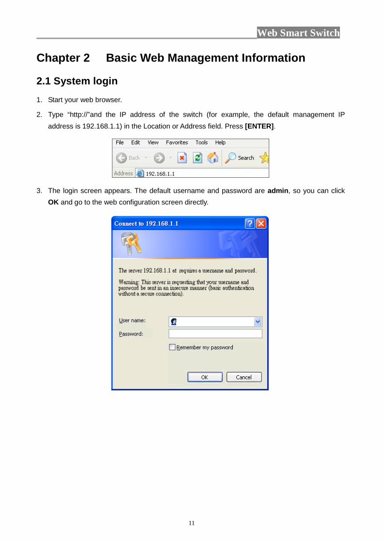
2.1 System login 1. Start your web browser.
2. Type “http://”and the IP address of the switch (for example, the default management IP address is 192.168.1.1) in the Location or Address field. Press [ENTER].
3. The login screen appears. The default username and password are admin, so you can click OK and go to the web configuration screen directly.
Web Smart Switch
12
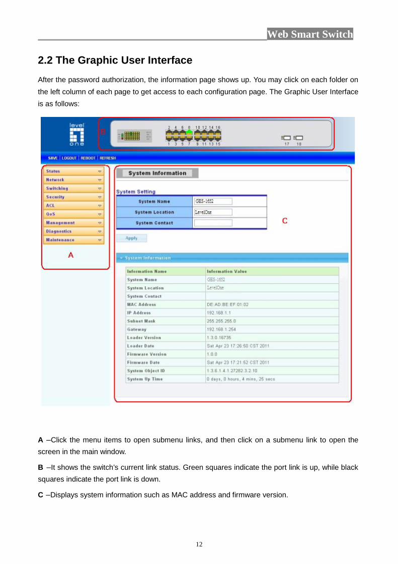
2.2 The Graphic User Interface After the password authorization, the information page shows up. You may click on each folder on the left column of each page to get access to each configuration page. The Graphic User Interface is as follows:
A –Click the menu items to open submenu links, and then click on a submenu link to open the screen in the main window.
B –It shows the switch’s current link status. Green squares indicate the port link is up, while black squares indicate the port link is down.
C –Displays system information such as MAC address and firmware version.
Web Smart Switch
13
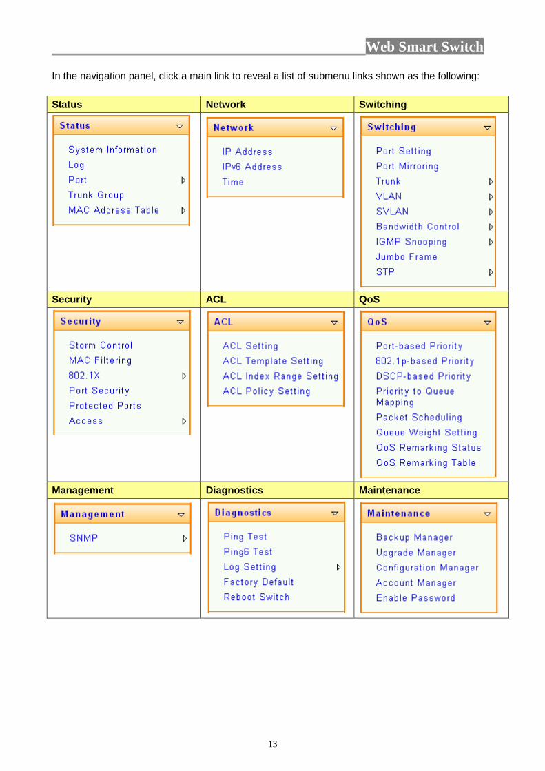
In the navigation panel, click a main link to reveal a list of submenu links shown as the following: Status Network Switching
Security ACL QoS
Management Diagnostics Maintenance
Web Smart Switch
14
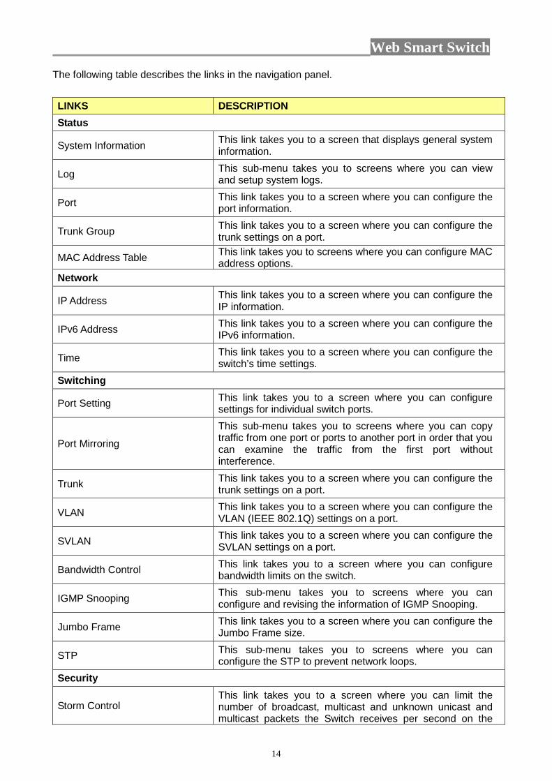
The following table describes the links in the navigation panel. LINKS DESCRIPTION Status
System Information This link takes you to a screen that displays general system information.
Log This sub-menu takes you to screens where you can view and setup system logs.
Port This link takes you to a screen where you can configure the port information.
Trunk Group This link takes you to a screen where you can configure the trunk settings on a port.
MAC Address Table This link takes you to screens where you can configure MAC address options.
Network
IP Address This link takes you to a screen where you can configure the IP information.
IPv6 Address This link takes you to a screen where you can configure the IPv6 information.
Time This link takes you to a screen where you can configure the switch’s time settings.
Switching
Port Setting This link takes you to a screen where you can configure settings for individual switch ports.
Port Mirroring
This sub-menu takes you to screens where you can copy traffic from one port or ports to another port in order that you can examine the traffic from the first port without interference.
Trunk This link takes you to a screen where you can configure the trunk settings on a port.
VLAN This link takes you to a screen where you can configure the VLAN (IEEE 802.1Q) settings on a port.
SVLAN This link takes you to a screen where you can configure the SVLAN settings on a port.
Bandwidth Control This link takes you to a screen where you can configure bandwidth limits on the switch.
IGMP Snooping This sub-menu takes you to screens where you can configure and revising the information of IGMP Snooping.
Jumbo Frame This link takes you to a screen where you can configure the Jumbo Frame size.
STP This sub-menu takes you to screens where you can configure the STP to prevent network loops.
Security
Storm Control This link takes you to a screen where you can limit the number of broadcast, multicast and unknown unicast and multicast packets the Switch receives per second on the
Web Smart Switch
15
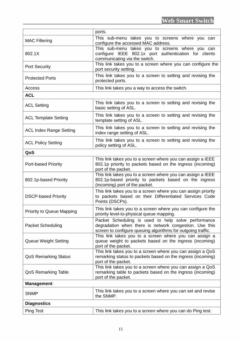
ports.
MAC Filtering This sub-menu takes you to screens where you can configure the accessed MAC address.
802.1X This sub-menu takes you to screens where you can configure IEEE 802.1x port authentication for clients communicating via the switch.
Port Security This link takes you to a screen where you can configure the port security setting.
Protected Ports This link takes you to a screen to setting and revising the protected ports.
Access This link takes you a way to access the switch. ACL
ACL Setting This link takes you to a screen to setting and revising the basic setting of ASL.
ACL Template Setting This link takes you to a screen to setting and revising the template setting of ASL.
ACL Index Range Setting This link takes you to a screen to setting and revising the index range setting of ASL.
ACL Policy Setting This link takes you to a screen to setting and revising the policy setting of ASL.
QoS
Port-based Priority This link takes you to a screen where you can assign a IEEE 802.1p priority to packets based on the ingress (incoming) port of the packet.
802.1p-based Priority This link takes you to a screen where you can assign a IEEE 802.1p-based priority to packets based on the ingress (incoming) port of the packet.
DSCP-based Priority This link takes you to a screen where you can assign priority to packets based on their Differentiated Services Code Points (DSCPs).
Priority to Queue Mapping This link takes you to a screen where you can configure the priority level-to-physical queue mapping.
Packet Scheduling Packet Scheduling is used to help solve performance degradation when there is network congestion. Use this screen to configure queuing algorithms for outgoing traffic.
Queue Weight Setting This link takes you to a screen where you can assign a queue weight to packets based on the ingress (incoming) port of the packet.
QoS Remarking Status This link takes you to a screen where you can assign a QoS remarking status to packets based on the ingress (incoming) port of the packet.
QoS Remarking Table This link takes you to a screen where you can assign a QoS remarking table to packets based on the ingress (incoming) port of the packet.
Management
SNMP This link takes you to a screen where you can set and revise the SNMP.
Diagnostics Ping Test This link takes you to a screen where you can do Ping test.
Web Smart Switch
16
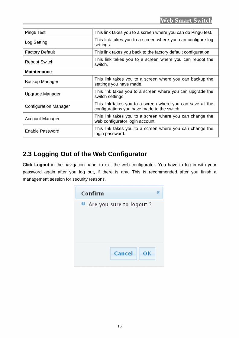
Ping6 Test This link takes you to a screen where you can do Ping6 test.
Log Setting This link takes you to a screen where you can configure log settings.
Factory Default This link takes you back to the factory default configuration.
Reboot Switch This link takes you to a screen where you can reboot the switch.
Maintenance
Backup Manager This link takes you to a screen where you can backup the settings you have made.
Upgrade Manager This link takes you to a screen where you can upgrade the switch settings.
Configuration Manager This link takes you to a screen where you can save all the configurations you have made to the switch.
Account Manager This link takes you to a screen where you can change the web configurator login account.
Enable Password This link takes you to a screen where you can change the login password.
2.3 Logging Out of the Web Configurator Click Logout in the navigation panel to exit the web configurator. You have to log in with your password again after you log out, if there is any. This is recommended after you finish a management session for security reasons.
Web Smart Switch
17
Chapter 3 Web Management Configuration
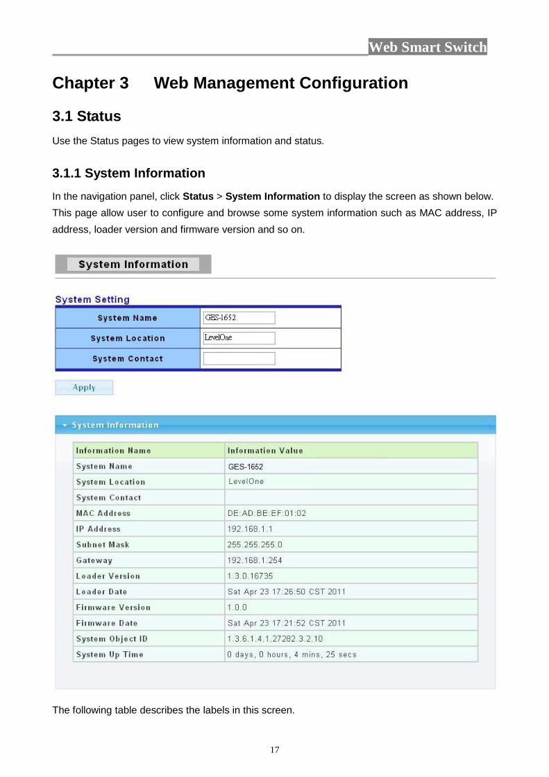
3.1 Status Use the Status pages to view system information and status. 3.1.1 System Information In the navigation panel, click Status > System Information to display the screen as shown below. This page allow user to configure and browse some system information such as MAC address, IP address, loader version and firmware version and so on.
The following table describes the labels in this screen.

Web Smart Switch
18
LABEL DESCRIPTION
System Name This field displays the descriptive name of the switch for identification purposes.
System Location This field displays the system location of the switch.
System Contact This field displays the system contact of the switch.
MAC Address This field refers to the Ethernet MAC (Media Access Control) address of the switch.
IP Address This field displays the IP address of the switch. Subnet Mask This field displays the subnet mask of the switch. Gateway This field displays the IP address of the gateway. Loader Version This field displays the loader version of the switch. Loader Date This field displays the loader date of the switch. Firmware Version This field displays the version number of the switch’s current firmware.
Firmware Date This field displays the switch’s firmware created date. System Object ID This field displays the system object ID of the switch.
System Up Time This field displays the system up time.
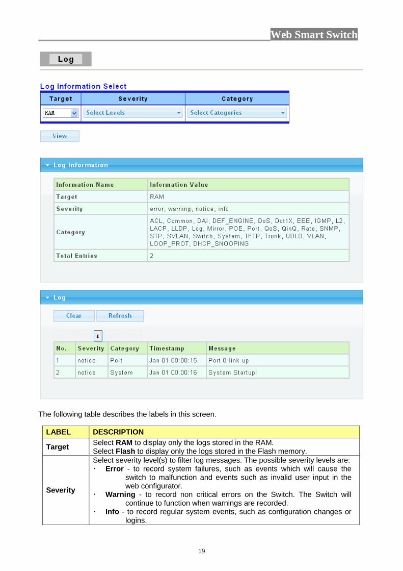
3.1.2 Log Use this screen to display the switch logs. Click Status > Log in the navigation panel to display the screen as shown below.
Web Smart Switch
19
The following table describes the labels in this screen.
LABEL DESCRIPTION
Target Select RAM to display only the logs stored in the RAM. Select Flash to display only the logs stored in the Flash memory.
Severity
Select severity level(s) to filter log messages. The possible severity levels are: Error - to record system failures, such as events which will cause the
switch to malfunction and events such as invalid user input in the web configurator.
Warning - to record non critical errors on the Switch. The Switch will continue to function when warnings are recorded.
Info - to record regular system events, such as configuration changes or logins.
Web Smart Switch
20
Notice- to record the error which need to be noticed.
Category
Select category to filter log messages. The categories are based on software and hardware features of the switch. For example the category MIRROR records events which deal with the Port Mirroring features you set up and the category SYSTEM records events which deal with the overall operation of the switch.
View Click the View button to display the logs according the criteria specified in the fields above.
No. This is the index number for the log entry. Severity This field displays the severity level of the log entry. Category This field displays what category the log entry fits into.
Timestamp This field specifies the time when the switch recorded the log event. The switch resets its internal clock when it is restarted.
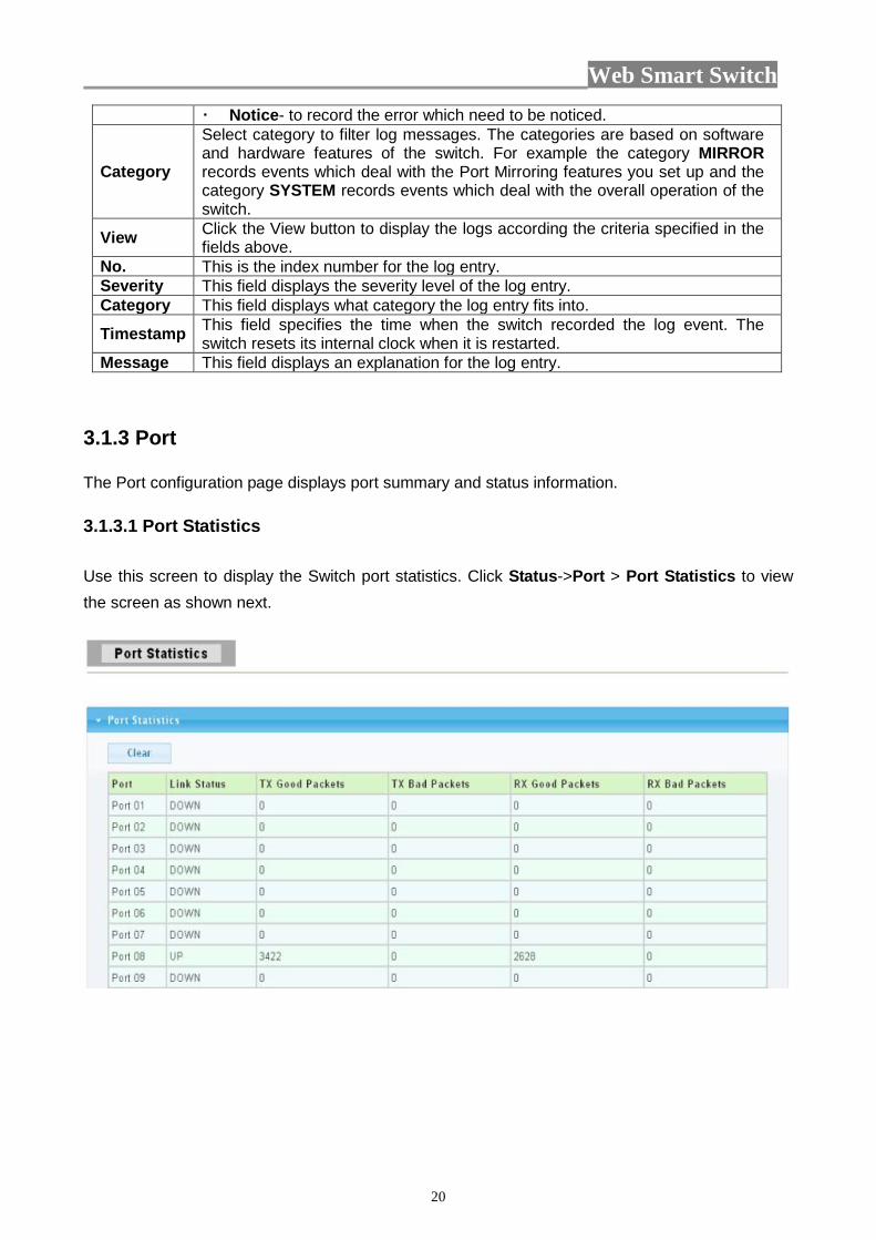
Message This field displays an explanation for the log entry. 3.1.3 Port The Port configuration page displays port summary and status information. 3.1.3.1 Port Statistics Use this screen to display the Switch port statistics. Click Status->Port > Port Statistics to view the screen as shown next.

Web Smart Switch
21
The following table describes the labels in this screen.
LABEL DESCRIPTION Port This identifies the Ethernet port. Link Status This field displays Link Up if the port is currently in use. Otherwise it
displays Link Down. Tx Good Pkt This field shows the number of frames successfully transmitted on this port. Tx Bad Pkt This field shows the number of frames unsuccessfully transmitted on this
port. Rx Good Pkt This field shows the number of frames successfully received on this port. Rx Bad Pkt This field shows the number of frames unsuccessfully received on this port. Clear Click the Clear button to reset the port statistics.
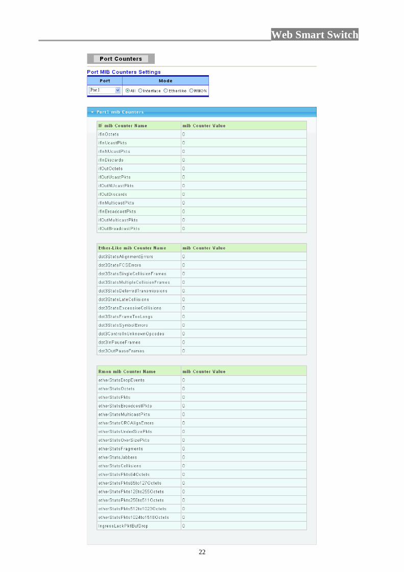
3.1.3.2 Port Counters Click Status->Port > Port Counters to view the screen as shown next. This page displays standard counters on network traffic from the Interface, Etherlike and RMON MIB. Interface and Etherlike counters display errors on the traffic passing through each port. RMON counters provide a total count of different frame types and sizes passing through each port.
Web Smart Switch
22

Web Smart Switch
23
The following table describes the labels in this screen.
LABEL DESCRIPTION Port This identifies the Ethernet port. Mode You have four choices: All, Interface, Etherlike and RMON.
3.1.3.3 Port Error Disabled This page allow user to browse ports which disabled by some protocols such as BPDU Guard, Loopback and UDLD.
The following table describes the labels in this screen.
LABEL DESCRIPTION Port Name This shows the disabled Ethernet port. Error Disabled Reason
Here shows the reasons of these error.
Recover Click this button to enable those error disabled ports. 3.1.3.4 Bandwidth Utilization

Web Smart Switch
24
The following table describes the labels in this screen.
LABEL DESCRIPTION Refresh Period This shows the period interval between last and next refresh. You have
three choices: 2 sec, 5 sec and 10 sec.. IFG You can enable or disable this function.
3.1.4 Trunk Group Click Status > Trunk Group in the navigation panel to view the screen as shown below.
The following table describes the labels in this screen.
Web Smart Switch
25
LABEL DESCRIPTION
Trunk This field displays the trunk to identify a trunk group, that is, one logical link containing multiple ports.
Type This field displays the type of the trunk group: a static trunk or an LACP trunk.
Master port
This field displays which ports are master ports of the trunk. The port with lowest port ID is choosed to be master port of the trunk. To synchronize the settings of trunk member ports, the configuration to trunk master port would be applied to all trunk member ports. Other member ports are slave ports that can not be configured individually in most settings (such as VLAN, port ability and so on.) but to follow the configuration of master port.
Member This field shows the member ports of the trunk. Active/ Passive
If the trunk is an LACP trunk, this field shows the LACP active and passive ports. The LACP active port would send LACP PDU periodically.
Aggregated This field displays the ports that aggregated in a trunk group. A static trunk would be aggregated immediately; an LACP trunk exchanges LACP PDU to link partner to aggregate.
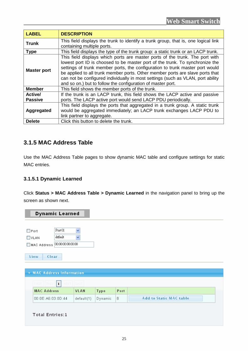
Delete Click this button to delete the trunk. 3.1.5 MAC Address Table Use the MAC Address Table pages to show dynamic MAC table and configure settings for static MAC entries. 3.1.5.1 Dynamic Learned Click Status > MAC Address Table > Dynamic Learned in the navigation panel to bring up the screen as shown next.

Web Smart Switch
26
The following table describes the labels in this screen. LABEL DESCRIPTION
Port Select the port number to show or clear dynamic MAC entries. If not select any port, VLAN and MAC address, the whole dynamic MAC table will be displayed or cleared.
VLAN This is the VLAN group to which the MAC address belongs. Select the VLAN to show or clear dynamic MAC entries. If not select any port, VLAN and MAC address, the whole dynamic MAC table will be displayed or cleared.
MAC Address This field displays the MAC address that will be forwarded. Select the MAC address to show or clear dynamic MAC entries. If not select any port, VLAN and MAC address, the whole dynamic MAC table will be displayed or cleared.
View Click the View button to display the logs according the criteria specified in the fields above.
Clear Click this button to remove any dynamically learned MAC address forwarding entries.
Type This shows whether the MAC address is Dynamic (learned by the Switch) or Static Unicast (manually entered in the Static MAC Forwarding screen).
Port This field displays the port where the MAC address will be forwarded. Add to Static MAC table Click this button to add any port into the static MAC table.
3.1.5.2 Static MAC Click Status > MAC Address Table > Static MAC in the navigation panel to bring up the screen as shown next.
The following table describes the labels in this screen.
Web Smart Switch
27
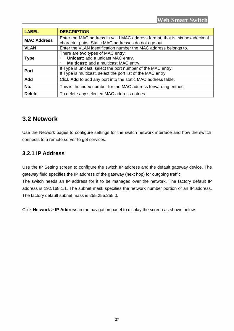
LABEL DESCRIPTION
MAC Address Enter the MAC address in valid MAC address format, that is, six hexadecimal character pairs. Static MAC addresses do not age out.
VLAN Enter the VLAN identification number the MAC address belongs to.
Type There are two types of MAC entry: Unicast: add a unicast MAC entry. Multicast: add a multicast MAC entry.
Port If Type is unicast, select the port number of the MAC entry; If Type is multicast, select the port list of the MAC entry.
Add Click Add to add any port into the static MAC address table. No. This is the index number for the MAC address forwarding entries. Delete To delete any selected MAC address entries.
3.2 Network Use the Network pages to configure settings for the switch network interface and how the switch connects to a remote server to get services. 3.2.1 IP Address Use the IP Setting screen to configure the switch IP address and the default gateway device. The gateway field specifies the IP address of the gateway (next hop) for outgoing traffic. The switch needs an IP address for it to be managed over the network. The factory default IP address is 192.168.1.1. The subnet mask specifies the network number portion of an IP address. The factory default subnet mask is 255.255.255.0.
Click Network > IP Address in the navigation panel to display the screen as shown below.

Web Smart Switch
28
The following table describes the labels in this screen.
LABEL DESCRIPTION Mode Select Static from the drop-down box if you don’t have a DHCP server or if
you wish to assign static IP address information to the switch. You need to fill in the following fields when you select this option. Select DHCP option if you have a DHCP server that can assign the switch an IP address, subnet mask and a gateway IP address automatically.
IP Address Enter the IP address of your switch in dotted decimal notation for example 192.168.1.1. If static mode is enabled, enter IP address in this field.
Subnet Mask Enter the IP subnet mask of your switch in dotted decimal notation for example 255.255.255.0. If static mode is enabled, enter subnet mask in this field.
Gateway Enter the IP address of the gateway in dotted decimal notation. If static mode is enabled, enter gateway address in this field.
Apply Click Apply to save your changes to the switch. 3.2.2 IPv6 Address
Click Network> IPv6 Address in the navigation panel to display the screen as shown below.

Web Smart Switch
29
The following table describes the labels in this screen.
LABEL DESCRIPTION Auto Configuration
Select Enable or Disable this function.
IPv6 Address Enter the IPv6 address of your switch. If auto configuration mode is disabled, enter IPv6 address in this field.
Gateway Enter the IP address of the gateway in dotted decimal notation. If auto configuration mode is disabled, enter IPv6 gateway address in this field.
Apply Click Apply to save your changes to the switch. Auto Configuration
It displays whether the auto configuration function is opened or not.
IPv6 In Use Address
It displays the in use address information of IPv6.
IPv6 In Use Router
It displays the in use router information of IPv6.
IPv6 Static Address
It displays the static address of IPv6.
IPv6 Static router
It displays the static router of IPv6.
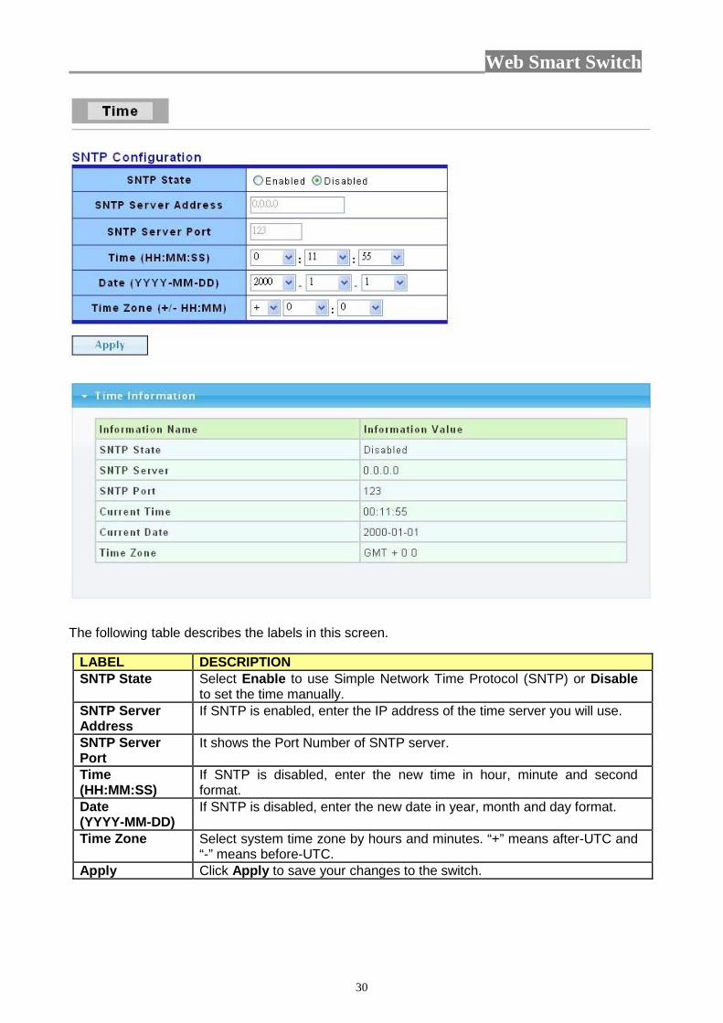
3.2.3 Time Click Network> Time in the navigation panel to display the screen as shown below.
Web Smart Switch
30
The following table describes the labels in this screen.
LABEL DESCRIPTION SNTP State Select Enable to use Simple Network Time Protocol (SNTP) or Disable
to set the time manually. SNTP Server Address
If SNTP is enabled, enter the IP address of the time server you will use.
SNTP Server Port
It shows the Port Number of SNTP server.
Time (HH:MM:SS)
If SNTP is disabled, enter the new time in hour, minute and second format.
Date (YYYY-MM-DD)
If SNTP is disabled, enter the new date in year, month and day format.
Time Zone Select system time zone by hours and minutes. “+” means after-UTC and “-” means before-UTC.
Apply Click Apply to save your changes to the switch.

Web Smart Switch
31
3.3 Switching Use the Switching pages to configure settings for the switch ports, trunk and other switch features. 3.3.1 Port Setting This page allow user to configure switch port settings and show port current status. Click Switching > Port Setting in the navigation panel to display the screen as shown below.
The following table describes the labels in this screen.
LABEL DESCRIPTION Port Select Select the port(s) from the list box that you will change the port settings
for. Name It allows you to give a description for the port. Enabled Select Enable from the drop-down box to enable a port. The factory
default for all ports is enabled. A port must be enabled for data transmission to occur. Select Disable to not use a port.
Speed Port speed capabilities: Auto: Auto speed with all capabilities. Auto-10M: Auto speed with 10M ability only. Auto-100M: Auto speed with 100M ability only. Auto-1000M: Auto speed with 1000M ability only. Auto-10/100M: Auto speed with 10/100M ability. 10M: Force speed with 10M ability. 100M: Force speed with 100M ability. 1000M: Force speed with 1000M ability. Selecting Auto (auto-negotiation) allows one port to negotiate with a peer port automatically to obtain the connection speed and duplex mode that
Web Smart Switch
32
both ends support. When auto-negotiation is turned on, a port on the switch negotiates with the peer automatically to determine the connection speed and duplex mode. If the peer port does not support auto-negotiation or turns off this feature, the switch determines the connection speed by detecting the signal on the cable and using half duplex mode. When the switch’s auto-negotiation is turned off, a port uses the pre-configured speed and duplex mode when making a connection, thus requiring you to make sure that the settings of the peer port are the same in order to connect.
Duplex Port duplex capabilities: Auto: Auto duplex with all capabilities. Half: Auto speed with 10M ability only. Full: Auto speed with 100M ability only.
Flow Control A concentration of traffic on a port decreases port bandwidth and overflows buffer memory causing packet discards and frame losses. Flow Control is used to regulate transmission of signals to match the bandwidth of the receiving port. The switch uses IEEE802.3x flow control in full duplex mode and backpressure flow control in half duplex mode. IEEE802.3x flow control is used in full duplex mode to send a pause signal to the sending port, causing it to temporarily stop sending signals when the receiving port memory buffers fill. Back Pressure flow control is typically used in half duplex mode to send a "collision" signal to the sending port (mimicking a state of packet collision) causing the sending port to temporarily stop sending signals and resend later. Select “Enabled” to enable it. Or select “Disabled” to disable it.
Apply Click Apply to save your changes to the switch. Flow Control Config
The Config column displays if Flow Control has been configured to be turned On or Off for the port.
Flow Control Status
The column displays the port’s current Flow Control status.
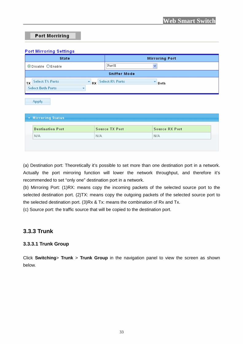
3.3.2 Port Mirroring The Mirror function copies all the packets that are transmitted by the source port to the destination port. It allows administrators to analyze and monitor the traffic of the monitored ports. The Mirror Configuration steps are as follows: 1. Choose “enable ” or “disable” this function in “State” column 2. Select those ports that are going to be monitored by marking the checkboxes in “Monitoring Port” column. 3. Click the “TX” or “RX” or “Both” in the drop list of “Sniffer Mode” column. Select the packet types that are going to be monitored (transferred or received packets or both). 4. Click “Apply” to activate.
Web Smart Switch
33
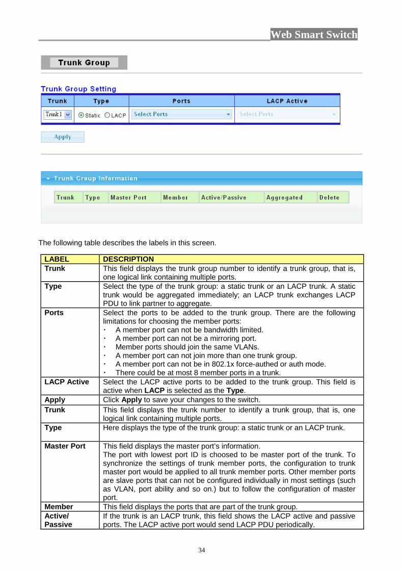
(a) Destination port: Theoretically it’s possible to set more than one destination port in a network. Actually the port mirroring function will lower the network throughput, and therefore it’s recommended to set “only one” destination port in a network. (b) Mirroring Port: (1)RX: means copy the incoming packets of the selected source port to the selected destination port. (2)TX: means copy the outgoing packets of the selected source port to the selected destination port. (3)Rx & Tx: means the combination of Rx and Tx. (c) Source port: the traffic source that will be copied to the destination port. 3.3.3 Trunk 3.3.3.1 Trunk Group Click Switching> Trunk > Trunk Group in the navigation panel to view the screen as shown below.
Web Smart Switch
34
The following table describes the labels in this screen.
LABEL DESCRIPTION Trunk This field displays the trunk group number to identify a trunk group, that is,
one logical link containing multiple ports. Type Select the type of the trunk group: a static trunk or an LACP trunk. A static
trunk would be aggregated immediately; an LACP trunk exchanges LACP PDU to link partner to aggregate.
Ports Select the ports to be added to the trunk group. There are the following limitations for choosing the member ports: A member port can not be bandwidth limited. A member port can not be a mirroring port. Member ports should join the same VLANs. A member port can not join more than one trunk group. A member port can not be in 802.1x force-authed or auth mode. There could be at most 8 member ports in a trunk.
LACP Active Select the LACP active ports to be added to the trunk group. This field is active when LACP is selected as the Type.
Apply Click Apply to save your changes to the switch. Trunk This field displays the trunk number to identify a trunk group, that is, one
logical link containing multiple ports. Type Here displays the type of the trunk group: a static trunk or an LACP trunk.
Master Port This field displays the master port’s information. The port with lowest port ID is choosed to be master port of the trunk. To synchronize the settings of trunk member ports, the configuration to trunk master port would be applied to all trunk member ports. Other member ports are slave ports that can not be configured individually in most settings (such as VLAN, port ability and so on.) but to follow the configuration of master port.
Member This field displays the ports that are part of the trunk group. Active/ Passive
If the trunk is an LACP trunk, this field shows the LACP active and passive ports. The LACP active port would send LACP PDU periodically.
Web Smart Switch
35
Aggregated This field displays the ports that aggregated in a trunk group. A static trunk would be aggregated immediately; an LACP trunk exchanges LACP PDU to link partner to aggregate.
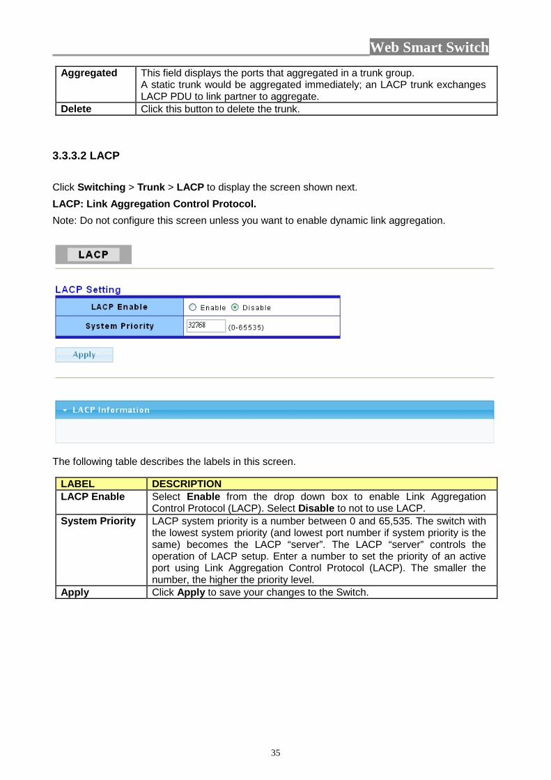
Delete Click this button to delete the trunk. 3.3.3.2 LACP Click Switching > Trunk > LACP to display the screen shown next. LACP: Link Aggregation Control Protocol. Note: Do not configure this screen unless you want to enable dynamic link aggregation.
The following table describes the labels in this screen.
LABEL DESCRIPTION LACP Enable Select Enable from the drop down box to enable Link Aggregation
Control Protocol (LACP). Select Disable to not to use LACP. System Priority LACP system priority is a number between 0 and 65,535. The switch with
the lowest system priority (and lowest port number if system priority is the same) becomes the LACP “server”. The LACP “server” controls the operation of LACP setup. Enter a number to set the priority of an active port using Link Aggregation Control Protocol (LACP). The smaller the number, the higher the priority level.
Apply Click Apply to save your changes to the Switch.

Web Smart Switch
36
3.3.4 VLAN Each VLAN in a network has a associated VLAN ID, which displays in the IEEE 802.1Q tag in the L2 header of packets transmitted on a VLAN. 3.3.4.1 VLAN Setting This page allow user to add, edit or delete VLAN settings. Click Switching > VLAN > VLAN Setting to access this screen below to configure and view VLAN parameters for the switch.
The following table describes the related labels in this screen.
LABEL DESCRIPTION VLAN ID A unique number (between 1 and 4094) that identifies a particular VLAN. VLAN Name A 32-character alphanumeric name associated with a VLAN ID. The VLAN
Name is intended to make user-defined VLANs easier to identify and remember.
Untagged Ports Select
Select Untagged to make the port a permanent member of this VLAN group. All outgoing frames will be transmitted without a VLAN Group ID tag.
Tagged Ports Select
Select Tagged to make the port a permanent member of this VLAN group. All outgoing frames will be transmitted with the VLAN Group ID tag.
Add Click Add to save your changes to the Switch. VLAN ID This field displays the unique identification number of the VLAN group. VLAN Name This field displays the descriptive name for this VLAN group. Untagged Ports
This field displays all the ports that will transmit outgoing frames without a VLAN group ID tag.
Tagged Ports This field displays all the ports that will transmit outgoing frames with a VLAN group ID tag.
Modify Click Edit to modify the tagged and untagged ports.
Web Smart Switch
37
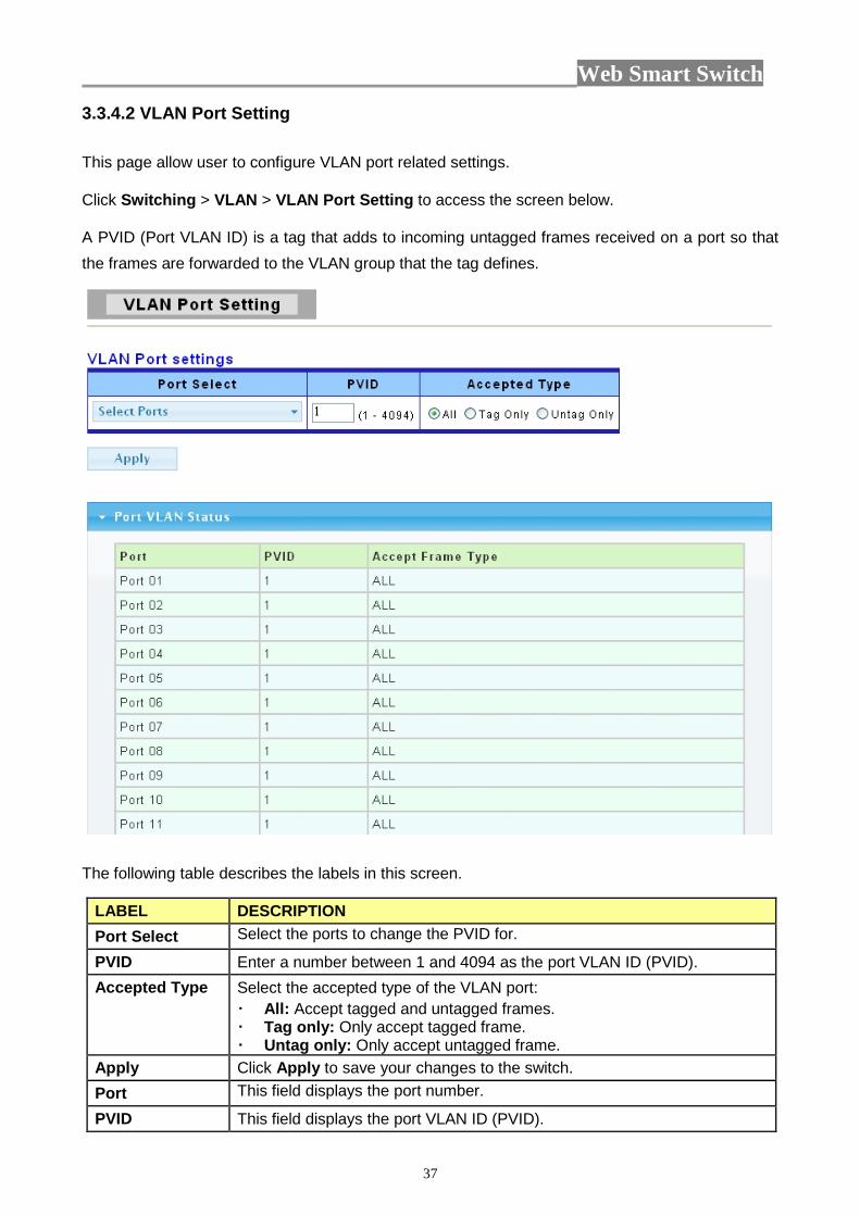
3.3.4.2 VLAN Port Setting This page allow user to configure VLAN port related settings. Click Switching > VLAN > VLAN Port Setting to access the screen below. A PVID (Port VLAN ID) is a tag that adds to incoming untagged frames received on a port so that the frames are forwarded to the VLAN group that the tag defines.
The following table describes the labels in this screen.
LABEL DESCRIPTION Port Select Select the ports to change the PVID for.
PVID Enter a number between 1 and 4094 as the port VLAN ID (PVID). Accepted Type Select the accepted type of the VLAN port:
All: Accept tagged and untagged frames. Tag only: Only accept tagged frame. Untag only: Only accept untagged frame.
Apply Click Apply to save your changes to the switch. Port This field displays the port number.
PVID This field displays the port VLAN ID (PVID).
Web Smart Switch
38
Accepted Frame Type
This field displays the accepted frame type of the VLAN port.
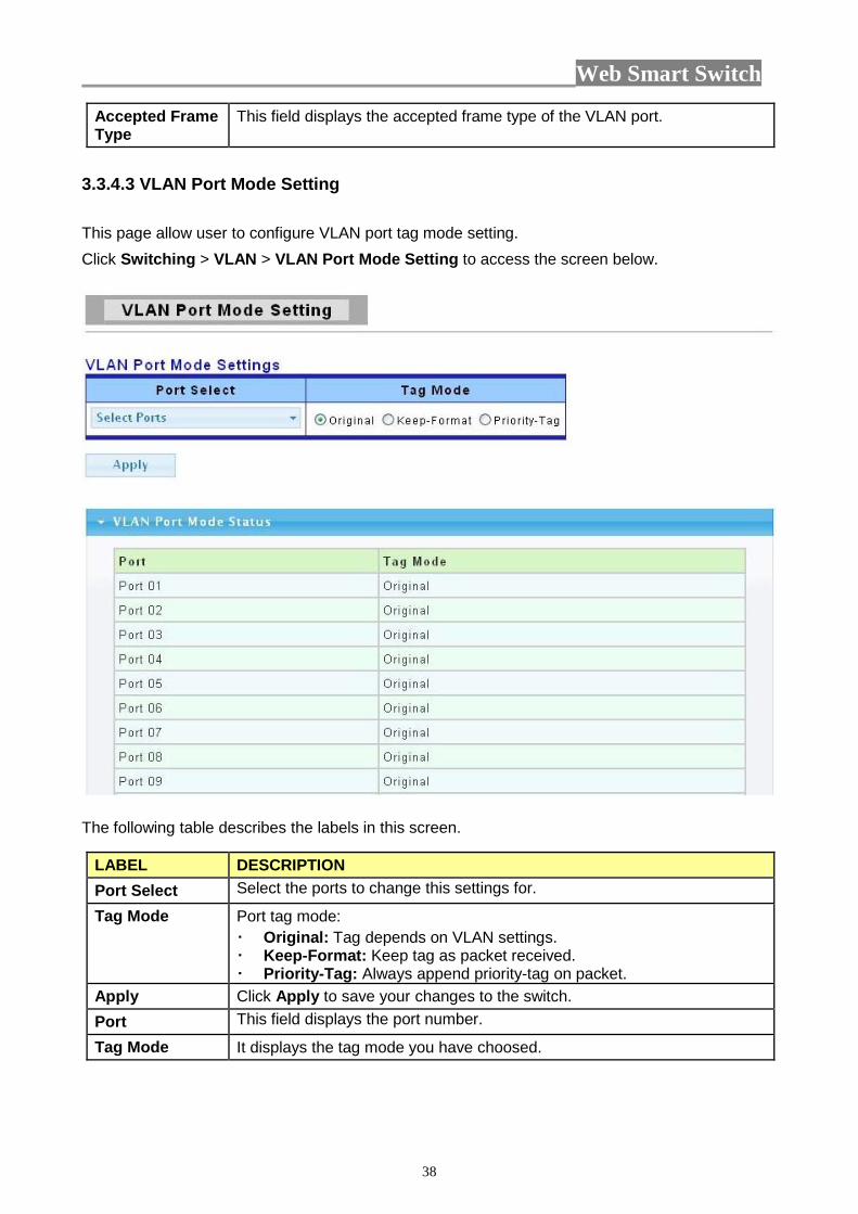
3.3.4.3 VLAN Port Mode Setting This page allow user to configure VLAN port tag mode setting. Click Switching > VLAN > VLAN Port Mode Setting to access the screen below.
The following table describes the labels in this screen.
LABEL DESCRIPTION Port Select Select the ports to change this settings for.
Tag Mode Port tag mode: Original: Tag depends on VLAN settings. Keep-Format: Keep tag as packet received. Priority-Tag: Always append priority-tag on packet.
Apply Click Apply to save your changes to the switch. Port This field displays the port number.
Tag Mode It displays the tag mode you have choosed.
Web Smart Switch
39
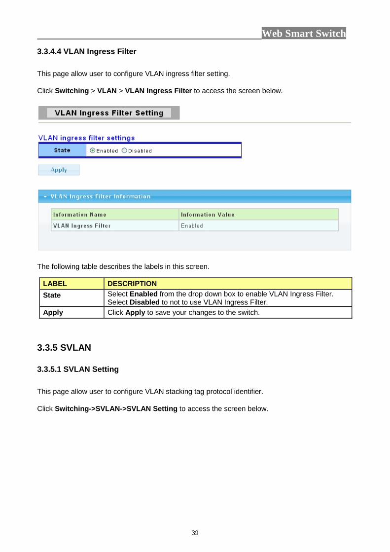
3.3.4.4 VLAN Ingress Filter This page allow user to configure VLAN ingress filter setting. Click Switching > VLAN > VLAN Ingress Filter to access the screen below.
The following table describes the labels in this screen.
LABEL DESCRIPTION State Select Enabled from the drop down box to enable VLAN Ingress Filter.
Select Disabled to not to use VLAN Ingress Filter. Apply Click Apply to save your changes to the switch.
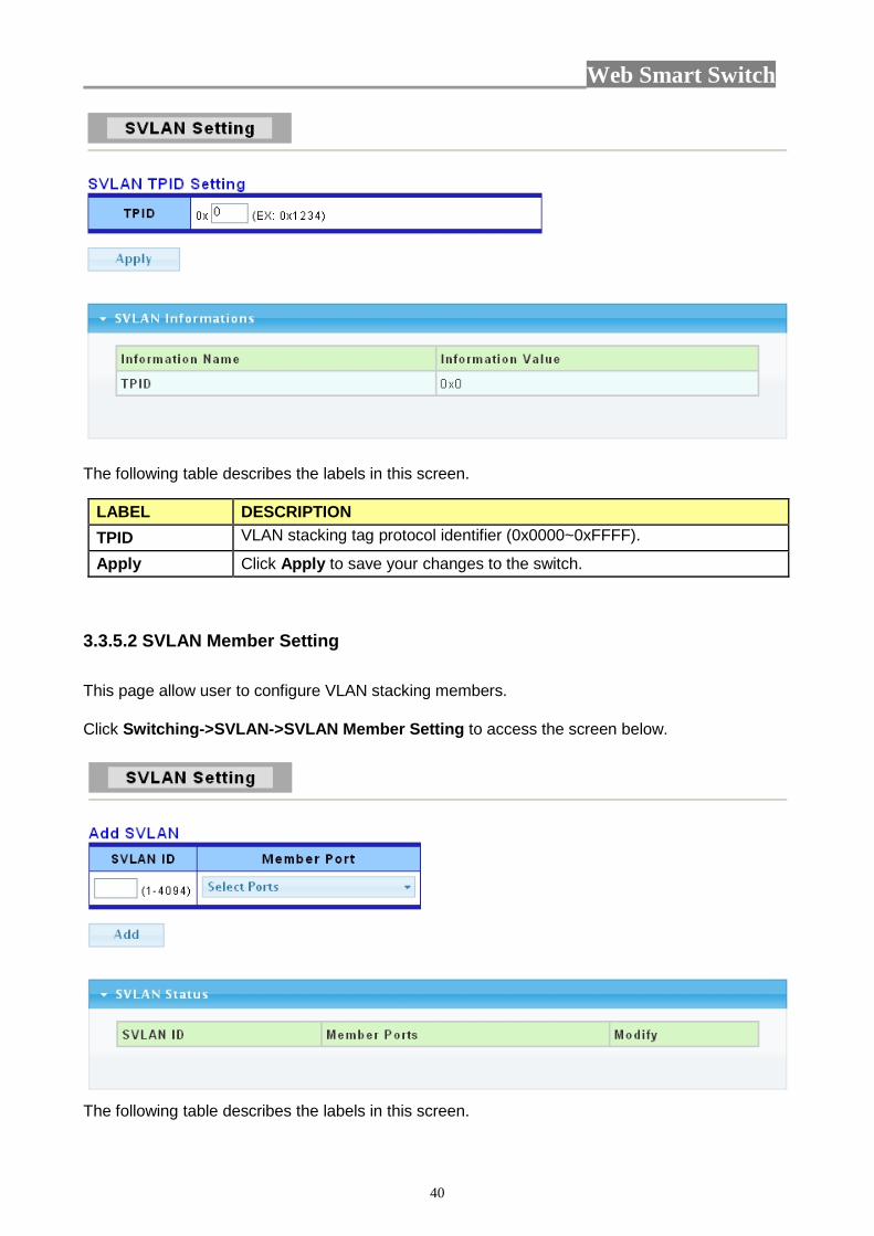
3.3.5 SVLAN 3.3.5.1 SVLAN Setting This page allow user to configure VLAN stacking tag protocol identifier. Click Switching->SVLAN->SVLAN Setting to access the screen below.
Web Smart Switch
40
The following table describes the labels in this screen.
LABEL DESCRIPTION TPID VLAN stacking tag protocol identifier (0x0000~0xFFFF).
Apply Click Apply to save your changes to the switch.
3.3.5.2 SVLAN Member Setting This page allow user to configure VLAN stacking members. Click Switching->SVLAN->SVLAN Member Setting to access the screen below.
The following table describes the labels in this screen.

Web Smart Switch
41
LABEL DESCRIPTION SVLAN ID Stacking VLAN ID.
Member Port Select one or multiple ports as member ports of the SVLAN.
Add Click Add to add any member port into the SVLAN .
3.3.5.3 SVLAN PVID Setting This page allow user to add or set port VLAN stacking entry in the VLAN stacking table. Click Switching->SVLAN->SVLAN PVID Setting to access the screen below.
The following table describes the labels in this screen.
LABEL DESCRIPTION Port Select the port(s) to configure the SVLAN PVID settings for.
PVID Set VLAN ID for selected ports.
Apply Click Apply to save your changes to the switch.
3.3.5.4 SVLAN Service Port This page allow user to configure VLAN stacking-aware ports.

Web Smart Switch
42
Click Switching->SVLAN->SVLAN Service Port to access the screen below.
The following table describes the labels in this screen.
LABEL DESCRIPTION Port Select the port(s) to configure this settings for.
Enabled Set VLAN stacking aware state: Enabled: Set as VLAN stacking aware. Disabled: Set as VLAN stacking unaware.
Apply Click Apply to save your changes to the switch.
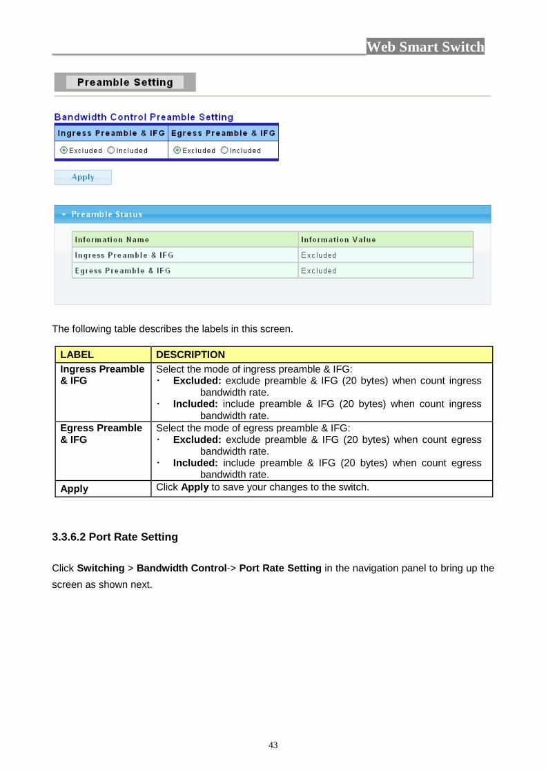
3.3.6 Bandwidth Control 3.3.6.1 Preamble Setting Click Switching > Bandwidth Control->Preamble Setting in the navigation panel to bring up the screen as shown next.
Web Smart Switch
43
The following table describes the labels in this screen.
LABEL DESCRIPTION Ingress Preamble & IFG
Select the mode of ingress preamble & IFG: Excluded: exclude preamble & IFG (20 bytes) when count ingress
bandwidth rate. Included: include preamble & IFG (20 bytes) when count ingress
bandwidth rate. Egress Preamble & IFG
Select the mode of egress preamble & IFG: Excluded: exclude preamble & IFG (20 bytes) when count egress
bandwidth rate. Included: include preamble & IFG (20 bytes) when count egress
bandwidth rate. Apply Click Apply to save your changes to the switch.
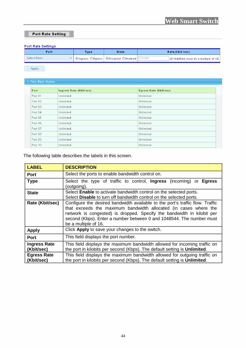
3.3.6.2 Port Rate Setting Click Switching > Bandwidth Control-> Port Rate Setting in the navigation panel to bring up the screen as shown next.
Web Smart Switch
44
The following table describes the labels in this screen.
LABEL DESCRIPTION Port Select the ports to enable bandwidth control on. Type Select the type of traffic to control, Ingress (incoming) or Egress
(outgoing). State Select Enable to activate bandwidth control on the selected ports.
Select Disable to turn off bandwidth control on the selected ports. Rate (Kbit/sec) Configure the desired bandwidth available to the port’s traffic flow. Traffic
that exceeds the maximum bandwidth allocated (in cases where the network is congested) is dropped. Specify the bandwidth in kilobit per second (Kbps). Enter a number between 0 and 1048544. The number must be a multiple of 16.
Apply Click Apply to save your changes to the switch.
Port This field displays the port number. Ingress Rate (Kbit/sec)
This field displays the maximum bandwidth allowed for incoming traffic on the port in kilobits per second (Kbps). The default setting is Unlimited.
Egress Rate (Kbit/sec)
This field displays the maximum bandwidth allowed for outgoing traffic on the port in kilobits per second (Kbps). The default setting is Unlimited.

Web Smart Switch
45
3.3.7 IGMP Snooping Use the Switching pages to configure settings for the switch network interface and how the switch connects to a remote server to get services. 3.3.7.1 IGMP Setting Click Switching > IGMP Snooping > IGMP Setting to access the screen below.
The following table describes the labels in this screen.
Web Smart Switch
46
LABEL DESCRIPTION IGMP Snooping Select Enable from the drop down box to enable IGMP Snooping. Select
Disable to not to use IGMP Snooping. When enabled, it simply monitors the IGMP packets passing through it, picks out the group registration information, and configures the multicast filters accordingly.
Fastleave Select Enable from the drop down box to enable IGMP Fast-Leave. Select Disable to not to use IGMP Fast-Leave.
Unknown Multicast Action
Unknown multicast message to the switch. Enable Drop will throw away the unknown multicast message. Enable Flood will flood the packets.
Query Interval The query interval is the amount of time in seconds between IGMP General Query messages sent by the router (if the router is the querier on this subnet). You can also click the scroll arrows to select a new setting. The default query interval is 125 seconds.
Response Time The time a generic system or functional unit takes to react to a given input. The default value is 10s.
Router Timeout Save the time of the router port timer in the form. The default value is 125s.
Last Member Query Interval
The interval that Querier-switch sends Group-Specific Queriers when it receives a Leave Group message for a group.
Robustness Variable The robustness variable is a way of indicating how susceptible the
subnet is to lost packets. IGMP can recover from robustness variable minus 1 lost IGMP packets. You can also click the scroll arrows to select a new setting. The robustness variable should be set to a value of 2 or greater. The default robustness variable value is 2.
Apply Click Apply to save your changes to the switch.
Host Timeout Save the timer related the host and its member. The default value is 260s.
Querier Election Time It displays the querier election time.
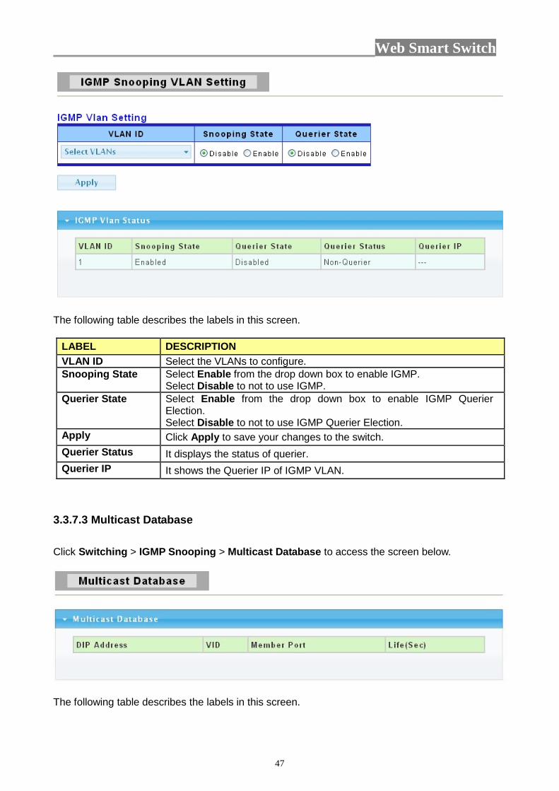
3.3.7.2 IGMP VLAN Setting Click Switching > IGMP Snooping > IGMP VLAN Setting to access the screen below.
Web Smart Switch
47
The following table describes the labels in this screen.
LABEL DESCRIPTION VLAN ID Select the VLANs to configure. Snooping State Select Enable from the drop down box to enable IGMP.
Select Disable to not to use IGMP. Querier State Select Enable from the drop down box to enable IGMP Querier
Election. Select Disable to not to use IGMP Querier Election.
Apply Click Apply to save your changes to the switch. Querier Status It displays the status of querier. Querier IP It shows the Querier IP of IGMP VLAN.
3.3.7.3 Multicast Database Click Switching > IGMP Snooping > Multicast Database to access the screen below.
The following table describes the labels in this screen.

Web Smart Switch
48
LABEL DESCRIPTION DIP Address This field displays IP address of this group. VID This field displays ID of configured VLAN (1~4094).
Member Port This field displays the ports that selected in the group address.
Life(Sec) This field displays the life time of this group.
3.3.7.4 Router Table Click Switching > IGMP Snooping > Router Table to access the screen below.
The following table describes the labels in this screen.
LABEL DESCRIPTION VID The VLAN ID that has router port.
Port Router port (i.e. the port ID where IGMP Query message received ).
Expiry Time(Sec) This field displays the expiry time of the router port.
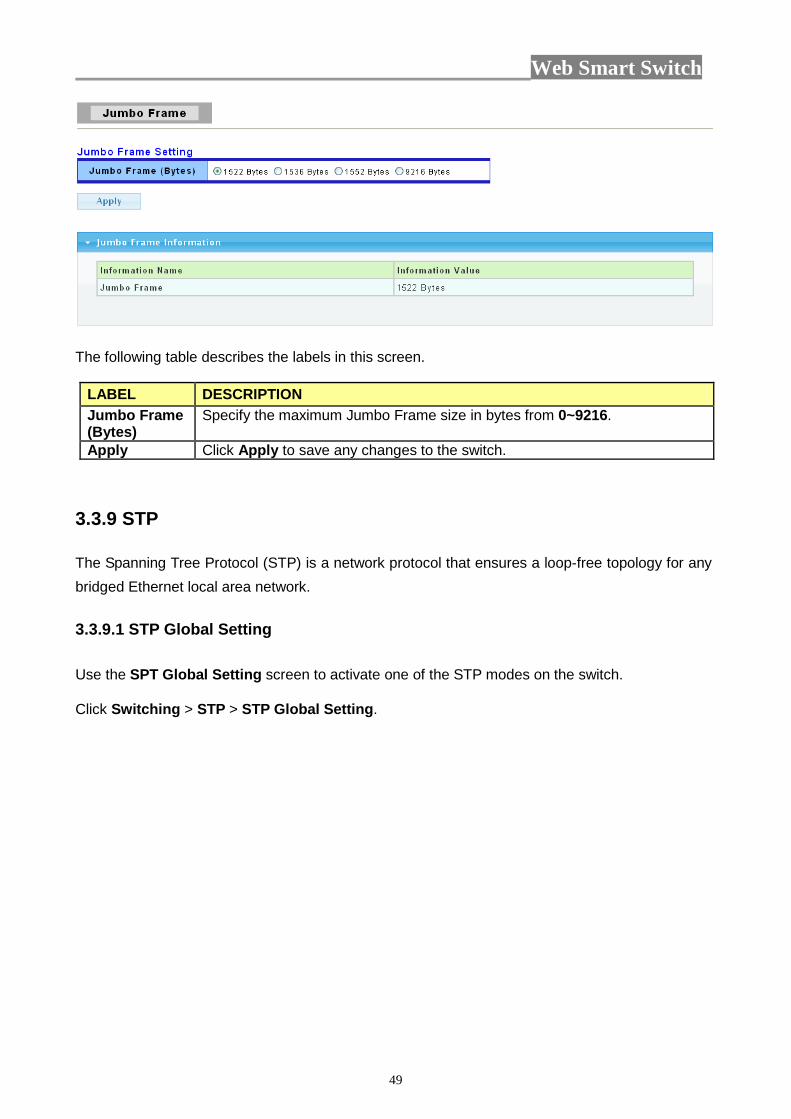
3.3.8 Jumbo Frame This page allow user to configure switch port jumbo frame settings. Click Switching > Jumbo Frame in the navigation panel to bring up the screen as shown next.
Web Smart Switch
49
The following table describes the labels in this screen.
LABEL DESCRIPTION Jumbo Frame (Bytes)
Specify the maximum Jumbo Frame size in bytes from 0~9216.
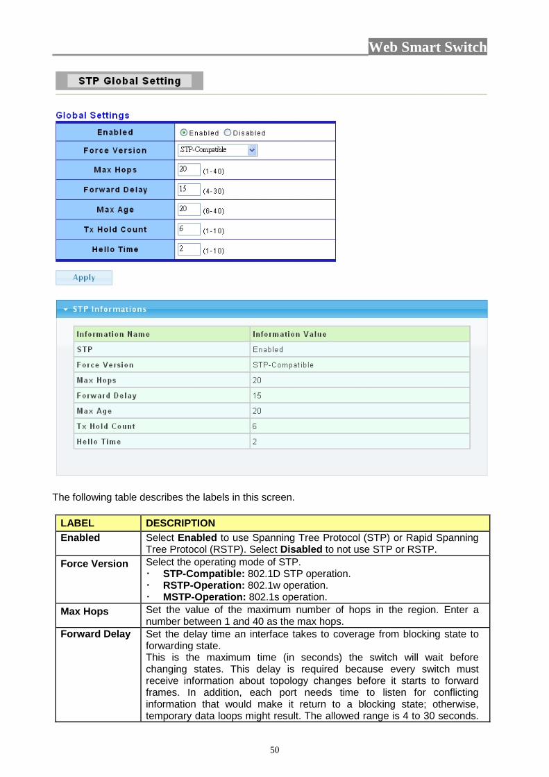
Apply Click Apply to save any changes to the switch. 3.3.9 STP The Spanning Tree Protocol (STP) is a network protocol that ensures a loop-free topology for any bridged Ethernet local area network. 3.3.9.1 STP Global Setting Use the SPT Global Setting screen to activate one of the STP modes on the switch. Click Switching > STP > STP Global Setting.
Web Smart Switch
50
The following table describes the labels in this screen.
LABEL DESCRIPTION Enabled Select Enabled to use Spanning Tree Protocol (STP) or Rapid Spanning
Tree Protocol (RSTP). Select Disabled to not use STP or RSTP. Force Version Select the operating mode of STP.
STP-Compatible: 802.1D STP operation. RSTP-Operation: 802.1w operation. MSTP-Operation: 802.1s operation.
Max Hops Set the value of the maximum number of hops in the region. Enter a number between 1 and 40 as the max hops.
Forward Delay Set the delay time an interface takes to coverage from blocking state to forwarding state. This is the maximum time (in seconds) the switch will wait before changing states. This delay is required because every switch must receive information about topology changes before it starts to forward frames. In addition, each port needs time to listen for conflicting information that would make it return to a blocking state; otherwise, temporary data loops might result. The allowed range is 4 to 30 seconds.
Web Smart Switch
51
As a general rule: Note: 2 * (Forward Delay – 1) >= Max Age >= 2 * (Hello Time + 1)
Max Age Set the time any switch should wait before trying to change the STP topology after unhearing Hello BPDU.
Tx Hold Count Set the Transmit Hold Count used to limit BPDU transmission rate. Enter a number between 1 and 10 as the Tx hold count.
Hello Time Set the interval between periodic transmissions of BPDU by Designated Ports. This is the time interval (in seconds) at which the root switch transmits a configuration message. The root bridge determines Hello Time, Max Age and Forward Delay.
Apply Click Apply to save your changes to the switch.
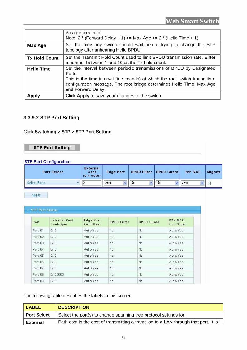
3.3.9.2 STP Port Setting Click Switching > STP > STP Port Setting.
The following table describes the labels in this screen. LABEL DESCRIPTION Port Select Select the port(s) to change spanning tree protocol settings for. External Path cost is the cost of transmitting a frame on to a LAN through that port. It is
Web Smart Switch
52
Cost recommended to assign this value according to the speed of the bridge. The slower the media, the higher the cost. Entering 0 means the switch will automatically assign a value.
Edge Port Set the edge port configuration: No: Force to false state ( as link to a bridge). Yes: Force to true state ( as link to a host). Auto: Auto detect.
BPDU Filter Set the BPDU Filter configuration: No: Disable BPDU Filter function. Yes: Enable BPDU Filter function. To avoid transmitting BPDU from the specified ports
BPDU Guard
Set the BPDU Guard configuration: No: Disable BPDU Guard function. Yes: Enable BPDU Guard function. To drop directly the received BPDU from the specified ports
P2P MAC Set the Point-to-Point port configuration: No: Force to false state. Yes: Force to true state. Auto: Auto detect ( according to duplex).
Migrate Click the square choice box to enable this function. Force to try to use the new MST/RST BPDUs, and hence to test the hypothesis that all legacy systems that do not understand the new BPDU formats have been removed from the LAN segment on the port(s).
Apply Click Apply to save your changes to the switch.
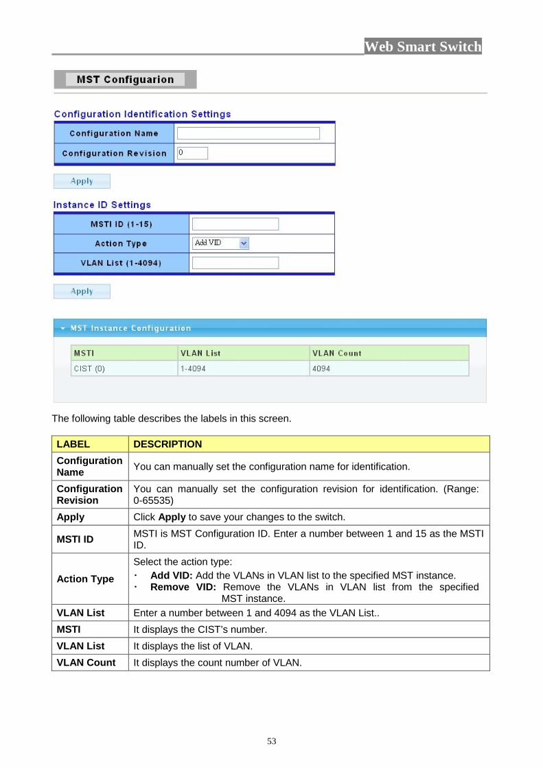
3.3.9.3 MST Configuration MST is the acronym of Minimum Spanning Tree. Click Switching > STP > MST Configuration.
Web Smart Switch
53
The following table describes the labels in this screen. LABEL DESCRIPTION Configuration Name You can manually set the configuration name for identification.
Configuration Revision
You can manually set the configuration revision for identification. (Range: 0-65535)
Apply Click Apply to save your changes to the switch.
MSTI ID MSTI is MST Configuration ID. Enter a number between 1 and 15 as the MSTI ID.
Action Type Select the action type: Add VID: Add the VLANs in VLAN list to the specified MST instance. Remove VID: Remove the VLANs in VLAN list from the specified
MST instance. VLAN List Enter a number between 1 and 4094 as the VLAN List.. MSTI It displays the CIST’s number. VLAN List It displays the list of VLAN. VLAN Count It displays the count number of VLAN.

Web Smart Switch
54
3.3.9.4 MST Instance Setting Click Switching > STP > MST Instance Setting.
The following table describes the labels in this screen. LABEL DESCRIPTION MST ID You can manually set the MST ID to specify MST instance. Priority You can manually set the Bridge Priority in the specified MST instance. Apply Click Apply to save your changes to the switch. MSTI It displays the CIST’s number. Instance Status It displays the status of MST instance.
Instance Priority It displays the priority of MST instance.
View Status Click View to view the status of MST instance.
3.3.9.5 MST Port Setting Click Switching > STP > MST Port Setting.
Web Smart Switch
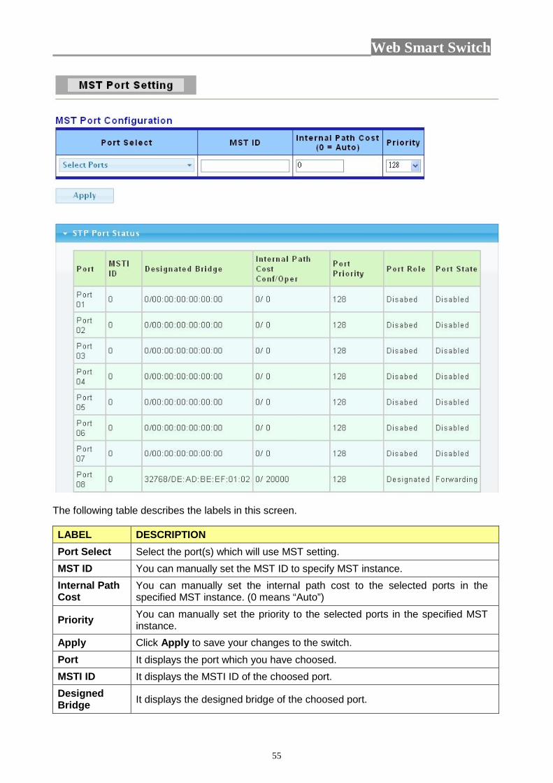
55
The following table describes the labels in this screen. LABEL DESCRIPTION Port Select Select the port(s) which will use MST setting. MST ID You can manually set the MST ID to specify MST instance. Internal Path Cost
You can manually set the internal path cost to the selected ports in the specified MST instance. (0 means “Auto”)
Priority You can manually set the priority to the selected ports in the specified MST instance.
Apply Click Apply to save your changes to the switch. Port It displays the port which you have choosed. MSTI ID It displays the MSTI ID of the choosed port. Designed Bridge It displays the designed bridge of the choosed port.
Web Smart Switch
56
Internal Path Cost It displays the internal path cost of the choosed port.
Port Priority It displays the port priority you have set. Port Role It displays the port role of the choosed port. Port State It displays the port state of the choosed port.
3.4 Security 3.4.1 Storm Control
The following table describes the labels in this screen.
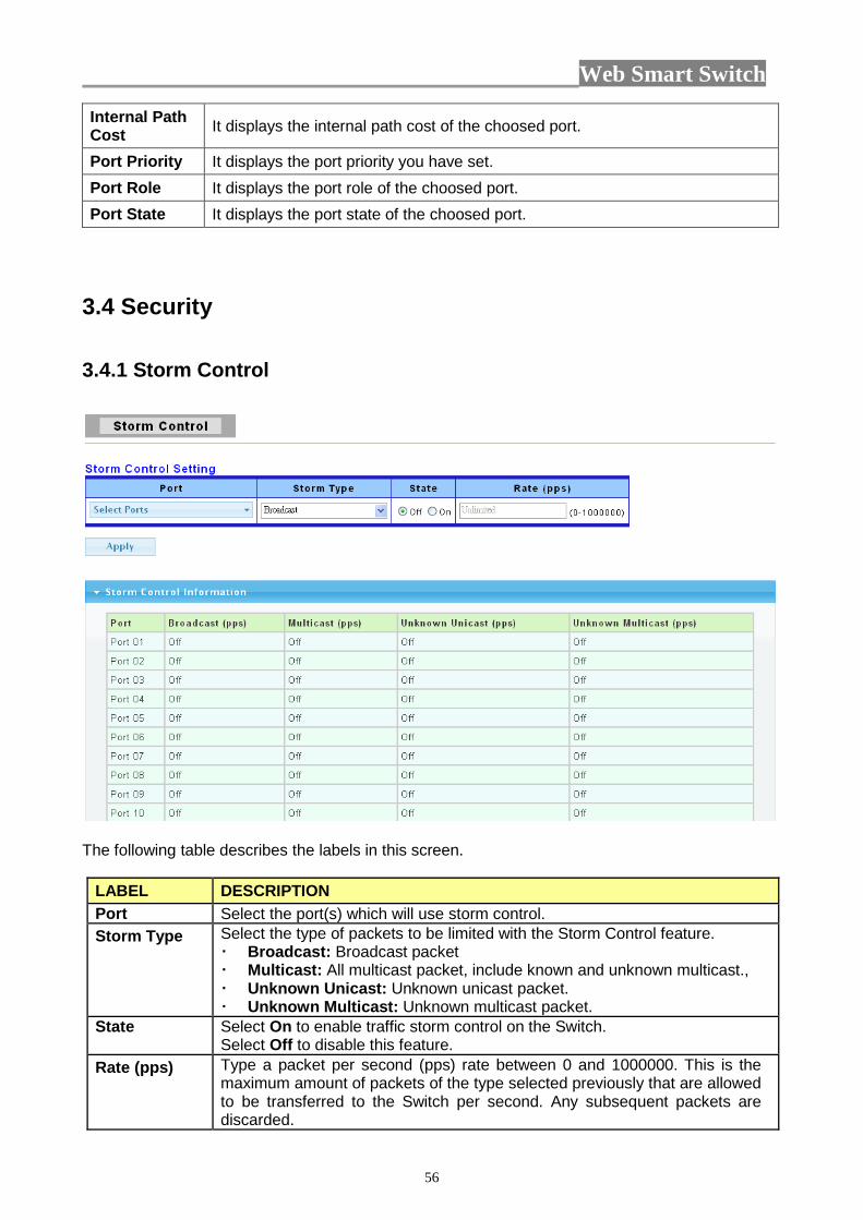
LABEL DESCRIPTION Port Select the port(s) which will use storm control. Storm Type Select the type of packets to be limited with the Storm Control feature.
Broadcast: Broadcast packet Multicast: All multicast packet, include known and unknown multicast., Unknown Unicast: Unknown unicast packet. Unknown Multicast: Unknown multicast packet.
State Select On to enable traffic storm control on the Switch. Select Off to disable this feature.
Rate (pps) Type a packet per second (pps) rate between 0 and 1000000. This is the maximum amount of packets of the type selected previously that are allowed to be transferred to the Switch per second. Any subsequent packets are discarded.

Web Smart Switch
57
Apply Click Apply to save your changes to the Switch.
Port This field displays the port number. Broadcast (pps)
This field displays how many broadcast packets can the port receive per second.
Multicast (pps)
This field displays how many multicast packets can the port receive per second.
Unknown Unicast (pps)
This field displays how many unknown unicast packets can the port receive per second.
Unknown Multicast (pps)
This field displays how many unknown multicast packets can the port receive per second.
3.4.2 MAC Filtering Use this screen to create rules for traffic going through the switch. Click Security> MAC Filtering in the navigation panel to display the screen as shown.
The following table describes the labels in this screen.
LABEL DESCRIPTION MAC Address Type a MAC address to which packets will be filtered in valid MAC
address format, that is, six hexadecimal character pairs. And this must be a unicast MAC address.
VLAN The VLAN ID number of the VLAN on which the above MAC address resides.. This function is set default in this switch.
Filter Select Source MAC to drop the frames with the source MAC address (specified in the MAC Address field). Select Destination MAC to drop the frames with the destination MAC address (specified in the MAC Address field). Select Both to drop frames with the source MAC address and destination MAC address which specified in the MAC Address field.
Web Smart Switch
58
Name Type a descriptive name (up to 32 printable ASCII characters) for this filtering rule. This is for identification only.
Add Click Add to add any port into the MAC filtering table.
No. This is the index number for the MAC filtering rules.
MAC Address This field displays the MAC address that will be filtered.
VLAN This is the VLAN group to which the MAC address belongs. Filter This field displays the action of the filter. Name This field displays the descriptive name for this rule. This is for
identification purpose only. Select Click on the checkbox for the MAC filtering rule you want to delete.
3.4.3 802.1X 3.4.3.1 802.1X Setting Use this screen to activate IEEE 802.1x security and configure RADIUS server settings. Click Security > 802.1x > 802.1x Setting to display the configuration screen as shown

Web Smart Switch
59
The following table describes the labels in this screen.
LABEL DESCRIPTION 802.1X Select Enable from the drop-down list box to activate IEEE 802.1x port
authentication. Select Disable to disable this function.
Radius Server IP Enter the IP address of an external RADIUS server in dotted decimal notation.
Server Port (1024-65535)
The default port of a RADIUS server for authentication is 1812. You need not change this value unless your network administrator instructs you to do so.
Shared Key (max. 30 characters)
Specify a password (up to 32 alphanumeric characters) as the key to be shared between the external RADIUS server and the Switch. This key is not sent over the network. This key must be the same on the external RADIUS server and the Switch.
Retype Shared Key
Retype the key specified above to ensure it has been entered correctly.
Reauthentication enable
Specify if a subscriber has to periodically re-enter his or her username and password to stay connected to the port. Select Enable means the user has to re-enter his/her username and
Web Smart Switch
60
password. Reauthentication Period (30-65535 sec)
Specify how often a client has to re-enter his or her username and password to stay connected to the port. Set the reauthentication period of 802.1X if reauthentication is enabled.
Apply Click Apply to save your changes to the switch.
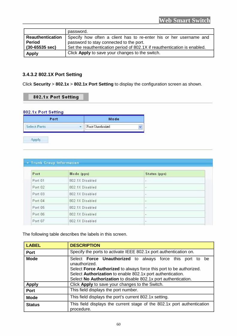
3.4.3.2 802.1X Port Setting Click Security > 802.1x > 802.1x Port Setting to display the configuration screen as shown.
The following table describes the labels in this screen.
LABEL DESCRIPTION Port Specify the ports to activate IEEE 802.1x port authentication on. Mode Select Force Unauthorized to always force this port to be
unauthorized. Select Force Authorized to always force this port to be authorized. Select Authorization to enable 802.1x port authentication. Select No Authorization to disable 802.1x port authentication.
Apply Click Apply to save your changes to the Switch. Port This field displays the port number.
Mode This field displays the port’s current 802.1x setting.
Status This field displays the current stage of the 802.1x port authentication procedure.
Web Smart Switch
61
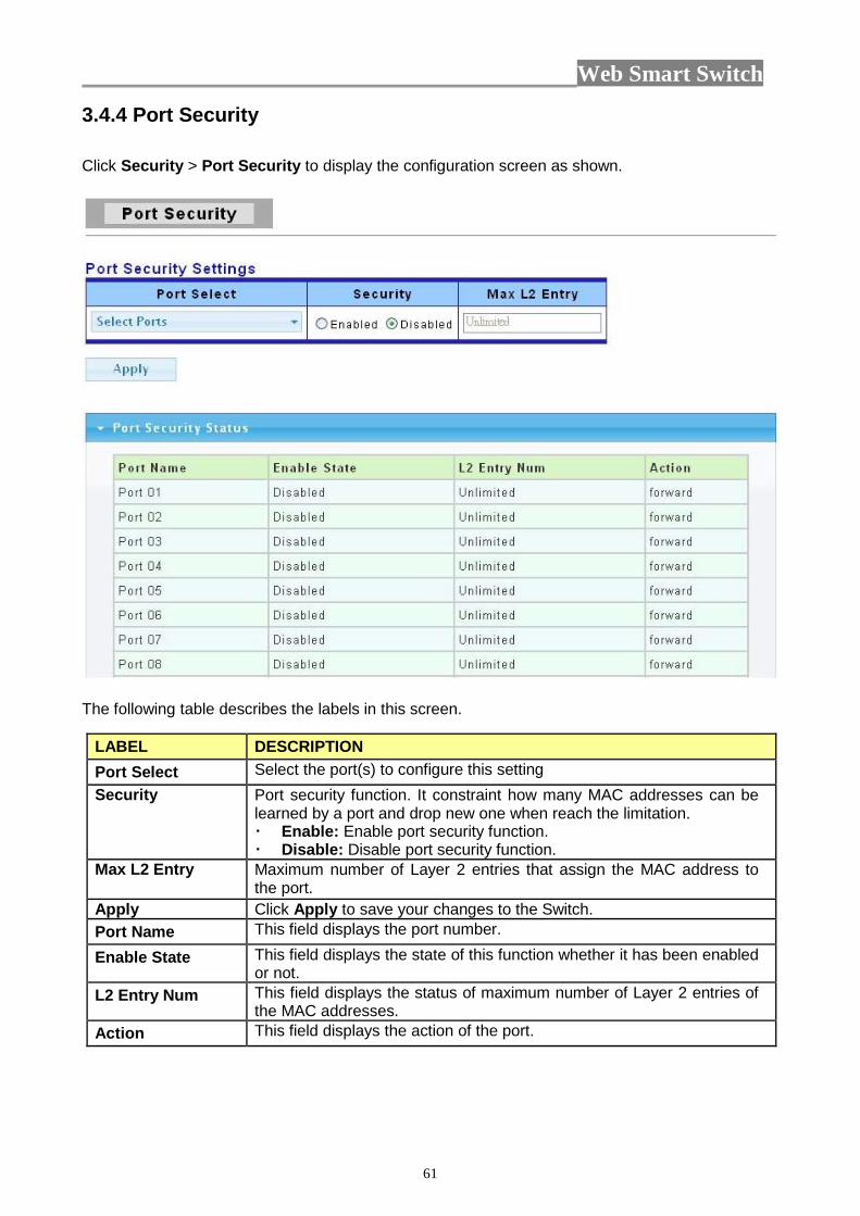
3.4.4 Port Security Click Security > Port Security to display the configuration screen as shown.
The following table describes the labels in this screen.
LABEL DESCRIPTION Port Select Select the port(s) to configure this setting Security Port security function. It constraint how many MAC addresses can be
learned by a port and drop new one when reach the limitation. Enable: Enable port security function. Disable: Disable port security function.
Max L2 Entry Maximum number of Layer 2 entries that assign the MAC address to the port.
Apply Click Apply to save your changes to the Switch. Port Name This field displays the port number.
Enable State This field displays the state of this function whether it has been enabled or not.
L2 Entry Num This field displays the status of maximum number of Layer 2 entries of the MAC addresses.
Action This field displays the action of the port.

Web Smart Switch
62
3.4.5 Protected Ports This page allow user to configure protected port setting to prevent the selected ports from communicate with each other. Click Security > Protected Ports to display the configuration screen as shown.
The following table describes the labels in this screen.
LABEL DESCRIPTION Port List To select the port to be protected. Port Type Configure port protect type:
Unprotected: Unprotected port can communicate with all ports. Protected: Prevent protected ports from communicate with each
other. Apply Click Apply to save your changes to the Switch.
3.4.6 Access 3.4.6.1 Console

Web Smart Switch
63
The following table describes the labels in this screen.
LABEL DESCRIPTION Session Timeout Set session timeout minutes for user access CLI from console line. If
user doesn’t response after session timeout minute, CLI will logout automatically. Enter a number between 0 and 1440 as the session timeout. 0 minutes means never timeout.
Apply Click Apply to save your changes to the Switch. 3.4.6.2 Telnet Telnet is the TCP/IP standard protocol for remote terminal service. TELNET allows a user at one site to interact with a remote timesharing system at another site as if the user’s keyboard and display connected directly to the remote machine.

Web Smart Switch
64
The following table describes the labels in this screen.
LABEL DESCRIPTION Session Timeout Set session timeout minutes for user access CLI from telnet line. If user
doesn’t response after session timeout minute, CLI will logout automatically. Enter a number between 0 and 1440 as the session timeout. 0 minutes means never timeout.
Apply Click Apply to save your changes to the Switch. 3.4.6.3 SSH SSH is the acronym of Secure Shell.

Web Smart Switch
65
The following table describes the labels in this screen.
LABEL DESCRIPTION Session Timeout Set session timeout minutes for user access CLI from SSH line. If user
doesn’t response after session timeout minute, CLI will logout automatically. Enter a number between 0 and 1440 as the session timeout. 0 minutes means never timeout.
Apply Click Apply to save your changes to the Switch. 3.4.6.4 HTTP HTTP is the acronym of Hyper Text Transfer Protocol.
The following table describes the labels in this screen.
LABEL DESCRIPTION Session Timeout Set session timeout minutes for user access WEB from HTTP protocol.
If user doesn’t response after session timeout minute, WEB UI will logout automatically. Enter a number between 0 and 1440 as the session timeout. 0 minutes means never timeout.
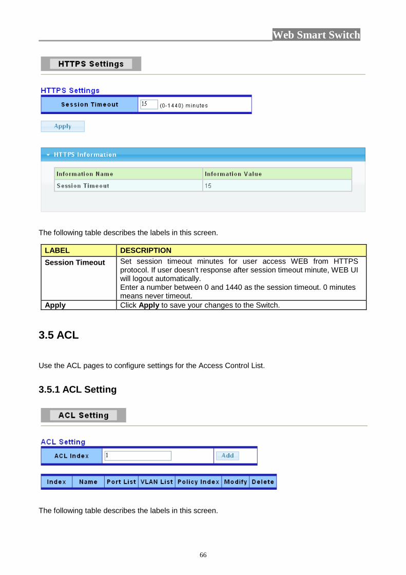
Apply Click Apply to save your changes to the Switch. 3.4.6.5 HTTPS HTTPS is the acronym of Hypertext Transfer Protocol over Secure Socket Layer.
Web Smart Switch
66
The following table describes the labels in this screen.
LABEL DESCRIPTION Session Timeout Set session timeout minutes for user access WEB from HTTPS
protocol. If user doesn’t response after session timeout minute, WEB UI will logout automatically. Enter a number between 0 and 1440 as the session timeout. 0 minutes means never timeout.
Apply Click Apply to save your changes to the Switch.
3.5 ACL Use the ACL pages to configure settings for the Access Control List. 3.5.1 ACL Setting
The following table describes the labels in this screen.
Web Smart Switch
67
LABEL DESCRIPTION ACL Index You can manually set the ACL Index. Add Click Add to add the basic information of ACL Index. Index It displays the index information. Name It displays the name of the index. Port List It displays the list of the port. VLAN List It displays the list of the VLAN. Policy Index It displays the policy index. Modify Click Modify to modify any setting. Delete Click Delete to delete any setting.
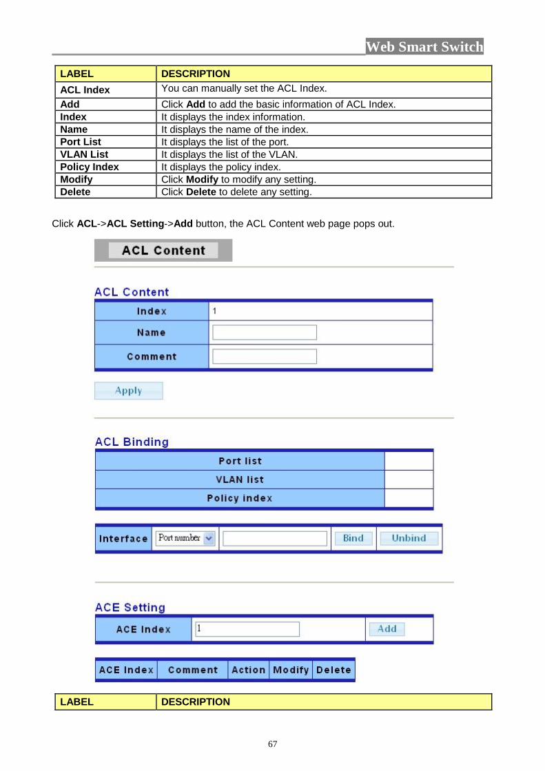
Click ACL->ACL Setting->Add button, the ACL Content web page pops out.
LABEL DESCRIPTION
Web Smart Switch
68
Name Enter ACL name in this field Comment Enter ACL comment in this field. Interface Select the interface to bind:
Port number: Enter port number. VLAN ID: Enter VLAN ID. Policy: Enter policy index.
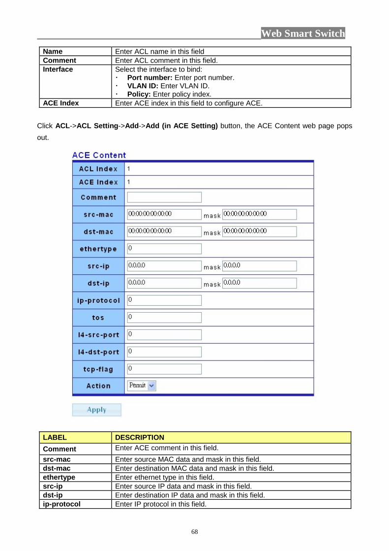
ACE Index Enter ACE index in this field to configure ACE. Click ACL->ACL Setting->Add->Add (in ACE Setting) button, the ACE Content web page pops out.
LABEL DESCRIPTION Comment Enter ACE comment in this field. src-mac Enter source MAC data and mask in this field. dst-mac Enter destination MAC data and mask in this field. ethertype Enter ethernet type in this field. src-ip Enter source IP data and mask in this field. dst-ip Enter destination IP data and mask in this field. ip-protocol Enter IP protocol in this field.

Web Smart Switch
69
tos Enter ToS in this field. 14-src-port Enter Layer 4 source port in this field. 14-dst-port Enter Layer 4 destination port in this field. tcp-flag Enter TCP flag in this field. Action Select the action to take:
Permit: permit packet to pass through. Deny: drop packet. Note: system will automatically add one “deny any any” rule in the last rule of this ACL.
3.5.2 ACL Template Setting
The following table describes the labels in this screen.
LABEL DESCRIPTION Template Index You can choose the template index. Get To get the basic information of the policy index. src-mac Click in the square box to set source MAC into Template. dst-mac Click in the square box to set destination MAC into Template. ethertype Click in the square box to set ethernet type into Template. src-ip Click in the square box to set source IP into Template. dst-ip Click in the square box to set destination IP into Template. ip-protocol Click in the square box to set IP protocol into Template. tos Click in the square box to set ToS into Template.
Web Smart Switch
70
14-src-port Click in the square box to set Layer 4 source port into Template. 14-dst-port Click in the square box to set Layer 4 destination port into Template. tcp-flag Click in the square box to set TCP flag into Template. Apply Click Apply to save your changes to the switch.
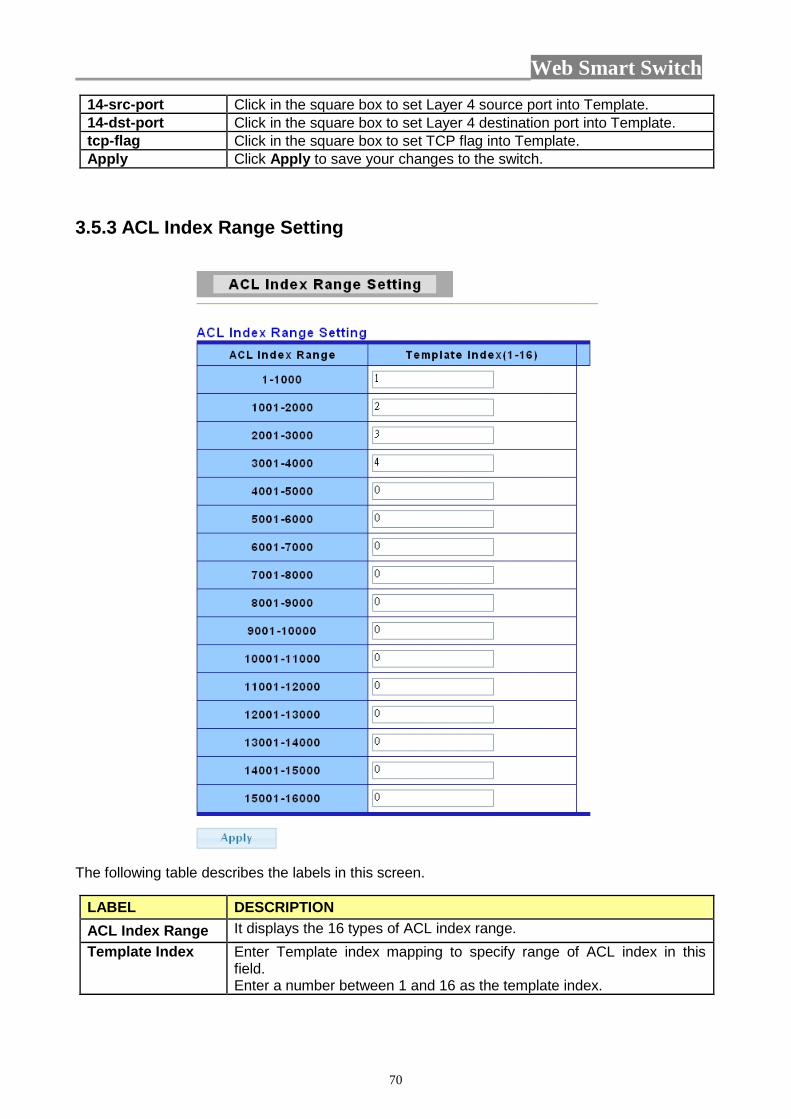
3.5.3 ACL Index Range Setting
The following table describes the labels in this screen.
LABEL DESCRIPTION ACL Index Range It displays the 16 types of ACL index range. Template Index Enter Template index mapping to specify range of ACL index in this
field. Enter a number between 1 and 16 as the template index.
Web Smart Switch
71
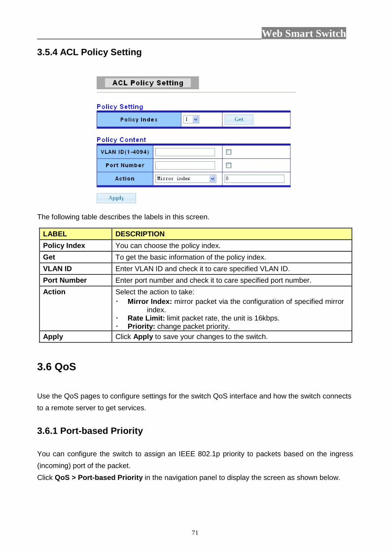
3.5.4 ACL Policy Setting
The following table describes the labels in this screen.
LABEL DESCRIPTION Policy Index You can choose the policy index. Get To get the basic information of the policy index. VLAN ID Enter VLAN ID and check it to care specified VLAN ID. Port Number Enter port number and check it to care specified port number. Action Select the action to take:
Mirror Index: mirror packet via the configuration of specified mirror index.
Rate Limit: limit packet rate, the unit is 16kbps. Priority: change packet priority.
Apply Click Apply to save your changes to the switch.
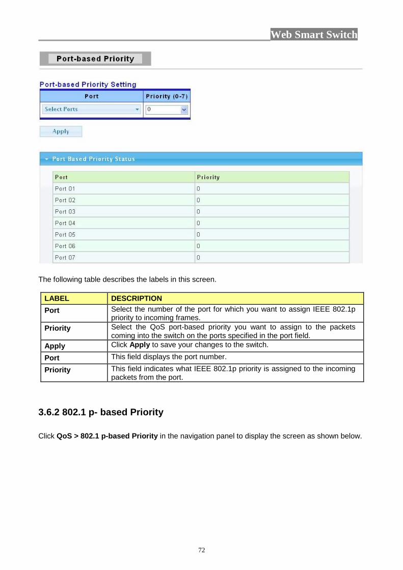
3.6 QoS Use the QoS pages to configure settings for the switch QoS interface and how the switch connects to a remote server to get services. 3.6.1 Port-based Priority You can configure the switch to assign an IEEE 802.1p priority to packets based on the ingress (incoming) port of the packet. Click QoS > Port-based Priority in the navigation panel to display the screen as shown below.
Web Smart Switch
72
The following table describes the labels in this screen.
LABEL DESCRIPTION Port Select the number of the port for which you want to assign IEEE 802.1p
priority to incoming frames. Priority Select the QoS port-based priority you want to assign to the packets
coming into the switch on the ports specified in the port field. Apply Click Apply to save your changes to the switch.
Port This field displays the port number.
Priority This field indicates what IEEE 802.1p priority is assigned to the incoming packets from the port.
3.6.2 802.1 p- based Priority Click QoS > 802.1 p-based Priority in the navigation panel to display the screen as shown below.

Web Smart Switch
73
The following table describes the labels in this screen.
LABEL DESCRIPTION 802.1 p Select the 802.1p value to mapping to the priority and drop precedence.
The 802.1p range is 0 to 7. Priority Select the IEEE 802.1p priority you want to assign to the packets coming
into the switch on the ports specified in the port field. The priority range is 0 to 7.
Apply Click Apply to save your changes to the switch.
802.1 p This field displays the 802.1p priority level which you’ve choosed..
Priority This field indicates what IEEE 802.1p priority is assigned to the incoming packets from the port.
3.6.3 DSCP - based Priority You can configure the switch to assign an IEEE 802.1p priority to packets coming into the switch with DSCPs assigned to them. Click QoS > DSCP-based Priority to display the screen as shown next.

Web Smart Switch
74
The following table describes the labels in this screen.
LABEL DESCRIPTION DSCP Select the DSCP value to mapping to the priority and drop precedence.
The DSCP range is 0 to 63. Priority Select the priority value that the DSCP mapped to. The priority range is
0 to 7. Apply Click Apply to save your changes to the switch.
DSCP This field displays the DSCP classification identification numbers.
Priority This field displays the DSCP classification identification number’s IEEE 802.1p Priority.
3.6.4 Priority to Queue Mapping Click QoS > Priority to Queue Mapping to display the screen as shown next. IEEE 802.1p defines up to eight separate traffic types by inserting a tag into a MAC-layer frame that contains bits to define class of service. Frames without an explicit priority tag are given the default priority of the ingress port. Use the next screen to configure the priority level-to-physical queue mapping. The Switch has eight physical queues that you can map to the 8 priority levels. On the Switch,
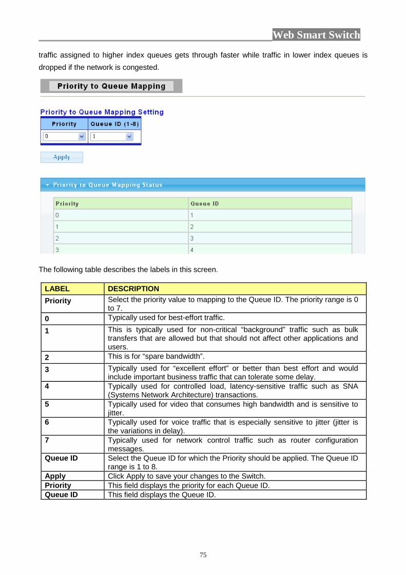
Web Smart Switch
75
traffic assigned to higher index queues gets through faster while traffic in lower index queues is dropped if the network is congested.
The following table describes the labels in this screen.
LABEL DESCRIPTION Priority Select the priority value to mapping to the Queue ID. The priority range is 0
to 7. 0 Typically used for best-effort traffic.
1 This is typically used for non-critical “background” traffic such as bulk transfers that are allowed but that should not affect other applications and users.
2 This is for “spare bandwidth”.
3 Typically used for “excellent effort” or better than best effort and would include important business traffic that can tolerate some delay.
4 Typically used for controlled load, latency-sensitive traffic such as SNA (Systems Network Architecture) transactions.
5 Typically used for video that consumes high bandwidth and is sensitive to jitter.
6 Typically used for voice traffic that is especially sensitive to jitter (jitter is the variations in delay).
7 Typically used for network control traffic such as router configuration messages.
Queue ID Select the Queue ID for which the Priority should be applied. The Queue ID range is 1 to 8.
Apply Click Apply to save your changes to the Switch. Priority This field displays the priority for each Queue ID. Queue ID This field displays the Queue ID.
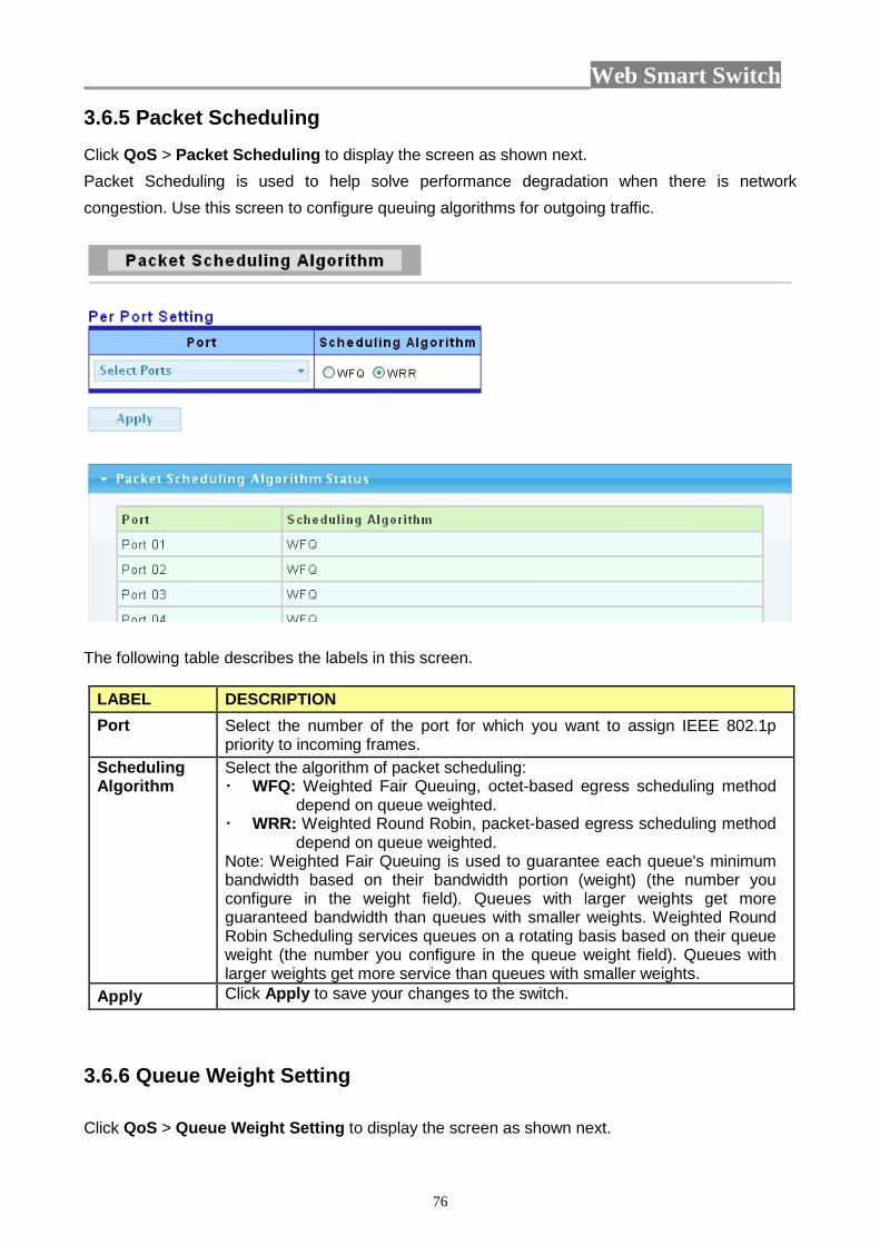
Web Smart Switch
76
3.6.5 Packet Scheduling Click QoS > Packet Scheduling to display the screen as shown next. Packet Scheduling is used to help solve performance degradation when there is network congestion. Use this screen to configure queuing algorithms for outgoing traffic.
The following table describes the labels in this screen.
LABEL DESCRIPTION Port Select the number of the port for which you want to assign IEEE 802.1p
priority to incoming frames. Scheduling Algorithm
Select the algorithm of packet scheduling: WFQ: Weighted Fair Queuing, octet-based egress scheduling method
depend on queue weighted. WRR: Weighted Round Robin, packet-based egress scheduling method
depend on queue weighted. Note: Weighted Fair Queuing is used to guarantee each queue's minimum bandwidth based on their bandwidth portion (weight) (the number you configure in the weight field). Queues with larger weights get more guaranteed bandwidth than queues with smaller weights. Weighted Round Robin Scheduling services queues on a rotating basis based on their queue weight (the number you configure in the queue weight field). Queues with larger weights get more service than queues with smaller weights.
Apply Click Apply to save your changes to the switch.
3.6.6 Queue Weight Setting Click QoS > Queue Weight Setting to display the screen as shown next.
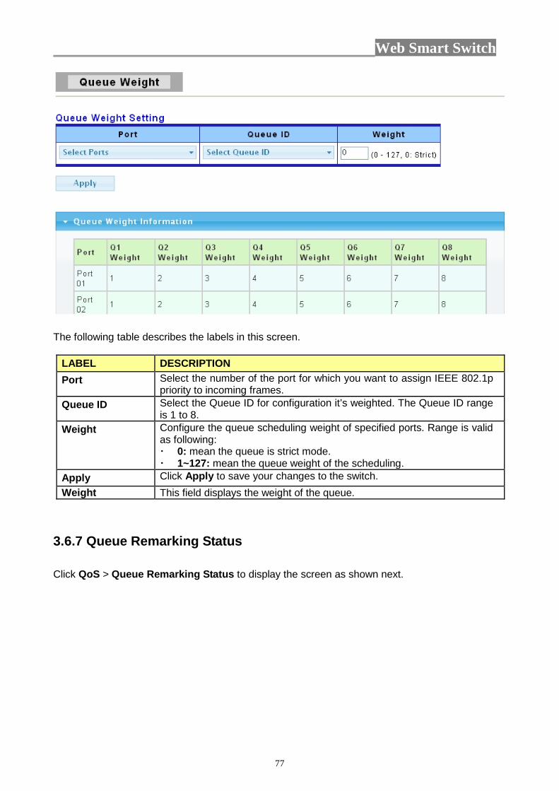
Web Smart Switch
77
The following table describes the labels in this screen.
LABEL DESCRIPTION Port Select the number of the port for which you want to assign IEEE 802.1p
priority to incoming frames. Queue ID Select the Queue ID for configuration it’s weighted. The Queue ID range
is 1 to 8. Weight Configure the queue scheduling weight of specified ports. Range is valid
as following: 0: mean the queue is strict mode. 1~127: mean the queue weight of the scheduling.
Apply Click Apply to save your changes to the switch. Weight This field displays the weight of the queue.
3.6.7 Queue Remarking Status Click QoS > Queue Remarking Status to display the screen as shown next.
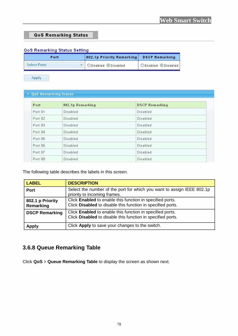
Web Smart Switch
78
The following table describes the labels in this screen.
LABEL DESCRIPTION Port Select the number of the port for which you want to assign IEEE 802.1p
priority to incoming frames. 802.1 p Priority Remarking
Click Enabled to enable this function in specified ports. Click Disabled to disable this function in specified ports.
DSCP Remarking Click Enabled to enable this function in specified ports. Click Disabled to disable this function in specified ports.
Apply Click Apply to save your changes to the switch.
3.6.8 Queue Remarking Table Click QoS > Queue Remarking Table to display the screen as shown next.
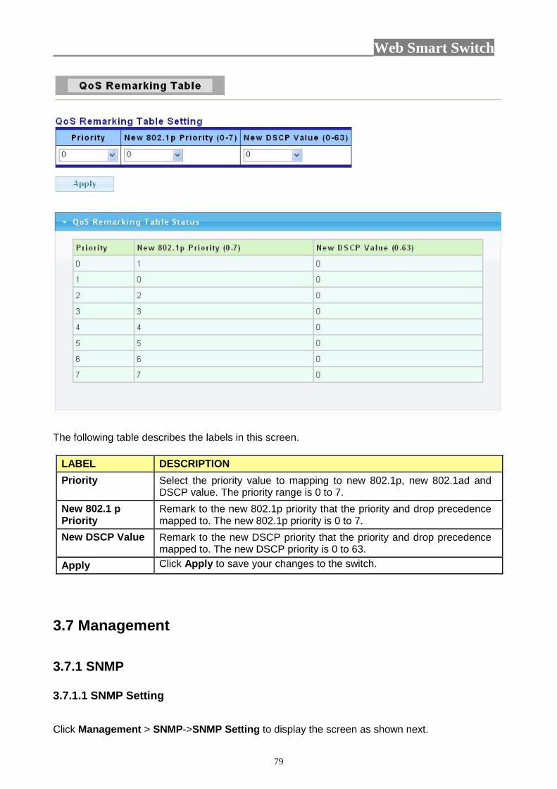
Web Smart Switch
79
The following table describes the labels in this screen.
LABEL DESCRIPTION Priority Select the priority value to mapping to new 802.1p, new 802.1ad and
DSCP value. The priority range is 0 to 7. New 802.1 p Priority
Remark to the new 802.1p priority that the priority and drop precedence mapped to. The new 802.1p priority is 0 to 7.
New DSCP Value Remark to the new DSCP priority that the priority and drop precedence mapped to. The new DSCP priority is 0 to 63.
Apply Click Apply to save your changes to the switch.
3.7 Management 3.7.1 SNMP 3.7.1.1 SNMP Setting
Click Management > SNMP->SNMP Setting to display the screen as shown next.

Web Smart Switch
80
The following table describes the labels in this screen.
LABEL DESCRIPTION State SNMP daemon state:
Select Enabled to activate SNMP daemon. Select Disabled to not use SNMP daemon.
3.7.1.2 SNMP Community Click Management > SNMP->SNMP Community to display the screen as shown next.
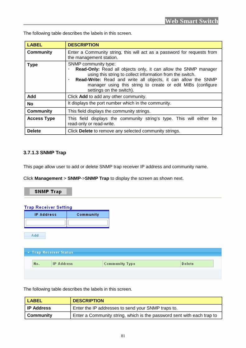
Web Smart Switch
81
The following table describes the labels in this screen.
LABEL DESCRIPTION Community Enter a Community string, this will act as a password for requests from
the management station. Type SNMP community type:
Read-Only: Read all objects only, it can allow the SNMP manager using this string to collect information from the switch.
Read-Write: Read and write all objects, it can allow the SNMP manager using this string to create or edit MIBs (configure settings on the switch).
Add Click Add to add any other community. No It displays the port number which in the community.
Community This field displays the community strings. Access Type This field displays the community string’s type. This will either be
read-only or read-write. Delete Click Delete to remove any selected community strings.
3.7.1.3 SNMP Trap This page allow user to add or delete SNMP trap receiver IP address and community name. Click Management > SNMP->SNMP Trap to display the screen as shown next.
The following table describes the labels in this screen.
LABEL DESCRIPTION IP Address Enter the IP addresses to send your SNMP traps to. Community Enter a Community string, which is the password sent with each trap to
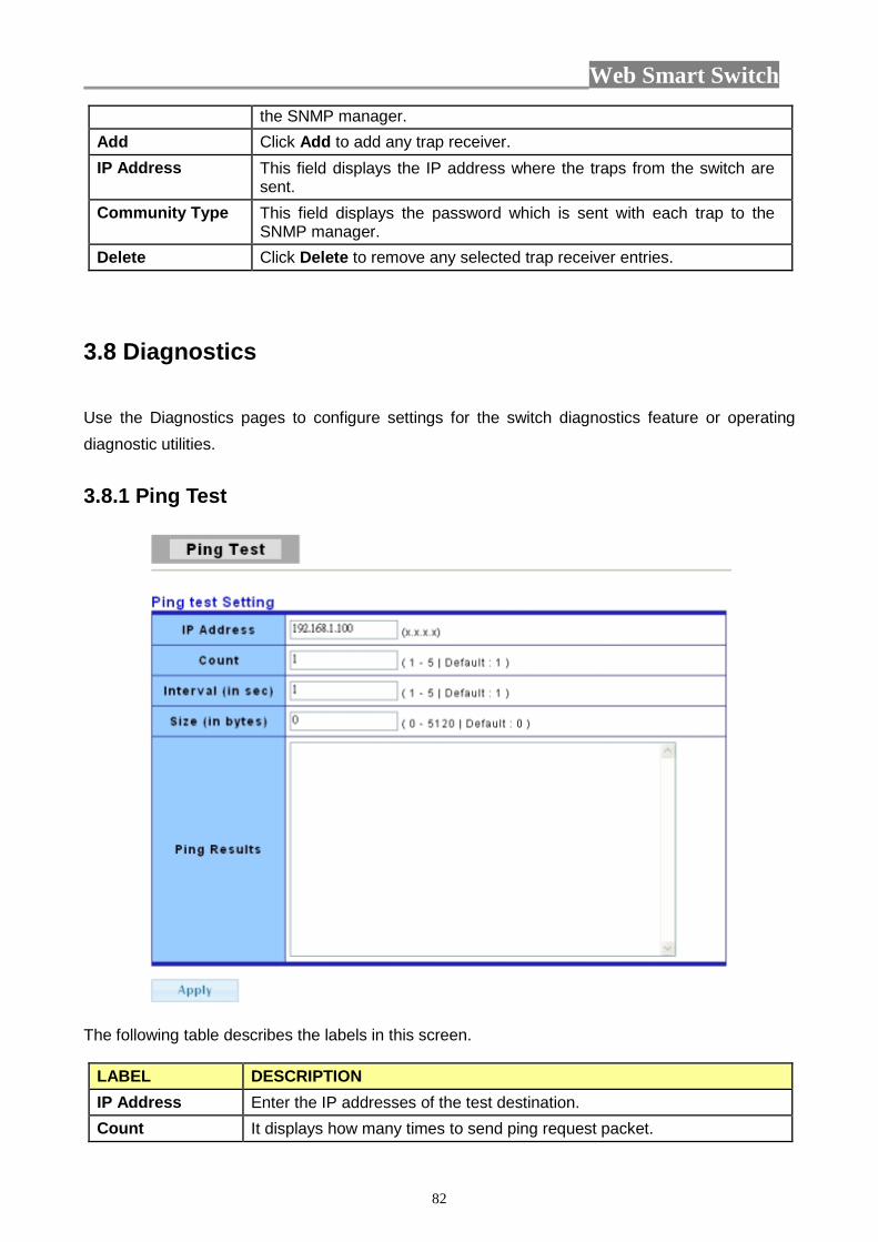
Web Smart Switch
82
the SNMP manager. Add Click Add to add any trap receiver. IP Address This field displays the IP address where the traps from the switch are
sent. Community Type This field displays the password which is sent with each trap to the
SNMP manager. Delete Click Delete to remove any selected trap receiver entries.
3.8 Diagnostics Use the Diagnostics pages to configure settings for the switch diagnostics feature or operating diagnostic utilities.
3.8.1 Ping Test
The following table describes the labels in this screen.
LABEL DESCRIPTION IP Address Enter the IP addresses of the test destination. Count It displays how many times to send ping request packet.
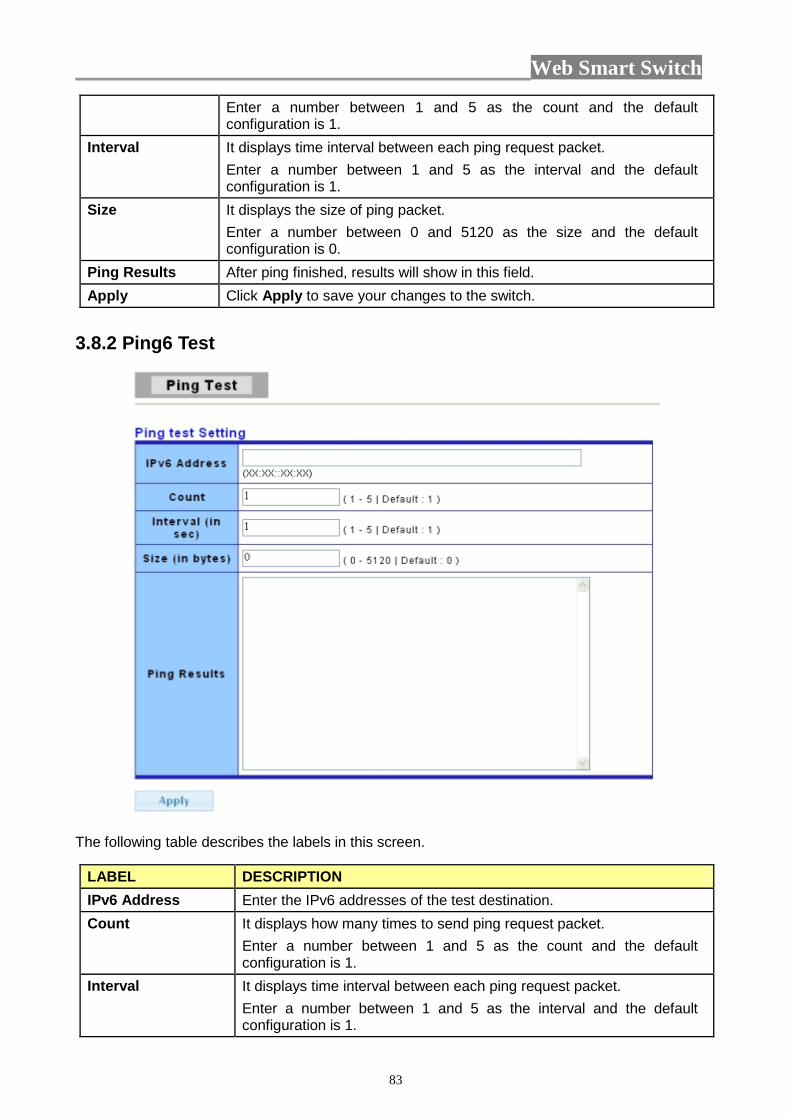
Web Smart Switch
83
Enter a number between 1 and 5 as the count and the default configuration is 1.
Interval It displays time interval between each ping request packet. Enter a number between 1 and 5 as the interval and the default configuration is 1.
Size It displays the size of ping packet. Enter a number between 0 and 5120 as the size and the default configuration is 0.
Ping Results After ping finished, results will show in this field. Apply Click Apply to save your changes to the switch.
3.8.2 Ping6 Test
The following table describes the labels in this screen.
LABEL DESCRIPTION IPv6 Address Enter the IPv6 addresses of the test destination. Count It displays how many times to send ping request packet.
Enter a number between 1 and 5 as the count and the default configuration is 1.
Interval It displays time interval between each ping request packet. Enter a number between 1 and 5 as the interval and the default configuration is 1.
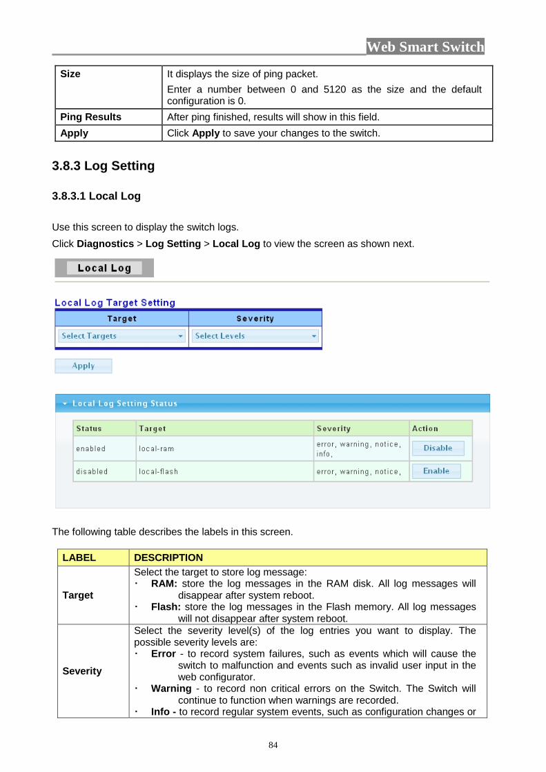
Web Smart Switch
84
Size It displays the size of ping packet. Enter a number between 0 and 5120 as the size and the default configuration is 0.
Ping Results After ping finished, results will show in this field. Apply Click Apply to save your changes to the switch.
3.8.3 Log Setting 3.8.3.1 Local Log Use this screen to display the switch logs. Click Diagnostics > Log Setting > Local Log to view the screen as shown next.
The following table describes the labels in this screen.
LABEL DESCRIPTION
Target
Select the target to store log message: RAM: store the log messages in the RAM disk. All log messages will
disappear after system reboot. Flash: store the log messages in the Flash memory. All log messages
will not disappear after system reboot.
Severity
Select the severity level(s) of the log entries you want to display. The possible severity levels are: Error - to record system failures, such as events which will cause the
switch to malfunction and events such as invalid user input in the web configurator.
Warning - to record non critical errors on the Switch. The Switch will continue to function when warnings are recorded.
Info - to record regular system events, such as configuration changes or
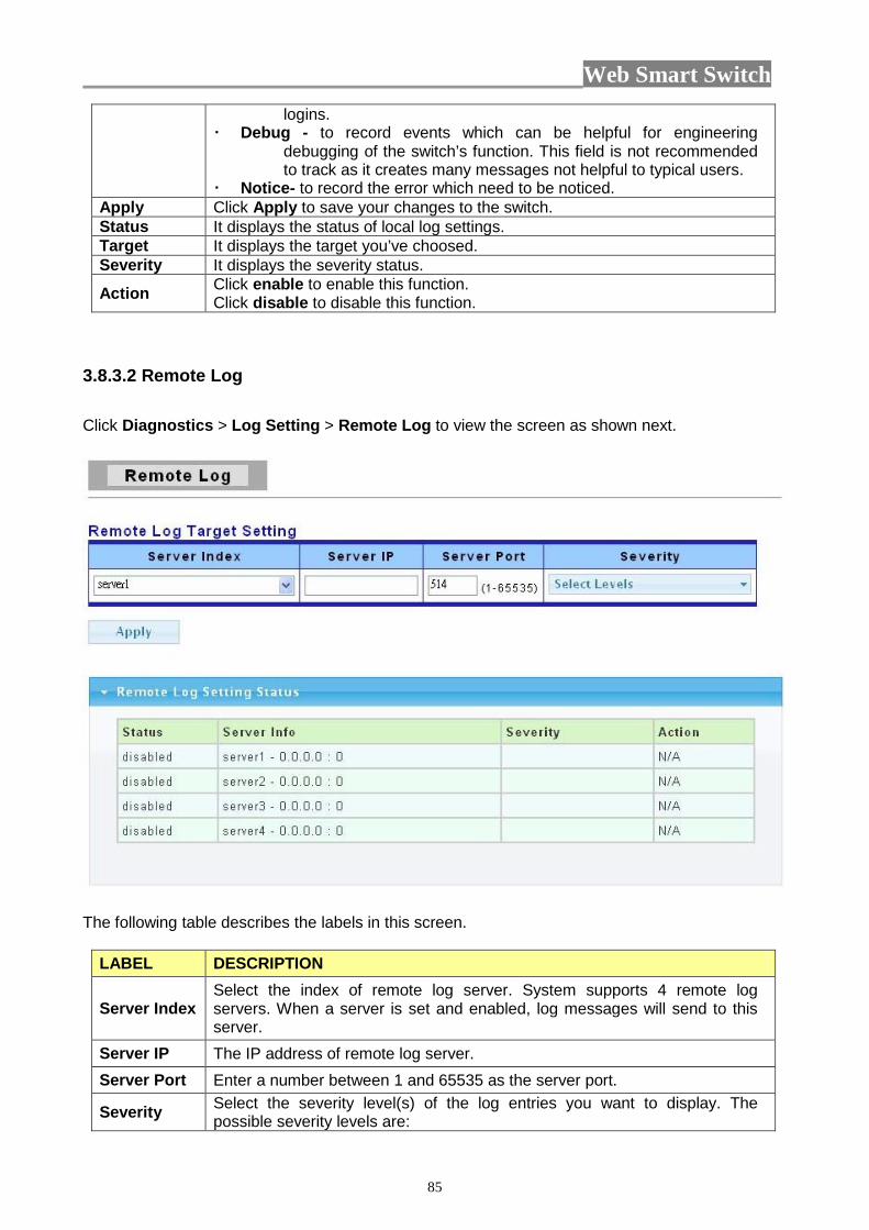
Web Smart Switch
85
logins. Debug - to record events which can be helpful for engineering
debugging of the switch’s function. This field is not recommended to track as it creates many messages not helpful to typical users.
Notice- to record the error which need to be noticed. Apply Click Apply to save your changes to the switch. Status It displays the status of local log settings. Target It displays the target you’ve choosed. Severity It displays the severity status.
Action Click enable to enable this function. Click disable to disable this function.
3.8.3.2 Remote Log Click Diagnostics > Log Setting > Remote Log to view the screen as shown next.
The following table describes the labels in this screen.
LABEL DESCRIPTION
Server Index Select the index of remote log server. System supports 4 remote log servers. When a server is set and enabled, log messages will send to this server.
Server IP The IP address of remote log server. Server Port Enter a number between 1 and 65535 as the server port.
Severity Select the severity level(s) of the log entries you want to display. The possible severity levels are:
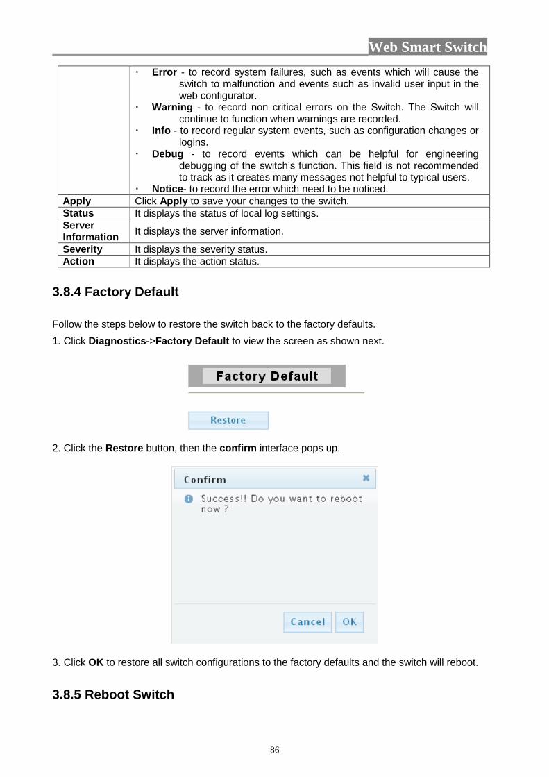
Web Smart Switch
86
Error - to record system failures, such as events which will cause the switch to malfunction and events such as invalid user input in the web configurator.
Warning - to record non critical errors on the Switch. The Switch will continue to function when warnings are recorded.
Info - to record regular system events, such as configuration changes or logins.
Debug - to record events which can be helpful for engineering debugging of the switch’s function. This field is not recommended to track as it creates many messages not helpful to typical users.
Notice- to record the error which need to be noticed. Apply Click Apply to save your changes to the switch. Status It displays the status of local log settings. Server Information It displays the server information.
Severity It displays the severity status. Action It displays the action status.
3.8.4 Factory Default Follow the steps below to restore the switch back to the factory defaults. 1. Click Diagnostics->Factory Default to view the screen as shown next.
2. Click the Restore button, then the confirm interface pops up.
3. Click OK to restore all switch configurations to the factory defaults and the switch will reboot. 3.8.5 Reboot Switch
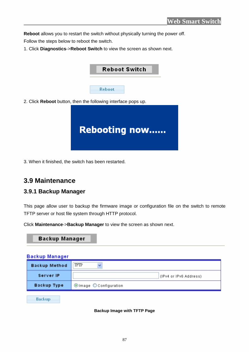
Web Smart Switch
87
Reboot allows you to restart the switch without physically turning the power off. Follow the steps below to reboot the switch. 1. Click Diagnostics->Reboot Switch to view the screen as shown next.
2. Click Reboot button, then the following interface pops up.
3. When it finished, the switch has been restarted.
3.9 Maintenance 3.9.1 Backup Manager This page allow user to backup the firmware image or configuration file on the switch to remote TFTP server or host file system through HTTP protocol. Click Maintenance->Backup Manager to view the screen as shown next.
Backup Image with TFTP Page

Web Smart Switch
88
Backup Config with TFTP Page
Backup Image with HTTP Page
Backup Config with HTTP Page
The following table describes the labels in this screen.
LABEL DESCRIPTION
Backup Select backup method:
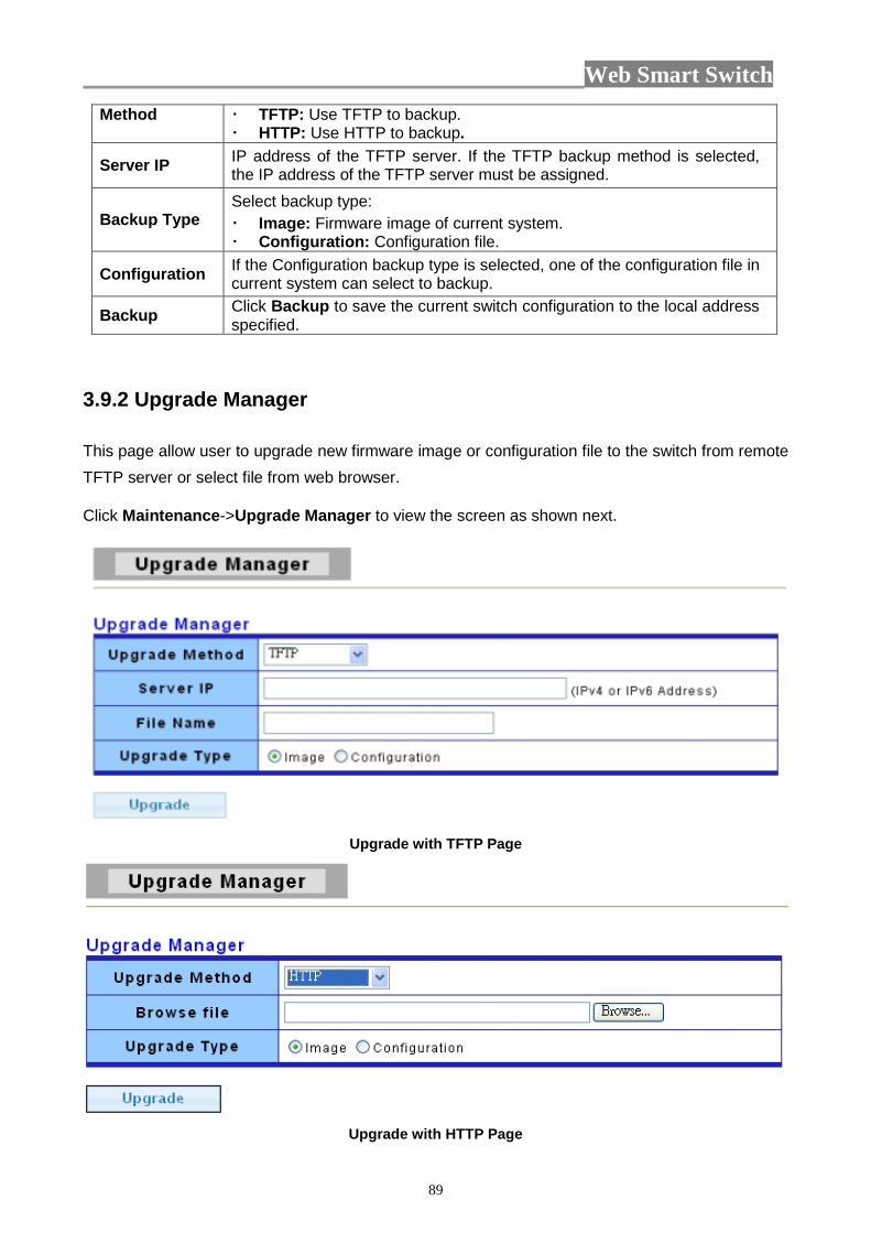
Web Smart Switch
89
Method TFTP: Use TFTP to backup. HTTP: Use HTTP to backup.
Server IP IP address of the TFTP server. If the TFTP backup method is selected, the IP address of the TFTP server must be assigned.
Backup Type Select backup type: Image: Firmware image of current system. Configuration: Configuration file.
Configuration If the Configuration backup type is selected, one of the configuration file in current system can select to backup.
Backup Click Backup to save the current switch configuration to the local address specified.
3.9.2 Upgrade Manager This page allow user to upgrade new firmware image or configuration file to the switch from remote TFTP server or select file from web browser. Click Maintenance->Upgrade Manager to view the screen as shown next.
Upgrade with TFTP Page
Upgrade with HTTP Page
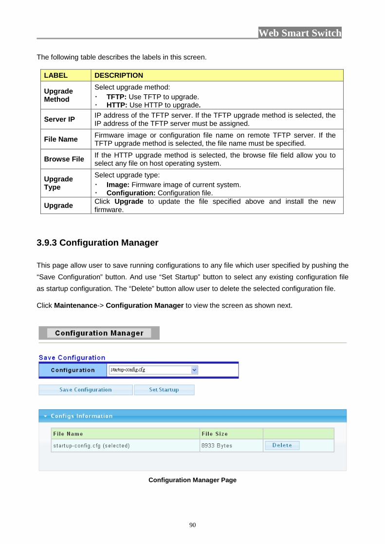
Web Smart Switch
90
The following table describes the labels in this screen.
LABEL DESCRIPTION
Upgrade Method
Select upgrade method: TFTP: Use TFTP to upgrade. HTTP: Use HTTP to upgrade.
Server IP IP address of the TFTP server. If the TFTP upgrade method is selected, the IP address of the TFTP server must be assigned.
File Name Firmware image or configuration file name on remote TFTP server. If the TFTP upgrade method is selected, the file name must be specified.
Browse File If the HTTP upgrade method is selected, the browse file field allow you to select any file on host operating system.
Upgrade Type
Select upgrade type: Image: Firmware image of current system. Configuration: Configuration file.
Upgrade Click Upgrade to update the file specified above and install the new firmware.
3.9.3 Configuration Manager This page allow user to save running configurations to any file which user specified by pushing the “Save Configuration” button. And use “Set Startup” button to select any existing configuration file as startup configuration. The “Delete” button allow user to delete the selected configuration file. Click Maintenance-> Configuration Manager to view the screen as shown next.
Configuration Manager Page
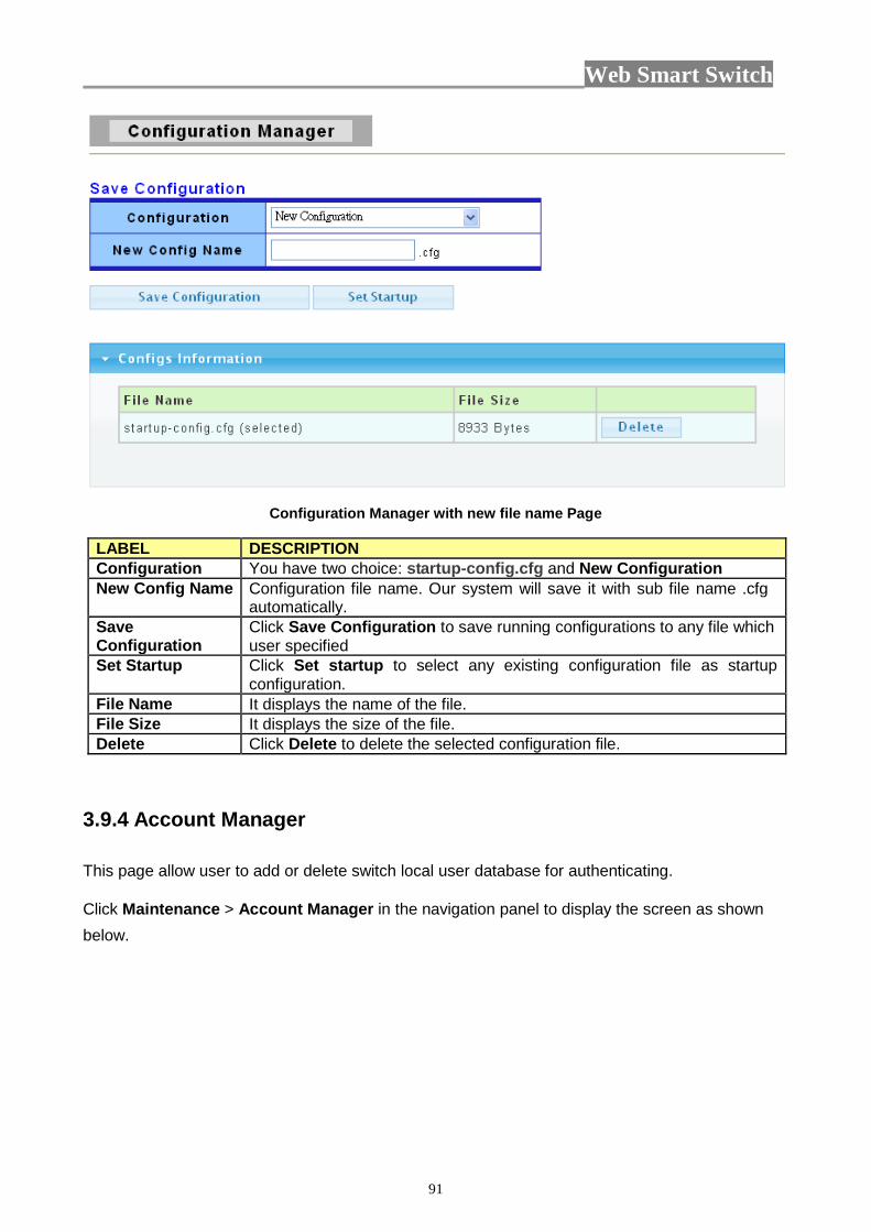
Web Smart Switch
91
Configuration Manager with new file name Page
LABEL DESCRIPTION Configuration You have two choice: startup-config.cfg and New Configuration New Config Name Configuration file name. Our system will save it with sub file name .cfg
automatically. Save Configuration
Click Save Configuration to save running configurations to any file which user specified
Set Startup Click Set startup to select any existing configuration file as startup configuration.
File Name It displays the name of the file. File Size It displays the size of the file. Delete Click Delete to delete the selected configuration file.
3.9.4 Account Manager This page allow user to add or delete switch local user database for authenticating. Click Maintenance > Account Manager in the navigation panel to display the screen as shown below.
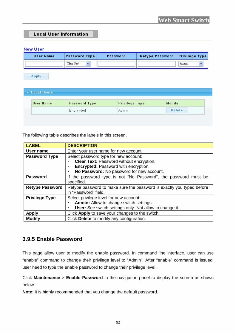
Web Smart Switch
92
The following table describes the labels in this screen.
LABEL DESCRIPTION User name Enter your user name for new account. Password Type Select password type for new account:
Clear Text: Password without encryption. Encrypted: Password with encryption. No Password: No password for new account.
Password If the password type is not “No Password”, the password must be specified.
Retype Password Retype password to make sure the password is exactly you typed before in “Password” field.
Privilege Type Select privilege level for new account: Admin: Allow to change switch settings. User: See switch settings only. Not allow to change it.
Apply Click Apply to save your changes to the switch. Modify Click Delete to modify any configuration.
3.9.5 Enable Password This page allow user to modify the enable password. In command line interface, user can use “enable” command to change their privilege level to “Admin”. After “enable” command is issued, user need to type the enable password to change their privilege level. Click Maintenance > Enable Password in the navigation panel to display the screen as shown below. Note: It is highly recommended that you change the default password.
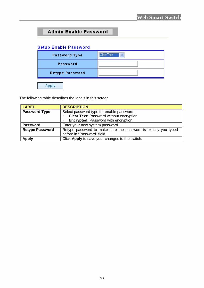
Web Smart Switch
93
The following table describes the labels in this screen.
LABEL DESCRIPTION Password Type Select password type for enable password:
Clear Text: Password without encryption. Encrypted: Password with encryption.
Password Enter your new system password. Retype Password Retype password to make sure the password is exactly you typed
before in “Password” field. Apply Click Apply to save your changes to the switch.
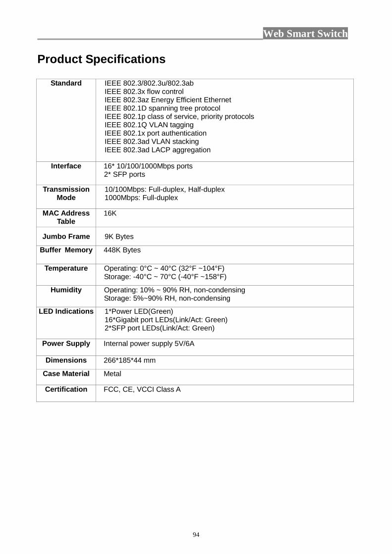
Web Smart Switch
94
Product Specifications
Standard IEEE 802.3/802.3u/802.3ab IEEE 802.3x flow control IEEE 802.3az Energy Efficient Ethernet IEEE 802.1D spanning tree protocol IEEE 802.1p class of service, priority protocols IEEE 802.1Q VLAN tagging IEEE 802.1x port authentication IEEE 802.3ad VLAN stacking IEEE 802.3ad LACP aggregation
Interface 16* 10/100/1000Mbps ports 2* SFP ports
Transmission Mode
10/100Mbps: Full-duplex, Half-duplex 1000Mbps: Full-duplex
MAC Address Table
16K
Jumbo Frame 9K Bytes
Buffer Memory 448K Bytes
Temperature Operating: 0°C ~ 40°C (32°F ~104°F) Storage: -40°C ~ 70°C (-40°F ~158°F)
Humidity Operating: 10% ~ 90% RH, non-condensing Storage: 5%~90% RH, non-condensing
LED Indications 1*Power LED(Green) 16*Gigabit port LEDs(Link/Act: Green) 2*SFP port LEDs(Link/Act: Green)
Power Supply Internal power supply 5V/6A
Dimensions 266*185*44 mm
Case Material Metal
Certification FCC, CE, VCCI Class A